Ham Radio 50MHz & aboveozaukeeradioclub.org/downloads/programs/2014_Dec_W9GA.pdf · Ham Radio 50MHz...
48
Ham Radio 50MHz & above • Evolution of this presentation: 1. New England Weak Signal (N.E.W.S.) Group • http://www.newsvhf.com/ 2. Northern Lights Radio Society (NLRS) • http://www.nlrs.org/ 3. Roadrunners Microwave Group (RMG) • http://www.k5rmg.org/ • Paul Goble ND2X • Thanks is given to all contributors!
Transcript of Ham Radio 50MHz & aboveozaukeeradioclub.org/downloads/programs/2014_Dec_W9GA.pdf · Ham Radio 50MHz...
Ham Radio 50MHz & above
• Evolution of this presentation:1. New England Weak Signal (N.E.W.S.) Group
• http://www.newsvhf.com/
2. Northern Lights Radio Society (NLRS)• http://www.nlrs.org/
3. Roadrunners Microwave Group (RMG)• http://www.k5rmg.org/
• Paul Goble ND2X
• Thanks is given to all contributors!

Amateur Bands above 50 MHz
(VHF/UHF/SHF….)
• VHF – 50 MHZ (6 m)
– 144 MHZ (2 m)
– 222 MHZ (135 cm)
• UHF – 432 MHZ (70 cm)
– 903 MHZ (33 cm)
– 1296 MHZ (23 cm)
– 2304 MHZ (13 cm)
• SHF – 3456 MHZ (9 cm)
– 5760 MHZ (6 cm)
– 10 GHZ (3 cm)
– 24 GHZ (12 mm)
• There ARE bands higher in
frequency; see:
http://www.k5rmg.org/bands.html
http://www.vhfsouth.org/tutorials/bands.htm
http://www.arrl.org/FandES/field/regulations/bandplan.html
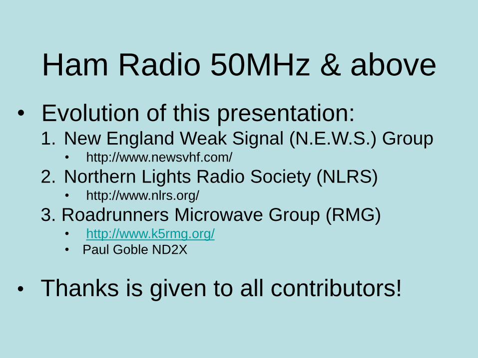
What can you expect?
Band Typical Range Enhanced Range
50 MHz 200 miles Worldwide
144 MHz 300 miles 500-1,300 miles
222 MHz 250 miles 500-1,300 miles
432 MHz 250 miles 400-1,000 miles
1296 MHz 150 miles 350-1,000 miles
2304 MHz 150 miles 250-1,000 miles
10 GHz 150 miles 250-1,000 miles
10-14dBd gain antenna, 150 W on 50/144/432MHz, 10 W on 1296 & 2304 MHz, 1 W on 10 GHz w/2 ft dish
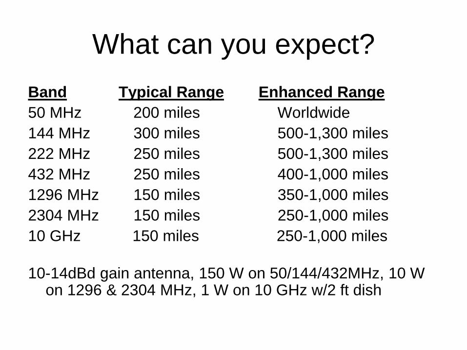
VHF Operators “collect” Gridsquares,
like an HF Operator collects countries
• Use of Worldwide “Maidenhead” grid system– Developed in Maidenhead, England in 1980
– Identifies location based on latitude / longitude
• World divided into 20° x 10° fields
• Each field divided into 100, 2° x 1° “squares” (or “grids”)
• Each “square” is divided into 576, 5’ x 2.5’ “subsquares” (“subgrids”)
• Examples:– West Bend is in grid EN53 (EN = field, 53 = “grid”)
– Port Washington is in grid EN63 (EN = field, 63 = “grid”
– W9GA’s Colgate home is in EN53ve (ve = “subgrid”)
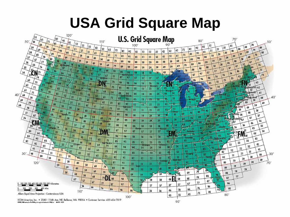
USA Grid Square Map

Maidenhead “Subgrids”
Grids: ~124.4 miles wide at Brownsville, TX, & ~90.9 miles wide at the Canadian border.
SUBgrids: ~5.2mi wide (Brownsville) to ~3.8 mi wide (Canada). There are 576 subgrids.

VUCC is like DXCC(VHF/UHF Century Club award)
Bands Grids req’d for VUCC
• 50 MHz, 144 MHz 100
• 222 MHz, 432 MHz 50
• 902 MHz, 1296 MHz 25
• 2304 MHz, 3456 MHz 10
• 5760 MHz, 10 GHz, 24 GHz 5

Propagation
• “Propagation” is how a signal gets from a
transmitter to a distant receiver.
• There are several types, or “modes”, of
propagation possible at VHF+ frequencies.
• The following slides list these modes with a few
of their characteristics. The goal here is simply
to understand there are many ways a VHF+
signal gets from a transmitter to a receiver.
Propagation Modes
• 1. Tropospheric Scatter
– Atmosphere scattering within troposphere
– Very reliable mode
– Workable on all bands with sufficient power
• 2. TROPO (ducting, bending, coastal)
– Weather-related enhancement
– Very common Apr-July in SE USA
– Workable on all bands with “normal” power
Propagation Modes
• 3. Aurora
– Common above 45 degrees latitude
– Not UNcommon above 40 degrees latitude
– Bounce signals off Auroral curtain
• All antennas pointed at the aurora
• Similar to HF backscatter or 10GHz rain scatter
– Common on 50 & 144 MHz
– Also works on 222 & 432 MHz when strong
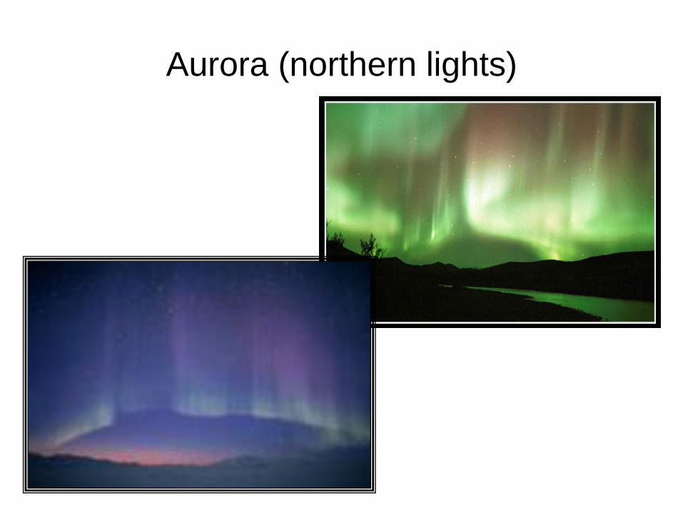
Aurora (northern lights)
Propagation Modes
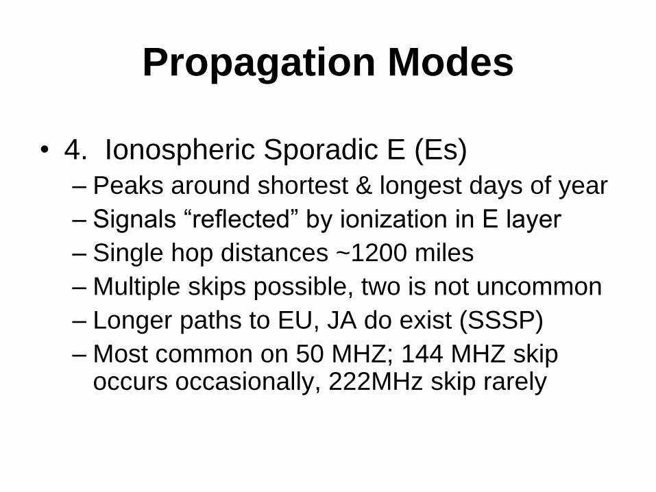
• 4. Ionospheric Sporadic E (Es)
– Peaks around shortest & longest days of year
– Signals “reflected” by ionization in E layer
– Single hop distances ~1200 miles
– Multiple skips possible, two is not uncommon
– Longer paths to EU, JA do exist (SSSP)
– Most common on 50 MHZ; 144 MHZ skip occurs occasionally, 222MHz skip rarely

Propagation Modes
• 5. Meteor scatter
– Reflecting signals off atmosphere ionized by
meteors burning up in the ionosphere
– Ionization occurs at E layer altitudes (~68mi)(higher if velocity is sufficiently fast; can get ~1300 mile “links”)
– Short duration communication opportunity
– Common & easy on 50 MHZ using “randoms”
– Works on 144 MHZ, esp. during “showers”
– Possible also on UHF during “showers”
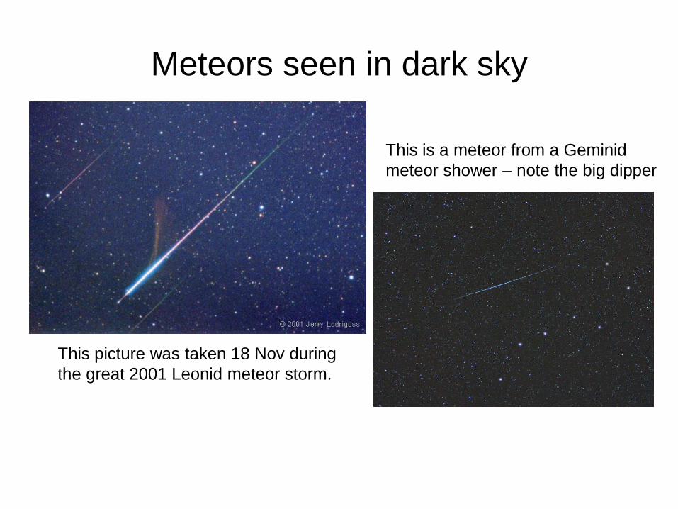
Meteors seen in dark sky
This picture was taken 18 Nov during
the great 2001 Leonid meteor storm.
This is a meteor from a Geminid
meteor shower – note the big dipper

Propagation Modes
• Other
– 6. Ionospheric scatter
– 7. Ionospheric F2 (like HF), ~155 mi altitude
– 8. TE (trans-equatorial, good to S. America)
– 9. Rain scatter (5, 10 GHz)
– 10. Airplane scatter (uWaves)
– 11. EME (“moonbounce”)
• Remember, the point is to realize there are
many ways VHF+ signals “travel”!

Getting on VHF/UHF/SHF bands
• Equipment is currently available for 50
MHz, 144 MHz, 432 MHz, 1296MHz– HF thru 432MHz (lacking 222MHz) common
• FT-100D, IC-706mkIIG, FT-857, FT897, etc.
– HF thru 1296MHz (lacking 222 & 902 MHz) available
• TS 2000X, Icom
– At least one example of 144, 432 and 1296 MHz
• IC-910H
– An older, hard-to-find radio offers a choice of four bands starting
with 50 MHz & going thru 144, 222, 432, & 1296 MHz
• FT-736R
– Old single-band gear exists, 28 – 1296MHz (no 902)
• IC-575, IC-275, IC-375, IC-475, IC1275

Getting on VHF/UHF/SHF bands
• Generally, currently available radios are
used as basis for 222, 902, & 2304MHz
thru 10 & 24 GHz
– Transverters used for frequency translation
– More complicated than radio alone
– Very capable
What’s a Transverter?
• Convert radio frequencies to bands not
otherwise available– IF (“Intermediate Frequency”) considerations; which band in an
existing radio to convert to/from the band of interest?
– Answer depends on how you operate & what gear you own
• Several sources for transverters & accessories– Downeast Microwave
– DB6NT (Kuhn)
– Elecraft
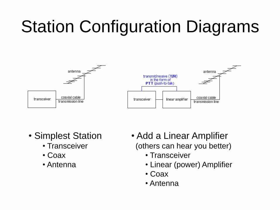
Station Configuration Diagrams
• Simplest Station• Transceiver
• Coax
• Antenna
• Add a Linear Amplifier(others can hear you better)
• Transceiver
• Linear (power) Amplifier
• Coax
• Antenna
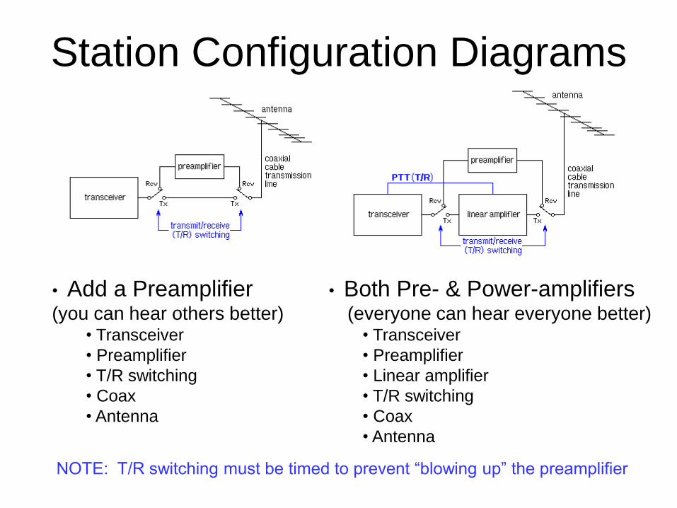
Station Configuration Diagrams
• Both Pre- & Power-amplifiers(everyone can hear everyone better)
• Transceiver
• Preamplifier
• Linear amplifier
• T/R switching
• Coax
• Antenna
• Add a Preamplifier(you can hear others better)
• Transceiver
• Preamplifier
• T/R switching
• Coax
• Antenna
NOTE: T/R switching must be timed to prevent “blowing up” the preamplifier
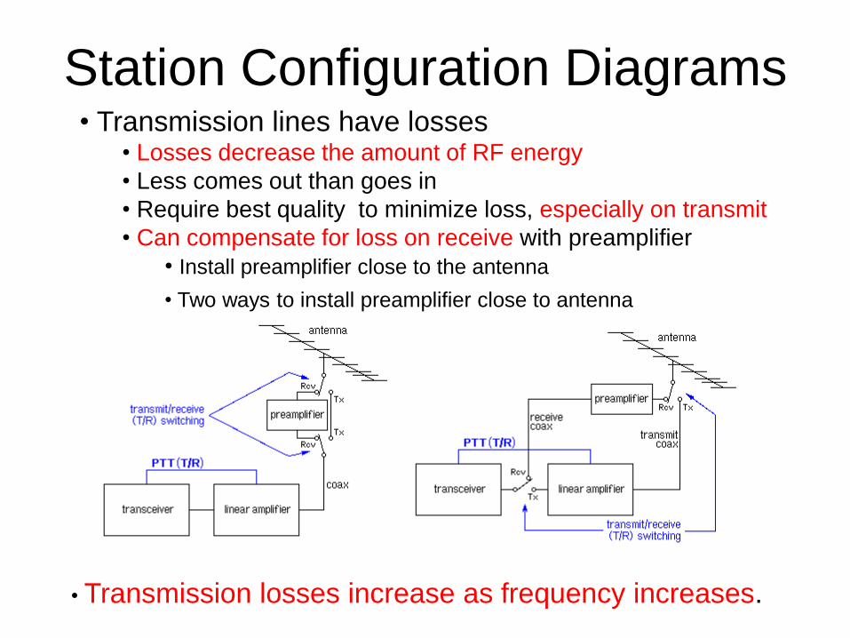
Station Configuration Diagrams• Transmission lines have losses
• Losses decrease the amount of RF energy
• Less comes out than goes in
• Require best quality to minimize loss, especially on transmit
• Can compensate for loss on receive with preamplifier
• Install preamplifier close to the antenna
• Two ways to install preamplifier close to antenna
• Transmission losses increase as frequency increases.
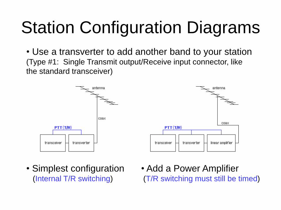
Station Configuration Diagrams
• Use a transverter to add another band to your station(Type #1: Single Transmit output/Receive input connector, like
the standard transceiver)
• Simplest configuration(Internal T/R switching)
• Add a Power Amplifier(T/R switching must still be timed)

Station Configuration Diagrams• Adding another band to your station using transverters
•Add a preamplifier •Both Pre- & Power-amplifiers
Generally, frequency of bands requiring use of transverters is high enough
to be concerned about the loss of the transmission line making “mast
mounted” the way to go!!
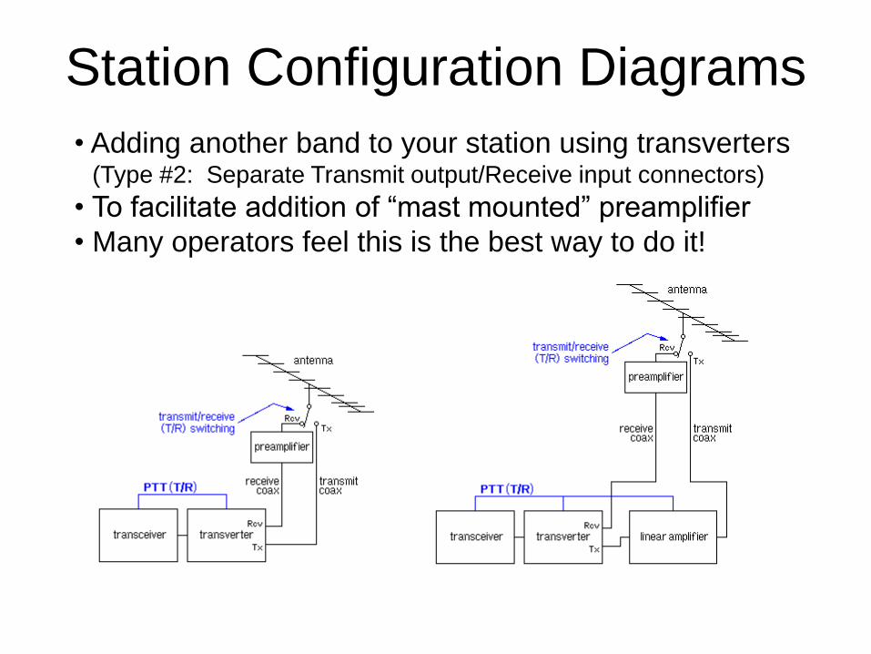
Station Configuration Diagrams
• Adding another band to your station using transverters(Type #2: Separate Transmit output/Receive input connectors)
• To facilitate addition of “mast mounted” preamplifier
• Many operators feel this is the best way to do it!

ANTENNASHorizontal polarization
– Less susceptible to man-made electrical noise
– Easier to install on vertical support mast
– Single yagis can experience ground-gain
• High-gain yagis have fairly narrow bandwidth
• Yagi gain proportional to boom length
• # of elements affect pattern, not gain, fixed boomlength

ANTENNAS• Can be home-built
Typical Yagi antenna sizes:
• Band Elements Boom Length
• 50 MHZ 4-7 12-36 feet
• 144 MHZ 8-18 10-36 feet
• 222 MHz 12-26 9-33 feet
• 432 MHZ 16-33 8-25 feet
• 1296 MHZ 23-55 4-15 feet
• 10 GHZ 2 foot dish N/A

VHF/UHF antenna stack (WZ1V)
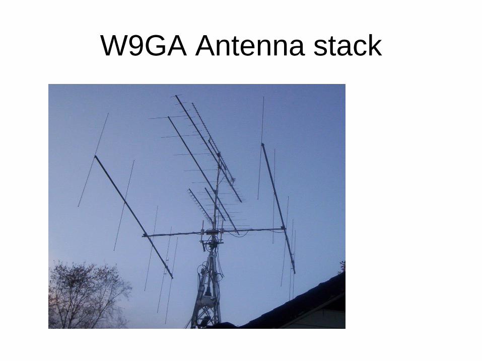
W9GA Antenna stack
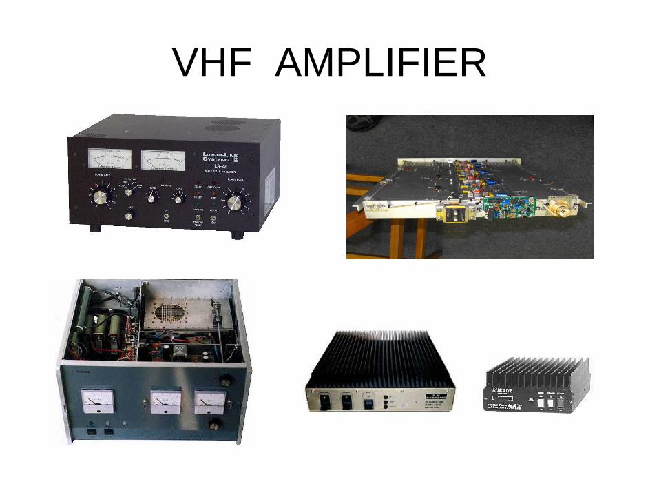
VHF AMPLIFIER
Amplifier sources
• Amplifier types:– Brick amplifiers: TE systems, Mirage/MFJ
– Hi Power SSHP; Larcan, Harris, W6PQL, Icom
– Tube amplifiers; Lunar Link, Henry, Heathkit (conv)
– Home Brew, usually tube amps
– Some Euro brands, both SSPA and Tubes (Russia)
– Some may have built in preamplifiers.

50 and 144 MHz KW SSHP
• With the advent of Digital TV in the USA and
abroad, several Kilowatt level solid state
amplifiers have hit the surplus market.
• Major types are Larcan and Harris ‘blade’ amps
• Run on 50 VDC, supplies easy to locate on Ebay
for low dollar cost
• Recycled amps cost about $300-$600 from
multiple sources.
Operating VHF+ DX• Location, Location, Location!
– Since most communication is “line of sight” or
troposcatter, location has significant impact!!
– Optimal: Antennas significantly above average
terrain (the reason “hilltopping” is popular with weak-
signal enthusiasts, especially “up east”!!)
– Desirable: Antenna above average terrain
– Most common: Antenna equal to average terrain
– Try to keep antennas above foliage or trees.
• RF absorption increases with frequency
• 6m, 2m and 222MHz not affected TOO much
• 432 MHz attenuated, 1296 and up nearly impossible

Front Range of the Colorado Rockies – not often
found in Wisc (interstate overpass, anyone?)!
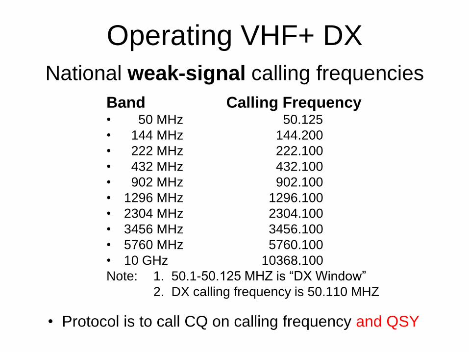
Operating VHF+ DX
Band Calling Frequency• 50 MHz 50.125
• 144 MHz 144.200
• 222 MHz 222.100
• 432 MHz 432.100
• 902 MHz 902.100
• 1296 MHz 1296.100
• 2304 MHz 2304.100
• 3456 MHz 3456.100
• 5760 MHz 5760.100
• 10 GHz 10368.100
Note: 1. 50.1-50.125 MHZ is “DX Window”
2. DX calling frequency is 50.110 MHZ
• Protocol is to call CQ on calling frequency and QSY
National weak-signal calling frequencies

Operating VHF+
• Typical QSO– Runs the range from DX (foreign)/contest type to ragchewing
– Common to exchange Grid Squares
– Unlike HF, “RST” not common (no such thing as “S zero”)
• Other– Antenna aiming challenge
– Ending transmission "W8CM (this is) ND2X (mobile 5) over"
– Wide open, (generally) QRM-free spectrum
– DO NOT ragchew on calling frequencies!
• You’re not “creating activity”
• You’re blanketing large areas with strong signals
• This PRECLUDES activity

Operating VHF+
• Contests and Band Openings
– Significant activity during both
– Generally more of an operating event than a
competition (for most ops)
– Competition is fun, too, if that’s your interest
• Major Contesting Events
– ARRL January Sweepstakes; June/Sept. QSO Parties
– ARRL August UHF, 10 GHZ and EME Contests
– CQ July VHF Contest
– Field Day, Fall & Spring Sprints

Operating VHF+
• Openings
– Increased activity
– Opportunity for extended range
• Indicators
– Checking the band; Using FM repeaters; Beacons; TV/FM Broadcast stations
– Weather reports; WWV; NOAA wx radio
– Packet/internet spots, APRS map “explosions”
– Time of the year (e.g., SW USA Apr-Jun)
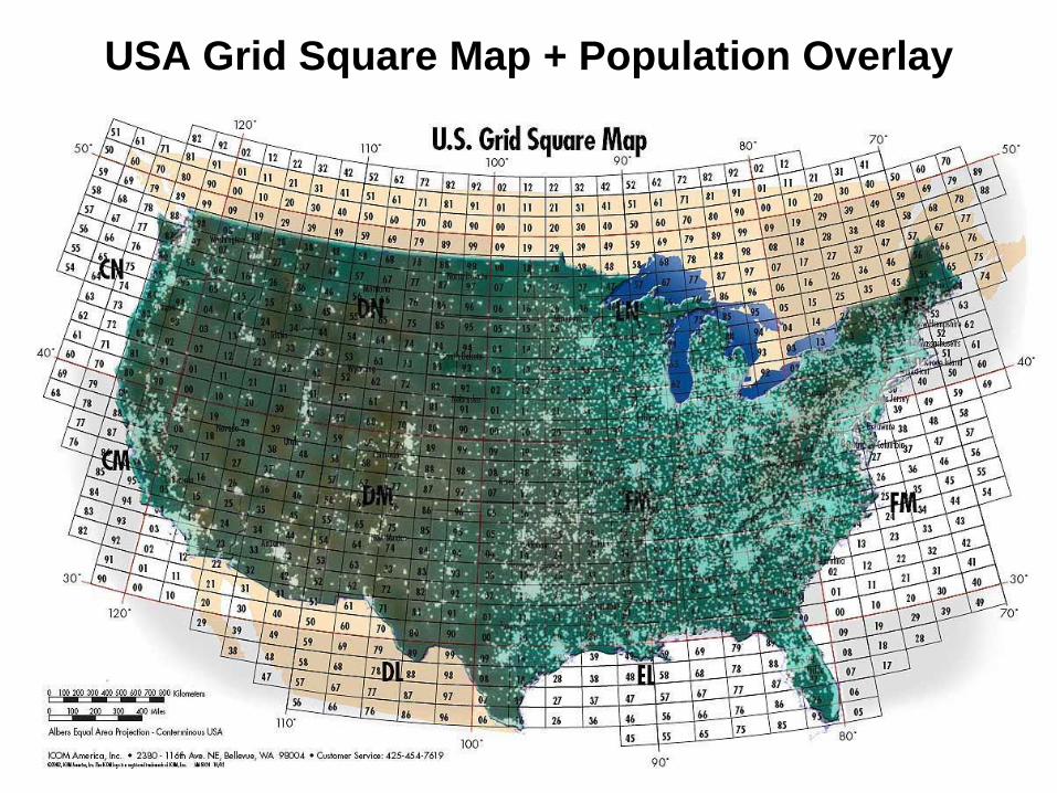
USA Grid Square Map + Population Overlay

Rovers (mobile stations)
• Mobile stations can be fancy or simple!!– The more bands and antennas, the fancier
– Antennas can be omni or directional
– Configuration depends on type of roving
• Mobile in motion (“Run ‘n’ Gun”)
• Portable from “hilltops” (“Shoot ‘n’ Scoot”)
• Simple rovers– magnetic mount antennas
– velcro & IC-706 Mk II G, FT-100D, FT-857, etc.
– Amplifiers if desired

Simple Rovers: 50, 144 & 432 MHz
Some mag-mount antennas, a little velcro & a tank of gas; a rover is born
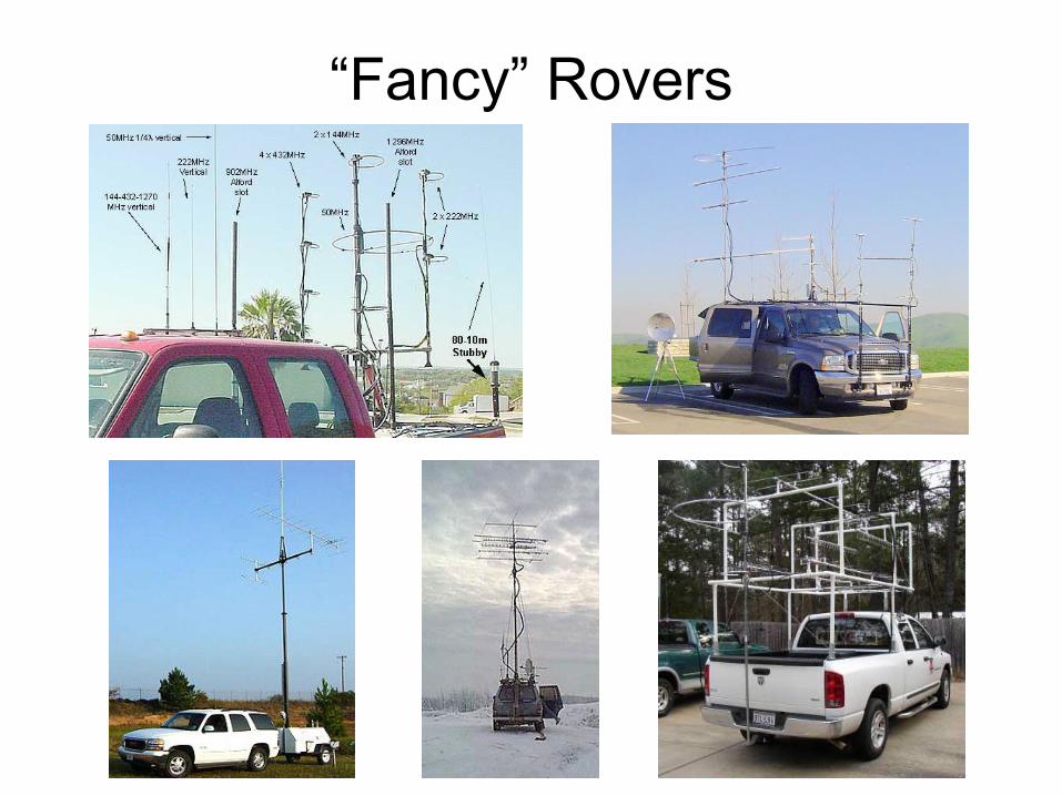
“Fancy” Rovers
Operating VHF+
• Challenging aspect of HAM Radio
– Many bands (16 allocations between 50MHz & 300 GHz)
– Many modes (analog, digital, weak signal, 802.11/x, …..)
– Many ways (fixed, mobile, portable, DX-peditions, .....)
– Many levels (simple, fancy, few bands, many bands, …..)
– Digital EME, HSMS, etc.; using WSJT,JT65
• Lots of room for more activity
• ANYbody can bounce signals off the ionosphere!
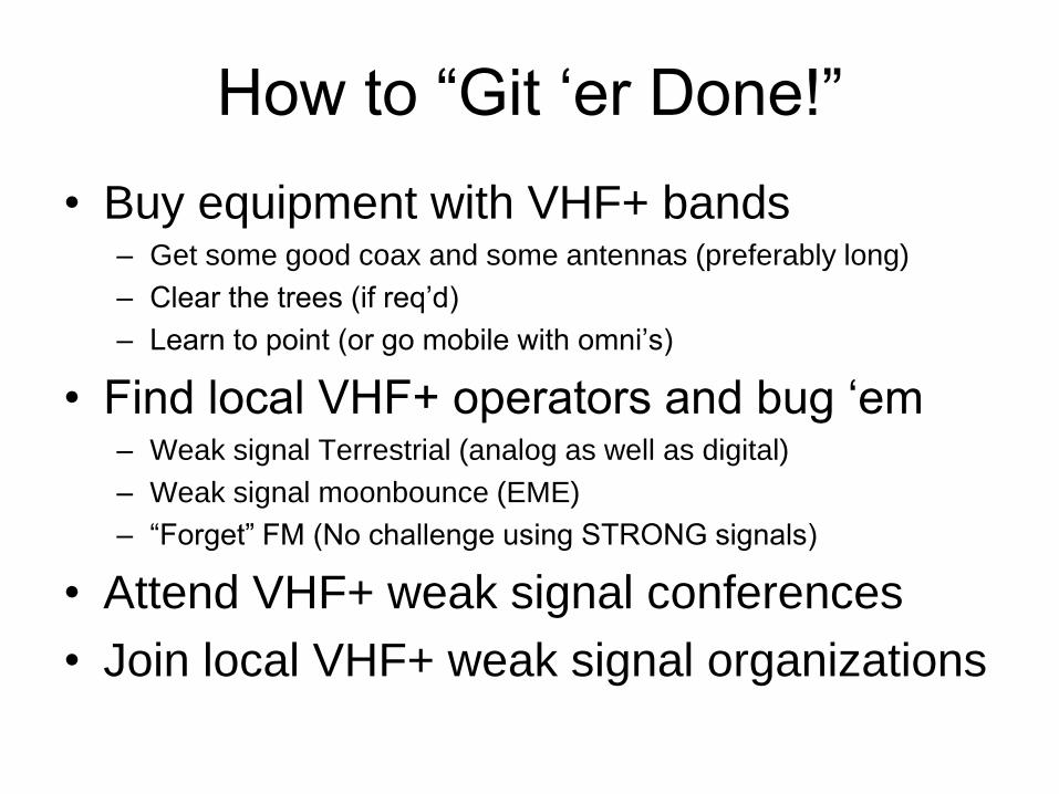
How to “Git ‘er Done!”
• Buy equipment with VHF+ bands– Get some good coax and some antennas (preferably long)
– Clear the trees (if req’d)
– Learn to point (or go mobile with omni’s)
• Find local VHF+ operators and bug ‘em– Weak signal Terrestrial (analog as well as digital)
– Weak signal moonbounce (EME)
– “Forget” FM (No challenge using STRONG signals)
• Attend VHF+ weak signal conferences
• Join local VHF+ weak signal organizations
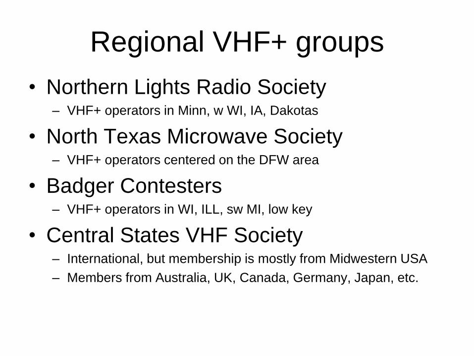
Regional VHF+ groups
• Northern Lights Radio Society– VHF+ operators in Minn, w WI, IA, Dakotas
• North Texas Microwave Society– VHF+ operators centered on the DFW area
• Badger Contesters – VHF+ operators in WI, ILL, sw MI, low key
• Central States VHF Society– International, but membership is mostly from Midwestern USA
– Members from Australia, UK, Canada, Germany, Japan, etc.
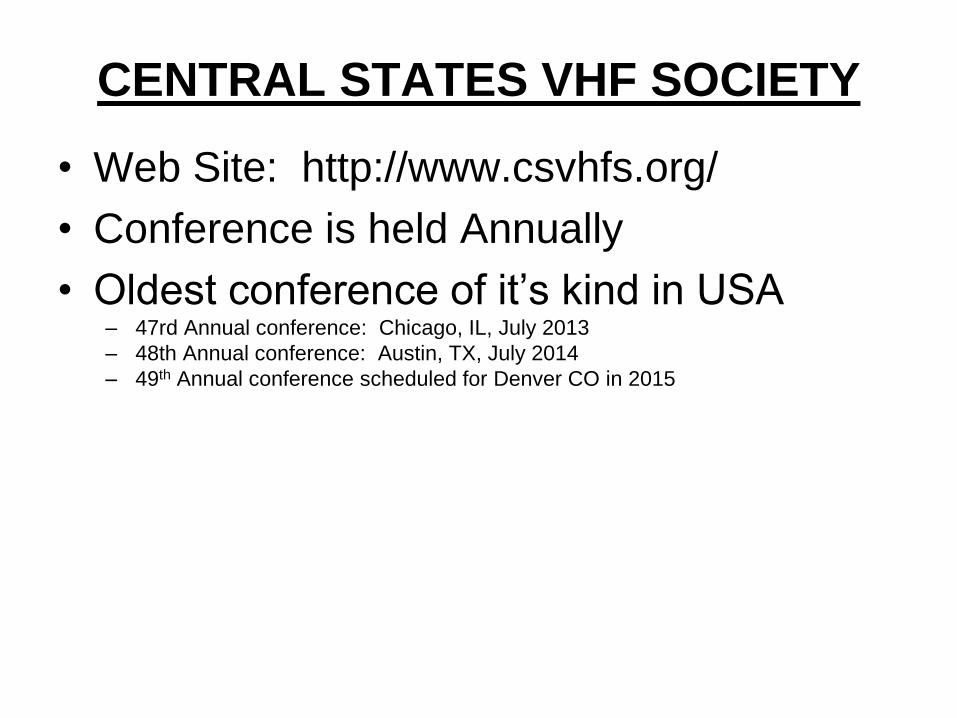
CENTRAL STATES VHF SOCIETY
• Web Site: http://www.csvhfs.org/
• Conference is held Annually
• Oldest conference of it’s kind in USA– 47rd Annual conference: Chicago, IL, July 2013
– 48th Annual conference: Austin, TX, July 2014
– 49th Annual conference scheduled for Denver CO in 2015
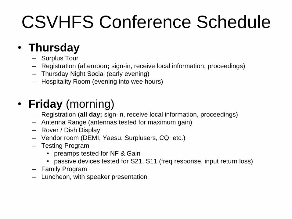
CSVHFS Conference Schedule
• Thursday– Surplus Tour
– Registration (afternoon; sign-in, receive local information, proceedings)
– Thursday Night Social (early evening)
– Hospitality Room (evening into wee hours)
• Friday (morning)– Registration (all day; sign-in, receive local information, proceedings)
– Antenna Range (antennas tested for maximum gain)
– Rover / Dish Display
– Vendor room (DEMI, Yaesu, Surplusers, CQ, etc.)
– Testing Program
• preamps tested for NF & Gain
• passive devices tested for S21, S11 (freq response, input return loss)
– Family Program
– Luncheon, with speaker presentation
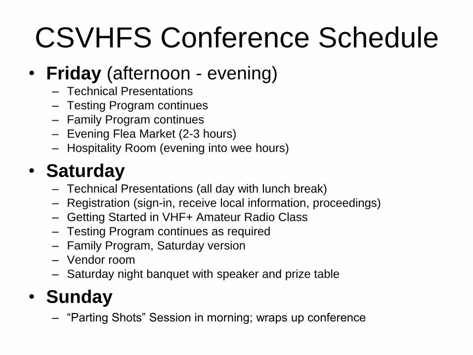
CSVHFS Conference Schedule• Friday (afternoon - evening)
– Technical Presentations
– Testing Program continues
– Family Program continues
– Evening Flea Market (2-3 hours)
– Hospitality Room (evening into wee hours)
• Saturday– Technical Presentations (all day with lunch break)
– Registration (sign-in, receive local information, proceedings)
– Getting Started in VHF+ Amateur Radio Class
– Testing Program continues as required
– Family Program, Saturday version
– Vendor room
– Saturday night banquet with speaker and prize table
• Sunday– “Parting Shots” Session in morning; wraps up conference
Ham Radio Above 50MHz
• Thanks for listening
• Do you have any Questions?


![Ham [Read-Only] Ham Beetles, Cheese Skippers, Ham Mites](https://static.fdocuments.net/doc/165x107/5abdea347f8b9a7e418c3fd3/ham-read-only-ham-beetles-cheese-skippers-ham-mites.jpg)