HALFEN HSC STUD CONNECTOR - downloads.halfen.com · magnet is located in the middle of the...
16
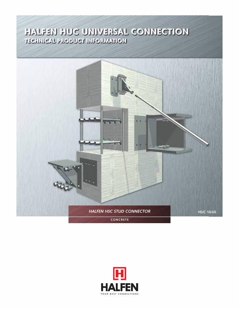
HUC 10-US HALFEN HSC STUD CONNECTOR CONCRETE
Transcript of HALFEN HSC STUD CONNECTOR - downloads.halfen.com · magnet is located in the middle of the...
HUC 10-USHALFEN HSC STUD CONNECTOR
CONCRETE
2
HALFEN HUC UNIVERSAL CONNECTION
© 2012 HALFEN · HUC 10-US · www.halfenusa.com
FEd FEdFEd
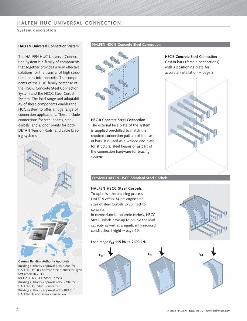
HALFEN Universal Connection System
The HALFEN HUC Universal Connec-tion System is a family of components that together provides a very effective solutions for the transfer of high struc-tural loads into concrete. The compo-nents of the HUC family comprise of the HSC-B Concrete Steel Connection System and the HSCC Steel Corbel System. The load range and adaptabil-ity of these components enables the HUC system to offer a huge range of connection applications. These include connections for steel beams, steel corbels, and anchor points for both DETAN Tension Rods, and cable brac-ing systems.
HSC-B Concrete Steel ConnectionCast-in bars (female connections) with a positioning plate for accurate installation → page 3.
HSC-B Concrete Steel Connection The external face plate of the system is supplied pre-drilled to match the required connection pattern of the cast-in bars. It is used as a welded end plate for structural steel beams or as part of the connection hardware for bracing systems.
HALFEN HSCC Steel CorbelsTo optimise the planning process HALFEN offers 34 pre-engineered sizes of steel Corbels to connect to concrete. In comparison to concrete corbels, HSCC Steel Corbels have up to double the load capacity as well as a significantly reduced construction height → page 15.
Building authority approval Z-15.6-284 for HALFEN HSC-B Concrete Steel Connector Type test report in 2011 for HALFEN HSCC Steel CorbelsBuilding authority approval Z-15.6-204 for HALFEN HSC Stud ConnectorBuilding authority approval Z-1.5-189 for HALFEN HBS-05 Screw Connection
German Building Authority Approvals
HALFEN HSC-B Concrete Steel Connection
Preview HALFEN HSCC Standard Steel Corbels
Load range FEd 115 kN to 2600 kN.
System description
3
HALFEN HUC UNIVERSAL CONNECTION
© 2012 HALFEN · HUC 10-US · www.halfenusa.com
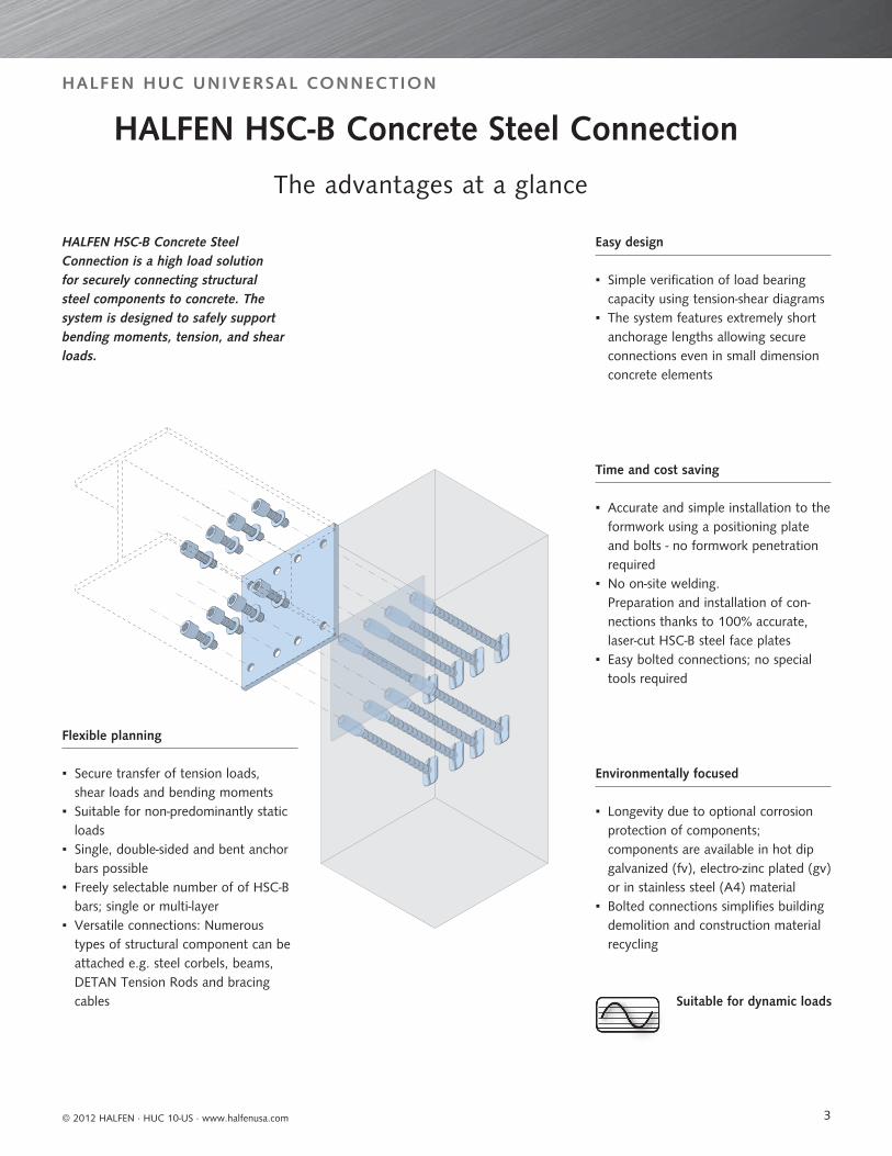
HALFEN HSC-B Concrete Steel Connection is a high load solution for securely connecting structural steel components to concrete. The system is designed to safely support bending moments, tension, and shear loads.
Flexible planning
▪ Secure transfer of tension loads,shear loads and bending moments
▪ Suitable for non-predominantly static loads
▪ Single, double-sided and bent anchor bars possible
▪ Freely selectable number of of HSC-B bars ; single or multi-layer ▪ Versatile connections: Numerous
types of structural component can be attached e.g. steel corbels, beams, DETAN Tension Rods and bracing cables
Easy design
▪ Simple verification of load bearing capacity using tension-shear diagrams ▪ The system features extremely short anchorage lengths allowing secure connections even in small dimension concrete elements
Environmentally focused
▪ Longevity due to optional corrosion protection of components; components are available in hot dip galvanized (fv), electro-zinc plated (gv) or in stainless steel (A4) material
▪ Bolted connections simplifies building demolition and construction material recycling
Time and cost saving
▪ Accurate and simple installation to the formwork using a positioning plate and bolts - no formwork penetration required
▪ No on-site welding.Preparation and installation of con-nections thanks to 100% accurate, laser-cut HSC-B steel face plates
▪ Easy bolted connections; no special tools required
Suitable for dynamic loads
HALFEN HSC-B Concrete Steel Connection
The advantages at a glance
4
HALFEN HUC UNIVERSAL CONNECTION
© 2012 HALFEN · HUC 10-US · www.halfenusa.com
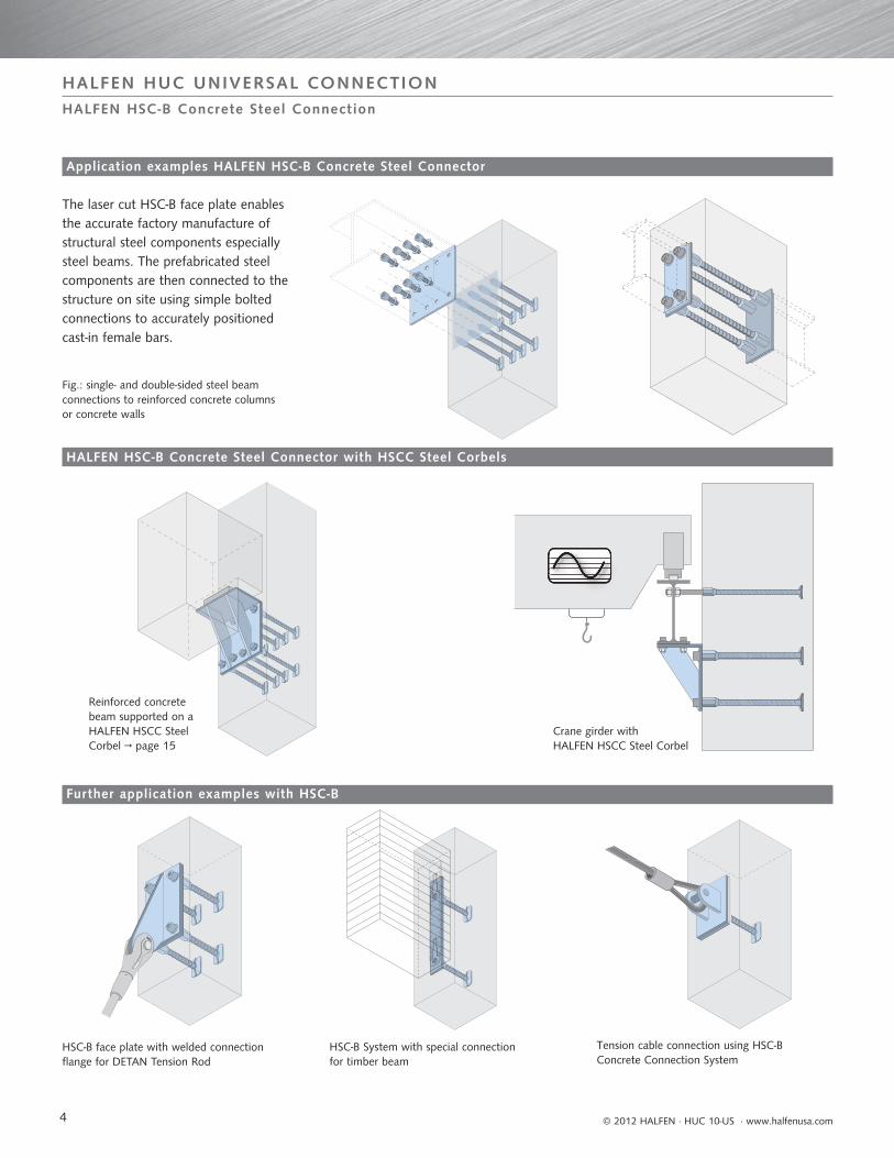
Reinforced concrete beam supported on a HALFEN HSCC Steel Corbel → page 15
HSC-B face plate with welded connection flange for DETAN Tension Rod
HSC-B System with special connection for timber beam
Tension cable connection using HSC-BConcrete Connection System
Fig.: single- and double-sided steel beam connections to reinforced concrete columns or concrete walls
Crane girder with HALFEN HSCC Steel Corbel
The laser cut HSC-B face plate enablesthe accurate factory manufacture ofstructural steel components especiallysteel beams. The prefabricated steelcomponents are then connected to thestructure on site using simple boltedconnections to accurately positioned cast-in female bars.
HALFEN HSC-B Concrete Steel Connector with HSCC Steel Corbels
Application examples HALFEN HSC-B Concrete Steel Connector
Further application examples with HSC-B
HALFEN HSC-B Concrete Steel Connection

5
HALFEN HUC UNIVERSAL CONNECTION
© 2012 HALFEN · HUC 10-US · www.halfenusa.com
HALFEN HSC-B Concrete Steel Connec-tor using HSC-B SH female bars in 2 groups of 4 to form a connection for a steel beam to a reinforced concrete column.
1. Remove the thread protector immediately prior to installation
4. The positioning plate with its atta-ched female bars is attached either with a magnet to a steel formwork, or by nailing to timber formwork.
5. The column and additional reinforce-ment is positioned according to the requirement of the structural engineer
→ see also page 13
7. After the concrete has been poured and the formwork removed the thread-protecter is replaced until final installation of components to prevent corrosion.
8. Structural steel beam with HSC-B face plate is bolted into position.
2. Connection of the HSC-B SH female bars to the positioning plate using flat headed bolts.
3. Cutting and fitting of adhesive foam sheet to form a recess in the concrete at the connection location. When used with steel formwork a magnet is located in the middle of the positioning plate. Accessories → page 7
6. The female bars should be securely tied to the column reinforcement
Alternatively: The positioning plate can be mounted flush if drilling the formwork is preferred
Formwork
Positioning plate
Installation example
HALFEN HSC-B Concrete Steel Connection

6
5 mm
5 mm
hc
bc
tc
hp
bp
tp = 3mm
u
L
ds
L
ds
HALFEN HUC UNIVERSAL CONNECTION
© 2012 HALFEN · HUC 10-US · www.halfenusa.com
Different edge distances for thebolt holes in the positioning and in the face plate.
To order please provide a drawing withthe following information.
Positioning plate: Dimensions bp and hp, plus position and diameters of bolt, and nailing holes. Type of corrosion-protection.Face plate: Dimensions bc, hc, tc, plus position and diameters of the bolt holes. Required material.
HSC-B SH with forged head. Especially suitable for short anchoring lengths.
HSC-B SD especially suited for double-sidedconnections of componemts to columns and walls.
Recommendation: For easy installation use a positioning plate with a slightly larger footprint than the face plate.i.e. bp = bc + 10 mm, hp = hc + 10 mm(to give 5 mm clearance all around)
HSC-B P Positioning Plate
Face plate
Product overview
HSC-B FP Face Plate
HALFEN HSC-B Concrete Steel Connection
HSC-B Positioning- and face plates P /FP
Type Finish Article no.
Positioning plates
HSC-B P Hot dip galvanized [fv]/ Electro-zinc plated [gv] 1060.409-00001
Face plates
HSC-B FP Mill finish 1060.409-00002
HSC-B SH female bar with anchor head
Type ds L
Article no.Hot dip galvanized [fv]
Article no.Stainless steel [A4]
Article no.Electro-zinc plated [gv]
HSC-B SH- 16 ... 1060.010 1060.020 1060.030
HSC-B SH- 20 ... 1060.040 1060.050 1060.060
HSC-B SH- 25 ... 1060.070 1060.080 1060.090
Finish applies to exposed female threaded connection sleeve. Bars are mill finish carbon steel
HSC-B SD double sided female bar
Type ds L
Article no.Hot dip galvanized [fv]
Article no.Stainless steel [A4]
Article no.Electro-zinc plated [gv]
HSC-B SD- 16 ... 1060.210 1060.220 1060.230
HSC-B SD- 20 ... 1060.240 1060.250 1060.260
HSC-B SD- 25 ... 1060.270 1060.280 1060.290
Finish applies to exposed female threaded connection sleeve. Bars are mill finish carbon steel

7
L
ds
x
y
dBr
ds
L L
HALFEN HUC UNIVERSAL CONNECTION
© 2012 HALFEN · HUC 10-US · www.halfenusa.com
HSC-B S especially suited for connections to slabs with sufficient anchor depth.
HSC-B SB especially suited for load transfer in columns or walls of adequate dimension.
≥ 3 mm foam sheet (shuttering aid)
3 mm positioning plate
Face plate
Application with sliding formwork: Positioning plate is installed recessed with flat headed bolts.
Face plate
3 mm positioning plate
Application with drilled formwork:Positioning plate is flush to formwork.
Accessories
Product overview
Installation Variations
HALFEN HSC-B Concrete Steel Connection
HSC-B SE Sealing accessories for concreting
Article name Article no. Description
HSC-B SE 1060.420-00001 Foam sheet one-sided self adhesive 15 x 15 mm, length 1000 mm
HSC-B FI Flat-headed assembly bolt for positioning plate – 3 mm head
Article-name type nominal size Article no. Nominal size Length L
HSC-B FI M 16 1060.410-00001 M 16 25
HSC-B FI M 20 1060.410-00002 M 20 25
HSC-B FI M 27 1060.410-00003 M 27 30
HSC-B SB bent female bar
Type ds L/x/y/dBr/
Article no.Hot dip galvanized [fv]
Article no.Stainless steel A4
Article no.Electro-zinc plated [gv]
HSC-B SB-16 .../.../.../... 1060.110 1060.120 1060.130
HSC-B SB-20 .../.../.../... 1060.140 1060.150 1060.160
HSC-B SB-25 .../.../.../... 1060.170 1060.180 1060.190
Dimensions and bend radius information required. Recommended dBr ≥ 10 ds
Standard bending angle = 90°, if not differently stated.
Corrosion protection for sockets. Bars are mill finish carbon steel.
HSC-B S female bar
Type ds L
Article no.Hot dip galvanized [fv]
Article no.Stainless steel [A4]
Article no.Electro-zinc plated [gv]
HSC-B S- 16 ... 1060.310 1060.320 1060.330
HSC-B S- 20 ... 1060.340 1060.350 1060.360
HSC-B S- 25 ... 1060.370 1060.380 1060.390
Corrosion protection for sockets. Bars are mill finish carbon steel.
8
min 1 ds
L1
dL
u
aij
aij
aij
aij,edge
aij,edge
HALFEN HUC UNIVERSAL CONNECTION
© 2012 HALFEN · HUC 10-US · www.halfenusa.com
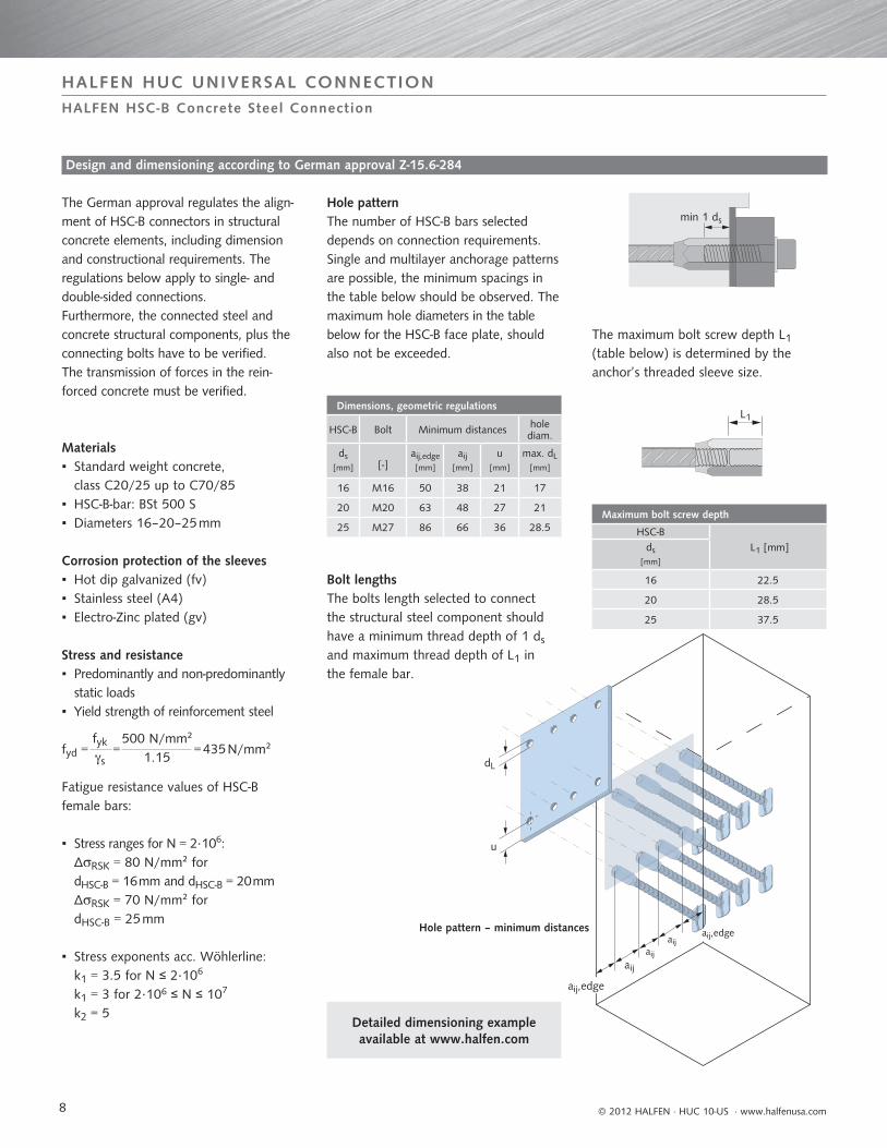
The German approval regulates the align-ment of HSC-B connectors in structural concrete elements, including dimension and constructional requirements. The regulations below apply to single- and double-sided connections.Furthermore, the connected steel and concrete structural components, plus the connecting bolts have to be verified.The transmission of forces in the rein-forced concrete must be verified.
Materials ▪ Standard weight concrete,
class C20/25 up to C70/85 ▪ HSC-B-bar: BSt 500 S ▪ Diameters 16–20–25 mm
Corrosion protection of the sleeves ▪ Hot dip galvanized (fv) ▪ Stainless steel (A4) ▪ Electro-Zinc plated (gv)
Stress and resistance ▪ Predominantly and non-predominantly
static loads ▪ Yield strength of reinforcement steel
fyd = fyk s
= 500 N/mm²
1.15 = 435 N/mm²
Fatigue resistance values of HSC-B female bars:
▪ Stress ranges for N = 2·106: ΔRSK = 80 N/mm² for dHSC-B = 16 mm and dHSC-B = 20 mm ΔRSK = 70 N/mm² for dHSC-B = 25 mm
▪ Stress exponents acc. Wöhlerline: k1 = 3.5 for N ≤ 2·106
k1 = 3 for 2·106 ≤ N ≤ 107
k2 = 5
Hole patternThe number of HSC-B bars selected depends on connection requirements. Single and multilayer anchorage patterns are possible, the minimum spacings in the table below should be observed. The maximum hole diameters in the table below for the HSC-B face plate, should also not be exceeded.
Bolt lengthsThe bolts length selected to connect the structural steel component should have a minimum thread depth of 1 ds and maximum thread depth of L1 in the female bar.
The maximum bolt screw depth L1 (table below) is determined by the anchor’s threaded sleeve size.
Hole pattern – minimum distances
Detailed dimensioning example available at www.halfen.com
Design and dimensioning according to German approval Z-15.6-284
HALFEN HSC-B Concrete Steel Connection
Dimensions, geometric regulations
HSC-B Bolt Minimum distances hole diam.
ds[mm] [-]
aij,edge[mm]
aij[mm]
u[mm]
max. dL[mm]
16 M16 50 38 21 17
20 M20 63 48 27 21
25 M27 86 66 36 28.5Maximum bolt screw depth
HSC-B L1 [mm]ds
[mm]
16 22.5
20 28.5
25 37.5
9
HALFEN HUC UNIVERSAL CONNECTION
© 2012 HALFEN · HUC 10-US · www.halfenusa.com
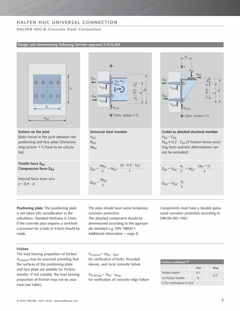
Positioning plate: The positioning plate is not taken into consideration in the calculation. Standard thickness is 3 mm. If the concrete pour requires a vent-hole a provision for a hole (≥ 4 mm) should be made.
The plate should have some temporary corrosion protection.The attached component should bedimensioned according to the appropri-ate standard e.g. DIN 18800-1.Additional information → page 8.
Components must have a durable galva-nized corrosion protection according to DIN EN ISO 1461.
FrictionThe load bearing proportion of frictionVfr,Ed,inf may be assumed providing that the surfaces of the positioning plate and face plate are suitable for friction transfer. If not suitable, the load bearing proportion of friction may not be assu-med (see table).
Vfr,Ed,inf = DEd · μinf
for verification of bolts, threaded sleeves, and local concrete failure
Vfr,Ed,sup = DEd · μsup for verification of concrete edge failure
Geometry
Design and dimensioning following German approval Z-15.6-284
HALFEN HSC-B Concrete Steel Connection
Actions on the jointStatic forces in the joint between the positioning and face plate (Dimensio-ning section 1-1) have to be calcula-ted.
Universal steel memberVEd
NEd
MEd
Corbel as attached structural memberVEd = FEd
HEd ≥ 0,2 · FEd (if friction forces resul-ting from restraint deformations can not be excluded)
Tensile force ZEd,Compressive force DEd
Internal force lever armz = 0.9 · d
ZEd = MEd
z + NEd ·
(d - 0.5 · hc)
z
DEd = z
MEd
ZEd = VEd · ac
z + HEd ·
(aH + z)z
DEd = VEd · zac
bc
hc
bcol
ZEd
DEd
Vij,Ed
Vij,Ed
Vfr,Ed
VEd, NEd,MEd
dh c
1 1
ZEd
FEdHEd
Vij,Ed
Vij,EdVfr,Ed
a H
dh c
ac
DEd
1 (Dim. section 1-1) 1 (Dim. section 1-1)
z =
0.9
· d
z =
0.9
· d
Friction coefficients
μinf μsup
friction tranfer 0.10.2
no friction transfer 0
For verifications in ULS
10
HALFEN HUC UNIVERSAL CONNECTION
© 2012 HALFEN · HUC 10-US · www.halfenusa.com
Design values permissable accord-ing to the German approval for the HSC-B anchors threaded sleeves
Static actions: Nij,Ed = ZEd
ntie Vij,Ed =
(VEd – Vfr,Ed,inf)ntot
Dimensioning of the bolts (N-V interaction acc. to DIN 18800-1)
Resistances: Nij,Rd = min ASp ·
fy,b,k
1.1 · M
ASp · fu,b,k
1.25 · M
Vij,Rd = ASp · a · fu,b,k
M
Interaction verification: Nij,Ed Nij,Rd
2
+ Vij,Ed Vij,Rd
2
≤ 1.0
According to DIN 18800 interaction verification may be omitted, if Nij,Ed/Nij,Rd ≤ 0.25 or Vij,Ed/Vij,Rd ≤ 0.25
Recommendation: determine the number of bolts in the pre-selection graphs as shown on pages 11 and 12.
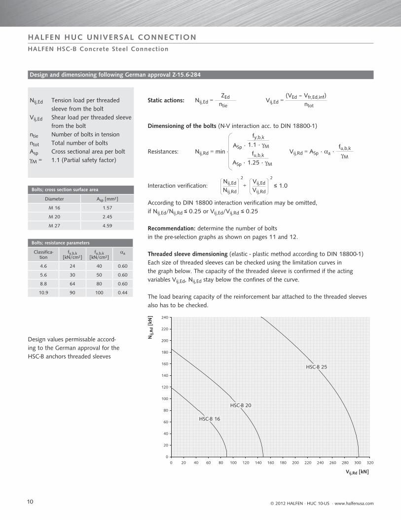
Threaded sleeve dimensioning (elastic - plastic method according to DIN 18800-1)Each size of threaded sleeves can be checked using the limitation curves in the graph below. The capacity of the threaded sleeve is confirmed if the acting variables Vij,Ed, Nij,Ed stay below the confines of the curve.
The load bearing capacity of the reinforcement bar attached to the threaded sleeves also has to be checked.
Design and dimensioning following German approval Z-15.6-284
HALFEN HSC-B Concrete Steel Connection
Nij,Ed Tension load per threaded sleeve from the bolt
Vij,Ed Shear load per threaded sleeve from the bolt
ntie Number of bolts in tensionntot Total number of boltsAsp Cross sectional area per boltM = 1.1 (Partial safety factor)
Bolts; cross section surface area
Diameter Asp [mm²]
M 16 1.57
M 20 2.45
M 27 4.59
Bolts; resistance parameters
Classifica-tion
fy,b,k [kN/cm²]
fu,b,k[kN/cm²]
a
4.6 24 40 0.60
5.6 30 50 0.60
8.8 64 80 0.60
10.9 90 100 0.44
Nij,
Rd [
kN]
Vij,Rd [kN]
0
20
40
60
80
100
120
140
160
180
200
220
240
0 20 40 60 80 100 120 140 160 180 200 220 240 260 280 300 320
HSC-B 25
HSC-B 20
HSC-B 16
11
HALFEN HUC UNIVERSAL CONNECTION
© 2012 HALFEN · HUC 10-US · www.halfenusa.com
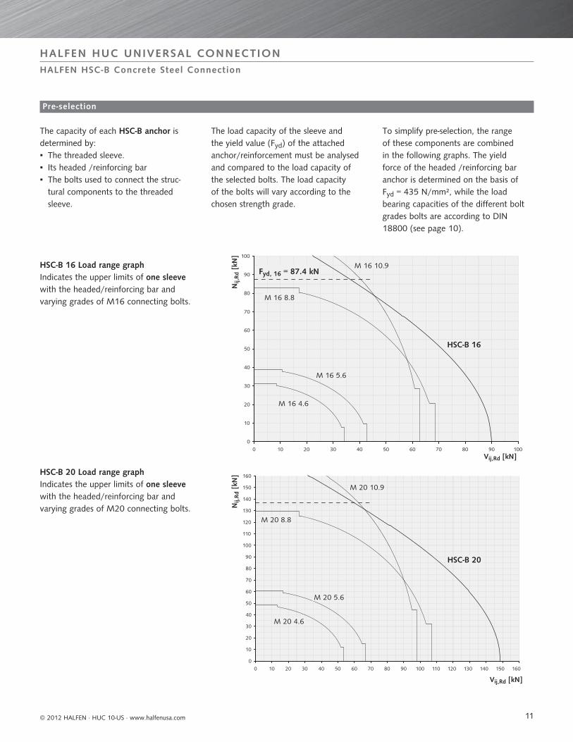
HSC-B 16 Load range graph Indicates the upper limits of one sleeve with the headed/reinforcing bar and varying grades of M16 connecting bolts.
The load capacity of the sleeve and the yield value (Fyd) of the attached anchor/reinforcement must be analysed and compared to the load capacity of the selected bolts. The load capacity of the bolts will vary according to the chosen strength grade.
The capacity of each HSC-B anchor is determined by: ▪ The threaded sleeve. ▪ Its headed /reinforcing bar ▪ The bolts used to connect the struc-tural components to the threaded sleeve.
To simplify pre-selection, the range of these components are combined in the following graphs. The yield force of the headed /reinforcing bar anchor is determined on the basis of Fyd = 435 N/mm², while the load bearing capacities of the different bolt grades bolts are according to DIN 18800 (see page 10).
HSC-B 20 Load range graph Indicates the upper limits of one sleeve with the headed/reinforcing bar and varying grades of M20 connecting bolts.
Pre-selection
HALFEN HSC-B Concrete Steel Connection
Nij,
Rd [
kN]
Vij,Rd [kN]
0
10
20
30
40
50
60
70
80
90
100
0 10 20 30 40 50 60 70 80 90 100
HSC-B 16
M 16 4.6
M 16 5.6
M 16 8.8
M 16 10.9Fyd, 16 = 87.4 kN
Fyd, 20 = 136.6 kN
Vij,Rd [kN]
0
10
20
30
40
50
60
70
80
90
100
110
120
130
140
150
160
0 10 20 30 40 50 60 70 80 90 100 110 120 130 140 150 160
M 20 4.6
M 20 5.6
M 20 8.8
M 20 10.9
HSC-B 20
Nij,
Rd [
kN]
12
HALFEN HUC UNIVERSAL CONNECTION
© 2012 HALFEN · HUC 10-US · www.halfenusa.com
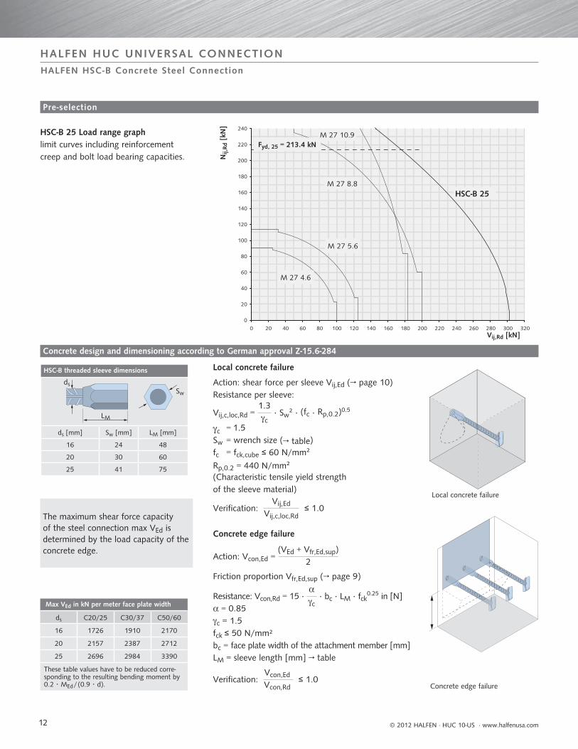
HSC-B 25 Load range graphlimit curves including reinforcement creep and bolt load bearing capacities.
Local concrete failure
Concrete edge failure
Local concrete failure
Action: shear force per sleeve Vij,Ed (→ page 10)Resistance per sleeve:
Vij,c,loc,Rd = 1.3c
· Sw² · (fc · Rp,0.2)0.5
c = 1.5Sw = wrench size (→ table)fc = fck,cube ≤ 60 N/mm²
Rp,0.2 = 440 N/mm² (Characteristic tensile yield strength of the sleeve material)
Verification: Vij,Ed
Vij,c,loc,Rd ≤ 1.0
Concrete edge failure
Action: Vcon,Ed = (VEd + Vfr,Ed,sup)
2
Friction proportion Vfr,Ed,sup (→ page 9)
Resistance: Vcon,Rd = 15 · c
· bc · LM · fck0.25 in [N] = 0.85c = 1.5fck ≤ 50 N/mm²bc = face plate width of the attachment member [mm]LM = sleeve length [mm] → table
Verification: Vcon,Ed
Vcon,Rd ≤ 1.0
Pre-selection
Concrete design and dimensioning according to German approval Z-15.6-284
HALFEN HSC-B Concrete Steel Connection
HSC-B threaded sleeve dimensions
ds [mm] Sw [mm] LM [mm]
16 24 48
20 30 60
25 41 75
Nij,
Rd [
kN]
Vij,Rd [kN]
0
20
40
60
80
100
120
140
160
180
200
220
240
0 20 40 60 80 100 120 140 160 180 200 220 240 260 280 300 320
M 27 10.9
M 27 8.8
M 27 5.6
M 27 4.6
HSC-B 25
Fyd, 25 = 213.4 kN
The maximum shear force capacity of the steel connection max VEd is determined by the load capacity of the concrete edge.
Max VEd in kN per meter face plate width
ds C20/25 C30/37 C50/60
16 1726 1910 2170
20 2157 2387 2712
25 2696 2984 3390
These table values have to be reduced corre-sponding to the resulting bending moment by0.2 · MEd / (0.9 · d).
LM
Sw
ds
13
Minimum diameter for stirrups and longitudinal reinforcement
HSC-B [mm]
dsw,2 [mm]
dsl,edge[mm]
dsl,bet[mm]
16 6 ≥ 12 ≥ 10
20 8 ≥ 12 ≥ 12
25 12 ≥ 20 ≥ 20
55
1010
x sw =
2/3
· b c
x sw =
2/3
· b c
bbcolcol
bc
aaijij
Min
imum
con
stru
ctio
nal d
ista
nces
[cm
]
Asl,bet
Asl,edge
HALFEN HUC UNIVERSAL CONNECTION
© 2012 HALFEN · HUC 10-US · www.halfenusa.com
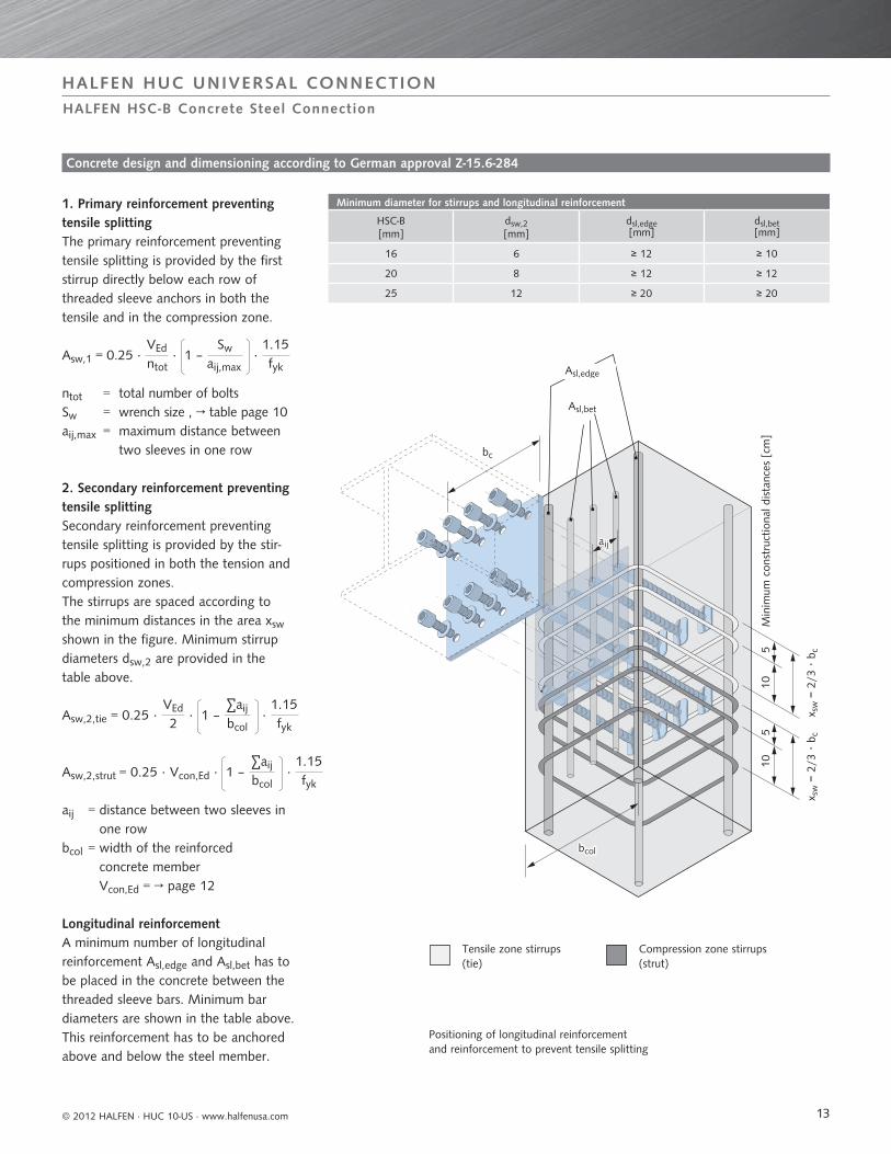
2. Secondary reinforcement preventing tensile splittingSecondary reinforcement preventingtensile splitting is provided by the stir-rups positioned in both the tension and compression zones.The stirrups are spaced according to the minimum distances in the area xsw shown in the figure. Minimum stirrup diameters dsw,2 are provided in the table above.
1. Primary reinforcement preventing tensile splittingThe primary reinforcement preventingtensile splitting is provided by the firststirrup directly below each row of threaded sleeve anchors in both the tensile and in the compression zone.
Asw,1 = 0.25 · VEd
ntot · 1 –
Sw aij,max
· 1.15fyk
ntot = total number of boltsSw = wrench size , → table page 10aij,max = maximum distance between two sleeves in one row
aij = distance between two sleeves in one row
bcol = width of the reinforced concrete memberVcon,Ed = → page 12
Longitudinal reinforcementA minimum number of longitudinal reinforcement Asl,edge and Asl,bet has to be placed in the concrete between the threaded sleeve bars. Minimum bar diameters are shown in the table above. This reinforcement has to be anchored above and below the steel member.
Asw,2,tie = 0.25 · VEd
2 · 1 –
∑aij
bcol ·
1.15fyk
Asw,2,strut = 0.25 · Vcon,Ed · 1 – ∑aij
bcol ·
1.15fyk
Positioning of longitudinal reinforcementand reinforcement to prevent tensile splitting
Concrete design and dimensioning according to German approval Z-15.6-284
HALFEN HSC-B Concrete Steel Connection
Tensile zone stirrups(tie)
Compression zone stirrups (strut)
14
dBr ≥ 10 ds
HALFEN HUC UNIVERSAL CONNECTION
© 2012 HALFEN · HUC 10-US · www.halfenusa.com
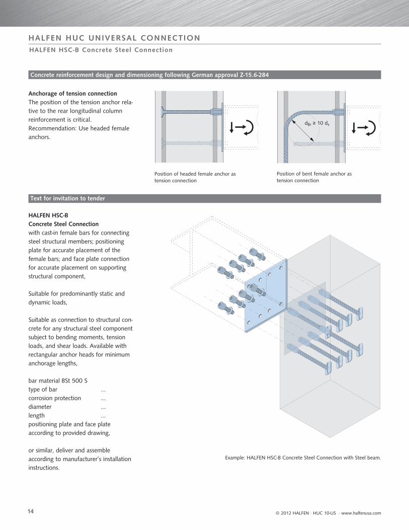
HALFEN HSC-B Concrete Steel Connection with cast-in female bars for connecting steel structural members; positioning plate for accurate placement of the female bars; and face plate connection for accurate placement on supporting structural component,
Suitable for predominantly static and dynamic loads,
Suitable as connection to structural con-crete for any structural steel component subject to bending moments, tension loads, and shear loads. Available with rectangular anchor heads for minimum anchorage lengths,
bar material BSt 500 S type of bar ...corrosion protection ...diameter ...length ...positioning plate and face plate according to provided drawing,
or similar, deliver and assembleaccording to manufacturer’s installation instructions.
Anchorage of tension connectionThe position of the tension anchor rela-tive to the rear longitudinal columnreinforcement is critical.Recommendation: Use headed female anchors.
Example: HALFEN HSC-B Concrete Steel Connection with Steel beam.
Position of headed female anchor astension connection
Position of bent female anchor astension connection
Text for invitation to tender
Concrete reinforcement design and dimensioning following German approval Z-15.6-284
HALFEN HSC-B Concrete Steel Connection
15
HALFEN HUC UNIVERSAL CONNECTION
© 2012 HALFEN · HUC 10-US · www.halfenusa.com
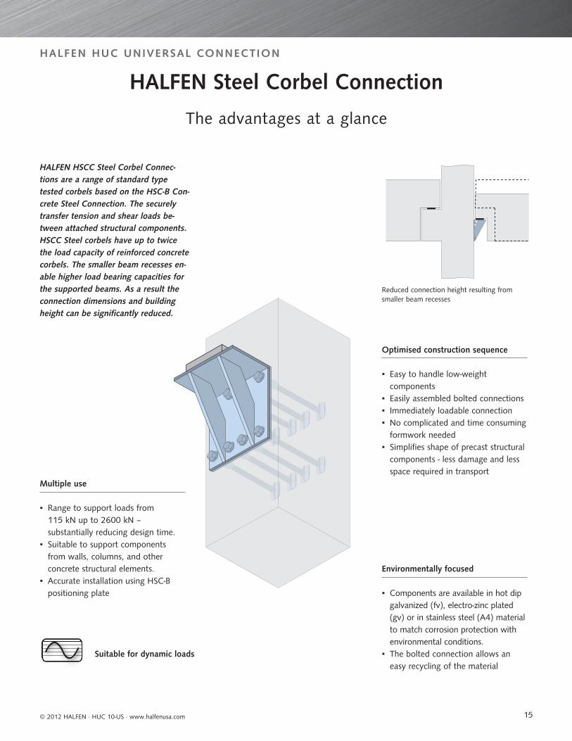
HALFEN HSCC Steel Corbel Connec-tions are a range of standard type tested corbels based on the HSC-B Con-crete Steel Connection. The securely transfer tension and shear loads be-tween attached structural components.HSCC Steel corbels have up to twice the load capacity of reinforced concrete corbels. The smaller beam recesses en-able higher load bearing capacities for the supported beams. As a result the connection dimensions and buildingheight can be significantly reduced.
Suitable for dynamic loads
Optimised construction sequence
▪ Easy to handle low-weight components
▪ Easily assembled bolted connections ▪ Immediately loadable connection ▪ No complicated and time consuming
formwork needed ▪ Simplifies shape of precast structural
components - less damage and less space required in transport
Environmentally focused
▪ Components are available in hot dip galvanized (fv), electro-zinc plated (gv) or in stainless steel (A4) material to match corrosion protection with environmental conditions.
▪ The bolted connection allows an easy recycling of the material
Reduced connection height resulting fromsmaller beam recesses
Multiple use
▪ Range to support loads from 115 kN up to 2600 kN – substantially reducing design time.
▪ Suitable to support components from walls, columns, and other concrete structural elements.
▪ Accurate installation using HSC-B positioning plate
HALFEN Steel Corbel Connection
The advantages at a glance
R -
037-
US
- 05/
11
04/
12©
201
2 H
ALF
EN G
mbH
, Ger
man
yap
plie
s al
so t
o co
pyin
g in
ext
ract
s.
CONTACT HALFEN WORLDWIDE
HALFEN has a g lobal network of Subs id iary Companies to ass is t you. The main contact in format ion for North Amer ica , Europe and As ia i s prov ided be low. For a fu l l l i s t of of f i ces p lease v is i t www.hal fen.com
HALFEN GmbH shall not accept liability for the accuracy of the information in this publication or for any printing errors.
HALFEN is also represented by distributors in Argentina, Australia, Azerbaijan, Belarus, Brazil, Bulgaria, Chile, Colombia, Croatia/Bosnia-Herzegovina/FYROM/Montenegro, Cyprus, Estonia, Greece, Hong Kong, Hungary, Indonesia, Ireland, Israel, Jordan, Kingdom of Saudi-Arabia, Latvia, Lebanon, Lithuania, Luxembourg, Malaysia, Malta, Mexico, New Zealand, Peru, Philippines, Republic of Kazakhstan, Romania, Russia, Serbia, Singapore, Slovenia, South Korea, Taiwan/ROC, Thailand, Turkey, Ukraine, United Arab Emirates, Uruguay, Vietnam
USA & Mexico HALFEN USA Inc.8521 F.M. 1976Converse, TX 78109
Phone: +1 800.423.9140 E-Mail: [email protected]: www.halfenusa.com
Fax: +1 888.277.1695
Fax: +86 - 10 5907 3218
Canada
China
UCC Industries International (Distributor)Units 12 & 13895 Sandy Beach RoadPickering, Ontario, L1W 3N7
Provinces of British Columbia and Alberta: Please contact HALFEN USA Inc.
HALFEN Construction Accessories Distribution Co.Ltd.Room 601 Tower D, Vantone CentreNo.A6 Chao Yang Men Wai StreetChaoyang District Beijing · P.R. China 100020
Phone: +1 905.831.7724E-Mail: [email protected]: www.ucci.ca
Phone: +86 - 10 5907 3200E-Mail: [email protected]: www.halfen.cn
Fax: +1 905.831.5872
Fax: +91 22.4202.4001
Fax: +49 2173 970-123
India
Germany
CRH India Management Services Pvt. Ltd.73-C, 3 North Avenue, Maker Maxity, Bandra-Kurla Complex, Bandra (East), Mumbai 400 051
HALFEN GmbHLiebigstrasse 14 40764 Langenfeld
Phone: +91 22.4202.4000E-Mail: [email protected]: www.halfen.in
Phone: +49 2173 970-0 E-Mail: [email protected]: www.halfen.de
www.halfen.com