HALFEN COLUMN SHOE SYSTEMdownloads.halfen.com/catalogues/de/media/approvals/reinforcement... · The...
33
HALFEN COLUMN SHOE SYSTEM CONCRETE Z HAB MH 13-E
-
Upload
phamnguyet -
Category
Documents
-
view
220 -
download
0
Transcript of HALFEN COLUMN SHOE SYSTEMdownloads.halfen.com/catalogues/de/media/approvals/reinforcement... · The...

HALFEN COLUMN SHOE SYSTEM
CONCRETE
Z HAB MH 13-E

GeneralCertifi cateof Approval
PUBLIC INSTITUTION
Approval Body for Construction Products and MethodsInspection Board for Construction TechnologyMember of the European Organisation forTechnical Approvals EOTAand the European Union of Agrément UEAtc
Phone: +49 30 78730-0Fax:+49 30 78730-320Email:[email protected]
Date:14th August 2012
Ref.No.:I 23-1.21.5-27/12
Approval No.:
Z-21.5-1758Valid from:
14th August 2012 to31th October 2013
Applicant:
Halfen GmbHLiebigstraße14, 40764 Langenfeld, GERMANY
Approved article:
Halfen - Anchor Bolt HAB MH
The above-mentioned product is hereby granted general certifi cate of approval.This general certifi cate of approval includes eleven pages and 19 appendices.This general certifi cate of approval replaces the general certifi cate of approvalno. Z-21.5-1758 issued October 28th 2003. This article fi rst gained General Building Approval on the 5th May 2004
Deutsches Institut für Bautechnik DIBt (DIBt)|An institute jointly supported by the federal and local governments.DIBt | Kolonnenstraße30L | D-10829Berlin | Phone +493078730-0 | Fax+ 493078730-320 | Email: [email protected] | www.dibt.de
Translation of the original German text not checked by the Deutsches Institut für Bautechnik
General certifi cate of approval
Z - 21.5 - 1758
Translation of the original German text not checked by the Deutsches Institut für Bautechnik
| October 28, 2008Page 2 of 11
I.GENERAL PROVISIONS
1. The general certifi cate of approval confi rms the usability or applicability of the object of licence in terms of the building regulations of the German federal states.
2. Please note; if the General Certifi cate of Approval requires specialist knowledge and exper-tise for persons responsible for production of building products and methods, according to federal regulations § 17 sect. 5 Musterbauordnung (German model Building regulations), this knowledge and experience may also be verifi ed by qualifi cations of similar status valid in other member states of the European Union. If appropriate this also applies for treaties pertaining to the European Economic Area EEA or other provided comparable qualifi cations as per bilateral agreements.
3. The general certifi cate of approval does not replace the statutory approvals, permits and certifi cates for the implementation of construction projects.
4. The general certifi cate of approval does not preclude the rights of third parties and, in particular, private proprietary rights.
5. Manufacturers and distributors of the object of the approval must submit copies of the general certifi cate of approval to the person using or implementing the object of approval, regardless of any supplementary regulations stipulated in the„ Special Provisions“, and must indicate that the general certifi cate of approval must be available for inspection at the place of use. The relevant authorities must be provided with copies of the general certifi cate of approval on request.
6. The general certifi cate of approval may only be published in its entirety. Publication of extracts of the general certifi cate of approval requires permission from the Deutsches Institut für Bautechnik. The texts and drawings of advertising material must not contradict the general certifi cate of approval. Translations of the general certifi cate of approval must bear the remark„ Translation of the original German text not checked by the Deutsches Institut für Bautechnik“.
7. The general certifi cate of approval is issued subject to revocation. The provisions of the general certifi cate of approval can be extended and amended, particularly to include current technical research.
14th August 2012
General certifi cate of approval
Z - 21.5 - 1758
Translation of the original German text not checked by the Deutsches Institut für Bautechnik
| October 28, 2008Page 3 of 11
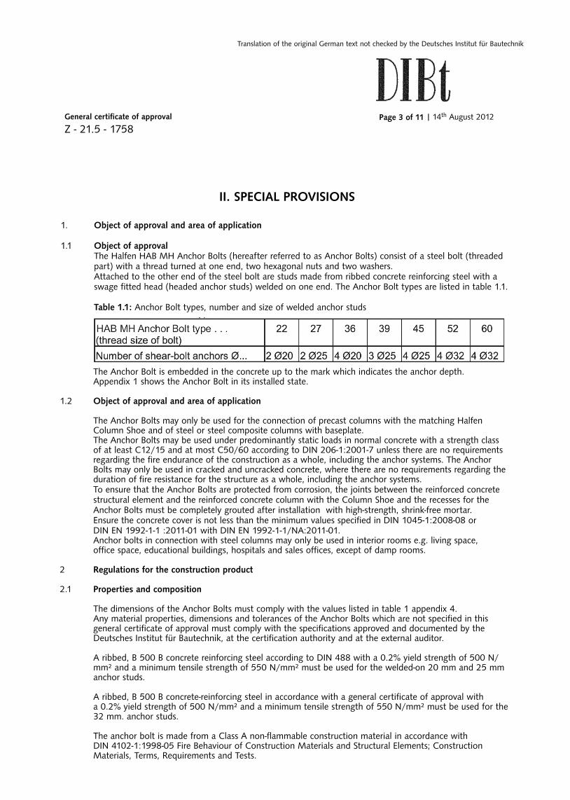
II. SPECIAL PROVISIONS
1. Object of approval and area of application
1.1 Object of approval The Halfen HAB MH Anchor Bolts (hereafter referred to as Anchor Bolts) consist of a steel bolt (threaded part) with a thread turned at one end, two hexagonal nuts and two washers. Attached to the other end of the steel bolt are studs made from ribbed concrete reinforcing steel with a swage fi tted head (headed anchor studs) welded on one end. The Anchor Bolt types are listed in table 1.1.
Table 1.1: Anchor Bolt types, number and size of welded anchor studs
The Anchor Bolt is embedded in the concrete up to the mark which indicates the anchor depth. Appendix 1 shows the Anchor Bolt in its installed state.
1.2 Object of approval and area of application
The Anchor Bolts may only be used for the connection of precast columns with the matching Halfen Column Shoe and of steel or steel composite columns with baseplate. The Anchor Bolts may be used under predominantly static loads in normal concrete with a strength class of at least C12/15 and at most C50/60 according to DIN 206-1:2001-7 unless there are no requirements regarding the fi re endurance of the construction as a whole, including the anchor systems. The Anchor Bolts may only be used in cracked and uncracked concrete, where there are no requirements regarding the duration of fi re resistance for the structure as a whole, including the anchor systems. To ensure that the Anchor Bolts are protected from corrosion, the joints between the reinforced concretestructural element and the reinforced concrete column with the Column Shoe and the recesses for theAnchor Bolts must be completely grouted after installation with high-strength, shrink-free mortar. Ensure the concrete cover is not less than the minimum values specifi ed in DIN 1045-1:2008-08 or DIN EN 1992-1-1 :2011-01 with DIN EN 1992-1-1/NA:2011-01.
Anchor bolts in connection with steel columns may only be used in interior rooms e.g. living space, offi ce space, educational buildings, hospitals and sales offi ces, except of damp rooms.
2 Regulations for the construction product
2.1 Properties and composition
The dimensions of the Anchor Bolts must comply with the values listed in table 1 appendix 4. Any material properties, dimensions and tolerances of the Anchor Bolts which are not specifi ed in this general certifi cate of approval must comply with the specifi cations approved and documented by the Deutsches Institut für Bautechnik, at the certifi cation authority and at the external auditor. A ribbed, B 500 B concrete reinforcing steel according to DIN 488 with a 0.2% yield strength of 500 N/
mm² and a minimum tensile strength of 550 N/mm² must be used for the welded-on 20 mm and 25 mm anchor studs.
A ribbed, B 500 B concrete-reinforcing steel in accordance with a general certifi cate of approval with a 0.2% yield strength of 500 N/mm² and a minimum tensile strength of 550 N/mm² must be used for the 32 mm. anchor studs. The anchor bolt is made from a Class A non-fl ammable construction material in accordance with DIN 4102-1:1998-05 Fire Behaviour of Construction Materials and Structural Elements; Construction Materials, Terms, Requirements and Tests.
14th August 2012

General certifi cate of approval
Z - 21.5 - 1758
Translation of the original German text not checked by the Deutsches Institut für Bautechnik
| October 28, 2008Page 4 of 11
2.2 Packaging, Storage and Labelling
2.2.1 Packaging and Storage The Anchor Bolt must only be packaged and supplied as one fi xing unit.
2.2.2 Labelling
The manufacturer must label the packaging, packaging leafl et or delivery note with the conformity symbol (Ü symbol) in accordance with the symbol of conformity regulations of the German federalstates. The manufacturer‘s identifi cation mark, the approval number and a full description of the Anchor Bolts must also be provided. The label may only be applied after the requirements according to section 2.3 have been fulfi lled.The anchor bolts must be labelled according to their type and thread diameter, e.g. HAB MH 22. Each anchor bolt must be stamped with the manufacturer‘s identifi cation mark and the thread diameter in accordance with appendix 4. The depth of anchorage is indicated by the end of the thread.
2.3 Proof of conformity
2.3.1 General information
Compliance of the Anchor Bolt with the provisions of this general certifi cate of approval must be confi rmed for each manufacturing works with a certifi cate of conformity based on an in-house production check and regular external auditing including initial testing of the Anchor Bolt according to the followingprovisions. In order to issue a certifi cate of conformity and for the external auditing including the product tests that have to be carried out in this regard, the manufacturer of the Anchor Bolts must notifi y a recognized certifi cation body and an auditor which is recognized for this purpose. To indicate that the product has been awarded a conformity certifi cate (Übereinstimmungszertifi kat), the manufacture is required to identify the product with the conformity U Symbol (Übereinstimmungszeichen) with reference to the application.In addition, a copy of the initial test report must be submitted to the Deutsches Institut für Bautechnik for information purposes.
2.3.2 In-house production check
An in-house production check must be set up and carried out at each manufacturing plant. An in-house production check is understood to mean a system of continual monitoring of the production process which must be set up by the manufacturer in order to ensure that the construction products manufactured comply with the provisions of this general certifi cate of approval.
The inspection and supervision plan on record at the Deutsches Institut für Bautechnik and at the external auditor is authoritative for the scope, type and frequency of the in-house production check. The results of the in-house production check must be documented and evaluated. The records must contain at least the following details: – Name of the construction product or raw material and the components – Type of inspection or test – Date of manufacturing and testing of the construction product, raw material or components. – Result of the inspection and tests and, where applicable, comparison with the requirements. – Signature of the person responsible for the in-house production check.
14th August 2012

General certifi cate of approval
Z - 21.5 - 1758
Translation of the original German text not checked by the Deutsches Institut für Bautechnik
| October 28, 2008Page 5 of 11
These records must be archived for at least fi ve years and made available to the external auditor selected for third party monitoring. They must be submitted on request to the Deutsches Institut für Bautechnik and the highest responsible building supervisory authority.If the test result is unsatisfactory, the manufacturer must immediately take the necessary action to eliminate the defect. Construction products that do not satisfy the requirements must be handled so as to prevent them from being confused in any way with parts which do conform. After the defect has been eliminated, the relevant test must be repeated without delay where this is technically feasible and necessary to prove that the defect has been eliminated.
2.3.3 External auditing
The in-house production check must be inspected by an external auditor at each manufacturing location on a regular basis at least once a year. The inspection and supervision plan on record at the Deutsches Institut für Bautechnik and the external auditor are authoritative for the scope, type and frequency of the external auditing. The certifi cation and external auditing results must be archived for at least fi ve years. They must be submitted on request by the certifi cation body or auditor to the Deutsches Institut für Bautechnik and the highest responsible building supervisory authority.
3 Provisions for design and dimensioning
3.1 Design
3.1.1 General information
The anchor connections must be designed according to standard engineering principles. Calculations and construction designs which can be tested and which include the position of the anchor connections and possible dimensional deviations must be prepared, taking the intended loads to be anchored into consideration.
Unless otherwise defi ned; for design, detailed planning, calculation of required dimensions and sizesDIN 1045-1 or DIN EN 1992-1-1 applies for design and calculation of the structural system as a whole.Mixing both technical building standards is not permissibleDIN EN 1992-1-1 applies only when used in conjunction with DIN EN 1992-1-1/NA.
Only groups consisting of four, six or eight Anchor Bolts in accordance with appendix 4 are permitted. The terms and symbols which are used here are explained in appendices 5 and 6.
The anchor connection may only be dimensioned as Anchor Bolt group for precast concrete columns,if the Column Shoe recesses for the Anchor Bolts are completely grouted with a high-strength, non-shrink mortar and the eff ective loads are transferred via the bond into the individual Anchor Bolts of the group. Only Anchor Bolts of the same diameter and length may be used in any one group of Anchor Bolts.
The internal forces of the Anchor Bolts must be calculated from forces and moments acting on the anchor plate of the Column Shoes according to the theory of elasticity. The following assumptions must be made:
a) The anchor plate remains fl at under the stress of the internal forces.
b) The rigidity is the same for all Anchor Bolts. It corresponds with the rigidity of the steel cross section.
c) The modulus of elasticity of the concrete is assumed as Ec= 30,000 N/mm²
Anchor Bolts with a drill hole clearance in the direction of the transverse load, exceeding the values of table 3.1 (e.g. slotted holes) may not be taken in consideration for transverse load bearing.
For anchor connections with a drill hole clearance in the direction of the transverse load, smaller than the values of table 3.1, only the Anchor Bolts near to the edge may be taken into consideration for transverse load bearing.
14th August 2012

General certifi cate of approval
Z - 21.5 - 1758
Translation of the original German text not checked by the Deutsches Institut für Bautechnik
| October 28, 2008Page 6 of 11
All Anchor Bolts take up transverse loads only, if
– the clearance of the drill hole in the direction of the transverse load is smaller than the values of table 3.1 and
– the anchor connection has a large distance to the edge (c ≥ 10hef ) and – steel failure or concrete failure is decisive on the side facing away from the load direction.
Table 3.1 Diameter of the drill hole in the anchor base plate
14th August 2012
3.1.2 Minimum centre spacings and edge distances The centre spacings and distances from the edge must not be less than the minimum values listed in table 1, appendix 4.
3.1.3 Minimum thickness of the structural element The required thickness hmin of the structural element results from the anchoring depth l2 according to appendix 4 and the required concrete cover cnom
hmin = l2 + cnom (3.1)
l2 = Installation depth acc. to appendix 4, table 1
cnom = Required concrete cover acc. to DIN 1045-1:2008-08 or DIN EN 1992-1-1 :2011-01 with DIN EN 1992-1-1/NA:2011-01
3.2 Dimensioning
3.2.1 General information The anchor connections must be dimensioned according to engineering methods with partial safety factors as described below. Proof of the direct local transfer of loads into the concrete is given. The transfer of the loads to be taken up into the structural element must be proven. Stresses which can be generated in the anchor or the connected structural component by constricted deformation (e.g. due to temperature changes) must be considered.
3.2.2 Required proofs It must be proved that the design value of the eff ect (stress) Sd does not exceed the design value of the resistance (load capacity) Rd Sd ≤ Rd Sd = Design value of the stress Rd = Design value of the resistance For the simplest case (constant load) and a variable load acting in same direction), the following applies for the design values of the eff ects: Fd = Sd = γG · Gk + γQ · Qk (3.3a) Gk; Qk = Characteristic value of a constant or a variable effect according to the applicable standards for design loads γG; γQ = Partial safety factor for constant or variable effects
drill hole

General certifi cate of approval
Z - 21.5 - 1758
Translation of the original German text not checked by the Deutsches Institut für Bautechnik
| October 28, 2008Page 7 of 11
The design value of the resistance for the proof of the load capacity results from the characteristic load capacity of the Anchor Bolt anchoring with: Rd = Rk/γM (3.3b)
Rk = Characteristic value of the resistance (load capacity, e.g. NRk or VRk). This value must be calculated for the individual causes of failure by the calculation methods specifi ed in the appendices 5 to 20 respectively according to the indicated method. γM = Partial safety factor for the resistance of the material.
The required proofs of the load capacity at tensile or perpendicular loads are listed in the following tables 3.2 and 3.3.
Table 3.2 Required proofs for tensile loads
Table 3.3. Required proofs for transverse loads
1 This proof is not required, if the actual edge distance c is > 0.5 hef in both directions.2 This proof is not required, if a restraint reinforcement acc. appendix 13 is provided (proofs according to 4b above).
1 This proof is not required, if a restraint reinforcement according to appendices 19 or 20 is provided (proofs according to 4b above)
14th August 2012

General certifi cate of approval
Z - 21.5 - 1758
Translation of the original German text not checked by the Deutsches Institut für Bautechnik
| October 28, 2008Page 8 of 11
In the presence of combined tensile and transverse loads (diagonal tensile load), the following interaction condition must be observed:
The highest value from the individual causes of failure must be used for the ratios NSd /NRd and VSd /VRd in each case. The value α in the equation (3.4) must be taken as 1.5 for the anchor connection without restraint reinforcement respectively for the anchor connection with restraint reinforcement for tensional and transverse loads. If for the dimensioning a restraint reinforcement is used only for tensile loads (sect. 3.2.4.2) or only for transverse loads at the edge (sect. 3.2.4.3), the value α must be taken as 2/3. If the Anchor Bolts at precast concrete columns are subject to transverse loads, the total transverse load must be transferred into the anchoring substrate by bending on the Anchor Bolts. Considering a bending load on the Anchor Bolts can only be omitted, if all the following conditions apply:
- the material of the structure to be connected is metal, and the structure is tightened against the concrete without any intermediate layer and - the hole diameter of the structure to be connected does not exceed the values listed in table 3.1.
3.2.3 Partial safety factors In general, for constant or variable eff ects, the partial safety factors of the eff ects for the proof of the load- bearing capacity are: γG = 1.35 or γQ = 1.5 The partial safety factors for material resistance for the proof of the load bearing capacity must be taken as follows: γMc = 1.5 Concrete failure (pull-out or concrete blow-out) γMs= 1.5 Steel failure of the Anchor Bolts (centric tension) γMs = 1.25 Steel failure of the Anchor Bolts (perpendicular or bending load) γMh =1.15 Steel failure of the restraint reinforcement Partial safety factors of γG, γQ and γM of 1.0 must be used for the proof of fi tness for use.
3.2.4 Reinforcement3.2.4.1 Minimum reinforcement (splitting) A minimum reinforcement with the following cross section As must be provided in order to prevent the concrete structural element from splitting:
∑Nsd = Sum of tensile loads in Anchor Bolts subjected to tensile stress under the design value for the eff ects fyk = Yield strength of the reinforcement
γMs,re = 1.15 The above mentioned verifi cation can be omitted if at least one crosswise reinforcement (B 500 B) diameter 8 / 15 is provided in the area of the Anchor Bolt anchorings.
(3.4)
14th August 2012

General certifi cate of approval
Z - 21.5 - 1758
Translation of the original German text not checked by the Deutsches Institut für Bautechnik
| October 28, 2008Page 9 of 11
In fl at load-bearing structures, splitting tensile reinforcement is necessary in both directions. With structural elements which are predominantly subject to tensile stress, the reinforcement must be arranged on both sides of the cross section, and with structural elements which are predominantly under bending stress the reinforcement must be arranged on the side which is tensile stressed. The reinforcement should consist of at least three bars spaced s ≤150 mm apart and must be anchored outside the anchor connection with an anchoring length of lb in accordance with DIN 1045-1:2008-08 or Ib,rqd according to DIN EN 1992-1- 1:2011-01 with DIN EN 1992-1-1/NA:2011-01. With linear load-bearing structures, the shear reinforcement need only be arranged in one direction. With anchor connections at the edges of the structural element, this reinforcement must also be provided in the form of edge reinforcement with appropriate restraint reinforcement.
3.2.4.2 Restraint reinforcement for tensile loads
Proof for concrete blow-out failure acc. to appendices 10 to 12 can be omitted under the condition, that for anchor connections with tensile loads a restraint reinforcement is provided according to fi gure 8, appendix 13. The calculation of the characteristic steel load bearing capacity NRk,re and the design resistance NRd,a of the restraint reinforcement is given in appendix 13. If the restraint reinforcement is not connected to the Anchor Bolt, a surface reinforcement must be calculated and installed according to the strut and tie model. The restraint reinforcement must be anchored in the concrete outside of the fracture cone with an anchoring length lb,net acc. to DIN 1045-1:2008-08. or Ib,d according to DIN EN 1992-1-1:2011-01 with DIN EN 1992-1-1/NA:2011-01 The minimum anchoring length lb,min and the maximum bar diameter according to appendix 13 must be observed. In case of non-centric tensile loads the reinforcement designed for the Anchor Bolt with the highest load must be provided for all Anchor Bolts.
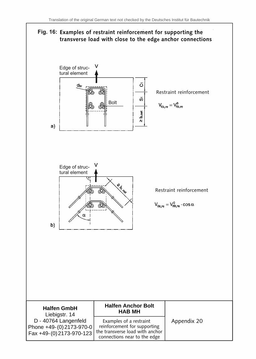
3.2.4.3 Restraint reinforcement for transverse loads at the edge A proof for concrete edge blow-out failure acc. to appendices 16 to 18 can be omitted under the condition, that for anchor connections at the edge, of the element and transverse loads towards the edge a restraint reinforcement is provided according to fi gures 15 and 16, appendices 19 and 20.
The characteristic transverse load capacity V0Rk,re of a bar (B 500 B) of the restraint reinforcement is
shown in table 8, appendix 19. The restraint reinforcement must be anchored in the concrete on the side facing away from the load direction with an anchoring length lb,net acc. to DIN 1045-1:2008-08 or Ib,d according to DIN EN 1992-1- 1:2011-01 with DIN EN 1992-1-1/NA:2011-01. In case of non-centric transverse loads the reinforcement designed for the Anchor Bolt with the highest load must be provided for all Anchor Bolts.
3.2.5 Proof of the structural element load-bearing capacity according to DIN 1045-1:2008-08 or DIN EN 1992-1-1 :2011-01 with DIN EN 1992-1-1/NA:2011-01
It must be proved that the shear stresses caused by the bolt loads VSd,a do not exceed the value 0.4 VRd,ct (VRd,ct = design value of the resistance for transverse stress acc. to DIN 1045-1:2008-08), design value for shear force resistance according to DIN EN 1992-1-1 :2011-01 with DIN EN 1992-1-1 INA:2011-01).
For the calculation of Vsd,a , the Anchor Bolt loads are to be considered as point loads with a load direction width of t1 = st1 + 2hef and t2 = st2 + 2hef , assuming st1 (st2) = centre spacing between the outer bolts of a group of bolts in direction 1 (2). The eff ective width is to be calculated according to the elasticity theory. This proof can be omitted, if one of the following conditions is present (see also table 3.4):
14th August 2012
General certifi cate of approval
Z - 21.5 - 1758
Translation of the original German text not checked by the Deutsches Institut für Bautechnik
| October 28, 2008Page 10 of 11
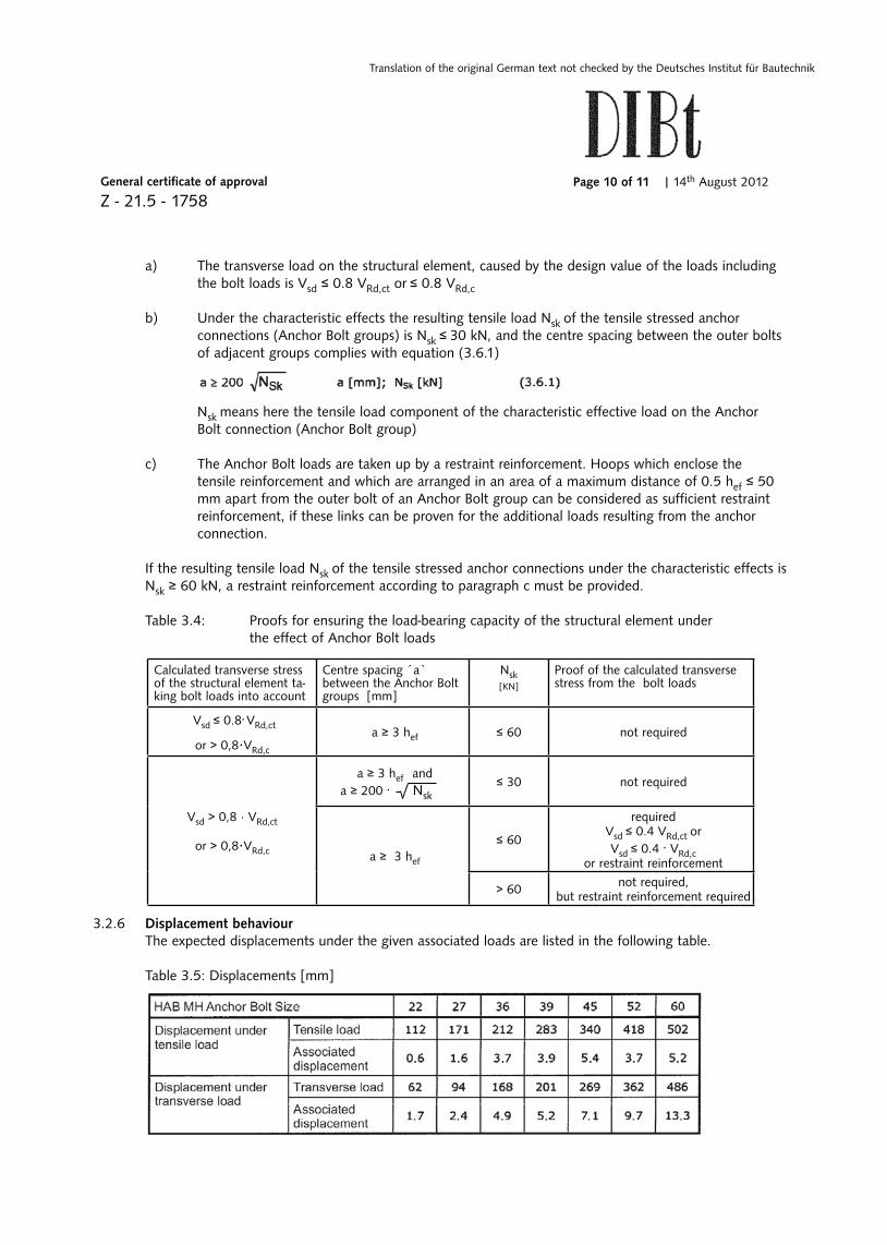
a) The transverse load on the structural element, caused by the design value of the loads including the bolt loads is Vsd ≤ 0.8 VRd,ct or ≤ 0.8 VRd,c
b) Under the characteristic eff ects the resulting tensile load Nsk of the tensile stressed anchor connections (Anchor Bolt groups) is Nsk ≤ 30 kN, and the centre spacing between the outer bolts of adjacent groups complies with equation (3.6.1)
Nsk means here the tensile load component of the characteristic eff ective load on the Anchor Bolt connection (Anchor Bolt group)
c) The Anchor Bolt loads are taken up by a restraint reinforcement. Hoops which enclose the tensile reinforcement and which are arranged in an area of a maximum distance of 0.5 hef ≤ 50 mm apart from the outer bolt of an Anchor Bolt group can be considered as suffi cient restraint reinforcement, if these links can be proven for the additional loads resulting from the anchor connection.
If the resulting tensile load Nsk of the tensile stressed anchor connections under the characteristic eff ects is Nsk ≥ 60 kN, a restraint reinforcement according to paragraph c must be provided.
Table 3.4: Proofs for ensuring the load-bearing capacity of the structural element under the eff ect of Anchor Bolt loads
3.2.6 Displacement behaviour The expected displacements under the given associated loads are listed in the following table.
Table 3.5: Displacements [mm]
Calculated transverse stress of the structural element ta-king bolt loads into account
Centre spacing ´a` between the Anchor Bolt groups [mm]
Nsk[KN]
Proof of the calculated transverse stress from the bolt loads
Vsd ≤ 0.8. VRd,ct
or > 0,8·VRd,c
a ≥ 3 hef ≤ 60 not required
Vsd > 0,8 · VRd,ct
or > 0,8·VRd,c
a ≥ 3 hef and
a ≥ 200 . Nsk≤ 30 not required
a ≥ 3 hef
≤ 60
requiredVsd ≤ 0.4 VRd,ct orVsd ≤ 0.4 . VRd,c
or restraint reinforcement
> 60 not required, but restraint reinforcement required
14th August 2012

General certifi cate of approval
Z - 21.5 - 1758
Translation of the original German text not checked by the Deutsches Institut für Bautechnik
| October 28, 2008Page 11 of 11
4 Provisions for execution
4.1 Installation of anchor connections
The anchor connections must be installed according to the compulsory design drawing. The design draw-ings must show the exact position and the execution data (position, size and lengths of the Anchor Bolts) of the anchor connections. The anchor connections must be fastened to the formwork so that they are not displaced when the reinforcement is placed and the concrete is poured and compacted. During concreting, it must be ensured that the concrete is particularly well compacted under the heads of the anchor bolts.After installation, the recesses for the nuts and the concrete –steel joint between the precast reinforced concrete column and the corresponding bolt connection must be fi lled with grout. The grout must be according to DAfstb guide-lines “composition and application of cement based pouring concrete and pouring grout” and must be fl ush with the column.
The maximum installation moment Tinst acc. to table 1, appendix 4, may not be exceeded, in particular with the fastening of the base plate according to appendix 3. The use of a torque wrench is not required for Anchor Bolt load bearing capacity.
4.2 Checking execution of work
The contractor who is responsible for anchoring the Anchor Bolts or the construction supervisor assigned by him or a competent representative of the construction supervisor must be present on site while the anchor connections are being installed. He must ensure that the work is executed properly. In particular, he must check the design and position of the anchor connections as well as any restraint reinforcement. Records must be available on site during the construction period and must be submitted to authorised supervisory personnel on request. After completion of the work, the records must be archived by the contractor as with the delivery notes for at least fi ve years.
4.3 Fitting the Column Shoe
The matching Halfen Column Shoes must be fi tted in accordance with the installation instructions from Halfen. The assembly joint between the concrete structural element and the Column Shoe as well as the recesses for the nuts must be completely grouted afterwards with a high-strength, non-shrink mortar.
Feistel
14th August 2012
Translation of the original German text not checked by the Deutsches Institut für Bautechnik
Halfen GmbHLiebigstr. 14
D - 40764 LangenfeldPhone +49- (0) 2173-970-0Fax +49- (0) 2173-970-123
to GeneralCertificate of ApprovalZ-21.5 - 1758dated October 28, 2008
Halfen Anchor BoltHAB MH
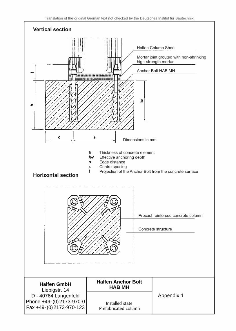
Vertical section
Halfen Column Shoe
Mortar joint grouted with non-shrinkinghigh-strength mortar
Anchor Bolt HAB MH
Dimensions in mm
Thickness of concrete elementEffective anchoring depthEdge distanceCentre spacingProjection of the Anchor Bolt from the concrete surface
Precast reinforced concrete column
Concrete structure
Horizontal section
Appendix 1
Installed state
Appendix 1
Prefabricated column

Translation of the original German text not checked by the Deutsches Institut für Bautechnik
Halfen GmbHLiebigstr. 14
D - 40764 LangenfeldPhone +49- (0) 2173-970-0Fax +49- (0) 2173-970-123
to GeneralCertificate of ApprovalZ-21.5 - 1758dated October 28, 2008
Halfen Anchor BoltHAB MH
Thickness of concrete elementEffective anchoring depthEdge distanceCentre spacing
of the Anchor Bolt from the concrete surfaceProjection
Base plate
Concrete structure
Vertical section
Halfen Column Shoe
Mortar joint grouted with non-shrinkinghigh-strength mortar
Anchor Bolt HAB MH
Horizontal section
hhcsf
ef
Dimensions in mm
Steel column
Anchor Bolt HAB MH
Appendix 2
Installed statesteel column with counter
nut screw connection
Appendix 2
Steel column
To be used in dry interior rooms only

Translation of the original German text not checked by the Deutsches Institut für Bautechnik
Halfen GmbHLiebigstr. 14
D - 40764 LangenfeldPhone +49- (0) 2173-970-0Fax +49- (0) 2173-970-123
to GeneralCertificate of ApprovalZ-21.5 - 1758dated October 28, 2008
Halfen Anchor BoltHAB MH
hhcsf
ef
Thickness of concrete elementEffective anchoring depthEdge distanceCentre spacing
of the Anchor Bolt from theconcrete surfaceProjection
Base plate
Concrete structure
Horizontal section
Steel column
(Example)
Dimensions in mm
Vertical section
Anchor Bolt HAB MH
To be applied in dry interior rooms .only
Appendix 3
Installed statesteel column with counter
nut screw connection
Appendix 3Installed statesteel column withoutnut screw connection
To be used in dry interior rooms only

Translation of the original German text not checked by the Deutsches Institut für Bautechnik
Halfen GmbHLiebigstr. 14
D - 40764 LangenfeldPhone +49- (0) 2173-970-0Fax +49- (0) 2173-970-123
to GeneralCertificate of ApprovalZ-21.5 - 1758dated October 28, 2008
Halfen Anchor BoltHAB MH
Figure 1: Symbols used
Top viewbolt
Identification
Anchor sizes, dimensions and installation values
Mark for theanchoring depth/end of the thread
Anchor Bolt identification
Total lengthNumber of anchor studsInstallation depthBolt protrusion / thread lengthMinimum spacingMinimum edge distanceEffective anchoring lengthAnchoring lengthDiameter anchor barsDiameter headed studDiameter threadBolt tensional areaBase areamax. installation torque
MaterialsConcr.reinf.steelThreaded partWashersHex-head nuts
Headed stud diam.20 to 25mm: B 500 B, DIN 488-2:2009-08, diam.32: B 500 B according toS690, DIN EN 10023-6:2005-02 or Imacro M General Certificate of ApprovalDIN EN ISO 7089:2000-11, S355J0 acc. to DIN EN 10025-2:2005-04Strength grade 8 acc. to DIN EN ISO 4032:2001-03 and DIN EN 20898-2:1994-02
Figure 2: Approved arrangements of Anchor Bolts
Appendix 4
Anchor sizes,installation dataand dimensions
Appendix 4
10025

Translation of the original German text not checked by the Deutsches Institut für Bautechnik
Halfen GmbHLiebigstr. 14
D - 40764 LangenfeldPhone +49- (0) 2173-970-0Fax +49- (0) 2173-970-123
to GeneralCertificate of ApprovalZ-21.5 - 1758dated October 28, 2008
Halfen Anchor BoltHAB MH
Indices
S = Stress
R = Resistance
k = Characteristic value
d = Design value
s = Steel
c = Concrete
cb = Local concrete blow-out (blow-out failure)
cp = Concrete blow-out on the side facing away from the load (pryout failure)
p = Pull-out failure
Effects and resistances
F = Force (resultant force)
N = Normal force (positive tensile force)
V = Transverse force
M = Bending moment
F (N ; V ; M ) = Characteristic value of the stress (normal force, transverseforce, bending moment)
Sk Sk Sk Sk
F (N ; V ; M ) = Design value of the stress (normal force, transverseforce, bending moment)
F (N ; V ; M ) = Characteristic value of the resistance (load bearing capacity:normal force, transverse force, bending moment)
F (N ; V ; M ) = Design value of the resistance (load bearing capacity: normalforce, transverse force, bending moment)
N (V ) = Design value of the effective tensile force (transverse force)of the Anchor Bolt with the highest stress
N (V ) = Design value of the effective resulting force of all tensilestressed (transverse stressed) bolts
Sd Sd Sd Sd
Rk Rk Rk Rk
Rd Rd Rd Rd
hSd
hSd
gSd
gSd
Appendix 5
Terms and symbols
Appendix 5

Translation of the original German text not checked by the Deutsches Institut für Bautechnik
Halfen GmbHLiebigstr. 14
D - 40764 LangenfeldPhone +49- (0) 2173-970-0Fax +49- (0) 2173-970-123
to GeneralCertificate of ApprovalZ-21.5 - 1758dated October 28, 2008
Halfen Anchor BoltHAB MH
a = Distance between the outer Anchor Bolts of neighbouring groups ofbolts in Direction 1
1
a = Distance between the outer Anchor Bolts of neighbouring groups ofbolts in Direction 2
b = Width of the concrete structural component
c = Distance from the edge in Direction1, with anchor connections undertransverse stress, c is the distance from the edge in the direction ofthe load (see Figure 3)
c = Distance from the edge in Direction2, Direction 2 ist perpendicular toDirection 1
c = Minimum permitted distance from the edge
s = Centre spacing within a group of Anchor Bolts in Direction 1
s = Centre spacing within a group of Anchor Bolts in Direction 2
s = Minimum permitted centre spacing
d = Diameter of the shaft of the anchor stud
d = Diameter of the head of the anchor stud
d = Diameter of the thread of the central anchor rod
h = Effective anchoring depth
h = Thickness of the concrete structural component
h = Minimum thickness of the concrete structural component
l = Length of the Anchor Bolt in the concrete structural element
2
1
1
2
min
1
2
min
1
2
3
ef
min
2
Figure 3: Concrete element, centre spacing and distances from the edge
a) Anchor Bolts under tensile load b) Anchor Bolts under transverse loadin an anchor connection near to the edge
Transverse load not perpendicular to the edge,see Figure 13
Direction
Direction 1 an 2 dependson the direction of thetransverse load
Anchor Bolt connection characteristics
Appendix 6
Anchor Boltconnection characteristics
Appendix 6
direction
direction
direction
direction directiondirection
direction
direction
is perpendicular to
and
fi gure
fig. 3)

Translation of the original German text not checked by the Deutsches Institut für Bautechnik
Halfen GmbHLiebigstr. 14
D - 40764 LangenfeldPhone +49- (0) 2173-970-0Fax +49- (0) 2173-970-123
to GeneralCertificate of ApprovalZ-21.5 - 1758dated October 28, 2008
Halfen Anchor BoltHAB MH
Characteristic resistance values for the proofof the load bearing capacity under tensile stress
Anchor Bolt size
Table 3: Characteristic tensile load bearing capacity N of ananchor bolt at steel failure in kN
Rk,s
Characteristic tensile loadbearing capacity N [kN]Rk,s
Characteristic tensile load bearing capacity N of ananchor bolt at pull-out failure in kN
Rk,p
Anchor Bolt size
Factor of the tensile load bearing capacity N of anat pull-out failure depending from the concrete strength
Ψ Rk,p
Concrete grade
Increasing factor Ψ
Characteristic tensile loadbearing capacity in concretegrade C20/25 at pull-outN [kN]Rk,s
Appendix 7
Characteristic tensile load bearing capacity with steel
failure and at pull-out
Appendix 7

Translation of the original German text not checked by the Deutsches Institut für Bautechnik
Halfen GmbHLiebigstr. 14
D - 40764 LangenfeldPhone +49- (0) 2173-970-0Fax +49- (0) 2173-970-123
to GeneralCertificate of ApprovalZ-21.5 - 1758dated October 28, 2008
Halfen Anchor BoltHAB MH
Local concrete blow-out with anchor connections near the edge
The factor of influence s,Nb takes into account the disruption of the tensile state in theconcrete at the corner of the structural element.
�
The proof for local concrete blow-out near the edge of the structural element must always becarried out, if the actual edge distance is c 0.5 h in one direction. In the following theindividual factors of the Equation (3.7) are specified:
≤ ef
The characteristic tensile load capacity of an Anchor Bolt or an Anchor Bolt group with localconcrete blow-out near the edge is
The initial value of the characteristic load capacity of a bolt is:
with
Distance to the edgeBase area of the anchor heads of an Anchor Bolt, see Table 1, App. 4
may be assessed with at most 60 N/mm².
The influence of the centre spacings and edge distances on the characteristic load capacity isconsidered with the ratio
16c ²; projected area of an Anchor Bolt (on one lateral side of the concrete).Thereby the blow-out body is assumed as a pyramid with the peak at the centreof the bolt head, with a height c and a length of one side of the base 4 c (seeAppendix 9, Figure 4).
1
1 1
actual projected area (on the lateral side of the concrete).
When calculating, the blow-out body of the Anchor Bolt is to be idealised asdescribed above, and the interference of the projected areas must beconsidered. Example for the calculation of the projected area: see Appendix9, Figure 5.
For securing the corner of the structural element a corner reinforcement must beprovided, which must be dimensioned for the tensile load of the bolt.
The factor of influence g,Nb takes into account the influence of the base areas of the individualanchoring devices within a group anchoring.
�
n = number of Anchor Bolts under tensile load, arranged in a line parallel to theedge of the structural element.
The factor of influence ec,Nb takes into account a non-centric tensile load on the anchoringarranged in a line.
�
e = „inner“ non-centricity of the bolts under tensile load(see also Appendix 12, d) )
n
Appendix 8
Characteristic tensile load bearing capacity with local concrete failure at the edge
Appendix 8
equation
at max. 60 N/mm²
an anchoring group.
an anchoring group.
( see also equation (3.8c))
table 1
figure 4).
figure 5).

Translation of the original German text not checked by the Deutsches Institut für Bautechnik
Halfen GmbHLiebigstr. 14
D - 40764 LangenfeldPhone +49- (0) 2173-970-0Fax +49- (0) 2173-970-123
to GeneralCertificate of ApprovalZ-21.5 - 1758dated October 28, 2008
Halfen Anchor BoltHAB MH
Figure 4: Idealised concrete blow-out
Figure 5: Example for a local concrete blow-out at the edge
Section (Fig. 4) Lateral view (Fig. 4)
Section (Fig. 5) Plan view (Fig. 5)
Appendix 9
Characteristic tensile load bearing capacity with local concrete failure at the edge
Appendix 9

Translation of the original German text not checked by the Deutsches Institut für Bautechnik
Halfen GmbHLiebigstr. 14
D - 40764 LangenfeldPhone +49- (0) 2173-970-0Fax +49- (0) 2173-970-123
to GeneralCertificate of ApprovalZ-21.5 - 1758dated October 28, 2008
Halfen Anchor BoltHAB MH
The factor of influence takes into account the disruption of the rotationally symmetricstate of stress in the concrete due to the edges of the structural element. With severaledges of the structural element (e.g. with anchor connections at the corner of the structuralelement or in a narrow structural element), the smallest distance to the edge c must be usedin Equation (3.8b).
�s,N
Concrete blow-out
The characteristic tensile load capacity of an Anchor Bolt or an Anchor Bolt group withconcrete blow-out is:
The individual factors of the Equation (3.8) are shown in the following:
a) The initial value of the characteristic tensile load-bearing capacity of a bolt in theconcrete is:
with
can be set as a miximum of 60 N/mm²
b) The effect of the centre spacings and edge distances on the characteristic load-bearingcapacity is taken into account by the ratio A /A :c,N
0c,N
area of the blow-out body of a single bolt with large centre spacing anddistance from the edge on the concrete surface. The blow-out body isidealised as a pyramid of height h and length of side of base 3h (seeAppendix 11, Fig. 6)
ef ef
available area of the blow-out body of the anchor connection on theconcrete surface. It is limited by the overlapping of the individual blow-outbodies of neighbouring anchorings (s 3h ) and by the edges of thestructural elements
≤ ef
(c 1.5h ).Example for the calculation of A : see Appendix 11, Fig. 7.
≤ ef
c,N
c)
Appendix 10
Characteristic tensileload bearing capacity in thecase of concrete bow-out
Appendix 10
equation
maximum
equation
blow-out
fig. 6
fig. 6

Translation of the original German text not checked by the Deutsches Institut für Bautechnik
Halfen GmbHLiebigstr. 14
D - 40764 LangenfeldPhone +49- (0) 2173-970-0Fax +49- (0) 2173-970-123
to GeneralCertificate of ApprovalZ-21.5 - 1758dated October 28, 2008
Halfen Anchor BoltHAB MH
Figure 6: Idealised concrete blow-out body and area A of theconcrete blow-out body of an Anchor Bolt
0C,N
Figure 7: Example for the available area of the idealised concreteblow-out body under tesile stress from the Anchor Bolts
Appendix 11
Characteristic tensileload bearing capacity in thecase of concrete bow-out
Appendix 11
tensile stress from the Anchor Bolts
blow-out

Translation of the original German text not checked by the Deutsches Institut für Bautechnik
Halfen GmbHLiebigstr. 14
D - 40764 LangenfeldPhone +49- (0) 2173-970-0Fax +49- (0) 2173-970-123
to GeneralCertificate of ApprovalZ-21.5 - 1758dated October 28, 2008
Halfen Anchor BoltHAB MH
The factor of influence takes into account a non-centric tensile stress from agroup of Anchor Bolts
ec,N�
where n = number of Anchor Bolts under tensile stress
Then, instead of the proof according to Table 3.2, Line 4a,
the proof
must be provided.
The surface blow-out factor �re,N takes into account the effect of dense reinforcement.
As long as a reinforcement with a centre spacing of ≤15 cm is present in the area of theanchor connection, a surface blow-out factor of
1.0 can be used regardless of the anchoring depth.
0.5
non-centricity of the resulting tensile force of the Anchor Bolts.
This must be determined from the calculated tensile forces and bereferenced to the geometrical centre of mass G of the tensile-stressedAnchor Bolts. In those cases where there is non-centricity in twodirections, �
�
ec,N
ec,N
must be determined separately for each direction andthe product of both factors used in Equation (3.8c). If not all AnchorBolts are tensile stressed, the group of Anchor Bolts may be consideredas a rectanglar grid for the determination of the geometrical centre ofmass.
To be on the safe side, the factor of influence = 1.0 can be used,if the characteristic load-bearing capacity of the most highly stressedAnchor Bolt is calculated as
Appendix 12
Characteristic tensileload bearing capacity in thecase of concrete bow-out
Appendix 12
d) The factor of infl uence Ψec,N takes non-centric tensile stress from a group of Anchor Bolts into account.
rectangular grid for the determination of the geometrical centre of
table 3.2, line 4a,
As long as reinforcement with a centre spacing of ≤ 15 cm is present in the area of the anchor connection, a surface blow-out factor of
blow-out
equation
Translation of the original German text not checked by the Deutsches Institut für Bautechnik
Halfen GmbHLiebigstr. 14
D - 40764 LangenfeldPhone +49- (0) 2173-970-0Fax +49- (0) 2173-970-123
to GeneralCertificate of ApprovalZ-21.5 - 1758dated October 28, 2008
Halfen Anchor BoltHAB MH
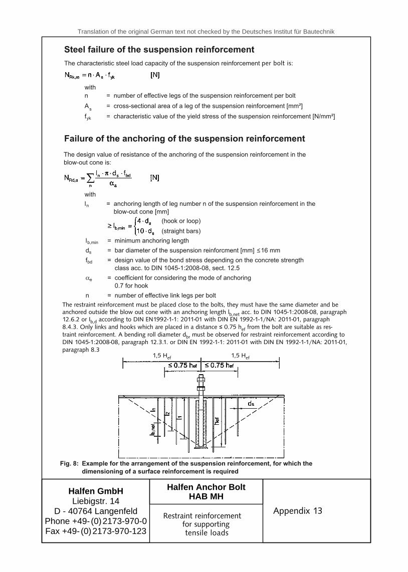
Steel failure of the suspension reinforcement
The characteristic steel load capacity of the suspension reinforcement is per bolt:
Failure of the anchoring of the suspension reinforcement
l = anchoring length of leg number n of the suspension reinforcement in theblow-out cone [mm]
n
(hook or loop)
(straight bars)
The design value of resistance of the anchoring of the suspension reinforcement in theblow-out cone is:
Fig. 8: Example for the arrangement of the suspension reinforcement, for which the
dimensioning of a surface reinforcement is required
The suspension reinforcement should be placed immediately near the bolt.The legs of the links should have the same diameter, and they must be anchored exterior of the blow-out cone with an anchoring length of l acc. to DIN 1045-1:2008-08, Sect. 12.6.2.
As suspension reinforcement can only be assumed links and loops, which are placed in a distance0.75 h from the bolt. For the suspension reinforcement the bending roll diameter d must be
observed according to DIN 1045-1:2008-08, Sect. 12.3.1.
b,net
ef br≤
l =b,min minimum anchoring length
d = bar diameter of the suspension reinforcment [mm] 16 mm
f = design value of the bond stress depending on the concrete strengthclass acc. to DIN 1045-1:2008-08, sect. 12.5
= coefficient for considering the mode of anchoring0.7 for hook
n = number of effective link legs per bolt
s
bd
e
≤
�
with
withn = number of effective legs of the suspension reinforcement per bolt
A = cross-sectional area of a leg of the suspension reinforcement [mm²]
characteristic value of the yield stress of the suspension reinforcement [N/mm²]s
f =yk
Appendix 13
Restraint reinforcementfor supporting tensional loads
Appendix 13
per bolt is:
tensile loads
The restraint reinforcement must be placed close to the bolts, they must have the same diameter and be anchored outside the blow out cone with an anchoring length lb,net acc. to DIN 1045-1:2008-08, paragraph 12.6.2 or Ib,d according to DIN EN1992-1-1: 2011-01 with DIN EN 1992-1-1/NA: 2011-01, paragraph 8.4.3. Only links and hooks which are placed in a distance ≤ 0.75 hef from the bolt are suitable as res-traint reinforcement. A bending roll diameter dbr must be observed for restraint reinforcement according to DIN 1045-1:2008-08, paragraph 12.3.1. or DIN EN 1992-1-1: 2011-01 with DIN EN 1992-1-1/NA: 2011-01, paragraph 8.3
1,5 Hef 1,5 Hef

Translation of the original German text not checked by the Deutsches Institut für Bautechnik
Halfen GmbHLiebigstr. 14
D - 40764 LangenfeldPhone +49- (0) 2173-970-0Fax +49- (0) 2173-970-123
to GeneralCertificate of ApprovalZ-21.5 - 1758dated October 28, 2008
Halfen Anchor BoltHAB MH
Characteristic resistance values for the proof of theload capacity under transverse stress
Anchor Bolt size
Charcteristic resistanceVRk,s [kN] under transverseload without lever arm
Charcteristic resistanceM [Nm] under0
Rk,s transverseload with lever arm
Table 6: Characteristic resistance values of an Anchor Bolt undertransverse load with and without lever arm at steel failure
The following applies for transverse load with lever arm:
Fig. 9: Transverse load with lever arm, definitions
(lever arm, d acc. to Appendix 4)3
Distance between transverse load and concrete surface
Appendix 14
Characteristic transverseload-bearing capacity in the
case of steel failure
Appendix 14
Characteristic resistance
Characteristic resistance
appendix

Translation of the original German text not checked by the Deutsches Institut für Bautechnik
Halfen GmbHLiebigstr. 14
D - 40764 LangenfeldPhone +49- (0) 2173-970-0Fax +49- (0) 2173-970-123
to GeneralCertificate of ApprovalZ-21.5 - 1758dated October 28, 2008
Halfen Anchor BoltHAB MH
Concrete failure - concrete blow-out on the side facing away from the load
The associated characteristic transverse load capacity V is to be calculated fromEquation 3.9:
Rk,cp
is to be calculated according to Equation 3.8 (Appendix 10). Thereby NRk,c
is to be determined for the Anchor Bolts under transverse stress.
For anchor connections with suspension reinforcement acc. to Appendix 20or 19 this factor is to be assessed with 1.5 .
Fig. 10: Concrete blow-out on the side facing away from the load
Idealised blow-outsurface
Appendix 15
Characteristic transverseload-bearing capacity for
concrete blow-out on the sidefacing away from the load
Appendix 15
equation
equation appendix
appendix
Translation of the original German text not checked by the Deutsches Institut für Bautechnik
Halfen GmbHLiebigstr. 14
D - 40764 LangenfeldPhone +49- (0) 2173-970-0Fax +49- (0) 2173-970-123
to GeneralCertificate of ApprovalZ-21.5 - 1758dated October 28, 2008
Halfen Anchor BoltHAB MH
Concrete edge blow-out at anchor connections near the edge
The characteristic transverse load capacity of an Anchor Bolt or an Anchor Bolt groupsituated near the edge is as follows:
For the calculation of the characteristic transverse load capacity of Anchor Bolt groups onlythe most unfavorably positioned Anchor Bolt or the Anchor Bolt with the most unfavorableposition at the edge of the structural element must be used (see Appendix 17, Fig. 12)
In the following the individual factors of the Equation (3.10) are specified.
The initial value of the characteristic transverse load capacity of an Anchor Bolt with loadin perpendicular direction relative to the edge of the structural element is:
[N] with
may be assessed with at most 60 N/mm²
For Anchor Bolts in the sizes HAB MH45, HAB MH52 and HAB MH60 the value is to bemultiplied by the factor 0.8.
The influence of the centre spacings and further edge distances parallel to the loaddirection and of the thickness of the structural element on the characteristic load capacityis considered through the ratio A /A :c,v c,v
0
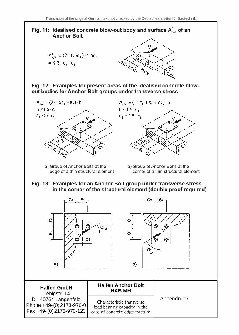
Surface of the blow-out body of an Anchor Bolt on the lateral concrete surfacewithout influence of edges parallel to the assumed load direction, of thicknessof structural element or of adjacent Anchor Bolts. Thereby the blow-out bodyis assumed as a half pyramide with the height c and the length of the basesides 1.5 c and 3 c (see Appendix 17, Fig. 11).
Present area of the blow-out body of the anchor connection on the lateral sideof the concrete. It is limited by the overlappings of the individual blow-outbodies of adjacent anchor connections (s 3 c ) and by the edges of thestructural elements parallel to the assumed load direction
1
1
1
1
≤
(c 1.5 c ) and thethickness of the structural element (h 1.5 c ).Examples for the calculation of A : see Appendix 17, Fig. 12).
2 1
1
c,V
≤
≤
For the calculation of A t is assumed, that the transverse load is appliedperpendicularly to the edge of the structural element.
For anchor connections in the corner of the structural element (c
c,v
2
0c,v
1
and A i
1.5 c ) the proof mustbe carried out for both edges of the structural elements (see Appendix 17, Fig. 13).
≤
Appendix 16
Characteristic transverseload-bearing capacity in the
case of concrete edge fracture
Appendix 16
may be used (see appendix 17, fig. 12)
(see figure 11).
(see figure 12).
at max. 60 N/mm²
pyramid
( see appendix 17, fig. 13)
max. 60 N/mm²
,
Translation of the original German text not checked by the Deutsches Institut für Bautechnik
Halfen GmbHLiebigstr. 14
D - 40764 LangenfeldPhone +49- (0) 2173-970-0Fax +49- (0) 2173-970-123
to GeneralCertificate of ApprovalZ-21.5 - 1758dated October 28, 2008
Halfen Anchor BoltHAB MH
Fig. 11: Idealised concrete blow-out body and surface A of anAnchor Bolt
0c,v
Fig. 12: Examples for present areas of the idealised concrete blow-out bodies for Anchor Bolt groups under transverse stress
Fig. 13: Examples for an Anchor Bolt group under transverse stressin the corner of the structural element (double proof required)
a) Group of Anchor Bolts at theedge of a thin structural element
a) Group of Anchor Bolts at thecorner of a thin structural element
Appendix 17
Characteristic transverseload-bearing capacity in the
case of concrete edge fracture
Appendix 17

Translation of the original German text not checked by the Deutsches Institut für Bautechnik
Halfen GmbHLiebigstr. 14
D - 40764 LangenfeldPhone +49- (0) 2173-970-0Fax +49- (0) 2173-970-123
to GeneralCertificate of ApprovalZ-21.5 - 1758dated October 28, 2008
Halfen Anchor BoltHAB MH
The factor of influence �s,V takes into account the disruption of the state of stress in theconcrete by further edges of the structural element. At anchor connections with two edgedistances parallel to the load direction (e.g. in a slim structural element) the smaller edgedistance has to be used in the Equation (3.10b).
The factor �h,V takes into account, that the transverse load capacity does not decreaseproportionally with the thickness of the structural element.
With the factor � ��,V the angle between the impinging load V and the directionperpendicular to the free edge of the structural element is considered (see Fig. 14).
The factor of influence �ec,V takes into account the non-centric transverse stress of agroup of Anchor Bolts.
Non-centricity of the resulting transverse load of the Anchor Bolts. The non-centricity is to be determined from the calculated forces of the Anchor Bolts. Ithas to be related to the geometrical centre of mass G of the transverse-stressedAnchor Bolts.
To be on the safe side, the factor of influence may be set to = 1.0, when thecharacteristic load capacity of the Anchor Bolt with the highest load is calculated with
�ec,V
n = number of transverse-stressed Anchor Bolts
Then, instead of the proof acc. to Table 3.3, Line 4a, the proof
must be carried out.
Ed
ge
of
the
stru
ctu
ral e
lem
en
t
Characteristic transverseload-bearing capacity in the
case of concrete edge fracture
Appendix 18
Appendix 18
equation
acting load V and the directionfig.
table 3.3, line 4a, the proof
Fig. 14 Defi nition of the angle αv

Translation of the original German text not checked by the Deutsches Institut für Bautechnik
Halfen GmbHLiebigstr. 14
D - 40764 LangenfeldPhone +49- (0) 2173-970-0Fax +49- (0) 2173-970-123
to GeneralCertificate of ApprovalZ-21.5 - 1758dated October 28, 2008
Halfen Anchor BoltHAB MH
Only hoops and loops which lie directly against the Anchor Bolts may be used as suspen-sion reinforcement. The minimum values required according to DIN 1045-1 for the concretecover and the anchoring length must be maintained. Only the minimum bending roll dia-meter d according tobr DIN 1045-1 may be used.
Table 7: Characteristic load capacity V of one leg of the suspensionreinforcement at anchor connections near the edge for suppor-ting the transverse load.
0Rk,re
Concrete reinforcm. steel BSt 500 S
Characteristic load bearingcapacity of one leg V [kN]0
Rk,re
Suspension reinforcement
Fig. 15: Structural design of the suspension reinforcement
Appendix 19
Characteristic load-bearingcapacity of restraint reinforce-ment for transverse loading of
anchor connection near the edge
Appendix 19
Structual design of the restraint reinforcement
Restraint reinforcement
Only rings and stirrups in close contact with the Anchor Bolts may be used as restraint rein-forcement. The minimal values required according to DIN 1045-1 for the concrete cover and the anchoring length must be maintained. Only the minimum bending roll diameter dbr accor-ding to DIN 1045-1 may be used.
Translation of the original German text not checked by the Deutsches Institut für Bautechnik
Halfen GmbHLiebigstr. 14
D - 40764 LangenfeldPhone +49- (0) 2173-970-0Fax +49- (0) 2173-970-123
to GeneralCertificate of ApprovalZ-21.5 - 1758dated October 28, 2008
Halfen Anchor BoltHAB MH
Fig. 16: Examplesof a suspension reinforcement for supporting thetransverse load with anchor connections near to the edge
Edge of struc-tural element
Suspension reinforcement
Bolt
Anchoring length acc. to DIN 1045-1
Edge of struc-tural element
Suspension reinforcement
Anchoring length acc. to DIN 1045-1
Appendix 20
Examples of a restraintreinforcement for supporting
the transverse load with anchorconnections near to the edge
Appendix 20
Restraint reinforcement
Examples of restraint reinforcement for supporting the transverse load with close to the edge anchor connections
Restraint reinforcement

© 2
012
HA
LFEN
Gm
bH, G
erm
any
appl
ies
also
to
copy
ing
in e
xtra
cts.
RE
- 072
- E
- 09/
12
09/
12
The Quality Management System of Halfen GmbH is certified for the locations in Germany, France, Austria, Poland, Switzerland
and the Czech Republic according to DIN EN ISO 9001:2008, Certificate No. QS-281 HH.
Furthermore HALFEN is represented with sales offices and distributors worldwide. Please contact us: www.halfen.com
Austria HALFEN Gesellschaft m.b.H.Leonard-Bernstein-Str. 101220 Wien
Phone: +43 - 1 - 259 6770 E-Mail: [email protected]: www.halfen.at
Fax: +43 - 1 - 259 - 6770 99
Belgium/Luxembourg HALFEN N.V.Borkelstraat 1312900 Schoten
Phone: +32 - 3 - 658 07 20E-Mail: [email protected]: www.halfen.be
Fax: +32 - 3 - 658 15 33
China HALFEN Construction Accessories Distribution Co.Ltd.Room 601 Tower D, Vantone CentreNo.A6 Chao Yang Men Wai StreetChaoyang District Beijing · P.R. China 100020
Phone: +86 - 10 5907 3200E-Mail: [email protected]: www.halfen.cn
Fax: +86 - 10 5907 3218
Czech Republic HALFEN-DEHA s.r.o.Business Center ŠafránkovaŠafránkova 1238/1155 00 Praha 5
Phone: +420 - 311 - 690 060E-Mail: [email protected]: www.halfen-deha.cz
Fax: +420 - 235 - 314 308
France HALFEN S.A.S.18, rue Goubet75019 Paris
Phone: +33 - 1 - 445231 00E-Mail: [email protected]: www.halfen.fr
Fax: +33 - 1 - 445231 52
Germany HALFEN Vertriebsgesellschaft mbHKatzbergstrasse 3 40764 Langenfeld
Phone: +49 - 2173 - 970 0E-Mail: [email protected]: www.halfen.de
Fax: +49 - 2173 - 970 225
Italy HALFEN S.r.l. Soc. UnipersonaleVia F.lli Bronzetti N° 2824124 Bergamo
Phone: +39 - 035 - 0760711E-Mail: [email protected]: www.halfen.it
Fax: +39 - 035 - 0760799
Netherlands HALFEN b.v.Oostermaat 37623 CS Borne
Phone: +31 - 742 - 6714 49E-Mail: [email protected]: www.halfen.nl
Fax: +31 - 742 6726 59
Norway HALFEN ASPostboks 20804095 Stavanger
Phone: +47 - 51 82 34 00E-Mail: [email protected]: www.halfen.no
Fax: +47 - 51 82 34 01
Poland HALFEN Sp. z o.o.Ul. Obornicka 28760-691 Poznan
Phone: +48 - 61 - 622 14 14E-Mail: [email protected]: www.halfen.pl
Fax: +48 - 61 - 622 14 15
Spain HALFEN S.L.c/ Fuente de la Mora 2, 2° D28050 Madrid
Phone: +34 - 91 - 632 18 40E-Mail: [email protected]: www.halfen.es
Fax: +34 - 91 - 633 42 57
Sweden Halfen ABBox 150435 23 Mölnlycke
Phone: +46 - 31 - 98 58 00E-Mail: [email protected]: www.halfen.se
Fax: +46 - 31 - 98 58 01
Switzerland HALFEN Swiss AGHertistrasse 25 8304 Wallisellen
Phone: +41 - 44 - 849 78 78E-Mail: [email protected]: www.halfen.ch
Fax: +41 - 44 - 849 78 79
United Kingdom /Ireland
HALFEN Ltd.Humphrys Road · Woodside EstateDunstable LU5 4TP
Phone: +44 - 1582 - 47 03 00E-Mail: [email protected]: www.halfen.co.uk
Fax: +44 - 1582 - 47 03 04
United States of America
HALFEN USA Inc.8521 FM 1976P.O. Box 547Converse, TX 78109
Phone: +1 800.423.91 40E-Mail: [email protected]: www.halfenusa.com
Fax: +1 888 . 227.16 95
CONTACT HALFEN WORLDWIDE
HALFEN is represented by subs id iar ies in the fo l lowing 15 countr ies , p lease contact us :