
Halderman ch030 lecture
130
© 2011 Pearson Education, In All Rights Reserv Automotive Technology, Fourth Edition James Halderman CYLINDER HEAD AND VALVE GUIDE SERVICE 30
Transcript of Halderman ch030 lecture
© 2011 Pearson Education, Inc.All Rights Reserved
Automotive Technology, Fourth EditionJames Halderman
CYLINDER HEAD AND VALVE GUIDE SERVICE
30

30 CYLINDER HEAD AND VALVE GUIDE SERVICE
Automotive Technology, Fourth EditionJames Halderman
© 2011 Pearson Education, Inc.All Rights Reserved
ObjectivesObjectives
• The student should be able to:– Prepare for ASE Engine Repair (A1)
certification test content area “B” (Cylinder Head and Valve Train Diagnosis and Repair).
– Identify combustion chamber types.

30 CYLINDER HEAD AND VALVE GUIDE SERVICE
Automotive Technology, Fourth EditionJames Halderman
© 2011 Pearson Education, Inc.All Rights Reserved
ObjectivesObjectives
• The student should be able to:– List the steps necessary to recondition a
cylinder head. – Describe how to inspect and measure valve
guides. – Discuss valve guide repair options.
30 CYLINDER HEAD AND VALVE GUIDE SERVICE
Automotive Technology, Fourth EditionJames Halderman
© 2011 Pearson Education, Inc.All Rights Reserved
INTRODUCTIONINTRODUCTION

30 CYLINDER HEAD AND VALVE GUIDE SERVICE
Automotive Technology, Fourth EditionJames Halderman
© 2011 Pearson Education, Inc.All Rights Reserved
IntroductionIntroduction
• Repair of cylinder heads is the most frequent engine repair
• Highest temperatures and pressures in the engine are in the combustion chamber of the cylinder head
• Valves open and close thousands of times during engine operation
30 CYLINDER HEAD AND VALVE GUIDE SERVICE
Automotive Technology, Fourth EditionJames Halderman
© 2011 Pearson Education, Inc.All Rights Reserved
CYLINDER HEADSCYLINDER HEADS

30 CYLINDER HEAD AND VALVE GUIDE SERVICE
Automotive Technology, Fourth EditionJames Halderman
© 2011 Pearson Education, Inc.All Rights Reserved
Cylinder HeadsCylinder Heads
• Construction– Supports the valves and valve train– Handles flow of intake, exhaust gases,
coolant, and sometimes oil
30 CYLINDER HEAD AND VALVE GUIDE SERVICE
Automotive Technology, Fourth EditionJames Halderman
© 2011 Pearson Education, Inc.All Rights Reserved
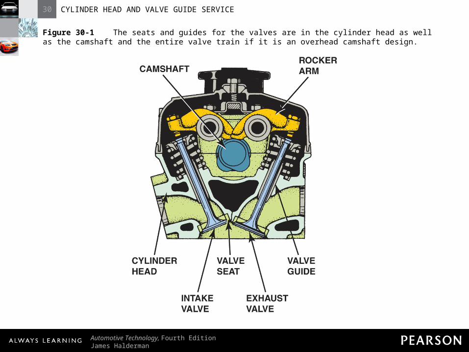
Figure 30-1 The seats and guides for the valves are in the cylinder head as well as the camshaft and the entire valve train if it is an overhead camshaft design.
30 CYLINDER HEAD AND VALVE GUIDE SERVICE
Automotive Technology, Fourth EditionJames Halderman
© 2011 Pearson Education, Inc.All Rights Reserved
Cylinder HeadsCylinder Heads
• Design Features– Squish area– Quench area– Spark plug placement

30 CYLINDER HEAD AND VALVE GUIDE SERVICE
Automotive Technology, Fourth EditionJames Halderman
© 2011 Pearson Education, Inc.All Rights Reserved
Cylinder HeadsCylinder Heads
• Design Features– Surface-to-volume ratio– Valve shrouding– Crossflow valve placement

30 CYLINDER HEAD AND VALVE GUIDE SERVICE
Automotive Technology, Fourth EditionJames Halderman
© 2011 Pearson Education, Inc.All Rights Reserved
Figure 30-2 A wedge-shaped combustion chamber showing the squish area where the air-fuel mixture is squeezed, causing turbulence that pushes the mixture toward the spark plug.

30 CYLINDER HEAD AND VALVE GUIDE SERVICE
Automotive Technology, Fourth EditionJames Halderman
© 2011 Pearson Education, Inc.All Rights Reserved
Figure 30-3 Locating the spark plug in the center of the combustion chamber reduces the distance the flame front must travel.

30 CYLINDER HEAD AND VALVE GUIDE SERVICE
Automotive Technology, Fourth EditionJames Halderman
© 2011 Pearson Education, Inc.All Rights Reserved
Figure 30-4 The combustion chamber of the 5.7 liter Chrysler Hemi cylinder head shows the two spark plugs used to ensure rapid burn for best power and economy with the lowest possible exhaust emissions.

30 CYLINDER HEAD AND VALVE GUIDE SERVICE
Automotive Technology, Fourth EditionJames Halderman
© 2011 Pearson Education, Inc.All Rights Reserved
Figure 30-5 The shrouded area around the intake valve causes the intake mixture to swirl as it enters the combustion chamber.

30 CYLINDER HEAD AND VALVE GUIDE SERVICE
Automotive Technology, Fourth EditionJames Halderman
© 2011 Pearson Education, Inc.All Rights Reserved
Figure 30-6 A typical cross flow cylinder head design, where the flow into and out of the combustion chamber is from opposite sides of the cylinder head.

30 CYLINDER HEAD AND VALVE GUIDE SERVICE
Automotive Technology, Fourth EditionJames Halderman
© 2011 Pearson Education, Inc.All Rights Reserved
Cylinder Heads Cylinder Heads
• Combustion Chamber Designs– Created as two parts– Upper part: cylinder head and walls– Lower part: top of the piston

30 CYLINDER HEAD AND VALVE GUIDE SERVICE
Automotive Technology, Fourth EditionJames Halderman
© 2011 Pearson Education, Inc.All Rights Reserved
Cylinder Heads Cylinder Heads
• Combustion Chamber Designs– Most common shapes include:
• Wedge• Pentroof• Hemi
?
30 CYLINDER HEAD AND VALVE GUIDE SERVICE
Automotive Technology, Fourth EditionJames Halderman
© 2011 Pearson Education, Inc.All Rights Reserved
Cylinder Heads Cylinder Heads
• Four-Valve Cylinder Heads– More than two valves allow more gas to
flow through the engine– Valve duration: number of degrees by
which the crankshaft rotates when the valve is off the valve seat

30 CYLINDER HEAD AND VALVE GUIDE SERVICE
Automotive Technology, Fourth EditionJames Halderman
© 2011 Pearson Education, Inc.All Rights Reserved
Cylinder Heads Cylinder Heads
• Four-Valve Cylinder Heads– Maximum amount of gas moving through
the opening of a valve depends on the distance around the valve and the degree to which it lifts open
30 CYLINDER HEAD AND VALVE GUIDE SERVICE
Automotive Technology, Fourth EditionJames Halderman
© 2011 Pearson Education, Inc.All Rights Reserved
Cylinder Heads Cylinder Heads
• Four-Valve Cylinder Heads– The distance around a valve is calculated
by the equation:• pi × D or 3.1416 × valve diameter

30 CYLINDER HEAD AND VALVE GUIDE SERVICE
Automotive Technology, Fourth EditionJames Halderman
© 2011 Pearson Education, Inc.All Rights Reserved
Cylinder Heads Cylinder Heads
• Four-Valve Cylinder Heads– Four valves on the pentroof design are
operated with dual overhead camshafts or with single overhead camshafts and rocker arms

30 CYLINDER HEAD AND VALVE GUIDE SERVICE
Automotive Technology, Fourth EditionJames Halderman
© 2011 Pearson Education, Inc.All Rights Reserved
Cylinder Heads Cylinder Heads
• Four-Valve Cylinder Heads– Four valves make it is possible to place the
sparkplug at the center of the combustion chamber

30 CYLINDER HEAD AND VALVE GUIDE SERVICE
Automotive Technology, Fourth EditionJames Halderman
© 2011 Pearson Education, Inc.All Rights Reserved
Figure 30-7 Method for measuring the valve opening space.

30 CYLINDER HEAD AND VALVE GUIDE SERVICE
Automotive Technology, Fourth EditionJames Halderman
© 2011 Pearson Education, Inc.All Rights Reserved
Figure 30-8 Comparing the valve opening areas between a twoand three-valve combustion chamber when the valves are open.
30 CYLINDER HEAD AND VALVE GUIDE SERVICE
Automotive Technology, Fourth EditionJames Halderman
© 2011 Pearson Education, Inc.All Rights Reserved
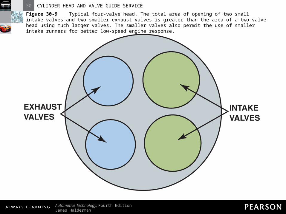
Figure 30-9 Typical four-valve head. The total area of opening of two small intake valves and two smaller exhaust valves is greater than the area of a two-valve head using much larger valves. The smaller valves also permit the use of smaller intake runners for better low-speed engine response.

30 CYLINDER HEAD AND VALVE GUIDE SERVICE
Automotive Technology, Fourth EditionJames Halderman
© 2011 Pearson Education, Inc.All Rights Reserved
Figure 30-10 Four valves in a pentroof combustion chamber.

30 CYLINDER HEAD AND VALVE GUIDE SERVICE
Automotive Technology, Fourth EditionJames Halderman
© 2011 Pearson Education, Inc.All Rights Reserved
Figure 30-11 An Audi five-valve cylinder head, which uses three intake valves and two exhaust valves.

30 CYLINDER HEAD AND VALVE GUIDE SERVICE
Automotive Technology, Fourth EditionJames Halderman
© 2011 Pearson Education, Inc.All Rights Reserved
INTAKE INTAKE AND EXHAUST PORTSAND EXHAUST PORTS

30 CYLINDER HEAD AND VALVE GUIDE SERVICE
Automotive Technology, Fourth EditionJames Halderman
© 2011 Pearson Education, Inc.All Rights Reserved
Intake and Exhaust PortsIntake and Exhaust Ports
• Purpose and Function– Port: part of the intake or exhaust system
passage cast in the cylinder head
30 CYLINDER HEAD AND VALVE GUIDE SERVICE
Automotive Technology, Fourth EditionJames Halderman
© 2011 Pearson Education, Inc.All Rights Reserved
Intake and Exhaust PortsIntake and Exhaust Ports
• Purpose and Function– Ports lead from the manifolds to the valves

30 CYLINDER HEAD AND VALVE GUIDE SERVICE
Automotive Technology, Fourth EditionJames Halderman
© 2011 Pearson Education, Inc.All Rights Reserved
Intake and Exhaust PortsIntake and Exhaust Ports
• Purpose and Function– Inline engines may have both on the same
side of the engine– Cylinders on older engines could share a
port due to restricted space called Siamese ports

30 CYLINDER HEAD AND VALVE GUIDE SERVICE
Automotive Technology, Fourth EditionJames Halderman
© 2011 Pearson Education, Inc.All Rights Reserved
Intake and Exhaust Ports Intake and Exhaust Ports
• Intake Ports– Larger ports and better breathing are
possible in engines when the intake and exhaust ports are on opposite sides

30 CYLINDER HEAD AND VALVE GUIDE SERVICE
Automotive Technology, Fourth EditionJames Halderman
© 2011 Pearson Education, Inc.All Rights Reserved
Intake and Exhaust Ports Intake and Exhaust Ports
• Intake Ports– A restricting hump within a port could
increase its airflow capacity

30 CYLINDER HEAD AND VALVE GUIDE SERVICE
Automotive Technology, Fourth EditionJames Halderman
© 2011 Pearson Education, Inc.All Rights Reserved
Intake and Exhaust Ports Intake and Exhaust Ports
• Intake Ports– Modifications in the field, such as porting or
relieving, restrict the flow of a carefully designed port
30 CYLINDER HEAD AND VALVE GUIDE SERVICE
Automotive Technology, Fourth EditionJames Halderman
© 2011 Pearson Education, Inc.All Rights Reserved
Intake and Exhaust Ports Intake and Exhaust Ports
• Intake Ports– Intake manifold and combustion chamber
design work together to cause the air-fuel mixture to swirl in the combustion chamber

30 CYLINDER HEAD AND VALVE GUIDE SERVICE
Automotive Technology, Fourth EditionJames Halderman
© 2011 Pearson Education, Inc.All Rights Reserved
Figure 30-12 The intake manifold design and combustion chamber design both work together to cause the air-fuel mixture to swirl as it enters the combustion chamber.

30 CYLINDER HEAD AND VALVE GUIDE SERVICE
Automotive Technology, Fourth EditionJames Halderman
© 2011 Pearson Education, Inc.All Rights Reserved
Intake and Exhaust PortsIntake and Exhaust Ports
• Exhaust Ports– Designed to allow free flow of exhaust
gases from the engine– Shorter than the intake ports to help
reduce the amount of heat transferred to the coolant

30 CYLINDER HEAD AND VALVE GUIDE SERVICE
Automotive Technology, Fourth EditionJames Halderman
© 2011 Pearson Education, Inc.All Rights Reserved
Figure 30-13 A port-injected engine showing the straight free-flowing intake and exhaust ports.

30 CYLINDER HEAD AND VALVE GUIDE SERVICE
Automotive Technology, Fourth EditionJames Halderman
© 2011 Pearson Education, Inc.All Rights Reserved
CYLINDER HEAD CYLINDER HEAD PASSAGESPASSAGES

30 CYLINDER HEAD AND VALVE GUIDE SERVICE
Automotive Technology, Fourth EditionJames Halderman
© 2011 Pearson Education, Inc.All Rights Reserved
Cylinder Head PassagesCylinder Head Passages
• Coolant Flow Passages– From the coolest to the warmest portions of
the engine – Water pump takes the coolant from the
radiator

30 CYLINDER HEAD AND VALVE GUIDE SERVICE
Automotive Technology, Fourth EditionJames Halderman
© 2011 Pearson Education, Inc.All Rights Reserved
Cylinder Head PassagesCylinder Head Passages
• Coolant Flow Passages– Circulated through the block and directed
around the cylinders– Flows upward through the gasket to the
cooling passages in the cylinder head

30 CYLINDER HEAD AND VALVE GUIDE SERVICE
Automotive Technology, Fourth EditionJames Halderman
© 2011 Pearson Education, Inc.All Rights Reserved
Cylinder Head PassagesCylinder Head Passages
• Coolant Flow Passages– Heated coolant is collected and returned to
the radiator to be cooled and recycled

30 CYLINDER HEAD AND VALVE GUIDE SERVICE
Automotive Technology, Fourth EditionJames Halderman
© 2011 Pearson Education, Inc.All Rights Reserved
Cylinder Head PassagesCylinder Head Passages
• NOTE: Reversed-flow cooling systems, such as that used on the Chevrolet LT1 V-8, send the coolant from the radiator to the cylinder heads first. This results in a cooler cylinder head and allows for more spark advance without engine-damaging detonation.

30 CYLINDER HEAD AND VALVE GUIDE SERVICE
Automotive Technology, Fourth EditionJames Halderman
© 2011 Pearson Education, Inc.All Rights Reserved
Figure 30-14 A cutaway head showing the coolant passages in green.
30 CYLINDER HEAD AND VALVE GUIDE SERVICE
Automotive Technology, Fourth EditionJames Halderman
© 2011 Pearson Education, Inc.All Rights Reserved
Cylinder Head PassagesCylinder Head Passages
• Head Gasket Holes– Gasket surface of head leading to cooling
passages has large holes
30 CYLINDER HEAD AND VALVE GUIDE SERVICE
Automotive Technology, Fourth EditionJames Halderman
© 2011 Pearson Education, Inc.All Rights Reserved
Cylinder Head PassagesCylinder Head Passages
• Head Gasket Holes– Head gasket performs an important coolant
flow function when openings are too large

30 CYLINDER HEAD AND VALVE GUIDE SERVICE
Automotive Technology, Fourth EditionJames Halderman
© 2011 Pearson Education, Inc.All Rights Reserved
Cylinder Head PassagesCylinder Head Passages
• Head Gasket Holes– Special-size and smaller holes correct the
coolant flow rate at each opening

30 CYLINDER HEAD AND VALVE GUIDE SERVICE
Automotive Technology, Fourth EditionJames Halderman
© 2011 Pearson Education, Inc.All Rights Reserved
Cylinder Head PassagesCylinder Head Passages
• Head Gasket Holes– Correct head gasket installation is
necessary for proper engine cooling

30 CYLINDER HEAD AND VALVE GUIDE SERVICE
Automotive Technology, Fourth EditionJames Halderman
© 2011 Pearson Education, Inc.All Rights Reserved
Figure 30-15 Coolant flows through the cylinder head, and the passages are sealed by the head gasket.
30 CYLINDER HEAD AND VALVE GUIDE SERVICE
Automotive Technology, Fourth EditionJames Halderman
© 2011 Pearson Education, Inc.All Rights Reserved
Cylinder Head PassagesCylinder Head Passages
• Lubricating Oil Passages– Lubricating oil is delivered to overhead
valve mechanism– Special openings in head gasket allow oil to
pass between the block and head without leaking

30 CYLINDER HEAD AND VALVE GUIDE SERVICE
Automotive Technology, Fourth EditionJames Halderman
© 2011 Pearson Education, Inc.All Rights Reserved
Cylinder Head PassagesCylinder Head Passages
• Lubricating Oil Passages– Oil returns to the oil pan through oil return
passages

30 CYLINDER HEAD AND VALVE GUIDE SERVICE
Automotive Technology, Fourth EditionJames Halderman
© 2011 Pearson Education, Inc.All Rights Reserved
Cylinder Head PassagesCylinder Head Passages
• NOTE: Many aluminum cylinder heads have smaller-than-normal drainback holes. If an engine has excessive oil consumption, check the drain holes before removing the engine.

30 CYLINDER HEAD AND VALVE GUIDE SERVICE
Automotive Technology, Fourth EditionJames Halderman
© 2011 Pearson Education, Inc.All Rights Reserved
CYLINDER HEAD CYLINDER HEAD SERVICINGSERVICING

30 CYLINDER HEAD AND VALVE GUIDE SERVICE
Automotive Technology, Fourth EditionJames Halderman
© 2011 Pearson Education, Inc.All Rights Reserved
Cylinder Head ServicingCylinder Head Servicing
• Cylinder Head Servicing Sequence– Disassemble and thoroughly clean the
heads– Check for cracks and repair as necessary
30 CYLINDER HEAD AND VALVE GUIDE SERVICE
Automotive Technology, Fourth EditionJames Halderman
© 2011 Pearson Education, Inc.All Rights Reserved
Cylinder Head ServicingCylinder Head Servicing
• Cylinder Head Servicing Sequence– Check the surface that contacts the engine
block and machine, if necessary

30 CYLINDER HEAD AND VALVE GUIDE SERVICE
Automotive Technology, Fourth EditionJames Halderman
© 2011 Pearson Education, Inc.All Rights Reserved
Cylinder Head ServicingCylinder Head Servicing
• Cylinder Head Servicing Sequence– Check valve guides and replace or service,
as necessary– Grind valves and reinstall them in the
cylinder head with new valve stem seals

30 CYLINDER HEAD AND VALVE GUIDE SERVICE
Automotive Technology, Fourth EditionJames Halderman
© 2011 Pearson Education, Inc.All Rights Reserved
Cylinder Head ServicingCylinder Head Servicing
• Disassembling Overhead Camshaft Head– When one-piece bearings are used, the
valve springs have to be compressed with a fixture or the finger follower has to be removed
30 CYLINDER HEAD AND VALVE GUIDE SERVICE
Automotive Technology, Fourth EditionJames Halderman
© 2011 Pearson Education, Inc.All Rights Reserved
Cylinder Head ServicingCylinder Head Servicing
• Disassembling Overhead Camshaft Head– When bearing caps are used, loosen valve
springs alternately so that bending loads are not placed on either the cam or bearing caps

30 CYLINDER HEAD AND VALVE GUIDE SERVICE
Automotive Technology, Fourth EditionJames Halderman
© 2011 Pearson Education, Inc.All Rights Reserved
Figure 30-16 Overhead camshafts may be (a) held in place with bearing caps, (b) supported by towers, or (c) fitted into bearing bores machined directly into the head.

30 CYLINDER HEAD AND VALVE GUIDE SERVICE
Automotive Technology, Fourth EditionJames Halderman
© 2011 Pearson Education, Inc.All Rights Reserved
Figure 30-17 Always follow the specified loosening sequence to prevent valve spring tension from bending the camshaft.

30 CYLINDER HEAD AND VALVE GUIDE SERVICE
Automotive Technology, Fourth EditionJames Halderman
© 2011 Pearson Education, Inc.All Rights Reserved
Cylinder Head ServicingCylinder Head Servicing
• Valve Train Disassembly– Disassemble cylinder head– Keep the top part of the pushrod at the top

30 CYLINDER HEAD AND VALVE GUIDE SERVICE
Automotive Technology, Fourth EditionJames Halderman
© 2011 Pearson Education, Inc.All Rights Reserved
Cylinder Head ServicingCylinder Head Servicing
• Valve Train Disassembly– Keep the rocker arms with the same
pushrods– Intake and exhaust valve springs must be
kept with the correct valve
30 CYLINDER HEAD AND VALVE GUIDE SERVICE
Automotive Technology, Fourth EditionJames Halderman
© 2011 Pearson Education, Inc.All Rights Reserved
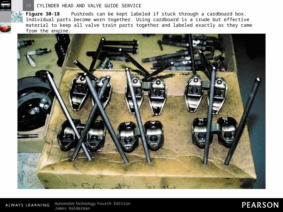
Figure 30-18 Pushrods can be kept labeled if stuck through a cardboard box. Individual parts become worn together. Using cardboard is a crude but effective material to keep all valve train parts together and labeled exactly as they came from the engine.

30 CYLINDER HEAD AND VALVE GUIDE SERVICE
Automotive Technology, Fourth EditionJames Halderman
© 2011 Pearson Education, Inc.All Rights Reserved
Cylinder Head ServicingCylinder Head Servicing
• Cylinder Head Inspection– Clean surface and inspect as follows:
• Remove old gasket material and draw a file across the surface of the head to remove any small burrs

30 CYLINDER HEAD AND VALVE GUIDE SERVICE
Automotive Technology, Fourth EditionJames Halderman
© 2011 Pearson Education, Inc.All Rights Reserved
Cylinder Head ServicingCylinder Head Servicing
• Cylinder Head Inspection– Clean surface and inspect as follows:
• Check the head in five planes for warpage, distortion, bends, and twists (slide a 0.004 in. (0.1 mm) feeler gauge under a precision straightedge held against the head surface; clearance between the two should not vary by more than 0.004 in. overall)
30 CYLINDER HEAD AND VALVE GUIDE SERVICE
Automotive Technology, Fourth EditionJames Halderman
© 2011 Pearson Education, Inc.All Rights Reserved
Cylinder Head ServicingCylinder Head Servicing
• Cylinder Head Inspection– NOTE: The cylinder head surface that
mates with the top deck of the block is often called the fire deck.

30 CYLINDER HEAD AND VALVE GUIDE SERVICE
Automotive Technology, Fourth EditionJames Halderman
© 2011 Pearson Education, Inc.All Rights Reserved
Cylinder Head ServicingCylinder Head Servicing
• Cylinder Head Inspection– NOTE: Always check the cylinder head
thickness and specifications to be sure that material can be safely removed from the surface. Some manufacturers do not recommend any machining, but rather require cylinder head replacement if cylinder head surface flatness is not within specifications.

30 CYLINDER HEAD AND VALVE GUIDE SERVICE
Automotive Technology, Fourth EditionJames Halderman
© 2011 Pearson Education, Inc.All Rights Reserved
Figure 30-19 Cylinder heads should be checked in five planes for warpage, distortion, bend, and twist.
30 CYLINDER HEAD AND VALVE GUIDE SERVICE
Automotive Technology, Fourth EditionJames Halderman
© 2011 Pearson Education, Inc.All Rights Reserved
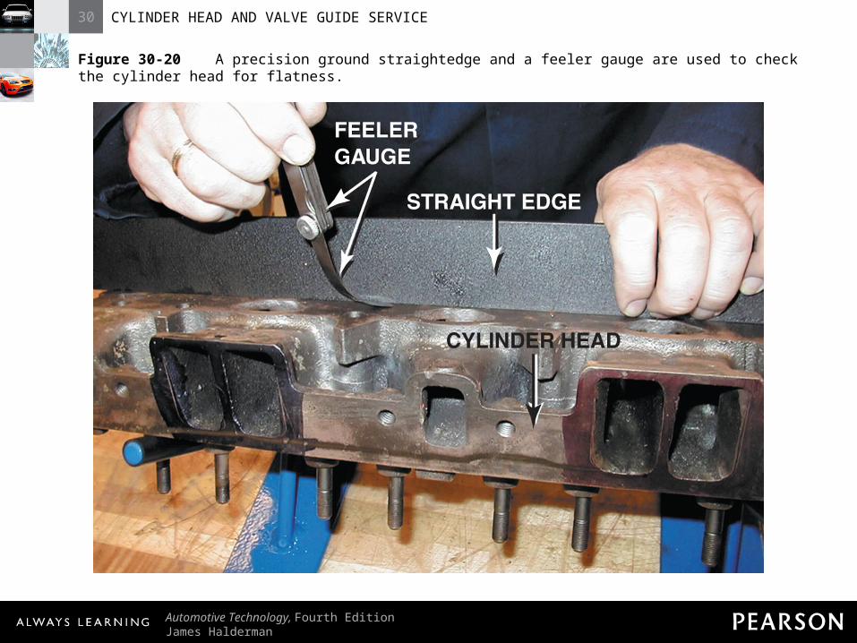
Figure 30-20 A precision ground straightedge and a feeler gauge are used to check the cylinder head for flatness.

30 CYLINDER HEAD AND VALVE GUIDE SERVICE
Automotive Technology, Fourth EditionJames Halderman
© 2011 Pearson Education, Inc.All Rights Reserved
ALUMINUM CYLINDERALUMINUM CYLINDERHEAD STRAIGHTENINGHEAD STRAIGHTENING

30 CYLINDER HEAD AND VALVE GUIDE SERVICE
Automotive Technology, Fourth EditionJames Halderman
© 2011 Pearson Education, Inc.All Rights Reserved
Aluminum Cylinder Head Aluminum Cylinder Head Straightening Straightening
• Purpose and Function– STEP 1: Determine the amount of warpage
with a straightedge and thickness (feeler) gauge. Cut shim stock (thin strips of metal) to one-half of the amount of the warpage. Place shims of this thickness under each end of the head.

30 CYLINDER HEAD AND VALVE GUIDE SERVICE
Automotive Technology, Fourth EditionJames Halderman
© 2011 Pearson Education, Inc.All Rights Reserved
Aluminum Cylinder Head Aluminum Cylinder Head Straightening Straightening
• Purpose and Function– STEP 2: Tighten the center of the cylinder
head down on a strong, flat base. A 2 in. thick piece of steel that is 8 in. wide by 20 in. long makes a good support for the gasket surface of the cylinder head (use antiseize compound on the bolt threads to help in bolt removal).

30 CYLINDER HEAD AND VALVE GUIDE SERVICE
Automotive Technology, Fourth EditionJames Halderman
© 2011 Pearson Education, Inc.All Rights Reserved
Aluminum Cylinder Head Aluminum Cylinder Head Straightening Straightening
• Purpose and Function– STEP 3: Place the head and base in an oven
for five hours at 500°F (260°C). Turn the oven off and leave the assembly in the oven.

30 CYLINDER HEAD AND VALVE GUIDE SERVICE
Automotive Technology, Fourth EditionJames Halderman
© 2011 Pearson Education, Inc.All Rights Reserved
Aluminum Cylinder Head Aluminum Cylinder Head Straightening Straightening
• Purpose and Function– NOTE: If the temperature is too high, the
valve seat inserts may fall out of the head! At 500°F, a typical valve seat will still be held into the aluminum head with a 0.002 in. interference fit based on calculations of thermal expansion of the aluminum head and steel insert.

30 CYLINDER HEAD AND VALVE GUIDE SERVICE
Automotive Technology, Fourth EditionJames Halderman
© 2011 Pearson Education, Inc.All Rights Reserved
Figure 30-21 Warped overhead camshaft cylinder head. If the gasket surface is machined to be flat, the camshaft bearings will still not be in proper alignment. The solution is to straighten the cylinder head or to align bore the cam tunnel.
30 CYLINDER HEAD AND VALVE GUIDE SERVICE
Automotive Technology, Fourth EditionJames Halderman
© 2011 Pearson Education, Inc.All Rights Reserved
Aluminum Cylinder Head Aluminum Cylinder Head StraighteningStraightening
• Purpose and Function– Cool head in oven at least four to five hours– Heating/cooling process can be repeated if
necessary

30 CYLINDER HEAD AND VALVE GUIDE SERVICE
Automotive Technology, Fourth EditionJames Halderman
© 2011 Pearson Education, Inc.All Rights Reserved
Aluminum Cylinder Head Aluminum Cylinder Head StraighteningStraightening
• Purpose and Function– Gasket surface (fire deck) can be machined
in the usual manner after straightening

30 CYLINDER HEAD AND VALVE GUIDE SERVICE
Automotive Technology, Fourth EditionJames Halderman
© 2011 Pearson Education, Inc.All Rights Reserved
CYLINDER HEADCYLINDER HEADRESURFACINGRESURFACING
30 CYLINDER HEAD AND VALVE GUIDE SERVICE
Automotive Technology, Fourth EditionJames Halderman
© 2011 Pearson Education, Inc.All Rights Reserved
Cylinder Head ResurfacingCylinder Head Resurfacing
• Refinishing Methods– Two common methods:
• Milling or broaching uses metal-cutting tool bits fastened in a disc
30 CYLINDER HEAD AND VALVE GUIDE SERVICE
Automotive Technology, Fourth EditionJames Halderman
© 2011 Pearson Education, Inc.All Rights Reserved
Cylinder Head ResurfacingCylinder Head Resurfacing
• Refinishing Methods– Two common methods:
• Grinding uses a large-diameter abrasive wheel
– Both can be done with table-type or precision-type resurfacers

30 CYLINDER HEAD AND VALVE GUIDE SERVICE
Automotive Technology, Fourth EditionJames Halderman
© 2011 Pearson Education, Inc.All Rights Reserved
Cylinder Head ResurfacingCylinder Head Resurfacing
• Refinishing Methods– NOTE: Resurfacing the cylinder head
changes the compression ratio of the engine by about 1/10 point per 0.01 in. of removed material. For example, the compression ratio would be increased from 9.0:1 to 9.2:1 if 0.02 in. were removed from a typical cylinder head.

30 CYLINDER HEAD AND VALVE GUIDE SERVICE
Automotive Technology, Fourth EditionJames Halderman
© 2011 Pearson Education, Inc.All Rights Reserved
Figure 30-22 A cast-iron cylinder head being resurfaced using a surface grinder.
30 CYLINDER HEAD AND VALVE GUIDE SERVICE
Automotive Technology, Fourth EditionJames Halderman
© 2011 Pearson Education, Inc.All Rights Reserved
Cylinder Head ResurfacingCylinder Head Resurfacing
• Surface Finish– Measured in microinches (abbreviated “μ
in.”)– Arithmetic average roughness height (RA)
is used to express surface finish

30 CYLINDER HEAD AND VALVE GUIDE SERVICE
Automotive Technology, Fourth EditionJames Halderman
© 2011 Pearson Education, Inc.All Rights Reserved
Cylinder Head ResurfacingCylinder Head Resurfacing
• Surface Finish– Root-mean-square (RMS) classification is
becoming obsolete

30 CYLINDER HEAD AND VALVE GUIDE SERVICE
Automotive Technology, Fourth EditionJames Halderman
© 2011 Pearson Education, Inc.All Rights Reserved
Cylinder Head ResurfacingCylinder Head Resurfacing
• Surface Finish– Surface finish roughness recommendations
for cylinder heads and blocks include the following:
• Cast iron– Maximum: 110 RA (125 RMS)

30 CYLINDER HEAD AND VALVE GUIDE SERVICE
Automotive Technology, Fourth EditionJames Halderman
© 2011 Pearson Education, Inc.All Rights Reserved
Cylinder Head ResurfacingCylinder Head Resurfacing
• Surface Finish– Surface finish roughness recommendations
for cylinder heads and blocks include the following:
• Cast iron– Minimum: 30 RA (33 RMS)

30 CYLINDER HEAD AND VALVE GUIDE SERVICE
Automotive Technology, Fourth EditionJames Halderman
© 2011 Pearson Education, Inc.All Rights Reserved
Cylinder Head ResurfacingCylinder Head Resurfacing
• Surface Finish– Surface finish roughness recommendations
for cylinder heads and blocks include the following:
• Cast iron– Recommended range: 60 to 100 RA (65 to
110 RMS)

30 CYLINDER HEAD AND VALVE GUIDE SERVICE
Automotive Technology, Fourth EditionJames Halderman
© 2011 Pearson Education, Inc.All Rights Reserved
Cylinder Head ResurfacingCylinder Head Resurfacing
• Surface Finish– Surface finish roughness recommendations
for cylinder heads and blocks include the following:
• Aluminum– Maximum: 60 RA (65 RMS)

30 CYLINDER HEAD AND VALVE GUIDE SERVICE
Automotive Technology, Fourth EditionJames Halderman
© 2011 Pearson Education, Inc.All Rights Reserved
Cylinder Head ResurfacingCylinder Head Resurfacing
• Surface Finish– Surface finish roughness recommendations
for cylinder heads and blocks include the following:
– Minimum: 30 RA (33 RMS)

30 CYLINDER HEAD AND VALVE GUIDE SERVICE
Automotive Technology, Fourth EditionJames Halderman
© 2011 Pearson Education, Inc.All Rights Reserved
Cylinder Head ResurfacingCylinder Head Resurfacing
• Surface Finish– Surface finish roughness recommendations
for cylinder heads and blocks include the following:
– Recommended range: 50 to 60 RA (55 to 65 RMS)
30 CYLINDER HEAD AND VALVE GUIDE SERVICE
Automotive Technology, Fourth EditionJames Halderman
© 2011 Pearson Education, Inc.All Rights Reserved
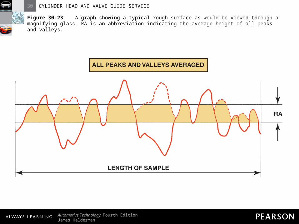
Figure 30-23 A graph showing a typical rough surface as would be viewed through a magnifying glass. RA is an abbreviation indicating the average height of all peaks and valleys.

30 CYLINDER HEAD AND VALVE GUIDE SERVICE
Automotive Technology, Fourth EditionJames Halderman
© 2011 Pearson Education, Inc.All Rights Reserved
INTAKE MANIFOLD INTAKE MANIFOLD ALIGNMENTALIGNMENT

30 CYLINDER HEAD AND VALVE GUIDE SERVICE
Automotive Technology, Fourth EditionJames Halderman
© 2011 Pearson Education, Inc.All Rights Reserved
Intake Manifold AlignmentIntake Manifold Alignment
• Purpose– Grinding gasket surfaces of the heads may
cause intake manifold to not fit correctly– Remove enough metal to rematch the ports
and bolt holes

30 CYLINDER HEAD AND VALVE GUIDE SERVICE
Automotive Technology, Fourth EditionJames Halderman
© 2011 Pearson Education, Inc.All Rights Reserved
Figure 30-24 The material that must be removed for a good manifold fit.

30 CYLINDER HEAD AND VALVE GUIDE SERVICE
Automotive Technology, Fourth EditionJames Halderman
© 2011 Pearson Education, Inc.All Rights Reserved
Intake Manifold AlignmentIntake Manifold Alignment
• Procedure– Machine shops have tables that specify the
exact amount of metal to be removed– Remove some metal from the front and
back gasket surfaces of closed-type intake manifolds

30 CYLINDER HEAD AND VALVE GUIDE SERVICE
Automotive Technology, Fourth EditionJames Halderman
© 2011 Pearson Education, Inc.All Rights Reserved
Intake Manifold AlignmentIntake Manifold Alignment
• CAUTION: Do not remove any more material than is necessary to restore a flat cylinder head-to-block surface. Some manufacturers limit total material that can be removed from the block deck and cylinder head to 0.008 in. (0.2 mm).

30 CYLINDER HEAD AND VALVE GUIDE SERVICE
Automotive Technology, Fourth EditionJames Halderman
© 2011 Pearson Education, Inc.All Rights Reserved
Intake Manifold AlignmentIntake Manifold Alignment
• CAUTION: Removal of material from the cylinder head of an overhead camshaft engine shortens the distance between the camshaft and the crankshaft. This causes the valve timing to be retarded unless a special copper spacer shim is placed between the block deck and the gasket to restore proper crankshaft-to-camshaft centerline dimension.

30 CYLINDER HEAD AND VALVE GUIDE SERVICE
Automotive Technology, Fourth EditionJames Halderman
© 2011 Pearson Education, Inc.All Rights Reserved
Figure 30-25 Using an intake manifold template to check for the proper angles after the cylinder heads have been machined.

30 CYLINDER HEAD AND VALVE GUIDE SERVICE
Automotive Technology, Fourth EditionJames Halderman
© 2011 Pearson Education, Inc.All Rights Reserved
VALVE GUIDESVALVE GUIDES

30 CYLINDER HEAD AND VALVE GUIDE SERVICE
Automotive Technology, Fourth EditionJames Halderman
© 2011 Pearson Education, Inc.All Rights Reserved
Valve GuidesValve Guides
• Types– Integral with the head casting in cast-iron
heads– Removable or pressed-in valve guides and
valve seat inserts are always used in aluminum heads

30 CYLINDER HEAD AND VALVE GUIDE SERVICE
Automotive Technology, Fourth EditionJames Halderman
© 2011 Pearson Education, Inc.All Rights Reserved
Figure 30-26 An integral valve guide is simply a guide that has been drilled into the cast-iron cylinder head.

30 CYLINDER HEAD AND VALVE GUIDE SERVICE
Automotive Technology, Fourth EditionJames Halderman
© 2011 Pearson Education, Inc.All Rights Reserved
Figure 30-27 All aluminum cylinder heads use valve guide inserts.
30 CYLINDER HEAD AND VALVE GUIDE SERVICE
Automotive Technology, Fourth EditionJames Halderman
© 2011 Pearson Education, Inc.All Rights Reserved
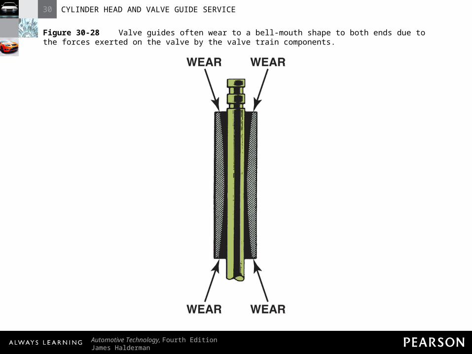
Figure 30-28 Valve guides often wear to a bell-mouth shape to both ends due to the forces exerted on the valve by the valve train components.
30 CYLINDER HEAD AND VALVE GUIDE SERVICE
Automotive Technology, Fourth EditionJames Halderman
© 2011 Pearson Education, Inc.All Rights Reserved
Valve GuidesValve Guides
• Valve Stem-to-Guide Clearance– Intake valve: 0.001 to 0.003 in. (0.025 to
0.076 mm)– Exhaust valve: 0.002 to 0.004 in. (0.05 to
0.1 mm)

30 CYLINDER HEAD AND VALVE GUIDE SERVICE
Automotive Technology, Fourth EditionJames Halderman
© 2011 Pearson Education, Inc.All Rights Reserved
Valve GuidesValve Guides
• HINT: A human hair is about 0.002 in. (0.05 mm) in diameter. Therefore, the typical clearance between a valve stem and the valve guide is only the thickness of a human hair.

30 CYLINDER HEAD AND VALVE GUIDE SERVICE
Automotive Technology, Fourth EditionJames Halderman
© 2011 Pearson Education, Inc.All Rights Reserved
Valve Guides Valve Guides
• Measuring Valve Guides– Measure valves for stem wear before
measuring valve guides– Valve guides are measured in the middle
with a small-hole gauge

30 CYLINDER HEAD AND VALVE GUIDE SERVICE
Automotive Technology, Fourth EditionJames Halderman
© 2011 Pearson Education, Inc.All Rights Reserved
Valve Guides Valve Guides
• Measuring Valve Guides– Gauge size is checked with a micrometer– Guide is then checked at each end

30 CYLINDER HEAD AND VALVE GUIDE SERVICE
Automotive Technology, Fourth EditionJames Halderman
© 2011 Pearson Education, Inc.All Rights Reserved
Valve Guides Valve Guides
• Measuring Valve Guides– Place expanded part of the ball crosswise
to the engine where the greatest amount of wear exists

30 CYLINDER HEAD AND VALVE GUIDE SERVICE
Automotive Technology, Fourth EditionJames Halderman
© 2011 Pearson Education, Inc.All Rights Reserved
Valve Guides Valve Guides
• Measuring Valve Guides– Valve stem diameter is subtracted from the
valve guide diameter– Valve stem-to-guide clearance can also be
checked using a dial indicator (gauge)
?

30 CYLINDER HEAD AND VALVE GUIDE SERVICE
Automotive Technology, Fourth EditionJames Halderman
© 2011 Pearson Education, Inc.All Rights Reserved
Figure 30-29 A small-hole gauge and a micrometer are being used to measure the valve guide. The guide should be measured in three places: at the top, middle, and bottom.

30 CYLINDER HEAD AND VALVE GUIDE SERVICE
Automotive Technology, Fourth EditionJames Halderman
© 2011 Pearson Education, Inc.All Rights Reserved
Figure 30-30 The diameter of the valve stem is being measured using a micrometer. The difference between the inside diameter of the valve guide and the diameter of the valve stem is the valve guide-to-stem clearance.

30 CYLINDER HEAD AND VALVE GUIDE SERVICE
Automotive Technology, Fourth EditionJames Halderman
© 2011 Pearson Education, Inc.All Rights Reserved
Figure 30-31 Measuring valve guide-to-stem clearance with a dial indicator while rocking the stem in the direction of normal thrust. The reading on the dial indicator should be compared to specifications because it does not give the guide-to-stem clearance directly. The valve is usually held open to its maximum operating lift.

30 CYLINDER HEAD AND VALVE GUIDE SERVICE
Automotive Technology, Fourth EditionJames Halderman
© 2011 Pearson Education, Inc.All Rights Reserved
Figure 30-32 Sectional view of a knurled valve guide.
30 CYLINDER HEAD AND VALVE GUIDE SERVICE
Automotive Technology, Fourth EditionJames Halderman
© 2011 Pearson Education, Inc.All Rights Reserved
Valve Guides Valve Guides
• Oversize Stem Valves– Some domestic manufacturers recommend
replacing worn valve guides with oversize (OS) stems
– Sizes include 0.003, 0.005, 0.015, and 0.03 in.
30 CYLINDER HEAD AND VALVE GUIDE SERVICE
Automotive Technology, Fourth EditionJames Halderman
© 2011 Pearson Education, Inc.All Rights Reserved
Valve Guides Valve Guides
• Oversize Stem Valves– Valve guide is reamed or honed to fit the
oversize stem – Clearance of the valve stem in the guide is
the same as the original

30 CYLINDER HEAD AND VALVE GUIDE SERVICE
Automotive Technology, Fourth EditionJames Halderman
© 2011 Pearson Education, Inc.All Rights Reserved
Valve Guides Valve Guides
• Oversize Stem Valves– Oil clearance and heat transfer properties
do not change
• NOTE: Many remanufacturers of cylinder heads use oversize valve stems to simplify production.
30 CYLINDER HEAD AND VALVE GUIDE SERVICE
Automotive Technology, Fourth EditionJames Halderman
© 2011 Pearson Education, Inc.All Rights Reserved
VALVE GUIDE VALVE GUIDE REPLACEMENTREPLACEMENT

30 CYLINDER HEAD AND VALVE GUIDE SERVICE
Automotive Technology, Fourth EditionJames Halderman
© 2011 Pearson Education, Inc.All Rights Reserved
Valve Guide Replacement Valve Guide Replacement
• Purpose– Replacement always recommended when
valve assembly is reconditioned

30 CYLINDER HEAD AND VALVE GUIDE SERVICE
Automotive Technology, Fourth EditionJames Halderman
© 2011 Pearson Education, Inc.All Rights Reserved
Valve Guide Replacement Valve Guide Replacement
• Purpose– Replacement valve guides can be installed
to repair worn integral guides

30 CYLINDER HEAD AND VALVE GUIDE SERVICE
Automotive Technology, Fourth EditionJames Halderman
© 2011 Pearson Education, Inc.All Rights Reserved
Valve Guide Replacement Valve Guide Replacement
• Valve Guide Sizes– Three common sizes:
• 5/16 or 0.313 in.• 11/32 or 0.343 in.• 3/8 or 0.375 in.

30 CYLINDER HEAD AND VALVE GUIDE SERVICE
Automotive Technology, Fourth EditionJames Halderman
© 2011 Pearson Education, Inc.All Rights Reserved
Figure 30-33 Valve guide replacement procedure.

30 CYLINDER HEAD AND VALVE GUIDE SERVICE
Automotive Technology, Fourth EditionJames Halderman
© 2011 Pearson Education, Inc.All Rights Reserved
Valve Guide ReplacementValve Guide Replacement
• Valve Guide Inserts– Integral valve guides can be reconditioned
with valve guide inserts– Two types commonly used:
• Thin-walled bronze alloy sleeve bushing

30 CYLINDER HEAD AND VALVE GUIDE SERVICE
Automotive Technology, Fourth EditionJames Halderman
© 2011 Pearson Education, Inc.All Rights Reserved
Valve Guide ReplacementValve Guide Replacement
• Valve Guide Inserts– Two types commonly used
• Spiral bronze alloy bushing
30 CYLINDER HEAD AND VALVE GUIDE SERVICE
Automotive Technology, Fourth EditionJames Halderman
© 2011 Pearson Education, Inc.All Rights Reserved
Valve Guide ReplacementValve Guide Replacement
• Valve Guide Inserts– Installation kit includes all necessary
reamers, installing sleeves, broaches, burnishing tools, and cutoff tools
– Valve guide must be bored to a large enough size to accept the thin-walled insert sleeve

30 CYLINDER HEAD AND VALVE GUIDE SERVICE
Automotive Technology, Fourth EditionJames Halderman
© 2011 Pearson Education, Inc.All Rights Reserved
Figure 30-34 A type of fixture required to bore the valve guide to accept a thin-walled insert sleeve.

30 CYLINDER HEAD AND VALVE GUIDE SERVICE
Automotive Technology, Fourth EditionJames Halderman
© 2011 Pearson Education, Inc.All Rights Reserved
Figure 30-35 Trimming the top of the thin-walled insert.

30 CYLINDER HEAD AND VALVE GUIDE SERVICE
Automotive Technology, Fourth EditionJames Halderman
© 2011 Pearson Education, Inc.All Rights Reserved
Valve Guide ReplacementValve Guide Replacement
• Spiral Bronze Insert Bushings– Screwed into a thread that is put in the
valve guide– Tightened on an inserting tool and screwed
into the spring end of the guide until the bottom is flush with the seat end

30 CYLINDER HEAD AND VALVE GUIDE SERVICE
Automotive Technology, Fourth EditionJames Halderman
© 2011 Pearson Education, Inc.All Rights Reserved
Valve Guide ReplacementValve Guide Replacement
• Spiral Bronze Insert Bushings– Bushing is trimmed to one coil above the
spring end of the guide– Bushing is temporarily secured with a
plastic serrated retainer and a worm gear clamp

30 CYLINDER HEAD AND VALVE GUIDE SERVICE
Automotive Technology, Fourth EditionJames Halderman
© 2011 Pearson Education, Inc.All Rights Reserved
Valve Guide ReplacementValve Guide Replacement
• Spiral Bronze Insert Bushings– Broach is driven through the bushing to
firmly seat it in the threads– Bushing is reamed or honed to size before
the retainer is removed

30 CYLINDER HEAD AND VALVE GUIDE SERVICE
Automotive Technology, Fourth EditionJames Halderman
© 2011 Pearson Education, Inc.All Rights Reserved
Valve Guide ReplacementValve Guide Replacement
• Spiral Bronze Insert Bushings– Final step is to trim the end with a special
cutoff tool