Haiti Shelter Initiative
76
HAITI SHELTER INITIATIVE SHELTER DESIGN/INSTRUCTION DOCUMENT (77 PAGES)
-
Upload
richelle-sibolboro -
Category
Documents
-
view
214 -
download
0
description
A final dossier that outlines how to create transitional shelters out of vernacular materials.
Transcript of Haiti Shelter Initiative

HAITI SHELTER INITIATIVE SHELTER DESIGN/INSTRUCTION DOCUMENT(77 PAGES)1. Place tarp on top of roof and tie/lash to structure. Ensure that there is some overhang on either side.
(option 1)
Assembly

TABLE OF CONTENTS HelloWho we AreContact Information Team + Labour BreakdownMaterials 1 Materials Needed 2 Tools 3-4Important Information Bamboo Prep 1 Diagram 2 Material amount + tools 3 -5 Cutting Lists 6 -8 Labeling 9-10 Notching Lashing 1 Instructions 2 Diagrams 3 PhotosColumn Assembly 1 Materials + Tools 2-5 3048 mm Columns (Columns A + B +E) 6-7 2718 mm Columns (Columns C + D) 8Waterproofing
Flooring 1 Materials + Tools 2 Concrete Information 3 Tire Anchor Assemby 4 -7Flooring Options 7 Finished Floor Roof Assembly 1 Materials + Tools 2-4 AssemblyStructure Assembly 1 Materials + Tools 2 Layout 3-5 Raising Columns + Roof 6-8 Top + Bottom Bracing, Squaring 9-11 Cross Bracing 12-13 Walls 14 Anchor Lashing Anchor to Roof Lashing Diagrams (4 pages) 15-16WallsandWaterproofingMultiple Unit Assembly 1 Structures of 2+ Units 2-6 Structures of 4+ Units Reference 1-3 Metric Plans + Elevations 4-6 Imperial Plans + ElevationsAcknowledgements/Rekonasans
This design and document are property of the Haiti Shelter Initiative. All rights reserved.

Hello Rea and everyone from SOPUDEP!
We hope this document finds you in a better place than in January. We can’t possibly begin to imagine how much you have all had to go through and our whole group admires all of you for your strength, courage, and tenacity. For the last four months we have been working on developing a temporary design for you that is easy to assemble, afford-able, transportable, strong, and easy to take apart should the need arise. We also wanted to create a design that you could use as a unit by-itself (as a shelter, perhaps), or join it with more of the same units to make a bigger space (for a classroom or anything you think you need). Our design is a guideline only. As long as the basic structural elements remain the same, if you need to adjust it or change it to suit your needs please feel free to do so. A single unit, when complete, should measure 10 feet by 10 feet by 10 feet (or about 3m x 3m x 3m). We chose to use a combination of cinderblocks and rubble for the under-part of the floor (or the subfloor) simply because through our research cinderblocks seemed to be readily available, and they are generally a uniform size and level enough to create a good floor. Bamboo is lightweight, strong, easy to work with, and cheap. It is also flexible, which means that if there is the unfortunate occurrence of another earthquake, it should be resistant to breakage or collapse. If it should collapse, it is lightweight and will not have the devastating effect of a con-crete or similarly heavy structure. We hope that this, in some small way, might help to provide some assistance. If you have any questions along the way, please feel free to contact us at any time.
Sincerely,Haiti Shelter Initiative
Kathlene McGuinness Jon Chan Enoch WongValerie Cardoz Anna Hill Professor Lorella Dicintio (supervising faculty)Clancy Snook Nathan Vanegdom Ksenia Eic Allison McMurterEvelyn Stewart Chris LeungGintare Ragainyte Joanna WenderskaRudy Lee Richelle Silbolbro
Introduction

The Haiti Shelter Initiative was undertaken by a group of Ryerson Interior De-sign and Architecture Students, as well as alumni and faculty. The project was developed in response to the devastation caused by the earthquake on January 12, 2010. Our group sought to use the skills we had developed through education and experience to aid the victims of this disaster. The ur-gent need for shelter at the SOPUDEP School focused our efforts on develop-ing temporary classrooms and living quarters for the displaced staff and stu-dents. It is our hope that these shelters will help the community at SOPUDEP rebuild and continue their important work.
WHO WE ARE

Contact Information
HAITI SHELTER INITIATIVE CONTACT INFORMATIONName Telephone E-Mail
Kathlene McGuinness 416-995-0056 [email protected] (COORDINATOR)Valerie Cardozo [email protected] (TEAM)Ksenia Eic [email protected] (TEAM)Anna Hill [email protected] (TEAM)Rudy Lee [email protected] (TEAM)Chris Leung [email protected] (TEAM)Allison McMurter [email protected] (TEAM)Gintare Ragainyte [email protected] (TEAM)Richelle Sibolboro [email protected] (TEAM)Clancy Snook [email protected] (TEAM)Nathan VanEgdom [email protected] (TEAM)Joanna Wenderska [email protected] (TEAM)Enoch Wong [email protected] (TEAM)
Prof. Lorella Dicintio [email protected] (SUPERVISING FACULTY)Ryan Sawatzky 1-705-345-5593 [email protected] (SAWARTZKY FOUNDATION)Junior Cantave 011-509-3604-1919 [email protected] (BAMBOO SUPPLIER)

1. Add extra rows of cinder blocks to support floor.2. Lay Cardboard sheets and a carpet or rug, if available, on top of cinder blocks.
Assembly
1 1
LABOUR + TEAM BREAKDOWN
Teams and Tasks• Theidealteamsizeforassemblingone structure is 8-10 people• Theroof,wallsandfloorcanbeassembled simultaneously by groups of 2-3• Thefloorassemblyrequiresheavylifting

MATERIALS NEEDED
Material Overview
MATERIALS 1
BAMBOOtotal 44 (48 SINGLE UNIT)
TARPSROOF: (x 1) 4678MMX3048
WALLS: (X3) 3658MMX3048MM (12’X10’)
TIRESx 4(SEE FLOORING SECTION)
CORRUGATED METAL
CINDER BLOCKS(SEE FLOORING 4-6)
RUBBLE(SEE FLOORING 4-6)
PLASTIC TWINE
CARDBOARD BOXES OR MATS/RUGS
A
B
C
D
E
F
G
H
PLASTIC BAGSX10-12
I
Teams and Tasks• Theidealteamsizeforassemblingone structure is 8-10 people• Theroof,wallsandfloorcanbeassembled simultaneously by groups of 2-3• Thefloorassemblyrequiresheavylifting
*for structures with four or more units, you will need at least eight 4678x3048mm tarps.
*

TOOLS NEEDED
Material Overview
MATERIALS 2
HAND OR ELECTRIC DRILL
LADDER
KNIFE
SCISSORS(KNIFE CAN BE USED)
STIR STICK
A
B
C
D
E
TAPE MEASUREROR ATTACHED RULER,PENCIL
HANDSAW OR ELECTRIC SAW
F
G
HHAMMER + NAIL(FOR PERFORATING METAL - OTHER TOOL COULD BE USED)

Material Overview
Bamboo is structurally strong, but to ensure that it is ideal for your use:
1. Bamboo should last for at least one year, providing that it is properly protected from the elements. a. Monitor the bamboo after three months to ensure that it is showing no signs of breakage, rotting, mould, etc.b. Replace individual pieces if there is strong evidence of any of these above-mentioned problems.
2. Make sure that the bamboo has completely cured before you use it. It should be cured by the time it arrives to you, but here are some ways to ensure that it is:a. The bamboo should not be green, but a golden tan color. If it is greenish, that means it has not totally cured. As bamboo cures, it shrinks, so if you use green bamboo to build the shelter, the joints will loosen as the material contracts, meaning that your shelter could collapse or become less stable.b. The bamboo should be extremely hard and sound like hollow wood when you knock on it. The material should be slightly flex-ible, but it should not bend too much or kink easily.
3. It is important that the bamboo be protected from moisture as much as possible.
a. As bamboo is technically a grass, and not a wood product, it absorbs moisture more quickly than a wood product might. If you take several plastic bags and place the bottom of each column inside them, tying it tightly, this should help to keep moisture away from the bottom of the structure.b. If it is exposed to moisture/ gets really wet, try and remove it or protect it from the source of moisture (i.e. elevate it out of a puddle, wrap some more plastic around it, ensure the tarps properly overlap the corners – as explained in the assembly diagrams and text). Also, when possible, expose it to the sun long enough for it to dry thoroughly.c. The eave extensions on the front of the roof piece, as well as the 2’-0” (60cm) tarp overhangs on the front and rear of the roof, are there to help protect the shelter (and the people inside of it) from the rain. d. The cinderblock holes should run in the direction of any slope in the ground the structure is standing on. The holes will help water to drain properly underneath the structure, and prevent water from pooling next to the structureand possibly flooding the inte-rior.
Material Overview
MATERIALS 3

Material Overview
4. Finally, if the cured bamboo has splits in it, that is fine structurally as long as:a. When you put notches (drill holes) into the bamboo for lashing purposes, make sure that the holes are not on the same side of the bamboo piece as the split. This will ensure that the bamboo piece stays structurally strong.b. Triple-check the marks for the notches before you drill them. Make sure all of the notches are going in the same direction (i.e. bottom notches are on the same sides of the bamboo as the top notches). If there are holes going the wrong way, you will have to make more, and the more holes there are in the bamboo, the less structurally sound it is.Twine and lashing:c. DO NOT USE NAILS IN THE BAMBOO. IT WILL SPLIT.
5. The material used to lash the joints should be a lightweight (ideally plastic) twine.a. This type of twine is small enough and flexible enough for these types of joints. Each joint will need approxi-mately 1-2 meters of twine, except for the anchor lashes which will need approximately 7-8 meters (there are six of these anchor lashes).
6. Ensure that you cinch the knot of every joint you lash.a. Cinching each knot is the difference between the joint being somewhat strong, and the joint being really strong and resistant to forces of wind, pressure, and degradation. It will also prevent each knot from sliding up and down the material.(SEE LASHING DIAGRAM ON PAGE...)
7. The lashing should last four to six months.a. Monitor the lashing after 3 months or so for signs of degradation (i.e. fraying, loosening, snapping, thinning) and replace as the need arises.b. Cinching the knots is VERY IMPORTANT!
MATERIALS 4

BAMBOO + NOTCHING DIAGRAMRefer to drawings on next few pages
Side elevation1:20
BAMBOO PREP 1

Bamboo #
BAMBOO # + CUTTING TOOLS
x 37(41 single unit)
x 4x4
x6 x5
10’x1”(3048mm x
25mm)
8’-11”x1” (2718mm x
25mm)4’x1”
(1219mmx25mm) 1’x1”
(305mm x 25mm)
6”x1”(229mm x
25mm)
x 44(48 single unit)
10’x1”(3048mm x 25mm)
all other sizes will be cut from these pieces
10'-0" (3040mm) 8'-0" (2348mm) 4'-0" (1219mm)6"(152.5mm)1'-0" (305mm)
x4
1’1”x1”(330mmx
25mm)
1'-1" (305mm)
TAPE MEASUREROR ATTACHED RULER,PENCIL
HANDSAW OR ELECTRIC SAW
BAMBOO PREP 2

Bamboo Cutlist
CUTLIST 1
x 4
x 4
x 4
x 410'-0" (3040mm)
1'-1" (330mm)
8'-11" (2718mm)
8'-11" (2718mm)
1'-1" (330mm)
Take 4 pieces of 10’-0” x 1” bamboo.
Cut all four pieces in two, one part 8’-11” (2718mm) and one part 1’-1” (330mm)
You will end up with four 2718mm (8’-11”)pieces.
You will now have four 330mm (1’-1”) pieces.
x 48'-11" (2718mm)
x 41'-1" (330mm)
You should now have four 2718mm (or 8’-11”) pieces, which will be used for the rear columns. Label these pieces with the number 2. You will have four 330mm (or 1’-1”) pieces, which will be used as bracing inside the columns. Label these pieces with the number 4.
CUTLIST ONEBAMBOO PREP 3

Bamboo Cutlist
x 2
x 2
1'-0" (305mm)
1'-0" (305mm)
Cut both of the 610mm pieces in half, with two pieces at 305mm (1’-0”).
4'-0" (1219mm)
4'-0" (1219mm)
2'-0" (610mm)
10'-0" (3040mm)
Take 2 pieces of 10’-0” x 1” bamboo. Cut both pieces into
three, two parts 4’-0” (1219mm) and one part 2’-0” (610mm)
x22'-0" (610mm)
You will now have two 610mm (2’-0”) pieces.
x 4
1'-0" (305mm)
You will now have four 305mm (1’-0”) pieces.
You will now have four 4’-0” (1219mm) pieces. Put them aside.
4'-0" (1219mm)
x 2
x 44'-0" (1219mm)
x 4
x 41'-0" (305mm)
You should now have four 1219mm (or 4’-0”) pieces, which will be used for the eaves. Label these pieces with the number 7. You will have four 305mm (or 1’-0”) pieces, which will be used as bracing inside the columns. Label THREE of these pieces with the number 3, and ONE with the number 4.
CUTLIST 2BAMBOO PREP 4
Bamboo Cutlist Bamboo Cutlist
x 110'-0" (3040mm)
Take 1 pieces of 10’-0” x 1” bamboo.
x 1
x 1
Cut the piece into six, one part at 5’-0” (1524mm) and �ve parts at 1’-0” (305mm).
You should now have SIX 152.5mm (or 6”) pieces, which will be used for the column bracing. Label FIVE of these pieces with the number 5. You will have ONE 8’-0” (or 2438mm)piece, which can be used (along with the remain-ing 152.5mm piece) to make repairs or replace lost parts.
10'-0" (3040mm)
1'-0" (305mm)
1'-0" (305mm)
1'-0" (305mm)
8'-0" (2438mm)
x 66"(152.5mm)
6"(152.5mm)
6"(152.5mm)
8'-0" (2438mm)
1'-0" (305mm)
Cut the 3 pieces of 1’-0” (305mm) in half, so you are left with six pieces of 6” (152.5mm).x 3
CUTLIST 2BAMBOO PREP 5

Bamboo Piece Labeling
LABELING 1
1'-0" (305mm) 6"(152.5mm)
8'-11" (2718mm)
Label 4 pieces of 8’-11” (2718mm) with the number 2.
Label 4 pieces of 1’-1” (330mm), AND one piece of 1’-0” (305mm) with the number 4.
1'-0" (305mm)
Label 8 pieces of 1’-0” (305mm) with the number 3.
Label 8 pieces of 6” (229mm) with the number 5.
1'-1" (330mm)
x 610'-0" (3040mm)
Label 6 pieces of 10’-0” (3048mm) with the number 1.
#1
x 4
#2 #3
x 3
#4
x 4 x 1 x 5
#5
BAMBOO PREP 6
Bamboo Piece Labeling
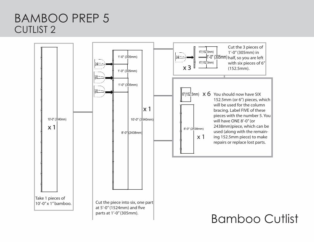
x 910'-0" (3040mm)
Label 9 pieces of 10’-0” (3048mm) with the number 6.
x10 (x14 single unit)
10'-0" (3040mm)
Label 10 pieces (14 if you are building a single unit) of 10’-0” (3048mm) with the number 10.
LABELING
x 210'-0" (3040mm)
Label 2 pieces of 10’-0” (3048mm) with the number 11.
x 510'-0" (3040mm)
Label 5 pieces of 10’-0” (3048mm) with the number 8.
x 410'-0" (3040mm)
Label 4 pieces of 10’-0” (3048mm) with the number 9.
#8#6 #9 #10 #11
4'-0" (1219mm)
Label 4 pieces of 4’-0” (1219mm) with the number 7.
x 4
#7
LABELING 2BAMBOO PREP 7
Bamboo Piece Labeling
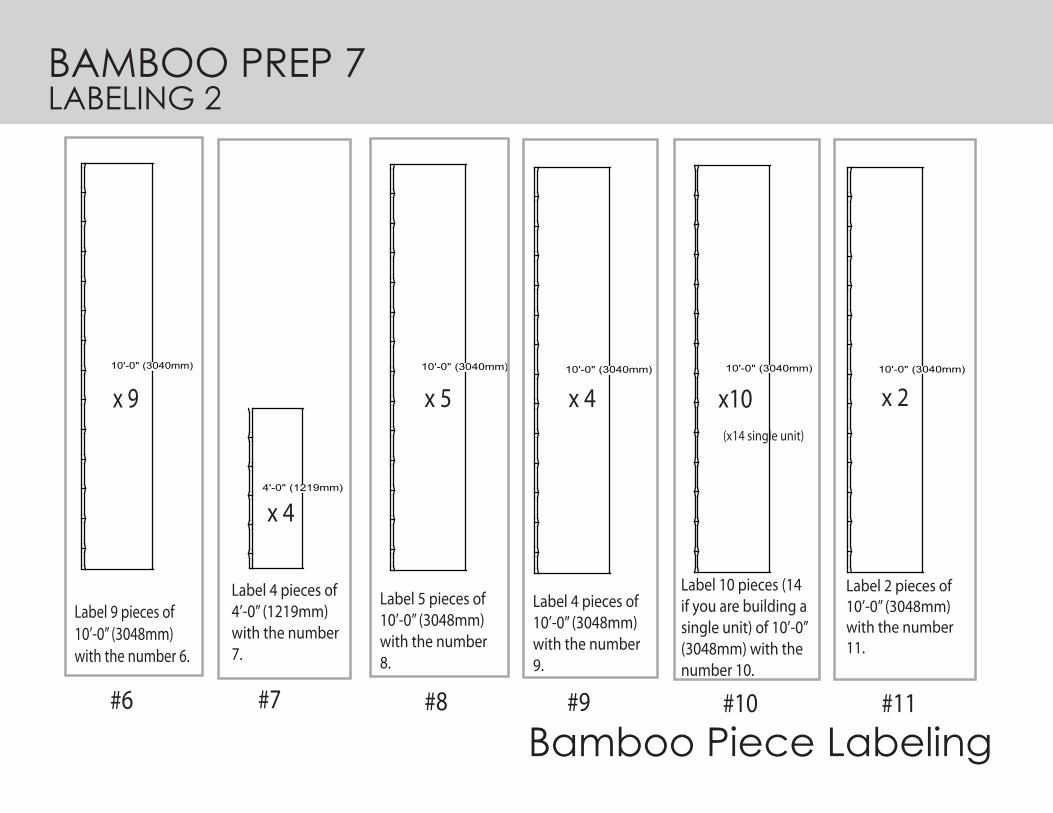
*You should have two extra pieces: one 8’-0” (2438mm), and one 6” (152.5mm) piece, which can be used for repairs or replacements.* When building a module of four or more units, two #1 pieces (3048mm) become two more # 2 pieces (2718mm)(for COLUMN E which moves to the rear of the structure)
BAMBOO PREP 8PIECES REFERENCE
BAMBOO NUMBERS
LENGTH NOTCH LOCATION
1 (x6)2 (x4)3 (x3)4 (x1) (x4)
5 (x5)
6 (x9)
7 (x4)8 (x5)9 (x4)
10 (x10) (14-single)
11 (x2)
30482718305305330
152.530481219304830483048
3048
BAMBOO LEGENDAND RULER
10 20 30 40 50mm 60 70 80 90 100 110 120 130 140 150 160 170 180 190 200 210 220 230 240 2500
229 & 610 from top178 from bottom
79.6 from top79.6 from bottom
(9" & 24" from top7" from bottom)
(3” from top3" from bottom)
(mm from ends) (inches from ends)(mm) (inches)
10'-0"
10'-0"
10'-0"
10'-0"
10'-0"
10'-0"
8'-11"
1’-0"
1’-0"
1’-11”
6”
4'-0"
279 from top178 from bottom
(11” from top 7” from bottom)
152.5 from top (6” from top)
178 from top (7” from top)
79.6 from top (3” from top)
AMOUNT

NOTCHING1
DRILL
#4
#2#1
#5#3
#11
KNIFE
TAPE MEASUREROR ATTACHED RULER,PENCIL
BAMBOO PIECES #1-5, 11
1. ALL NOTCHES ARE HOLES APPROXIMATELY 3-4 MM (1/4”) IN DIAMETER, DRILLED STRAIGHT THROUGH THE BAMBOO PIECE.
2. ALL NOTCHES ON EACH PIECE OF BAMBOO SHOULD BE DRILLED IN THE SAME DIRECTION.
MATERIALS NEEDED
BAMBOO PREP 9

6"(152.5mm)3" (79.6mm)
2’-0”(610mm)
9” (229mm)
7" (178MM)
10'-0" (3040mm) 8'-11" (2718mm)
11" (279mm)
7" (178MM)
1'-1" (305mm)7" (178mm)
10'-0" (3040mm)
3" (79.6mm)
3" (79.6mm)
Drill a notch through the 330 mm (1’-1”) pieces (pieces labelled #4) at 178mm fromt the top (7”). Do the same for the #4 bamboo piece that is 305mm (1’-0”) long
Drill a notch through the 152.5mm (6”)pieces (pieces labelled 5) halfway down the piece at 79,6mm (3”).
Drill a notch through the 3048 mm (10’-0”) pieces (pieces labelled 1) at 9” (229mm) from the top, another notch at 2’-0” (610mm) from the top, and one notch 7” (178mm) from the bottom.
Drill a notch through the 2718 mm (8’-11”) pieces (pieces labelled #2) at 11” (279mm) from the top, and one notch 7” (178mm) from the bottom.
Drill a notch through the 3048 mm (10’-0”) pieces (pieces labelled 11) at 3” (79.6mm) from the top, and one notch 3” ( 79.6mm) from the bottom.
1'-0" (305mm)6" (152.5mm)
Drill a notch through the 305 mm (1’-0”) pieces (pieces labelled #3) at 152.5mm fromt the top (6”).
1'-0" (305mm)7" (178mm)
Notching
NOTCHING 2
PIECE #3 PIECE #5
PIECE #11PIECE #2PIECE #1
PIECE #4
x6 x4 x2
x1x4 x5x3
BAMBOO PREP 10

1. Cut eighteen 2m pieces of rope for joinery of columns.2. Push one end of rope through holes in the middle brace.3. Pull the rope through until there is approximately 1m of rope on each side of the brace.4. Push one end of the twine through corresponding holes in longer piece.5. Wrap around the two pieces until secure, ensuring there is twine left for remaining lashing.6. Repeat for longer piece on other side of middle brace. 7. Using remaining twine, continue wrapping around all three pieces tightly together. 8. Alternate knotting and wrapping the ends as they go around the three pieces.9. Repeat steps 1-8 for all eighteen column braces.10. Most important step is to cinchthefinalknots(seeMaterial4):11. Cinch by cutting another piece of twine.12. Tightly wrap and tie twine around original lashing, between bamboo pieces. Do the same for lashing between the other two pieces of bamboo. 13. Continue this process for all the joints of the columns. 14. Theendresultisfivefullyassembledcolumns.
*For further information see Lashing Diagrams.
LASHING 1
1. Wrap twine around joint diagonally to hold connection in place, 2. Continue wrapping in opposite direction. Tie Knots frequently.3. Continue 1 + 2 until joint is completely cov ered4. Cinch lashing.
Lashing for other joints:

Lashing Diagrams
cinching*it is very important to cinch to strengthen
and tighten the lashing
LASHING 2
Columns

LASHING 3

#4
#2#1
#3#5 Plastic Twine
Bamboo Pieces #1-5
COLUMN ASSEMBLY 1MATERIALS NEEDED
B
A
A. Bamboo Pieces #1-5B. Plastic Twine
KNIFE
SCISSORS(KNIFE CAN BE USED)

1. To prepare for assembly first organize all pieces of columns on the ground.2. Separate the pieces according to their labels - separate piles for Piece #1 - 5.
1'-0" (305mm) 6"(152.5mm)
8'-11" (2718mm)
Label 4 pieces of 8’-11” (2718mm) with the number 2.
Label 4 pieces of 1’-1” (330mm), AND one piece of 1’-0” (305mm) with the number 4.
1'-0" (305mm)
Label 8 pieces of 1’-0” (305mm) with the number 3.
Label 8 pieces of 6” (229mm) with the number 5.
1'-1" (330mm)
x 610'-0" (3040mm)
Label 6 pieces of 10’-0” (3048mm) with the number 1.
#1
x 4
#2 #3
x 3
#4
x 4 x 1 x 5
#5
COLUMN ASSEMBLY 2

3048mm Column
1. Gather bamboo pieces #1(3048mm) 2. Lay two 3048mm pieces (Piece #1) parallel to each other on the ground, with their notches aligned.
3. Place one 305mm (1’-0”) middle brace (Piece #3) between the notching located on the two pieces.
4 Notches of the three pieces should line up.
COLUMN ASSEMBLY 33048MM (10’-0”) Column (A + B + E)

5. Place one 330mm (1’-1”)middle brace (Piece #4) below thefirstbrace(Piece#3).
6. The notching in the three pieces should match up.
7. Place one 152.5mm (6”) middle bracer (Piece 5) between the bottom of the two bamboo #1 pieces.8. Holes of the three pieces should match up.
COLUMN ASSEMBLY 43048MM (10’-0”) Column (A + B + E)
See COLUMN ASSEMBLY 5 for important info on Piece #4

COLUMN ASSEMBLY 53048MM (10’-0”) Column (A + B + E)
4 corner columns detailpiece #4: 13” (330mm) notched @ 7” (178mm) from top
Piece #4 - top of columns details 1:10
Column E detail - doorway columnpiece #4: 12” (305mm) notched @ 7” (178mm) from top
piece #4 piece #4
Piece #4 is 13” (330mm) in length for the four corner columns, but 12” (305mm) in length for column E- the doorway column. Please note that both are notched at 7” (178mm) from the top of the piece- ensure proper orientation when installing.
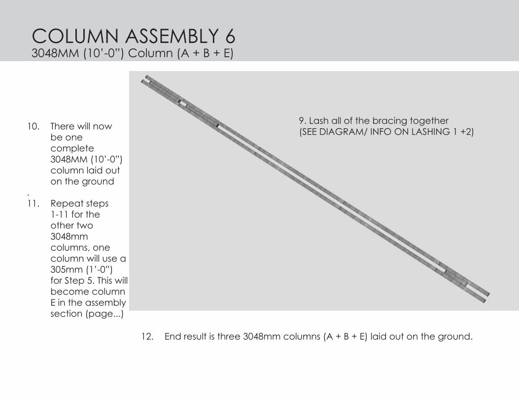
10. There will now be one complete 3048MM (10’-0”) column laid out on the ground.11. Repeat steps 1-11 for the other two 3048mm columns, one column will use a 305mm (1’-0”) for Step 5. This will become column E in the assembly section (page...)
12. End result is three 3048mm columns (A + B + E) laid out on the ground.
9. Lash all of the bracing together (SEE DIAGRAM/ INFO ON LASHING 1 +2)
COLUMN ASSEMBLY 63048MM (10’-0”) Column (A + B + E)

1. Gather the pieces of bamboo labeled #2.2. Lay two 2718mm (8’-11”) pieces (Piece #2 )parallel to each other on the ground. The notches in each piece should line up.
3. Place one 305mm (1’-0”) middle brace (Piece #4) in between the two #2 bamboo pieces, where the notches are 279mm (11”) from the end.
4. Notches of the three pieces should match up .
COLUMN ASSEMBLY 72718MM (8’-11”) Column (C + D)

5. Place one 152.5mm (6”) middle brace (Piece #5) between the bottom of the same pieces, where the notches are 178mm from the bottom.
8. Repeat steps for the other 2718mm columns (the last two pieces of #2 bamboo).
9. End result is two columns that measure 2438mm, which are columns C + D in the assembly diagrams.
COLUMN ASSEMBLY 82718MM (8’-11”) Column (C + D)
6. Notches of the three pieces should line up.
7. Lash all of the bracing together (SEE LASHING DIAGRAM ON PAGE...)

Wrap the bottom of each column in plastic bags, tied tightly at the top to prevent moisture from seeping inside. This will protect the structural integrity of the bamboo, as exposure to moisture can compromise the material.
COLUMN ASSEMBLY 9

FLOORING
Flooring Materials
200 mm
200 mm200 mm
410 mmBB
C
3048
mm
E
37.5mm
D
267mm
787 mm381 mm
AA
4 x TIRES: OUR DESIGN IS BASED ON AN AUTOMO-TIVE TIRE MEASURING 787MM DIAMETER X 267MM WIDTH (WITH A 381MM DIAMETER OPENING).
WIRE OR ROPE (NOT PLASTIC TWINE - IT SHOULD BE HEAVIER-DUTY), APPROXIMATELY 644MM LONG, FOLDED IN HALF AND TIED IN A TOGETHER @ THE BOTTOM.
SAND, GRAVEL, OR CONCRETE RUBBLE FOR FLOOR INFILL.
PIECE #11: TWO PIECES OF 10’-0” X 1” (3048MM X 26MM).
CINDERBLOCKS:SEE FLOORING OPTIONS ON THE FOLLOWING PAGES FOR AMOUNTS NEEDED.
MATERIALS NEEDED
1
ECARDBOARD BOXES OR MATS/RUGS FOR FINISHED FLOOR

The concrete should be composed of cement, course aggregate, fine aggregate and water
- Course Aggregates can include gravel, rubble, or crushed rock - Fine Aggregates can include fine or course sands
The cement should be stored off the ground in a well-aired, clean and dry place - wrapping the cement bags in plastic sheets provides extra protection
When mixing the dry ingredients, mix in a ratio of 1 part cement to 2 parts fine aggregate to 3 parts course aggregate
When adding water, add water slowly until the concrete is viscous enough to be poured into the rubber tire forms - use as little water as possible, only enough to make the mix workable as the more water that is used, the weaker the concrete will be
1.
2.
3.
4.
Tips For Making Concrete
..
..
FLOORING 2CONCRETE

Concrete Tire Anchors*note: place plastic bag underneath tire before pouring concrete to prevent concrete from setting directly onto the ground
1. Insert thick rope/wire into centre of tire 2. Hold thick rope/wire in place while pouring concrete to create a loop for latching3. Allow concrete to set before moving4. To move anchors, tilt tires upright to roll.
1. 2. 3.
4.
tie wire to hold shape if needed
NOTE: PLACE PLASTIC BAGUNDERNEATH TIRE WHENPOURING CONCRETE INTO TIRETO PREVENT CONCRETE FROMSTICKING TO THE GROUND
RUBBER TIRE
WIRE/ ROPE TO HOLD SHAPE OF THICK WIRE
CONCRETE
THICK WIRE
SECTION DETAIL OF TIRE BASE WITH CONCRETE AND METAL LOOP
267
787
381
214.5
166.5
SCALE: 1:5
NOTE: PLACE PLASTIC BAGUNDERNEATH TIRE WHENPOURING CONCRETE INTO TIRETO PREVENT CONCRETE FROMSTICKING TO THE GROUND
RUBBER TIRE
WIRE/ ROPE TO HOLD SHAPE OF THICK WIRE
CONCRETE
THICK WIRE
SECTION DETAIL OF TIRE BASE WITH CONCRETE AND METAL LOOP
267
787
381
214.5
166.5
SCALE: 1:5
NOTE: PLACE PLASTIC BAGUNDERNEATH TIRE WHENPOURING CONCRETE INTO TIRETO PREVENT CONCRETE FROMSTICKING TO THE GROUND
RUBBER TIRE
WIRE/ ROPE TO HOLD SHAPE OF THICK WIRE
CONCRETE
THICK WIRE
SECTION DETAIL OF TIRE BASE WITH CONCRETE AND METAL LOOP
267
787
381
214.5
166.5
SCALE: 1:5
FLOORING 3

FLOORING CINDERBLOCK LAYOUT OPTIONS FOR FOUNDATION
112 CINDER BLOCKS 102 CINDER BLOCKS 75 CINDER BLOCKS 70 CINDER BLOCKS
53 CINDER BLOCKS 50 CINDER BLOCKS 40 CINDER BLOCKS
LEGEND
RUBBER TIRE
CINDER BLOCK
INDICATES DIRECTIONOF SLOPE
BAMBOO DRAINAGE
RUBBLE
SCALE: 1:50
A x 112
112 CINDER BLOCKS 102 CINDER BLOCKS 75 CINDER BLOCKS 70 CINDER BLOCKS
53 CINDER BLOCKS 50 CINDER BLOCKS 40 CINDER BLOCKS
LEGEND
RUBBER TIRE
CINDER BLOCK
INDICATES DIRECTIONOF SLOPE
BAMBOO DRAINAGE
RUBBLE
SCALE: 1:50
x 102B
112 CINDER BLOCKS 102 CINDER BLOCKS 75 CINDER BLOCKS 70 CINDER BLOCKS
53 CINDER BLOCKS 50 CINDER BLOCKS 40 CINDER BLOCKS
LEGEND
RUBBER TIRE
CINDER BLOCK
INDICATES DIRECTIONOF SLOPE
BAMBOO DRAINAGE
RUBBLE
SCALE: 1:50
112 CINDER BLOCKS 102 CINDER BLOCKS 75 CINDER BLOCKS 70 CINDER BLOCKS
53 CINDER BLOCKS 50 CINDER BLOCKS 40 CINDER BLOCKS
LEGEND
RUBBER TIRE
CINDER BLOCK
INDICATES DIRECTIONOF SLOPE
BAMBOO DRAINAGE
RUBBLE
SCALE: 1:50
*note: ensure holes in cinderblocks line up arrow indicates direction of slope for drainage through cinderblock holes
4

FLOORING CINDERBLOCK LAYOUT OPTIONS FOR FOUNDATION
112 CINDER BLOCKS 102 CINDER BLOCKS 75 CINDER BLOCKS 70 CINDER BLOCKS
53 CINDER BLOCKS 50 CINDER BLOCKS 40 CINDER BLOCKS
LEGEND
RUBBER TIRE
CINDER BLOCK
INDICATES DIRECTIONOF SLOPE
BAMBOO DRAINAGE
RUBBLE
SCALE: 1:50
C x 75
x 70D
112 CINDER BLOCKS 102 CINDER BLOCKS 75 CINDER BLOCKS 70 CINDER BLOCKS
53 CINDER BLOCKS 50 CINDER BLOCKS 40 CINDER BLOCKS
LEGEND
RUBBER TIRE
CINDER BLOCK
INDICATES DIRECTIONOF SLOPE
BAMBOO DRAINAGE
RUBBLE
SCALE: 1:50
112 CINDER BLOCKS 102 CINDER BLOCKS 75 CINDER BLOCKS 70 CINDER BLOCKS
53 CINDER BLOCKS 50 CINDER BLOCKS 40 CINDER BLOCKS
LEGEND
RUBBER TIRE
CINDER BLOCK
INDICATES DIRECTIONOF SLOPE
BAMBOO DRAINAGE
RUBBLE
SCALE: 1:50
112 CINDER BLOCKS 102 CINDER BLOCKS 75 CINDER BLOCKS 70 CINDER BLOCKS
53 CINDER BLOCKS 50 CINDER BLOCKS 40 CINDER BLOCKS
LEGEND
RUBBER TIRE
CINDER BLOCK
INDICATES DIRECTIONOF SLOPE
BAMBOO DRAINAGE
RUBBLE
SCALE: 1:50
5

Construction Process
CINDERBLOCK LAYOUT OPTIONS FOR FOUNDATION FLOORING CINDERBLOCK LAYOUT OPTIONS FOR FOUNDATION 112 CINDER BLOCKS 102 CINDER BLOCKS 75 CINDER BLOCKS 70 CINDER BLOCKS
53 CINDER BLOCKS 50 CINDER BLOCKS 40 CINDER BLOCKS
LEGEND
RUBBER TIRE
CINDER BLOCK
INDICATES DIRECTIONOF SLOPE
BAMBOO DRAINAGE
RUBBLE
SCALE: 1:50
E x 53
112 CINDER BLOCKS 102 CINDER BLOCKS 75 CINDER BLOCKS 70 CINDER BLOCKS
53 CINDER BLOCKS 50 CINDER BLOCKS 40 CINDER BLOCKS
LEGEND
RUBBER TIRE
CINDER BLOCK
INDICATES DIRECTIONOF SLOPE
BAMBOO DRAINAGE
RUBBLE
SCALE: 1:50
x 50F
112 CINDER BLOCKS 102 CINDER BLOCKS 75 CINDER BLOCKS 70 CINDER BLOCKS
53 CINDER BLOCKS 50 CINDER BLOCKS 40 CINDER BLOCKS
LEGEND
RUBBER TIRE
CINDER BLOCK
INDICATES DIRECTIONOF SLOPE
BAMBOO DRAINAGE
RUBBLE
SCALE: 1:50
112 CINDER BLOCKS 102 CINDER BLOCKS 75 CINDER BLOCKS 70 CINDER BLOCKS
53 CINDER BLOCKS 50 CINDER BLOCKS 40 CINDER BLOCKS
LEGEND
RUBBER TIRE
CINDER BLOCK
INDICATES DIRECTIONOF SLOPE
BAMBOO DRAINAGE
RUBBLE
SCALE: 1:50
6

Construction Process
FLOORING CINDERBLOCK LAYOUT OPTIONS FOR FOUNDATION112 CINDER BLOCKS 102 CINDER BLOCKS 75 CINDER BLOCKS 70 CINDER BLOCKS
53 CINDER BLOCKS 50 CINDER BLOCKS 40 CINDER BLOCKS
LEGEND
RUBBER TIRE
CINDER BLOCK
INDICATES DIRECTIONOF SLOPE
BAMBOO DRAINAGE
RUBBLE
SCALE: 1:50
G x 40
112 CINDER BLOCKS 102 CINDER BLOCKS 75 CINDER BLOCKS 70 CINDER BLOCKS
53 CINDER BLOCKS 50 CINDER BLOCKS 40 CINDER BLOCKS
LEGEND
RUBBER TIRE
CINDER BLOCK
INDICATES DIRECTIONOF SLOPE
BAMBOO DRAINAGE
RUBBLE
SCALE: 1:50
112 CINDER BLOCKS 102 CINDER BLOCKS 75 CINDER BLOCKS 70 CINDER BLOCKS
53 CINDER BLOCKS 50 CINDER BLOCKS 40 CINDER BLOCKS
LEGEND
RUBBER TIRE
CINDER BLOCK
INDICATES DIRECTIONOF SLOPE
BAMBOO DRAINAGE
RUBBLE
SCALE: 1:50
finished floorwith cardboard/mat over
cinderblock foundation
7

You will need:1. 8 pieces of #6.2. 4 pieces of #7.3. Twine.5. Tarp.
#7
#6Plastic TwineBamboo Pieces #6-7
Plastic Tarp (larger than 4267mm x 3048mm (14’x10’) or a # of tarpsthatwillequalthissize)
ROOF ASSEMBLY 1MATERIALS NEEDED
KNIFE
TAPE MEASUREROR ATTACHED RULER,PENCIL

You will need:1. 8 pieces of #6.2. 4 pieces of #7.3. Twine.5. Tarp.
1. Place 4 pieces horizontally. 1. Place 4 pieces vertically on top.2. Space them approx 3’-0” apart.
1. Allow for approx. 10 cm overlap around the perimeter.2. Use approx. 2 m of twine to tie the pieces together.
ROOF ASSEMBLY 2
(PIECE # 6) (PIECE # 6)914MM

1. Use bamboo pieces #7 (4’-0” x 1” or 1219MM x 26MM)and attach outside of vertical frame and keep 2 1/2” (100MM) overhang for binder.2. Tie all points of connection using 2 pieces of plastic twine (approx. 2 M long)for each one.
1. Rotate the grid 180 degrees.(Where the 4 original horizontal pieces are now on top.)
(PIECE # 7)
ROOF ASSEMBLY 3

1. Add tarp. Leave 2’-0” overhangon the front and rear of the structure.2. Tie tarp to frame.
ROOF ASSEMBLY 4
610MM
STRUCTURE ASSEMBLY 1
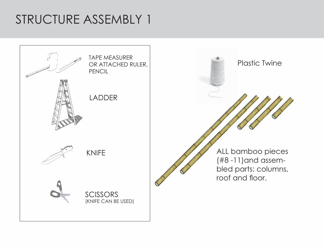
TAPE MEASUREROR ATTACHED RULER,PENCIL
LADDER
Plastic Twine
ALL bamboo pieces (#8 -11)and assem-bled parts: columns, roofandfloor.
KNIFE
SCISSORS(KNIFE CAN BE USED)

1. Place the roof frame on the ground, with the tarp side facing toward the sky.2. Lie the 3048mm (10’-0”) columns (A + B) on the ground, with the top of the columns facing toward the side of the roof with the eave extensions.3. Place the top bracing pieces through columns A, B + E, but do not lash them to the columns at this time.4. Place the 2718mm (8’-11”) columns (C + D) on the ground, with the tops facing toward the rear of the roof frame. 5. Place the top bracing (bamboo piece #8) through columns C+D, but do not lash them to the columns at this time.
1
2
34
5
A
B
CD
E
STRUCTURE ASSEMBLY 2

6. With a person holding each column, and two-to-four people holding the roof, lift the roof slightly and scoop the 3048mm (10’-0”) columns under the roof frame, sliding the columns onto the roof frame, with columns A+B hooking onto the inside of the perimeter of the roof frame (see detail bubble)
A
B
CD
E 6
STRUCTURE ASSEMBLY 3

7. At the same time, slide the 2718mm (8’-11”) columns (C + D) onto the rear part of the roof frame, ensuring the columns hook into the inside of the roof frame perimeter.
8. Lift the columns and the roof frame simultaneously.
A A
A
B B B
CCC
E
EE
D DD
7 86
STRUCTURE ASSEMBLY 4

9. Elevate the structure until the columns are perpendicular to the ground and the roof is sitting on top of the columns.
A B CDE
9
STRUCTURE ASSEMBLY 5

CDA
BE
10. Feed the remaining top brace (bamboo piece #8) through the hole between the two middle braces at the tops of columns A, B + E, and lash the brace to the columns at numbered points.
11. Lash the bottom brace (bamboo piece #9) between A, B + E to the top of the 152mm (6”) mid-dle brace at the bottom of each column, making sure that the brace extends an equal distance (ap-proximately 8-10cm) past both columns A + B. Do the same with the bottom brace between columns C + D.
10
111. Slide bamboo piece through bottom of columns.
Assembly
1. Slide bamboo piece through bottom of columns.
Assembly
1. Slide bamboo piece through bottom of columns.
Assembly
A
BE A
BE
A
BE
11
STRUCTURE ASSEMBLY 6

AB
CD
E
13. Feed the upper bracing (bamboo piece #8) through columns B + C, and at the same time feed the upper brace through A + D, then lash the braces to their respective columns.
12. Square the structure: measure the dis-tance between the columns and ensure they are the same. Mark the points on the ground (which are square) and have the people holding the columns ensure that the columns remain on these marks for the remainder of the assembly of the frame.
13
STRUCTURE ASSEMBLY 7

14. Add the bottom braces (piece #9) between columns A + D and between B + C, lashing them to the respective columns.
14
CD
AB
E 1.Placebamboopieceontopofthetwohorizontalpiecesthatwerejustadded.2. Tie/lash to columns and perpendicular bamboo pieces where circled.
Assembly1.Placebamboopieceontopofthetwohorizontalpiecesthatwerejustadded.
Assembly
14
STRUCTURE ASSEMBLY 8
C

STRUCTURE ASSEMBLY 9
1. Attach bracing pieces to three walls. Leave one side perpendicular to the 10’ wall open to allow for expansion later.2. Have someone hold the two pieces of bamboo for bracing as another ties them together in the centre where they overlap.3. Tie/lash bracing to columns.
12
3
3
3
3
33
3
3
33
Assembly Cross-bracing
3333

STRUCTURE ASSEMBLY 10CROSS-BRACING

15. Add the cross-bracing : take four pieces of 10’ x 1” bamboo, and create a cross brace that spans the entire diagonal lengths of each wall. Lash the cross-bracing in the center, and attwo evenly spaced points along where the extension of the cross brace meets the centralstructure of the cross-brace.
17. The cross-bracing on the front part of the structure (where the door frame is) should only require two pieces of 10’x1” (bamboo piece #10).
18. If the structure is to be part of a module (i.e. more than one unit), cross-bracing is not required on the wall which will be joined with the second unit. Instead, lash the columns of the facing walls together. 19. If the single unit will stand alone, all four sides of the structure must have cross-bracing, or if there is no more bamboo material, a corrugated metal piece that is large enough to span the length of the wall can be punctured and lashed to the frame at every 16”, with the corrugation perpendicular to the ground.
STRUCTURE ASSEMBLY 11CROSS-BRACING

Assembly
11 2
22
2
1. Place cinder/concrete blocks under structure. Have them span the whole length and align with one another.2. Fill tires with concrete and allow to harden. Mark on the ground the exact locations to place them. Lift the structure and place the corner columns on the centres.
11 2
22
2
20. Before any corrugated metal or tarp is added to the walls of the structure, the frame mustbetakenandplacedontopofthefloorstructure,withthefourexteriorcolumnscen-tered on top the tire anchors. IF YOU ARE BUILDING A MODULAR UNIT (TWO OR MORE UNITS JOINED TOGETHER) SEE STEP 28 BEFORE ADVANCING FURTHER.
21. Lash the frame to the tire, wrapping the twine from the loop in the tire anchor, all the way around the top of the structure (over the roof frame) and back to the tire anchor again. Do this for each of the four exterior columns (see STRUCTURE ASSEMBLY 14 + ANCHOR-TO ROOF-LASHING).
20
STRUCTURE ASSEMBLY 12CROSS-BRACING/WALLS
Assembly
11 2
22
2
1. Place cinder/concrete blocks under structure. Have them span the whole length and align with one another.2. Fill tires with concrete and allow to harden. Mark on the ground the exact locations to place them. Lift the structure and place the corner columns on the centres.
11 2
22
2

STRUCTURE ASSEMBLY 13CROSS-BRACING/WALLS
1. Place tarp on top of roof and tie/lash to structure. Ensure that there is some overhang on either side. (option 1)
Assembly

Assembly
11 2
22
2
1. Place cinder/concrete blocks under structure. Have them span the whole length and align with one another.2. Fill tires with concrete and allow to harden. Mark on the ground the exact locations to place them. Lift the structure and place the corner columns on the centres.
11 2
22
2
22. if the slope runs from the front to the rear of the structure, run bamboo pieces #11 (3048mm) through the aligned holes in the cinderblock. One piece (F) should butt up against the bottom of the door frame column. The other (G) should run close to column A. If the slope runs from the right to the left, refer to the Anchor to Roof lashing diagrams (p. 58 - 60) .
the structure and place the corner columns on the centres. the structure and place the corner columns on the centres. the structure and place the corner columns on the centres. the structure and place the corner columns on the centres. the structure and place the corner columns on the centres.
22
C
D
A
B
E
FG
23. Lash bamboo piece F to the roof frame, looping over the roof pieces connected to the joint joining column E to the roof. On the other side (rear of the shelter), lash bamboo piece F by looping over the roof pieces on the nearest roof joint.
24. Lash bamboo piece G to the roof frame, looping over the roof pieces connected to the joint joining column A to the roof. On the other side (rear of the shelter) lash bamboo piece G by looping it over the roof pieces connected to the joint joining column D to the roof.
2324
STRUCTURE ASSEMBLY 14CROSS-BRACING/WALLS
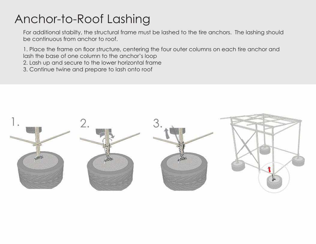
Anchor-to-Roof Lashing
1. Place the frame on floor structure, centering the four outer columns on each tire anchor and lash the base of one column to the anchor’s loop 2. Lash up and secure to the lower horizontal frame3. Continue twine and prepare to lash onto roof
1. 2. 3.
For additional stabilty, the structural frame must be lashed to the tire anchors. The lashing should be continuous from anchor to roof.
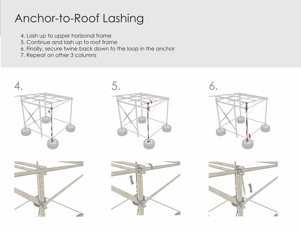
21Anchor-to-Roof Lashing4. Lash up to upper horizonal frame 5. Continue and lash up to roof frame6. Finally, secure twine back down to the loop in the anchor7. Repeat on other 3 columns
4. 5. 6.

Anchor-to-Roof Lashing
1. Tie twine to notched bamboo pieces fed through cinderblocks 2. Pull bamboo up and prepare to lash onto roof frame
1. & 2.
The 2 bamboo pieces inserted through the cinderblock foundation shoud also be lashed to the roof for stability.

Anchor-to-Roof Lashing3. Lash onto roof frame 4. Lash twine back down onto bamboo pieces in foundation
3. 4.

1. Place tarp on top of roof and tie/lash to structure. Ensure that there is some overhang on either side. (option 1)
Assembly
25. Add the tarps or corrugated metal to the walls. For the tarps, ensure that the tarps overlap on the corners of the structure to prevent rain from entering the structure. For tarps and corru-gatedmetal,leavetheareaabovethefirsttopbraceexposedforventilation.
25
26. The door can be left open or a tarp or other waterproof material may be used to cover it. A corrugated metal piece suspended from the top of the door frame (like a trap door) might be a good way to create a strong door if needed.
STRUCTURE ASSEMBLY 15CROSS-BRACING/WALLS

27. In preparation for heavy rains, attach the tarp so that a portion equal to the area ex-posed for ventilation is folded over at the top of the tarp, so that it can be lashed over the ventilation opening in times of heavy rain.
STRUCTURE ASSEMBLY 16CROSS-BRACING/WALLS

Example of expanded unit with addition of a second identicle structure.
12
3
3
3
3
33
3
33 3
Assembly
28. To attach two units to-gether, simply lash the col-umnsA+Dofthefirststruc-ture to columns B + C of the second structure, and then place it on the tires + add the wall membranes.
29. To create a 4 unit struc-ture, create two of these two unit attachments. (See
.
C DAB
MULTIPLE UNIT ASSEMBLY 12 UNITS
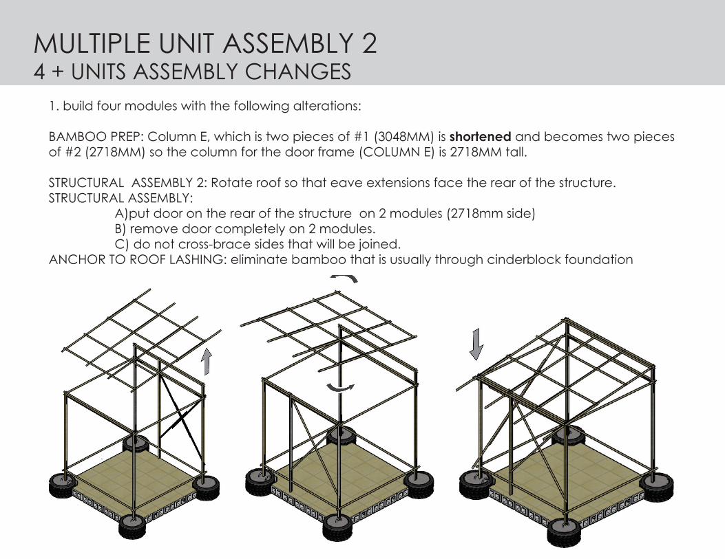
1. build four modules with the following alterations:
BAMBOO PREP: Column E, which is two pieces of #1 (3048MM) is shortened and becomes two pieces of #2 (2718MM) so the column for the door frame (COLUMN E) is 2718MM tall.
STRUCTURAL ASSEMBLY 2: Rotate roof so that eave extensions face the rear of the structure.STRUCTURAL ASSEMBLY: A)put door on the rear of the structure on 2 modules (2718mm side) B) remove door completely on 2 modules. C) do not cross-brace sides that will be joined. ANCHOR TO ROOF LASHING: eliminate bamboo that is usually through cinderblock foundation
MULTIPLE UNIT ASSEMBLY 24 + UNITS ASSEMBLY CHANGES
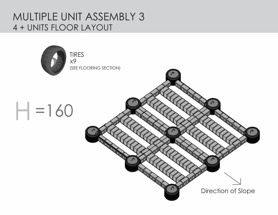
MULTIPLE UNIT ASSEMBLY 34 + UNITS FLOOR LAYOUT
H =160
Direction of Slope
TIRES
(SEE FLOORING SECTION)x9
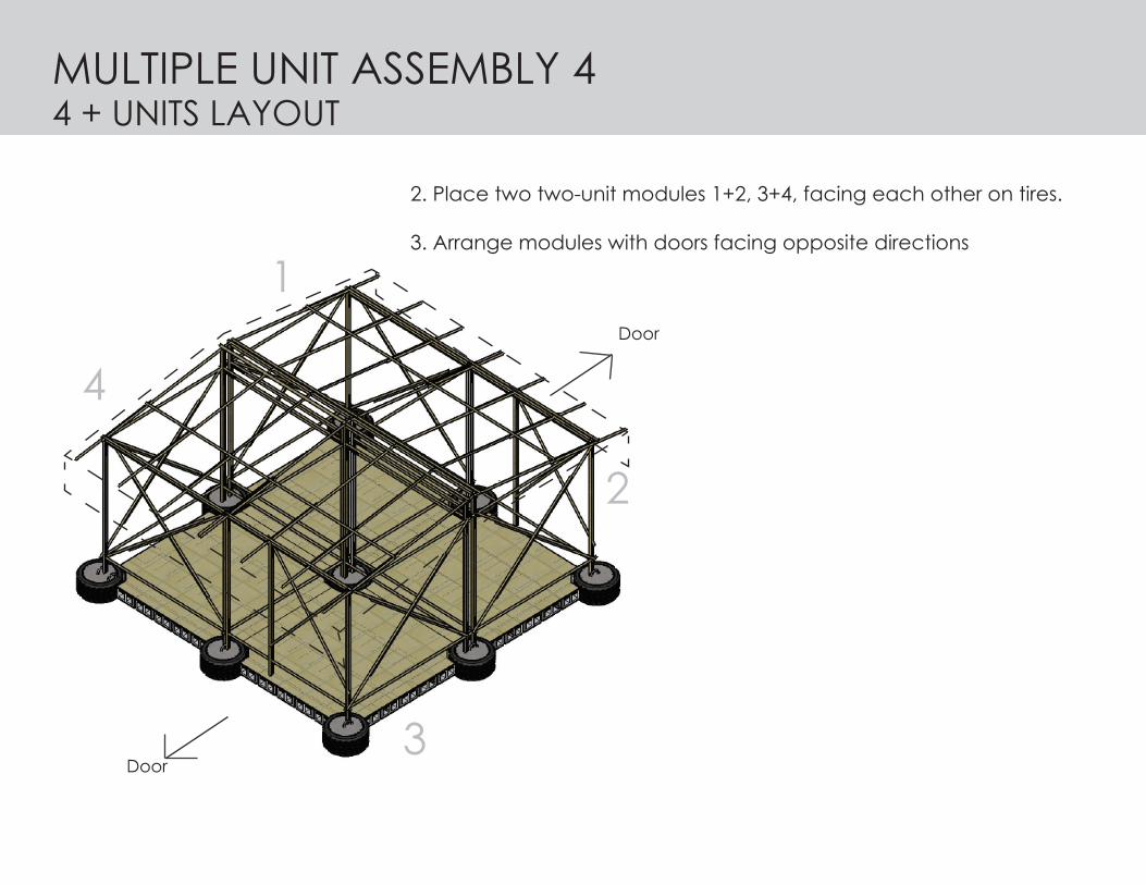
2. Place two two-unit modules 1+2, 3+4, facing each other on tires.
3. Arrange modules with doors facing opposite directions
Door
Door
1
2
3
4
MULTIPLE UNIT ASSEMBLY 44 + UNITS LAYOUT

4. Tire lashing joints should extend over both modules where columns meet at points 1-5 (see ANCHOR TO ROOF LASHING)
1
2
3
4
5
MULTIPLE UNIT ASSEMBLY 54 + UNITS LASHING

5. Attach additional tarps over center peak of structure to cover any gaps.
6. Make sure that the tarps on top cover any gaps, seams or openings between the tarps under-neath to prevent rainwater from leaking in (2+3).
MULTIPLE UNIT ASSEMBLY 64 + UNITS LAYOUT

ELEVATIONS- metric
FRONT ELEVATION1:25
REFERENCE 2ELEVATIONS
Front elevation1:25

ELEVATIONS - metric
SIDE ELEVATION1:25
Side elevation1:20
REFERENCE 1

PLAN - metric
plan1:20
PLAN1:25
REFERENCE 3

ELEVATIONS - imperial
SIDE ELEVATION1/2” = 1’-0”
ELEVATIONS
Side elevation1/2” = 1’-0”
REFERENCE 4

ELEVATIONS - imperial
FRONT ELEVATION1/2” = 1’-0”
REFERENCE 5

PLAN
Plan1/2” = 1’-0”
PLAN - imperial
PLAN1:25
REFERENCE 6

1. Place tarp on top of roof and tie/lash to structure. Ensure that there is some overhang on either side. (option 1)
Assembly
ACKNOWLEDGEMENTS/REKONESANSTHANK-YOU!
ReaDol,SOPUDEP,RyanSawatzky,DavidBowick,LorellaDicintio,CatherineDowling,MonicaPolo,JanaMacalik,AnnickMitchell,FilizKlassen,BarbaraVogel,ArleneDougall,JuniorCantave,ShirleyLewchuck,LiJing,MuhammedAliAumeer,CarolynRoche,MartineCordozo,JoelleDeas,MarkGorgolewski,NegarShakoori,Maj.JamesSimiana,ChristopherLa-roche,ErinAnnHampson,MarkusDoerr,ShawnMandelbaum,MaryMcNeill-Knowles,Rowena(WingSze)AuYeung,andeveryone in Haiti and Canada who have worked so hard and helped so much!
This document is property of the Haiti Shelter Initiative. All rights reserved.