HAFLER TRM6 (Transana Reference Monitor)Crossover Frequency 3.2kHz Crossover Slope 24dB/octave...
36
® MONITORING SYSTEM TRM6 Installation & Operation MONITORING SYS DESIGNED AND ASSEMBLED IN THE USA ®
Transcript of HAFLER TRM6 (Transana Reference Monitor)Crossover Frequency 3.2kHz Crossover Slope 24dB/octave...

®
MONITORING SYSTEM
TRM6Installation & Operation
MONITORING SYS
DESIGNED AND
ASSEMBLED IN THE
USA
®

Declaration of Conformity
Application of Council Directive: 73/23/EEC (low voltage directive)
Standard(s) to which Conformity is Declared: EN55103-1
EN55103-2
EN60065 (safety)
Manufacturer’s Name: Hafler
Manufacturer’s Address: 546 South Rockford Drive, Tempe, Arizona 85281, U.S.A.
Importer’s Name: _______________________________________________________
Importer’s Address: _______________________________________________________
Type of Equipment: 2-channel Audio Power Amplifier/Speaker
Model No.: TRM6
Serial Number:
Year of Manufacture: 1998 1999 2000 2001 2002
I, the undersigned, hereby declare that the equipment specified above conformsto the above Directive(s) and Standard(s)
Place: Hafler
12/01/98Date: James C. Strickland, VP Engineering

TRM6Free Field Frequency Response 55Hz-21kHz, ±2dBPeak Acoustic Output ≥119dB (per pair w/music @ 1m)Total Harmonic Distortion (THD) <0.5%, 150Hz-21kHz (90dB @ 1m on axis)High Frequency Driver 1" (25mm) Vifa Soft DomeLow Frequency Driver 6.5" (165mm) Polypropylene Cone/
Inverted Nitrile Rubber SurroundMagnetically Shielded
Cabinet 0.26 ft3 (7.3 liters) VentedFront Panel: Power Switch
System LED (Power/Clip/Thermal)
Rear Panel: XLR Balanced InputRCA Unbalanced JackUnbalanced/Balanced DIP SwitchInput Sensitivity DIP SwitchesBass Rolloff DIP SwitchesBass Shelving DIP SwitchesTreble Shelving DIP SwitchesIEC Standard Line Input / AC Line Fuse
Dimensions 8.875"W x 13.25"H x 11.50"D(22.54cm x 33.65cm x 29.21cm)
Net Weight 23 lbs. (10.43kg)
AMPLIFIER SECTIONPower Rating FTC (20Hz-20kHz, 0.1% THD)
35 Watts RMS @ 6 ohms (high frequency)50 Watts RMS @ 4 ohms (low frequency)
Signal-to-Noise >100dBCMRR >70dB typical @ 1kHzInput Impedance 47kΩ per phase balanced, 47kΩ unbalancedInput Sensitivity Range 500mV to 3V (unbalanced)
275mV to 1.5V (per phase balanced)(+4dB, +1dB, –2dB, –5dB, –8dB, –11dB)
Gain +33dB max. to +18dB min.Power Consumption Idle Power: 11W / 150mA @ 115 VAC (both channels driven) Idle Power: 11W / 75mA @ 230 VAC
Normal Operation: 55W / 600mA @ 120 VACNormal Operation: 54W / 310mA @ 230VACFull Power: 139W / 1.37A @ 120VACFull Power: 130W / 680mA @ 230VAC
CROSSOVER SECTIONCrossover Frequency 3.2kHzCrossover Slope 24dB/octave Linkwitz-RileySubsonic Filter Selectable 30Hz or 60Hz @ 12dB/octaveBass Shelving 30Hz to 200Hz, ±4dB
(+4dB, +2dB, 0dB, –2dB, –4dB)Treble Shelving 5kHz to 20kHz, ±4dB
(+4dB, +2dB, 0dB, –2dB, –4dB)
P E R F O R M A N C E S P E C I F I C A T I O N S
– i –Specifications are subject to change without notice.
Frequency Response@ 1m on axis
Horizontal Polar Response
Energy Time Curve
Dimensions
Side ViewFront View
13.25”
8.875” 11.50”

NOTICE - IMPORTANT SAFETY INFORMATION
1. READ INSTRUCTIONSAll the safety and operating instructions of your Hafler equipmentshould be read before power is applied to the equipment.
2. RETAIN OWNER'S MANUALThese safety and operating instructions should be retained forfuture reference.
3. HEED WARNINGSAll warnings on the equipment and in the operating instructions areimportant and should be followed.
4. FOLLOW INSTRUCTIONSAll operating and use instructions are important and should befollowed.
5. HEATThe equipment should be kept away from areas of high tempera-ture, i.e., heater vents, radiators, stoves/ovens, fireplaces, etc.
6. VENTILATIONThe equipment should be used in an area suitable for properventilation. Care should be taken not to impede airflow in andaround the cabinet.
7. WATER AND MOISTUREThe equipment should not be used in or around water, such as abathtub, sink, or swimming area. Also, the equipment should notbe used in areas prone to flooding, such as a basement.
8. POWER SOURCESThe equipment should be connected only to a power source of thesame voltage and frequency as that listed on the rear panel abovethe power cord entry point.
9. POWER CORD PROTECTIONPower cords should be arranged so they do not interfere with themovement of objects in the room: people, fan blades, utility carts,etc. Also, care should be taken that the cord is not pinched or cut,and placed so it is not in danger of being pinched or cut, as in undera rug, around a tight corner, etc.
10. POWER CORD GROUNDINGThe power supply cord is of a three wire grounded type, designedto reduce the risk of electric shock sustained from a live cabinet. Itis assumed to be of suitable length for most uses of the equipment.The use of extension cords and power strips is discouraged unlessthey are of suitable rating to deliver the required total current forsafe operation of all connected equipment. Furthermore, extensioncords or power strips must provide the same three wire grounded
connection. It is important that the blades of the equipment’s plugbe able to fully insert into the mating receptacle. Never remove theround grounding pin on the plug in an attempt to mate to a twowire ungrounded receptacle: use a grounding adaptor with thegrounding tab or wire suitably connected to earth ground.
11. NON-USE PERIODSDuring periods of extended non-use, the power cord should beunplugged from the power source.
12. CLEANINGThe equipment should be cleaned only as detailed in the operatinginstructions.
13. OBJECT AND LIQUID ENTRYCare should be taken so that objects and/or liquids, such as cleaningfluids or beverages, are not spilled into the enclosure of theequipment.
14. DAMAGE REQUIRING SERVICEHafler equipment should be serviced by qualified service personnelwhen:
A. The power supply cord or plug has been damaged, or
B. Objects have fallen onto, or liquid has been spilled into theequipment, or
C. The equipment has been exposed to rain, or
D. The equipment does not appear to operate normally orexhibits a marked change in performance, or
E. The equipment has been dropped, or the enclosure hasbeen damaged.
15. SERVICINGThe user should not attempt to service the equipment beyond thatwhich is described in the operating instructions. All other serviceshould be referred to qualified service personnel.
16. CARTS AND STANDSThe equipment should be used with carts or stands only of sufficientstrength and stability for the use intended.
An equipment and cart combination should be moved with care.Quick stops and starts, excessive force, and uneven surfaces may
cause the equipment and cart combination to topple.
– ii –
The lightning flash with arrowhead symbol within an equilateral triangleis intended to alert the user to the presence of uninsulated "dangerousvoltage" within the product's enclosure, that may be of sufficient magni-tude to constitute a risk of electric shock to persons.
The exclamation point within an equilateral triangle is intended to alertthe user of the presence of important operating and maintenance(servicing) instructions in the literature accompanying the appliance.
C A U T I O NRISK OF ELECTRIC SHOCK
DO NOT OPEN
WARNING: TO PREVENT FIRE OR SHOCK HAZARD DO NOT EXPOSE THIS EQUIPMENT TO RAIN OR MOISTURE.
!

– iii –
ADVERTENCIA – INFORMACION DE SEGURIDAD IMPORTANTE
1. LEA LAS INSTRUCCIONESTodas las instrucciones de seguidad y operación de su equipoHafler, deben ser leídas antes de que el equipo sea conectadodléctricamente.
2. CONSERVE EL MANUAL DEL PROPIETARIOEstas instrucciones de seguridad y operación, deben ser conservadaspara futuras referencias.
3. CUADROS DE ADVERTENCIASTodas las advertencias en el equipo y en las instrucciones deoperación, son importantes y deben ser seguidas.
4. SIGA LAS INSTRUCCIONESTodas las instrucciones de uso y operación son importantes y debenser seguidas.
5. CALOREl equipo debe ser mantenido lejos de areas de alta temperatura,como por ejemplo: ventilaciones de calentadores, radiadores,estufas/hornos, hogueras, etc.
6. VENTILACIONEl equip debe ser usado en áreas con ventilación adecuada. Debener tornadas las precauciones necesarias para no impedir el flujo deaire dentro y alrededor del aparato.
7. AGUA Y HUMEDADEl equipo no debe ser usado en el agua ó alrededor de ésta, talescomo en una bañera, tanque o áreas de nado. También, el equipono debe ser usado en áreas propensas a inundaciones, tales comoen un sótano.
8. FUENTES DE PODEREl equipo debe ser conectado a una fuente de poder del mismovoltaje y frecuencia que el indicado en el panel trasero sobre elpunto de entrada del cable de corriente.
9. PROTECCION DEL CABLE DE CORRIENTELos cables de corriente deben ser dispuestos de forma tal que nointerfieran con el movimiento de objetos en la sala: personas, aspasde ventilación, carretillas, etc. También, es necesario tener cuidadode que el cable no esté punzado o cortado, y debe estar ubicado deforma tal que esto no ocurra, como podría suceder debajo de unaalfombra o al pasar el cable por una esquina aguda, etc.
10. ATERRAMIENTO DEL CABLE DE CORRIENTEEl cable de corriente es del tipo aterrado de tres hilos, diseñado parareducir el riesgo de una descarga eléctrica procendent de un chasisenergizado. Se asume que su longitud es suficiente para la mayoríade usos del equipo. El uso de extensiones y multienchufes no esrecomendado, a menos que tengan el amperaje adecuado para
poder suministrar la corrioente requerida pra la operación segurade todo el equipo conectado. Aun más, las extensiones debenproveer de la misma conección aterrada de tres hiles. Es importanteque el enchufe se pueda introducir completamente en el receptáculo.Nunca remeva el pin de aterramiento en un intento por conectar elcable en un receptáculo de dos hilos no aterrado: use un adaptadorde aterramiento que esté adecuadamente conectado a un punto detierra.
11. PERIODOS SIN USODurante períodos prolongados sin uso del equipo, el cable decorriente debe ser desconectado de la fuente de electrixidad.
12. LIMPIEZAEl equip debe ser limpiado solo en la forma que se detalla en lasinstrucciones de operación.
13. INTRODUCCIÓN DE OBJETOS Y LIQUIDODeben ser tornadas precauciones con el fin de que objetos y/ólíquidos, tales como fluidos de limpieza y gaseosas, no seanderramados dentro del chassis del aparato.
14. DAÑOS QUE REQUIEREN DE SERVICIOLos equipos Hafler deben ser llevados a servicio por personalcalificado cuando:
A. El cable de corriente ó el enchufe haya sido dañado, ó
B. Objetos ó líquido hayan sido introducidos ó derramado enel equipo, ó
C. El equipo haya sido expuesto a lluvia, ó
D. El equipo aparenta no operar normalmente ó exhibe unmarcado cambio en su desempeño, ó
E. El equipo se ha caído, o el chassis ha sido golpeado.
15. SERVICIOEl usuario no deberá intentar darle servicio al equipo más allá de loque está descrito en el instructivo de operación. Todo lo demás,deberá ser referido a servicio por personal calificado.
16. CARRETILLAS Y SOPORTESEl equipo podrá ser usado con carretillas y soportes que tengan lafortaleza y estabilidad suficiente para el uso previsto.
La combinación equipo/carretilla deberá ser movida con cuidado.Rápidas paradas y arranques, excesiva fuerza y superficies imparejas,pueden causar el volcamiento del conjunto de carretilla/equipo.
El símbolo de flecha relámpago dentro de un triángulo equilátero, es paraalertar al usario de la presencia de “voltajes peligrosos” no aislados en elinterior del aparato, los cuales pueden ser de suficiente magnitud paraconstituir un riesgo de choque eléctrico a las personas.
El símbolo de exclamación dentro de un triángulo equilátero, es para alertaral usuario de la presencia de instrucciones importantes de operación ymantenimiento (servicio) en la documentación que acompaña al equipo.
ESPA
ÑO
L
P E L I G R ORIESGO DE DESCARGAELÉCTRICA NO ABRÍR. !
PRECAUCÍON:Para Prevenir el incendio o la descarga electrica, no
exponer este equipo a la lluvia o a la humedad.

– iv –
ATTENTION: INFORMATIONS IMPORTANTES DE SÉCURITÉ
1. LIRE LES INSTRUCTIONSLe mode d'emploi et les mesures de sécurité de votre équipementHafler devraient être consultés avant sa mise en marche.
2. CONSERVER LE GUIDE DE L'UTILISATEURLe mode e'emploi et les mesures de sécurité devraient êtreconservés pour des références futures.
3. CONSIDÉRATIONS DE MISE EN GARDELe mode d'emploi et les mises en garde concernant cet équipementsont de grande importance et devraient être suivis.
4. SUIVRE LE MODE E'EMPLOILe mode d'emploi et les conseils d'utilisation sont importants etdevraient être suivis.
5. CHALEURLe matériel devrait être préservé loin de toute source de chaleur:radiateurs, cuisinière/fours, cheminées,…etc.
6. VENTILATIONLe matériel devrait être utilisé dans un endroit à bonne ventila-tion. Il reste nécessaire de respecter la circulation de flux d'air àl'intérier et autour du meuble.
7. EAU ET HUMIDITÉLe matériel ne devrait pas être utilisé près d'une source d'eau,telle qu'une baignoire, un évier, ou une aire de baignade. Deplus, le matériel ne devrait pas être utilisé dans des lieux sujetsaux innondations, tels que les sous-sols.
8. SOURCES D'ÉNERGIELe matériel devrait seulement être relié à une source d'énergie demême voltage et fréquence que celle indiquée sur le tableauarrière, au dessus de la fiche d'entrée de la prise de courant.
9. PROTECTION DE LA PRISE DE COURANTLa prise de courant devrait être arrangée de façon à ne pasinterférer avec le déplacement d'objets (chariots, pales deventillateurs…etc.) ou de personnes à l'intérieur de la pièce.D'autre part, il faudrait faire tres attention à ce que la prise ne soitpas percée ou coupée, ou disposée de façon à risquer de l'être,comme sous un tapis, autour d'un angle pointu…etc.
10. PRISE DE COURANT ÀTROIS FICHESLa prise de courant est composée de trois fiches, désignées àréduire le risque de décharge électrique de l'appareil.
Elle devrait être de longueur suffisante pour la plupart desutilisations de ce matériel. L'utilisation de rallonge t d'adaptateurest déconsellée à moins dêtre en mesure de fournir la chargeélectrique requise à un fonctionement sans risque, de toutmatériel relié.
11. PÉRIODES DE NON-UTILISATONDurant les périodes de non-utilisation, la prise de courant nedevrait pas être branchée à une source d'energie.
12. NETTOYAGELe matériel devrait être nettoyé en respectant les instructionsindiquées.
13. PENETRATION DES LIQUIDESUn attention particulière est éxigée quant à la dispersion deliquides tels que les produits de nettoyage et boissons, de façconà éviter toute pénetration dans l'enceinte du matériel.
14. DÉGÂT NÉCESSITANT UNE RÉVISIONLe matériel Hafler devrait être révisé par des personnes qualiféesde service après-vente, lorsque:
A. Les fiches ou la prise de courant ont été endommagé, ou:
B. De objets sont tombés sur le matériel, ou des liquides s'y sontdispersés, ou:
C. Le matériel a été exposé à la pluie, ou:
D. Le matériel ne semble pas fonctioner correctement, ouaffiche un changement de performance, ou:
E. Le matériel a été renversé à terre, ou l'enceinte a étéendommagée.
15. REVISIONL'utilisateur ne devrait pas essayer de réviser le matériel en allantplus loin que ce qui a été décrit dans le mode d'emploi. Touteautre réviion devrait être confiée à un personnel qualifié.
16. CHARRIOTS ET MEUBLESLe matériel devriat être utilisé avec des charriots et meubles dequalité et stabilité suffisante à son utilisation préconçue.
L'ensemble du matériel et du charriot devrait être déplacé avecprécaution. Des mises en marche et arrêts brusques, des colli-sions excessives ainsi que des surfaces inégales peuvent renverserl'ensemble du matériel et du charriot.
La lumière clignotante du symbole de la flêche à l'intérieur d'un triangleéquilatéral, à pour objet d'alerter l'utilisateur de la présence “d'un voltagedangereux” non-isolé à l'intérieur du produit, qui pourrait être de magnitudesuffisante au risque d'éléctrocution.
Le point d'exclamation, à l'intériur d'un triangle équilatéral, à pour objet deprévenir l'utilisateur de l'importance des instructions de fonctionement et demaintenance, jointes à l'appareil.
!AVERTISSEMENT:
Afin de prévenir les risques de feu ou de choc, ne pasexposer cet appareil à la pluie ou à l'humidité.
RISQUE DE CHOCÉLECTRIQUE NE PAS OUVRIR
A T T E N T I O N
FRA
NÇ
AIS

ACHTUNG – WICHTIGE SICHERHEITS – INFORMATIONEN
1. INSTRUKTIONEN LESENAlle Sicherheits- und Operationshinweise Ihres Hafler Equipmentssollten vor der Inbetriebnahme gelesen werden.
2. BETRIEBSANLEITUNG AUFBEWAHRENBewahren Sie die Bedienungsanleitung sorgfältig auf, damit Sie indieser auch in Zukunft nachschlagen können.
3. WARNUNGEN BEACHTENAlle Warnungen des Gerätes und der Bedienungsanleitung sindextrem wichtig und müssen befolgt werden.
4. INSTRUKTIONEN BEACHTENAlle Operations- und Gebrauchshinweise sind extrem wichtig undmüssen beachtet werden.
5. HITZEDas Equipment sollte fern von Hitze ausstrahlenden Gerätenaufgestellt werden, wie z.B. Heizungen, Öfen etc.
6. VENTILATIONDas Equipment sollte so aufgestellt werden, daβ eine ausreichendeVentialition gewährt wird.
7. WASSER UND FEUCHTIGKEITDas Equipment sollte nicht im oder in der Nähe von Wasser benutztwerden, wie z.B. in Schwimmbädem, Saunen etc. Es sollte ebenfallsnicht in Überschwämmungsgefährdeten Gebieten aufgestellt werden,wie z.B. Kellerräumen.
8. STROMANSCHLUβDas Equipment darf nur an eine Stromversorgung angeschlossenwerden, die die gleichen Parameter aufweist, welche auf derRückseite, über em Anschluβterminal des Gerätes, aufgelistet sind.
9. SCHUTZ DER ZULEITUNGDie Zuletungen sollten so verlegt werden, daβ diese nicht in denBewegungsbereich anderer Möbelstücke oder Personen hereinragen.Achten Sie darauf, das das Kabel nicht gequestscht oderdurchschnittren wird, wie z.B. unter Schränken oder an scharfenKanten etc.
10. MASSEANSCHLUβDas dreiadrige Anschlubkabel ist mit einem Erdungsleiter ausgestattet,welcher die Risiken eines Elektroschocks verringert. Das Kabel hateine Länge, welche für die meisten Anwendungen völlig ausreicht.Wenn Sie Verlängerungskabel benutzen, achten Sie darauf, das diesdie erforderlichen Ströme bertragen können. Benutzen Sie immerdreiadrige Verlängerungskable.
11. ZEITRÄUME IN DENE DAS GERÄT NICHT GENUTZT WIRDWird das Gerät über einen längeren Zeitraum nicht genutzt (z.B.Urlaub), ziehen Sie bitten den Netzstecker aus der Steckdose.
12. REINIGENReinigen Sie das Gerät nur, wie in der Bedienungsanleitung detailliertbeschrieben.
13. EINDRINGEN VON FREMDKÖRPERNAchten Sie darauf, daβ weder Fremdkörper, noch Flüssigkeiten indas Gerät eindringen.
14. ERFORDERLICHER REPARATURSERVICEHafler Equipment sollte nur von qualifizierten Service-Technikerninstand gesetzt werden, wenn:
A. Das Stromversorgungskabel beschädigt wurde
B. Eine Flüssigkeit in das Gerät eingedrimgem ist
C. Das Gerät Regen ausgesetzt wurde
D. Das Gerät nicht mehr ordnungsgemäβ funktioniert, ggf. nichtmehr die volle Leistung abgibt
E. Das Gerät runtergefallen ist oder das Gehäuse beschädigtwurde
15. SERVICEDer Benutzer sollte nur den Service ausführen, der in derBedienungsanleitung für den Benutzer freigegeben wird. Denweiterführenden Service sollte nur von qualifizierten Tevhnikerndurchgeführt werden.
16. AUFSTELLUNGDas Equipment sollte so aufgestellt werden, daβ der gewählteUntergrund die erforderliche Stabilität aufweist, so daβ einegefahrlose Bnutzong gewährleistet wird.
Das Equipment und der Untergrund sollte mit äuberster Vorsichtbewegt werden. Bei schnellen Bewegungen oder starkemAbbremsen, kann es zum Umkippen des Equipments kommen.
Der Blitz mit dem Pfeil, in einem gleihschenkligen Dreieck, soll den benutzervor unisolierter “gefährlicher Spannung” innerhalb des Gerätes warnen.
Das Ausrufezeichen, in einem gleichschenkligen Dreieck, soll den Benutzerdarauf aufmerksam machen, daβ dem Gerät wichtige Operations - und Service- Informationen beigefügt sind.
– v –
!WARNUNG:
Um die gefahr eines elektroschocks oder feuer zuvermeiden, setzen sie das gerät keinem regen oder
extremer feuchtigkeitaus.
A C H T U N GGEFAHR EINES
ELEKTRISCHEN SCHLAGSNICHT ÖFFNEN
DEU
TSC
H

– vi –
NOTARE – IMPORTANTI INFORMAZIONI SULLA SICUREZZA
1. LEGGETE LE ISTRUZIONITutte le istruzioni riguardanti la sicurezza ed il funzionamentodevono essere lette prima di applicare tensione all'apparato.
2. CONSERVATE IL MANUALEQueste istruzioni riguardanti la sicurezza ed il funzionamentodevono essere conservate come riferimento futuro.
3. AVVERTENZETutte le avvertenze poste sull'apparato e sul libretto di istruzionisono importanti e devono essere seguite.
4. SEGUIRE LE ISTRUZIONITuttle le istruzioni operative e di funzionamento devono essereseguite.
5. TEMPERATURAL'apparato deve essere mantenuto lontano da tuttle le zone ad altatemperature, termosifoni, termoconvettori, stufe e forni, caminettied altro.
6. VENTILAZIONEL'apparato deve essere posizionato in aree convenienti per unacorretta ventilazione. Prestare attenzione che sia consentitacircolazione d'aria attorno e dentro il cabinet.
7. ACQUA E POLVEREL'apparato deve essere posizionato lontano da zone contenentiacqua, come vasche a bagno, acquari e piscine. Inoltre non deveessere impiegato in aree soggette ad allagamento, come le cantine.
8. REQUISITI DI ALIMENTAZIONEL'apparato deve essere connesso solo ad un'alimentazione dellastessa tensione e frequenza di quanto scritto sulla parte posterioredel telaio.
9. PROTEZIONE DEL CAVO DI ALIMENTAZIONEIl cavo di alimentazione deve essere posizionato in modo di noninterferire con il movimento di oggetti nella stanza: persone,ventilatori, carrelli, ecc…prestate attenzione anche che il cavo nonsia tagliato o spellato e che non possa tagliarsi e spellarsi.
10. MESSA A TERRAIl cavo di alimentazione è del tipo a tre fili con terra ed è progettatopr ridurre il rischio di shock elettrici. Si presume che sia dellalunghezza sufficiente per la maggior parte degli impieghi. L'impiegodi prolunghe e adattatori è sconsigliato se questi non garantisconola potenza sufficiente per i corretto fuinzionamento degli apparaticonnessi. E altersì importante che vengano sempre impiegateprolunghe con la configurazaione a tre fili con terra.
11. PERIODI DI NON UTILIZZODurante lunghi periodi di non utilizzo, staccare il cavo dialimentazione.
12. PULIZIAL'apparato deve essere pulito solo come indicato dalle istruzioni.
13. INGRESSO DI OGGETTI E LIQUIDISi deve prestar attenzione che oggetti e liquidi, come fluidi detergentie bibite, non vengano versati all'interno dell'apparato.
14. RIPARAZIONIGli apparati Hafler devono essere riparati da personale qualificatoquando:
A. Il cavo di alimentazione o la spina sono danneggiati
B. Oggetti sono caduti all'interno del telaio o quando delliquido è entrato
C. Quando l'apparato è stato esposto a pioggia
D. Quando l'apparato non sempra funzionare normalmente oquando esibisce un cambiamento di prestazioni o
E. Quando è caduto o il telaio è stato danneggiato
15. ASSISTENZAL'utente non deve tentare di prestare assistenza all'apparato, se nonper quanto esposto nelle istruzioni. Tutti gli altri interventi devonoessere effettuati da un tecnico specializzato.
16. CARRELLI E STANDL'apparato deve essere impiegato su carrelli o stand solo se questisono sufficientemente solidi e stabili per la funzione a cui si vuolededicarli.
La combinazione di carrello ed apparato deve essere mossa concautela. Fermate e partenze improvvise, forze eccessiva e superficiirregolari, possono ribaltare la cominzione carrello e apparato.
Il simbolo del fulmine in un triangolo equilatero vuole avvertire della presenzadi tensioni elevate non isolate e di valore sufficiente per costituire rischio dishock elettrico alle persone.
Il punto esclamativo contentuto in un triangolo equilatero vuole avvertirel'utente della presenza di parti di servizio e di manutenzione che sonodettagliate nel manuale di istruzioni.
!ATTENZIONE:
Per prevenire incendio scariche elettriche, non esporrequesto apparato a pioggia o umiditá.
A T T E N Z I O N ERISCHIO DI SCARICHE
ELETTRICHE NON APRIRE
ITA
LIA
NO

T A B L E O F C O N T E N T SPERFORMANCE SPECIFICATIONS .......................................................................................................................... i
Frequency Response GraphEnergy Time Curve GraphHorizontal Polar Response GraphDimensions
SAFETY PRECAUTIONS .......................................................................................................................................... ii
INTRODUCTION ................................................................................................................................................... 1
TECHNICAL DESIGN FEATURES ............................................................................................................................ 1
FRONT & REAR PANEL VIEWS ............................................................................................................................... 4
INSTALLATIONLocation ........................................................................................................................................................... 5Determining Acoustic Center ............................................................................................................................ 6Input Switch ..................................................................................................................................................... 6XLR Wiring Configurations ............................................................................................................................... 6
SCHEMATIC DIAGRAMSSchematic Diagram .......................................................................................................................................... 7PC Board Layout ............................................................................................................................................. 11
OPERATIONInput Sensitivity .............................................................................................................................................. 12Bass Roll Off ................................................................................................................................................... 12Bass Shelving .................................................................................................................................................. 13Treble Shelving ............................................................................................................................................... 13AC Line .......................................................................................................................................................... 14Power Switch ................................................................................................................................................. 14Status LED ...................................................................................................................................................... 15Rubber Pad ..................................................................................................................................................... 15Break-In and Warm-Up .................................................................................................................................. 15Cleaning and Maintenance ............................................................................................................................. 15
SERVICE REFERENCEParts List ......................................................................................................................................................... 16Functional Block Diagram .............................................................................................................................. 19Circuit Operation ........................................................................................................................................... 20Calibration ..................................................................................................................................................... 20Input Circuit ................................................................................................................................................... 21Tweeter Crossover .......................................................................................................................................... 21Woofer Crossover ........................................................................................................................................... 22Thermal Protection ......................................................................................................................................... 22Clipping Indicator ........................................................................................................................................... 23On Indicator ................................................................................................................................................... 23Tweeter Replacement ..................................................................................................................................... 24Woofer Replacement ...................................................................................................................................... 24Amplifier Replacement ................................................................................................................................... 25Transformer Replacement ............................................................................................................................... 25
WARRANTY ......................................................................................................................................................... 26

I N T R O D U C T I O N
– 1 –
Thank You and congratulations on your purchase of the HAFLER TRM6 reference monitor, the world's finest brand
in professional audio equipment.
The TRM6 (Trans•ana Reference Monitor) is a bi-amplified, two-way near field monitor offering unmatched
quality and performance in a truly professional grade product. The TRM6 is great for Professional Studios, Digital
Work Stations, Broadcast Booths, and Home Project Studios.
Although we realize a professional such as yourself already knows a thing or two about pro audio, we urge you to
read this manual to at least humor our technical writer. For ease of use, this manual is organized into three main
sections: Installation, Operation, and Service Reference. “Installation” covers the set-up of your new HAFLER
equipment in the system. “Operation” covers the controls and how to use them for optimum performance.
“Service Reference” contains field service information useful for technicians and engineers.
TECHNICAL DESIGN FEATURES
The TRM6 amplifiers utilize our trans•ana circuit topology employing MOSFETs in the output stage resulting in
superior sound quality.
An active 4th order Linkwitz-Riley crossover sends frequencies above 3.2kHz to a 35 watt amplifier driving
a proprietary wave guide tweeter, and frequencies below 3.2kHz to a 50 watt amplifier driving an 6"
transducer. The high frequency channel features up to ±4dB of Treble shelving, while the low frequency channel
features up to ±4dB of Bass shelving. In addition, the low frequency channel includes an active 2nd order
subsonic filter selectable to limit harmful frequencies below 30Hz or 60Hz. Monitoring
the status of both channels is done with an LED indicating Power On, Clipping and Thermal.
The high frequency transducer is a Ferrofluid cooled 1" (25mm) soft dome hemispherical tweeter utilizing a rigid
but lightweight silk diaphragm. A Phase Lens and axis-symmetric exponential waveguide improve the transition
of soundwaves from planar to spherical which result in excellent high frequency dispersion and coherent on-axis
frequency response. The low frequency transducer is a proprietary 6.5" (165mm) steel basket woofer utilizing a
20 mil polypropylene cone with a 20 mil dust cap. The suspension consists of a nitrile rubber surround and an
extended collar flat spider. The motor is constructed from a 1.25" diameter voice coil on an anodized aluminum
former with an extended vented pole piece. The 33 oz. ferrite magnet is magnetically shielded to suppress stray
leakage flux to only 4"...well within the confines of the monitor's walls, making it great for use near CRT monitors.
The cabinet is made from acoustically dead 19mm MDF, internally lined with damping material,
and features a rear firing radiused Aerovent for reduced turbulence. The outside features
a semi-gloss finish and includes a rubber pad on the underside to control vibration.

®
Amplifier
®
Clamp Bar
Heat generating component(typically a power MOSFET or
bipolar semiconductor)
Thermal grease
Mica
Thermal grease
Heat sink
Screw
Heat pathPC Board
Heat Monster:High output MOSFET device
Solder
Copper heat spreader
Dielectric layer
Base Layer - aluminum
Thermal grease
Heat sink
Screw, no pressure on component!
Multiple heat paths PC Board
MEHSA(Maximum Efficiency HeatSink Application) MEHSA is a proprietary process that yields up to 5 times better
heat transfer than traditional FET mounting techniques using the exact same components. A multi-layer
insulated metal substrate operating with minimal thermal resistance spreads heat both downward and
outward to quickly dissipate heat from each device across the heatsink. This process combined with our DSM
technology and MOSFET devices allow us to squeeze more watts per cubic inch from every output device as
well as provide consistent thermal stability.
The Way The Old Way
THE RESULT: Better reliability through faster heat dissipation.
Trans•anaTrans•ana (TRANSconductance Active Nodal Amplifier) is a circuit that allows the audio signal to pass
through the amplifier at low voltage. The signal is directly level-shifted to the fixed high voltage rails via a
pair of driver transistors. Signal linearity is assured by an active node formed by the driver transistors at
ultrasonic frequencies. This allows amplifier performance similar to Trans•nova which is highly stable and
linear while utilizing the advantages of a non-floating power supply.
THE RESULT: An extended frequency band width accurately supplied to the output stages of the amplifier.
MOSFET DevicesHAFLER is one of the few manufacturers in the sound community to utilize MOSFET devices in both the
power supply and output stages. MOSFET (Metal Oxide Semiconductor Field Effect Transistor) devices offer
several important inherent advantages over the 30 year old technology of bi-polar design. These advantages
include: thermal stability, fast switching speed, ultra low output impedance and wide bandwidth linearity.
In addition, MOSFETs operate very similarly to vacuum tubes in that they are more linear than bipolar
transistors. However, MOSFETs can deliver the midrange clarity without the limitations of transient response
and high frequency phase shifting normally associated with tube operation.
THE RESULT: Thermal stability, fast switching speed, ultra low output impedance and wide bandwidth
linearity.
®
– 2 –
®
– 3 –
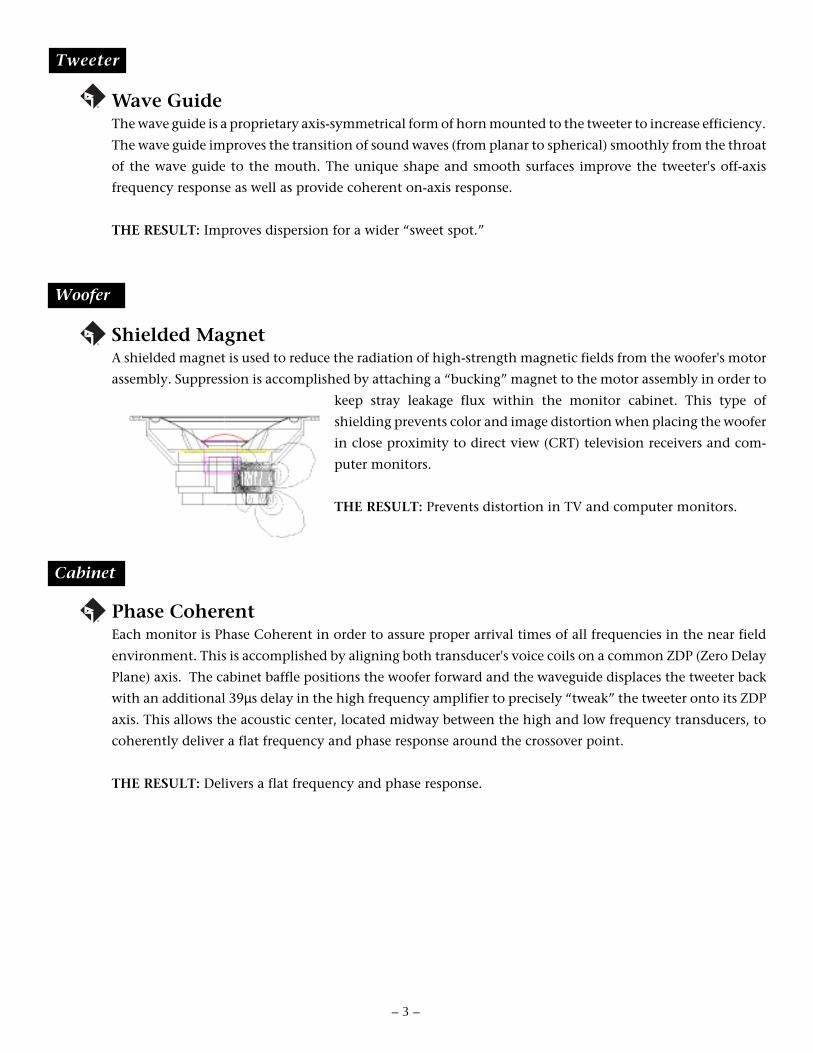
Wave GuideThe wave guide is a proprietary axis-symmetrical form of horn mounted to the tweeter to increase efficiency.
The wave guide improves the transition of sound waves (from planar to spherical) smoothly from the throat
of the wave guide to the mouth. The unique shape and smooth surfaces improve the tweeter's off-axis
frequency response as well as provide coherent on-axis response.
THE RESULT: Improves dispersion for a wider “sweet spot.”
Shielded MagnetA shielded magnet is used to reduce the radiation of high-strength magnetic fields from the woofer's motor
assembly. Suppression is accomplished by attaching a “bucking” magnet to the motor assembly in order to
keep stray leakage flux within the monitor cabinet. This type of
shielding prevents color and image distortion when placing the woofer
in close proximity to direct view (CRT) television receivers and com-
puter monitors.
THE RESULT: Prevents distortion in TV and computer monitors.
Phase CoherentEach monitor is Phase Coherent in order to assure proper arrival times of all frequencies in the near field
environment. This is accomplished by aligning both transducer's voice coils on a common ZDP (Zero Delay
Plane) axis. The cabinet baffle positions the woofer forward and the waveguide displaces the tweeter back
with an additional 39µs delay in the high frequency amplifier to precisely “tweak” the tweeter onto its ZDP
axis. This allows the acoustic center, located midway between the high and low frequency transducers, to
coherently deliver a flat frequency and phase response around the crossover point.
THE RESULT: Delivers a flat frequency and phase response.
®
®
Tweeter
Woofer
Cabinet

ON
1234
ON
1234
ON
1234
ON
1234
A D
ivis
ion
of R
ockf
ord
Cor
p.Te
mpe
, AZ
852
81 U
.S.A
.M
ade
in t
he U
.S.A
.
®
XLR
Con
nect
ions
3
21
+
–
5kH
z20
kHz
Sens
itivi
tydB
U in
put r
equi
red
for
100d
B SP
L@ 1
m
SELE
CT
ON
E
0dB
0dB
30H
z
dB
+4 +2 0 –2 –4
200H
z
+4dB
u
XL
RBa
lanc
ed
Sign
al In
Tran
s•an
a Re
fere
nce
Mon
itor
- TRM
6
250V
T3A
115
V~
60 H
Z
WA
RN
ING
: D
O N
OT
RE
MO
VE
CO
VE
RT
O
RE
DU
CE
T
HE
R
ISK
O
F
FIR
E
OR
E
LE
CT
RIC
S
HO
CK
DO
NO
T E
XP
OS
E T
HIS
EQ
UIP
ME
NT
TO
RA
IN O
R M
OIS
TU
RE
.
!R
ISK
OF
ELE
CT
RIC
SH
OC
KD
O N
OT
OP
EN
+4 +2 0 –2 –4
dB
Bass
She
lvin
gSE
LEC
T O
NE
Treb
le S
helv
ing
SELE
CT
ON
E
RCA
- U
nbal
- +1d
Bu-
-2dB
u-
-5dB
u
- -8
dBu
- -1
1dBu
- 3
0Hz
- 6
0Hz
- +4d
B- +
2dB
- -2
dB-
-4dB
- +4d
B- +
2dB
- -2
dB-
-4dB
Bass
Rol
l Off
SELE
CT
30H
zO
R 60
Hz
30H
z 6
0Hz
140W
Max
CA
UTIO
N
Pow
erSw
itch
Fro
nt
Pa
ne
l V
iew
– 4 –
Re
ar
Pa
ne
l V
iew
Woo
fer
Twee
ter
Rub
ber
Pad
Stat
us L
ED
Wav
e G
uide
Hea
tsin
k
AC
Lin
eIn
put
AC
Lin
eFu
se
Bal
ance
dIn
put
Unb
alan
ced
Inpu
t
Sens
itivi
ty
Bas
s R
oll O
ff
Bas
sSh
elvi
ng
Treb
leSh
elvi
ng
Inpu
t Sw
itch

LOCATIONThe location of your reference monitors in addition to the acoustics of the listening room will influence the systemfrequency response. In the near field environment, our ears are more sensitive to direct sound rather than thereverberation of sound. Below are some recommendations for the initial set-up which may help you optimizeperformance in complex acoustic environments. In any configuration, keep the rear of the monitor at least 5" (12.7cm)away from any wall or obstruction to reduce excessive boundary “loading” of the woofer vent and to optimize heatsink cooling.
I N S T A L L A T I O N
Aiming the monitors directly forward (Fig. 1) may cause response problems resulting in inadequate stereo imaging.Aiming the monitors toward you and spaced equally like a triangle (Fig. 2) provides the best imaging and produces theflattest frequency response.
If you frequently move your chair from side to side in front of your mixing console, positioning the tweeter and wooferin horizontal alignment (Fig. 3) can create complex lobing patterns. Minimizing this effect can be achieved by placingthe tweeter and woofer in vertical alignment (Fig. 4). If it is essential to position the monitors horizontally, place themwith the tweeters toward the inside.
INADEQUATEOff-Axis ResponseFig. 1
OPTIMUMOn-Axis Response
Fig. 2
INADEQUATEHorizontal AlignmentFig. 3
OPTIMUMVertical Alignment
Fig. 4
– 5 –
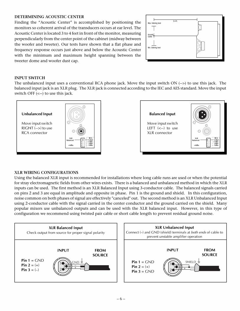
XLR Balanced InputCheck output from source for proper signal polarity
Pin 1 = GNDPin 2 = (+)Pin 3 = (–)
INPUT FROMSOURCE
XLR Unbalanced InputConnect (–) and GND (shield) terminals at both ends of cable to
prevent unstable amplifier operation
Pin 1 = GNDPin 2 = (+)Pin 3 = GND
INPUT FROMSOURCE
1
23
GND–+
1
23
SHIELD
+
INPUT SWITCHThe unbalanced input uses a conventional RCA phone jack. Move the input switch ON (-->) to use this jack. Thebalanced input jack is an XLR plug. The XLR jack is connected according to the IEC and AES standard. Move the inputswitch OFF (<--) to use this jack.
DETERMINING ACOUSTIC CENTERFinding the “Acoustic Center” is accomplished by positioning themonitors so coherent arrival of the transducers occurs at ear level. TheAcoustic Center is located 3 to 4 feet in front of the monitor, measuringperpendicularly from the center point of the cabinet (midway betweenthe woofer and tweeter). Our tests have shown that a flat phase andfrequency response occurs just above and below the Acoustic Centerwith the minimum and maximum height spanning between thetweeter dome and woofer dust cap.
3-4 ft.Max. listening level
AcousticCenter
Min. listening level
– 6 –
XLR WIRING CONFIGURATIONSUsing the balanced XLR input is recommended for installations where long cable runs are used or when the potentialfor stray electromagnetic fields from other wires exists. There is a balanced and unbalanced method in which the XLRinputs can be used. The first method is an XLR Balanced Input using 3-conductor cable. The balanced signals carriedon pins 2 and 3 are equal in amplitude and opposite in phase. Pin 1 is the ground and shield. In this configuration,noise common on both phases of signal are effectively "canceled" out. The second method is an XLR Unbalanced Inputusing 2-conductor cable with the signal carried in the center conductor and the ground carried on the shield. Manypopular mixers use unbalanced outputs and can be used with the XLR balanced input. However, in this type ofconfiguration we recommend using twisted pair cable or short cable length to prevent residual ground noise.
Unbalanced Input
Move input switchRIGHT (-->) to useRCA connector
Balanced Input
Move input switchLEFT (<--) to useXLR connector
+4dBu
XLRBalanced
RCA Unbal- +1dBu- -2dBu- -5dBu
ON
12
34
+4dBu
XLRBalanced
RCA Unbal- +1dBu- -2dBu- -5dBu
ON
12
34

S C H E M A T I C D I A G R A M
NOTES: Unless specified otherwise1. All resistors in ohms.2. All capacitors in microfarads.3. Channel 1 only shown.
– 7 –

! Qualified Service Personnel Only
–8–

Removable Center Spread
S C H E M A T I C D I A G R A M
NOTES: Unless specified otherwise1. All resistors in ohms.2. All capacitors in microfarads.3. Channel 1 only shown.

Removable Center Spread
! Qualified Service Personnel Only

-11-
S C H E M A T I C D I A G R A MN
OTE
S: U
nles
s sp
ecifi
ed o
ther
wis
e1.
All
resi
stor
s in
ohm
s.2.
All
capa
cito
rs in
mic
rofa
rads
.3.
Cha
nnel
1 o
nly
show
n.
!Q
ualif
ied
Serv
ice
Pers
onne
l Onl
y

PC BOARD LAYOUT!
Qua
lifie
d Se
rvic
e Pe
rson
nel O
nly
– 12 –
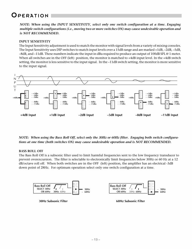
INPUT SENSITIVITYThe Input Sensitivity adjustment is used to match the monitor with signal levels from a variety of mixing consoles.The Input Sensitivity uses DIP switches to match input levels over a 15dB range and are marked +1dB, –2dB, –5dB,–8dB, and –11dB. These numbers indicate the input in dBu required to produce an output of 100dB SPL @ 1 meter.When all switches are in the OFF (left) position, the monitor is matched to +4dB input level. In the +4dB switchsetting, the monitor is less sensitive to the input signal. In the –11dB switch setting, the monitor is more sensitiveto the input signal.
+4dB Input +1dB Input –2dB Input –5dB Input –8dB Input
NOTE: When using the INPUT SENSITIVITY, select only one switch configuration at a time. Engagingmultiple switch configurations (i.e., moving two or more switches ON) may cause undesirable operation andis NOT RECOMMENDED.
INPUT
–11dB Input
– 13 –
OP E R A T I O N
NOTE: When using the Bass Roll Off, select only the 30Hz or 60Hz filter. Engaging both switch configura-tions at one time (both switches ON) may cause undesirable operation and is NOT RECOMMENDED.
BASS ROLL OFFThe Bass Roll Off is a subsonic filter used to limit harmful frequencies sent to the low frequency transducer toprevent overexcursion. The filter is selectable to electronically limit frequencies below 30Hz or 60 Hz at a 12dB/octave roll off. When both switches are in the OFF (left) position, the amplifier has an electrical -3dBdown point of 28Hz. For optimum operation select only one switch configuration at a time.
+4dBu
- +1dBu- -2dBu- -5dBu
- -8dBu- -11dBu
ON
12
34
ON
12
34
+4dBu
- +1dBu- -2dBu- -5dBu
- -8dBu- -11dBu
ON
12
34
ON
12
34
+4dBu
- +1dBu- -2dBu- -5dBu
- -8dBu- -11dBu
ON
12
34
ON
12
34
+4dBu
- +1dBu- -2dBu- -5dBu
- -8dBu- -11dBu
ON
12
34
ON
12
34
+4dBu
- +1dBu- -2dBu- -5dBu
- -8dBu- -11dBu
ON
12
34
ON
12
34
+4dBu
- +1dBu- -2dBu- -5dBu
- -8dBu- -11dBu
ON
12
34
ON
12
34
- 30Hz- 60Hz
Bass Roll OffSELECT 30Hz
OR 60Hz 30Hz 60HzON
12
34
- 30Hz- 60Hz
Bass Roll OffSELECT 30Hz
OR 60Hz 30Hz 60HzON
12
34
30Hz Subsonic Filter 60Hz Subsonic Filter

BASS SHELVINGBass Shelving is used to match the low frequency response of the monitor to the acoustic environment. BassShelving uses DIP switches to control frequencies from 40Hz to 200Hz over an 8dB range and are marked +4dB,+2dB, –2dB, and –4dB. When all switches are in the OFF (left) position, the bass level is at 0dB.
NOTE: When using the BASS SHELVING & TREBLE SHELVING, select only one switch configuration at atime. Engaging multiple switch configurations (i.e., moving two or more switches ON) may cause undesirableoperation and is NOT RECOMMENDED.
TREBLE SHELVINGTreble Shelving uses DIP switches to control frequencies from 5kHz to 20kHz over an 8dB range and are marked+4dB, +2dB, –2dB, and –4dB. When all switches are in the OFF (left) position, the treble level is at 0dB.
40Hz
dB
+4+20
–2–4
200Hz 40Hz
dB
+4+20
–2–4
200Hz 40Hz
dB
+4+20
–2–4
200Hz 40Hz
dB
+4+20
–2–4
200Hz 40Hz
dB
+4+20
–2–4
200Hz
0dB
- +4dB- +2dB- -2dB- -4dB
ON
12
34
0dB
- +4dB- +2dB- -2dB- -4dB
ON
12
34
0dB
- +4dB- +2dB- -2dB- -4dB
ON
12
34
0dB
- +4dB- +2dB- -2dB- -4dB
ON
12
34
0dB
- +4dB- +2dB- -2dB- -4dB
ON
12
34
5kHz
dB
+4+20
–2–4
20kHz 5kHz
dB
+4+20
–2–4
20kHz 5kHz
dB
+4+20
–2–4
20kHz 5kHz
dB
+4+20
–2–4
20kHz 5kHz
dB
+4+20
–2–4
20kHz
0dB
- +4dB- +2dB- -2dB- -4dB
ON
12
34
0dB
- +4dB- +2dB- -2dB- -4dB
ON
12
34
0dB
- +4dB- +2dB- -2dB- -4dB
ON
12
34
0dB
- +4dB- +2dB- -2dB- -4dB
ON
12
34
0dB
- +4dB- +2dB- -2dB- -4dB
ON
12
34
– 14 –
–2dB –4dB+2dB 0dB+4dB
–2dB –4dB+2dB 0dB+4dB
AC LINEThe TRM6 operates from a 115 VAC/60Hz power line. The TRM6 CE operates from a 230 VAC 50/60Hz power line.Connection is made by a 16 gauge, IEC Type 320, grounded line cord. For safety considerations only a properlygrounded (earthed) receptacle should be used. If a grounded circuit is not available, do not break off the ground pin;use the proper adapter plug for a two wire receptacle with the grounding plug suitably connected to earth ground.
IMPORTANT: The power line fuse is mounted on the rear panel. If this fuse blows, replace it onlywith the same type and rating as indicated in the parts list.
!

POWER SWITCHThe POWER switch is located on the front panel. The LED will illuminate GREEN, indicating the respectiveamplifiers are on. It is possible to leave the power switch in the ON position and switch the monitor remotelythrough a power distribution block or switched outlet. When doing so, make sure the switch is rated for the currentrequired by the monitor.
Standard practice is to turn the amplifier on last and off first when switching components to preventsending damaging transients to the speakers.
Es costumbre encender el amplificador de último y apagarlo de primero cuando se estan encendiendo/apagando otros equipos, para así evitar el envío de transientes dañinas a los parlantes.
Il est de pratique courante de commencer par tourner l'amplificateur sur “off” et de terminer par “on,”lorsqu'il s'agit de prévenir l'envoie de passages nuisible aux haut-parleurs.
Der Verstärker sollte als letztes Gerät eingeschaltet und als erstes Gerät wieder ausgeschaltet werden,um eine Beschädigung der Lautsprecher durch spannungsspitzen zu vermeiden.
L'uso comune consiglia l'accensione dell'amplificatore per ultimo e lo spegnimento per primo quandosi accendono i vari componenti, per evitare l'invio di transitori danneggianti agli altoparlanti.
!
!
!
!
!
– 15 –
STATUS LEDAmplifier operation is monitored internally and has a status LED. This indicator can be used for systemtroubleshooting in case of aberrant behavior.
RUBBER PADA large rubber pad is supplied to eliminate annoying buzzes and rattles when placing the monitors on mixingconsoles or similar mounting surfaces. Attach the pad to the underside of the monitor in the following manner:• Thoroughly clean area where pad will be positioned (i.e., with isopropyl alcohol)• Remove paper liner from rubber pad (avoid touching adhesive with fingers)• Position pad in desired location• Press pad firmly to insure good contact
BREAK-IN and WARM-UPWe recommend initially breaking in the woofer for approximately 8 hours with musical information to establishthe monitor's natural bass response. To achieve the best sonic performance and image stability from the internalamplifiers, we recommend letting them warm up for 1 hour before beginning any critical listening.
CLEANING & MAINTENANCEThere is no requirement for regular maintenance on the electronic components of the monitor. If the cabinet orwoofer becomes soiled, it can be cleaned using a damp, soft cloth. If the monitor is located in a particularly dustyenvironment, cleaning the inside with compressed air or vacuuming every 18 to 24 months is sufficient.
LED – Monitors the status of the amplifiers.
*Indicates the amplifier is on regardless of input signal
COLOR STATUS
GREEN Power on*
FLASHING RED Clipping
RED Thermal

– 16 –
P A R T S L I S TDESIGNATOR VALUE PART #ALL RESISTORS IN OHMS
R1 RES 1.0K OHM 1/10W 1% RM/10-1001BR10 RES 47K OHM 1/10W 5% RM/10-473BR102 RES 6.8K OHM 1/4W 5% RM/4-682CR103 RES 6.8K OHM 1/4W 5% RM/4-682CR104 POT 5K 10% PIHER RV-502QR105 RES 1.0K OHM 1/10W 1% RM/10-1001BR106 35.7K OHM 1/10 WATT 1% RM/10-3572BR107 35.7K OHM 1/10 WATT 1% RM/10-3572BR108 35.7K OHM 1/10 WATT 1% RM/10-3572BR109 RES 14K OHM 1/10W 1% RM/10-1402BR11 POT 2K TRIM RV-202R110 RES 14K OHM 1/10W 1% RM/10-1402BR111 RES 14K OHM 1/10W 1% RM/10-1402BR112 RES 13K OHM 1/10W 5% RM/10-133BR113 RES 300 OHM 1/10W 5% RM/10-301BR114 RES 620 OHM 1/10W 5% RM/10-621BR115 RES 10 OHM 1/10W 5% RM/10-100BR116 RES 620 OHM 1/10W 5% RM/10-621BR117 RES 100 OHM 1/4W 5% RM/4-101CR118 RES 2.0K OHM 1/10W 1% RM/10-2001BR119 RES 1.0K OHM 1/10W 1% RM/10-1001BR12 RES 10K OHM 1/10W 5% RM/10-103BR120 RES 9.76K OHM 1/10W 1% RM/10-9761BR121 RES 280 OHM 1/10W 1% RM/10-2800BR122 RES 10 OHM 1/10W 5% RM/10-100BR123 RES 100 OHM 1/4W 5% RM/4-101CR124 RES 510 OHM 1/10W 5% RM/10-511BR125 RES 510 OHM 1/10W 5% RM/10-511BR128 RES 7.15K OHM 1/10W 1% RM/10-7151BR129 RES 7.15K OHM 1/10W 1% RM/10-7151BR13 RES 47K OHM 1/10W 5% RM/10-473BR130 RES 976K OHM 1/10W 1% RM/10-9763BR131 RES 20.0K OHM 1/10W 1% RM/10-2002BR132 RES 20 OHM 1/10W 5% RM/10-200BR133 RES 2.0K OHM 1/10W 1% RM/10-2001BR134 RES 20.0K OHM 1/10W 1% RM/10-2002BR135 RES 22K OHM 1/10W 5% RM/10-223BR136 POT 5K 10% RV-502QR137 RES 1.0K OHM 1/10W 1% RM/10-1001BR138 RES 20 OHM 1/10W 5% RM/10-200BR139 RES 20 OHM 1/10W 5% RM/10-200BR14 RES 10K OHM 1/10W 5% RM/10-103BR140 RES 2.0K OHM 1/10W 1% RM/10-2001BR141 RES 20 OHM 1/10W 5% RM/10-200BR142 RES 10 OHM 1W RM1-100-012R143 RES 1.0K OHM 1/10W 1% RM/10-1001BR144 RES 1.07K OHM 1/10W 1% RM/10-1071BR145 RES 3.92K OHM 1/4W 1% RMP/4-3921-03R146 RES 2.2M OHM 1/10W 5% RM/10-225BR147 RES 3.92K OHM 1/4W 1% RM/4-3921CR148 RES 1.0K OHM 1/10W 1% RM/10-1001BR15 RES 3.3M OHM 1/10W 5% RM/10-335BR150 RES 100 OHM 1/10W 5% RM/10-101BR151 RES 100 OHM 1/10W 5% RM/10-101BR154 RES 1.5K OHM 1/10W 5% RM/10-152BR156 RES 1.0K OHM 1/10W 1% RM/10-1001BR16 RES 4.7K OHM 1/10W 5% RM/10-472BR163 RES 16.2K 1/10 1% RM/10-1622BR164 RES 191K OHM 1/10W 1% RM/10-1913BR165 RES 0 OHM 1/10W RM/10-000BR166 RES 9.09KOHM 1/10W 1% RM/10-9091BR167 RES 6.49K OHM 1/10W 1% RM/10-6491BR169 RES 2.0K OHM 1/10W 1% RM/10-2001BR17 RES 10K OHM 1/10W 5% RM/10-103BR170 RES 9.76K OHM 1/10W 1% RM/10-9761BR171 RES 2.0K OHM 1/10W 1% RM/10-2001BR172 RES 2.0K OHM 1/10W 1% RM/10-2001BR173 RES 2.21K OHM 1/10W 1% RM/10-2211BR174 RES 1.33K OHM 1/4W 1% RM/4-1331C
R175 35.7K OHM 1/10 WATT 1% RM/10-3572BR176 RES 909 OHM 1/10W 1% RM/10-9090BR177 35.7K OHM 1/10 WATT 1% RM/10-3572BR178 30.1K RES 1% 0805 RM/10-3012BR179 RES 2.0K OHM 1/10W 1% RM/10-2001BR18 RES 100K OHM 1/10W 5% RM/10-104BR180 RES 20 OHM 1/10W 5% RM/10-200BR181 RES 20 OHM 1/10W 5% RM/10-200BR182 RES 20 OHM 1/10W 5% RM/10-200BR183 RES 20 OHM 1/10W 5% RM/10-200BR184 RES 10 OHM 1W RM1-100-012R19 RES 604K OHM 1/10W 1% RM/10-6043BR2 RES 1.0K OHM 1/10W 1% RM/10-1001BR20 RES 100K OHM 1/10W 5% RM/10-104BR21 RES 2.2M OHM 1/10W 5% RM/10-225BR22 RES 100K OHM 1/10W 5% RM/10-104BR23 RES 100K OHM 1/10W 5% RM/10-104BR24 RES 10K OHM 1/10W 5% RM/10-103BR25 RES 2.0K OHM 1/10W 1% RM/10-2001BR26 RES 1M OHM 1/10W 5% RM/10-105BR27 RES 1.3K OHM 1/10W 5% RM/10-132BR278 RES 510 OHM 1/10W 5% RM/10-511BR279 RES 510 OHM 1/10W 5% RM/10-511BR28 RES 1.3K OHM 1/10W 5% RM/10-132BR29 RES 121 OHM 1/4W 1% RM/4-1210CR3 RES 1.0K OHM 1/10W 1% RM/10-1001BR30 RES 121 OHM 1/4W 1% RM/4-1210CR31 RES 220 OHM 1/10W 5% RM/10-221BR32 RES 10 OHM 1/10W 5% RM/10-100BR33 RES 300 OHM 1/10W 5% RM/10-301BR34 RES 300 OHM 1/10W 5% RM/10-301BR35 RES 2.0K OHM 1/10W 1% RM/10-2001BR36 RES 3.3M OHM 1/10W 5% RM/10-335BR37 RES 10 OHM 1/10W 5% RM/10-100BR38 RES 300 OHM 1/10W 5% RM/10-301BR39 RES 300 OHM 1/10W 5% RM/10-301BR4 RES 47K OHM 1/10W 5% RM/10-473BR40 RES 2.0K OHM 1/10W 1% RM/10-2001BR41 RES 620 OHM 1/10W 5% RM/10-621BR42 RES 300 OHM 1/10W 5% RM/10-301BR43 RES 1.0K OHM 1/10W 1% RM/10-1001BR44 24.9K OHM RES. 1/10 W 1% RM/10-2492BR45 RES 1.0K OHM 1/10W 1% RM/10-1001BR46 RES 3.92K OHM 1/4W 1% RMP/4-3921-03R47 RES 2.2M OHM 1/10W 5% RM/10-225BR48 RES 3.92K OHM 1/4W 1% RM/4-3921CR49 RES 604K OHM 1/10W 1% RM/10-6043BR5 RES 1.0K OHM 1/10W 1% RM/10-1001BR50 RES 4.7K OHM 1/10W 5% RM/10-472BR51 RES 15K OHM 1/10W 5% RM/10-153BR52 RES 1.0K OHM 1/10W 1% RM/10-1001BR53 RES 2.2M OHM 1/10W 5% RM/10-225BR54 RES 300 OHM 1/10W 5% RM/10-301BR55 RES 100 OHM 1/10W 5% RM/10-101BR56 RES 15K OHM 1/10W 5% RM/10-153BR57 RES 10K OHM 1/10W 5% RM/10-103BR58 200 TRIM POT RVH-201R59 35.7K OHM 1/10 WATT 1% RM/10-3572BR6 RES 1.0K OHM 1/10W 1% RM/10-1001BR60 RES 100 OHM 1/10W 5% RM/10-101BR61 RES 10K OHM 1/10W 5% RM/10-103BR62 RES 2.2M OHM 1/10W 5% RM/10-225BR63 RES 470 OHM 1/10W 5% RM/10-471BR64 RES 300 OHM 1/10W 5% RM/10-301BR65 RES 1.5K OHM 1/10W 5% RM/10-152BR66 RES 620 OHM 1/10W 5% RM/10-621BR67 RES 1.0K OHM 1/10W 1% RM/10-1001BR68 RES 100 OHM 1/4W 5% RM/4-101CR69 RES 2.0K OHM 1/10W 1% RM/10-2001BR7 RES 1.0K OHM 1/10W 1% RM/10-1001BR70 RES 280 OHM 1/10W 1% RM/10-2800BR71 RES 10 OHM 1/10W 5% RM/10-100B

– 17 –
R72 RES 100 OHM 1/4W 5% RM/4-101CR73 RES 2.21K OHM 1/10W 1% RM/10-2211BR74 RES 2.21K OHM 1/10W 1% RM/10-2211BR75 RES 100K OHM 1/10W 5% RM/10-104BR76 619K OHM 1/10W 1% RM/10-6193BR78 RES 1M OHM 1/10W 5% RM/10-105BR79 RES 1M OHM 1/10W 5% RM/10-105BR8 POT 2K TRIM RV-202R80 RES 6.49K OHM 1/10W 1% RM/10-6491BR81 RES 6.49K OHM 1/10W 1% RM/10-6491BR82 46.4K OHM RES. 1/10 W 1% RM/10-4642BR84 RES 120 OHM 1/10W 5% RM/10-121BR85 46.4K OHM RES. 1/10 W 1% RM/10-4642BR86 RES 5.49K OHM 1/10W 1% RM/10-5491BR87 RES 1.62K OHM 1/4W 1% RM/4-1621CR88 RES 2.0K OHM 1/10W 1% RM/10-2001BR89 RES 2.21K OHM 1/10W 1% RM/10-2211BR9 POT 2K TRIM RV-202R90 RES 2.21K OHM 1/10W 1% RM/10-2211BR91 RES 9.09KOHM 1/10W 1% RM/10-9091BR92 RES 9.09KOHM 1/10W 1% RM/10-9091BR93 RES 3.32K OHM 1/10W 1% RM/10-3321BR94 RES 2.0K OHM 1/10W 1% RM/10-2001BR95 RES 3.24K OHM 1/10W 1% RM/10-3241BR96 RES 1.62K OHM 1/4W 1% RM/4-1621CR97 RES 1.33K OHM 1/4W 1% RM/4-1331CR98 24.9K OHM RES. 1/10 W 1% RM/10-2492BR99 RES 1.0K OHM 1/10W 1% RM/10-1001B
C1 CAP 220PF 50V 5% CDS-221CAAAC10 CAP 47PF 50V 5% CDS-470CAAAC11 CAP 10UF 16V CER-106SMC12 CAP 3300UF 35V CERS-338BC14 CAP .47UF 50V CYV-474-033C15 CAP .1UF 50V CYV-104-033C16 CAP 3300UF 35V CERS-338BC17 CAP .1UF 50V 10% CDS-104CBBBC18 CAP .1UF 50V 10% CDS-104CBBBC19 CAP .1UF 50V 10% CDS-104CBBBC2 CAP 220PF 50V 5% CDS-221CAAAC20 CAP .1UF 50V 10% CDS-104CBBBC202 CAP 100PF 50V 5% CDS-101CAAAC21 CAP 47PF 50V 5% CDS-470CAAAC22 CAP .47UF 50V CYV-474-033C23 CAP .47UF 50V CYV-474-033C24 CAP .1UF 50V 10% CDS-104CBBBC25 CAP .1UF 50V 10% CDS-104CBBBC26 CAP .1UF 50V CYV-104-033C27 CAP .1UF 50V 10% CDS-104CBBBC28 CAP 2.2UF 50V CER-225CSMC29 CAP 10UF 16V CER-106SMC3 CAP .1UF 50V 10% CDS-104CBBBC30 CAP .1UF 50V 10% CDS-104CBBBC31 CAP .1UF 50V 10% CDS-104CBBBC32 CAP 10UF 16V CER-106SMC34 CAP .1UF 50V CYV-104-033C35 CAP 100PF 50V 5% CDS-101CAAAC36 CAP .0022UF 50V CYV-222-033C38 CAP 47PF 50V 5% CDS-470CAAAC39 CAP 47PF 50V 5% CDS-470CAAAC4 CAP .1UF 50V 10% CDS-104CBBBC40 CAP .001UF 50V CYV-102-033C41 CAP .001UF 50V CYV-102-033C42 CAP .001UF 50V CYV-102-033C43 CAP .001UF 50V CYV-102-033C44 CAP 220PF 50V 5% CDS-221CAAAC45 CAP .01UF 50V CYV-103-033C46 CAP .01UF 50V CYV-103-033C47 CAP .001UF 50V CYV-102-033C48 CAP .001UF 50V CYV-102-033C49 CAP 220PF 50V 5% CDS-221CAAAC5 .047UF 50V CYV-473-033C50 CAP .001UF CDS-102CBAAC51 .047UF 50V CYV-473-033C52 CAP 120PF CDS-121CAAA
C53 CAP .1UF 50V CYV-104-033C54 CAP 47PF 50V 5% CDS-470CAAAC55 CAP .001UF 50V CYV-102-033C56 CAP .001UF 50V CYV-102-033C57 CAP .1UF 50V 10% CDS-104CBBBC58 CAP .1UF 50V 10% CDS-104CBBBC59 CAP 47PF 50V 5% CDS-470CAAAC6 CAP 220PF 50V 5% CDS-221CAAAC60 CAP .001UF 50V CYV-102-033C61 CAP .001UF 50V CYV-102-033C62 CAP-022UF 50V CYV-223-033C63 CAP-022UF 50V CYV-223-033C64 CAP .0022UF 50V CYV-222-033C65 CAP 220PF 50V 5% CDS-221CAAAC66 CAP 120PF 50V 5% CDS-121CAAAC67 CAP .1UF 50V CYV-104-033C69 CAP 47PF 50V 5% CDS-470CAAAC7 CAP 220PF 50V 5% CDS-221CAAAC70 CAP 10UF 16V CER-106SMC71 CAP 3300UF 35V CERS-338BC72 CAP 3300UF 35V CERS-338BC75 CAP 47PF 50V 5% CDS-470CAAAC76 CAP .47UF 50V CYV-474-033C80 CAP .1UF 50V 10% CDS-104CBBBC81 CAP .1UF 50V 10% CDS-104CBBBC82 CAP .1UF 50V 10% CDS-104CBBBC83 CAP 47PF 50V 5% CDS-470CAAAC84 CAP .1UF 50V 10% CDS-104CBBBC85 CAP .1UF 50V CYV-104-033C86 CAP 220PF 50V 5% CDS-221CAAAC87 CAP 120PF 50V 5% CDS-121CAAAC88 CAP 120PF 50V 5% CDS-121CAAAC9 CAP .1UF 50V 10% CDS-104CBBB
CR1 DIO DUAL BAV99L SS-260SMCR10 BRIDGE RECTIFIER SS-0799-068CR11 DIO DUAL BAV99L SS-260SMCR13 DIO MMBD914L SS-803SMCR14 DIO ZENER MMBZ5240BL SS-1052CR15 DIO DUAL BAV99L SS-260SMCR16 DIO DUAL BAV99L SS-260SMCR2 DIO DUAL BAV99L SS-260SMCR22 DIO MMBD914L SS-803SMCR3 RD/GRN BICOLOR LED SS-2423CR4 DIO DUAL BAV99L SS-260SMCR5 DIO MMBD914L SS-803SMCR6 DIO MMBD914L SS-803SMCR7 DIO MMBD914L SS-803SMCR8 DIO MMBD914L SS-803SMCR9 DIO DUAL BAV99L SS-260SM
Q10 XSTR MMBT3906LT1 PNP SS-0791Q11 XSTR MMBT5088L NPN SS-0114Q12 XSTR MMBT5088L NPN SS-0114Q13 XSTR MPS-A56 SS-101A-45Q14 XSTR MMBT5088L NPN SS-0114Q15 XSTR NPN MPSA06 SS-102A-45Q16 XSTR MMBT5088L NPN SS-0114Q17 XSTR MMBT5088L NPN SS-0114Q18 XSTR MMBT5087L PNP SS-0115Q19 XSTR MMBT3906LT1 PNP SS-0791Q2 Regulator LM317 SS-1375Q21 XSTR MMBTA06L SS-102SMQ22 XSTR MPS-A56R SS-101A-45Q23 XSTR NPN MPSA06 SS-102A-45Q24 XSTR MMBT3904LT1 NPN SS-0792Q25 XSTR MMBT5088L NPN SS-0114Q26 XSTR MMBT5087L PNP SS-0115Q27 XSTR MMBT5088L NPN SS-0114Q28 XSTR MMBT5088L NPN SS-0114Q29 XSTR MPS6521 SS-209Q3 Regulator LM337 SS-1376Q30 XSTR MMBT5088L NPN SS-0114Q31 XSTR MMBT5088L NPN SS-0114Q32 XSTR MMBT3906LT1 PNP SS-0791
!
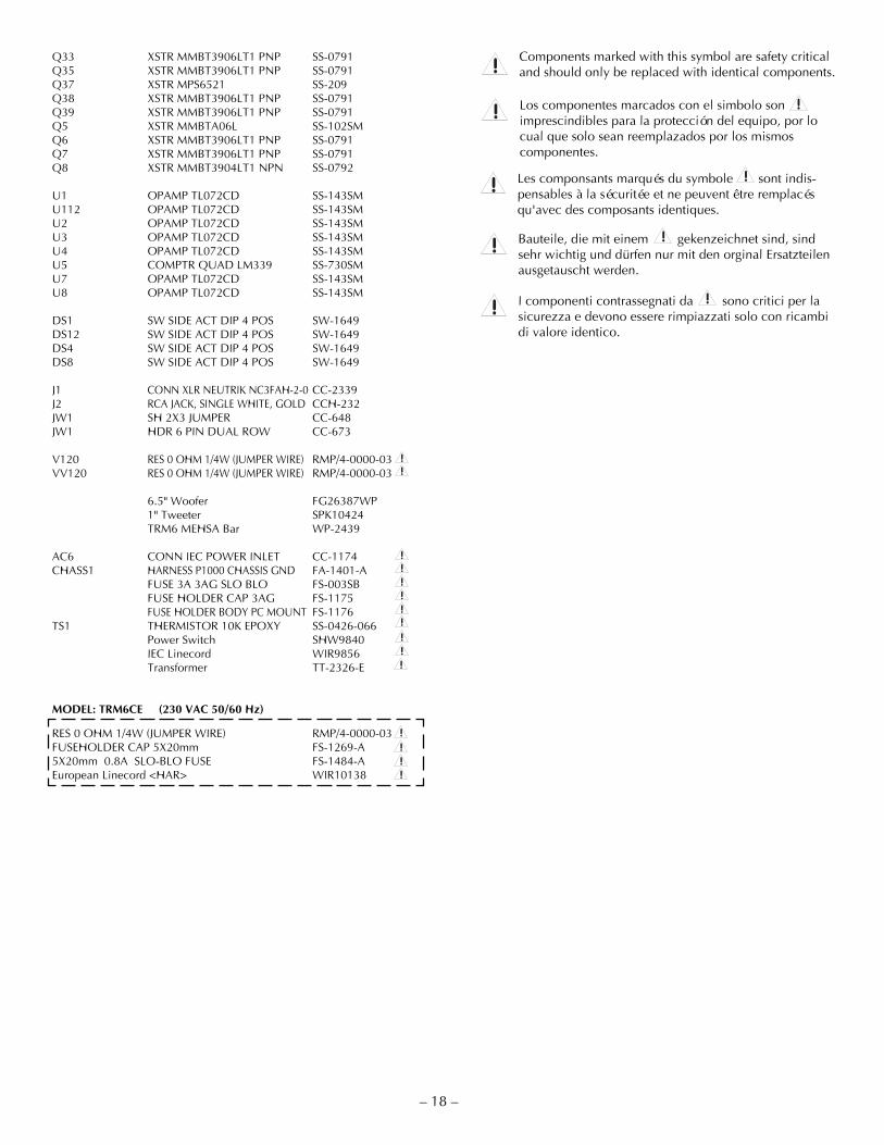
! Components marked with this symbol are safety criticaland should only be replaced with identical components.
! Los componentes marcados con el simbolo sonimprescindibles para la protección del equipo, por locual que solo sean reemplazados por los mismoscomponentes.
!
! Les componsants marqués du symbole sont indis-pensables à la sécuritée et ne peuvent être remplacésqu'avec des composants identiques.
!
! Bauteile, die mit einem gekenzeichnet sind, sindsehr wichtig und dürfen nur mit den orginal Ersatzteilenausgetauscht werden.
!
! I componenti contrassegnati da sono critici per lasicurezza e devono essere rimpiazzati solo con ricambidi valore identico.
!
– 18 –
Q33 XSTR MMBT3906LT1 PNP SS-0791Q35 XSTR MMBT3906LT1 PNP SS-0791Q37 XSTR MPS6521 SS-209Q38 XSTR MMBT3906LT1 PNP SS-0791Q39 XSTR MMBT3906LT1 PNP SS-0791Q5 XSTR MMBTA06L SS-102SMQ6 XSTR MMBT3906LT1 PNP SS-0791Q7 XSTR MMBT3906LT1 PNP SS-0791Q8 XSTR MMBT3904LT1 NPN SS-0792
U1 OPAMP TL072CD SS-143SMU112 OPAMP TL072CD SS-143SMU2 OPAMP TL072CD SS-143SMU3 OPAMP TL072CD SS-143SMU4 OPAMP TL072CD SS-143SMU5 COMPTR QUAD LM339 SS-730SMU7 OPAMP TL072CD SS-143SMU8 OPAMP TL072CD SS-143SM
DS1 SW SIDE ACT DIP 4 POS SW-1649DS12 SW SIDE ACT DIP 4 POS SW-1649DS4 SW SIDE ACT DIP 4 POS SW-1649DS8 SW SIDE ACT DIP 4 POS SW-1649
J1 CONN XLR NEUTRIK NC3FAH-2-0 CC-2339J2 RCA JACK, SINGLE WHITE, GOLD CCH-232JW1 SH 2X3 JUMPER CC-648JW1 HDR 6 PIN DUAL ROW CC-673
V120 RES 0 OHM 1/4W (JUMPER WIRE) RMP/4-0000-03VV120 RES 0 OHM 1/4W (JUMPER WIRE) RMP/4-0000-03
6.5" Woofer FG26387WP1" Tweeter SPK10424TRM6 MEHSA Bar WP-2439
AC6 CONN IEC POWER INLET CC-1174CHASS1 HARNESS P1000 CHASSIS GND FA-1401-A
FUSE 3A 3AG SLO BLO FS-003SBFUSE HOLDER CAP 3AG FS-1175FUSE HOLDER BODY PC MOUNT FS-1176
TS1 THERMISTOR 10K EPOXY SS-0426-066Power Switch SHW9840IEC Linecord WIR9856Transformer TT-2326-E
MODEL: TRM6CE (230 VAC 50/60 Hz)
RES 0 OHM 1/4W (JUMPER WIRE) RMP/4-0000-03FUSEHOLDER CAP 5X20mm FS-1269-A5X20mm 0.8A SLO-BLO FUSE FS-1484-AEuropean Linecord <HAR> WIR10138
!!
!!!!!!!!!
!!!!

TRM6 FUNCTIONAL BLOCK DIAGRAM
– 19 –
V+
OutputQ20
OutputQ4
V–
DriverQ30, Q32
+15VRegulator
Q2
DriverQ31, Q33
-15VRegulator
Q3
Pre-DriverQ25
BiasAdjust
R11, Q29
Pre-DriverQ26
DriverSignal
Q23, Q22
CurrentSourceQ21
Protection SwitchSoft Start DelayQ24, C70, R13
Differential AmpQ27, Q28
CMRRAdjustR58
PositiveInput Buffer
U8A
Current MirrorQ10, Q19
FeedbackNetworks
DC OffsetIntegrator
U8B, C76, R146
NegativeInput Buffer
U1B
LocalFeedback
C51, R142
Output

CIRCUIT OPERATION
trans•ana ImplementationThe transistor Q24 is configured to operate as a switch that controls the constant current source Q21 of the differentialamplifier Q27 and Q28. Switch Q24 is under the control of the thermal and turn-on circuits, and provides a Soft Startturn-on ramp according to the charging time of C70 through R13 and R156.
U8B is configured as a DC servo-integrator to null the output offset voltage. Class AB bias current is established by Q29,and adjusted by R11.
The positive and negative input signals are conveyed to the pre-driver transistors Q25 and Q26 by the differentialamplifier Q27 and Q28, and by current mirror Q10 and Q19. Drivers Q22 and Q23 make the transition from the low-voltage front-end circuit to the high-voltage output stage. Buffer transistors Q30 and Q32 enhance the front-end drivecurrent, and drive the positive output MOSFET Q20. The same is true for buffer transistors Q31 and Q33 and negativeoutput MOSFET Q4.
CALIBRATION
WARNING: Only a competent technician should attempt the following procedure.
Bias:The bias control establishes the quiescent Class AB output current of the amplifier. The bias should not needreadjustment from the factory setting: however, if the amplifier is repaired and the output devices have been changed,calibrating the bias is necessary. Disconnect the power to the amplifier before removing the heatsink assembly fromthe speaker cabinet. To adjust the bias, remove the jumper JW1 and connect an ammeter across the exposed pins. Adjusttrimpots R11 and R9 fully counter-clockwise before reapplying power to the unit. After the Soft Start turn-on has settled,note the ammeter reading. Adjust R11 until an additional 50mA is created. Then adjust R9 until another 50mA is addedto the ammeter reading. Replace jumper JW1.
– 20–
S E R V I C E R E F E R E N C E
! Qualified Service Personnel Only

Input Circuit
The input signal is connected to the amplifierthrough the balanced XLR connector J1, or theunbalanced RCA connector J2. Balanced/unbal-anced switch DS1 will ground the inverting inputbuffer, allowing operation with an unbalancedsignal on either connector. Input buffers U1A andU1B provide a stable input impedance, dominatedby R10 and R4. The input circuit gain is set byswitches DS2-DS6. Each switch inserts a differentdivider resistor for the feedback resistors R88 andR169, resulting in up to 15dB of additional inputgain when DS6 is closed. Trimpot R8 adjusts thecommon-mode-rejection of the woofer channel.
The non-inverting input signal from U1A pin 1, andthe inverting input signal from U1B pin 7, aresummed together to form an unbalanced signal atU4A pin 1.
Tweeter Crossover
The balanced input signal at U1A pin 1 and U1B pin 7 connects to a 2-stage 39µs delay, using U3A and U3B. Thisis followed by the high-frequency shelf circuit at U7B. Switches DS13-DS16 add various reactive components to thefeedback network of U7B, resulting in +4dB, +2dB, –2dB, or –4dB of gain shelving above 5kHz. The next stage at U7Ais a 3.2kHz 2nd order high-pass filter. The last stage consists of another 3.2kHz 2nd order high-pass filter, bringing theoverall tweeter crossover response to a 4th order 24dB/octave slope. The final components before the tweeter amplifier(R104 and R105 ) can provide up to 2dB of additional gain to the tweeter channel.
– 21 –
SensitivityAdjust
DS2 - DS6
Non-InvertingInput BufferU1A, R88
InputConnector
J1J2
DS1R10R4
Inverting InputBuffer
U1B, R169
SummingAmplifier
R109, R110,R111, R112, R8
BalancedInput SignalU1A, U1B
2nd Order HP3200Hz
U8AR107, R177
R106, C40, C41
Sensitivity AdjustR104, R105
2nd Order HP3200Hz
U7A
High FrequencyShelf U7B
DS13 - DS16
43µsDelay
U3B, U3A
! Qualified Service Personnel Only

Woofer Crossover
The input signal at U4A pin 1 connects to the 3200Hz 2nd order low-pass filter at U112B. Approximately 2dB ofadditional gain can be added to this stage by adjusting R136 against the divider resistor, R137. The next stage is a30Hz-60Hz switchable sub-sonic high-pass filter. This is followed by an adjustable low-frequency shelving filter whichdefaults at +6dB gain, according to the feedback resistors R129 and R134, and dividers R131 and R128. DS9-DS12 willswitch in various reactive feedback networks to accomplish +4dB, +2dB, –2dB, or –4dB of gain shelving below 200Hz.The last stage is another 3200Hz 2nd order low-pass filter at U2A, which cascades with the previous filter at U112Bto produce an overall 4th order slope of 24dB/octave for the woofer amplifier.
TempTS1, R25
ComparatorU5B
Soft Start SwitchesQ8, Q24
CLIP/THERMALIndicator
CR3
Thermal Protection
The thermal protection is activated, and shuts down audio operation, when the amplifier heatsink reaches anexcessively high temperature. The voltage divider R22 and R23 establishes the reference voltage on pin 5 of U5B. Thecontrol voltage on pin 4 is established by the voltage divider TS1 and R25. TS1 is a NTC (Negative TemperatureCoefficient) thermistor mounted on the heatsink. As TS1 warms and the resistance falls, the voltage on pin 4 rises. Whenthe voltage on pin 4 exceeds the voltage on pin 5, the output on pin 2 goes low, shutting down the Soft Start switchesQ8 and Q24, and lighting the CLIP/THERMAL indicator red.
– 22 –
! Qualified Service Personnel Only
UnbalancedInput Signal
U4A
Low FrequencyShelf
U112ADS9 - DS12,
C85
2nd Order LP3200Hz
U112B, R85,R98, C64, C48
Sensitivity TrimR136, R137
2nd Order HP30Hz-60HzU112A, R49,R76, R164,
R130, C45, C46,DS7, DS8
2nd Order LP3200Hz
U2A, R82, R44,C36, C42

– 23 –
Clipping Indicator
The CLIP indicators are driven by the comparator U5A and U5D. The voltage divider R56, R57, and R51, R61establishes the reference voltage for the Clipping detector at pin 7 of U5A and pin 9 of U5D. Excessive drive signal atpin 6 or pin 8 will trigger its comparator low and light the CLIP/THERMAL indicator red.
On Indicator
The bicolor LED, CR3, will remain green unless a THERMAL or CLIP condition is detected. The outputs of comparatorsU5A and U5D will be high, and Q35 will be off, allowing current to flow through the green LED of CR3 from groundto –17V.
! Qualified Service Personnel Only
CLIP/THERMALIndicator
CR3
ClippingDetectorsU5A, U5D
DriveSignals
DR,DRTWT
ONIndicator
CR3LED DriverQ35, Q36
ClippingDetector
U5A, U5D

– 24 –
TWEETER REPLACEMENT
! Qualified Service Personnel Only
1. Remove (4) screws from wave guide using a 3/32" Allen Wrench2. Remove wave guide assembly from enclosure3. Disconnect the LED harness (FIG. 1)4. Disconnect the (2) speaker wires from the tweeter (FIG. 2)5. Disconnect the (2) power switch wires (FIG. 3)6. Unclip the tweeter from wave guide (4 catch fingers)7. Position the replacement tweeter into wave guide8. Snap the tweeter into wave guide9. Follow steps 1-5 in reverse order to install wave guide assembly
CAUTION: Reconnect wires as indicated in each diagram! Wave Guide Assembly
FIG. 1LED Harness
FIG. 2Tweeter Replacement #SPK10424
FIG. 3Power Switch
!
WOOFER REPLACEMENT
FIG. 4Woofer Replacement
!
1. Remove (4) screws from woofer using a 3/32" Allen Wrench2. Remove woofer from enclosure3. Disconnect (2) speaker wires (FIG. 4)4. Follow steps 1-3 in reverse order to install new woofer
CAUTION: Reconnect wires as indicated in each diagram!

AMPLIFIER REPLACEMENT
– 25 –
! Qualified Service Personnel Only
1. Remove (2) screws from back using a 3/32" Allen Wrench (FIG. 5)2. Disconnect PCB mounted LED harness (FIG. 6)3. Disconnect PCB mounted tweeter speaker wires (FIG. 7)4. Disconnect PCB mounted woofer speaker wires (FIG. 7)5. Disconnect PCB mounted transformer primary wires (FIG. 8)6. Disconnect PCB mounted transformer secondary wires (FIG. 8)7. Disconnect PCB mounted power switch wires (FIG. 8)
CAUTION: Reconnect wires as indicated in diagram!
FIG. 5Amplifier Replacement
ON
12
34
ON
12
34
ON
12
34
ON
12
34
A Division of Rockford Corp.Tempe, AZ 85281 U.S.A.Made in the U.S.A.
®
XLR Connections
3
21+
–
5kHz 20kHz
SensitivitydBU input required for 100dB SPL@ 1m
SELECT ONE
0dB
0dB30Hz
dB
+4+20
–2–4
200Hz
+4dBu
XLRBalanced
Signal InTrans•ana Reference Monitor - TRM6
250V T3A
115 V~60 HZ
WARNING: DO NOT REMOVE COVERTO REDUCE THE RISK OF FIRE OR ELECTRIC SHOCKDO NOT EXPOSE THIS EQUIPMENT TO RAIN OR MOISTURE.
!RISK OF ELECTRIC SHOCKDO NOT OPEN
+4+20
–2–4
dB
Bass ShelvingSELECT ONE
Treble ShelvingSELECT ONE
RCA- Unbal- +1dBu- -2dBu- -5dBu
- -8dBu- -11dBu- 30Hz- 60Hz
- +4dB- +2dB- -2dB- -4dB
- +4dB- +2dB- -2dB- -4dB
Bass Roll OffSELECT 30Hz
OR 60Hz 30Hz 60Hz
140WMax
CAUTION
Removeonlythese
(2) screws
FIG. 6PCB Mounted LED Harness
FIG. 7PCB Mounted Speaker Wires
!
FIG. 8Transformer / Power Switch Wires
TRANSFORMER REPLACEMENT
MODEL TRM6120V 50Hz VAC
MODEL TRM6CE230V 50/60Hz VAC
BLK
WHT
BRN
GRY
PC BOARDBLK
WHT BRNGRY
120VTransformer
PowerSwitch
BR
N
BLK
BLK
WHT
BRN
GRY
PC BOARDBLK
WHT BRNGRY
230VTransformer
PowerSwitch
BR
N
BLK
The TRM6 is available both 120V and 230Vversions. If it is necessary to perform service onthe amplifier, be sure to check connections tothe transformer before re-applying power and/or re-assembling the unit.
CAUTION: Reconnect wires as indicated in diagram!
!

SE R V I C E PO L I C Y A N D LI M I T E D WA R R A N T Y
– 26 –
Rockford Corporation (Hafler Division) offers a limited warranty on Hafler products on the following terms:
• Length of Warranty1 year on Reference Monitors
• What is CoveredThis warranty applies only to products sold to the original owner and is non-transferable. This warranty only appliesto units sold in the continental United States. You are required to have a copy of the receipt stating the customer's name,dealer name, product purchased and date of purchase.
• Products found to be defective during the warranty period will be repaired or replaced (with product deemed to beequivalent) at Hafler's discretion.
• What is NOT Covered1. Damage caused by accident, abuse, improper operations, water, theft2. Service performed by anyone other than Hafler or an Authorized Hafler service center3. Any product purchased outside the United States (please contact your local dealer)4. Shipping charges to get the unit to Hafler5. Any product which has had the serial number defaced, altered, or removed
• Limit on Implied WarrantiesAny implied warranties including warranties of fitness for use and merchantability are limited in duration to the periodof the express warranty set forth above. Some states do not allow limitations on the length of an implied warranty, sothis limitation may not apply. No person is authorized to assume for Hafler any other liability in connection with thesale of the product.
• How to obtain service or technical supportPlease call 1-800-669-9899 for Rockford/Hafler support. You must obtain an RA # (return authorization number) toreturn any products to Hafler. You are responsible for shipment of product to Hafler.
Rockford CorporationHafler Division2055 E. 5th StreetTempe, Arizona 85281

LIT 104273/99 E.W.R.
®
HAFLER
A DIVISION OF
ROCKFORD CORPORATION
546 SOUTH ROCKFORD DRIVE
TEMPE, ARIZONA 85281 U.S.A.
602-967-3565 / 1-888-HAFLER1
WWW.HAFLER.COM
MADE IN THE USAThis product is designed, developed and assembled in the USA by a dedicated
group of American workers. The majority of the components used in theconstruction of this product are produced by American companies. However, due
to the global nature of their manufacturing facilities and the electronics partsindustry in general, some parts may be manufactured in other countries.