H55 Extreme3 UM - download.asrock.com Extreme3.pdf · 7 Audio - 7.1 CH HD Audio with Content...
59
1 H55 Extreme3 User Manual Version 1.0 Published February 2010 Copyright©2010 ASRock INC. All rights reserved.
Transcript of H55 Extreme3 UM - download.asrock.com Extreme3.pdf · 7 Audio - 7.1 CH HD Audio with Content...

11111
H55 Extreme3
User Manual
Version 1.0Published February 2010
Copyright©2010 ASRock INC. All rights reserved.
1
Engl
ish
Copyright Notice:No part of this installation guide may be reproduced, transcribed, transmitted, or trans-lated in any language, in any form or by any means, except duplication of documentation by the purchaser for backup purpose, without written consent of ASRock Inc.Products and corporate names appearing in this guide may or may not be registered trademarks or copyrights of their respective companies, and are used only for identifi ca-tion or explanation and to the owners’ benefi t, without intent to infringe.
Disclaimer:Specifi cations and information contained in this guide are furnished for informational use only and subject to change without notice, and should not be constructed as a commit-ment by ASRock. ASRock assumes no responsibility for any errors or omissions that may appear in this guide. With respect to the contents of this guide, ASRock does not provide warranty of any kind, either expressed or implied, including but not limited to the implied warranties or condi-tions of merchantability or fi tness for a particular purpose. In no event shall ASRock, its directors, offi cers, employees, or agents be liable for any indirect, special, incidental, or consequential damages (including damages for loss of profi ts, loss of business, loss of data, interruption of business and the like), even if ASRock has been advised of the pos-sibility of such damages arising from any defect or error in the guide or product.
This device complies with Part 15 of the FCC Rules. Operation is subject to the following two conditions: (1) this device may not cause harmful interference, and (2) this device must accept any interference received, including interference that
may cause undesired operation.
CALIFORNIA, USA ONLYThe Lithium battery adopted on this motherboard contains Perchlorate, a toxic substance controlled in Perchlorate Best Management Practices (BMP) regulations passed by the California Legislature. When you discard the Lithium battery in California, USA, please follow the related regulations in advance.“Perchlorate Material-special handling may apply, see www.dtsc.ca.gov/hazardouswaste/perchlorate”
The terms HDMI™ and HDMI High-Defi nition Multimedia Interface, and the HDMI logo are trademarks or registered trademarks of HDMI Licensing LLC in the United States and other countries.
33333
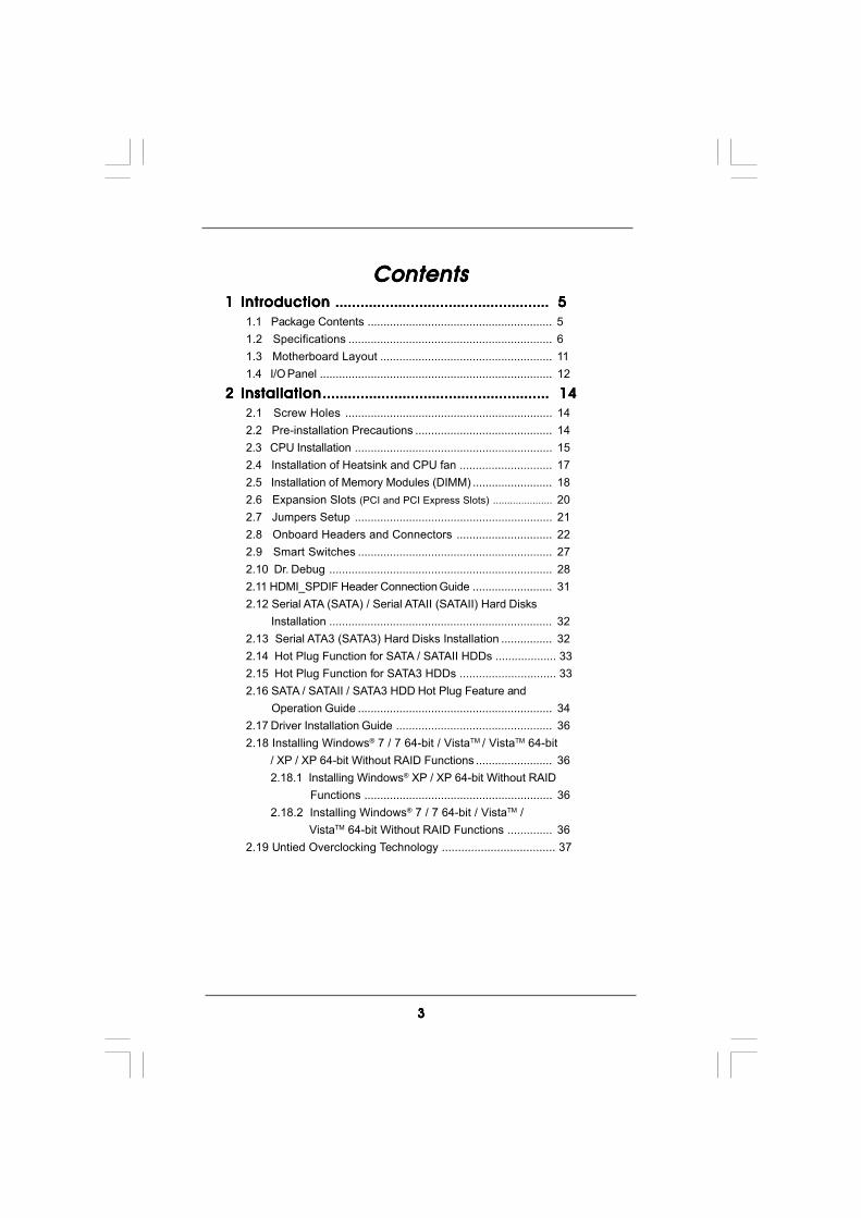
ContentsContentsContentsContentsContents1 Introduction1 Introduction1 Introduction1 Introduction1 Introduction ............................................................................................................................................................................................................................................................... 5 5 5 5 5
1.1 Package Contents .......................................................... 51.2 Specifications ................................................................ 61.3 Motherboard Layout ...................................................... 111.4 I/O Panel ......................................................................... 12
2 Installation2 Installation2 Installation2 Installation2 Installation .............................................................................................................................................................................................................................................................................. 14 14 14 14 142.1 Screw Holes ................................................................. 142.2 Pre-installation Precautions ........................................... 142.3 CPU Installation .............................................................. 152.4 Installation of Heatsink and CPU fan ............................. 172.5 Installation of Memory Modules (DIMM) ......................... 182.6 Expansion Slots (PCI and PCI Express Slots) ..................... 202.7 Jumpers Setup .............................................................. 212.8 Onboard Headers and Connectors .............................. 222.9 Smart Switches ............................................................. 272.10 Dr. Debug ...................................................................... 282.11 HDMI_SPDIF Header Connection Guide ......................... 312.12 Serial ATA (SATA) / Serial ATAII (SATAII) Hard Disks Installation ...................................................................... 322.13 Serial ATA3 (SATA3) Hard Disks Installation ................ 322.14 Hot Plug Function for SATA / SATAII HDDs ................... 332.15 Hot Plug Function for SATA3 HDDs .............................. 332.16 SATA / SATAII / SATA3 HDD Hot Plug Feature and Operation Guide ............................................................. 342.17 Driver Installation Guide ................................................. 362.18 Installing Windows® 7 / 7 64-bit / VistaTM / VistaTM 64-bit / XP / XP 64-bit Without RAID Functions ........................ 36
2.18.1 Installing Windows® XP / XP 64-bit Without RAID Functions ........................................................... 362.18.2 Installing Windows® 7 / 7 64-bit / VistaTM / VistaTM 64-bit Without RAID Functions .............. 36
2.19 Untied Overclocking Technology ................................... 37
44444
3 BIOS S3 BIOS S3 BIOS S3 BIOS S3 BIOS SETUP UTILITYETUP UTILITYETUP UTILITYETUP UTILITYETUP UTILITY ....................................................................................................................................................................................................................... 38 38 38 38 38
3.1 Introduction3.1 Introduction3.1 Introduction3.1 Introduction3.1 Introduction ................................................................................................................................................................................................................................. 38 38 38 38 383.1.1 BIOS Menu Bar .................................................... 383.1.2 Navigation Keys ................................................... 39
3.2 Main Screen................................................................... 393.3 OC Tweaker Screen ...................................................... 403.4 Advanced Screen ......................................................... 44
3.4.1 CPU Configuration ................................................ 453.4.2 Chipset Configuration .......................................... 473.4.3 ACPI Configuration ............................................... 493.4.4 Storage Configuration ......................................... 503.4.5 PCIPnP Configuration ........................................... 523.4.6 Super IO Configuration ........................................ 533.4.7 USB Configuration ............................................... 54
3.5 Hardware Health Event Monitoring Screen .................. 553.6 Boot Screen................................................................... 56
3.6.1 Boot Settings Configuration .................................. 563.7 Security Screen ............................................................ 573.8 Exit Screen .................................................................... 58
4 Software Support4 Software Support4 Software Support4 Software Support4 Software Support ....................................................................................................................................................................................................................... 59 59 59 59 594.1 Install Operating System ............................................... 594.2 Support CD Information ................................................. 59
4.2.1 Running Support CD ............................................ 594.2.2 Drivers Menu ........................................................ 594.2.3 Utilities Menu ........................................................ 594.2.4 Contact Information .............................................. 59

55555
Chapter 1: IntroductionChapter 1: IntroductionChapter 1: IntroductionChapter 1: IntroductionChapter 1: IntroductionThank you for purchasing ASRock H55 Extreme3 motherboard, a reliable motherboardproduced under ASRock’s consistently stringent quality control. It delivers excellentperformance with robust design conforming to ASRock’s commitment to quality andendurance.In this manual, chapter 1 and 2 contain introduction of the motherboard and step-by-stepguide to the hardware installation. Chapter 3 and 4 contain the configuration guide toBIOS setup and information of the Support CD.
Because the motherboard specifications and the BIOS software mightbe updated, the content of this manual will be subject to change withoutnotice. In case any modifications of this manual occur, the updatedversion will be available on ASRock website without further notice. Youmay find the latest VGA cards and CPU support lists on ASRock websiteas well. ASRock website http://www.asrock.comIf you require technical support related to this motherboard, please visitour website for specific information about the model you are using.www.asrock.com/support/index.asp
1.1 P1.1 P1.1 P1.1 P1.1 Packackackackackage Contentsage Contentsage Contentsage Contentsage ContentsASRock H55 Extreme3 Motherboard
(ATX Form Factor: 12.0-in x 9.6-in, 30.5 cm x 24.4 cm)ASRock H55 Extreme3 Quick Installation GuideASRock H55 Extreme3 Support CD4 x Serial ATA (SATA) Data Cables (Optional)1 x Serial ATA (SATA) HDD Power Cable (Optional)1 x I/O Panel Shield

66666
1.21.21.21.21.2 SpecificationsSpecificationsSpecificationsSpecificationsSpecifications
Platform - ATX Form Factor: 12.0-in x 9.6-in, 30.5 cm x 24.4 cm- All Solid Capacitor design (100% Japan-made high-quality Conductive Polymer Capacitors)
CPU - Supports Intel® CoreTM i7 / i5 / i3 and Pentium® G6950 Processors in LGA1156 Package- Advanced V8 + 2 Power Phase Design- Supports Intel® Turbo Boost Technology (see CAUTION 1)- Supports Hyper-Threading Technology (see CAUTION 2)- Supports Untied Overclocking Technology (see CAUTION 3)- Supports EM64T CPU
Chipset - Intel® H55 Memory - Dual Channel DDR3 Memory Technology (see CAUTION 4)
- 4 x DDR3 DIMM slots- Supports DDR3 2600+(OC)/2133(OC)/1866(OC)/1600/ 1333/1066 non-ECC, un-buffered memory- Max. capacity of system memory: 16GB (see CAUTION 5)- Supports Intel® Extreme Memory Profile (XMP) (see CAUTION 6)
Expansion Slot - 1 x PCI Express 2.0 x16 slot (blue at x16 mode)- 3 x PCI Express 2.0 x1 slots (2.5GT/s)- 3 x PCI slots
Graphics * * Requires a Processor with Intel® Graphics Technology- Intel® HD Graphics- Pixel Shader 4.0, DirectX 10- Max. shared memory 1759MB (see CAUTION 7)- Three VGA Output options: D-Sub, DVI-D and HDMI (see CAUTION 8)- Supports HDMI 1.3a Technology with max. resolution up to 1920x1200- Supports DVI with max. resolution up to 1920x1200 @ 60Hz- Supports D-Sub with max. resolution up to 2048x1536 @ 75Hz- Supports Auto Lip Sync, Deep Color (12bpc), xvYCC and HBR (High Bit Rate Audio) with HDMI 1.3a (Compliant HDMI monitor is required) (see CAUTION 9)- Supports HDCP function with DVI and HDMI ports- Supports Full HD 1080p Blu-ray (BD) / HD-DVD playback with DVI and HDMI ports

77777
Audio - 7.1 CH HD Audio with Content Protection- DAC with 110dB dynamic range (VIA® VT2020 Audio Codec)- Supports HDMI Audio with Dolby True HD and DTS HD Master Audio (when Intel® CoreTM i5 600 series / i3 500 series / Pentium® G6950 CPU is installed)- Premium Blu-ray audio support
LAN - PCIE x1 Gigabit LAN 10/100/1000 Mb/s- Realtek RTL8111DL- Supports Wake-On-LAN
Rear Panel I/O I/O Panel- 1 x PS/2 Keyboard Port- 1 x VGA/D-Sub Port- 1 x VGA/DVI-D Port- 1 x HDMI Port- 1 x Optical SPDIF Out Port- 5 x Ready-to-Use USB 2.0 Ports- 1 x eSATA3 Connector- 1 x Ready-to-Use USB 3.0 Port- 1 x RJ-45 LAN Port with LED (ACT/LINK LED and SPEED LED)- 1 x IEEE 1394 Port- HD Audio Jack: Rear Speaker/Central/Bass/Line in/Front Speaker/Microphone (see CAUTION 10)
SATA3 - 2 x SATA3 6.0Gb/s connectors by Marvell SE9123/9120, support NCQ, AHCI and “Hot Plug” functions (SATA3_2 connector is shared with eSATA3 port)
USB 3.0 - 1 x USB3.0 port by Fresco FL1000G, supports USB 3.0 up to 5Gb/s
Connector - 6 x SATAII 3.0Gb/s connectors, support NCQ, AHCI and “Hot Plug” functions- 2 x SATA3 6.0Gb/s connectors- 1 x IR header- 1 x COM port header- 1 x HDMI_SPDIF header- 1 x IEEE 1394 header- 1 x Chassis Intrusion header- 1 x Power LED header- CPU/Chassis/Power FAN connector- 24 pin ATX power connector- 8 pin 12V power connector- Front panel audio connector
88888
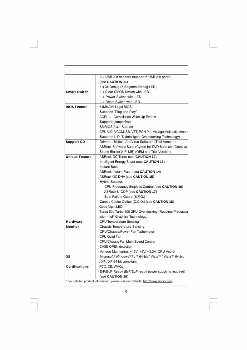
- 3 x USB 2.0 headers (support 6 USB 2.0 ports) (see CAUTION 11)- 1 x Dr. Debug (7-Segment Debug LED)
Smart Switch - 1 x Clear CMOS Switch with LED- 1 x Power Switch with LED- 1 x Reset Switch with LED
BIOS Feature - 64Mb AMI Legal BIOS- Supports “Plug and Play”- ACPI 1.1 Compliance Wake Up Events- Supports jumperfree- SMBIOS 2.3.1 Support- CPU VID, VCCM, SB, VTT, PCH PLL Voltage Multi-adjustment- Supports I. O. T. (Intelligent Overclocking Technology)
Support CD - Drivers, Utilities, AntiVirus Software (Trial Version), ASRock Software Suite (CyberLink DVD Suite and Creative Sound Blaster X-Fi MB) (OEM and Trial Version)
Unique Feature - ASRock OC Tuner (see CAUTION 12)- Intelligent Energy Saver (see CAUTION 13)- Instant Boot- ASRock Instant Flash (see CAUTION 14)- ASRock OC DNA (see CAUTION 15)- Hybrid Booster:
- CPU Frequency Stepless Control (see CAUTION 16)- ASRock U-COP (see CAUTION 17)- Boot Failure Guard (B.F.G.)
- Combo Cooler Option (C.C.O.) (see CAUTION 18)- Good Night LED- Turbo 50 / Turbo 100 GPU Overclocking (Requires Processor with Intel® Graphics Technology)
Hardware - CPU Temperature Sensing Monitor - Chassis Temperature Sensing
- CPU/Chassis/Power Fan Tachometer- CPU Quiet Fan- CPU/Chassis Fan Multi-Speed Control- CASE OPEN detection- Voltage Monitoring: +12V, +5V, +3.3V, CPU Vcore
OS - Microsoft® Windows® 7 / 7 64-bit / VistaTM / VistaTM 64-bit / XP / XP 64-bit compliant
Certifications - FCC, CE, WHQL- ErP/EuP Ready (ErP/EuP ready power supply is required) (see CAUTION 19)
* For detailed product information, please visit our website: http://www.asrock.com
99999
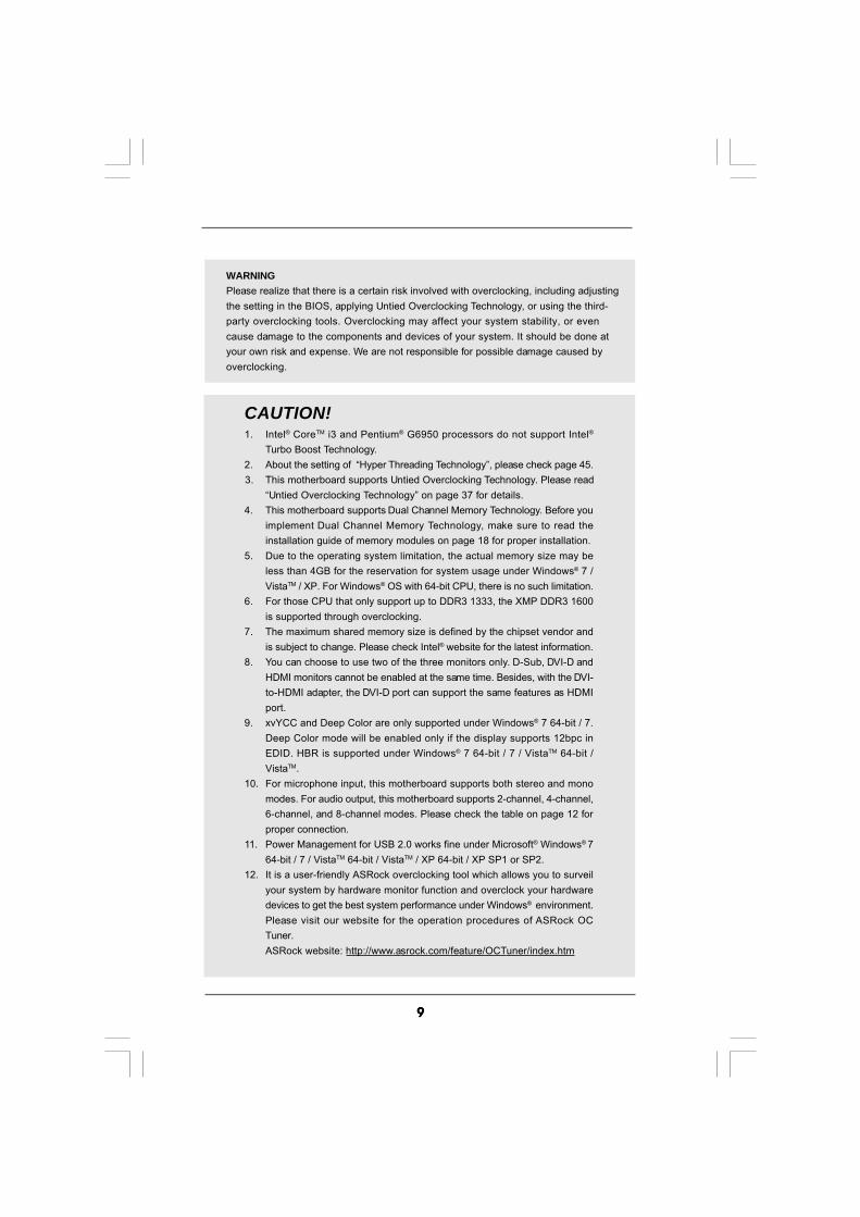
WARNINGPlease realize that there is a certain risk involved with overclocking, including adjustingthe setting in the BIOS, applying Untied Overclocking Technology, or using the third-party overclocking tools. Overclocking may affect your system stability, or evencause damage to the components and devices of your system. It should be done atyour own risk and expense. We are not responsible for possible damage caused byoverclocking.
CAUTION!1. Intel® CoreTM i3 and Pentium® G6950 processors do not support Intel®
Turbo Boost Technology.2. About the setting of “Hyper Threading Technology”, please check page 45.3. This motherboard supports Untied Overclocking Technology. Please read
“Untied Overclocking Technology” on page 37 for details.4. This motherboard supports Dual Channel Memory Technology. Before you
implement Dual Channel Memory Technology, make sure to read theinstallation guide of memory modules on page 18 for proper installation.
5. Due to the operating system limitation, the actual memory size may beless than 4GB for the reservation for system usage under Windows® 7 /VistaTM / XP. For Windows® OS with 64-bit CPU, there is no such limitation.
6. For those CPU that only support up to DDR3 1333, the XMP DDR3 1600is supported through overclocking.
7. The maximum shared memory size is defined by the chipset vendor andis subject to change. Please check Intel® website for the latest information.
8. You can choose to use two of the three monitors only. D-Sub, DVI-D andHDMI monitors cannot be enabled at the same time. Besides, with the DVI-to-HDMI adapter, the DVI-D port can support the same features as HDMIport.
9. xvYCC and Deep Color are only supported under Windows® 7 64-bit / 7.Deep Color mode will be enabled only if the display supports 12bpc inEDID. HBR is supported under Windows® 7 64-bit / 7 / VistaTM 64-bit /VistaTM.
10. For microphone input, this motherboard supports both stereo and monomodes. For audio output, this motherboard supports 2-channel, 4-channel,6-channel, and 8-channel modes. Please check the table on page 12 forproper connection.
11. Power Management for USB 2.0 works fine under Microsoft® Windows® 764-bit / 7 / VistaTM 64-bit / VistaTM / XP 64-bit / XP SP1 or SP2.
12. It is a user-friendly ASRock overclocking tool which allows you to surveilyour system by hardware monitor function and overclock your hardwaredevices to get the best system performance under Windows® environment.Please visit our website for the operation procedures of ASRock OCTuner.ASRock website: http://www.asrock.com/feature/OCTuner/index.htm

1 01 01 01 01 0
13. Featuring an advanced proprietary hardware and software design,Intelligent Energy Saver is a revolutionary technology that deliversunparalleled power savings. In other words, it is able to provide exceptionalpower saving and improve power efficiency without sacrificing computingperformance. Please visit our website for the operation procedures ofIntelligent Energy Saver.ASRock website: http://www.asrock.com/feature/IES/index.html
14. ASRock Instant Flash is a BIOS flash utility embedded in Flash ROM.This convenient BIOS update tool allows you to update system BIOSwithout entering operating systems first like MS-DOS or Windows®. Withthis utility, you can press <F6> key during the POST or press <F2> key toBIOS setup menu to access ASRock Instant Flash. Just launch this tooland save the new BIOS file to your USB flash drive, floppy disk or harddrive, then you can update your BIOS only in a few clicks without prepar-ing an additional floppy diskette or other complicated flash utility. Pleasebe noted that the USB flash drive or hard drive must use FAT32/16/12 filesystem.
15. The software name itself – OC DNA literally tells you what it is capable of.OC DNA, an exclusive utility developed by ASRock, provides a conve-nient way for the user to record the OC settings and share with others. Ithelps you to save your overclocking record under the operating systemand simplifies the complicated recording process of overclocking settings.With OC DNA, you can save your OC settings as a profile and share withyour friends! Your friends then can load the OC profile to their own systemto get the same OC settings as yours! Please be noticed that the OCprofile can only be shared and worked on the same motherboard.
16. Although this motherboard offers stepless control, it is not recommendedto perform over-clocking. Frequencies other than the recommended CPUbus frequencies may cause the instability of the system or damage theCPU.
17. While CPU overheat is detected, the system will automatically shutdown.Before you resume the system, please check if the CPU fan on themotherboard functions properly and unplug the power cord, then plug itback again. To improve heat dissipation, remember to spray thermalgrease between the CPU and the heatsink when you install the PC system.
18. Combo Cooler Option (C.C.O.) provides the flexible option to adopt twodifferent CPU cooler types, Socket LGA 775 and LGA 1156. Please benoticed that not all the 775 CPU Fan can be used.
19. EuP, stands for Energy Using Product, was a provision regulated byEuropean Union to define the power consumption for the completed system.According to EuP, the total AC power of the completed system shall beunder 1.00W in off mode condition. To meet EuP standard, an EuP readymotherboard and an EuP ready power supply are required. According toIntel’s suggestion, the EuP ready power supply must meet the standard of5v standby power efficiency is higher than 50% under 100 mA currentconsumption. For EuP ready power supply selection, we recommend youchecking with the power supply manufacturer for more details.

1 11 11 11 11 1
1.3 Motherboard Layout1.3 Motherboard Layout1.3 Motherboard Layout1.3 Motherboard Layout1.3 Motherboard Layout
1 PS2_USB_PWR1 Jumper 22 System Panel Header (PANEL1, White) 2 Power Fan Connector (PWR_FAN1) 23 Clear CMOS Jumper (CLRCMOS1) 3 CPU Fan Connector (CPU_FAN1) 24 Power LED Header (PLED1) 4 ATX 12V Power Connector (ATX12V1) 25 Dr. Debug 5 1156-Pin CPU Socket 26 USB_PWR3 Jumper 6 2 x 240-pin DDR3 DIMM Slots 27 USB 2.0 Header (USB11_12, Blue)
(Dual Channel: DDR3_A2, DDR3_B2, Blue) 28 USB 2.0 Header (USB9_10, Blue) 7 2 x 240-pin DDR3 DIMM Slots 29 USB 2.0 Header (USB7_8, Blue)
(Dual Channel: DDR3_A1, DDR3_B1, White) 30 Front Panel IEEE 1394 Header 8 ATX Power Connector (ATXPWR1) (FRONT_1394, White) 9 Chassis Fan Connector (CHA_FAN1) 31 Chassis Fan Connector (CHA_FAN3)10 Chassis Fan Connector (CHA_FAN2) 32 Infrared Module Header (IR1)11 Intel H55 Chipset 33 COM Port Header (COM1)12 SATAII Connector (SATAII_0_1, Blue) 34 HDMI_SPDIF Header (HDMI_SPDIF1, White)13 SATAII Connector (SATAII_2_3, Blue) 35 Front Panel Audio Header14 SATAII Connector (SATAII_4_5, Blue) (HD_AUDIO1, White)15 SATA3 Connector (SATA3_1_2, White) 36 PCI Slots (PCI1-3)16 Clear CMOS Switch (CLRCBTN) 37 PCI Express 2.0 x1 Slot (PCIE4, White)17 Reset Switch (RSTBTN) 38 PCI Express 2.0 x1 Slot (PCIE3, White)18 64Mb SPI Flash 39 PCI Express 2.0 x16 Slot (PCIE2, Blue)19 Power Switch (PWRBTN) 40 PCI Express 2.0 x1 Slot (PCIE1, White)20 Chassis Intrusion Header (CI1) 41 USB_PWR2 Jumper21 Chassis Speaker Header (SPEAKER 1, White)
24.4cm (9.6 in)
30
.5c
m(1
2.0
in)
DD
R3
_A
2(6
4b
it,
24
0-p
inm
od
ule
)
DD
R3
_A
1(6
4b
it,
24
0-p
inm
od
ule
)
DD
R3
_B
2(6
4b
it,
24
0-p
inm
od
ule
)
DD
R3
_B
1(6
4b
it,
24
0-p
inm
od
ule
)
AT
XP
WR
1C
HA
_F
AN
1C
HA
_F
AN
2
SA
TA
II_
2_
3S
AT
AII
_0
_1
SA
TA
3_
1_
2S
AT
AII
_4
_5
IntelH55
VIAVT6308S
SPEAKER1
1
Dr.Debug
64MbBIOS
CI1
1
CMOSBattery
CLRCMOS1
1
PWRBTN
RSTBTN
IR1
HDLED RESET
PLED PWRBTN
PANEL111
PLED1
1
clrCMOS
USB11_12USB9_10
11
FRONT_1394
11 11
USB7_8
11
SuperI/O
AUDIOCODEC
LANPHY
1
HD_AUDIO1COM1
11
HDMI_SPDIF1
CHA_FAN3
PCIE1
PCIE2
PCIE3
PCIE4
PCI1
PCI2
PCI3
RoHS
H55 Extreme3
1394a
PCI Express 2.0D
DR
32
60
0+
Du
alC
ha
nn
el
ErP/EuP Ready Design in Taipei
USB 3.0 SATA3 6Gb/s
DX10
ATX12V1
PS2_USB_PWR11
USB_PWR21
USB_PWR3
1
PWR_FAN1 CPU_FAN1
FRESCOFL1000G
To
p:
CT
RB
AS
S
Ce
nte
r:R
EA
RS
PK
Bo
ttom
:O
ptic
al
SP
DIF
To
p:
LIN
EIN
Ce
nte
r:F
RO
NT
Bo
ttom
:M
ICIN
RJ-45
LA
N
US
B3.0
(US
B5)
US
B2.0
(US
B4)
eSA
TA3_1
IEE
E1394
USB 2.0T: USB0B: USB1
PS
2K
ey
bo
ard
VGA
1
DV
I_C
ON
1
HD
MI1
1 2 3 4 5 6 7
8
9
10
11
12
13
14
15
16
17
23
18
19
20
21
22242526272829303132333435
36
37
38
39
40
41
Marvell9123/9120
USB 2.0T: USB2B: USB3
1 21 21 21 21 2
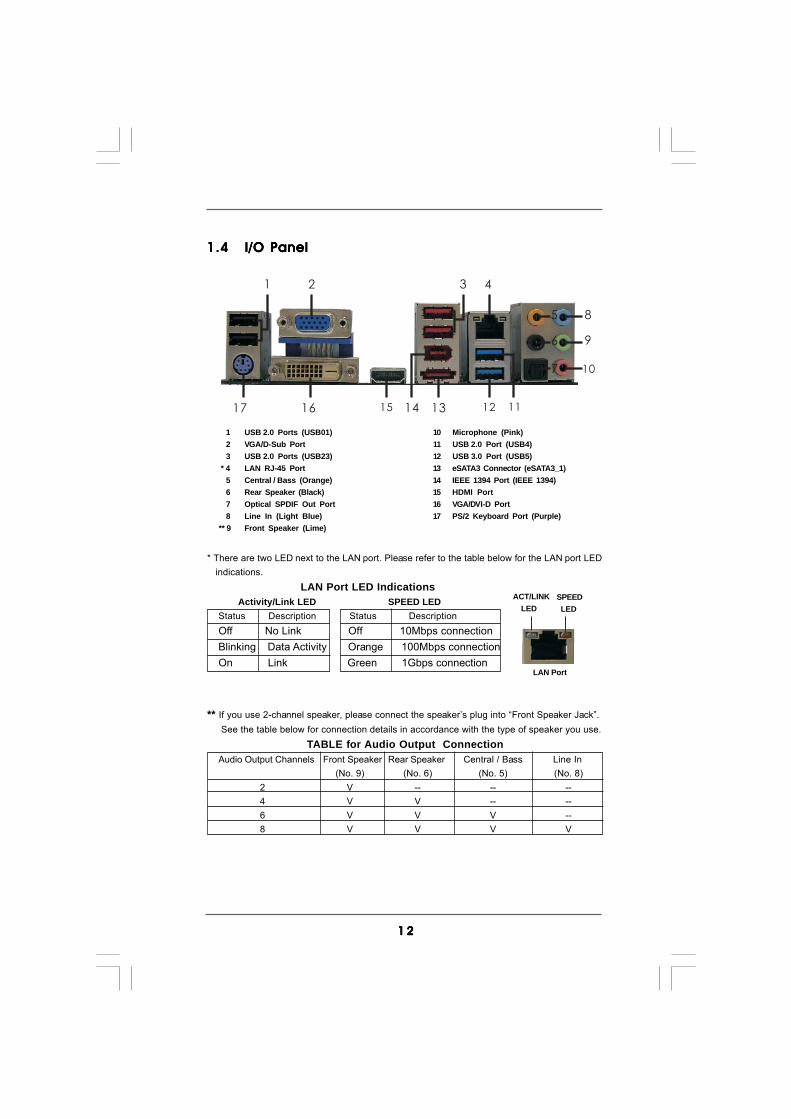
1.41.41.41.41.4 I/O PanelI/O PanelI/O PanelI/O PanelI/O Panel
** If you use 2-channel speaker, please connect the speaker’s plug into “Front Speaker Jack”. See the table below for connection details in accordance with the type of speaker you use.
TABLE for Audio Output ConnectionAudio Output Channels Front Speaker Rear Speaker Central / Bass Line In
(No. 9) (No. 6) (No. 5) (No. 8)2 V -- -- --4 V V -- --6 V V V --8 V V V V
LAN Port
ACT/LINK LED
SPEED LED
* There are two LED next to the LAN port. Please refer to the table below for the LAN port LED indications.
LAN Port LED Indications Activity/Link LED SPEED LEDStatus Description Status DescriptionOff No Link Off 10Mbps connectionBlinking Data Activity Orange 100Mbps connectionOn Link Green 1Gbps connection
1 2 43
5
6
7
8
9
10
111314 121617 15
1 USB 2.0 Ports (USB01) 10 Microphone (Pink)2 VGA/D-Sub Port 11 USB 2.0 Port (USB4)3 USB 2.0 Ports (USB23) 12 USB 3.0 Port (USB5)
* 4 LAN RJ-45 Port 13 eSATA3 Connector (eSATA3_1)5 Central / Bass (Orange) 14 IEEE 1394 Port (IEEE 1394)6 Rear Speaker (Black) 15 HDMI Port7 Optical SPDIF Out Port 16 VGA/DVI-D Port8 Line In (Light Blue) 17 PS/2 Keyboard Port (Purple)
** 9 Front Speaker (Lime)

1 31 31 31 31 3
To enable Multi-Streaming function, you need to connect a front panel audio cable to the front panel audio header. After restarting your computer, you will find “VIA HD Audio Deck” tool on your system. Please follow below instructions according to the OS you install.
For Windows® XP / XP 64-bit OS: Please click “VIA HD Audio Deck” icon. Click “Jack” and then click “Configuration”. In “Configuration” screen, please check the item “Independent Headphone”.
For Windows® 7 / 7 64-bit / VistaTM / VistaTM 64-bit OS: Please click “VIA HD Audio Deck” icon. Click “Advanced Options” on the right side on the bottom. In “Advanced Options” screen, please check the item “Independent Headphone”.

1 41 41 41 41 4
Chapter 2: InstallationChapter 2: InstallationChapter 2: InstallationChapter 2: InstallationChapter 2: InstallationThis is an ATX form factor (12.0" x 9.6", 30.5 x 24.4 cm) motherboard. Before youinstall the motherboard, study the configuration of your chassis to ensure that themotherboard fits into it.
Make sure to unplug the power cord before installing or removing themotherboard. Failure to do so may cause physical injuries to you anddamages to motherboard components.
2.1 Screw Holes2.1 Screw Holes2.1 Screw Holes2.1 Screw Holes2.1 Screw HolesPlace screws into the holes indicated by circles to secure the motherboard to thechassis.
Do not over-tighten the screws! Doing so may damage the motherboard.
2.2 Pre-installation Precautions2.2 Pre-installation Precautions2.2 Pre-installation Precautions2.2 Pre-installation Precautions2.2 Pre-installation PrecautionsTake note of the following precautions before you install motherboard componentsor change any motherboard settings.
1. Unplug the power cord from the wall socket before touching any component.2. To avoid damaging the motherboard components due to static electricity, NEVER
place your motherboard directly on the carpet or the like. Also remember to usea grounded wrist strap or touch a safety grounded object before you handlecomponents.
3. Hold components by the edges and do not touch the ICs.4. Whenever you uninstall any component, place it on a grounded antistatic pad or
in the bag that comes with the component.
Before you install or remove any component, ensure that the power is switched off or the power cord is detached from the power supply. Failure to do so may cause severe damage to the motherboard, peripherals, and/or components.

1 51 51 51 51 5
2.3 CPU Installation2.3 CPU Installation2.3 CPU Installation2.3 CPU Installation2.3 CPU InstallationFor the installation of Intel 1156-Pin CPU,please follow the steps below.
Before you insert the 1156-Pin CPU into the socket, please check ifthe CPU surface is unclean or if there is any bent pin on the socket.Do not force to insert the CPU into the socket if above situation isfound. Otherwise, the CPU will be seriously damaged.
Step 1. Open the socket:Step 1-1. Disengaging the lever by depressing
down and out on the hook to clearretention tab.
Step 1-2. Rotate the load lever to fully open po-sition at approximately 135 degrees.
Step 1-3. Rotate the load plate to fully open po-sition at approximately 100 degrees.
Step 2. Remove PnP Cap (Pick and Place Cap).
1. It is recommended to use the cap tab to handle and avoid kicking off the PnP cap.2. This cap must be placed if returning the motherboard for after service.
1156-Pin Socket Overview
Contact ArraySocket Body
Load Lever
Load Plate

1 61 61 61 61 6
black line
Pin1
alignment key
alignment key
Pin1
1156-Pin CPU
1156-Pin Socket
Step 3. Insert the 1156-Pin CPU:Step 3-1. Hold the CPU by the edge where is
marked with black line.
Step 3-2. Orient the CPU with IHS (Integrated HeatSink) up. Locate Pin1 and the two ori-entation key notches.
For proper inserting, please ensure to match the two orientation keynotches of the CPU with the two alignment keys of the socket.
Step 3-3. Carefully place the CPU into the socketby using a purely vertical motion.
Step 3-4. Verify that the CPU is within the socketand properly mated to the orient keys.
Step 4. Close the socket:Step 4-1. Rotate the load plate onto the IHS.Step 4-2. While pressing down lightly on load
plate, engage the load lever.Step 4-3. Secure load lever with load plate tab
under retention tab of load lever.
orientation key notch
orientation key notch

1 71 71 71 71 7
2.42.42.42.42.4 Installation of CPU Fan and HeatsinkInstallation of CPU Fan and HeatsinkInstallation of CPU Fan and HeatsinkInstallation of CPU Fan and HeatsinkInstallation of CPU Fan and HeatsinkThis motherboard is equipped with 1156-Pin socket that supports Intel 1156-Pin CPU.Please adopt the type of heatsink and cooling fan compliant with Intel 1156-Pin CPUto dissipate heat. Before you installed the heatsink, you need to spray thermalinterface material between the CPU and the heatsink to improve heat dissipation.Ensure that the CPU and the heatsink are securely fastened and in good contact witheach other. Then connect the CPU fan to the CPU_FAN connector (CPU_FAN1, seepage 11, No. 3).For proper installation, please kindly refer to the instruction manuals of yourCPU fan and heatsink.
Below is an example to illustrate the installation of the heatsink for 1156-Pin CPU.Step 1. Apply thermal interface material onto center of
IHS on the socket surface.
Step 2. Place the heatsink onto the socket. Ensurefan cables are oriented on side closest to theCPU fan connector on the motherboard(CPU_FAN1, see page 11, No. 3).
Step 3. Align fasteners with the motherboardthroughholes.
Step 4. Rotate the fastener clockwise, then pressdown on fastener caps with thumb to installand lock. Repeat with remaining fasteners.
If you press down the fasteners without rotating them clockwise,the heatsink cannot be secured on the motherboard.
Step 5. Connect fan header with the CPU fan connector on the motherboard.Step 6. Secure excess cable with tie-wrap to ensure cable does not interfere with
fan operation or contact other components.
Apply ThermalInterface Material
Fan cables on sideclosest to MB header
Fastener slotspointing straight out
Press Down(4 Places)
Please be noticed that this motherboard supports Combo CoolerOption (C.C.O.), which provides the flexible option to adopt twodifferent CPU cooler types, Socket LGA 775 and LGA 1156. Thewhite throughholes are for Socket LGA 1156 CPU fan.

1 81 81 81 81 8
2.5 Installation of Memory Modules (DIMM)2.5 Installation of Memory Modules (DIMM)2.5 Installation of Memory Modules (DIMM)2.5 Installation of Memory Modules (DIMM)2.5 Installation of Memory Modules (DIMM)This motherboard provides four 240-pin DDR3 (Double Data Rate 3) DIMM slots,and supports Dual Channel Memory Technology. For dual channel configuration,you always need to install identical (the same brand, speed, size and chip-type) DDR3 DIMM pair in the slots of the same color. In other words, you have toinstall identical DDR3 DIMM pair in Dual Channel (DDR3_A1 and DDR3_B1;white slots; see p.11 No.7), so that Dual Channel Memory Technology can beactivated. This motherboard also allows you to install four DDR3 DIMMs for dualchannel configuration, and please install identical DDR3 DIMMs in all four slots.You may refer to the Dual Channel Memory Configuration Table below.
Dual Channel Memory Configurations
DDR3_A2 DDR3_A1 DDR3_B2 DDR3_B1(Blue Slot) (White Slot) (Blue Slot) (White Slot)
(1) - Populated - Populated(2)* Populated Populated Populated Populated
* For the configuration (2), please install identical DDR3 DIMMs in all four
slots.
1. If you want to install two memory modules, for optimal compatibilityand reliability, it is recommended to install them in the slots of thesame color. In other words, install them either in the set of white slots(DDR3_A1 and DDR3_B1).
2. If only one memory module or three memory modules are installedin the DDR3 DIMM slots on this motherboard, it is unable to activatethe Dual Channel Memory Technology.
3. It is not allowed to install a DDR or DDR2 memory module intoDDR3 slot;otherwise, this motherboard and DIMM may be damaged.
4. Please install the memory module into the white slot (DDR3_B1) forthe first priority.

1 91 91 91 91 9
notch
break
notchbreak
Installing a DIMMInstalling a DIMMInstalling a DIMMInstalling a DIMMInstalling a DIMM
Please make sure to disconnect power supply before adding orremoving DIMMs or the system components.
Step 1. Unlock a DIMM slot by pressing the retaining clips outward.Step 2. Align a DIMM on the slot such that the notch on the DIMM matches the break
on the slot.
The DIMM only fits in one correct orientation. It will cause permanentdamage to the motherboard and the DIMM if you force the DIMM into the slotat incorrect orientation.
Step 3. Firmly insert the DIMM into the slot until the retaining clips at both ends fullysnap back in place and the DIMM is properly seated.

2 02 02 02 02 0
2.6 Expansion Slots (PCI and PCI Express Slots)2.6 Expansion Slots (PCI and PCI Express Slots)2.6 Expansion Slots (PCI and PCI Express Slots)2.6 Expansion Slots (PCI and PCI Express Slots)2.6 Expansion Slots (PCI and PCI Express Slots)There are 3 PCI slots and 4 PCI Express slots on this motherboard.PCI slot: PCI slot is used to install expansion cards that have the 32-bit PCI
interface.PCIE slots:
PCIE1 / PCIE3 / PCIE4 (PCIE x1 slot; White) is used for PCI Expresscards with x1 lane width cards, such as Gigabit LAN card, SATA2card, etc.PCIE2 (PCIE x16 slot; Blue) is used for PCI Express x16 lane widthgraphics cards.
Installing an expansion cardInstalling an expansion cardInstalling an expansion cardInstalling an expansion cardInstalling an expansion cardStep 1. Before installing the expansion card, please make sure that the power
supply is switched off or the power cord is unplugged. Please read thedocumentation of the expansion card and make necessary hardwaresettings for the card before you start the installation.
Step 2. Remove the system unit cover (if your motherboard is already installed ina chassis).
Step 3. Remove the bracket facing the slot that you intend to use. Keep thescrews for later use.
Step 4. Align the card connector with the slot and press firmly until the card iscompletely seated on the slot.
Step 5. Fasten the card to the chassis with screws.Step 6. Replace the system cover.
2 12 12 12 12 1
+5V
1_2
+5VSB
2_3
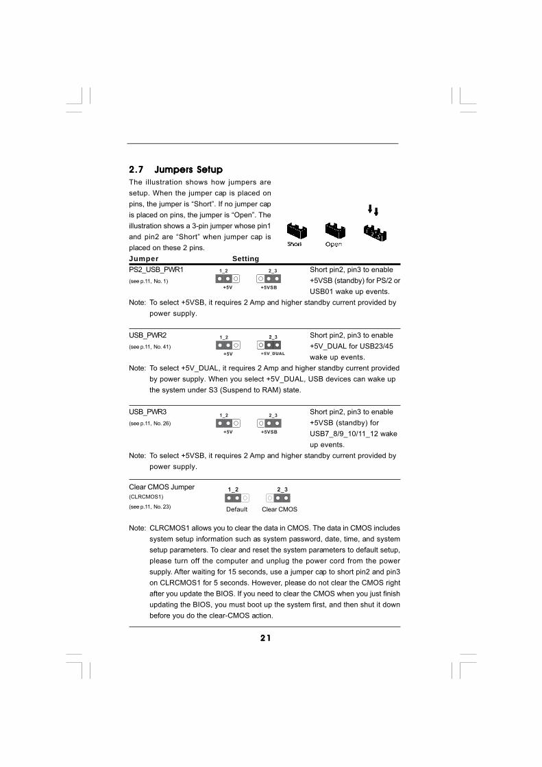
2.72.72.72.72.7 Jumpers SetupJumpers SetupJumpers SetupJumpers SetupJumpers SetupThe illustration shows how jumpers aresetup. When the jumper cap is placed onpins, the jumper is “Short”. If no jumper capis placed on pins, the jumper is “Open”. Theillustration shows a 3-pin jumper whose pin1and pin2 are “Short” when jumper cap isplaced on these 2 pins.Jumper SettingPS2_USB_PWR1 Short pin2, pin3 to enable(see p.11, No. 1) +5VSB (standby) for PS/2 or
USB01 wake up events.Note: To select +5VSB, it requires 2 Amp and higher standby current provided by
power supply.
USB_PWR2 Short pin2, pin3 to enable(see p.11, No. 41) +5V_DUAL for USB23/45
wake up events.Note: To select +5V_DUAL, it requires 2 Amp and higher standby current provided
by power supply. When you select +5V_DUAL, USB devices can wake upthe system under S3 (Suspend to RAM) state.
USB_PWR3 Short pin2, pin3 to enable(see p.11, No. 26) +5VSB (standby) for
USB7_8/9_10/11_12 wakeup events.
Note: To select +5VSB, it requires 2 Amp and higher standby current provided bypower supply.
Clear CMOS Jumper(CLRCMOS1)
(see p.11, No. 23)
Note: CLRCMOS1 allows you to clear the data in CMOS. The data in CMOS includessystem setup information such as system password, date, time, and systemsetup parameters. To clear and reset the system parameters to default setup,please turn off the computer and unplug the power cord from the powersupply. After waiting for 15 seconds, use a jumper cap to short pin2 and pin3on CLRCMOS1 for 5 seconds. However, please do not clear the CMOS rightafter you update the BIOS. If you need to clear the CMOS when you just finishupdating the BIOS, you must boot up the system first, and then shut it downbefore you do the clear-CMOS action.
Clear CMOS
2_31_2
Default
+5V
1_2
+5VSB
2_3
+5V
1_2
+5V_DUAL

2 22 22 22 22 2
If you clear the CMOS, the case open may be detected. Please adjustthe BIOS option “Clear Status” to clear the record of previous chassisintrusion status.
SATA
II_4_
5
SA
TAII_
2_3
SATA
II_0_
1
Serial ATA3 Connectors These two Serial ATA3(SATA3_1_2: see p.11, No. 15) (SATA3) connectors support
SATA data cables for internalstorage devices. The currentSATA3 interface allows up to6.0 Gb/s data transfer rate.
SATA
3_1_
2
2.8 Onboard Headers and Connectors2.8 Onboard Headers and Connectors2.8 Onboard Headers and Connectors2.8 Onboard Headers and Connectors2.8 Onboard Headers and Connectors
Onboard headers and connectors are NOT jumpers. Do NOT placejumper caps over these headers and connectors. Placing jumper capsover the headers and connectors will cause permanent damage of themotherboard!
Serial ATAII Connectors These six Serial ATAII (SATAII)(SATAII_0_1: connectors support SATA datasee p.11, No. 12) cables for internal storage(SATAII_2_3: devices. The current SATAIIsee p.11, No. 13) interface allows up to 3.0 Gb/s(SATAII_4_5: data transfer rate.see p.11, No. 14)
connect to the SATA HDDpower connector
connect to thepower supply
Serial ATA (SATA) Please connect the black end ofPower Cable SATA power cable to the power(Optional) connector on each drive. Then
connect the white end of SATApower cable to the powerconnector of the power supply.
Serial ATA (SATA) Either end of the SATA data cableData Cable can be connected to the SATA /(Optional) SATAII / SATA3 hard disk or the
SATAII / SATA3 connector on thismotherboard.

2 32 32 32 32 3
USB 2.0 Headers Besides five default USB 2.0(9-pin USB7_8) ports on the I/O panel, there are(see p.11 No. 29) three USB 2.0 headers on this
motherboard. Each USB 2.0header can support two USB2.0 ports.
(9-pin USB9_10)(see p.11 No. 28)
(9-pin USB11_12)(see p.11 No. 27)
1
DUMMYGND
P+8P-8
USB_PWR
USB_PWR
GNDP+7
P-7
1
DUMMYGND
P+10P-10
USB_PWR
USB_PWR
GNDP+9
P-9
1
DUMMYGND
P+12P-12
USB_PWR
USB_PWR
GNDP+11
P-11
Infrared Module Header This header supports an optional(5-pin IR1) wireless transmitting and(see p.11 No. 32) receiving infrared module.1
IRTX
+5VSB
DUMMY
IRRXGND
J_SENSE
OUT2_L
1
MIC_RETPRESENCE#
GND
OUT2_RMIC2_R
MIC2_L
OUT_RET
Front Panel Audio Header This is an interface for front(9-pin HD_AUDIO1) panel audio cable that allows(see p.11 No. 35) convenient connection and
control of audio devices.
Chassis Intrusion Header This motherboard supports(2-pin CI1) CASE OPEN detection feature(see p.11 No. 20) that detects if the chassis cover
has been removed. This featurerequires a chassis with chassisintrusion detection design.
1
Signal
GND
1. High Definition Audio supports Jack Sensing, but the panel wire on the chassis must support HDA to function correctly. Please follow the
instruction in our manual and chassis manual to install your system.2. If you use AC’97 audio panel, please install it to the front panel audio header as below: A. Connect Mic_IN (MIC) to MIC2_L. B. Connect Audio_R (RIN) to OUT2_R and Audio_L (LIN) to OUT2_L.
C. Connect Ground (GND) to Ground (GND). D. MIC_RET and OUT_RET are for HD audio panel only. You don’t need to connect them for AC’97 audio panel.

2 42 42 42 42 4
CPU Fan Connector Please connect a CPU fan cable(4-pin CPU_FAN1) to this connector and match(see p.11 No. 3) the black wire to the ground pin.
GND
PWRBTN#PLED-
PLED+
DUMMYRESET#
GND
HDLED+HDLED-
1
System Panel Header This header accommodates(9-pin PANEL1) several system front panel(see p.11 No. 22) functions.
Chassis Speaker Header Please connect the chassis(4-pin SPEAKER 1) speaker to this header.(see p.11 No. 21)
+5V
DUMMYDUMMY
SPEAKER
1
GND+12V
PWR_FAN_SPEED
GND
+12VCHA_FAN_SPEED
E. Enter BIOS Setup Utility. Enter Advanced Settings, and then select Chipset Configuration. Set the Front Panel Control option from [Auto] to [Enabled].
Power LED Header Please connect the chassis(3-pin PLED1) power LED to this header to(see p.11 No. 24) indicate system power status.
The LED is on when the systemis operating. The LED keepsblinking in S1 state. The LED isoff in S3/S4 state or S5 state(power off).
1
PLED+PLED+
PLED-
Chassis and Power Fan Connectors Please connect the fan cables(4-pin CHA_FAN1) to the fan connectors and(see p.11 No. 9) match the black wire to the
ground pin.
(3-pin CHA_FAN2)(see p.11 No. 10)
(3-pin CHA_FAN3)(see p.11 No. 31)
(3-pin PWR_FAN1)(see p.11 No. 2)
FAN_SPEED_CONTROL
GND
+12V
CHA_FAN_SPEED
GND+12V
CHA_FAN_SPEED
GND+12V
CPU_FAN_SPEEDFAN_SPEED_CONTROL
4 3 2 1
2 52 52 52 52 5
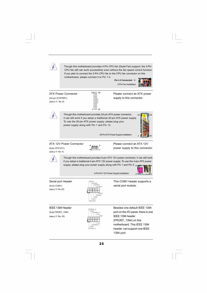
20-Pin ATX Power Supply Installation
Though this motherboard provides 24-pin ATX power connector,it can still work if you adopt a traditional 20-pin ATX power supply.To use the 20-pin ATX power supply, please plug yourpower supply along with Pin 1 and Pin 13.
12
1
24
13
Though this motherboard provides 4-Pin CPU fan (Quiet Fan) support, the 3-Pin CPU fan still can work successfully even without the fan speed control function. If you plan to connect the 3-Pin CPU fan to the CPU fan connector on this motherboard, please connect it to Pin 1-3.
3-Pin Fan Installation
Pin 1-3 Connected
ATX Power Connector Please connect an ATX power(24-pin ATXPWR1) supply to this connector.(see p.11, No. 8)
12
1
24
13
ATX 12V Power Connector Please connect an ATX 12V(8-pin ATX12V1) power supply to this connector.(see p.11 No. 4)
Serial port Header This COM1 header supports a(9-pin COM1) serial port module.(see p.11 No.33)
CCTS#1DDSR#1
DDTR#1RRXD1
DDCD#1TTXD1
GNDRRTS#1
RRI#1
1
4-Pin ATX 12V Power Supply Installation
Though this motherboard provides 8-pin ATX 12V power connector, it can still workif you adopt a traditional 4-pin ATX 12V power supply. To use the 4-pin ATX powersupply, please plug your power supply along with Pin 1 and Pin 5.
8 5
4 1
8 5
4 1
IEEE 1394 Header Besides one default IEEE 1394(9-pin FRONT_1394) port on the I/O panel, there is one(see p.11 No. 30) IEEE 1394 header
(FRONT_1394) on thismotherboard. This IEEE 1394header can support one IEEE1394 port.
+12V
GND+12V
1
RXTPBM_0GND
RXTPAM_0
RXTPBP_0GND
RXTPAP_0
2 62 62 62 62 6
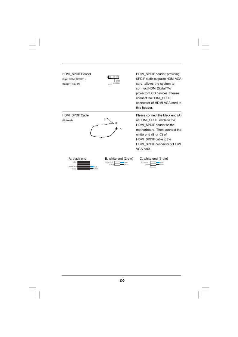
HDMI_SPDIF Cable Please connect the black end (A)(Optional) of HDMI_SPDIF cable to the
HDMI_SPDIF header on themotherboard. Then connect thewhite end (B or C) ofHDMI_SPDIF cable to theHDMI_SPDIF connector of HDMIVGA card.
A. black end B. white end (2-pin) C. white end (3-pin)
CB
GND
+5V
SPDIFOUT blue
black
blue
blackGND
SPDIFOUT blue
blackGND
SPDIFOUT
A
1
GND
+5VSPDIFOUT
HDMI_SPDIF Header HDMI_SPDIF header, providing(3-pin HDMI_SPDIF1) SPDIF audio output to HDMI VGA(see p.11 No. 34) card, allows the system to
connect HDMI Digital TV/projector/LCD devices. Pleaseconnect the HDMI_SPDIFconnector of HDMI VGA card tothis header.

2 72 72 72 72 7
2.9 Smart Switches2.9 Smart Switches2.9 Smart Switches2.9 Smart Switches2.9 Smart SwitchesThis motherboard has three smart switches: power switch, reset switch andclear CMOS switch, allowing users to quickly turn on/off or reset the system orclear the CMOS values.
Power Switch Power Switch is a smart switch,(PWRBTN) allowing users to quickly turn(see p.11 No. 19) on/off the system.
Reset Switch Reset Switch is a smart switch,(RSTBTN) allowing users to quickly reset(see p.11 No. 17) the system.
RESET
Clear CMOS Switch Clear CMOS Switch is a smart(CLRCBTN) switch, allowing users to quickly(see p.11 No. 16) clear the CMOS values
clr
CMOS
You are not allowed to use Clear CMOS switch function if you set up the systempassword. If you want to clear the CMOS values, please clean your systempassword in advance or refer to page 21 “Clear CMOS jumper” descriptioninstead.

2 82 82 82 82 8
2.10 Dr. Debug2.10 Dr. Debug2.10 Dr. Debug2.10 Dr. Debug2.10 Dr. DebugDr. Debug is used to provide code information, which makes troubleshooting eveneasier. Please see the diagrams below for reading the Dr. Debug codes.
The Bootblock initialization code sets up the chipset, memory and othercomponents before system memory is available. The following table describes thetype of checkpoints that may occur during the bootblock initialization portion of theBIOS:
Checkpoint Description Before D1 Early chipset initialization is done. Early super I/O initialization is done
including RTC and keyboard controller. NMI is disabled. D1 Perform keyboard controller BAT test. Check if waking up from power
management suspend state. Save power-on CPUID value in scratchCMOS.
D0 Go to flat mode with 4GB limit and GA20 enabled. Verify the bootblockchecksum.
D2 Disable CACHE before memory detection. Execute full memory sizingmodule. Verify that flat mode is enabled.
D3 If memory sizing module not executed, start memory refresh and domemory sizing in Bootblock code. Do additional chipset initialization.Re-enable CACHE. Verify that flat mode is enabled.
D4 Test base 512KB memory. Adjust policies and cache first 8MB. Set stack. D5 Bootblock code is copied from ROM to lower system memory and control
is given to it. BIOS now executes out of RAM. D6 Both key sequence and OEM specific method is checked to determine if
BIOS recovery is forced. Main BIOS checksum is tested. If BIOS recoveryis necessary, control flows to checkpoint E0.
D7 Restore CPUID value back into register. The Bootblock-Runtime interfacemodule is moved to system memory and control is given to it. Determinewhether to execute serial flash.
D8 The Runtime module is uncompressed into memory. CPUID information isstored in memory.
D9 Store the Uncompressed pointer for future use in PMM. Copying Main BIOSinto memory. Leaves all RAM below 1MB Read-Write including E000 andF000 shadow areas but closing SMRAM.
DA Restore CPUID value back into register. Give control to BIOS POST(ExecutePOSTKernel).

2 92 92 92 92 9
The POST code checkpoints are the largest set of checkpoints during the BIOSpre-boot process. The following table describes the type of checkpoints that mayoccur during the POST portion of the BIOS:
Checkpoint Description 03 Disable NMI, Parity, video for EGA, and DMA controllers. Initialize BIOS,
POST, Runtime data area. Also initialize BIOS modules on POST entry andGPNV area. Initialized CMOS as mentioned in the Kernel Variable“wCMOSFlags.”
04 Check CMOS diagnostic byte to determine if battery power is OK andCMOS checksum is OK. Verify CMOS checksum manually by readingstorage area. If the CMOS checksum is bad, update CMOS with power-ondefault values and clear passwords. Initialize status register A.Initializes data variables that are based on CMOS setup questions.Initializes both the 8259 compatible PICs in the system
05 Initializes the interrupt controlling hardware (generally PIC) and interruptvector table.
06 Do R/W test to CH-2 count reg. Initialize CH-0 as system timer. Install thePOSTINT1Ch handler. Enable IRQ-0 in PIC for system timer interrupt.Traps INT1Ch vector to “POSTINT1ChHandlerBlock.”
08 Initializes the CPU. The BAT test is being done on KBC. Program thekeyboard controller command byte is being done after Auto detection ofKB/MS using AMI KB-5.
C0 Early CPU Init Start — Disable Cache - Init Local APIC C1 Set up boot strap proccessor Information C2 Set up boot strap proccessor for POST C5 Enumerate and set up application proccessors C6 Re-enable cache for boot strap proccessor C7 Early CPU Init Exit 0A Initializes the 8042 compatible Key Board Controller. 0B Detects the presence of PS/2 mouse. 0C Detects the presence of Keyboard in KBC port. 0E Testing and initialization of different Input Devices. Also, update the Kernel
Variables. Traps the INT09h vector, so that the POST INT09h handler getscontrol for IRQ1. Uncompress all available language, BIOS logo, and Silentlogo modules.
13 Early POST initialization of chipset registers. 24 Uncompress and initialize any platform specific BIOS modules. 30 Initialize System Management Interrupt. 2A Initializes different devices through DIM.
See DIM Code Checkpoints section of document for more information. 2C Initializes different devices. Detects and initializes the video adapter
installed in the system that have optional ROMs. 2E Initializes all the output devices. 31 Allocate memory for ADM module and uncompress it. Give control to ADM
module for initialization. Initialize language and font modules for ADM.Activate ADM module.

3 03 03 03 03 0
33 Initializes the silent boot module. Set the window for displaying textinformation.
37 Displaying sign-on message, CPU information, setup key message, andany OEM specific information.
38 Initializes different devices through DIM. 39 Initializes DMAC-1 & DMAC-2. 3A Initialize RTC date/time. 3B Test for total memory installed in the system. Also, Check for DEL or ESC
keys to limit memory test. Display total memory in the system. 3C Mid POST initialization of chipset registers. 40 Detect different devices (Parallel ports, serial ports, and coprocessor in
CPU, etc.) successfully installed in the system and update the BDA,EBDA, etc.
50 Programming the memory hole or any kind of implementation that needs anadjustment in system RAM size if needed.
52 Updates CMOS memory size from memory found in memory test.Allocates memory for Extended BIOS Data Area from base memory.
60 Initializes NUM-LOCK status and programs the KBD typematic rate. 75 Initialize Int-13 and prepare for IPL detection. 78 Initializes IPL devices controlled by BIOS and option ROMs. 7A Initializes remaining option ROMs. 7C Generate and write contents of ESCD in NVRam. 84 Log errors encountered during POST. 85 Display errors to the user and gets the user response for error. 87 Execute BIOS setup if needed / requested. 8C Late POST initialization of chipset registers. 8D Build ACPI tables (if ACPI is supported) 8E Program the peripheral parameters. Enable/Disable NMI as selected 90 Late POST initialization of system management interrupt. A0 Check boot password if installed. A1 Clean-up work needed before booting to OS. A2 Takes care of runtime image preparation for different BIOS modules. Fill
the free area in F000h segment with 0FFh. Initializes the Microsoft IRQRouting Table. Prepares the runtime language module. Disables the systemconfiguration display if needed.
A4 Initialize runtime language module. A7 Displays the system configuration screen if enabled. Initialize the CPU’s
before boot, which includes the programming of the MTRR’s. A8 Prepare CPU for OS boot including final MTRR values. A9 Wait for user input at config display if needed. AA Uninstall POST INT1Ch vector and INT09h vector. Deinitializes the ADM
module. AB Prepare BBS for Int 19 boot. AC End of POST initialization of chipset registers. B1 Save system context for ACPI. 00 Passes control to OS Loader (typically INT19h).

3 13 13 13 13 1
2.11 HDMI_SPDIF Header Connection Guide2.11 HDMI_SPDIF Header Connection Guide2.11 HDMI_SPDIF Header Connection Guide2.11 HDMI_SPDIF Header Connection Guide2.11 HDMI_SPDIF Header Connection GuideHDMI (High-Definition Multi-media Interface) is an all-digital audio/videospecification, which provides an interface between any compatible digital audio/video source, such as a set-top box, DVD player, A/V receiver and a compatibledigital audio or video monitor, such as a digital television (DTV). A complete HDMIsystem requires a HDMI VGA card and a HDMI ready motherboard with aHDMI_SPDIF header. This motherboard is equipped with a HDMI_SPDIF header,which provides SPDIF audio output to HDMI VGA card, allows the system toconnect HDMI Digital TV/projector/LCD devices. To use HDMI function on thismotherboard, please carefully follow the below steps.
•
Make sure to correctly connect the HDMI_SPDIF cable to the motherboard and theHDMI VGA card according to the same pin definition. For the pin definition ofHDMI_SPDIF header and HDMI_SPDIF cable connectors, please refer to page 26.For the pin definition of HDMI_SPDIF connectors on HDMI VGA card, please refer tothe user manual of HDMI VGA card vendor. Incorrect connection may causepermanent damage to this motherboard and the HDMI VGA card.
white end(2-pin) (B)
white end(3-pin) (C)
Please do not connect the white end of HDMI_SPDIF cable to the wrong connectorof HDMI VGA card or other VGA card. Otherwise, the motherboard and theVGA card may be damaged. For example, this picture shows the wrongexample of connecting HDMI_SPDIF cable to the fan connector of PCIExpress VGA card. Please refer to the VGA card user manual forconnector usage in advance.
Step 4. Connect the HDMI output connector on HDMI VGA card toHDMI device, such as HDTV. Please refer to the user manualof HDTV and HDMI VGA card vendor for detailed connectionprocedures.
Step 5. Install HDMI VGA card driver to your system.
Step 3. Connect the white end (B or C) of HDMI_SPDIF cable to the HDMI_SPDIFconnector of HDMI VGA card. (There are two white ends (2-pin and 3-pin)on HDMI_SPDIF cable. Please choose the appropriate white end accordingto the HDMI_SPDIF connector of the HDMI VGA card you install.
Step 1. Install the HDMI VGA card to the PCI Express Graphics slot on this motherboard. For the proper installation of HDMI VGA card, please refer to the installation guide on page 20.
Step 2. Connect the black end (A) of HDMI_SPDIF cable to theHDMI_SPDIF header (HDMI_SPDIF1, white, see page 11,No. 34) on the motherboard.

3 23 23 23 23 2
2.122.122.122.122.12 Serial ASerial ASerial ASerial ASerial ATTTTTA (SAA (SAA (SAA (SAA (SATTTTTA) / Serial AA) / Serial AA) / Serial AA) / Serial AA) / Serial ATTTTTAII (SAAII (SAAII (SAAII (SAAII (SATTTTTAII) Hard DisksAII) Hard DisksAII) Hard DisksAII) Hard DisksAII) Hard Disks
InstallationInstallationInstallationInstallationInstallationThis motherboard adopts Intel® H55 chipset that supports Serial ATA (SATA) /Serial ATAII (SATAII) hard disks. You may install SATA / SATAII hard disks on thismotherboard for internal storage devices. This section will guide you to install theSATA / SATAII hard disks.
STEP 1: Install the SATA / SATAII hard disks into the drive bays of your chassis.STEP 2: Connect the SATA power cable to the SATA / SATAII hard disk.STEP 3: Connect one end of the SATA data cable to the motherboard’s SATAII
connector.STEP 4: Connect the other end of the SATA data cable to the SATA / SATAII hard
disk.
It is not recommended to switch the “SATA Operation Mode” setting betweenAHCI and IDE mode after OS installation.
2.132.132.132.132.13 Serial ASerial ASerial ASerial ASerial ATTTTTA3 (SAA3 (SAA3 (SAA3 (SAA3 (SATTTTTA3) Hard Disks InstallationA3) Hard Disks InstallationA3) Hard Disks InstallationA3) Hard Disks InstallationA3) Hard Disks InstallationThis motherboard adopts Marvell SE9123/9120 chipset that supports Serial ATA3(SATA3) hard disks. You may install SATA3 hard disks on this motherboard forinternal storage devices. This section will guide you to install the SATA3 harddisks.
STEP 1: Install the SATA3 hard disks into the drive bays of your chassis.STEP 2: Connect the SATA power cable to the SATA3 hard disk.STEP 3: Connect one end of the SATA data cable to the motherboard’s SATA3
connector.STEP 4: Connect the other end of the SATA data cable to the SATA3 hard disk.
It is not recommended to switch the “Marvell SATA3 Operation Mode” settingbetween AHCI and IDE mode after OS installation.

3 33 33 33 33 3
2.14 Hot Plug F2.14 Hot Plug F2.14 Hot Plug F2.14 Hot Plug F2.14 Hot Plug Function for SAunction for SAunction for SAunction for SAunction for SATTTTTA / SAA / SAA / SAA / SAA / SATTTTTAII HDDsAII HDDsAII HDDsAII HDDsAII HDDsThis motherboard supports Hot Plug function for SATA / SATAII in AHCI mode. Intel®
H55 chipset provides hardware support for Advanced Host controller Interface(AHCI), a new programming interface for SATA host controllers developed thru ajoint industry effort.
NOTEWhat is Hot Plug Function?If the SATA / SATAII HDDs are NOT set for RAID configuration, it is called“Hot Plug” for the action to insert and remove the SATA / SATAII HDDswhile the system is still power-on and in working condition.However, please note that it cannot perform Hot Plug if the OS has beeninstalled into the SATA / SATAII HDD.
2.15 Hot Plug F2.15 Hot Plug F2.15 Hot Plug F2.15 Hot Plug F2.15 Hot Plug Function for SAunction for SAunction for SAunction for SAunction for SATTTTTA3 HDDsA3 HDDsA3 HDDsA3 HDDsA3 HDDsThis motherboard supports Hot Plug function for SATA3 in AHCI mode. MarvellSE9123/9120 chipset provides hardware support for Advanced Host controllerInterface (AHCI), a new programming interface for SATA host controllersdeveloped thru a joint industry effort.
NOTEWhat is Hot Plug Function?If the SATA3 HDDs are NOT set for RAID configuration, it is called “HotPlug” for the action to insert and remove the SATA3 HDDs while thesystem is still power-on and in working condition.However, please note that it cannot perform Hot Plug if the OS has beeninstalled into the SATA3 HDD.

3 43 43 43 43 4
Caution1. Without SATA 15-pin power connector interface, the SATA / SATAII / SATA3 Hot Plug cannot be processed.2. Even some SATA / SATAII / SATA3 HDDs provide both SATA 15-pin power connector and IDE 1x4-pin conventional power connector interfaces, the IDE 1x4-pin conventional power connector interface is definitely not able to support Hot Plug and will cause the HDD damage and data loss.
SATA 7-pinconnector
1x4-pin conventionalpower connector (White)connect to power supply
A. SATA data cable (Red) B. SATA power cable
2.16 SA2.16 SA2.16 SA2.16 SA2.16 SATTTTTA / SAA / SAA / SAA / SAA / SATTTTTAII / SAAII / SAAII / SAAII / SAAII / SATTTTTA3 HDD Hot Plug FA3 HDD Hot Plug FA3 HDD Hot Plug FA3 HDD Hot Plug FA3 HDD Hot Plug Feature andeature andeature andeature andeature and
Operation GuideOperation GuideOperation GuideOperation GuideOperation GuideThis motherboard supports Hot Plug feature for SATA / SATAII / SATA3 HDD inAHCI mode. Please read below operation guide of Hot Plug feature carefully.Before you process the SATA / SATAII / SATA3 HDD Hot Plug, please check belowcable accessories from the motherboard gift box pack.A. 7-pin SATA data cableB. SATA power cable with SATA 15-pin power connector interface
The SATA 15-pin powerconnector (Black) connectto SATA / SATAII / SATA3 HDD
Points of attention, before you process the Hot Plug:1. Below operation procedure is designed only for our motherboard, which supports SATA / SATAII / SATA3 HDD Hot Plug. * The SATA / SATAII / SATA3 Hot Plug feature might not be supported by the chipset because of its limitation, the SATA / SATAII / SATA3 Hot Plug support information of our motherboard is indicated in the product spec on our website: www.asrock.com2. Make sure your SATA / SATAII / SATA3 HDD can support Hot Plug function from your dealer or HDD user manual. The SATA / SATAII / SATA3 HDD, which cannot support Hot Plug function, will be damaged under the Hot Plug operation.3. Please make sure the SATA / SATAII / SATA3 driver is installed into system properly. The latest SATA / SATAII / SATA3 driver is available on our support website: www.asrock.com4. Make sure to use the SATA power cable & data cable, which are from our motherboard package.5. Please follow below instructions step by step to reduce the risk of HDD crash or data loss.

3 53 53 53 53 5
How to Hot Plug a SATA / SATAII / SATA3 HDD:Points of attention, before you process the Hot Plug:Please do follow below instruction sequence to process the Hot Plug, improperprocedure will cause the SATA / SATAII / SATA3 HDD damage and data loss.
Connect SATA data cable tothe motherboard’s SATAII / SATA3 connector.
Connect SATA 15-pin power cable connector(Black) end to SATA / SATAII / SATA3 HDD.
Connect SATA data cable tothe SATA / SATAII / SATA3 HDD.
How to Hot Unplug a SATA / SATAII / SATA3 HDD:
Points of attention, before you process the Hot Unplug:Please do follow below instruction sequence to process the Hot Unplug, improperprocedure will cause the SATA / SATAII / SATA3 HDD damage and data loss.
Please connect SATA power cable 1x4-pin end(White) to the power supply 1x4-pin cable.
Step 1 Step 2
Step 3 Step 4
Step 2
SATA power cable 1x4-pinpower connector (White)
Unplug SATA data cable from SATA / SATAII / SATA3 HDD side.
Unplug SATA 15-pin power cable connector (Black) from SATA / SATAII / SATA3 HDD side.
Step 1

3 63 63 63 63 6
2.172.172.172.172.17 Driver Installation Guide Driver Installation Guide Driver Installation Guide Driver Installation Guide Driver Installation GuideTo install the drivers to your system, please insert the support CD to your opticaldrive first. Then, the drivers compatible to your system can be auto-detected andlisted on the support CD driver page. Please follow the order from up to bottomside to install those required drivers. Therefore, the drivers you install can workproperly.
2.182.182.182.182.18 Installing WindowsInstalling WindowsInstalling WindowsInstalling WindowsInstalling Windows® 7 / 7 64-bit / Vista 7 / 7 64-bit / Vista 7 / 7 64-bit / Vista 7 / 7 64-bit / Vista 7 / 7 64-bit / VistaTM TM TM TM TM /////
VistaVistaVistaVistaVistaTMTMTMTMTM 64-bit / XP / XP 64-bit Without RAID Functions 64-bit / XP / XP 64-bit Without RAID Functions 64-bit / XP / XP 64-bit Without RAID Functions 64-bit / XP / XP 64-bit Without RAID Functions 64-bit / XP / XP 64-bit Without RAID FunctionsIf you want to install Windows® 7 / 7 64-bit / VistaTM / VistaTM 64-bit / XP / XP 64-bitOS on your SATA / SATAII HDDs without RAID functions, please follow belowprocedures according to the OS you install.
2.18.1 Installing Windows2.18.1 Installing Windows2.18.1 Installing Windows2.18.1 Installing Windows2.18.1 Installing Windows® XP / XP 64-bit Without RAID XP / XP 64-bit Without RAID XP / XP 64-bit Without RAID XP / XP 64-bit Without RAID XP / XP 64-bit Without RAID
Functions Functions Functions Functions FunctionsIf you want to install Windows® XP / XP 64-bit OS on your SATA / SATAII HDDswithout RAID functions, please follow below steps.
STEP 1: Set up BIOS.A. Enter BIOS SETUP UTILITY Advanced screen Storage Configuration.B. Set the option “SATA Operation Mode” to [IDE].STEP 2: Install Windows® XP / XP 64-bit OS on your system.
Using SATA / SATAII HDDs without NCQ function (IDE mode)
AHCI mode is not supported under Windows® XP / XP 64-bit OS.
2.18.2 Installing Windows2.18.2 Installing Windows2.18.2 Installing Windows2.18.2 Installing Windows2.18.2 Installing Windows® 7 / 7 64-bit / Vista 7 / 7 64-bit / Vista 7 / 7 64-bit / Vista 7 / 7 64-bit / Vista 7 / 7 64-bit / VistaTM TM TM TM TM /////
Vista Vista Vista Vista VistaTMTMTMTMTM 64-bit Without RAID Functions 64-bit Without RAID Functions 64-bit Without RAID Functions 64-bit Without RAID Functions 64-bit Without RAID FunctionsIf you want to install Windows® 7 / 7 64-bit / VistaTM / VistaTM 64-bit OS on yourSATA / SATAII HDDs without RAID functions, please follow below steps.
Using SATA / SATAII HDDs with NCQ function (AHCI mode)
STEP 1: Set Up BIOS.A. Enter BIOS SETUP UTILITY Advanced screen Storage Configuration.B. Set the option “SATA Operation Mode” to [AHCI].STEP 2: Install Windows® 7 / 7 64-bit / VistaTM / VistaTM 64-bit OS on your system.

3 73 73 73 73 7
Using SATA / SATAII HDDs without NCQ function (IDE mode)
STEP 1: Set up BIOS.A. Enter BIOS SETUP UTILITY Advanced screen Storage Configuration.B. Set the option “SATA Operation Mode” to [IDE].STEP 2: Install Windows® 7 / 7 64-bit / VistaTM / VistaTM 64-bit OS on your system.
2.192.192.192.192.19 Untied Overclocking TUntied Overclocking TUntied Overclocking TUntied Overclocking TUntied Overclocking TechnologyechnologyechnologyechnologyechnologyThis motherboard supports Untied Overclocking Technology, which means duringoverclocking, FSB enjoys better margin due to fixed PCI / PCIE buses. Before youenable Untied Overclocking function, please enter “Overclock Mode” option ofBIOS setup to set the selection from [Auto] to [Manual]. Therefore, CPU FSB isuntied during overclocking, but PCI / PCIE buses are in the fixed mode so that FSBcan operate under a more stable overclocking environment.
Please refer to the warning on page 9 for the possible overclocking riskbefore you apply Untied Overclocking Technology.
3 83 83 83 83 8
Chapter 3: BIOS SETUP UTILITYChapter 3: BIOS SETUP UTILITYChapter 3: BIOS SETUP UTILITYChapter 3: BIOS SETUP UTILITYChapter 3: BIOS SETUP UTILITY3.13 .13 .13 .13 .1 IntroductionIntroductionIntroductionIntroductionIntroductionThis section explains how to use the BIOS SETUP UTILITY to configure your system.The BIOS FWH chip on the motherboard stores the BIOS SETUP UTILITY. You mayrun the BIOS SETUP UTILITY when you start up the computer. Please press <F2> or<Del> during the Power-On-Self-Test (POST) to enter the BIOS SETUP UTILITY,otherwise, POST will continue with its test routines.If you wish to enter the BIOS SETUP UTILITY after POST, restart the system bypressing <Ctl> + <Alt> + <Delete>, or by pressing the reset button on the systemchassis. You may also restart by turning the system off and then back on.
Because the BIOS software is constantly being updated, thefollowing BIOS setup screens and descriptions are for refer-ence purpose only, and they may not exactly match what yousee on your screen.
3.1.13.1.13.1.13.1.13.1.1 BIOS Menu BarBIOS Menu BarBIOS Menu BarBIOS Menu BarBIOS Menu BarThe top of the screen has a menu bar with the following selections:Main To set up the system time/date informationOC Tweaker To set up overclocking featuresAdvanced To set up the advanced BIOS featuresH/W Monitor To display current hardware statusBoot To set up the default system device to locate and load the
Operating SystemSecurity To set up the security featuresExit To exit the current screen or the BIOS SETUP UTILITYUse < > key or < > key to choose among the selections on the menu bar,and then press <Enter> to get into the sub screen.

3 93 93 93 93 9
BIOS SETUP UTILITY
Main OC Tweaker H/W Monitor Boot Security ExitAdvanced
System Overview
System TimeSystem Date
[ :00:09][Mon 02/22/2010]
Use [Enter], [TAB]or [SHIFT-TAB] toselect a field.
Use [+] or [-] toconfigure system Time.
Select ScreenSelect Item
+- Change FieldTab Select FieldF1 General HelpF9 Load DefaultsF10 Save and ExitESC Exit
BIOS VersionProcessor Type
Processor SpeedMicrocode Update
Total Memory
Cache Size
DDR3_A2DDR3_A1DDR3_B2DDR3_B1
: H55 Extreme3 P1.00: Intel (R) Core (TM) i5 CPU
670 @ 3.47GHz (64bit): 3466MHz
: 4096KB: 20652/9
: 2048MB with 256MB shared memoryand 2MB GTT memorySingle-Channel Memory Mode
: 2048MB/667MHz DDR3_1333: None: None: None
v02.54 (C) Copyright 1985-2005, American Megatrends, Inc.
14
3.1.23.1.23.1.23.1.23.1.2 Navigation KeysNavigation KeysNavigation KeysNavigation KeysNavigation KeysPlease check the following table for the function description of each navigation key.
Navigation Key(s) Function Description / Moves cursor left or right to select Screens / Moves cursor up or down to select items + / - To change option for the selected items<Enter> To bring up the selected screen<F1> To display the General Help Screen<F9> To load optimal default values for all the settings<F10> To save changes and exit the BIOS SETUP UTILITY<ESC> To jump to the Exit Screen or exit the current screen
3.23 .23 .23 .23 .2 Main ScreenMain ScreenMain ScreenMain ScreenMain ScreenWhen you enter the BIOS SETUP UTILITY, the Main screen will appear and display thesystem overview.
System Time [Hour:Minute:Second]Use this item to specify the system time.
System Date [Day Month/Date/Year]Use this item to specify the system date.
4 04 04 04 04 0
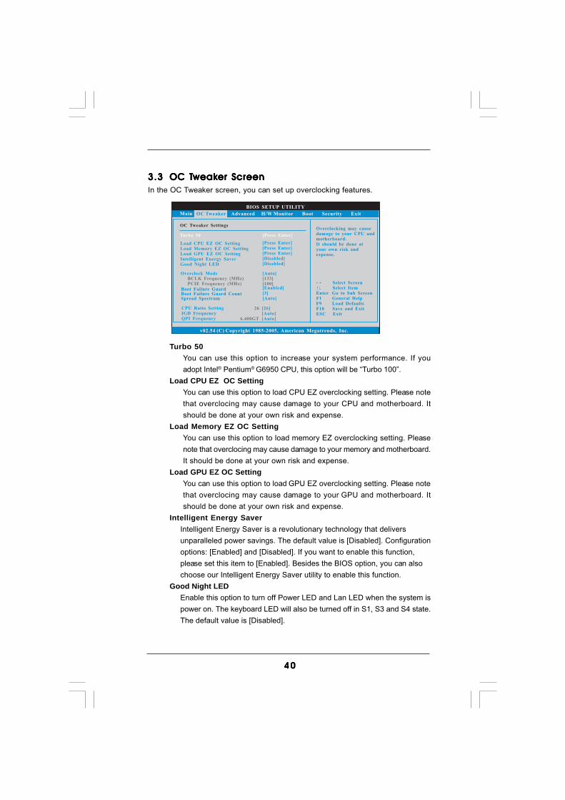
3.33.33.33.33.3 OC TOC TOC TOC TOC Tweakweakweakweakweaker Screener Screener Screener Screener ScreenIn the OC Tweaker screen, you can set up overclocking features.
BIOS SETUP UTILITY
Main Advanced H/W Monitor Boot Security Exit
Overclocking may causedamage to your CPU andmotherboard.It should be done atyour own risk andexpense.
Select ScreenSelect Item
Enter Go to Sub ScreenF1 General HelpF9 Load DefaultsF10 Save and ExitESC Exit
v02.54 (C) Copyright 1985-2005, American Megatrends, Inc.
OC Tweaker
OC Tweaker Settings
Turbo 50
BCLK Frequency (MHz)PCIE Frequency (MHz)
Overclock Mode[133][100]
[Auto]
Boot Failure Guard
Spread SpectrumBoot Failure Guard Count
[Enabled][3][Auto]
CPU Ratio SettingIGD FrequencyQPI Frequency
[26][Auto][Auto]
Load CPU EZ OC Setting
Intelligent Energy SaverGood Night LED
Load Memory EZ OC SettingLoad GPU EZ OC Setting
[Press Enter]
[Disabled][Disabled]
[Press Enter][Press Enter]
26
6.400GT
[Press Enter]
Turbo 50You can use this option to increase your system performance. If youadopt Intel® Pentium® G6950 CPU, this option will be “Turbo 100”.
Load CPU EZ OC SettingYou can use this option to load CPU EZ overclocking setting. Please notethat overclocing may cause damage to your CPU and motherboard. Itshould be done at your own risk and expense.
Load Memory EZ OC SettingYou can use this option to load memory EZ overclocking setting. Pleasenote that overclocing may cause damage to your memory and motherboard.It should be done at your own risk and expense.
Load GPU EZ OC SettingYou can use this option to load GPU EZ overclocking setting. Please notethat overclocing may cause damage to your GPU and motherboard. Itshould be done at your own risk and expense.
Intelligent Energy SaverIntelligent Energy Saver is a revolutionary technology that deliversunparalleled power savings. The default value is [Disabled]. Configurationoptions: [Enabled] and [Disabled]. If you want to enable this function,please set this item to [Enabled]. Besides the BIOS option, you can alsochoose our Intelligent Energy Saver utility to enable this function.
Good Night LEDEnable this option to turn off Power LED and Lan LED when the system ispower on. The keyboard LED will also be turned off in S1, S3 and S4 state.The default value is [Disabled].

4 14 14 14 14 1
Overclock ModeUse this to select Overclock Mode. Configuration options: [Auto], [Manual],[I.O.T.] and [Optimized]. The default value is [Auto]. If you select [Manual],Untied Overclocking function is enabled. Please refer to page 37 for thedetails of Untied Overclocking Technology. Therefore, you are allowed toadjust the Host frequency and PCIE frequency in the following two items.If you select [I.O.T.] (Intelligent Overclocking Technology), the system willautomatically enable the overclocking function when your CPU is heavyloaded.
BCLK Frequency (MHz)Use this option to adjust BCLK (Internal Base Clock) frequency.
PCIE Frequency (MHz)Use this option to adjust PCIE frequency.
Boot Failure GuardEnable or disable the feature of Boot Failure Guard.
Boot Failure Guard CountEnable or disable the feature of Boot Failure Guard Count.
Spread SpectrumThis item should always be [Auto] for better system stability.
CPU Ratio SettingIf the ratio status is unlocked, you will find this item appear to allow youchanging the ratio value of this motherboard.
IGD FrequencyUse this option to adjust IGD frequency.
QPI FrequencyUse this option to adjust QPI frequency.
DRAM FrequencyIf [Auto] is selected, the motherboard will detect the memory module(s)inserted and assigns appropriate frequency automatically.
4 24 24 24 24 2
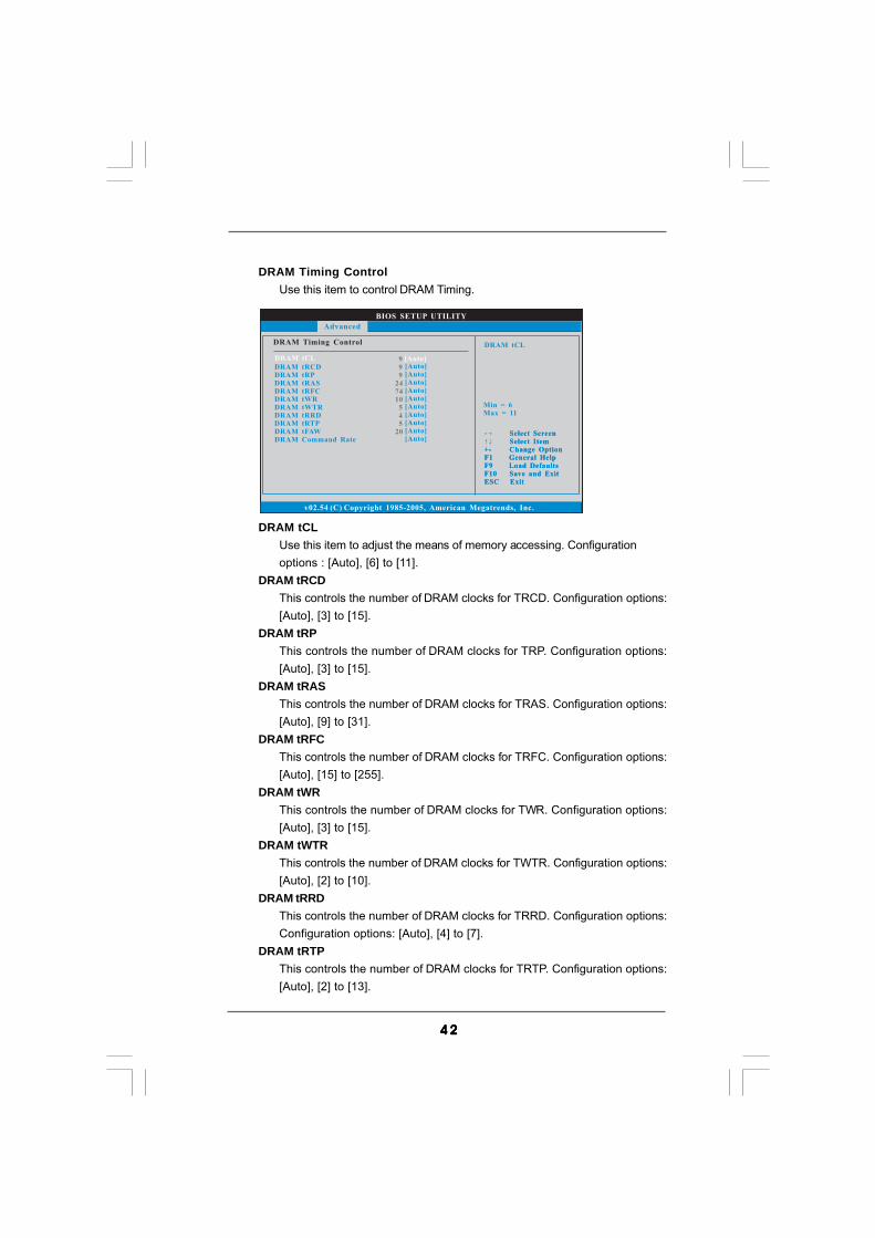
DRAM tCLUse this item to adjust the means of memory accessing. Configurationoptions : [Auto], [6] to [11].
DRAM tRCDThis controls the number of DRAM clocks for TRCD. Configuration options:[Auto], [3] to [15].
DRAM tRPThis controls the number of DRAM clocks for TRP. Configuration options:[Auto], [3] to [15].
DRAM tRASThis controls the number of DRAM clocks for TRAS. Configuration options:[Auto], [9] to [31].
DRAM tRFCThis controls the number of DRAM clocks for TRFC. Configuration options:[Auto], [15] to [255].
DRAM tWRThis controls the number of DRAM clocks for TWR. Configuration options:[Auto], [3] to [15].
DRAM tWTRThis controls the number of DRAM clocks for TWTR. Configuration options:[Auto], [2] to [10].
DRAM tRRDThis controls the number of DRAM clocks for TRRD. Configuration options:Configuration options: [Auto], [4] to [7].
DRAM tRTPThis controls the number of DRAM clocks for TRTP. Configuration options:[Auto], [2] to [13].
BIOS SETUP UTILITY
DRAM Timing Control
Select ScreenSelect Item
+- Change OptionF1 General HelpF9 Load DefaultsF10 Save and ExitESC Exit
v02.54 (C) Copyright 1985-2005, American Megatrends, Inc.
Advanced
Select ScreenSelect Item
+- Change OptionF1 General HelpF9 Load DefaultsF10 Save and ExitESC Exit
DRAM tCL
DRAM tCL [Auto]
DRAM tRCDDRAM tRPDRAM tRASDRAM tRFCDRAM tWRDRAM tWTRDRAM tRRDDRAM tRTPDRAM tFAWDRAM Command Rate
[Auto][Auto][Auto][Auto][Auto][Auto][Auto][Auto][Auto][Auto]
Min = 6Max = 11
999
247410
545
20
DRAM Timing ControlUse this item to control DRAM Timing.
4 34 34 34 34 3
DRAM tFAWThis controls the number of DRAM clocks for TFAW. Configuration options:[Auto], [1] to [63].
DRAM Command RateUse this item to adjust DRAM Command Rate. Configurationoptions : [1], [2] and [Auto].
ASRock VDroop ControlUse this to enable or disable ASRock VDroop control. Configuration options:[With VDroop] and [Without VDroop]. The default value is [With VDroop].
CPU VoltageUse this to select CPU Voltage. Configuration options: [Auto], [Manual] and[Overdrive Offset]. The default value is [Auto].
DRAM VoltageUse this to select DRAM Voltage. Configuration options: [Auto], [0.998V] to[2.008V]. The default value is [Auto].
VTT VoltageUse this to select VTT Voltage. Configuration options: [Auto], [0.814V] to[2.594V]. The default value is [Auto].
PCH VoltageUse this to select PCH Voltage. Configuration options: [Auto], [1.066V] to[1.488V]. The default value is [Auto].
CPU PLL VoltageUse this to select CPU PLL Voltage. Configuration options: [Auto], [1.812V]to [2.324V]. The default value is [Auto].
GFX VoltageUse this to select GFX Voltage. Configuration options: [Auto], [+0 mV] to[+300 mV]. The default value is [Auto].
IGD VIDUse this to select onboard VGA VID. Configuration options: [Auto],[0.8500V] to [1.4625V]. The default value is [Auto].
Would you like to save current setting user defaults?In this option, you are allowed to load and save three user defaultsaccording to your own requirements.

4 44 44 44 44 4
Setting wrong values in this section may causethe system to malfunction.
3.43.43.43.43.4 Advanced ScreenAdvanced ScreenAdvanced ScreenAdvanced ScreenAdvanced ScreenIn this section, you may set the configurations for the following items: CPU Configuration,Chipset Configuration, ACPI Configuration, Storage Configuration, PCIPnPConfiguration, SuperIO Configuration, and USB Configuration.
BIOS SETUP UTILITY
Main OC Tweaker H/W Monitor Boot Security Exit
Select ScreenSelect Item
Enter Go to Sub ScreenF1 General HelpF9 Load DefaultsF10 Save and ExitESC Exit
v02.54 (C) Copyright 1985-2005, American Megatrends, Inc.
Advanced
Advanced Settings
WARNING : Setting wrong values in below sectionsmay cause system to malfunction.
CPU Configuration
ACPI ConfigurationChipset Configuration
Storage ConfigurationPCIPnP ConfigurationSuperIO ConfigurationUSB Configuration
Options for CPU
BIOS Update Utility
ASRock Instant Flash
ASRock Instant FlashASRock Instant Flash is a BIOS flash utility embedded in Flash ROM. Thisconvenient BIOS update tool allows you to update system BIOS withoutentering operating systems first like MS-DOS or Windows®. Just launchthis tool and save the new BIOS file to your USB flash drive, floppy disk orhard drive, then you can update your BIOS only in a few clicks withoutpreparing an additional floppy diskette or other complicated flash utility.Please be noted that the USB flash drive or hard drive must use FAT32/16/12 file system. If you execute ASRock Instant Flash utility, the utility willshow the BIOS files and their respective information. Select the properBIOS file to update your BIOS, and reboot your system after BIOS updateprocess completes.

4 54 54 54 54 5
3.4.13.4.13.4.13.4.13.4.1 CPU ConfigurationCPU ConfigurationCPU ConfigurationCPU ConfigurationCPU Configuration
CPU Ratio SettingIf the ratio status is unlocked, you will find this item appear to allow youchanging the ratio value of this motherboard.
Enhance Halt StateAll processors support the Halt State (C1). The C1 state is supportedthrough the native processor instructions HLT and MWAIT and requires nohardware support from the chipset. In the C1 power state, the processormaintains the context of the system caches.
Intel (R) Virtualization TechWhen this option is set to [Enabled], a VMM (Virtual Machine Architecture)can utilize the additional hardware capabilities provided by VanderpoolTechnology. This option will be hidden if the installed CPU does not supportIntel (R) Virtualization Technology.
CPU Thermal ThrottlingYou may select [Enabled] to enable CPU internal thermal control mechanismto keep the CPU from overheated.
No-Excute Memory ProtectionNo-Execution (NX) Memory Protection Technology is an enhancement tothe IA-32 Intel Architecture. An IA-32 processor with “No Execute (NX)Memory Protection” can prevent data pages from being used by malicioussoftware to execute code. This option will be hidden if the current CPUdoes not support No-Excute Memory Protection.
Hyper Threading TechnologyTo enable this feature, it requires a computer system with an Intel® proces-sor that supports Hyper-Threading technology and an operating systemthat includes optimization for this technology, such as Microsoft® Win-dows® XP / VistaTM / 7. Set to [Enabled] if using Microsoft® Windows® XP /
BIOS SETUP UTILITY
Select ScreenSelect Item
+- Change OptionF1 General HelpF9 Load DefaultsF10 Save and ExitESC Exit
v02.54 (C) Copyright 1985-2005, American Megatrends, Inc.
Advanced
Select ScreenSelect Item
+- Change OptionF1 General HelpF9 Load DefaultsF10 Save and ExitESC Exit
Select the rationbetween CPU CoreClock and the FSBFrequency.
Enhanced Halt StateIntel (R) Virtualization TechCPU Thermal ThrottlingNo-Excute Memory ProtectionHyper Threading TechnologyActive Processor CoresA20MIntel (R) SpeedStep (tm) techIntel (R) C-STATE tech
[Disabled][Enabled][Enabled][Disabled][Enabled][All][Disabled][Enabled][Enabled]
CPU Ratio Setting [26]
Intel (R) Core (TM) i5 CPU 670 @ 3.47GHzFrequency :3.46GHzCache L1 :256 KBCache L2 :1024 KBCache L3 :4096 KBRatio Status:Unlocked (Min:09, Max:26)Ratio Actual Value:26
Configure advanded CPU settings
26

4 64 64 64 64 6
Intel (R) TurboMode techUse this item to enable or disable Intel (R) Turbo Boost Technology. Turbomode allows processor cores to run faster than marked frequency in specificcondition. The default value is [Enabled].
Intel (R) C-STATE tech.Intel (R) C-STATE tech. is achieved by making the power and thermal con-trol unit part of the core logic and not part of the chipset as before. Migrationof the power and thermal management flow into the processor allows usto use a hardware coordination mechanism in which each core can re-quest any C-state it wishes, thus allowing for individual core savings to bemaximized. The CPU C-state is determined and entered based on the low-est common denominator of both cores’ requests, portraying a single CPUentity to the chipset power management hardware and flows. Thus, soft-ware can manage each core independently, while the actual power man-agement adheres to the platform and CPU shared resource restrictions.
C State package limit settingThis item appears only when you set the item “Intel (R) C-STATE tech.” to[Enabled]. The selected option will programme into C State package limitregister. Configuration options: [Auto], [C3] and [C6]. The default value is[Auto].
Please note that enabling this function may reduce CPU voltage and lead to systemstability or compatibility issue with some power supplies. Please set this item to[Disable] if above issue occurs.
VistaTM / 7, or Linux kernel version 2.4.18 or higher. This option will behidden if the installed CPU does not support Hyper-Threading technology.
Active Processor CoresUse this item to select the number of cores to enable in each processorpackage. Configuration options: [All], [1] and [2]. The default value is [All].
A20MUse this item to enable or disable A20M. Legacy OS and AP may need A20Menabled. The default value is [Disabled].
Intel (R) SpeedStep(tm) tech.Intel (R) SpeedStep(tm) tech. is Intel’s new power saving technology. Proces-sor can switch between multiple frequency and voltage points to enable powersavings. The default value is [Enabled]. Configuration options: [Auto],[Enabled] and [Disabled]. If you install Windows® XP and select [Auto], youneed to set the “Power Schemes” as “Portable/Laptop” to enable this function.If you install Windows® VistaTM and want to enable this function, please setthis item to [Enabled]. This item will be hidden if the current CPU does notsupport Intel (R) SpeedStep(tm) tech..

4 74 74 74 74 7
BIOS SETUP UTILITY
Chipset Settings
Select ScreenSelect Item
+- Change OptionF1 General HelpF9 Load DefaultsF10 Save and ExitESC Exit
v02.54 (C) Copyright 1985-2005, American Megatrends, Inc.
Advanced
Select ScreenSelect Item
+- Change OptionF1 General HelpF9 Load DefaultsF10 Save and ExitESC Exit
Primary Graphics Adapter [PCI]
Share Memory
Onboard HD AudioFront Panel
Onboard HDMI HD AudioOnBoard Lan
Intel VT-d Configuration
DVMT Mode SelectDVMT/FIXED Memory
Onboard 1394
[Auto][DVMT Mode][Maximum DVMT][Auto]
[Enabled][Enabled][Enabled]
[Auto]
3.4.23.4.23.4.23.4.23.4.2 Chipset ConfigurationChipset ConfigurationChipset ConfigurationChipset ConfigurationChipset Configuration
Primary Graphics AdapterThis allows you to select [Onboard], [PCI] or [PCI Express] as the bootgraphic adapter priority. The default value is [PCI].
Share MemoryThis allows you to set share memory feature. The default value is [Auto].Configuration options: [Auto], [32MB], [64MB], [128MB] and [256MB].
DVMT Mode SelectUse this option to adjust DVMT mode. The default value is [DVMT Mode].DVMT (Dynamic Video Memory Technology) is an architecture that offersbreakthrough performance for the motherboard through efficient memoryutilization. In DVMT mode, the graphics driver allocates memory as neededfor running graphics applications and is cooperatively using this memorywith other system components. This item will not be used under Windows®
VistaTM / 7 OS because the driver will intelligently detect physical memoryavailable and allocate necessary video memory.
DVMT/FIXED MemoryYou are allowed to adjust the shared memory size in this item if you setDVMT Mode Select as [DVMT Mode]. Configuration options: [128MB], [256MB]and [Maximum DVMT]. The option [Maximum DVMT] only appears when youadopt the memory module with 1024MB or above.
Onboard HD AudioSelect [Auto], [Enabled] or [Disabled] for the onboard HD Audio feature. Ifyou select [Auto], the onboard HD Audio will be disabled when PCI SoundCard is plugged.
Front PanelSelect [Auto], [Enabled] or [Disabled] for the onboard HD Audio Front Panel.
Onboard HDMI HD AudioThis allows you to enable or disable the “Onboard HDMI HD Audio” feature.

4 84 84 84 84 8
OnBoard LanThis allows you to enable or disable the “OnBoard Lan” feature.
Onboard 1394This allows you to enable or disable the “Onboard 1394” feature.
Intel VT-d ConfigurationUse this to enable or disable Intel® VT-d technology (Intel® VirtualizationTechnology for Directed I/O). The default value of this feature is [Disabled].

4 94 94 94 94 9
BIOS SETUP UTILITY
ACPI Configuration Select auto-detect ordisable the STRfeature.
Select ScreenSelect Item
+- Change OptionF1 General HelpF9 Load DefaultsF10 Save and ExitESC Exit
v02.54 (C) Copyright 1985-2005, American Megatrends, Inc.
Advanced
Suspend To RAM
Check Ready Bit
Restore on AC/Power LossRing-In Power OnPCI Devices Power OnPS / 2 Keyboard Power OnRTC Alarm Power On
ACPI HPET Table
[Auto][Enabled]
[Power Off][Disabled][Disabled][Disabled][Disabled]
[Disabled]
3.4.33.4.33.4.33.4.33.4.3 ACPI ConfigurationACPI ConfigurationACPI ConfigurationACPI ConfigurationACPI Configuration
Suspend to RAMUse this item to select whether to auto-detect or disable the Suspend-to-RAM feature. Select [Auto] will enable this feature if the OS supports it.
Check Ready BitUse this item to enable or disable the feature Check Ready Bit.
Restore on AC/Power LossThis allows you to set the power state after an unexpected AC/powerloss. If [Power Off] is selected, the AC/power remains off when the powerrecovers. If [Power On] is selected, the AC/power resumes and thesystem starts to boot up when the power recovers.
Ring-In Power OnUse this item to enable or disable Ring-In signals to turn on the system fromthe power-soft-off mode.
PCI Devices Power OnUse this item to enable or disable PCI devices to turn on the system from thepower-soft-off mode.
PS/2 Keyboard Power OnUse this item to enable or disable PS/2 keyboard to turn on the system fromthe power-soft-off mode.
RTC Alarm Power OnUse this item to enable or disable RTC (Real Time Clock) to power on thesystem.
ACPI HPET TableUse this item to enable or disable ACPI HPET Table. The default value is[Disabled]. Please set this option to [Enabled] if you plan to use thismotherboard to submit Windows® VistaTM certification.

5 05 05 05 05 0
BIOS SETUP UTILITY
Storage Configuration
v02.54 (C) Copyright 1985-2003, American Megatrends, Inc.
Advanced
SATA Operation Mode
SATAII_0SATAII_1SATAII_2SATAII_3SATAII_4SATAII_5Marvell SATA3_1Marvell SATA3_2/eSATA3_1
[IDE]
[Hard Disk][Not Detected][Not Detected][Not Detected][Not Detected][Not Detected][Not Detected][Not Detected]
Select ScreenSelect Item
+- Change OptionF1 General HelpF9 Load DefaultsF10 Save and ExitESC Exit
Select ScreenSelect Item
+- Change OptionF1 General HelpF9 Load DefaultsF10 Save and ExitESC Exit
SATAII 1,2,3,4 ConfigurationSATAII 5,6 Configuration
[Compatible][Enhanced][IDE][Auto]
IDEAHCIDisabled
Options
Marvell SATA3 Operation ModeCompatible Mode
3.4.43.4.43.4.43.4.43.4.4 Storage ConfigurationStorage ConfigurationStorage ConfigurationStorage ConfigurationStorage Configuration
SATA Operation ModeUse this to select SATA Operation Mode. Configuration options: [IDE], [AHCI]and [Disabled]. The default value is [IDE].If you select [IDE] mode, the options “SATAII 1,2,3,4 Configuration” and“SATAII 5,6 Configuration” will appear.If you select [AHCI] mode, the options “Hot Plug” and “Link Power Manage-ment” will appear.
AHCI (Advanced Host Controller Interface) supports NCQ and othernew features that will improve SATA disk performance but IDEmode does not have these advantages.
Marvell SATA3 Operation ModeUse this item to select Marvell SATA3 operation mode. Configurationmode: [IDE] and [AHCI]. The default value is [IDE].
Compatible ModeUse this item to select Marvell SATA3 compatible mode. The default valueis [Auto].

5 15 15 15 15 1
[CD/DVD]: This is used for IDE CD/DVD drives.[ARMD]: This is used for IDE ARMD (ATAPI Removable Media Device),
such as MO.LBA/Large Mode
Use this item to select the LBA/Large mode for a hard disk > 512 MB underDOS and Windows; for Netware and UNIX user, select [Disabled] todisable the LBA/Large mode.
Block (Multi-Sector Transfer)The default value of this item is [Auto]. If this feature is enabled, it will enhancehard disk performance by reading or writing more data during each transfer.
PIO ModeUse this item to set the PIO mode to enhance hard disk performance byoptimizing the hard disk timing.
DMA ModeDMA capability allows the improved transfer-speed and data-integrity forcompatible IDE devices.
TYPEUse this item to configure the type of the IDE device that you specify. Configu-ration options: [Not Installed], [Auto], [CD/DVD], and [ARMD].[Not Installed]: Select [Not Installed] to disable the use of IDE device.[Auto]: Select [Auto] to automatically detect the hard disk drive.
After selecting the hard disk information into BIOS, use a diskutility, such as FDISK, to partition and format the new IDE harddisk drives. This is necessary so that you can write or read datafrom the hard disk. Make sure to set the partition of the PrimaryIDE hard disk drives to active.
BIOS SETUP UTILITY
SATAII 1 Master Select the typeof device connectedto the system.
Select ScreenSelect Item
+- Change OptionF1 General HelpF9 Load DefaultsF10 Save and ExitESC Exit
v02.54 (C) Copyright 1985-2005, American Megatrends, Inc.
Advanced
Type
LBA/Large ModeBlock (Multi-Sector Transfer)PIO ModeDMA ModeS . M . A . R . T .32Bit Data Transfer
[Auto]
[Auto][Auto][Auto][Auto][Disabled][Enabled]
DeviceVendorSizeLBA ModeBlock ModePIO ModeAsync DMAUltra DMAS.M.A.R.T.
:Hard Disk:ST340014A:40.0 GB:Supported:16Sectors:4:MultiWord DMA-2:Ultra DMA-5:Supported

5 25 25 25 25 2
BIOS SETUP UTILITY
Advanced PCI / PnP Settings Value in units of PCIclocks for PCI devicelatency timerregister.
Select ScreenSelect Item
+- Change OptionF1 General HelpF9 Load DefaultsF10 Save and ExitESC Exit
v02.54 (C) Copyright 1985-2005, American Megatrends, Inc.
PCI Latency TimerPCI IDE BusMaster
[64][Enabled]
Advanced
3.4.53.4.53.4.53.4.53.4.5 PCIPnP ConfigurationPCIPnP ConfigurationPCIPnP ConfigurationPCIPnP ConfigurationPCIPnP Configuration
PCI Latency TimerThe default value is 32. It is recommended to keep the default value unlessthe installed PCI expansion cards’ specifications require other settings.
PCI IDE BusMasterUse this item to enable or disable the PCI IDE BusMaster feature.
S.M.A.R.T.Use this item to enable or disable the S.M.A.R.T. (Self-Monitoring, Analysis,and Reporting Technology) feature. Configuration options: [Disabled], [Auto],[Enabled].
32-Bit Data TransferUse this item to enable 32-bit access to maximize the IDE hard disk datatransfer rate.
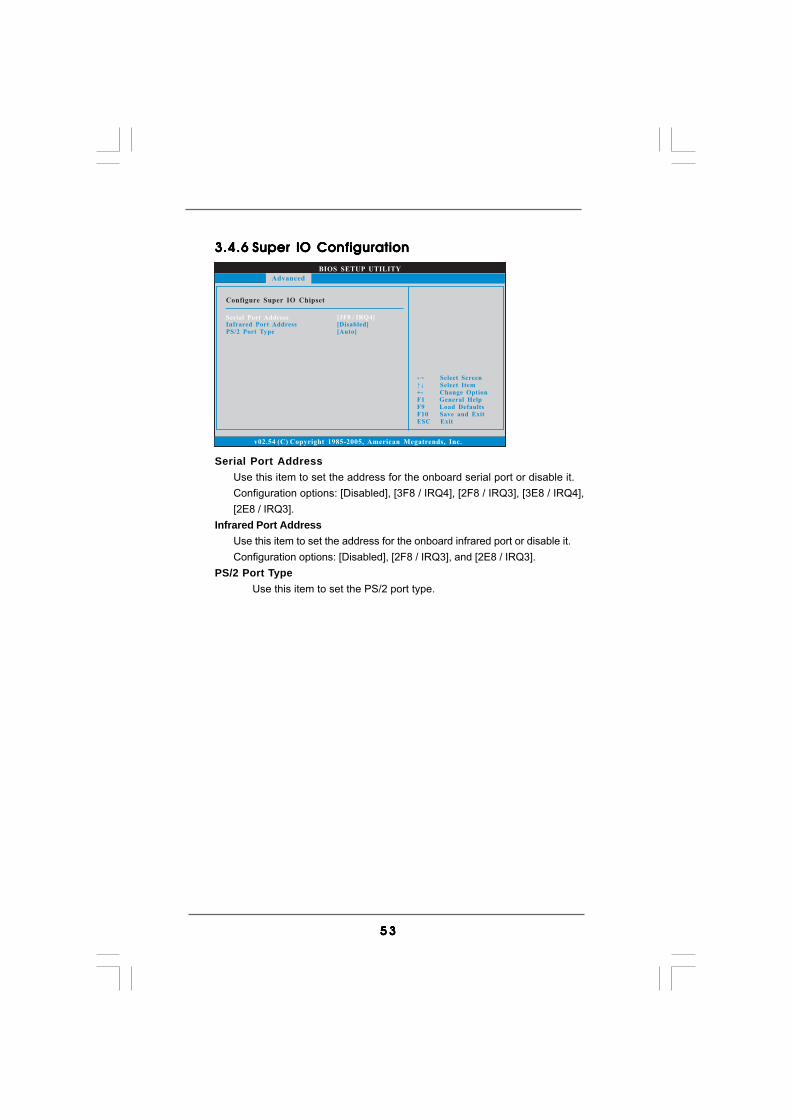
5 35 35 35 35 3
3.4.63.4.63.4.63.4.63.4.6 Super IO ConfigurationSuper IO ConfigurationSuper IO ConfigurationSuper IO ConfigurationSuper IO Configuration
Serial Port AddressUse this item to set the address for the onboard serial port or disable it.Configuration options: [Disabled], [3F8 / IRQ4], [2F8 / IRQ3], [3E8 / IRQ4],[2E8 / IRQ3].
Infrared Port AddressUse this item to set the address for the onboard infrared port or disable it.Configuration options: [Disabled], [2F8 / IRQ3], and [2E8 / IRQ3].
PS/2 Port TypeUse this item to set the PS/2 port type.
BIOS SETUP UTILITY
Configure Super IO Chipset
Select ScreenSelect Item
+- Change OptionF1 General HelpF9 Load DefaultsF10 Save and ExitESC Exit
v02.54 (C) Copyright 1985-2005, American Megatrends, Inc.
Advanced
Serial Port AddressInfrared Port AddressPS/2 Port Type
[3F8 / IRQ4][Disabled][Auto]
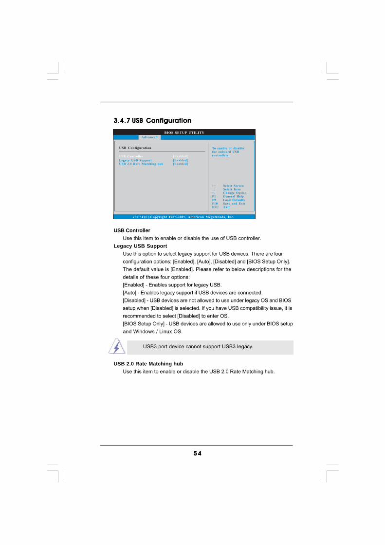
5 45 45 45 45 4
3.4.73.4.73.4.73.4.73.4.7 USB ConfigurationUSB ConfigurationUSB ConfigurationUSB ConfigurationUSB Configuration
USB ControllerUse this item to enable or disable the use of USB controller.
Legacy USB SupportUse this option to select legacy support for USB devices. There are fourconfiguration options: [Enabled], [Auto], [Disabled] and [BIOS Setup Only].The default value is [Enabled]. Please refer to below descriptions for thedetails of these four options:[Enabled] - Enables support for legacy USB.[Auto] - Enables legacy support if USB devices are connected.[Disabled] - USB devices are not allowed to use under legacy OS and BIOSsetup when [Disabled] is selected. If you have USB compatibility issue, it isrecommended to select [Disabled] to enter OS.[BIOS Setup Only] - USB devices are allowed to use only under BIOS setupand Windows / Linux OS.
BIOS SETUP UTILITY
USB Configuration To enable or disablethe onboard USBcontrollers.
Select ScreenSelect Item
+- Change OptionF1 General HelpF9 Load DefaultsF10 Save and ExitESC Exit
v02.54 (C) Copyright 1985-2005, American Megatrends, Inc.
Advanced
USB Controller
Legacy USB SupportUSB 2.0 Rate Matching hub
[Enabled]
[Enabled][Enabled]
USB 2.0 Rate Matching hubUse this item to enable or disable the USB 2.0 Rate Matching hub.
USB3 port device cannot support USB3 legacy.

5 55 55 55 55 5
BIOS SETUP UTILITY
Hardware Health Event Monitoring
Select ScreenSelect Item
F1 General HelpF9 Load DefaultsF10 Save and ExitESC Exit
v02.54 (C) Copyright 1985-2003, American Megatrends, Inc.
CPU TemperatureM / B Temperature
Vcore+ 3.30V+ 12.0V+ 5.00V
CPU Fan SpeedChassis Fan1 SpeedChassis Fan2 Speed
Power Fan SpeedChassis Fan3 Speed
: 37 C / 98 F
: 1.152V: 3.312V: 11.968V: 5.080V
: 31 C / 87 F
: N/A: N/A: N/A: N/A: N/A
Main OC Tweaker Advanced Boot Security ExitH/W Monitor
CPU Fan SettingChassis Fan 1 SettingChassis Fan 2 SettingChassis Fan 3 Setting
3.53 .53 .53 .53 .5 Hardware Health Event Monitoring ScreenHardware Health Event Monitoring ScreenHardware Health Event Monitoring ScreenHardware Health Event Monitoring ScreenHardware Health Event Monitoring ScreenIn this section, it allows you to monitor the status of the hardware on your system,including the parameters of the CPU temperature, motherboard temperature, CPU fanspeed, chassis fan speed, and the critical voltage.
CPU Fan SettingThis allows you to set the CPU fan speed. Configuration options: [Full On]and [Automatic mode]. The default is value [Full On].
Chassis Fan 1 SettingThis allows you to set the chassis fan 1 speed. Configuration options:[Full On] and [Manual mode]. The default is value [Full On].
Chassis Fan 2 SettingThis allows you to set the chassis fan 2 speed. Configuration options:[Level 1] to [Level 4]. The default is value [Level 4].
Chassis Fan 3 SettingThis allows you to set the chassis fan 3 speed. Configuration options:[Full On] and [Manual mode]. The default is value [Full On].
Case Open FeatureThis allows you to enable or disable case open detection feature. Thedefault is value [Enabled].
Clear StatusThis option appears only when the case open has been detected. Use thisoption to keep or clear the record of previous chassis intrusion status.

5 65 65 65 65 6
3.6.13.6.13.6.13.6.13.6.1 Boot Settings ConfigurationBoot Settings ConfigurationBoot Settings ConfigurationBoot Settings ConfigurationBoot Settings Configuration
Full Screen Logo Use this item to enable or disable OEM Logo. The default value is [Enabled].AddOn ROM Display Use this option to adjust AddOn ROM Display. If you enable the option “Full Screen Logo” but you want to see the AddOn ROM information when the system boots, please select [Enabled]. Configuration options: [Enabled] and [Disabled]. The default value is [Enabled].
BIOS SETUP UTILITY
Boot Settings ConfigurationDisabled: Displaysnormal POST messages.Enabled: Displays OEMLogo instead of POSTmessages.
Select ScreenSelect Item
+ - Change OptionF1 General HelpF9 Load DefaultsF10 Save and ExitESC Exit
v02.54 (C) Copyright 1985-2003, American Megatrends, Inc.
Boot
AddOn ROM DisplayBoot Logo
Boot From Onboard LANBootup Num-Lock
[Enabled][Auto][Disabled][On]
Full Screen Logo [Enabled]
3.63 .63 .63 .63 .6 Boot ScreenBoot ScreenBoot ScreenBoot ScreenBoot ScreenIn this section, it will display the available devices on your system for you to configurethe boot settings and the boot priority.
BIOS SETUP UTILITY
Main OC Tweaker Advanced H/W Monitor Security Exit
Boot SettingsConfigure Settingsduring System Boot.
Select ScreenSelect Item
Enter Go to Sub ScreenF1 General HelpF9 Load DefaultsF10 Save and ExitESC Exit
v02.54 (C) Copyright 1985-2005, American Megatrends, Inc.
Boot
Boot Settings Configuration
1st Boot Device2nd Boot Device3rd Boot Device
Hard Disk DrivesRemovable DrivesCD/DVD Drives
[1st Floppy Device][HDD: PM - HDS722580VL][CD / DVD: 3S - CD - ROM C]

5 75 75 75 75 7
BIOS SETUP UTILITY
Main OC Tweaker Advanced H/W Monitor Boot Exit
Install or Change thepassword.
Select ScreenSelect Item
Enter ChangeF1 General Help
F10 Save and ExitESC Exit
F9 Load Defaults
v02.54 (C) Copyright 1985-2005, American Megatrends, Inc.
Security
Change Supervisor Password
Change User Password
Security Settings
Supervisor Password : Not InstalledUser Password : Not Installed
Boot Logo Use this option to select logo in POST screen. This option only appears when you enable the option “Full Screen Logo”. Configuration options: [Auto], [EuP], [Scenery] and [ASRock]. The default value is [Auto].Boot From Onboard LAN
Use this item to enable or disable the Boot From Onboard LAN feature.Boot Up Num-Lock
If this item is set to [On], it will automatically activate the Numeric Lockfunction after boot-up.
3.73 .73 .73 .73 .7 Security ScreenSecurity ScreenSecurity ScreenSecurity ScreenSecurity ScreenIn this section, you may set or change the supervisor/user password for the system. Forthe user password, you may also clear it.

5 85 85 85 85 8
BIOS SETUP UTILITY
Main OC Tweaker Advanced H/W Monitor Boot Security
Exit system setupafter saving thechanges.
F10 key can be usedfor this operation.
Select ScreenSelect Item
Enter Go to Sub ScreenF1 General Help
F10 Save and ExitESC Exit
F9 Load Defaults
v02.54 (C) Copyright 1985-2005, American Megatrends, Inc.
Exit
Save Changes and Exit
Discard Changes and ExitDiscard Changes
Load BIOS DefaultsLoad Performance Setup Default (IDE/SATA)Load Performance Setup AHCI ModeLoad Power Saving Setup Default
Exit Options
3.83.83.83.83.8 Exit ScreenExit ScreenExit ScreenExit ScreenExit Screen
Save Changes and ExitWhen you select this option, it will pop-out the following message, “Saveconfiguration changes and exit setup?” Select [OK] to save the changes andexit the BIOS SETUP UTILITY.
Discard Changes and ExitWhen you select this option, it will pop-out the following message, “Discardchanges and exit setup?” Select [OK] to exit the BIOS SETUP UTILITY with-out saving any changes.
Discard ChangesWhen you select this option, it will pop-out the following message, “Discardchanges?” Select [OK] to discard all changes.
Load BIOS DefaultsLoad BIOS default values for all the setup questions. F9 key can be usedfor this operation.
Load Performance Setup Default (IDE/SATA)This performance setup default may not be compatible with all systemconfigurations. If system boot failure occurs after loading, please resumeoptimal default settings. F5 key can be used for this operation.
Load Performance Setup AHCI ModeThis performance setup AHCI mode may not be compatible with all systemconfigurations. If system boot failure occurs after loading, please resumeoptimal default settings. F3 key can be used for this operation.
Load Power Saving Setup DefaultLoad power saving setup default. F6 key can be used for this operation.

5 95 95 95 95 9
Chapter 4: SofChapter 4: SofChapter 4: SofChapter 4: SofChapter 4: Software Supportware Supportware Supportware Supportware Supporttttt4.14.14.14.14.1 Install Operating SystemInstall Operating SystemInstall Operating SystemInstall Operating SystemInstall Operating System
This motherboard supports various Microsoft® Windows® operating systems: 7 /7 64-bit / VistaTM / VistaTM 64-bit / XP / XP 64-bit. Because motherboard settings andhardware options vary, use the setup procedures in this chapter for general refer-ence only. Refer to your OS documentation for more information.
4.24 .24 .24 .24 .2 Support CD InformationSupport CD InformationSupport CD InformationSupport CD InformationSupport CD Information
The Support CD that came with the motherboard contains necessary drivers anduseful utilities that enhance the motherboard features.
4.2.14.2.14.2.14.2.14.2.1 Running The Support CDRunning The Support CDRunning The Support CDRunning The Support CDRunning The Support CD
To begin using the support CD, insert the CD into your CD-ROM drive. The CDautomatically displays the Main Menu if “AUTORUN” is enabled in your computer.If the Main Menu did not appear automatically, locate and double click on thefile “ASSETUP.EXE” from the BIN folder in the Support CD to display the menus.
4.2.24.2.24.2.24.2.24.2.2 Drivers MenuDrivers MenuDrivers MenuDrivers MenuDrivers Menu
The Drivers Menu shows the available devices drivers if the system detectsinstalled devices. Please install the necessary drivers to activate the devices.
4.2.34.2.34.2.34.2.34.2.3 Uti l i t ies MenuUti l i t ies MenuUti l i t ies MenuUti l i t ies MenuUti l i t ies Menu
The Utilities Menu shows the applications software that the motherboardsupports. Click on a specific item then follow the installation wizard to install it.
4.2.44.2.44.2.44.2.44.2.4 Contact Informat ionContact Informat ionContact Informat ionContact Informat ionContact Informat ion
If you need to contact ASRock or want to know more about ASRock, welcometo visit ASRock’s website at http://www.asrock.com; or you may contact yourdealer for further information.