H1: Vernier Hook and Point Gauges PDF - DISCOVE Rdiscoverarmfield.com/media/transfer/doc/h.pdf ·...
16
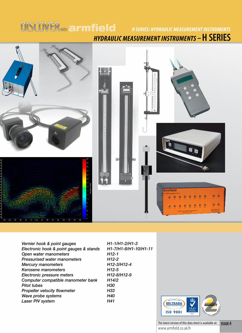
HYDRAULIC MEASUREMENT INSTRUMENTS – H SERIES H SERIES: HYDRAULIC MEASUREMENT INSTRUMENTS ISSUE 4 The latest version of this data sheet is available at: www.armfield.co.uk/h 2 - Y R W A R R A N T Y O N A L L A R M F IE L D P R O D U C T S <EXTENDED> WARRANTY 2 years Vernier hook & point gauges H1-1/H1-2/H1-3 Electronic hook & point gauges & stands H1-7/H1-8/H1-10/H1-11 Open water manometers H12-1 Pressurised water manometers H12-2 Mercury manometers H12-3/H12-4 Kerosene manometers H12-5 Electronic pressure meters H12-8/H12-9 Computer compatible manometer bank H14/2 Pitot tubes H30 Propeller velocity flowmeter H33 Wave probe systems H40 Laser PIV system H41 WITH DISCOVER
Transcript of H1: Vernier Hook and Point Gauges PDF - DISCOVE Rdiscoverarmfield.com/media/transfer/doc/h.pdf ·...
HYDRAULIC MEASUREMENT INSTRUMENTS – H SerieSH SERIES: HYDRAULIC MEASUREMENT INSTRUMENTS
iSSue 4The latest version of this data sheet is available at:
www.armfield.co.uk/h
2 -YR WARRANTY ON ALL ARMFIELD P
RODU
CTS
<EXTENDED> WARRANTY
2 years
Vernier hook & point gauges H1-1/H1-2/H1-3 Electronic hook & point gauges & stands H1-7/H1-8/H1-10/H1-11 Open water manometers H12-1 Pressurised water manometers H12-2 Mercury manometers H12-3/H12-4 Kerosene manometers H12-5 Electronic pressure meters H12-8/H12-9 Computer compatible manometer bank H14/2 Pitot tubes H30 Propeller velocity flowmeter H33 Wave probe systems H40 Laser PIV system H41
WITH DISCOVER
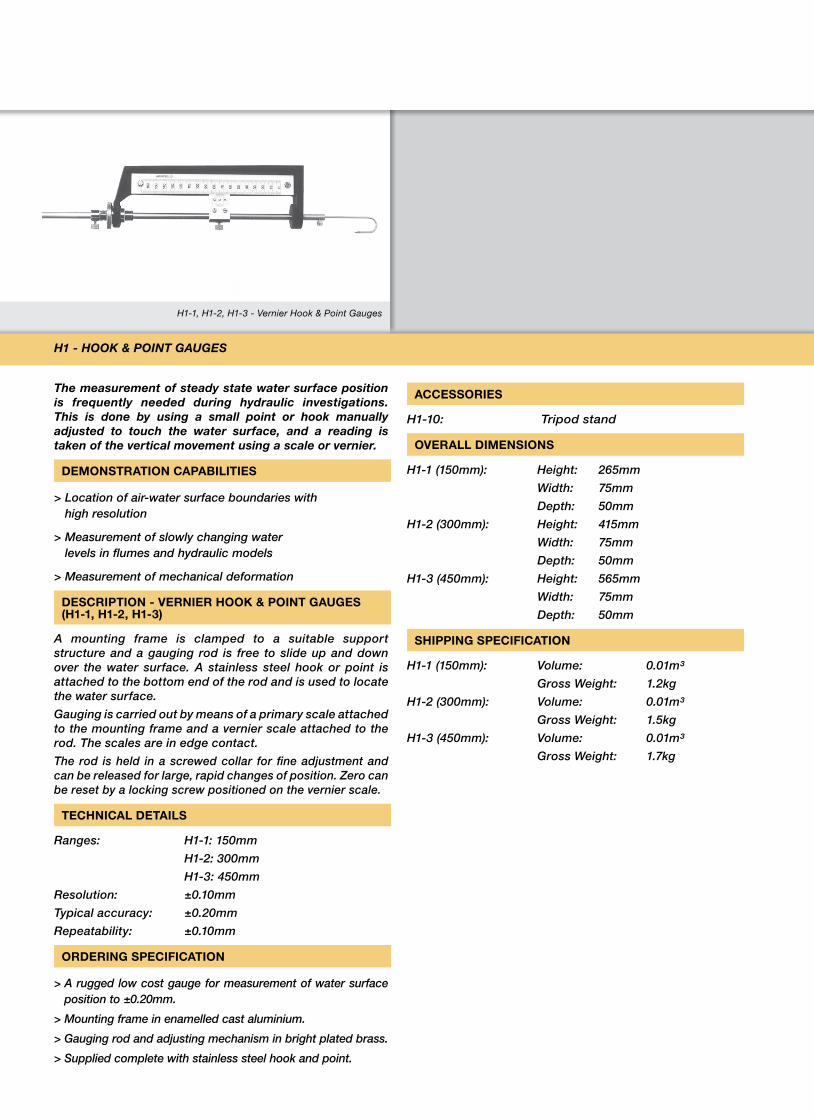
H1-1, H1-2, H1-3 - Vernier Hook & Point Gauges
The measurement of steady state water surface position is frequently needed during hydraulic investigations. This is done by using a small point or hook manually adjusted to touch the water surface, and a reading is taken of the vertical movement using a scale or vernier.
DEMONSTRATION CAPABILITIES
> Location of air-water surface boundaries with high resolution
> Measurement of slowly changing water levels in flumes and hydraulic models
> Measurement of mechanical deformation
DESCRIPTION - VERNIER HOOK & POINT GAUGES (H1-1, H1-2, H1-3)
A mounting frame is clamped to a suitable support structure and a gauging rod is free to slide up and down over the water surface. A stainless steel hook or point is attached to the bottom end of the rod and is used to locate the water surface.
Gauging is carried out by means of a primary scale attached to the mounting frame and a vernier scale attached to the rod. The scales are in edge contact.
The rod is held in a screwed collar for fine adjustment and can be released for large, rapid changes of position. Zero can be reset by a locking screw positioned on the vernier scale.
TECHNICAL DETAILS
Ranges: H1-1: 150mm
H1-2: 300mm
H1-3: 450mm
Resolution: ±0.10mm
Typical accuracy: ±0.20mm
Repeatability: ±0.10mm
ORDERING SPECIFICATION
> A rugged low cost gauge for measurement of water surface position to ±0.20mm.
> Mounting frame in enamelled cast aluminium.
> Gauging rod and adjusting mechanism in bright plated brass.
> Supplied complete with stainless steel hook and point.
ACCESSORIES
H1-10: Tripod stand
OVERALL DIMENSIONS
H1-1 (150mm): Height: 265mm
Width: 75mm
Depth: 50mm
H1-2 (300mm): Height: 415mm
Width: 75mm
Depth: 50mm
H1-3 (450mm): Height: 565mm
Width: 75mm
Depth: 50mm
SHIPPING SPECIFICATION
H1-1 (150mm): Volume: 0.01m³
Gross Weight: 1.2kg
H1-2 (300mm): Volume: 0.01m³
Gross Weight: 1.5kg
H1-3 (450mm): Volume: 0.01m³
Gross Weight: 1.7kg
H1 - Hook & PoinT GauGes
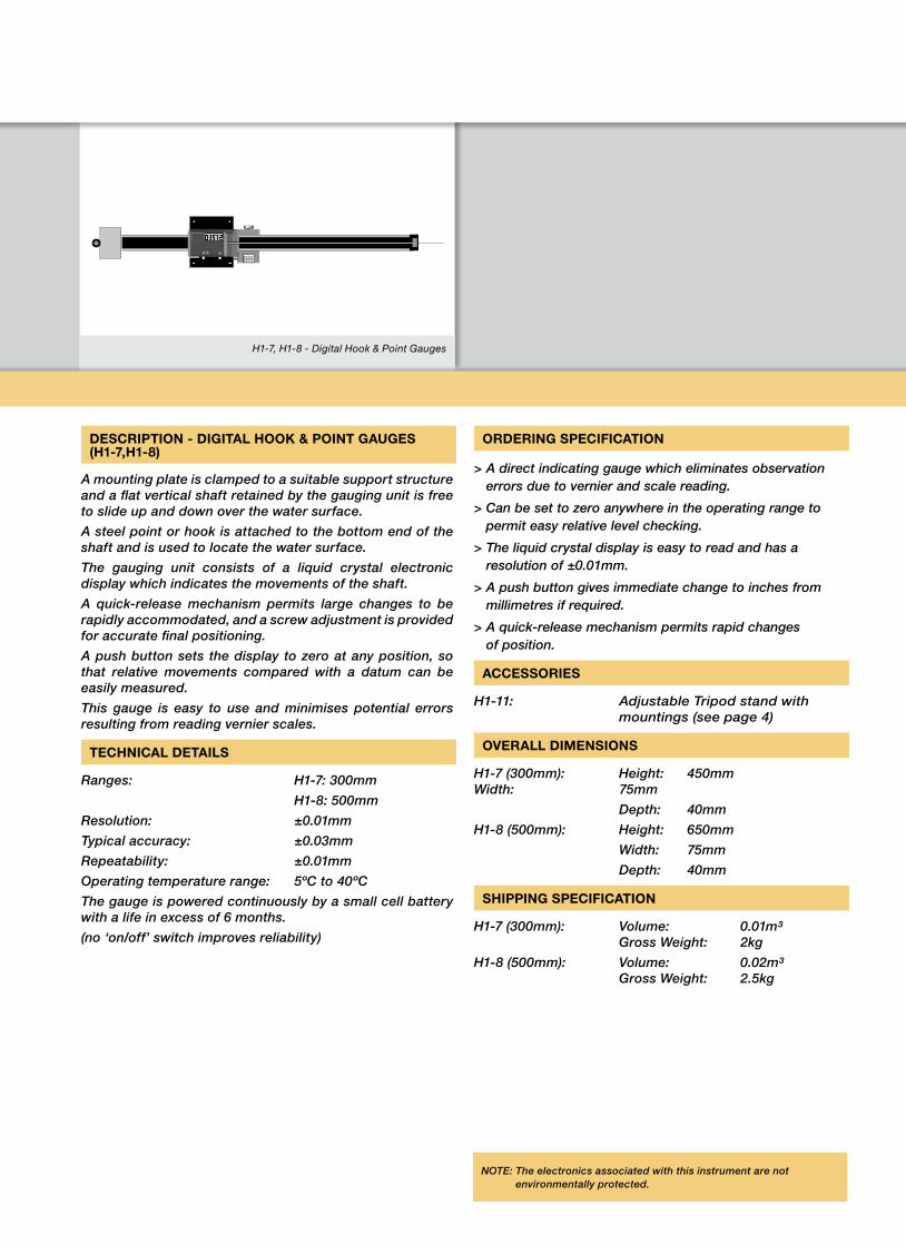
H1-7, H1-8 - Digital Hook & Point Gauges
NOTE: The electronics associated with this instrument are not environmentally protected.
DESCRIPTION - DIGITAL HOOK & POINT GAUGES (H1-7,H1-8)
A mounting plate is clamped to a suitable support structure and a flat vertical shaft retained by the gauging unit is free to slide up and down over the water surface.
A steel point or hook is attached to the bottom end of the shaft and is used to locate the water surface.
The gauging unit consists of a liquid crystal electronic display which indicates the movements of the shaft.
A quick-release mechanism permits large changes to be rapidly accommodated, and a screw adjustment is provided for accurate final positioning.
A push button sets the display to zero at any position, so that relative movements compared with a datum can be easily measured.
This gauge is easy to use and minimises potential errors resulting from reading vernier scales.
TECHNICAL DETAILS
Ranges: H1-7: 300mm
H1-8: 500mm
Resolution: ±0.01mm
Typical accuracy: ±0.03mm
Repeatability: ±0.01mm
Operating temperature range: 5ºC to 40ºC
The gauge is powered continuously by a small cell battery with a life in excess of 6 months.
(no ‘on/off’ switch improves reliability)
ORDERING SPECIFICATION
> A direct indicating gauge which eliminates observation errors due to vernier and scale reading.
> Can be set to zero anywhere in the operating range to permit easy relative level checking.
> The liquid crystal display is easy to read and has a resolution of ±0.01mm.
> A push button gives immediate change to inches from millimetres if required.
> A quick-release mechanism permits rapid changes of position.
ACCESSORIES
H1-11: Adjustable Tripod stand with mountings (see page 4)
OVERALL DIMENSIONS
H1-7 (300mm): Height: 450mm Width: 75mm
Depth: 40mm
H1-8 (500mm): Height: 650mm
Width: 75mm
Depth: 40mm
SHIPPING SPECIFICATION
H1-7 (300mm): Volume: 0.01m³ Gross Weight: 2kg
H1-8 (500mm): Volume: 0.02m³ Gross Weight: 2.5kg
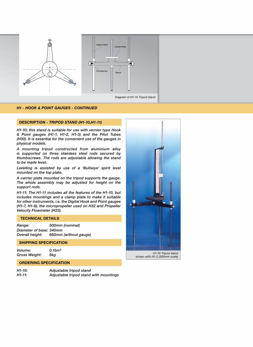
Diagram of H1-10 Tripod stand
Support RodCarrier Plate
TripodThumbscrew
DESCRIPTION - TRiPoD sTanD (H1-10,H1-11)
H1-10: this stand is suitable for use with vernier type Hook & Point gauges (H1-1, H1-2, H1-3) and the Pitot Tubes (H30). It is essential for the convenient use of the gauges in physical models.
A mounting tripod constructed from aluminium alloy is supported on three stainless steel rods secured by thumbscrews. The rods are adjustable allowing the stand to be made level.
Levelling is assisted by use of a ‘Bullseye’ spirit level mounted on the top plate.
A carrier plate mounted on the tripod supports the gauge. The whole assembly may be adjusted for height on the support rods.
H1-11: The H1-11 includes all the features of the H1-10, but includes mountings and a clamp plate to make it suitable for other instruments, i.e. the Digital Hook and Point gauges (H1-7, H1-8), the micropropeller used on H32 and Propeller Velocity Flowmeter (H33).
TECHNICAL DETAILS
Range: 500mm (nominal)Diameter of base: 340mm Overall height: 660mm (without gauge)
SHIPPING SPECIFICATION
Volume: 0.15m³ Gross Weight: 6kg
ORDERING SPECIFICATION
H1-10: Adjustable tripod stand H1-11: Adjustable tripod stand with mountings
H1 - Hook & PoinT GauGes - conTinueD
H1-10 Tripod stand shown with H1-2 (300mm scale)
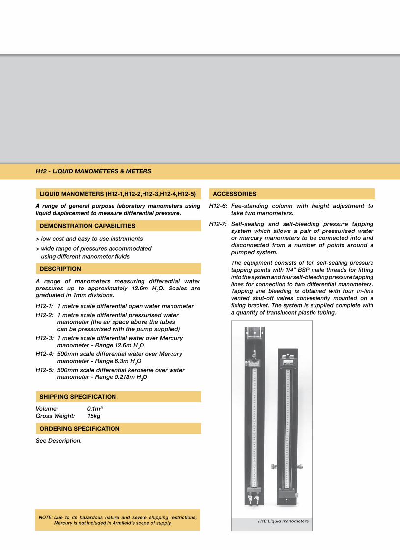
LIQUID MANOMETERS (H12-1,H12-2,H12-3,H12-4,H12-5)
a range of general purpose laboratory manometers using liquid displacement to measure differential pressure.
DEMONSTRATION CAPABILITIES
> low cost and easy to use instruments
> wide range of pressures accommodated using different manometer fluids
DESCRIPTION
A range of manometers measuring differential water pressures up to approximately 12.6m H2O. Scales are graduated in 1mm divisions.
H12-1: 1 metre scale differential open water manometer
H12-2: 1 metre scale differential pressurised water manometer (the air space above the tubes can be pressurised with the pump supplied)
H12-3: 1 metre scale differential water over Mercury manometer - Range 12.6m H2O
H12-4: 500mm scale differential water over Mercury manometer - Range 6.3m H2O
H12-5: 500mm scale differential kerosene over water manometer - Range 0.213m H2O
SHIPPING SPECIFICATION
Volume: 0.1m³ Gross Weight: 15kg
ORDERING SPECIFICATION
See Description.
ACCESSORIES
H12-6: Fee-standing column with height adjustment to take two manometers.
H12-7: Self-sealing and self-bleeding pressure tapping system which allows a pair of pressurised water or mercury manometers to be connected into and disconnected from a number of points around a pumped system.
The equipment consists of ten self-sealing pressure tapping points with 1/4” BSP male threads for fitting into the system and four self-bleeding pressure tapping lines for connection to two differential manometers. Tapping line bleeding is obtained with four in-line vented shut-off valves conveniently mounted on a fixing bracket. The system is supplied complete with a quantity of translucent plastic tubing.
H12 - LiQuiD ManoMeTeRs & MeTeRs
NOTE: Due to its hazardous nature and severe shipping restrictions, Mercury is not included in Armfield’s scope of supply. H12 Liquid manometers
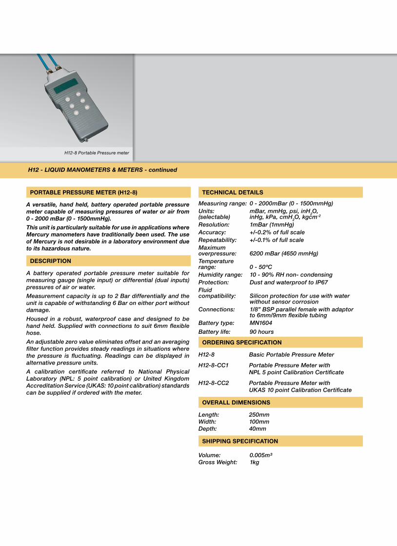
H12-8 Portable Pressure meter
PORTABLE PRESSURE METER (H12-8)
a versatile, hand held, battery operated portable pressure meter capable of measuring pressures of water or air from 0 - 2000 mBar (0 - 1500mmHg).
This unit is particularly suitable for use in applications where Mercury manometers have traditionally been used. The use of Mercury is not desirable in a laboratory environment due to its hazardous nature.
DESCRIPTION
A battery operated portable pressure meter suitable for measuring gauge (single input) or differential (dual inputs) pressures of air or water.
Measurement capacity is up to 2 Bar differentially and the unit is capable of withstanding 6 Bar on either port without damage.
Housed in a robust, waterproof case and designed to be hand held. Supplied with connections to suit 6mm flexible hose.
An adjustable zero value eliminates offset and an averaging filter function provides steady readings in situations where the pressure is fluctuating. Readings can be displayed in alternative pressure units.
A calibration certificate referred to National Physical Laboratory (NPL: 5 point calibration) or United Kingdom Accreditation Service (UKAS: 10 point calibration) standards can be supplied if ordered with the meter.
TECHNICAL DETAILS
Measuring range: 0 - 2000mBar (0 - 1500mmHg)Units: mBar, mmHg, psi, inH2O, (selectable) inHg, kPa, cmH2O, kgcm-2
Resolution: 1mBar (1mmHg)Accuracy: +/-0.2% of full scaleRepeatability: +/-0.1% of full scaleMaximum overpressure: 6200 mBar (4650 mmHg)Temperature range: 0 - 50ºCHumidity range: 10 - 90% RH non- condensingProtection: Dust and waterproof to IP67Fluid compatibility: Silicon protection for use with water
without sensor corrosionConnections: 1/8” BSP parallel female with adaptor
to 6mm/9mm flexible tubingBattery type: MN1604
Battery life: 90 hours
ORDERING SPECIFICATION
H12-8 Basic Portable Pressure Meter
H12-8-CC1 Portable Pressure Meter with NPL 5 point Calibration Certificate
H12-8-CC2 Portable Pressure Meter with UKAS 10 point Calibration Certificate
OVERALL DIMENSIONS
Length: 250mm Width: 100mm Depth: 40mm
SHIPPING SPECIFICATION
Volume: 0.005m³ Gross Weight: 1kg
H12 - LiQuiD ManoMeTeRs & MeTeRs - continued
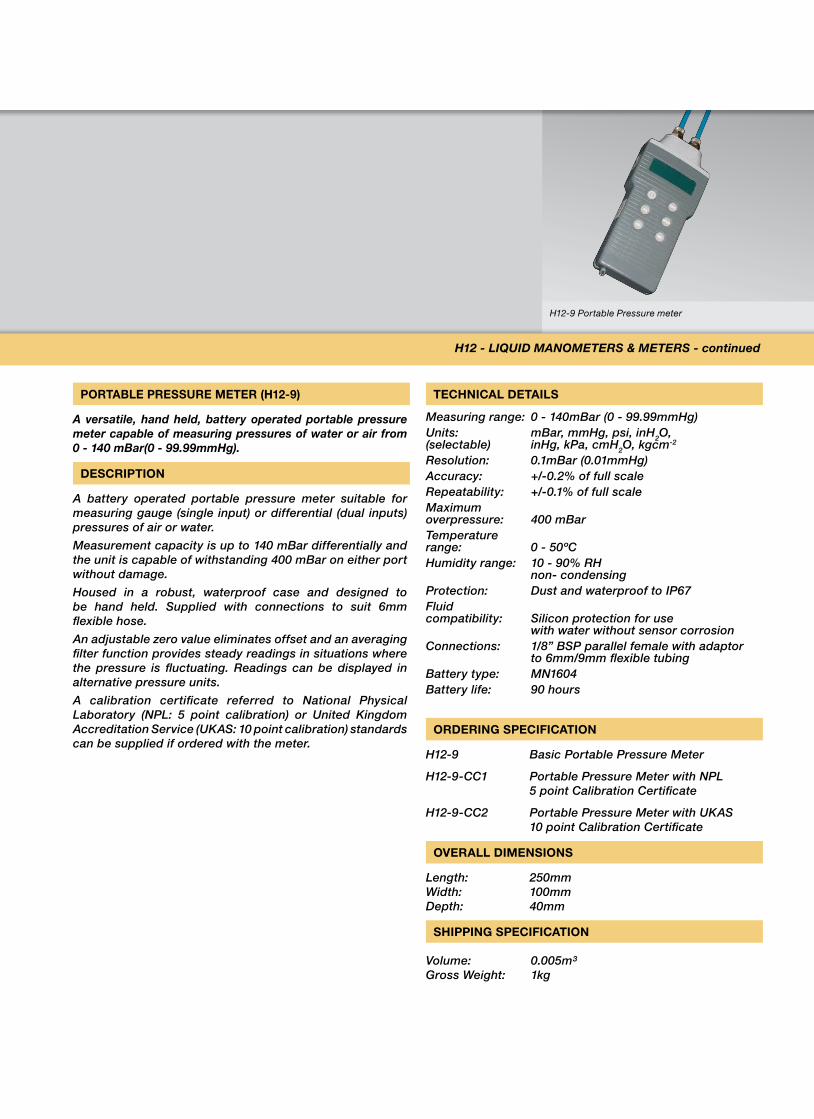
H12-9 Portable Pressure meter
PORTABLE PRESSURE METER (H12-9)
a versatile, hand held, battery operated portable pressure meter capable of measuring pressures of water or air from 0 - 140 mBar(0 - 99.99mmHg).
DESCRIPTION
A battery operated portable pressure meter suitable for measuring gauge (single input) or differential (dual inputs) pressures of air or water.
Measurement capacity is up to 140 mBar differentially and the unit is capable of withstanding 400 mBar on either port without damage.
Housed in a robust, waterproof case and designed to be hand held. Supplied with connections to suit 6mm flexible hose.
An adjustable zero value eliminates offset and an averaging filter function provides steady readings in situations where the pressure is fluctuating. Readings can be displayed in alternative pressure units.
A calibration certificate referred to National Physical Laboratory (NPL: 5 point calibration) or United Kingdom Accreditation Service (UKAS: 10 point calibration) standards can be supplied if ordered with the meter.
TECHNICAL DETAILS
Measuring range: 0 - 140mBar (0 - 99.99mmHg)Units: mBar, mmHg, psi, inH2O, (selectable) inHg, kPa, cmH2O, kgcm-2
Resolution: 0.1mBar (0.01mmHg)Accuracy: +/-0.2% of full scaleRepeatability: +/-0.1% of full scaleMaximum overpressure: 400 mBarTemperature range: 0 - 50ºCHumidity range: 10 - 90% RH non- condensingProtection: Dust and waterproof to IP67Fluid compatibility: Silicon protection for use with water without sensor corrosionConnections: 1/8” BSP parallel female with adaptor to 6mm/9mm flexible tubingBattery type: MN1604Battery life: 90 hours
ORDERING SPECIFICATION
H12-9 Basic Portable Pressure Meter
H12-9-CC1 Portable Pressure Meter with NPL 5 point Calibration Certificate
H12-9-CC2 Portable Pressure Meter with UKAS 10 point Calibration Certificate
OVERALL DIMENSIONS
Length: 250mm Width: 100mm Depth: 40mm
SHIPPING SPECIFICATION
Volume: 0.005m³ Gross Weight: 1kg
H12 - LiQuiD ManoMeTeRs & MeTeRs - continued
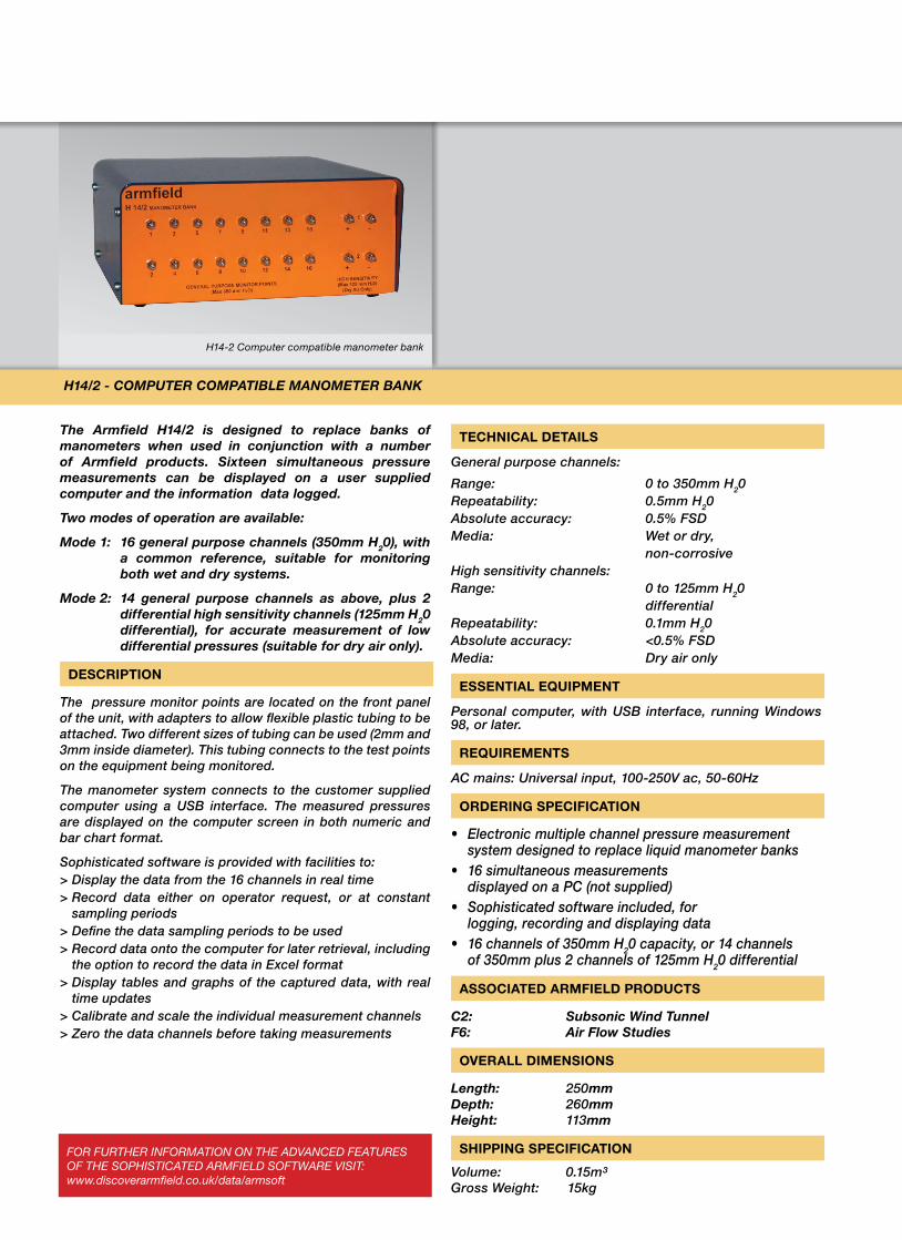
H14-2 Computer compatible manometer bank
For FurTHer inFormaTion on THe aDVanCeD FeaTures oF THe soPHisTiCaTeD armFieLD soFTware VisiT: www.discoverarmfield.co.uk/data/armsoft
The armfield H14/2 is designed to replace banks of manometers when used in conjunction with a number of armfield products. sixteen simultaneous pressure measurements can be displayed on a user supplied computer and the information data logged.
Two modes of operation are available:
Mode 1: 16 general purpose channels (350mm H20), with a common reference, suitable for monitoring both wet and dry systems.
Mode 2: 14 general purpose channels as above, plus 2 differential high sensitivity channels (125mm H20 differential), for accurate measurement of low differential pressures (suitable for dry air only).
DESCRIPTION
The pressure monitor points are located on the front panel of the unit, with adapters to allow flexible plastic tubing to be attached. Two different sizes of tubing can be used (2mm and 3mm inside diameter). This tubing connects to the test points on the equipment being monitored.
The manometer system connects to the customer supplied computer using a USB interface. The measured pressures are displayed on the computer screen in both numeric and bar chart format.
Sophisticated software is provided with facilities to:> Display the data from the 16 channels in real time> Record data either on operator request, or at constant
sampling periods> Define the data sampling periods to be used> Record data onto the computer for later retrieval, including
the option to record the data in Excel format> Display tables and graphs of the captured data, with real
time updates> Calibrate and scale the individual measurement channels> Zero the data channels before taking measurements
TECHNICAL DETAILS
General purpose channels:
Range: 0 to 350mm H20Repeatability: 0.5mm H20Absolute accuracy: 0.5% FSDMedia: Wet or dry, non-corrosiveHigh sensitivity channels:Range: 0 to 125mm H20 differentialRepeatability: 0.1mm H20Absolute accuracy: <0.5% FSDMedia: Dry air only
ESSENTIAL EQUIPMENT
Personal computer, with USB interface, running Windows 98, or later.
REQUIREMENTS
AC mains: Universal input, 100-250V ac, 50-60Hz
ORDERING SPECIFICATION
• Electronicmultiplechannelpressuremeasurementsystem designed to replace liquid manometer banks
• 16simultaneousmeasurementsdisplayed on a PC (not supplied)
• Sophisticatedsoftwareincluded,forlogging, recording and displaying data
• 16channelsof350mmH20 capacity, or 14 channels of 350mm plus 2 channels of 125mm H20 differential
ASSOCIATED ARMFIELD PRODUCTS
c2: subsonic Wind Tunnel F6: air Flow studies
OVERALL DIMENSIONS
Length: 250mm Depth: 260mm Height: 113mm
SHIPPING SPECIFICATION
Volume: 0.15m³Gross Weight: 15kg
H14/2 - coMPuTeR coMPaTiBLe ManoMeTeR Bank
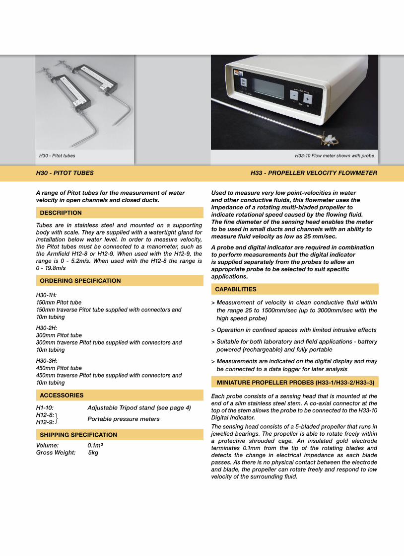
H30 - Pitot tubes H33-10 Flow meter shown with probe
a range of Pitot tubes for the measurement of water velocity in open channels and closed ducts.
DESCRIPTION
Tubes are in stainless steel and mounted on a supporting body with scale. They are supplied with a watertight gland for installation below water level. In order to measure velocity, the Pitot tubes must be connected to a manometer, such as the Armfield H12-8 or H12-9. When used with the H12-9, the range is 0 - 5.2m/s. When used with the H12-8 the range is 0 - 19.8m/s
ORDERING SPECIFICATION
H30-1H: 150mm Pitot tube 150mm traverse Pitot tube supplied with connectors and 10m tubing
H30-2H: 300mm Pitot tube 300mm traverse Pitot tube supplied with connectors and 10m tubing
H30-3H: 450mm Pitot tube 450mm traverse Pitot tube supplied with connectors and 10m tubing
ACCESSORIES
H1-10: Adjustable Tripod stand (see page 4) H12-8:}
Portable pressure meters H12-9:
SHIPPING SPECIFICATION
Volume: 0.1m³Gross Weight: 5kg
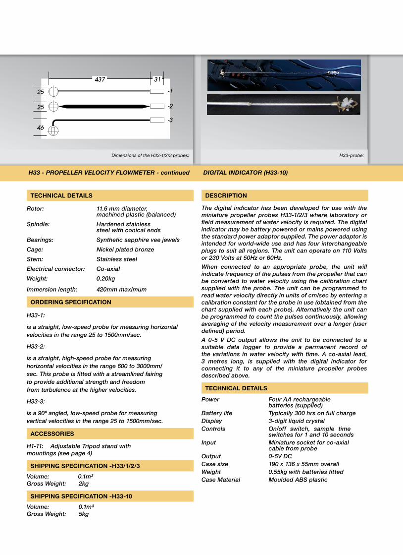
used to measure very low point-velocities in water and other conductive fluids, this flowmeter uses the impedance of a rotating multi-bladed propeller to indicate rotational speed caused by the flowing fluid. The fine diameter of the sensing head enables the meter to be used in small ducts and channels with an ability to measure fluid velocity as low as 25 mm/sec.
a probe and digital indicator are required in combination to perform measurements but the digital indicator is supplied separately from the probes to allow an appropriate probe to be selected to suit specific applications.
CAPABILITIES
> Measurement of velocity in clean conductive fluid within the range 25 to 1500mm/sec (up to 3000mm/sec with the high speed probe)
> Operation in confined spaces with limited intrusive effects
> Suitable for both laboratory and field applications - battery powered (rechargeable) and fully portable
> Measurements are indicated on the digital display and may be connected to a data logger for later analysis
MINIATURE PROPELLER PROBES (H33-1/H33-2/H33-3)
Each probe consists of a sensing head that is mounted at the end of a slim stainless steel stem. A co-axial connector at the top of the stem allows the probe to be connected to the H33-10 Digital Indicator.
The sensing head consists of a 5-bladed propeller that runs in jewelled bearings. The propeller is able to rotate freely within a protective shrouded cage. An insulated gold electrode terminates 0.1mm from the tip of the rotating blades and detects the change in electrical impedance as each blade passes. As there is no physical contact between the electrode and blade, the propeller can rotate freely and respond to low velocity of the surrounding fluid.
H30 - PiToT TuBes H33 - PRoPeLLeR VeLociTY FLoWMeTeR
Dimensions of the H33-1/2/3 probes: H33-probe:
TECHNICAL DETAILS
Rotor: 11.6 mm diameter, machined plastic (balanced)
Spindle: Hardened stainless steel with conical ends
Bearings: Synthetic sapphire vee jewels
Cage: Nickel plated bronze
Stem: Stainless steel
Electrical connector: Co-axial
Weight: 0.20kg
Immersion length: 420mm maximum
ORDERING SPECIFICATION
H33-1:
is a straight, low-speed probe for measuring horizontal velocities in the range 25 to 1500mm/sec.
H33-2:
is a straight, high-speed probe for measuring horizontal velocities in the range 600 to 3000mm/sec. This probe is fitted with a streamlined fairing to provide additional strength and freedom from turbulence at the higher velocities.
H33-3:
is a 90º angled, low-speed probe for measuring vertical velocities in the range 25 to 1500mm/sec.
ACCESSORIES
H1-11: Adjustable Tripod stand with mountings (see page 4)
SHIPPING SPECIFICATION -H33/1/2/3
Volume: 0.1m³Gross Weight: 2kg
SHIPPING SPECIFICATION -H33-10
Volume: 0.1m³ Gross Weight: 5kg
DESCRIPTION
The digital indicator has been developed for use with the miniature propeller probes H33-1/2/3 where laboratory or field measurement of water velocity is required. The digital indicator may be battery powered or mains powered using the standard power adaptor supplied. The power adaptor is intended for world-wide use and has four interchangeable plugs to suit all regions. The unit can operate on 110 Volts or 230 Volts at 50Hz or 60Hz.
When connected to an appropriate probe, the unit will indicate frequency of the pulses from the propeller that can be converted to water velocity using the calibration chart supplied with the probe. The unit can be programmed to read water velocity directly in units of cm/sec by entering a calibration constant for the probe in use (obtained from the chart supplied with each probe). Alternatively the unit can be programmed to count the pulses continuously, allowing averaging of the velocity measurement over a longer (user defined) period.
A 0-5 V DC output allows the unit to be connected to a suitable data logger to provide a permanent record of the variations in water velocity with time. A co-axial lead, 3 metres long, is supplied with the digital indicator for connecting it to any of the miniature propeller probes described above.
TECHNICAL DETAILS
Power Four AA rechargeable batteries (supplied)
Battery life Typically 300 hrs on full chargeDisplay 3-digit liquid crystalControls On/off switch, sample time
switches for 1 and 10 secondsInput Miniature socket for co-axial
cable from probeOutput 0-5V DCCase size 190 x 136 x 55mm overallWeight 0.55kg with batteries fittedCase Material Moulded ABS plastic
H33 - PRoPeLLeR VeLociTY FLoWMeTeR - continued DiGiTaL inDicaToR (H33-10)
25
25
46
-1
-2
-3
437 31
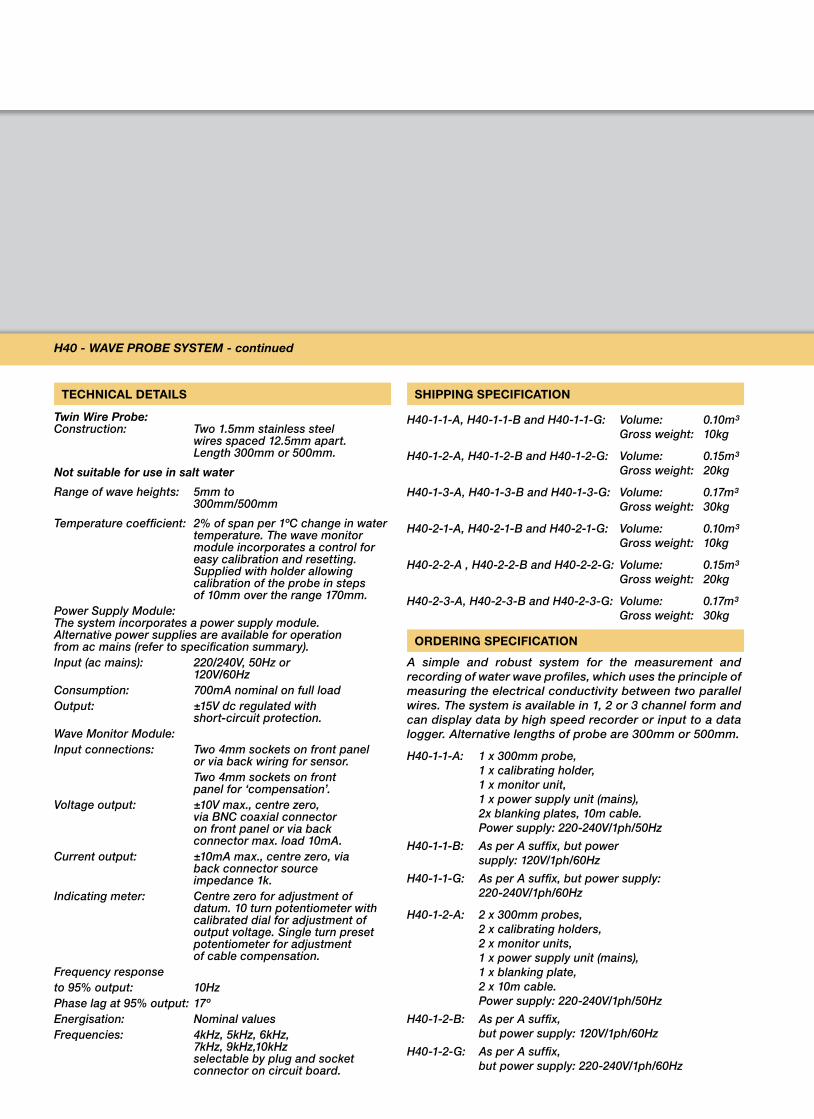
H40 monitor module & probe
H40 - WaVe PRoBe sYsTeM
a simple and robust instrument for the measurement and recording of water waves in hydraulic models and ship tanks, which works on the principle of measuring the electrical conductivity between two parallel wires.
INSTRUCTIONAL CAPABILITIES
> easily set up and calibrated
> high dynamic accuracy
> linear calibration over a large range
> outputs for high speed recorders and data loggers
> can be operated at different energisation frequencies to avoid mutual interaction between two or more closely spaced probes
> supplied as a complete working system, with the option of 1, 2, or 3 channels of measurement
DESCRIPTION
Each probe consists of a pair of stainless steel wires which dip into the water waves. The electrical conductivity between them is measured, and is linearly related to their depth of immersion hence to wave height. The method is free of meniscus and `wetting´ effects.
The result is a system giving high dynamic accuracy over a wide range of wave heights and frequencies.
Energisation is conducted by means of an audio frequency drive signal which avoids all polarisation effects at the wire interface. The signal is balanced relative to earth, to render the system immune to common mode voltages between the water and instrument earth. The frequency can be altered to permit two or more sensors to operate in close proximity without mutual interference.
The probe consists of two 1.5mm diameter stainless steel wires spaced 12.5mm apart and 300mm long or 500mm long as required.
Each probe is connected to its own wave monitor module in the electronic console by a twin core flexible cable 10m long. The distance between the console and probe may be increased up to 100m using commonly available low current cables.
The power supply module and appropriate number of wave monitor modules are mounted in a console, finished in matt textured blue paint and fitted with four rubber feet and carrying handle.
High quality GRP circuit boards are rigidly mounted in heavy duty plug-in modules. Rear connections are via heavy duty plug and socket connectors.
Each module is supplied with a calibrated holder which permits easy setting and checking of overall system calibration, from the probe to a recorder or data logger (to be supplied by the user) by allowing the sensor to be moved vertically in steps of 10mm up to a maximum of 170mm.
The wave monitor module provides output signals to drive a chart recorder or for input to a data logger (both to be supplied by the user). The records enable wave height, frequency and profile to be observed. Wave velocity can be measured by means of two sensors, spaced a known distance apart, each giving a recorder trace via its own monitor module.
The module incorporates a unique system of compensation for the resistance of the probe connecting cable which ensures that the characteristic of the probe remains linear, even for large dynamic ranges.
The compensation is set up quickly and easily by disconnecting the cable at the probe end and plugging it into two additional sockets on the module panel, and then adjusting a preset potentiometer.
No additional modules or test instruments are required.
A ‘Datum’ control enables the output from the module to be set to zero for any chosen depth of probe immersion.
A power supply incorporated in the electronic console provides ±15V regulated outputs.
H40 - WaVe PRoBe sYsTeM - continued
TECHNICAL DETAILS
Twin Wire Probe: Construction: Two 1.5mm stainless steel
wires spaced 12.5mm apart.Length 300mm or 500mm.
not suitable for use in salt water
Range of wave heights: 5mm to 300mm/500mm
Temperature coefficient: 2% of span per 1ºC change in water temperature. The wave monitor module incorporates a control for easy calibration and resetting. Supplied with holder allowing calibration of the probe in steps of 10mm over the range 170mm.
Power Supply Module: The system incorporates a power supply module. Alternative power supplies are available for operation from ac mains (refer to specification summary).Input (ac mains): 220/240V, 50Hz or 120V/60HzConsumption: 700mA nominal on full loadOutput: ±15V dc regulated with short-circuit protection.Wave Monitor Module:Input connections: Two 4mm sockets on front panel
or via back wiring for sensor. Two 4mm sockets on front
panel for ‘compensation’.Voltage output: ±10V max., centre zero,
via BNC coaxial connector on front panel or via back connector max. load 10mA.
Current output: ±10mA max., centre zero, via back connector source impedance 1k.
Indicating meter: Centre zero for adjustment of datum. 10 turn potentiometer with calibrated dial for adjustment of output voltage. Single turn preset potentiometer for adjustment of cable compensation.
Frequency responseto 95% output: 10HzPhase lag at 95% output: 17ºEnergisation: Nominal values Frequencies: 4kHz, 5kHz, 6kHz,
7kHz, 9kHz,10kHz selectable by plug and socket connector on circuit board.
SHIPPING SPECIFICATION
H40-1-1-A, H40-1-1-B and H40-1-1-G: Volume: 0.10m³ Gross weight: 10kg
H40-1-2-A, H40-1-2-B and H40-1-2-G: Volume: 0.15m³ Gross weight: 20kg
H40-1-3-A, H40-1-3-B and H40-1-3-G: Volume: 0.17m³ Gross weight: 30kg
H40-2-1-A, H40-2-1-B and H40-2-1-G: Volume: 0.10m³ Gross weight: 10kg
H40-2-2-A , H40-2-2-B and H40-2-2-G: Volume: 0.15m³ Gross weight: 20kg
H40-2-3-A, H40-2-3-B and H40-2-3-G: Volume: 0.17m³ Gross weight: 30kg
ORDERING SPECIFICATION
A simple and robust system for the measurement and recording of water wave profiles, which uses the principle of measuring the electrical conductivity between two parallel wires. The system is available in 1, 2 or 3 channel form and can display data by high speed recorder or input to a data logger. Alternative lengths of probe are 300mm or 500mm.
H40-1-1-A: 1 x 300mm probe, 1 x calibrating holder, 1 x monitor unit, 1 x power supply unit (mains), 2x blanking plates, 10m cable. Power supply: 220-240V/1ph/50Hz
H40-1-1-B: As per A suffix, but power supply: 120V/1ph/60Hz
H40-1-1-G: As per A suffix, but power supply: 220-240V/1ph/60Hz
H40-1-2-A: 2 x 300mm probes, 2 x calibrating holders, 2 x monitor units, 1 x power supply unit (mains), 1 x blanking plate, 2 x 10m cable. Power supply: 220-240V/1ph/50Hz
H40-1-2-B: As per A suffix, but power supply: 120V/1ph/60Hz
H40-1-2-G: As per A suffix, but power supply: 220-240V/1ph/60Hz
H40 ORDERING SPECIFICATION - continued
H40-1-3-A: 3 x 300mm probes, 3 x calibrating holders, 3 x monitor units, 1 x power supply unit (mains), 3 x 10m cable. Power supply: 220-240V/1ph/50Hz
H40-1-3-B: As per A suffix, but power supply: 120V/1ph/60Hz
H40-1-3-G: As per A suffix, but power supply: 220-240V/1ph/60Hz
H40-2-1-A: 1 x 500mm probe, 1 x calibrating holder, 1 x monitor unit, 1 x power supply unit (mains), 2 x blanking plates, 10m cable. Power supply: 220-240V/1ph/50Hz
H40-2-1-B: As per A suffix, but power supply: 120V/1ph/60Hz
H40-2-1-G: As per A suffix, but power supply: 220-240V/1ph/60Hz
H40-2-2-A: 2 x 500mm probe, 2 x calibrating holder, 2 x monitor units, 1 x power supply unit (mains), 1 x blanking plate, 2 x 10m cable. Power supply: 220-240V/1ph/50Hz
H40-2-2-B: As per A suffix, but power supply: 120V/1ph/60Hz
H40-2-2-G: As per A suffix, but power supply: 220-240V/1ph/60Hz
H40-2-3-A: 3 x 500mm probe, 3 x calibrating holder, 3 x monitor units, 1 x power supply unit (mains), 3 x 10m cable. Power supply: 220-240V/1ph/50Hz
H40-2-3-B: As per A suffix, but power supply: 120V/1ph/60Hz
H40-2-3-G: As per A suffix, but power supply: 220-240V/1ph/60Hz
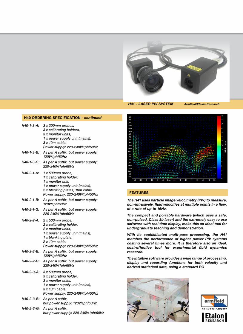
H41 - LaseR PiV sYsTeM armfield/etalon Research
An ISO 9001 Company
FEATURES
The H41 uses particle image velocimetry (PiV) to measure, non-intrusively, fluid velocities at multiple points in a flow, at a rate of up to 16Hz.
The compact and portable hardware (which uses a safe, non-pulsed, class 3b laser) and the extremely easy to use software with real time display, make this an ideal tool for undergraduate teaching and demonstration.
With its sophisticated multi-pass processing, the H41 matches the performance of higher power PiV systems costing several times more. it is therefore also an ideal, cost-effective tool for experimental fluid dynamics research.
The intuitive software provides a wide range of processing, display and recording functions for both velocity and derived statistical data, using a standard Pc
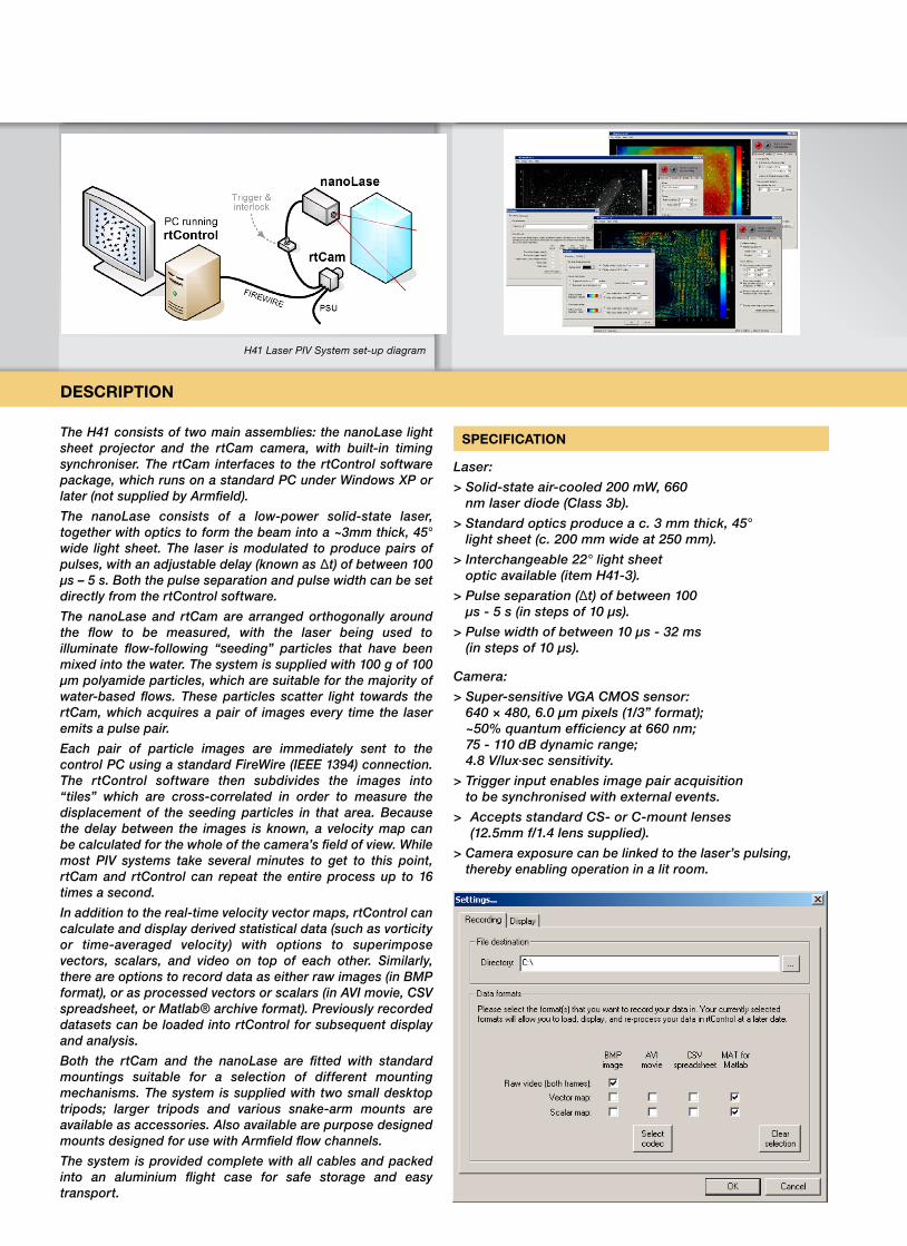
Typical software screenshotsH41 Laser PiV system set-up diagram
The H41 consists of two main assemblies: the nanoLase light sheet projector and the rtCam camera, with built-in timing synchroniser. The rtCam interfaces to the rtControl software package, which runs on a standard PC under Windows XP or later (not supplied by Armfield).
The nanoLase consists of a low-power solid-state laser, together with optics to form the beam into a ~3mm thick, 45° wide light sheet. The laser is modulated to produce pairs of pulses, with an adjustable delay (known as Δt) of between 100 μs – 5 s. Both the pulse separation and pulse width can be set directly from the rtControl software.
The nanoLase and rtCam are arranged orthogonally around the flow to be measured, with the laser being used to illuminate flow-following “seeding” particles that have been mixed into the water. The system is supplied with 100 g of 100 μm polyamide particles, which are suitable for the majority of water-based flows. These particles scatter light towards the rtCam, which acquires a pair of images every time the laser emits a pulse pair.
Each pair of particle images are immediately sent to the control PC using a standard FireWire (IEEE 1394) connection. The rtControl software then subdivides the images into “tiles” which are cross-correlated in order to measure the displacement of the seeding particles in that area. Because the delay between the images is known, a velocity map can be calculated for the whole of the camera’s field of view. While most PIV systems take several minutes to get to this point, rtCam and rtControl can repeat the entire process up to 16 times a second.
In addition to the real-time velocity vector maps, rtControl can calculate and display derived statistical data (such as vorticity or time-averaged velocity) with options to superimpose vectors, scalars, and video on top of each other. Similarly, there are options to record data as either raw images (in BMP format), or as processed vectors or scalars (in AVI movie, CSV spreadsheet, or Matlab® archive format). Previously recorded datasets can be loaded into rtControl for subsequent display and analysis.
Both the rtCam and the nanoLase are fitted with standard mountings suitable for a selection of different mounting mechanisms. The system is supplied with two small desktop tripods; larger tripods and various snake-arm mounts are available as accessories. Also available are purpose designed mounts designed for use with Armfield flow channels.
The system is provided complete with all cables and packed into an aluminium flight case for safe storage and easy transport.
SPECIFICATION
Laser:
> Solid-state air-cooled 200 mW, 660 nm laser diode (Class 3b).
> Standard optics produce a c. 3 mm thick, 45° light sheet (c. 200 mm wide at 250 mm).
> Interchangeable 22° light sheet optic available (item H41-3).
> Pulse separation (Δt) of between 100 μs - 5 s (in steps of 10 μs).
> Pulse width of between 10 μs - 32 ms (in steps of 10 μs).
Camera:
> Super-sensitive VGA CMOS sensor: 640 × 480, 6.0 μm pixels (1/3” format); ~50% quantum efficiency at 660 nm; 75 - 110 dB dynamic range; 4.8 V/lux·sec sensitivity.
> Trigger input enables image pair acquisition to be synchronised with external events.
> Accepts standard CS- or C-mount lenses (12.5mm f/1.4 lens supplied).
> Camera exposure can be linked to the laser’s pulsing, thereby enabling operation in a lit room.
DESCRIPTION
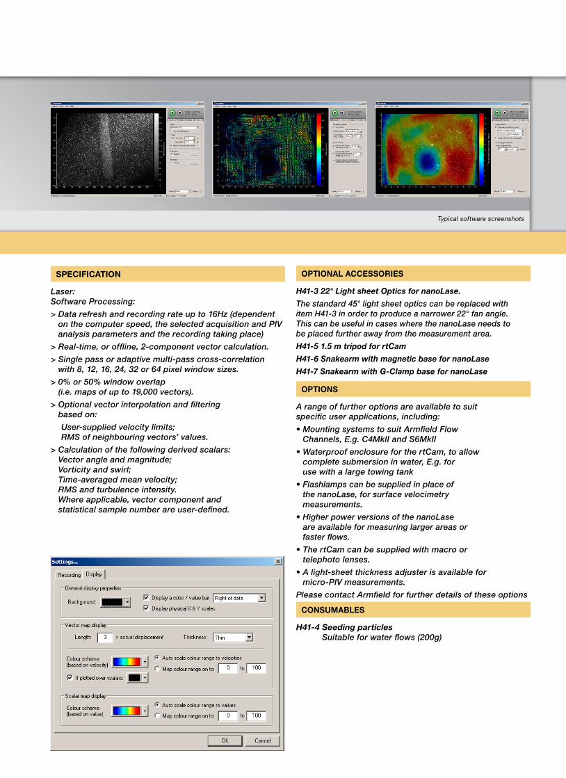
Typical software screenshots
SPECIFICATION
Laser: Software Processing:
> Data refresh and recording rate up to 16Hz (dependent on the computer speed, the selected acquisition and PIV analysis parameters and the recording taking place)
> Real-time, or offline, 2-component vector calculation.
> Single pass or adaptive multi-pass cross-correlation with 8, 12, 16, 24, 32 or 64 pixel window sizes.
> 0% or 50% window overlap (i.e. maps of up to 19,000 vectors).
> Optional vector interpolation and filtering based on:
User-supplied velocity limits; RMS of neighbouring vectors’ values.
> Calculation of the following derived scalars: Vector angle and magnitude; Vorticity and swirl; Time-averaged mean velocity; RMS and turbulence intensity. Where applicable, vector component and statistical sample number are user-defined.
OPTIONAL ACCESSORIES
H41-3 22° Light sheet optics for nanoLase.
The standard 45° light sheet optics can be replaced with item H41-3 in order to produce a narrower 22° fan angle. This can be useful in cases where the nanoLase needs to be placed further away from the measurement area.
H41-5 1.5 m tripod for rtcam
H41-6 snakearm with magnetic base for nanoLase
H41-7 snakearm with G-clamp base for nanoLase
OPTIONS
A range of further options are available to suit specific user applications, including:
•MountingsystemstosuitArmfieldFlowChannels, E.g. C4MkII and S6MkII
•WaterproofenclosureforthertCam,toallow complete submersion in water, E.g. for use with a large towing tank
•Flashlamps can be supplied in place of the nanoLase, for surface velocimetry measurements.
•Higher power versions of the nanoLase are available for measuring larger areas or faster flows.
•ThertCamcanbesuppliedwithmacroor telephoto lenses.
•Alight-sheetthicknessadjusterisavailablefor micro-PIV measurements.
Please contact Armfield for further details of these options
CONSUMABLES
H41-4 seeding particles Suitable for water flows (200g)
©2009 Armfield Ltd. All Rights Reserved We reserve the right to amend these specifications without prior notice. E&OE 1109/3k/SO2796
Head Office: Armfield Limited Bridge House, West Street, ringwood, Hampshire. BH24 1DY england
Telephone: +44 1425 478781Fax: +44 1425 470916e-mail: [email protected]
U.S. Office: Armfield inc. 436 West Commodore Blvd (#2) Jackson, NJ 08527Telephone: (732) 928 3332Fax: (732) 928 3542e-mail: [email protected]
2 -YR WARRANTY ON ALL ARMFIEL
D PRO
DUCT
S
<EXTENDED> WARRANTY
2 years
if you dispose of this data sheet please recycle it.
Sourced from fully sustainable forests ISO 14001/TCF Certified
An ISO 9001 Company
Innovators in Engineering Teaching Equipment
learn more! www.armfield.co.uk
Scan Qr code* to download the latest version of this datasheet or click: www.armfield.co.uk/h* Scan with mobile smartphone or webcam
with barcode scanning software installed.
NOTE: H1 and H40 are manufactured under licence to the designs of Hydraulics Research, Wallingford, England
For FurTHer inFormaTion on THe aDVanCeD FeaTures oF THe soPHisTiCaTeD armFieLD soFTware VisiT: www.discoverarmfield.co.uk/data/armsoft
ORDERING DETAILS
H41-1 Laser PIV System for Flow measurement and Visualisation
H41-2 Laser PIV System for Flow measurement and Visualisation with submersible nanoLase light sheet projector.
REQUIREMENTSelectrical supply: H41-1-A, H41-2-A 220-240V, 50Hz H41-1-B, H41-2-B 115V, 60Hz H41-1-G, H41-2-G 230V, 60Hz
Personal Computer (PC) running Windows XP or later, with IEEE 1394 (A or B) interface.
It is recommended that the PC has at least 2GB RAM with a processing speed of at least 2GHz. The display resolution should be at least 1024 × 768, true colour.
The data refresh rate achievable is dependent on the specification of this computer. For example, to achieve 16Hz data refresh and recording rate, a 2.66GHz Intel dual core processor or better is required, and the hard
drive must support sustained writes at 9.5 Mb/s.
OVERALL DIMENSIONS nanoLase Length: 0.050m Width: 0.050m Height: 0.085m
submersible nanoLase Length: 0.050m Width: 0.050m Height: 0.095m
rtcam Length: 0.050m Width: 0.050m Height: 0.090m
SHIPPING SPECIFICATIONVolume: 0.1m3 Gross weight: 6kg
ORDERING SPECIFICATION - H41-1• ParticleImageVelocimetrySystem,comprisinga
laser light sheet projector, a camera system and processing software
•200mW(Class3b)660nmlaser,withvariablepulsewidth and pulse spacing
•45° light sheet optics as standard with optionaloptics to produce a 22° sheet
•Real-time 2D display of flow velocity vectorsupdated at up to 16 Hz
•Datacanberecordedinvideo(avi),bitmap(bmp),text (csv) and Matlab (mat) formats
ORDERING SPECIFICATION - H41-2• ParticleImageVelocimetrySystem,comprisinga
laser light sheet projector, a camera system and processing software
•200mW(Class3b)660nmlaser,withvariablepulsewidth and pulse spacing
•45° light sheet optics as standard with optionaloptics to produce a 22° sheet
•Real-time 2D display of flow velocity vectorsupdated at up to 16 Hz
•Datacanberecordedinvideo(avi),bitmap(bmp),text (csv) and Matlab (mat) formats
•Submersiblelightsheetprojector
WITH DISCOVER