GY305 Lecture4 Seismology - southalabama.edu Strike-Slip Example of 1st Motion • Compressional 1st...
26
GY305 GEOPHYSICS Seismology
Transcript of GY305 Lecture4 Seismology - southalabama.edu Strike-Slip Example of 1st Motion • Compressional 1st...

GY305 GEOPHYSICSSeismology

Seismology & Seismic Waves
• Seismology is the study of the transmission of seismic wave energy through the Earth
• 3 fundamental seismic waves• P-wave: compressional wave• S-wave: shear wave• Surface wave: wave that travels along the surface of the earth
• Seismic wave transmission can me used to remotely measure physical properties of the internal layers of the Earth:
• Transmission speed is proportional to density• Density contrasts cause reflection and refraction according to
Snell’s law• S-waves cannot be transmitted through a liquid

Physics of Seismic Waves
• P-wave: particle motion vibrates in the direction of wave-front travel
• S-wave: particle motion vibrates perpendicular to the direction of wave travel
• Surface Wave: composed of Rayleigh and Love waves:• Rayleigh: particle motion perpendicular to ground
surface• Love: particle motion parallel to ground surface
• P-waves and S-waves are considered “Body” waves because they travel through the Earth’s interior
• P-waves have higher velocities and therefore arrive at seismograph stations 1st
• S-waves have an intermediate velocity and arrive 2nd
• Surface waves are slower than P- or S- waves and therefore arrive last

P- versus S-wave Particle Motion
P-wave S-wave

Rayleigh versus Love Components of Surface Waves
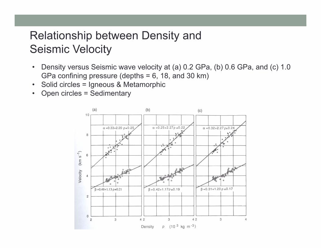
Relationship between Density and Seismic Velocity• Density versus Seismic wave velocity at (a) 0.2 GPa, (b) 0.6 GPa, and (c) 1.0
GPa confining pressure (depths = 6, 18, and 30 km)• Solid circles = Igneous & Metamorphic• Open circles = Sedimentary

Earthquake Seismology Terms
• Seismograph: instrument that records the arrival of seismic waves at the instrument location over time
• Seismic station network: global array of seismic stations built to detect the location and magnitude of seismic events, natural and man-made
• Epicenter: 2D location of seismic event on a map- requires latitude & longitude
• Focal Point: 3D location- latitude, longitude, and depth• Magnitude: measure of the release of energy from the
seismic event

Earthquake Epicentral Distance
• Because P-waves travel faster than S-waves the epicentral distance from the seismic station may be calculated
• The time differential (∆t) is proportional to the epicentral distance
1:00:00PM 1:00:10PM 1:00:20PM 1:00:30PM 1:00:40PM
P-wave S-wave
TP=1:00:05PM TS=1:00:12PM
∆t=1:00:12-1:00:05=7 secondsSeismic Station A
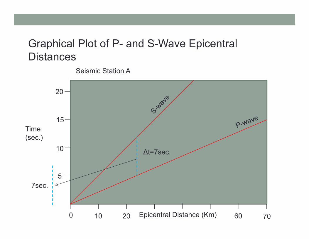
Graphical Plot of P- and S-Wave Epicentral Distances
Epicentral Distance (Km)
Time (sec.)
0 10 6020 70
5
10
15
20
∆t=7sec.
7sec.
Seismic Station A

Plotting Epicenter Location
Seismic Station
Epicentral Distance
A 23 kmB 57 kmC 30 km
A
B
C

Calculation of the Time of the Seismic Event
Epicentral Distance (Km)
Time (sec.)
0 10 6020 70
5
10
15
20
∆t=7sec.
• Once the epicentral distance is calculated the time of arrival of the P- or S-wave at any of the seismic stations can be used to calculate the time of the seismic event
P-wave travel time = 5 sec.
Seismic Event time = 1:00:05PM – 5 sec. = 1:00:00PM

Earthquake Magnitude
• All earthquake magnitude calculations (i,.e. Richter scale) are derived from the below equation:
• M = Log(A/T) + q(,h) + a• A = Amplitude of wave in 10-6 meters• T = period of wave in seconds• q = function correcting for () angular distance from
seismometer to epicenter, and for (h) the focal depth• a = an empirical constant that takes into account variations
specific to the seismic station and seismic instrument• Note the log scale – a magnitude 8 event releases
thousands of times the energy compared to a magnitude 5 event

Earthquake Magnitude Frequency
Magnitude Number per Year> 8.0 17 – 7.9 186 – 6.9 1085 - 5.9 8004-4.9 6,2003 – 3.9 49,0002-2.9 300,000
*Mean annual frequency of earthquakes recorded 1918-1945(Gutenberg and Richter, 1954)

Seismic Wave Paths in the Earth
• P- and S-waves travel in curved paths because of refraction
• Rapid density changes across contacts may also cause reflections
• S-waves will not transmit through the liquid outer core
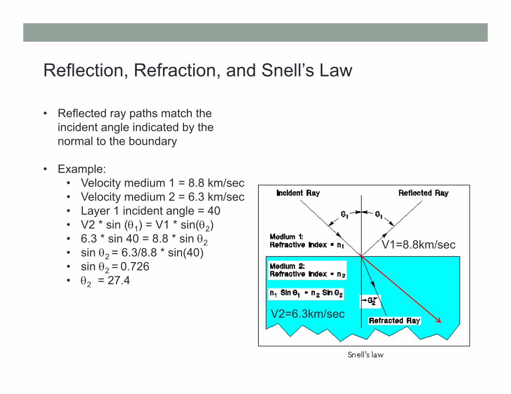
Reflection, Refraction, and Snell’s Law
• Reflected ray paths match the incident angle indicated by the normal to the boundary
• Example:• Velocity medium 1 = 8.8 km/sec• Velocity medium 2 = 6.3 km/sec• Layer 1 incident angle = 40• V2 * sin (1) = V1 * sin(2)• 6.3 * sin 40 = 8.8 * sin 2• sin 2 = 6.3/8.8 * sin(40)• sin 2 = 0.726• 2 = 27.4
V1=8.8km/sec
V2=6.3km/sec

1st Motion Studies and Fault Motion Solutions
• P-wave 1st arrivals at seismic stations will be either compressional or dilational
• This will indicate the relative fault block motion along a fracture and therefore the type of fault (normal, reverse, dextral, sinistral)
Sinistral strike-slip
Normal Dip-slip Reverse Dip-Slip

Dextral Strike-Slip Example of 1st Motion• Compressional 1st motion displays as a positive “up-tick” on strip chart• Dilational 1st motion displays as a negative “down-tick” on strip chart• Note that 1st motion gives 2 possible fault plane solutions- you need some
knowledge of the regional geology to determine the correct fault plane• Note that the intensity of the P-wave amplitude decreases to 0 at the nodal
plane

Example of Dextral Strike-Slip Motion on an East-West Transform
• Solid circles are compressional 1st Motions
• Open circles are dilational 1st
motions• Circles with crosses are low-
amplitude indeterminate

Example 1st Motion Data From Dip-Slip Faults
Normal Reverse
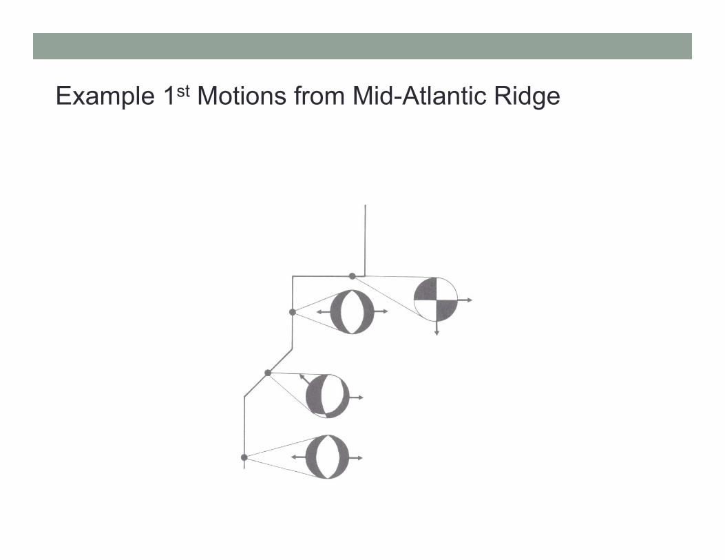
Example 1st Motions from Mid-Atlantic Ridge

Relationship of Seismic Wave Velocity to Earth’s Internal Layers
• Phase changes create rapid density changes
• Physical state (solid vs. liquid) generate velocity gradients
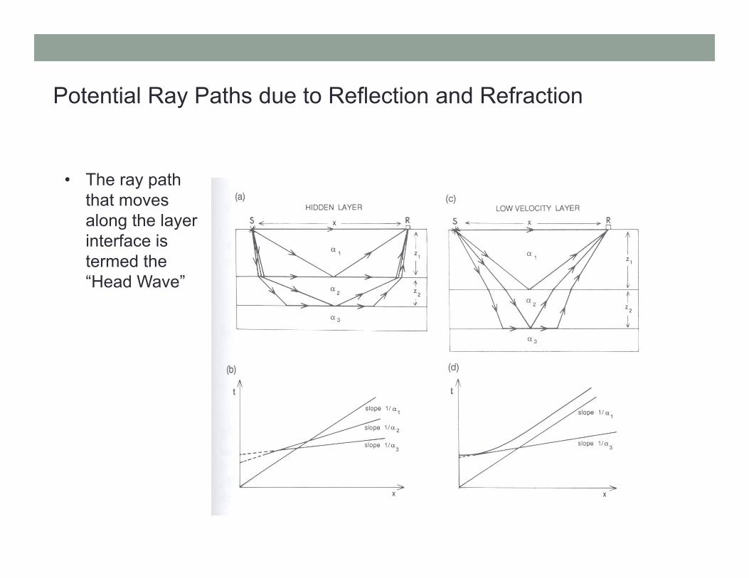
Potential Ray Paths due to Reflection and Refraction
• The ray path that moves along the layer interface is termed the “Head Wave”
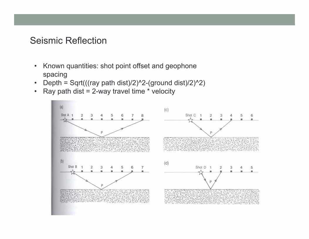
Seismic Reflection
• Known quantities: shot point offset and geophone spacing
• Depth = Sqrt(((ray path dist)/2)^2-(ground dist)/2)^2)• Ray path dist = 2-way travel time * velocity

Seismic Reflection cont.
• 2-way travel times on a horizontal surface follow a hyperbolic trend

Seismic Reflection: Fault Offset
• Fault offset produces an offset in hyperbolic curve

Consolidated Reflection Data
• Multiple Shot points are collected by computers and processed into a reflection profile
• Below is a profile through the Rio Grande Rift displaying the top of the rift magma chamber