Gunnebo Lifting - GrabiQ - · PDF fileGrabiQ™ by Gunnebo Lifting ... Intelligent design...
24
The All-Inclusive Chain Sling System for Coupling and Shortening GrabiQ ™ by Gunnebo Lifting 2013
Transcript of Gunnebo Lifting - GrabiQ - · PDF fileGrabiQ™ by Gunnebo Lifting ... Intelligent design...
The All-Inclusive Chain Sling System for Coupling and Shortening
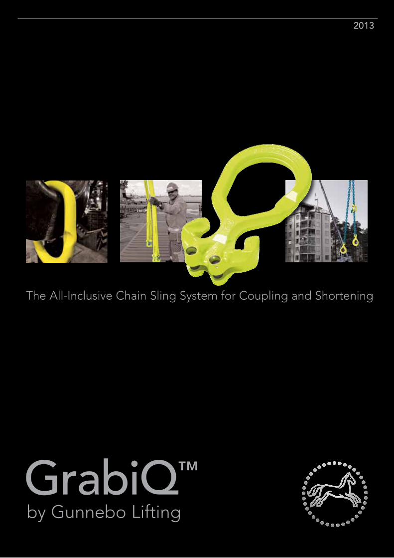
GrabiQ™
by Gunnebo Lifting
2013
2
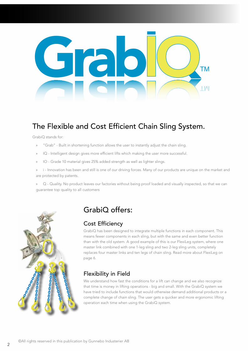
The Flexible and Cost Efficient Chain Sling System. GrabiQ stands for:
» ”Grab” - Built in shortening function allows the user to instantly adjust the chain sling.
» IQ - Intelligent design gives more efficient lifts which making the user more successful.
» IO - Grade 10 material gives 25% added strength as well as lighter slings.
» i - Innovation has been and still is one of our driving forces. Many of our products are unique on the market and
are protected by patents.
» Q - Quality. No product leaves our factories without being proof loaded and visually inspected, so that we can
guarantee top quality to all customers
Cost EfficiencyGrabiQ has been designed to integrate multiple functions in each component. This means fewer components in each sling, but with the same and even better function than with the old system. A good example of this is our FlexiLeg system, where one master link combined with one 1-leg sling and two 2-leg sling units, completely replaces four master links and ten legs of chain sling. Read more about FlexiLeg on page 6.
Flexibility in FieldWe understand how fast the conditions for a lift can change and we also recognize that time is money in lifting operations - big and small. With the GrabiQ system we have tried to include functions that would otherwise demand additional products or a complete change of chain sling. The user gets a quicker and more ergonomic lifting operation each time when using the GrabiQ system.
©All rights reserved in this publication by Gunnebo Industerier AB
GrabiQ offers:
4
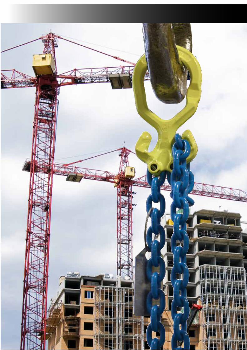
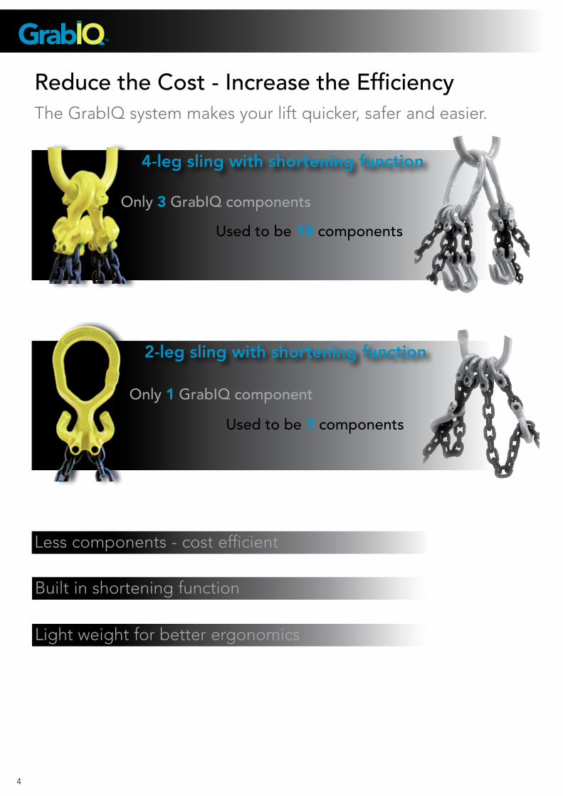
Reduce the Cost - Increase the EfficiencyThe GrabIQ system makes your lift quicker, safer and easier.
4-leg sling with shortening function
2-leg sling with shortening function
Only 3 GrabIQ components
Only 1 GrabIQ component
Used to be 15 components
Used to be 7 components
Less components - cost efficient
Built in shortening function
Light weight for better ergonomics
5
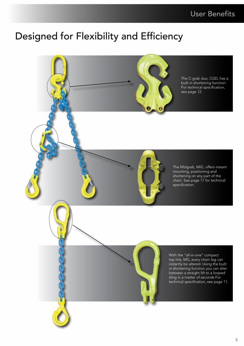
User Benefits
The Midgrab, MIG, offers instant mounting, positioning and shortening on any part of the chain. See page 17 for technical specification.
Designed for Flexibility and Efficiency
The C-grab duo, CGD, has a built in shortening function. For technical specification, see page 12.
With the "all-in-one" compact top link, MG, every chain leg can instantly be altered. Using the built in shortening function you can alter between a straight lift to a looped sling in a matter of seconds For technical specification, see page 11.
6
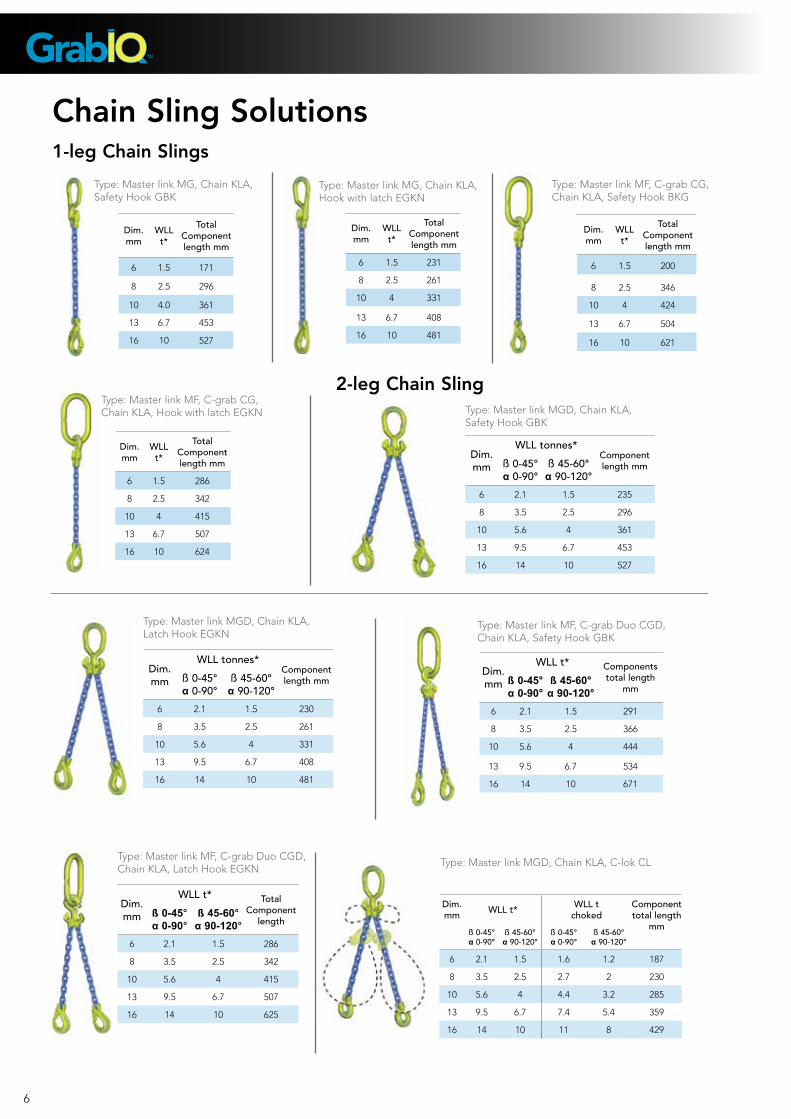
Chain Sling Solutions1-leg Chain Slings
2-leg Chain Sling
Dim.mm
WLL t*
Total Component length mm
6 1.5 231
8 2.5 261
10 4 331
13 6.7 408
16 10 481
Type: Master link MG, Chain KLA, Safety Hook GBK
Type: Master link MGD, Chain KLA, Safety Hook GBK
Type: Master link MGD, Chain KLA, Latch Hook EGKN
Type: Master link MG, Chain KLA, Hook with latch EGKN
Type: Master link MF, C-grab CG, Chain KLA, Safety Hook BKG
Type: Master link MF, C-grab CG, Chain KLA, Hook with latch EGKN
Dim. mm
WLL t*
Total Component length mm
6 1.5 171
8 2.5 296
10 4.0 361
13 6.7 453
16 10 527
Dim. mm
WLL t*
TotalComponentlength mm
6 1.5 200
8 2.5 346
10 4 424
13 6.7 504
16 10 621
Dim. mm
WLL t*
TotalComponent length mm
6 1.5 286
8 2.5 342
10 4 415
13 6.7 507
16 10 624
Dim. mm
WLL tonnes*Component length mmß 0-45°
α 0-90°ß 45-60°
α 90-120°
6 2.1 1.5 235
8 3.5 2.5 296
10 5.6 4 361
13 9.5 6.7 453
16 14 10 527
Dim. mm
WLL tonnes*Component length mmß 0-45°
α 0-90°ß 45-60°
α 90-120°
6 2.1 1.5 230
8 3.5 2.5 261
10 5.6 4 331
13 9.5 6.7 408
16 14 10 481
Type: Master link MF, C-grab Duo CGD, Chain KLA, Safety Hook GBK
Type: Master link MF, C-grab Duo CGD, Chain KLA, Latch Hook EGKN
Dim. mm
WLL t* Components total length
mmß 0-45° α 0-90°
ß 45-60° α 90-120°
6 2.1 1.5 291
8 3.5 2.5 366
10 5.6 4 444
13 9.5 6.7 534
16 14 10 671
Dim. mm
WLL t* TotalComponent
lengthß 0-45° α 0-90°
ß 45-60° α 90-120°
6 2.1 1.5 286
8 3.5 2.5 342
10 5.6 4 415
13 9.5 6.7 507
16 14 10 625
Type: Master link MGD, Chain KLA, C-lok CL
Dim. mm WLL t* WLL t
chokedComponent total length
mmß 0-45° α 0-90°
ß 45-60° α 90-120°
ß 0-45° α 0-90°
ß 45-60° α 90-120°
6 2.1 1.5 1.6 1.2 187
8 3.5 2.5 2.7 2 230
10 5.6 4 4.4 3.2 285
13 9.5 6.7 7.4 5.4 359
16 14 10 11 8 429
7
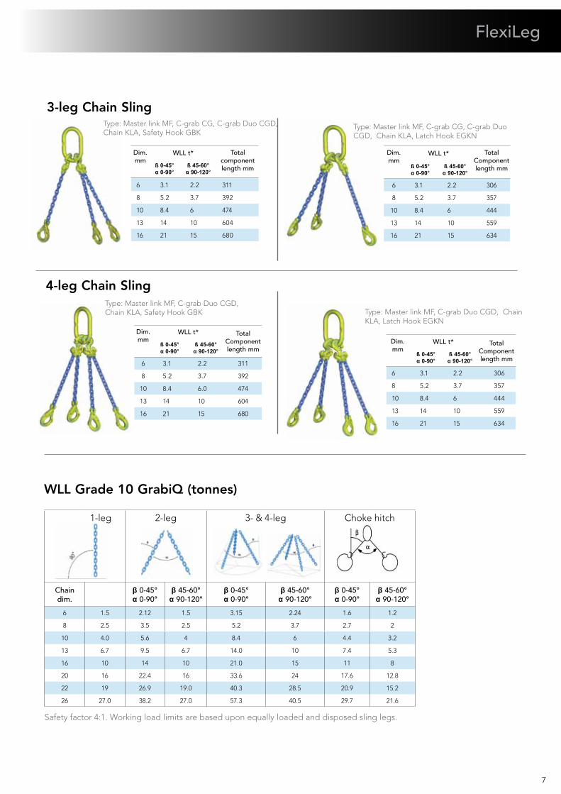
FlexiLeg
3-leg Chain Sling
4-leg Chain Sling
Dim. mm
WLL t* Totalcomponentlength mmß 0-45°
α 0-90°ß 45-60°
α 90-120°
6 3.1 2.2 311
8 5.2 3.7 392
10 8.4 6 474
13 14 10 604
16 21 15 680
Type: Master link MF, C-grab CG, C-grab Duo CGD, Chain KLA, Safety Hook GBK
Type: Master link MF, C-grab CG, C-grab Duo CGD, Chain KLA, Latch Hook EGKN
Dim. mm
WLL t* TotalComponent length mmß 0-45°
α 0-90°ß 45-60°
α 90-120°
6 3.1 2.2 306
8 5.2 3.7 357
10 8.4 6 444
13 14 10 559
16 21 15 634
Dim. mm
WLL t* TotalComponent length mm
ß 0-45° α 0-90°
ß 45-60° α 90-120°
6 3.1 2.2 306
8 5.2 3.7 357
10 8.4 6 444
13 14 10 559
16 21 15 634
Type: Master link MF, C-grab Duo CGD, Chain KLA, Safety Hook GBK Type: Master link MF, C-grab Duo CGD, Chain
KLA, Latch Hook EGKNDim. mm
WLL t* TotalComponent length mm
ß 0-45° α 0-90°
ß 45-60° α 90-120°
6 3.1 2.2 311
8 5.2 3.7 392
10 8.4 6.0 474
13 14 10 604
16 21 15 680
WLL Grade 10 GrabiQ (tonnes)
1-leg 2-leg 3- & 4-leg Choke hitch
Chain dim.
β 0-45° α 0-90°
β 45-60° α 90-120°
β 0-45° α 0-90°
β 45-60° α 90-120°
β 0-45° α 0-90°
β 45-60° α 90-120°
6 1.5 2.12 1.5 3.15 2.24 1.6 1.2
8 2.5 3.5 2.5 5.2 3.7 2.7 2
10 4.0 5.6 4 8.4 6 4.4 3.2
13 6.7 9.5 6.7 14.0 10 7.4 5.3
16 10 14 10 21.0 15 11 8
20 16 22.4 16 33.6 24 17.6 12.8
22 19 26.9 19.0 40.3 28.5 20.9 15.2
26 27.0 38.2 27.0 57.3 40.5 29.7 21.6
Safety factor 4:1. Working load limits are based upon equally loaded and disposed sling legs.
8
GrabiQ FlexiLeg – a total of 5 legs replaces the total of 10 legs with the old traditional system.
Less is More with FlexiLeg™
Old system - 10 legs in 4 separate chain slings.
1 - 2 - 3 - 4
FlexiLeg is a solution that allows you to have an instant leg shift. One single master link and a combination of five legs replace four complete slings, a total of ten legs, with the traditional system. By using the unique features of the GrabiQ range, Gunnebo Lifting has increased the flexibility even further.
Why do you want instant leg-shift?
Related products
» It will enable the user to change slings, leg by leg, which will make it lighter and easier to work with.
» Sling legs that are not being used, can easily be removed and thereby increasing safety at the work site.
» The quantity of sling material is greatly reduced, which is cost saving.
» The chain sling can be rebuilt on site, increasing the efficiency.
QuickPin - For safe exchange of sling legs
» Fits all C-components! (CL, CLD, CG, CGD)
» Has instant close/open function, no tools needed!
» Easy to retro-fit!
» Made of stainless steel for long product life span.
FlexiTag - For every GrabiQ sling
» Specially designed for FlexiLeg
» Fits all other GrabiQ slings
» WLL and chain size pre-stamped for 1 - 4
legs
» Leg angle 45/60 degree given in
contour
» Made of stainless steel for use in
all types of weather
9
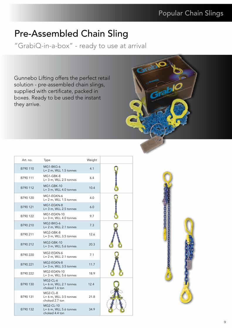
Pre-Assembled Chain Sling”GrabiQ-in-a-box” - ready to use at arrival
Gunnebo Lifting offers the perfect retail solution - pre-assembled chain slings, supplied with certificate, packed in boxes. Ready to be used the instant they arrive.
Art. no. Type Weight
B790 110 MG1-BKG-6 L= 2 m, WLL 1.5 tonnes 4.1
B790 111 MG1-GBK-8 L= 3 m, WLL 2.5 tonnes 6.4
B790 112 MG1-GBK-10 L= 3 m, WLL 4.0 tonnes 10.4
B790 120 MG1-EGKN-6 L= 2 m, WLL 1.5 tonnes 4.0
B790 121 MG1-EGKN-8 L= 3 m, WLL 2.5 tonnes 6.0
B790 122 MG1-EGKN-10 L= 3 m, WLL 4.0 tonnes 9.7
B790 210 MG2-BKG-6 L= 2 m, WLL 2.1 tonnes 7.3
B790 211 MG2-GBK-8 L= 3 m, WLL 3.5 tonnes 12.6
B790 212 MG2-GBK-10 L= 3 m, WLL 5.6 tonnes 20.3
B790 220 MG2-EGKN-6 L= 2 m, WLL 2.1 tonnes 7.1
B790 221 MG2-EGKN-8 L= 3 m, WLL 3.5 tonnes 11.7
B790 222 MG2-EGKN-10 L= 3 m, WLL 5.6 tonnes 18.9
B790 130 MG2-CL-6 L= 6 m, WLL 2.1 tonnes choked 1.6 ton
12.4
B790 131MG2-CL-8 L= 6 m, WLL 3.5 tonnes choked 2.7 ton
21.8
B790 132MG2-CL-10 L= 6 m, WLL 5.6 tonnes choked 4.4 ton
34.9
Popular Chain Slings
* Safety factor 4:1All measurements in mm10
Chain Grade 10 Short link, KL
Art. no. Box Code WLL
tonnes
D nom. mm
L »
mm
E »
mm
Weightkgs/m
MPFkN
BreakingforcekN
Z801909 - 2x200 m KLA 6-10 1.5 6 18 8 0.8 37 60
Z801915 - 3x100 m KLA 8-10 2.5 8 24 11 1.4 62.5 100
Z801921 - 2x100 m KLA 10-10 4 10 30 14 2.3 100 160
Z801927 - 1x125 m KLA 13-10 6.7 13 39 18 3.8 162 260
Z801930 - 1x 92 m KLA 16-10 10 16 48 22 5.6 250 402
Z802071 - 1 x 30.5 m KLA 20-10 16 20 60 29 9.4 393 630
Z802246 - 1 x 50 m KLA 22-10 19 22 66 31 11.8 475 806
Z802248 - 1 x 50 m KLA 26-10 27 26 78 37 14.6 664 1062
Heat treatment Quenched and tempered.Note! For chain grade 10 the maximumin service temperature is 200°C.
E
D
L
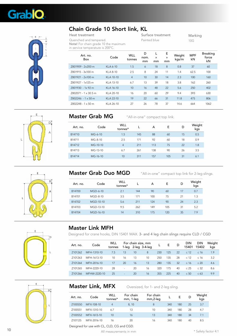
Master Grab MG ”All-in-one” compact top link.
Master Grab Duo MGD ”All-in-one” compact top link for 2-leg slings.
Art. no. Code WLLtonnes* L A E D Weight
kgs
B14700 MGD-6-10 2.1 144 90 60 17 0.7
B14701 MGD-8-10 3.5 171 100 75 21 1.3
B14702 MGD-10-10 5.6 211 124 90 24 2.3
B14703 MGD-13-10 9.5 262 149 105 31 5.2
B14704 MGD-16-10 14 310 175 120 35 7.9
Art. no. Code WLLtonnes* L A E D Weight
kgs
B14710 MG-6-10 1.5 145 88 60 15 0.5
B14711 MG-8-10 2.5 171 92 60 18 0.9
B14712 MG-10-10 4 211 113 75 22 1.8
B14713 MG-13-10 6.7 261 138 90 26 3.5
B14714 MG-16-10 10 311 157 105 31 6.1
E
D
A
L
L
A
D
E
D
L
E
Surface treatmentPainted blue
Marking10G
Art. no. Code WLLtonnes
For chain size, mm 1-leg 2-leg 3-4-leg L E D DIN
15401DIN
15402Weight
kgs
Z101262 MFH-1310-10 7.5 13 10 8 230 125 22 ≤ 12 ≤ 16 1.9
Z101263 MFH-1613-10 10 16 13 10 250 135 28 ≤ 12 ≤ 16 3.2
Z101264 MFH-2016-10 17 20 16 13 280 135 32 ≤ 16 ≤ 20 4.6
Z101265 MFH-2220-10 28 - 20 16 320 175 40 ≤ 25 ≤ 32 8.6
Z101266 MFHW-2220-10 25 - 20 16 355 225 40 ≤ 50 ≤ 63 9.9
Master Link MFHDesigned for crane hooks, DIN 15401 MAX. 3- and 4 leg chain slings require CLD / CGD
Master Link, MFX Oversized, for 1- and 2-leg sling.
Art. no. Code WLL tonnes*
For chain mm, 1-leg
For chain mm,2-leg L E D Weight
kgs
Z100550 MFX-108-10 4 8, 10 8 340 180 25 3.7
Z100551 MFX-1310-10 6.7 13 10 340 180 28 4.7
Z100552 MFX-1613-10 10 16 13 340 180 34 7.1
Z101125 MFX-2016-10 16 20 16 340 180 40 8.5
Designed for use with CL, CLD, CG and CGD.
D
L
E
* Safety factor 4:1 All measurements in mm* Safety factor 4:1 11
Components
D
L
E
Art. no. Code WLLtonnes*
For chain size, mmL E D Weight
kgs1-leg 2-leg 3-4-leg
B14487 MF-6-10 1.25 6 100 60 11 0.2
B14481 MF-86-10 2.5 6, 8 6 - 125 70 14 0.4
B14482 MF-108-10 4 10 8 6 140 80 17 0.8
B14483 MF-1310-10 7.5 13 10 8 160 95 22 1.5
B14484 MF-1613-10 10 16 13 10 190 110 28 2.8
B14485 MF-2016-10 17 20 16 13 240 140 34 5.2
B14486 MF-2220-10 25 22 20 16 250 150 40 7.3
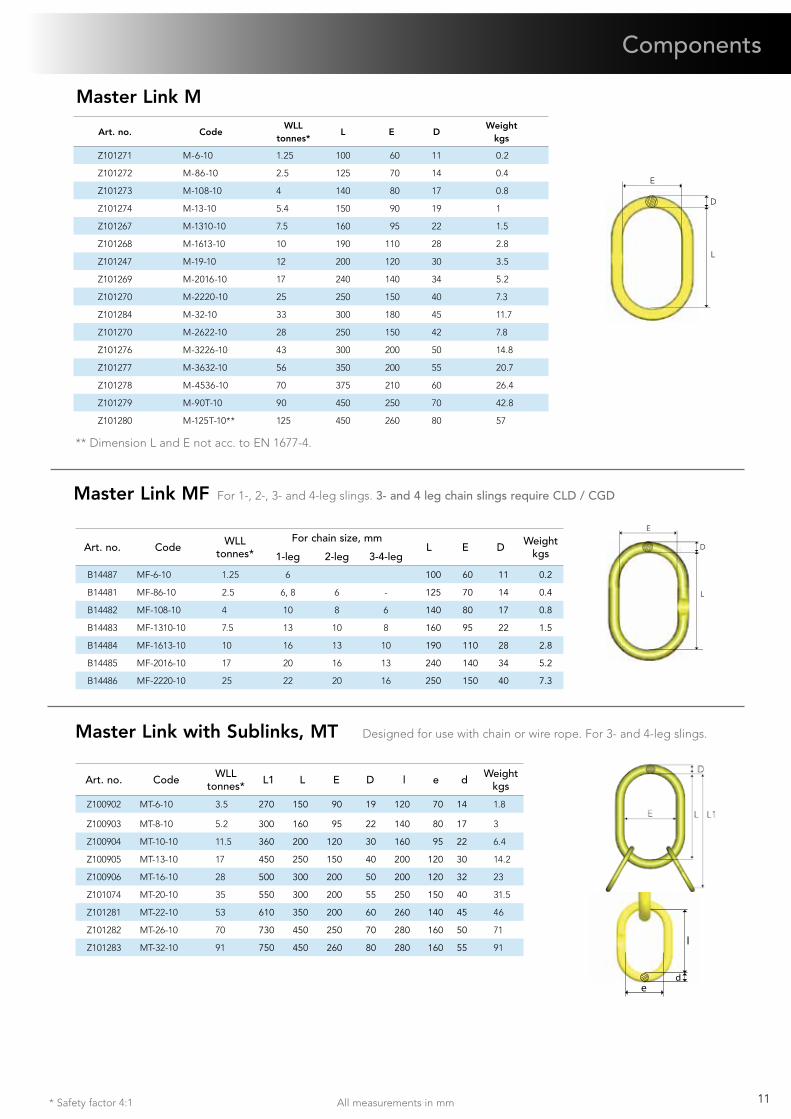
Master Link M
D
L
E
Art. no. CodeWLL
tonnes*L E D
Weight kgs
Z101271 M-6-10 1.25 100 60 11 0.2
Z101272 M-86-10 2.5 125 70 14 0.4
Z101273 M-108-10 4 140 80 17 0.8
Z101274 M-13-10 5.4 150 90 19 1
Z101267 M-1310-10 7.5 160 95 22 1.5
Z101268 M-1613-10 10 190 110 28 2.8
Z101247 M-19-10 12 200 120 30 3.5
Z101269 M-2016-10 17 240 140 34 5.2
Z101270 M-2220-10 25 250 150 40 7.3
Z101284 M-32-10 33 300 180 45 11.7
Z101270 M-2622-10 28 250 150 42 7.8
Z101276 M-3226-10 43 300 200 50 14.8
Z101277 M-3632-10 56 350 200 55 20.7
Z101278 M-4536-10 70 375 210 60 26.4
Z101279 M-90T-10 90 450 250 70 42.8
Z101280 M-125T-10** 125 450 260 80 57
** Dimension L and E not acc. to EN 1677-4.
Master Link MF For 1-, 2-, 3- and 4-leg slings. 3- and 4 leg chain slings require CLD / CGD
Master Link with Sublinks, MT Designed for use with chain or wire rope. For 3- and 4-leg slings.
Art. no. Code WLLtonnes* L1 L E D l e d Weight
kgs
Z100902 MT-6-10 3.5 270 150 90 19 120 70 14 1.8
Z100903 MT-8-10 5.2 300 160 95 22 140 80 17 3
Z100904 MT-10-10 11.5 360 200 120 30 160 95 22 6.4
Z100905 MT-13-10 17 450 250 150 40 200 120 30 14.2
Z100906 MT-16-10 28 500 300 200 50 200 120 32 23
Z101074 MT-20-10 35 550 300 200 55 250 150 40 31.5
Z101281 MT-22-10 53 610 350 200 60 260 140 45 46
Z101282 MT-26-10 70 730 450 250 70 280 160 50 71
Z101283 MT-32-10 91 750 450 260 80 280 160 55 91l
de
* Safety factor 4:1All measurements in mm12
Coupling Link G
Art. no. Code WLLtonnes* L E F C Weight
kgs
Z100821 G-6-10 1.5 45 15 8 16 0.1
Z100822 G-8-10 2.5 56 18 9 22 0.2
Z100823 G-10-10 4 68 25 12 26 0.3
Z100824 G-13-10 6.7 89 29 15 33 0.7
Z100825 G-16-10 10 106 36 19 40 1.4
Z101119 G-20-10 16 125 43 23 44 2.2
Z101339 G-22-10 20 152 50 26 59 3.5
Z101365 G-26-10 27 161 58 33 61 5.7
F
B
C
L
C-Grab CG For use with master link, eye hooks and choke.E
L
D
B
Art. no. Code WLLtonnes* L B E D Weight
kgs
B14730 CG-6-10 1.5 80 11 24 19 0.3
B14731 CG-8-10 2.5 107 12 32 24 0.7
B14732 CG-10-10 4 134 15 40 29 1.5
B14733 CG-13-10 6.7 172 18 52 38 3.2
B14734 CG-16-10 10 215 22 64 47 6.1
C-Grab CGD For use with master links.E
D
LB
Art. no. Code WLL tonnes* L B E D Weight
kgs
B14720 CGD-6-10 2.1 79 11 24 20 0.6
B14721 CGD-8-10 3.5 107 12 32 29 1.1
B14722 CGD-10-10 5.6 134 15 40 37 2.2
B14723 CGD-13-10 9.5 173 19 48 48 5.4
B14724 CGD-16-10 14 215 22 64 57 9.1
C-Lok CL For use with master links, eye hooks and choke.
Art. no. Code WLLtonnes* L B E D Weight
kgs
B14750 CL-6-10 1.5 43 11 24 18 0.2
B14751 CL-8-10 2.5 58 12 32 24 0.5
B14752 CL-10-10 4 74 15 40 29 1.0
B14753 CL-13-10 6.7 94 18 52 38 2.0
B14754 CL-16-10 10 119 22 64 48 3.8
D
C-Lok CLD For use with master links.
Art. no. Code WLLtonnes* L B E D Weight
kgs
B14740 CLD-6-10 2.1 43 11 24 22 0.4
B14741 CLD-8-10 3.5 58 12 32 29 0.6
B14742 CLD-10-10 5.6 74 15 40 37 1.2
B14743 CLD-13-10 9.5 94 18 52 46 3.1
B14744 CLD-16-10 14 119 25 64 57 5.5
D
* Safety factor 4:1 All measurements in mm* Safety factor 4:1 13
Safety Hook GBK
Art. no. Code WLLtonnes* L B G H Weight
kgs
Z100758 GBK-6-10 1.5 87 26 15 17 0.4
Z100759 GBK-8-10 2.5 119 36 20 22 0.8
Z100760 GBK-10-10 4 150 47 22 29 1.4
Z100761 GBK-13-10 6.7 172 53 29 38 2.7
Z100762 GBK-16-10 10 208 68 30 45 4.4
Safety Hook BKG
Art. no. Code WLL tonnes* L B G H Weight
kgs
Z101110 BKG-6-10 1.5 91 29 15 21 0.5
Z101100 BKG-8-10 2.5 121 37 17 26 0.9
Z101026 BKG-10-10 4 144 45 21 31 1.5
Z101034 BKG-13-10 6.7 180 55 30 40 3.0
Z101042 BKG-16-10 10 219 62 37 50 5.5
Z101091 BKG-20-10 16 240 68 44 62 9.6
Safety Hook OBK
Art. no. Code WLLtonnes* A L B E F G H Weight
kgs
Z101048 OBK-6-10 1.5 12 103 26 22 9 15 17 0.4
Z101143 OBK-7/8-10 2.5 14 139 37 28 10 20 22 0.8
Z101145 OBK-10-10 4 16 170 47 34 13 22 29 1.3
Z101147 OBK-13-10 6.7 21 206 53 44 15 29 38 2.6
Z101141 OBK-16-10 10 26 251 68 56 19 29 45 4.4
Z101240 OBK-18/20-10 16 28 293 74 60 22 44 56 7.3
A
Safety Hook BK
Art. no. Code WLLtonnes* A L B E F G H Weight
kgs
Z101108 BK-6-10 1.5 12 109 29 22 10 15 21 0.5
Z101097 BK-7/8-10 2.5 14 138 37 28 11 17 26 0.9
Z101024 BK-10-10 4.0 16 168 45 34 13 21 31 1.5
Z101032 BK-13-10 6.7 20 207 55 44 16 30 40 3.0
Z101040 BK-16-10 10 26 254 62 56 20 37 50 5.5
Z101089 BK-18/20-10 16 30 289 68 60 22 44 62 9.0
Z101325 BK-22-10 20 32 320 80 70 24 50 62 11.3
Z101326 BK-26-10 27 35 342 100 80 25 54 68 16.5
A
Art. no. Code WLLtonnes* A L B E F G H Weight
kgs
Z101154 BKD-13-10 6.7 20 207 44 45 16 30 40 3.2
Z101155 BKD-16-10 10 26 254 48 56 20 37 50 5.8
Z101156 BKD-18/20-10 16 30 290 57 60 22 44 62 9.1
Z101215 BKD-26-8 OS 21.6 35 345 72 80 25 50 69 14.5
Safety Hook BKD The double latch BK-hook with recessed trigger.A
Components
* Safety factor 4:1All measurements in mm14
Shank Safety Hook BKT
Art. no. Code WLL tonnes* L B L1 D dmin G H Weight
kgs
Z101112 BKT-6-10 1.5 90 29 36 20 11 15 21 0.5
Z101102 BKT-7/8-10 2.5 111 37 47 24 13 17 26 0.9
Z101069 BKT-10-10 4 133 45 51 29 16 21 31 1.6
H
G
L1
L
B
D
d min = the smallest permitted shank dimension after machining.Note! After machining of the shank, proof loading must be carried out.
Swivel Safety Hook BKL
Art. no. Code WLL tonnes* L B C E A G H Weight kgs
Z101114 BKL-6-10 1.5 149 29 23 33 11 15 21 0.7
Z101104 BKL-7/8-10 2.5 183 37 27 38 12 17 26 1.2
Z101028 BKL-10-10 4 218 45 37 44 15 21 31 2.0
Z101036 BKL-13-10 6.7 282 55 49 48 19 30 40 4.0
Z101044 BKL-16-10 10 341 62 65 61 25 37 50 7.2
Z101093 BKL-18/20-10 16 368 68 70 72 31 44 62 11.4
Swivel Safety Hook with Griplatch LBK
Art. no. Code WLLtonnes* L B C E A G H Weight
kgs
Z100978 LBK-7/8-10 2.5 177 37 27 38 12 20 22 1.1
Z100960 LBK-10-10 4 214 47 37 44 15 22 29 2.0
Z100993 LBK-13-10 6.7 262 53 45 48 19 29 38 3.8
Z100995 LBK-16-10 10 324 68 66 61 25 30 45 7.1
Swivel Safety Hook BKLK with ball-bearing
Art. no. Code WLL tonnes* L B C E A G H Weight
kgs
Z101116 BKLK-6-10 1.5 149 29 24 33 11 15 21 0.7
Z101106 BKLK-7/8-10 2.5 183 37 27 38 12 17 26 1.2
Z101030 BKLK-10-10 4 218 45 35 44 15 21 31 2.0
Z101038 BKLK-13-10 6.7 280 55 45 48 19 30 40 4.0
Z101046 BKLK-16-10 10 339 62 63 61 25 37 50 7.4
Z101095 BKLK-18/20-10 16 368 68 59 72 31 44 62 11.5
Z101294 BKLK-22-10 OS 20 436 79 80 80 35 50 62 16.8
Z101295 BKLK-26-10 27 486 100 110 102 45 54 68 26
Swivel Safety Hook with Griplatch LKBK with ball-bearing
Art. no. Code WLLtonnes* L B C E A G H Weight
kgs
Z100980 LKBK-7/8-10 2.5 176 37 27 38 12 20 22 1.2
Z100962 LKBK-10-10 4 213 47 35 44 15 22 29 2.1
Z100997 LKBK-13-10 6.7 261 53 43 48 19 29 38 4.0
Z100999 LKBK-16-10 10 323 68 61 61 25 30 45 6.8
* Safety factor 4:1 All measurements in mm* Safety factor 4:1 15
Sling Hook EGK
Art. no. Code WLLtonnes* L B G H Weight
kgs
Z100915 EGK-6-10 1.5 86 28 17 20 0.4
Z100938 EGK-8-10 2.5 95 32 17 23 0.5
Z100942 EGK-10-10 4 121 41 23 31 1.0
Z100946 EGK-13-10 6.7 145 49 28 38 2.0
Z100950 EGK-16-10 10 170 61 36 46 3.8
Z101138 EGK-20-10 16 209 70 42 60 7.3
Sling Hook EGKN with latch
Art. no. Code WLLtonnes* L B G H Weight
kgs
B14460 EGKN-6-10 1.5 86 24,5 17 20 0.3
B14461 EGKN-8-10 2.5 95 28 17 23 0.5
B14462 EGKN-10-10 4 121 35 23 31 1
B14463 EGKN-13-10 6.7 145 42 28 38 2.1
B14464 EGKN-16-10 10 170 52 36 46 3.9
Z101127 EGKN-20-10 16 209 61 42 60 7.6
Grab Hook GG
Art. no. Code WLL tonnes* L B Weight
kgs
B14771 GG-8-10 2.5 57 10.5 0.4
B14772 GG-10-10 4 76 12 0.9
B14773 GG-13-10 6.7 97 16 1.8
B14774 GG-16-10 10 124 20 3.1
Z101152 GG-20-10 16 147 26 7.0
Grab Hook OG/OGN
Art. no. Code WLL tonnes* L B E F Weight
kgs
Z101301 OG-22-10 20 187 26 46 32 8.6
Z101316 OGN-22-10 20 187 26 46 32 8.8
Z101302 OG-26-10 27 228 32 55 38 14
Z101317 OGN-26-10 27 228 32 55 38 14.7
G
H
L
B
Sling Hook EK
Art. no. Code WLLtonnes* L B E F G H Weight
kgs
Z101162 EK- 6-10 1.5 94 29 22 10 17 20 0.4
Z101164 EK- 8-10 2.5 109 32 28 12 17 23 0.5
Z101166 EK-10-10 4 134 42 34 14 23 30 0.9
Z101168 EK-13-10 6.7 166 49 44 18 28 38 2.0
Z101170 EK-16-10 10 203 60 56 22 36 47 3.8
Z101306 EK-20-10 16 229.2 60 60.5 26 42 60 6.3
Z101307 EK-22-10 20 267 83 64 31 43 67 8.5
Z101308 EK-26-10 27 301 95 66 32 51 75 12.6
Components
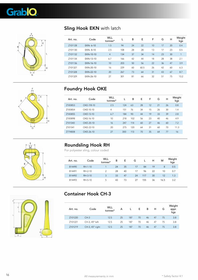
* Safety factor 4:1All measurements in mm16
L
H
B
E
G
F
Sling Hook EKN with latch
Art. no. Code WLLtonnes* L B E F G H Weight
kgs
Z101128 EKN- 6-10 1.5 94 24 22 10 17 20 0.4
Z101130 EKN- 8-10 2.5 108 28 28 13 17 23 0.5
Z101132 EKN-10-10 4 134 37 34 14 23 30 1
Z101134 EKN-13-10 6.7 166 42 44 18 28 38 2.1
Z101136 EKN-16-10 10 203 50 56 22 36 47 3.9
Z101327 EKN-20-10 16 229 60 60.5 26 42 60 6.3
Z101328 EKN-22-10 20 267 73 64 31 43 67 8.7
Z101329 EKN-26-10 27 301 81 66 32 51 75 13.2
Foundry Hook OKE
Art. no. Code WLLtonnes* L B E F G H Weight
kgs
Z100853 OKE-7/8-10 2.5 124 63 28 12 21 26 0.8
Z100854 OKE-10-10 4 151 76 34 15 26 30 1.4
Z100855 OKE-13-10 6.7 184 90 44 19 33 39 2.8
Z100898 OKE-16-10 10 218 102 56 23 40 46 4.9
Z101340 OKE-20-10 16 247 114 60 27 46 60 7.2
Z101341 OKE-22-10 20 275 120 64 31 60 70 11.3
Z774808 OKE-26-10 27 300 113 70 35 64 77 16
B
F
L
H
G
E
Art. no. Code WLLtonnes* B E G L H M Weight
kgs
B14490 RH-1-10 1 24 35 17 84 19 8 0.5
B14491 RH-2-10 2 28 40 17 96 22 10 0.7
B14492 RH-3-10 3 33 47 24 117 30 12 1.3
B14493 RH-5-10 5 43 73 27 155 36 16.5 3.2
E
M
L
H
B
Container Hook CH-3
L
E
A
B
Roundsling Hook RH For polyester sling, colour coded
Art. no. Code WLLtonnes* A L E B H G
Weight appr. kgs
Z101220 CH-3 12.5 25 187 70 46 47 75 3.8
Z101221 CH-3, 45° left 12.5 25 187 70 46 47 75 3.8
Z101219 CH-3, 45° right 12.5 25 187 70 46 47 75 3.8
* Safety factor 4:1 All measurements in mm* Safety factor 4:1 17
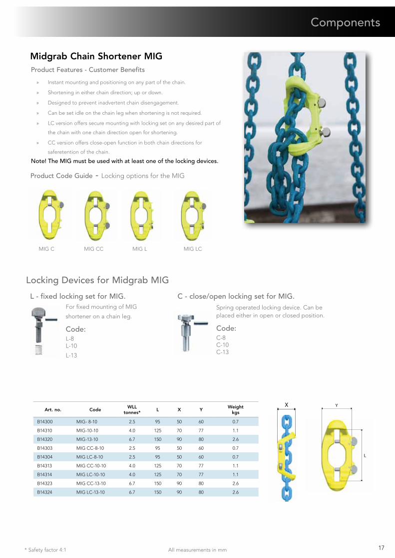
Midgrab Chain Shortener MIG
Y
L
X
Product Features - Customer Benefits
» Instant mounting and positioning on any part of the chain.
» Shortening in either chain direction; up or down.
» Designed to prevent inadvertent chain disengagement.
» Can be set idle on the chain leg when shortening is not required.
» LC version offers secure mounting with locking set on any desired part of
the chain with one chain direction open for shortening.
» CC version offers close-open function in both chain directions for
saferetention of the chain.
Note! The MIG must be used with at least one of the locking devices.
Product Code Guide - Locking options for the MIG
MIG C MIG CC
Art. no. CodeWLL
tonnes*L X Y
Weight kgs
B14300 MIG- 8-10 2.5 95 50 60 0.7
B14310 MIG-10-10 4.0 125 70 77 1.1
B14320 MIG-13-10 6.7 150 90 80 2.6
B14303 MIG CC-8-10 2.5 95 50 60 0.7
B14304 MIG LC-8-10 2.5 95 50 60 0.7
B14313 MIG CC-10-10 4.0 125 70 77 1.1
B14314 MIG LC-10-10 4.0 125 70 77 1.1
B14323 MIG CC-13-10 6.7 150 90 80 2.6
B14324 MIG LC-13-10 6.7 150 90 80 2.6
MIG L MIG LC
Spring operated locking device. Can be placed either in open or closed position.
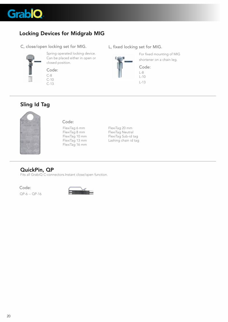
Code:C-8C-10C-13
C - close/open locking set for MIG.For fixed mounting of MIG
shortener on a chain leg.
Code: L-8L-10
L-13
L - fixed locking set for MIG.
Locking Devices for Midgrab MIG
Components
* Safety factor 4:1All measurements in mm18
Straight pull gives a higher WLL, see table. Longer bolt can be supplied on request.**Available in UNC thread; 5/16”, 3/8”, 7/16”, 5/8”, 3/4”.
180°
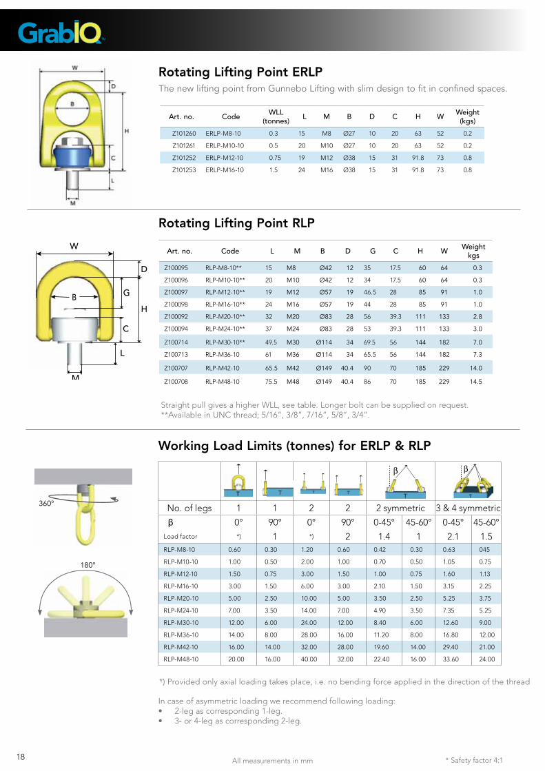
Rotating Lifting Point RLP
Rotating Lifting Point ERLP
B
L
M
D
H
G
C
W
The new lifting point from Gunnebo Lifting with slim design to fit in confined spaces.
360°
Art. no. Code L M B D G C H W Weightkgs
Z100095 RLP-M8-10** 15 M8 Ø42 12 35 17.5 60 64 0.3
Z100096 RLP-M10-10** 20 M10 Ø42 12 34 17.5 60 64 0.3
Z100097 RLP-M12-10** 19 M12 Ø57 19 46.5 28 85 91 1.0
Z100098 RLP-M16-10** 24 M16 Ø57 19 44 28 85 91 1.0
Z100092 RLP-M20-10** 32 M20 Ø83 28 56 39.3 111 133 2.8
Z100094 RLP-M24-10** 37 M24 Ø83 28 53 39.3 111 133 3.0
Z100714 RLP-M30-10** 49.5 M30 Ø114 34 69.5 56 144 182 7.0
Z100713 RLP-M36-10 61 M36 Ø114 34 65.5 56 144 182 7.3
Z100707 RLP-M42-10 65.5 M42 Ø149 40.4 90 70 185 229 14.0
Z100708 RLP-M48-10 75.5 M48 Ø149 40.4 86 70 185 229 14.5
Art. no. Code WLL(tonnes) L M B D C H W Weight
(kgs)
Z101260 ERLP-M8-10 0.3 15 M8 Ø27 10 20 63 52 0.2
Z101261 ERLP-M10-10 0.5 20 M10 Ø27 10 20 63 52 0.2
Z101252 ERLP-M12-10 0.75 19 M12 Ø38 15 31 91.8 73 0.8
Z101253 ERLP-M16-10 1.5 24 M16 Ø38 15 31 91.8 73 0.8
In case of asymmetric loading we recommend following loading:• 2-legascorresponding1-leg.• 3-or4-legascorresponding2-leg.
Working Load Limits (tonnes) for ERLP & RLP
No. of legs 1 1 2 2 2 symmetric 3 & 4 symmetric
β 0° 90° 0° 90° 0-45° 45-60° 0-45° 45-60°Load factor *) 1 *) 2 1.4 1 2.1 1.5RLP-M8-10 0.60 0.30 1.20 0.60 0.42 0.30 0.63 045
RLP-M10-10 1.00 0.50 2.00 1.00 0.70 0.50 1.05 0.75
RLP-M12-10 1.50 0.75 3.00 1.50 1.00 0.75 1.60 1.13
RLP-M16-10 3.00 1.50 6.00 3.00 2.10 1.50 3.15 2.25
RLP-M20-10 5.00 2.50 10.00 5.00 3.50 2.50 5.25 3.75
RLP-M24-10 7.00 3.50 14.00 7.00 4.90 3.50 7.35 5.25
RLP-M30-10 12.00 6.00 24.00 12.00 8.40 6.00 12.60 9.00
RLP-M36-10 14.00 8.00 28.00 16.00 11.20 8.00 16.80 12.00
RLP-M42-10 16.00 14.00 32.00 28.00 19.60 14.00 29.40 21.00
RLP-M48-10 20.00 16.00 40.00 32.00 22.40 16.00 33.60 24.00
*) Provided only axial loading takes place, i.e. no bending force applied in the direction of the thread
β β
19* Safety factor 4:1
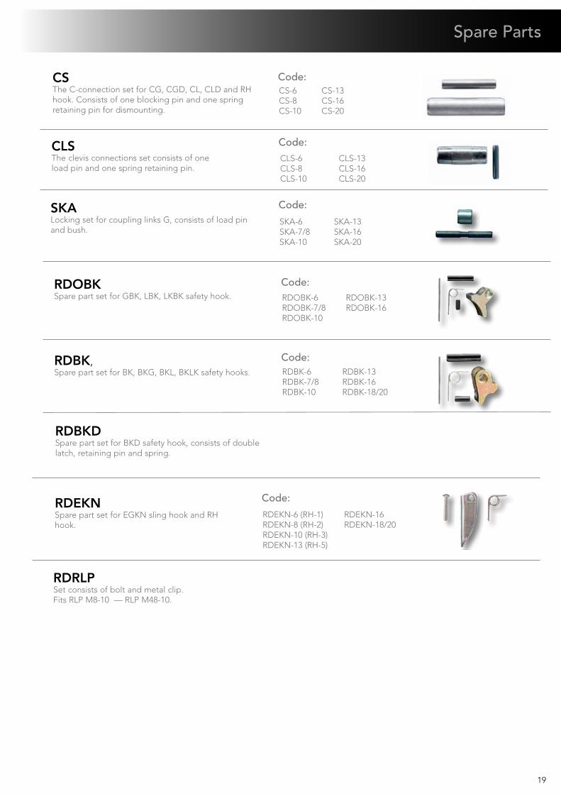
CLSThe clevis connections set consists of one load pin and one spring retaining pin.
CLS-6CLS-8CLS-10
CLS-13CLS-16CLS-20
SKALocking set for coupling links G, consists of load pin and bush.
SKA-6SKA-7/8SKA-10
SKA-13SKA-16 SKA-20
CS-6CS-8CS-10
CS-13CS-16CS-20
Spare Parts
CSThe C-connection set for CG, CGD, CL, CLD and RH hook. Consists of one blocking pin and one spring retaining pin for dismounting.
Code:
Code:
Code:
RDBK-6RDBK-7/8RDBK-10
RDBK-13RDBK-16RDBK-18/20
RDBK,Spare part set for BK, BKG, BKL, BKLK safety hooks.
Code:
RDOBKSpare part set for GBK, LBK, LKBK safety hook. RDOBK-6
RDOBK-7/8RDOBK-10
RDOBK-13RDOBK-16
Code:
RDRLPSet consists of bolt and metal clip. Fits RLP M8-10 — RLP M48-10.
RDEKN-6 (RH-1)RDEKN-8 (RH-2)RDEKN-10 (RH-3)RDEKN-13 (RH-5)
RDEKN-16RDEKN-18/20
RDEKNSpare part set for EGKN sling hook and RH hook.
RDBKDSpare part set for BKD safety hook, consists of double latch, retaining pin and spring.
Code:
20
Spring operated locking device. Can be placed either in open or closed position.
Code:C-8C-10C-13
C, close/open locking set for MIG.
For fixed mounting of MIG
shortener on a chain leg.
Code: L-8L-10
L-13
L, fixed locking set for MIG.
Locking Devices for Midgrab MIG
FlexiTag 6 mm FlexiTag 8 mm FlexiTag 10 mmFlexiTag 13 mm FlexiTag 16 mm
FlexiTag 20 mmFlexiTag NeutralFlexiTag Sub-id tagLashing chain id tag
Sling Id Tag
QP-6 -- QP-16
QuickPin, QPFits all GrabiQ C-connectors.Instant close/open function.
Code:
Code:
21
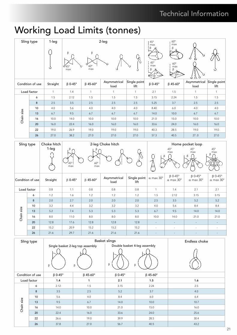
β β β β
αα
45°max
60°max
45°max
45°max
45°max
β β
β β β
60°max
45°max
60°max
45°max
β
β β
β
45°max
60°max
β β
Sling type 1-leg 2-leg
Condition of use Straight β 0-45° β 45-60°Asymmetrical
loadSingle point
liftβ 0-45° β 45-60°
Asymmetrical load
Single point lift
Load factor 1 1.4 1 1 1 2.1 1.5 1 1
Cha
in s
ize
6 1.5 2.12 1.5 1.5 1.5 3.15 2.24 1.5 1.5
8 2.5 3.5 2.5 2.5 2.5 5.25 3.7 2.5 2.5
10 4.0 5.6 4.0 4.0 4.0 8.40 6.0 4.0 4.0
13 6.7 9.5 6.7 6.7 6.7 14.0 10.0 6.7 6.7
16 10.0 14.0 10.0 10.0 10.0 21.0 15.0 10.0 10.0
20 16.0 22.4 16.0 16.0 16.0 33.6 24.0 16.0 16.0
22 19.0 26.9 19.0 19.0 19.0 40.3 28.5 19.0 19.0
26 27.0 38.2 27.0 27.0 27.0 57.3 40.5 27..0 27.0
Sling type Endless choke
Condition of use β 0-45° β 45-60° β 0-45° β 45-60°
Load factor 1.4 1 2.1 1.5 1.6
Cha
in s
ize
6 2.12 1.5 3.15 2.24 2.5
8 3.5 2.5 5.2 3.7 4.0
10 5.6 4.0 8.4 6.0 6.4
13 9.5 6.7 14.0 10.0 10.7
16 14.0 10.0 21.0 15.0 16.0
20 22.4 16.0 33.6 24.0 25.6
22 26.6 19.0 39.9 28.5 30.4
26 37.8 27.0 56.7 40.5 43.2
Sling type Choke hitch1-leg
2-leg Choke hitch Home pocket loop
Condition of use Straight β 0-45° β 45-60°Asymmetrical
loadSingle point
liftα max 30°
β 0-45°α max 30°
β 0-45°α max 30°
β 0-45°α max 30°
Load factor 0.8 1.1 0.8 0.8 0.8 1 1.4 2.1 2.1
Cha
in s
ize
6 1.2 1.6 1.2 1.2 1.2 1.5 2.12 3.15 3.15
8 2.0 2.7 2.0 2.0 2.0 2.5 3.5 5.2 5.2
10 3.2 4.4 3.2 3.2 3.2 4.0 5.6 8.4 8.4
13 5.2 7.4 5.3 5.3 5.3 6.7 9.5 14.0 14.0
16 8.0 11.0 8.0 8.0 8.0 10.0 14.0 21.0 21.0
20 12.8 17.6 12.8 12.8 12.8 - - - -
22 15.2 20.9 15.2 15.2 15.2 - - - -
26 21.6 29.7 21.6 21.6 21.6 - - - -
Single basket 2-leg top assembly Double basket 4-leg assemblyBasket slings
Working Load Limits (tonnes)
Technical Information
22
Information for Safe Use and MaintenanceThe following information aims to give advice and explain the most common questions in order to ensure safe and proper use of lifting equipment.
It is of utmost importance that this information is known to the user, and in accordance with the Machinery Directive 2006/42/EC this information must be delivered to the customer.
Extreme Temperature ConditionsThe in-service temperature effects the WLL as follows:
Upon return to normal temperature, the sling reverts to its full capacity within the above temperature range. Chain slings must not be used above or below these temperatures.
Surface TreatmentNote! Hot-dip galvanizing or plating is not allowed outside the
control of the manufacturer.
Asymmetric Loading ConditionsFor unequally loaded chain legs we recommend that the WLL’s are determined as follows:
• 2-leg slings calculated as the corresponding 1-leg sling
• 3 and 4-leg slings calculated as the corresponding 1-leg sling. (If it is certain that 2-legs are equally carrying the major part of the load, it can be calculated as the corresponding 2-leg sling)
Severe EnvironmentChain and components must not be used in alkaline (>pH10) or acidic conditions (<pH6).Comprehensive and regular examination must be carried out when used in severe or corrosive inducing environments. In
uncertain situations consult your Gunnebo Lifting dealer.
General Advice• Ensure that the received sling is precisely as ordered.
• Ensure that the manufacturer’s certificate is in order.
• Ensure that the ID-tag corresponds to the information on the certificate (the following ID tag information is compulsory: WLL, Number of chain legs, nominal size (mm) individual ID-mark, manufacturer, CE-marking and year of manufacturing).
• Ensure that all details of the chain sling are documented.
• Ensure that the staff using the chain sling has
received the appropriate information and training.
Protect Yourself and Others• Before each use the chain sling should be checked for obvious damage or deterioration.
• Know the weight of the load and the centre of gravity and ensure it is ready to move and that no obstacles will obstruct the lift.
• Check the conformity of the load with the WLL of the ID tag for the specific working configuration. Never use a sling without a legible valid ID tag!
• Prepare the landing site.
• Never overload a sling and avoid shock loading
• Never use an improper sling configuration.
• Never use a worn out or damaged sling
• Never ride on the load.
• Never stand under a suspended load.
• Take into consideration that the load may swing or rotate.• Watch your feet and fingers while loading / unloading.
Temp. of chain sling (°C)
Reduction of WLL
with Grade 8+ chain with Grade 10 chain
-40 to +200 C° 0 % 0 %+200 to +300 C° 10 % Not allowed+300 to +400 C° 25 % Not allowed
23
Method of ConnectionA chain sling is usually attached to the load and the crane by means of terminal fittings such as hooks, links etc.
Chain should be without twists or knots. The lifting point should be seated well down in the terminal fitting, never on the point or wedged in the opening. The terminal fitting should be free to incline in any direction.
The chain may be passed under or through the load to form a choke hitch or basket hitch. The chain should be allowed to assume its natural angle and should not be hammered
down.
Use edge protection to prevent sharp edges from damaging the lifting equipment. A rule of thumb is that the radius of the edge >2 x chain diameter. When lifting with chain directly on lugs we recommend that the lug diameter >9 x chain diameter. With a lug, diameter which is less than
stipulated above, the WLL must be reduced by 50%.
Home pocket loop shall have an internal loop top angle of max. 30°. Rule of thumb: Cross dimension of the load shall be max. 0.3 times the loop length (LL)
Assembly
C-connector/clevis assemblyNote: Either dismountable or permanent assembly is possible
1. Assemble the master link, C-parts and locking pin.2. Fit the retaining pin.3. Assemble the chain, clevis connection and load pin.4. Fit the retaining pin / pins.5. Make sure that the load pins and locking pins are properly secured by the retaining pins.
G-link assembly:1. Join the link halves2. Place the retaining bush between them. 3. Insert the load pin and ensure that the load pin snaps into place.
Where choke hitch is employed the WLL of the chain sling should be no more than 80% of that marked.
Definition: The home pocket is the shortening pocket of the top component directly above the clevis to which the chain is connected.
Technical Information
MaintenancePeriodic thorough examination must be carried out at least every 12 months or more frequently according to statutory regulations, type of use and past experience.1. Overloaded chain slings must be taken out of service.2. Chain and components incl. load pins which have been damaged, deformed, elongated, bent or showing signs of cracks or gauges shall be replaced. Carefully grind away small sharp cuts and burrs. Additional testing by magnetic particle inspection and/or proof loading at max. 2 x WLL may be carried out.3. Check the function of latches, triggers and retaining pins / bushes, replace when necessary. Always use Gunnebo Lifting original spare parts.4. Max. clearance between hook and latch. Note: For a Griplatch hook measure the difference between dimension A with unloaded spring and dimension A when the latch is pressed against the hook. Clearance B not applicable. 5. The wear of the chain and component shall in no place exceed 10% of the original dimensions. The chain link wear - max. 10% - is defined as the reduction of the mean diameter measured in two directions.
Size Max. A (mm). Max. B (mm). 6 2,2 3,5 7/8 2,7 4,5 10 3 6 13 3,3 7 16 4 9 20 5.5 10
D + d 0,9dn
2
^
AB A A
24
Gunnebo Industries Pty Ltd, AUSTRALIATel: +61 2 97 565 544 E-mail: [email protected] www.gunnebolifting.com
Gunnebo Industries Ltda, BRAZILTel: +55 11 4055 9800 E-mail: [email protected] www.gunnebolifting.com
Gunnebo Industries Co. LTD, P.R of CHINA (Kunshan)Tel: +86 512 5525 2200 E-mail: [email protected] www.gunnebolifting.com
Gunnebo Industries GmbH, GERMANYTel: +49 273 989 720 E-mail : [email protected] www.gunnebolifting.com
Gunnebo Industries Ltd, IRELANDTel: +353 1 4584 836 E-mail: [email protected]
Gunnebo Anja Industrier AS, NORWAYTel: +47 561 933 00 E-Mail: [email protected] www.gunnebolifting.com
Gunnebo Industries Sp.zo.o, POLANDTel: +48 552 422 926 E-mail: [email protected] www.gunnebolifting.com
Gunnebo Industries (Pty) Ltd, SOUTH AFRICATel: +27 11 614 6078 E-mail: [email protected]
Gunnebo Industrier AB, SWEDEN Tel: +46 317 643 700 E-mail: gbg@gunnebolifting .com
Gunnebo Industries Ltd, UNITED KINGDOMTel: +44 152 752 2560 E-mail: [email protected] www.gunnebolifting.com
Gunnebo Johnson Corporation, USATel: +1 918 832 8933 E-mail: [email protected] www.gunnebolifting.com
R400.E - Edition 3.1 - January 2013
Gunnebo Industrier ABTel: +46 220 384 00E-mail: [email protected]
Sales Offices