
Guido Sterbini CERN – MCS - MA Section Meeting, 8 th February 2007.
22
D0 and its D0 and its integrability integrability Guido Sterbini CERN – MCS - MA Section Meeting, 8 th February 2007
-
Upload
reynard-percival-white -
Category
Documents
-
view
215 -
download
1
Transcript of Guido Sterbini CERN – MCS - MA Section Meeting, 8 th February 2007.

D0 and its integrabilityD0 and its integrability Guido Sterbini
CERN – MCS - MA
Section Meeting, 8th February 2007

OutlineOutline1. IntroductionIntroduction
2. Potential of peak luminosity increasePotential of peak luminosity increase
3. Possible implementationsPossible implementations D0’s strengthD0’s strength
D0’s positionD0’s position
4. The main challengesThe main challengesBeam-beam effectBeam-beam effect
Energy depositionEnergy deposition
Magnet designMagnet design
5. More on energy deposition on the D0.More on energy deposition on the D0.

How can we gain a factor How can we gain a factor 1010 in LHC luminosity? in LHC luminosity?
IR focusing IR focusing strengthstrength
Xing angle Xing angle
# bunches # bunches
Beam Beam emittance emittance
# # proton/bunch proton/bunch

How can we gain a factor How can we gain a factor 1010 in LHC luminosity? in LHC luminosity?
IR focusing IR focusing strengthstrength
Xing angle Xing angle
# bunches # bunches
Beam Beam emittance emittance
# # proton/bunch proton/bunch
How can we gain a factor How can we gain a factor 1010 in LHC luminosity? in LHC luminosity?
Xing angle Xing angle

To cope with the Xing angle two solutions were presented
1. to halve s: new RF system & impact all around the LHC
2. to use crab cavities: a completely new approach
In CARE 05 was presented a new scheme:3. to use an early separation scheme.

IntroductionIntroduction
D0D1 D1TRIPLETSTRIPLETS D0
Allow a vanishing crossing angle at the IP using a dipole on each sides of the IP: the D0PROS
simple, cheap, local change, transparent to the rest of the machine.
CONS intrusion of magnetic element in the detectors
Two possible implementations the Full Early Separation scheme (FES) the Partial Early Separation scheme (PES).

IntroductionIntroduction
D0 D0
The Full Early Separation scheme (FES)
The Partial Early Separation scheme (PES)
D0 D0
We need a residual crossing angle

8 T m = Value taken into consideration so far
Which field do we need?Which field do we need?
We consider a D0’s kick of 160 rad and the value of 8 Tm is our reference value.
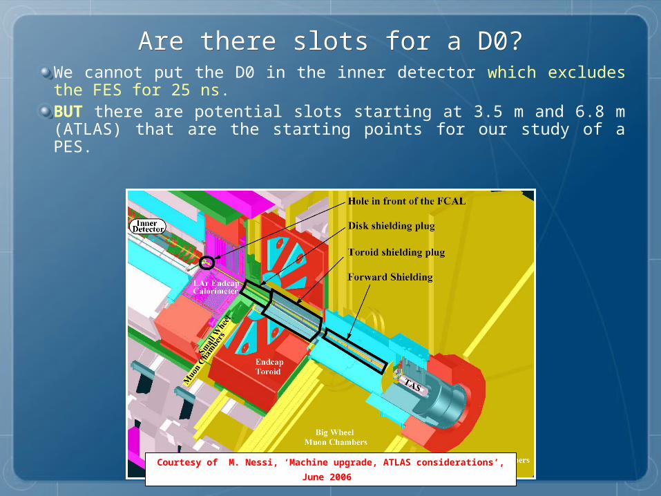
Are there slots for a D0?Are there slots for a D0?We cannot put the D0 in the inner detector which excludes the FES for 25 ns.BUT there are potential slots starting at 3.5 m and 6.8 m (ATLAS) that are the starting points for our study of a PES.
Courtesy of M. Nessi, ‘Machine upgrade, ATLAS considerations’,
June 2006

Where would we put the D0 in ATLAS?Where would we put the D0 in ATLAS?

The same strategy in CMSThe same strategy in CMS

Important issues to studyImportant issues to studyBeam-Beam interaction (experiment!)Energy deposition and backscatteringRoom for services’ routing and maintenance.Mechanical aspects (forces and torques)
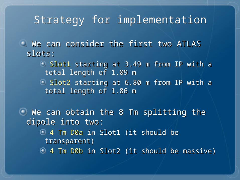
Strategy for implementationStrategy for implementation
We can consider the first two ATLAS slots:We can consider the first two ATLAS slots: Slot1Slot1 starting at 3.49 m from IP with a total starting at 3.49 m from IP with a total length of 1.09 m length of 1.09 m
Slot2Slot2 starting at 6.80 m from IP with a total starting at 6.80 m from IP with a total length of 1.86 m length of 1.86 m
We can obtain the 8 Tm splitting the We can obtain the 8 Tm splitting the dipole into two:dipole into two:
4 Tm D0a4 Tm D0a in Slot1 (it should be transparent) in Slot1 (it should be transparent)
4 Tm D0b4 Tm D0b in Slot2 (it should be massive) in Slot2 (it should be massive)

Slot1 ATLASSlot1 ATLAS
• Small volume available
• Forward calorimeter performance to be evaluated
• Magnet services routing ?
• Activation problem ?
Courtesy of M. Nessi, ‘Machine upgrade, ATLAS considerations’,
June 2006

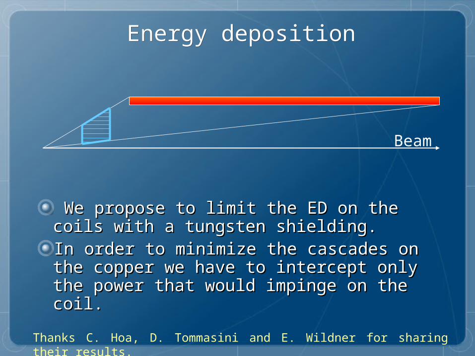
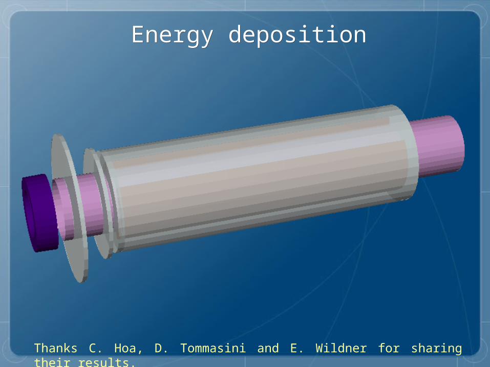
Energy depositionEnergy deposition
Thanks C. Hoa, D. Tommasini and E. Wildner for sharing their results.
LIMIT

Energy depositionEnergy deposition
Thanks C. Hoa, D. Tommasini and E. Wildner for sharing their results.
LIMIT
Energy depositionEnergy deposition
Thanks C. Hoa, D. Tommasini and E. Wildner for sharing their results.
We propose to limit the ED on the coils We propose to limit the ED on the coils with a tungsten shielding.with a tungsten shielding.In order to minimize the cascades on the In order to minimize the cascades on the copper we have to intercept only the copper we have to intercept only the power that would impinge on the coil.power that would impinge on the coil.
Beam

Energy depositionEnergy deposition
Thanks C. Hoa, D. Tommasini and E. Wildner for sharing their results.
LIMIT

Energy depositionEnergy deposition
Thanks C. Hoa, D. Tommasini and E. Wildner for sharing their results.
LIMIT
Energy depositionEnergy deposition
Thanks C. Hoa, D. Tommasini and E. Wildner for sharing their results.
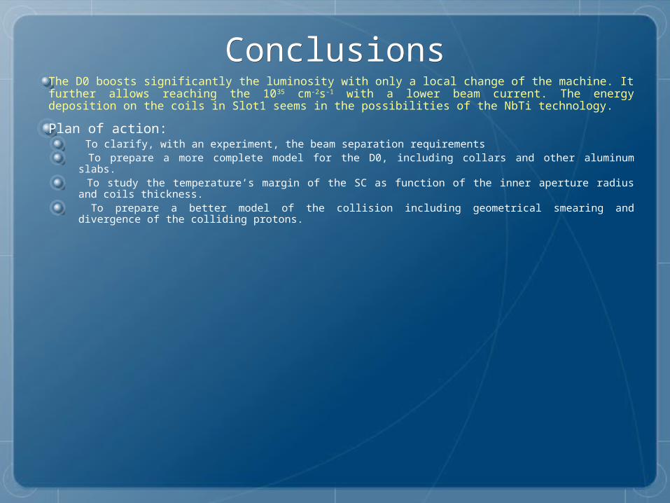
ConclusionsConclusionsThe D0 boosts significantly the luminosity with only a local change of the machine. It further allows reaching the 1035 cm-2s-1 with a lower beam current. The energy deposition on the coils in Slot1 seems in the possibilities of the NbTi technology.
Plan of action: To clarify, with an experiment, the beam separation requirements To prepare a more complete model for the D0, including collars and other aluminum slabs. To study the temperature’s margin of the SC as function of the inner aperture radius and coils thickness. To prepare a better model of the collision including geometrical smearing and divergence of the colliding protons.