Guidelines On Laser Scanning In Plant Design - Fraunhofer · Guidelines on laser scanninG in Plant...
22
GUIDELINES ON LASER SCANNING IN PLANT DESIGN FRAUNHOFER INSTITUTE FOR FACTORY OPERATION AND AUTOMATION IFF, MAGDEBURG PREPARATION AND EXECUTION OF LASER SCANNING PROJECTS FOR INDUSTRIAL PLANT DESIGN AND DOCUMENTATION
Transcript of Guidelines On Laser Scanning In Plant Design - Fraunhofer · Guidelines on laser scanninG in Plant...

Guidelines on laser scanninG in Plant desiGn
F r a u n h o F e r I n s t I t u t e F o r F a c t o r y o p e r at I o n a n d a u t o m at I o n I F F, m a g d e b u r g
PreParation and execution of laser scanninG Projects for industrial Plant desiGn and documentation

Guidelines on Laser Scanning in Plant Design 2015, third edition | 3
contents
1 Introduction 4
2 LaserScanningProjectSpecifications(TechnicalSpecifications) 5
2.1 SpecificationoftheProject 4
2.2 SpecificationofScanAreas 6
2.3 GeneralGuidelines 6
2.4 LaserScanningGuidelines 6
2.5 DataFormatandDataDelivery 8
2.6 Nondisclosure 9
3 ExecutionofLaserScanningProjects(TechnicalSpecifications) 9
3.1 GeneralInformation 9
3.2 DescriptionoftheProjectWorkflow 10
3.3 DataDelivery 11
3.4 costs 12
3.5 ImportantInformation 12
3.6 OptionalServices 12
3.7 References 13
4 Glossary 14
Acknowledgements 20
EditorialNotes 22
4 | Guidelines on Laser Scanning in Plant Design 2015, third edition
L a s e r s c a n n I n g I n d e r a n L a g e n p L a n u n g u n d I m a n L a g e n b a u
1 introduction
In recent years, laser scanning has become established as an
efficient method of data capture in the field of plant design
and construction and is increasingly supplanting conven-
tional scanning methods. As it stands, laser scanning can be
expected to become the industry standard of industrial plant
surveying. This technology is increasingly spreading because
it is fast, cost effective and highly precise. Instead of taking
discrete individual measurements, this technology practically
maps the planning area entirely. Projects can generally be
completed faster and better when laser scanning is used. This
cuts costs considerably.
This is why laser scanning service providers are increasingly
being contracted to scan plants or sections of them and thus
generate digital as-built documentation with point clouds.
Point clouds are used, for example, as the basis for 3D model-
ing, collision detection, reverse engineering and virtual reality
applications. This makes it extremely important for clients and
laser scanning service providers to set the basic objectives of
laser scanning. Such objectives both facilitate the compilation
of appropriate as-built documentation and meet clients’ de-
mand for high quality data. These guidelines identify impor-
tant objectives.
The first section of these guidelines specifies the information
clients have to provide to laser scanning service providers to
enable them to prepare a precise and suitable quotation
(Section 2). The second section examines the stipulations on
technical specifications (quotation) that meet the demands
in plant design and construction (Section 3). The final section
presents and explains laser scanning terminology (Section 4).
Although the structures and contents presented in the second
and third sections can be adopted for the compilation of
technical and requirements specifications, it is expedient to
modify them for individual needs.
These guidelines were compiled by the industry working group
“Laserscanning und Virtual Reality im Anlagebau” (“Laser
Scanning and Virtual Reality in Plant Design”) and constitute
a recommendation for laser scanning in plant design and
construction. They are intended to furnish a sound basis for
the compilation of technical specifications (requests for
quotations) and requirements specifications (quotations).
These guidelines are neither intended to lessen communica-
tion between clients and service providers nor to supplant
service providers’ guidance.
Guidelines on Laser Scanning in Plant Design 2015, third edition | 5
L a s e r s c a n n I n g I n d e r a n L a g e n p L a n u n g u n d I m a n L a g e n b a u
This section presents the standard contents of technical
specifications, which provide essential information to service
providers when laser scanning is being contracted. This
information enables service providers to prepare accurate and
suitable quotations and additionally facilitates communication
with service providers.
2.1 SpecificationoftheProject
The service provider is given the following information on the
project before the laser scanning commences:
– The name of the project
– A brief description of the project and the work planned in
the scan area (retrofitting, dismantlement, construction,
prefabrication, etc.)
– Names of contacts for laser scanning, site and project
management as well as their contact information, e.g.
phone numbers, email addresses and places of work
This information is often needed for on-site inspections, photo
authorizations, work permits and safety briefings.
2.2 SpecificationoftheScanArea
This section roughly defines the area to be scanned:
– The company’s address
– The name of the plant
– The description of the facilities
– A floor plan with identified scan areas
– A geographic description of the scan area, e.g. using coor-
dinates from Google Maps (link to Google Maps)
2.2.1 ExtentofDataCapture
This section specifies which objects in which areas are to be
laser scanned.
1. A detailed site plan with the scan areas indicated by color
and including
– Information on the plant/facility, sections, and pipe
racks including elevations, platforms and equipment or
pipe density
– The layout plan(s) of the scan areas
– If possible, an aerial photo with the scan areas indicated
by color
– Digital scale drawings, provided they are available
2. Photos of scan areas
– Brief description of photos – what is pictured, what
actions are planned and what requirements are imposed
on scanning.
– If necessary, with supporting identification in the photos
– Indication of each photo’s position and alignment in the
site plan can be helpful
3. Specification of whether the previously specified areas are to
be scanned completely or in spots (e.g. tie areas/points)
4. Specification of the objects to be scanned and the level of
detail:
– Piping including the smallest nominal pipe size to be
scanned (see also Section 2.4.2)
– Pipe racks including elevations
– Primary and secondary steel construction
– Adjoining buildings as volume or with interior equipment
– Equipment (pumps, containers, heat exchangers,
machines)
2 laser scanninG Project sPecification (technical sPecifications)
6 | Guidelines on Laser Scanning in Plant Design 2015, third edition
L a s e r s c a n n I n g I n d e r a n L a g e n p L a n u n g u n d I m a n L a g e n b a u
– Cable trays
– HVAC ducts
– Nonstandard components
5. Details, e.g. flange position, plant component status (actual
plant in operation, line and equipment temperatures,
ambient temperature, etc.) have to be specified for pipe
work intended to be highly prefabricated.
2.2.3 AccessibilityandDistinctiveFeaturesofthe
Facility
This section presents items that furnish information on the
accessibility of the facility to be scanned and its special
features.
1. Accessibility of the facility and the scan area
2. Information on the type of facility (is there protection
against the elements?), outdoor facility or enclosed building
3. General and temporal accessibility of the scan areas
4. Details on common areas and, where applicable, work
conditions (observance of legally required work breaks;
possibilities to store equipment or charge batteries)
5. Distinctive features of the facility
– Which areas are affected by vibrations?
– Potentially explosive scan areas (classification of
explosive zones)
– Other specifics of the atmosphere (e.g. dust,
temperature, humidity)
– Can scanning be done while the plant is running?
– What downtimes are necessary?
– Is certain safety equipment needed and who provides it?
– What training courses and safety briefings are
necessary?
– Information on whether scaffolding is present or
other constraining work such as dismantlement or
construction will be performed at the time of scanning.
– Information on whether reflective surfaces may be
sprayed opaquely to obtain better scans.
2.3 GeneralGuidelines
2.3.1 MinimumContentoftheTechnical
Specifications
The minimum content of technical specifications has to be
specified in the requirements specification. This makes it easier
to compare quotations and contract laser scanning services.
Specifying the following points has proven effective:
– Recapitulation of the request for quotations (clarity for the
contractor)
– List and itemization of the expected labor and costs
– Description of execution, if necessary with designated scan
areas including scanning period and estimated number of
laser scanner locations
– Names and qualifications of the scanner operators
– Documentation of equipment calibration
– Information on scanner capabilities (temperature range,
maximum humidity, operability in potentially explosive
atmospheres)
– Safety plan and certifications, e.g. ISO and SCC
– Quality control based on an appended quality plan
– List of services in addition to laser scanning, including prices
(e.g. difficulties, additional data formats and services, etc.)
– Retention periods of data
2.3.2 dates
The following dates have to be scheduled:
– Deadline for the submission of quotations
– Date of award of the contract
Guidelines on Laser Scanning in Plant Design 2015, third edition | 7
L a s e r s c a n n I n g I n d e r a n L a g e n p L a n u n g u n d I m a n L a g e n b a u
– Dates of scanning including duration, factoring in
operational interruptions (construction work, scaffold
building, etc.)
– Completion date of the contract
2.4 LaserScanningGuidelines
2.4.1 AccuracyStandards
The accuracy achievable is contingent on different para meters.
In general, accuracy of ≤5 mm (≤0.19 inch) can be achieved in
laser scanning for plant design and construction. When neces-
sary (custom components, fabrication of connectors, etc.),
greater accuracy can also be achieved. It is advisable to consult
with the laser scanning service provider about the achievable
accuracy. The following points have to be stipulated:
– The accuracy or tolerances required by the client
– The service provider’s estimation of achievable accuracy
2.4.2 PreparatoryWork
Before scanning, the following stipulations to be made and
communicated to the service provider:
– Piping must be stripped of insulation
– No longer needed piping and equipment must be
dismantled (if possible)
– Scaffolding and aerial work platforms must be set up if
necessary
– Unneeded scaffolding must be removed
– Control points must be established and the plant network
must be consolidated
2.4.3 ExecutionoftheLaserScanning
The service provider has to be given different scan parameters
since they directly affect the quality and accuracy of the com-
plete point cloud.
1. Specify scan resolution as a function of the areas to be
scanned and the size of the objects to be scanned (density
of scanned points on an object must be sufficient).
2. Normally, 80% of all targets are surveyed tachymetrically.
This may vary depending on the nature of the project and
when projects are small or medium in scope.
3. Anomalies during scanning have to be documented in
each scan position:
– Unfavorable weather conditions (snow, rain, etc.)
– Interference with measurements by dust or exhaust
– Vibrations or jolts
– Difficult-to-scan surface (e.g. very shiny surfaces, glass
piping, etc.)
4. Colorization of the point cloud:
– Grayscale (intensity values), standard
– Colorization using photos (panoramic images)
– Colorization using HDR images (HDR panoramic images)
– Unless photomapping is automatic, at least five dis-
persed control points should be used per scan to map
panoramic photos on point clouds.
note: The cameras integrated in advanced laser scanners
deliver high quality results. The highest quality color photos
are obtained by using an external SLR camera
8 | Guidelines on Laser Scanning in Plant Design 2015, third edition
L a s e r s c a n n I n g I n d e r a n L a g e n p L a n u n g u n d I m a n L a g e n b a u
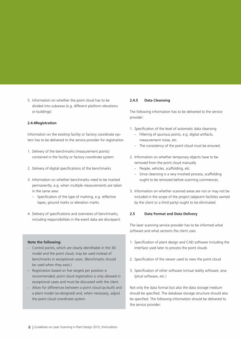
5. Information on whether the point cloud has to be
divided into subareas (e.g. different platform elevations
or buildings)
2.4.4 registration
Information on the existing facility or factory coordinate sys-
tem has to be delivered to the service provider for registration.
1. Delivery of the benchmarks (measurement points)
contained in the facility or factory coordinate system
2. Delivery of digital specifications of the benchmarks
3. Information on whether benchmarks need to be marked
permanently, e.g. when multiple measurements are taken
in the same area:
– Specification of the type of marking, e.g. reflective
tapes, ground marks or elevation marks
4. Delivery of specifications and overviews of benchmarks,
including responsibilities in the event data are discrepant.
Notethefollowing:
– Control points, which are clearly identifiable in the 3D
model and the point cloud, may be used instead of
benchmarks in exceptional cases. (Benchmarks should
be used when they exist.)
– Registration based on five targets per position is
recommended; point cloud registration is only allowed in
exceptional cases and must be discussed with the client.
– Allow for differences between a point cloud (as-built) and
a plant model (as-designed) and, when necessary, adjust
the point cloud coordinate system.
2.4.5 DataCleansing
The following information has to be delivered to the service
provider:
1. Specification of the level of automatic data cleansing
– Filtering of spurious points, e.g. digital artifacts,
measurement noise, etc.
– The consistency of the point cloud must be ensured.
2. Information on whether temporary objects have to be
removed from the point cloud manually
– People, vehicles, scaffolding, etc.
– Since cleansing is a very involved process, scaffolding
ought to be removed before scanning commences.
3. Information on whether scanned areas are not or may not be
included in the scope of the project (adjacent facilities owned
by the client or a third party) ought to be eliminated.
2.5 DataFormatandDataDelivery
The laser scanning service provider has to be informed what
software and what versions the client uses.
1. Specification of plant design and CAD software including the
interface used later to process the point clouds
2. Specification of the viewer used to view the point cloud
3. Specification of other software (virtual reality software, ana-
lytical software, etc.)
Not only the data format but also the data storage medium
should be specified. The database storage structure should also
be specified. The following information should be delivered to
the service provider:
Guidelines on Laser Scanning in Plant Design 2015, third edition | 9
L a s e r s c a n n I n g I n d e r a n L a g e n p L a n u n g u n d I m a n L a g e n b a u
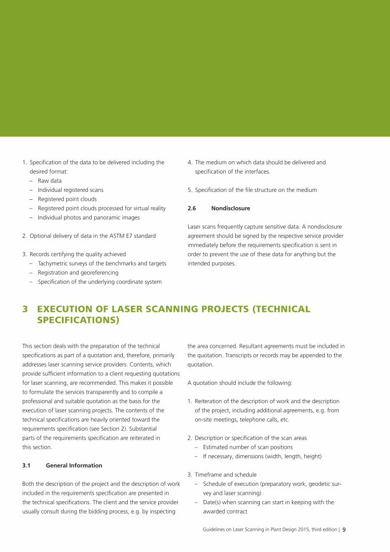
1. Specification of the data to be delivered including the
desired format:
– Raw data
– Individual registered scans
– Registered point clouds
– Registered point clouds processed for virtual reality
– Individual photos and panoramic images
2. Optional delivery of data in the ASTM E7 standard
3. Records certifying the quality achieved
– Tachymetric surveys of the benchmarks and targets
– Registration and georeferencing
– Specification of the underlying coordinate system
4. The medium on which data should be delivered and
specification of the interfaces.
5. Specification of the file structure on the medium
2.6 Nondisclosure
Laser scans frequently capture sensitive data. A nondisclosure
agreement should be signed by the respective service provider
immediately before the requirements specification is sent in
order to prevent the use of these data for anything but the
intended purposes.
3 execution of laser scanninG Projects (technical sPecifications)
This section deals with the preparation of the technical
specifications as part of a quotation and, therefore, primarily
addresses laser scanning service providers. Contents, which
provide sufficient information to a client requesting quotations
for laser scanning, are recommended. This makes it possible
to formulate the services transparently and to compile a
professional and suitable quotation as the basis for the
execution of laser scanning projects. The contents of the
technical specifications are heavily oriented toward the
requirements specification (see Section 2). Substantial
parts of the requirements specification are reiterated in
this section.
3.1 GeneralInformation
Both the description of the project and the description of work
included in the requirements specification are presented in
the technical specifications. The client and the service provider
usually consult during the bidding process, e.g. by inspecting
the area concerned. Resultant agreements must be included in
the quotation. Transcripts or records may be appended to the
quotation.
A quotation should include the following:
1. Reiteration of the description of work and the description
of the project, including additional agreements, e.g. from
on-site meetings, telephone calls, etc.
2. Description or specification of the scan areas
– Estimated number of scan positions
– If necessary, dimensions (width, length, height)
3. Timeframe and schedule
– Schedule of execution (preparatory work, geodetic sur-
vey and laser scanning)
– Date(s) when scanning can start in keeping with the
awarded contract
10 | Guidelines on Laser Scanning in Plant Design 2015, third edition
L a s e r s c a n n I n g I n d e r a n L a g e n p L a n u n g u n d I m a n L a g e n b a u
– Daily scan times
– Date of data delivery to the client
4. Names of contacts including contact information, e.g.
telephone numbers and email addresses:
– Project management
– Scanning and evaluation staff
– Qualifications and experience
5. Safety concept
– Safety plan and staff safety qualifications
– Certifications
– Scanner capabilities (temperature range, maximum
humidity, use in potentially explosive atmospheres)
– Personal protective equipment
6. Quality assurance
– Calibration records of instruments
– Quality control during the project
– Certifications
– Information on archiving of raw data and project data
– Information on the expected overall accuracy of the
registered point cloud
7. Information on privacy and nondisclosure
3.2 DescriptionoftheProjectWorkflow
This section expounds the laser scanning procedure
understandably for the client. In particular, it should
address the specific requirements of the project as well
as quality and safety standards.
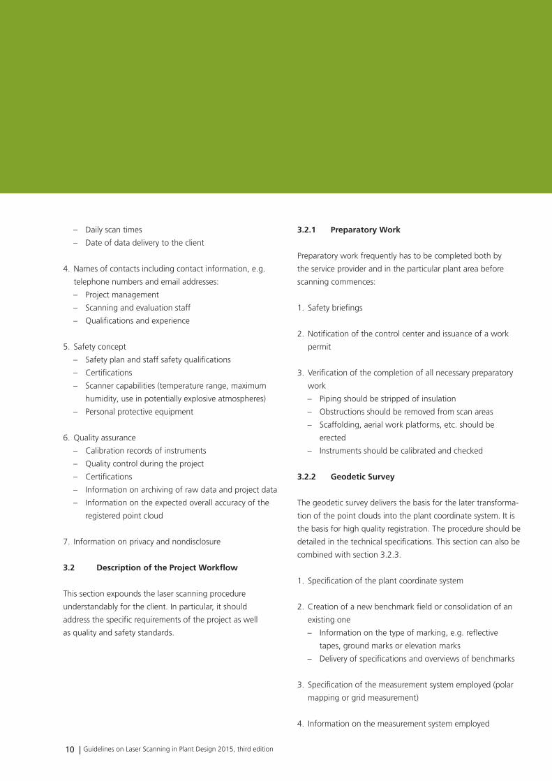
3.2.1 PreparatoryWork
Preparatory work frequently has to be completed both by
the service provider and in the particular plant area before
scanning commences:
1. Safety briefings
2. Notification of the control center and issuance of a work
permit
3. Verification of the completion of all necessary preparatory
work
– Piping should be stripped of insulation
– Obstructions should be removed from scan areas
– Scaffolding, aerial work platforms, etc. should be
erected
– Instruments should be calibrated and checked
3.2.2 GeodeticSurvey
The geodetic survey delivers the basis for the later transforma-
tion of the point clouds into the plant coordinate system. It is
the basis for high quality registration. The procedure should be
detailed in the technical specifications. This section can also be
combined with section 3.2.3.
1. Specification of the plant coordinate system
2. Creation of a new benchmark field or consolidation of an
existing one
– Information on the type of marking, e.g. reflective
tapes, ground marks or elevation marks
– Delivery of specifications and overviews of benchmarks
3. Specification of the measurement system employed (polar
mapping or grid measurement)
4. Information on the measurement system employed
Guidelines on Laser Scanning in Plant Design 2015, third edition | 11
L a s e r s c a n n I n g I n d e r a n L a g e n p L a n u n g u n d I m a n L a g e n b a u
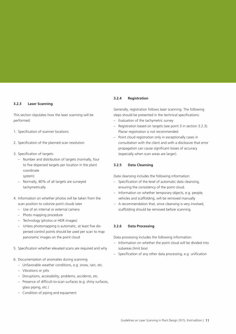
3.2.3 Laser scanning
This section stipulates how the laser scanning will be
performed:
1. Specification of scanner locations
2. Specification of the planned scan resolution
3. Specification of targets:
– Number and distribution of targets (normally, four
to five dispersed targets per location in the plant
coordinate
system)
– Normally, 80% of all targets are surveyed
tachymetrically
4. Information on whether photos will be taken from the
scan position to colorize point clouds later
– Use of an internal or external camera
– Photo mapping procedure
– Technology (photos or HDR images)
– Unless photomapping is automatic, at least five dis-
persed control points should be used per scan to map
panoramic images on the point cloud
5. Specification whether elevated scans are required and why
6. Documentation of anomalies during scanning
– Unfavorable weather conditions, e.g. snow, rain, etc.
– Vibrations or jolts
– Disruptions, accessibility, problems, accidents, etc.
– Presence of difficult-to-scan surfaces (e.g. shiny surfaces,
glass piping, etc.)
– Condition of piping and equipment
3.2.4 registration
Generally, registration follows laser scanning. The following
steps should be presented in the technical specifications:
– Evaluation of the tachymetric survey
– Registration based on targets (see point 3 in section 3.2.3).
Planar registration is not recommended.
– Point cloud registration only in exceptionally cases in
consultation with the client and with a disclosure that error
propagation can cause significant losses of accuracy
(especially when scan areas are larger).
3.2.5 DataCleansing
Data cleansing includes the following information:
– Specification of the level of automatic data cleansing,
ensuring the consistency of the point cloud.
– Information on whether temporary objects, e.g. people,
vehicles and scaffolding, will be removed manually
– A recommendation that, since cleansing is very involved,
scaffolding should be removed before scanning.
3.2.6 DataProcessing
Data processing includes the following information:
– Information on whether the point cloud will be divided into
subareas (limit box)
– Specification of any other data processing, e.g. unification
12 | Guidelines on Laser Scanning in Plant Design 2015, third edition
L a s e r s c a n n I n g I n d e r a n L a g e n p L a n u n g u n d I m a n L a g e n b a u
3.3 DataDelivery
In the quotation, the contractor should specify what data will
be delivered to the client and in what form and structure.
Ideally, given the large volume of scan data, data should
be delivered on an external hard drive. In many cases, data
formats have been specified in the requirements specification.
The delivered data and formats should be stipulated in the
technical specifications:
1. Definition of project execution, noting any unusual
occurrences
2. Geodetic survey:
– Overview of the newly established benchmark field
(overview)
– List of new benchmark coordinates with specification
of benchmarks
– Photo documentation of benchmarks
– Data processing and transfer to a factory information
system
3. Laser scanning
– Floor plan with scanner locations
– Optionally, registered scans in the stipulated data format
– Complete point cloud in the stipulated data format
– Viewer in the stipulated data format
4. Accuracy data (reports) verifying the accuracy achieved:
– Benchmark field
– Target calibration
– Registration
– Overall accuracy of the registered point cloud
– Specification of areas where this accuracy was not
achieved
5. Optional
Time sheets and records of incidents relevant to safety
3.4 costs
The costs of laser scanning can be itemized in different ways.
It is recommended to itemize costs in the technical specifica-
tions by scan area. The costs of the geodetic survey, laser
scanning, registration and data cleansing should be included.
Alternatively, costs can also be itemized as follows:
– Project preparation
– Geodetic survey
– Laser scanning
– Registration
– Data cleansing
In addition to the actual costs of the laser scan, the technical
specifications should also include travel expenses, terms of
payment and a period of validity. Additional costs that might
be incurred should also be included:
– Costs of the use of special equipment, e.g. aerial work
platforms
– Costs of the laser scanning team per day and per hour
when work is interrupted because of disruptions at the
company and when the scan area is expanded beyond the
scope of the project
– Costs of the laser scanning team when its work is
interrupted because of disruptions at the company
– Costs of optional services, e.g. reports for tie points (see
Section 3.6.)
3.5 ImportantInformation
The technical specifications should include information on the
limitations of laser scanning. Especially clients with little or no
experience working with point clouds may harbor false expec-
tations and ideas. The limitations should always be specified in
the context of the specific job rather than generally.
Guidelines on Laser Scanning in Plant Design 2015, third edition | 13
L a s e r s c a n n I n g I n d e r a n L a g e n p L a n u n g u n d I m a n L a g e n b a u
The following limitations of laser scanning should be
mentioned:
1. A scan area is never covered 100% (The goal is to scan
between 80% and 100%)
2. Errors in measurement caused by external factors
– Noise
– Digital artifacts
– External conditions, e.g. vibrations, lighting conditions
during color scans, etc.
– Highly reflective surfaces
– Absorption of laser light by black surfaces
– Difficulties scanning particular materials, e.g. glass
3. Weather conditions, e.g. rain and snow
4. Scanning of temporary spurious points, e.g. vehicles,
people, etc.
3.6 OptionalServices
Depending on the extent of the client’s experience, it may
be helpful to offer additional services. At the same time, this
raises the client’s awareness of the diversity of uses of point
clouds. It is advisable to specify the costs of such additional
services:
– Records of tie points
– Panoramic views of scans (panoramic scan viewer)
– Creation or consolidation of the benchmark system includ-
ing documentation of benchmarks overviews, specifications
of the benchmarks, lists of coordinates, etc.
– Overviews with surveyed objects in buildings or facilities
– Modeling of dumb solids
– Drafting of as-built isometric drawings
3.7 References
References from comparable projects in the previous three
years can be included in the technical specifications to give
the client an idea of the service provider’s experience.
14 | Guidelines on Laser Scanning in Plant Design 2015, third edition
L a s e r s c a n n I n g I n d e r a n L a g e n p L a n u n g u n d I m a n L a g e n b a u
4 Glossary
This section explains the laser scanning terminology employed
in these guidelines.
ASTMInternational
Formerly named the American Society for Testing and
Materials, ASTM International is an internationally recognized
market leader in the development and supply of international
voluntary consensus standards, including the E57 standard for
3D imaging systems, which applies to laser scanners.
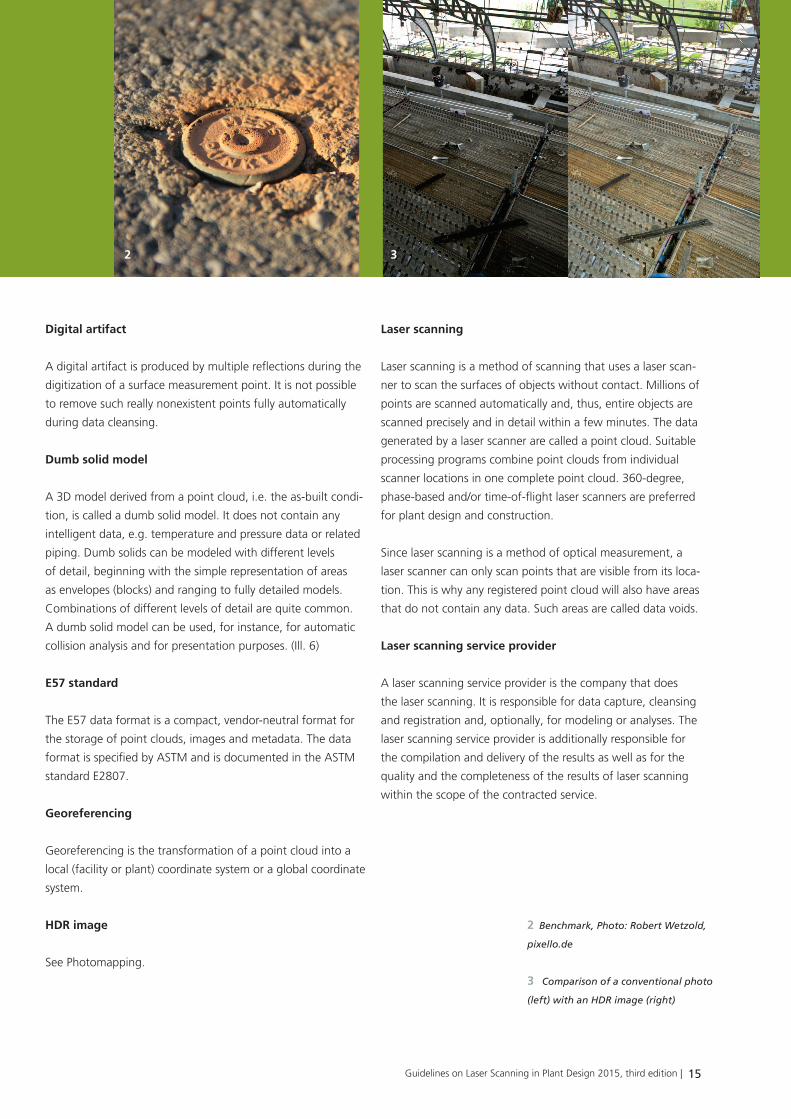
Benchmark
The conversion of scans into a local facility or plant coordinate
system necessitates engineering surveying of the scanned
facilities (tachymetric surveying). This requires benchmarks,
which are derived from the higher-level coordinate system
and have known locations and elevations. (Ill.1)
Control points can be used instead of benchmarks for trans-
formations, too. These are points that are present in both a
3D model and the point cloud. They also serve to bring the
complete point cloud and the 3D model into congruence and,
all in all, facilitate the creation of 3D models from existing
planning documents.
Controlpoint
See Benchmark.
Coordinatesystem
This is the coordinate system referenced by the registered
point cloud (complete point cloud). Normally, it is a local
reference system, e.g. a facility or plant coordinate system
or a global coordinate system (global reference system).
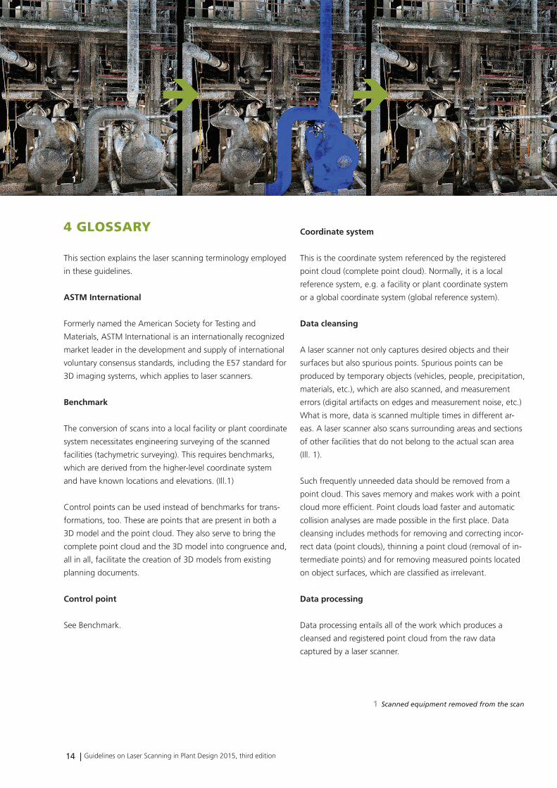
Datacleansing
A laser scanner not only captures desired objects and their
surfaces but also spurious points. Spurious points can be
produced by temporary objects (vehicles, people, precipitation,
materials, etc.), which are also scanned, and measurement
errors (digital artifacts on edges and measurement noise, etc.)
What is more, data is scanned multiple times in different ar-
eas. A laser scanner also scans surrounding areas and sections
of other facilities that do not belong to the actual scan area
(Ill. 1).
Such frequently unneeded data should be removed from a
point cloud. This saves memory and makes work with a point
cloud more efficient. Point clouds load faster and automatic
collision analyses are made possible in the first place. Data
cleansing includes methods for removing and correcting incor-
rect data (point clouds), thinning a point cloud (removal of in-
termediate points) and for removing measured points located
on object surfaces, which are classified as irrelevant.
data processing
Data processing entails all of the work which produces a
cleansed and registered point cloud from the raw data
captured by a laser scanner.
1
1 Scanned equipment removed from the scan
Guidelines on Laser Scanning in Plant Design 2015, third edition | 15
L a s e r s c a n n I n g I n d e r a n L a g e n p L a n u n g u n d I m a n L a g e n b a u
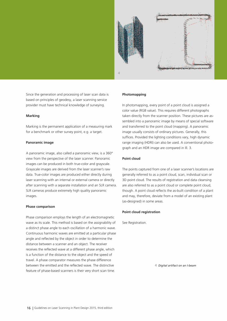
Digitalartifact
A digital artifact is produced by multiple reflections during the
digitization of a surface measurement point. It is not possible
to remove such really nonexistent points fully automatically
during data cleansing.
Dumbsolidmodel
A 3D model derived from a point cloud, i.e. the as-built condi-
tion, is called a dumb solid model. It does not contain any
intelligent data, e.g. temperature and pressure data or related
piping. Dumb solids can be modeled with different levels
of detail, beginning with the simple representation of areas
as envelopes (blocks) and ranging to fully detailed models.
Combinations of different levels of detail are quite common.
A dumb solid model can be used, for instance, for automatic
collision analysis and for presentation purposes. (Ill. 6)
E57standard
The E57 data format is a compact, vendor-neutral format for
the storage of point clouds, images and metadata. The data
format is specified by ASTM and is documented in the ASTM
standard E2807.
Georeferencing
Georeferencing is the transformation of a point cloud into a
local (facility or plant) coordinate system or a global coordinate
system.
HDRimage
See Photomapping.
2 Benchmark, Photo: Robert Wetzold,
pixello.de
3 Comparison of a conventional photo
(left) with an HDR image (right)
32
Laser scanning
Laser scanning is a method of scanning that uses a laser scan-
ner to scan the surfaces of objects without contact. Millions of
points are scanned automatically and, thus, entire objects are
scanned precisely and in detail within a few minutes. The data
generated by a laser scanner are called a point cloud. Suitable
processing programs combine point clouds from individual
scanner locations in one complete point cloud. 360-degree,
phase-based and/or time-of-flight laser scanners are preferred
for plant design and construction.
Since laser scanning is a method of optical measurement, a
laser scanner can only scan points that are visible from its loca-
tion. This is why any registered point cloud will also have areas
that do not contain any data. Such areas are called data voids.
Laserscanningserviceprovider
A laser scanning service provider is the company that does
the laser scanning. It is responsible for data capture, cleansing
and registration and, optionally, for modeling or analyses. The
laser scanning service provider is additionally responsible for
the compilation and delivery of the results as well as for the
quality and the completeness of the results of laser scanning
within the scope of the contracted service.
16 | Guidelines on Laser Scanning in Plant Design 2015, third edition
L a s e r s c a n n I n g I n d e r a n L a g e n p L a n u n g u n d I m a n L a g e n b a u
Since the generation and processing of laser scan data is
based on principles of geodesy, a laser scanning service
provider must have technical knowledge of surveying.
Marking
Marking is the permanent application of a measuring mark
for a benchmark or other survey point, e.g. a target.
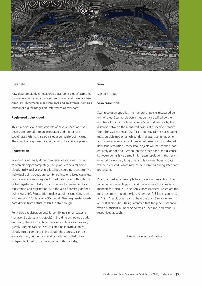
Panoramicimage
A panoramic image, also called a panoramic view, is a 360°
view from the perspective of the laser scanner. Panoramic
images can be produced in both true-color and grayscale.
Grayscale images are derived from the laser scanner’s raw
data. True-color images are produced either directly during
laser scanning with an internal or external camera or directly
after scanning with a separate installation and an SLR camera.
SLR cameras produce extremely high quality panoramic
images.
Phasecomparison
Phase comparison employs the length of an electromagnetic
wave as its scale. This method is based on the assignability of
a distinct phase angle to each oscillation of a harmonic wave.
Continuous harmonic waves are emitted at a particular phase
angle and reflected by the object in order to determine the
distance between a scanner and an object. The receiver
receives the reflected wave at a different phase angle, which
is a function of the distance to the object and the speed of
travel. A phase comparator measures the phase difference
between the emitted and the reflected wave. The distinctive
feature of phase-based scanners is their very short scan time.
Photomapping
In photomapping, every point of a point cloud is assigned a
color value (RGB value). This requires different photographs
taken directly from the scanner position. These pictures are as-
sembled into a panoramic image by means of special software
and transferred to the point cloud (mapping). A panoramic
image usually consists of ordinary pictures. Generally, this
suffices. Provided the lighting conditions vary, high dynamic
range imaging (HDRI) can also be used. A conventional photo-
graph and an HDR image are compared in Ill. 3.
Pointcloud
The points captured from one of a laser scanner’s locations are
generally referred to as a point cloud, scan, individual scan or
3D point cloud. The results of registration and data cleansing
are also referred to as a point cloud or complete point cloud,
though. A point cloud reflects the as-built condition of a plant
and may, therefore, deviate from a model of an existing plant
(as-designed) in some areas.
Pointcloudregistration
See Registration.
4
4 Digital artifact on an I-beam
Guidelines on Laser Scanning in Plant Design 2015, third edition | 17
L a s e r s c a n n I n g I n d e r a n L a g e n p L a n u n g u n d I m a n L a g e n b a u
Rawdata
Raw data are digitized measured data (point clouds) captured
by laser scanning, which are not registered and have not been
cleansed. Tachymeter measurements and an external camera’s
individual digital images are referred to as raw data.
Registeredpointcloud
This is a point cloud that consists of several scans and has
been transformed into an integrated and higher-level
coordinate system. It is also called a complete point cloud.
The coordinate system may be global or local (i.e. a plant).
registration
Scanning is normally done from several locations in order
to scan an object completely. This produces several point
clouds (individual scans) in a localized coordinate system. The
individual point clouds are combined into one large complete
point cloud in one integrated coordinate system. This step is
called registration. A distinction is made between point cloud
registration and registration with the aid of precisely defined
points (targets). Registration makes a point cloud congruent
with existing 2D plans or a 3D model. Planning (as-designed)
data differs from actual (as-built) data, though.
Point cloud registration entails identifying similar patterns
(surface structures and objects) in the different point clouds
and using these to combine the scans. Tolerances may vary
greatly. Targets can be used to combine individual point
clouds into a complete point cloud. The accuracy can be
easily defined, verified and additionally controlled by an
independent method of measurement (tachymetry).
scan
See point cloud.
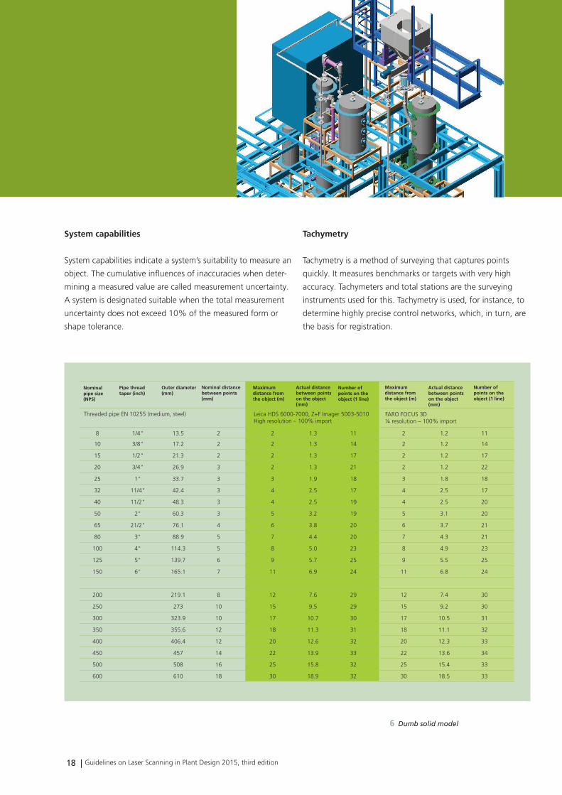
Scanresolution
Scan resolution specifies the number of points measured per
unit of area. Scan resolution is frequently specified by the
number of points in a laser scanner’s field of view or by the
distance between the measured points at a specific distance
from the laser scanner. A sufficient density of measured points
must be obtained on an object during laser scanning. When,
for instance, a very large distance between points is selected
(low scan resolution), then small objects will be scanned inad-
equately or not at all. When, on the other hand, the distance
between points is very small (high scan resolution), then scan-
ning will take a very long time and large quantities of data
will be produced, which may cause problems during later data
processing.
Piping is used as an example to explain scan resolution. The
table below presents piping and the scan resolution recom-
mended for Leica, Z+F and FARO laser scanners, which are the
most common in plant design. A Leica or Z+F laser scanner set
to “high” resolution may not be more than 8 m away from
a DN 100 pipe (4”). This guarantees that the pipe is scanned
with a sufficient number of points (23 per line) and, thus, is
recognized as such.
5 Grayscale panoramic image
5
18 | Guidelines on Laser Scanning in Plant Design 2015, third edition
L a s e r s c a n n I n g I n d e r a n L a g e n p L a n u n g u n d I m a n L a g e n b a u
Nominalpipe size(NPS)
Pipe threadtaper (inch)
Outer diameter(mm)
Nominal distancebetween points
)(mm
Maximumdistance fromthe object (m)
Actual distancebetween pointson the object(mm)
Number ofpoints on theobject (1 line)
Maximumdistance fromthe object (m)
Actual distancebetween pointson the object(mm)
Number ofpoints on theobject (1 line)
Threaded pipe EN 10255 (medium, steel) Leica HDS 6000-7000, Z+F Imager 5003-5010High resolution – 100% import
FARO FOCUS 3D¼ resolution – 100% import
.
.
.
.
.
.
.
.
.
.
.
.
.
.
.
.
.
.
.
.
.
.
.
.
.
.
.
.
.
.
.
.
.
.
.
.
.
.
.
.
.
.
.
.
.
.
.
.
.
.
.
.
.
.
.
.
.
.
.
Systemcapabilities
System capabilities indicate a system’s suitability to measure an
object. The cumulative influences of inaccuracies when deter-
mining a measured value are called measurement uncertainty.
A system is designated suitable when the total measurement
uncertainty does not exceed 10% of the measured form or
shape tolerance.
Tachymetry
Tachymetry is a method of surveying that captures points
quickly. It measures benchmarks or targets with very high
accuracy. Tachymeters and total stations are the surveying
instruments used for this. Tachymetry is used, for instance, to
determine highly precise control networks, which, in turn, are
the basis for registration.
6
6 Dumb solid model
Guidelines on Laser Scanning in Plant Design 2015, third edition | 19
L a s e r s c a n n I n g I n d e r a n L a g e n p L a n u n g u n d I m a n L a g e n b a u
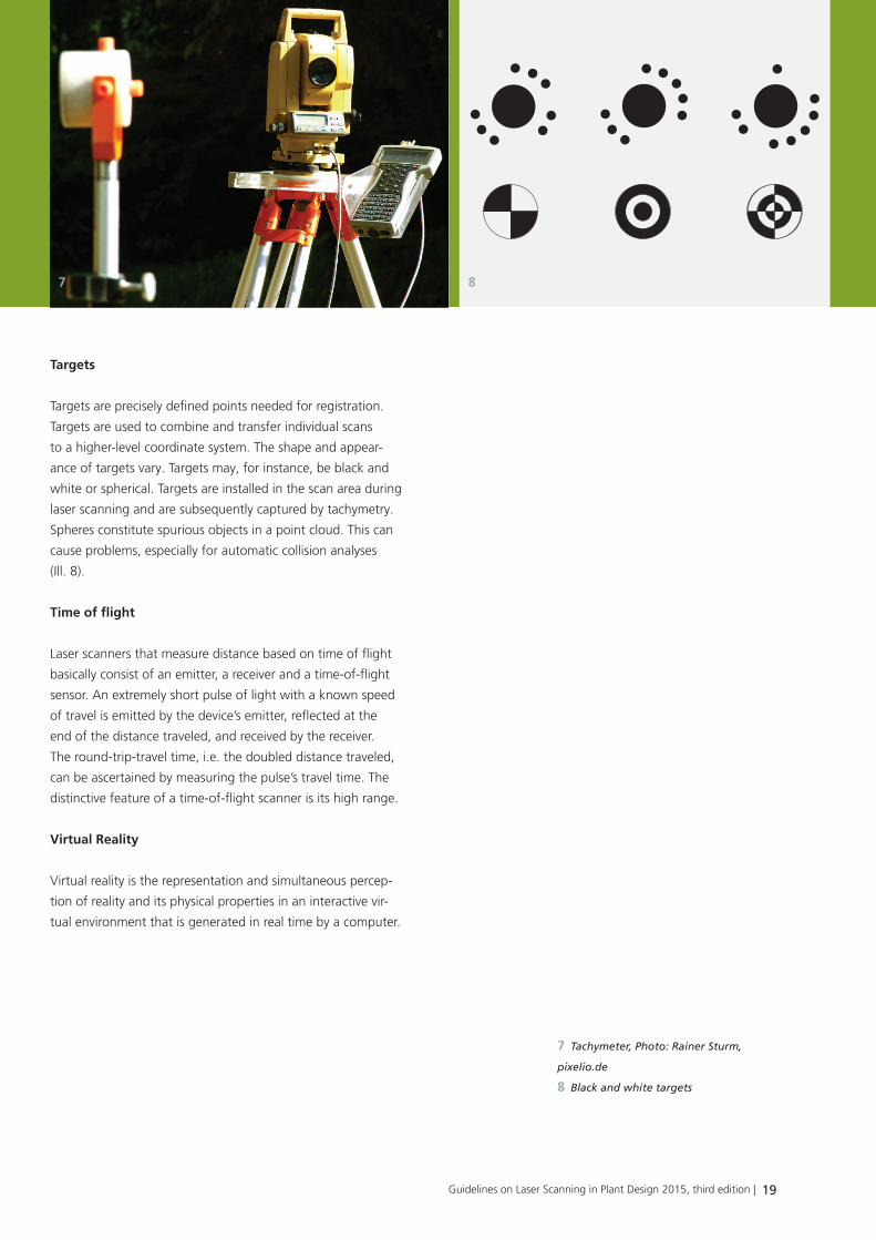
targets
Targets are precisely defined points needed for registration.
Targets are used to combine and transfer individual scans
to a higher-level coordinate system. The shape and appear-
ance of targets vary. Targets may, for instance, be black and
white or spherical. Targets are installed in the scan area during
laser scanning and are subsequently captured by tachymetry.
Spheres constitute spurious objects in a point cloud. This can
cause problems, especially for automatic collision analyses
(Ill. 8).
Timeofflight
Laser scanners that measure distance based on time of flight
basically consist of an emitter, a receiver and a time-of-flight
sensor. An extremely short pulse of light with a known speed
of travel is emitted by the device’s emitter, reflected at the
end of the distance traveled, and received by the receiver.
The round-trip-travel time, i.e. the doubled distance traveled,
can be ascertained by measuring the pulse’s travel time. The
distinctive feature of a time-of-flight scanner is its high range.
VirtualReality
Virtual reality is the representation and simultaneous percep-
tion of reality and its physical properties in an interactive vir-
tual environment that is generated in real time by a computer.
8
7 Tachymeter, Photo: Rainer Sturm,
pixelio.de
8 Black and white targets
7
20 | Guidelines on Laser Scanning in Plant Design 2015, third edition
Acknowledgements
We are grateful for the collaboration that led to the compila-
tion of these Guidelines on Laser Scanning in Plant Design.
We are particularly indebted to the exceptional expertise and
dedication of the following members of the Industry Working
Group for the successful compilation of these guidelines.
The following individuals were instrumental in the compilation
of these guidelines:
Mario Schedler
Dow Olefinverbund GmbH,
Leandros G. Zeppos
viin GmbH
Volker Werner
BKR Ingenieurbüro GmbH
Dr. Dirk Berndt
Fraunhofer Institute for Factory Operation
and Automation IFF
The following members of the Industry Working Group also
contributed their experience to the development of the
content of the technical specifications and requirements speci-
fication as well as recommendations for action. We
are particularly grateful to them, too.
Klaus Bach
Tebodin Peters Engineering GmbH
Bernd Bodeit
Tebodin Peters Engineering GmbH
Günter Eiermann
Weber Engineering GmbH & Co. KG
Harald Jedamski
ÖbVI Petersen GmbH
Steffen Mitzschke
AADIPLAN GmbH
Pascal Morovic
Tebodin Peters Engineering GmbH
Rene Münch
Wacker Chemie AG
Stephan Och
TPI Vermessungsgesellschaft mbH
Michael Rutz
BASF SE
Ulrich Schäfers
3D LASER SYSTEME GMBH
Tobias Weber
scantec3D GmbH
Axel Franke
BASF SE
Joachim Borgwart
BASF SE
Petra Urso
BASF SE
We would like to thank Prof. Heinz Runne from the Depart-
ment of Surveying and Geoinformation at Anhalt University of
Applied Sciences, for his professional suggestions and advice.

Guidelines on Laser Scanning in Plant Design 2015, third edition | 21
L a s e r s c a n n I n g I n d e r a n L a g e n p L a n u n g u n d I m a n L a g e n b a uL a s e r s c a n n I n g I n d e r a n L a g e n p L a n u n g u n d I m a n L a g e n b a uI m p r e s s u m
EditorialNotes
Laser Scanning Guidelines for Plant and Industry
Preparation and Execution of Laser Scanning Projects for Industrial Plant
Design and Documentation
Fraunhofer Institute for Factory Operation and Automation IFF
Publisher:
Prof. Michael Schenk
Sandtorstrasse 22 | 39106 Magdeburg | Germany
Phone +49 391 4090-0 | Fax +49 391 4090-596
http://www.iff.fraunhofer.de
Cover design: Bettina Rohrschneider
Editorial staff: Sabine Szyler, Andrea Urbansky, Virtual Interactive Training,
Fraunhofer IFF
Title picture: Point cloud overlaid with a 3D plant design model, Dow
Benelux B.V. (Marc de Bruyne)
Unless otherwise indicated, all photographs, pictures and graphics are
property of the Fraunhofer IFF.
urn:nbn:de:0011-n-4087491
All rights reserved.
No part of this publication may be translated, reproduced, stored in a
retrieval system, or transmitted in any form or by any means, electronic,
mechanical, photocopying, recording or otherwise, without the written
permission of the publisher. Many of the designations used by manufac-
turers and sellers to distinguish their products are claimed as trademarks
the quotation of those designations in whatever way does not imply the
conclusion that the use of those designations is legal without the consent
of the owner of the trademark.
© 03/2015 Fraunhofer Institute for Factory Operation and Automation IFF

Guidelines on Laser Scanning in Plant Design 2015, third edition | 22Guidelines on Laser Scanning in Plant Design 2015 | 22
L a s e r s c a n n I n g I n d e r a n L a g e n p L a n u n g u n d I m a n L a g e n b a u
laser scanninG and Virtual reality in Plant desiGn
The Laser Scanning and Virtual Reality in Plant Design Industry Working Group aims to use advanced 3D systems such as virtual and
augmented reality cost effectively throughout the entire life cycle of industrial plants. Plant engineering companies, plant operators,
hardware and software system developers and manufacturers, AR and VR system vendors, laser scanning service providers and as-built
documentation service providers collaborate closely in the Industry Working Group.
www.iff.fraunhofer.de