GUIDELINES ON FLOOD DISASTER MITIGATION FOR HIGHWAY …
122
IRC:SP:113-2018 INDIAN ROADS CONGRESS 2018 GUIDELINES ON FLOOD DISASTER MITIGATION FOR HIGHWAY ENGINEERS
Transcript of GUIDELINES ON FLOOD DISASTER MITIGATION FOR HIGHWAY …
IRC:SP:113-2018
INDIAN ROADS CONGRESS
2018
GUIDELINES
ON
FLOOD DISASTER MITIGATION
FOR HIGHWAY ENGINEERS
(The Official amendments to this document would be published bythe IRC in its periodical, ‘Indian Highways’ which shall be
considered as effective and as part of the Code/Guidelines/Manual,etc. from the date specified therein)
GUIDELINEs ON
FLOOD DIsAsTER MITIGATION FOR HIGHWAY ENGINEERs
Published by:
INDIAN ROADs CONGREssKama Koti Marg,
Sector-6, R.K. Puram, New Delhi-110 022
MAY, 2018
Price : ` 800/- (Plus Packing & Postage)

IRC:SP:113-2018
First Published : May, 2018
(All Rights Reserved. No part of this publication shall be reproduced, translated or transmitted in any form or by any means without the
permission of the Indian Roads Congress)
Printed by India Offset Press, Delhi-110 064 500 Copies

IRC:SP:113-2018
CONTENTs
s. No. Description Page No.
PERsONNEL OF THE GENERAL sPECIFICATIONs AND sTANDARDs COMMITTEE (Gss)
i-ii
INTRODUCTION 1
PROLOGUE 2
CHAPTER 1 : GENERAL1.1 The Indian Flood Hazard Scenario 10
1.2 Classification of Flood Prone Areas 11
1.3 Types of Floods 11
1.4 Sources of Flooding 12
1.5 The Flood Inflicted Damages on Roads 13
1.6 Floods as a Competent of Multiple Hazards 14
CHAPTER 2 : FLOOD HAZARD, VULNERABILITY AND RIsK AssEssMENT2.1 Flood Hazard and its Zonation 15
2.2 Infrastructure Mapping for Identification of Elements at Risk 15
2.3 Vulnerability of Elements at Risk 16
2.4 Flood Risk Assessment (FRA) 16
CHAPTER 3 : FLOOD sTUDIEs3.1 Topographical Characteristics 19
3.2 Hydrological Characteristics 19
3.3 River Characteristics 19
3.4 Road Development in Flood Plains 19
3.5 Road Development in Hilly Areas 20
3.6 Road Development in Coastal Areas 21
3.7 Damage Mapping 22
CHAPTER 4 : FLOOD MANAGEMENT WORKs 4.1 Introduction 23
4.2 Pre Flood Measures 24
4.3 Emergency Flood Protection Measures 40
4.4 Post Flood Measures for Safety and Control 42
4.5 Strengthening of Road Infrastructure in the Holistic Context 43
4.6 Measures for Protection against Floods 45
IRC:SP:113-2018
CHAPTER 5 : FLOOD CONTROL DEsIGN GUIDELINEs AND sTRUCTURAL METHODs5.1 Introduction 47
5.2 Design of Flood Embankments / Levees/Dikes / Road Embankments 47
5.3 Alignment, Function and Design of Groynes 50
5.4 Guide Bunds 52
5.5 Gabion Revetments 57
5.6 General Guidelines for Spur Design and Construction 58
5.7 General Guidelines for Porcupines 59
CHAPTER 6 : TECHNICAL sPECIFICATIONs 6.1 Specifications for Stones used in Pitching/Riprap 60
6.2 Stone Masonry 61
6.3 PCC/RCC Walls 61
6.4 Apron 61
6.5 Specifications of Geotextile Materials used for Anti Erosion, River Training and Bank Protection Works
63
6.6 Specifications for Geotextile Bags 63
6.7 Specifications of Geotextile Tubes 68
6.8 Specifications for Geocomposite Multi Cellular Structure 69
6.9 Specifications for Mechanically Woven Double Twisted Hexagonal Shaped Wire Mesh Gabions, Revet Mattresses and Cylindrical Gabions of Required Sizes, Galvanized + PVC Coated, Mechanically Edged / Selvedge
70
CHAPTER 7 : INsTALLATION AND CONsTRUCTION7.1 Introduction 78
7.2 Bank Protection Works/Slope Covering Works 78
7.3 Installation of Geotextile Bags used for Coastal and Riverine Structures 81
7.4 Installation of Geotextile Tubes used for Coastal and Riverine Structures 82
7.5 Installation and Preparation of Cylindrical Gabion Containment System 82
CHAPTER 8 : MAINTAINANCE AND MONITORING OF FLOOD MITIGATION sYsTEM 8.1 General 84
8.2 Inspection of Flood Embankments 84
8.3 Inspection during High Water Events 85
8.4 Post Flood Inspections and Evaluations 85
8.5 Dike Maintenance / Repair 86
8.6 Bank Protection Maintenance and Repair 86
8.7 Flood Box Maintenance 87

IRC:SP:113-2018
CHAPTER 9 : CONCLUsIONs, RECOMMENDATIONs AND THE WAY FORWARD9.1 Policy Framework 88
9.2 Recommendations 88
9.3 Planning, Design and Construction 89
9.4 Use of Smart Construction Materials 91
9.5 Mitigation and Management 92
9.6 Flood Protection Works 93
9.7 Standardization 93
9.8 Environment Friendly Solutions 94
9.9 Damage Assessment 94
9.10 Financial Provisions 95
CAsE sTUDIEs 96
REFERENCEs 102
BIBLIOGRAPHY 103
ANNEXURE-I 104
ANNEXURE-II 106
IRC:SP:113-2018
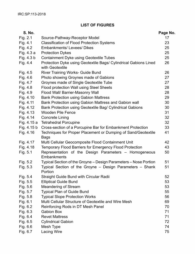
LIsT OF FIGUREs
s. No. Page No.Fig. 2.1 Source-Pathway-Receptor Model 17Fig. 4.1 Classification of Flood Protection Systems 23Fig. 4.2 Embankments/ Levees/ Dikes 25Fig. 4.3 a Protection Dykes 25Fig. 4.3 b Containment Dyke using Geotextile Tubes 25Fig. 4.4 Protection Dyke using Geotextile Bags/ Cylindrical Gabions Lined
with Geotextile26
Fig. 4.5 River Training Works- Guide Bund 26Fig. 4.6 Photo showing Groynes made of Gabions 27Fig. 4.7 Groynes made of Single Geotextile Tube 27Fig. 4.8 Flood protection Wall using Steel Sheets 28Fig. 4.9 Flood Wall/ Barrier-Masonry Wall 28Fig. 4.10 Bank Protection using Gabion Mattress 29Fig. 4.11 Bank Protection using Gabion Mattress and Gabion wall 30Fig. 4.12 Bank Protection using Geotextile Bag/ Cylindrical Gabions 30Fig. 4.13 Wooden Pile Fence 31Fig. 4.14 Concrete Lining 32Fig. 4.15 a Tetrahedral Porcupine 32Fig. 4.15 b Cross-section of a Porcupine Bar for Embankment Protection 33Fig. 4.16 Techniques for Proper Placement or Dumping of Sand/Geotextile
Bags41
Fig. 4.17 Multi Cellular Geocomposite Flood Containment Unit 42Fig. 4.18 Temporary Flood Barriers for Emergency Flood Protection 43Fig. 5.1 Representation of the Design Parameters – Homogeneous
Embankments50
Fig. 5.2 Typical Section of the Groyne – Design Parameters – Nose Portion 51Fig. 5.3 Typical Section of the Groyne – Design Parameters – Shank
Portion51
Fig. 5.4 Straight Guide Bund with Circular Radii 52Fig. 5.5 Elliptical Guide Bund 53Fig. 5.6 Meandering of Stream 53Fig. 5.7 Typical Plan of Guide Bund 55Fig. 5.8 Typical Slope Protection Works 56Fig. 6.1 Multi Cellular Structure of Geotextile and Wire Mesh 69Fig. 6.2 Reinforcing Rods in DT Mesh Panel 70Fig. 6.3 Gabion Box 71Fig. 6.4 Revet Mattress 71Fig. 6.5 Cylindrical Gabion 72Fig. 6.6 Mesh Type 74Fig. 6.7 Lacing Wire 75
IRC:SP:113-2018
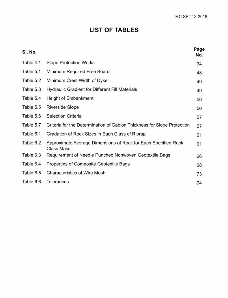
LIsT OF TABLEs
sl. No. Page No.
Table 4.1 Slope Protection Works 34Table 5.1 Minimum Required Free Board 48Table 5.2 Minimum Crest Width of Dyke 49Table 5.3 Hydraulic Gradient for Different Fill Materials 49Table 5.4 Height of Embankment 50Table 5.5 Riverside Slope 50Table 5.6 Selection Criteria 57Table 5.7 Criteria for the Determination of Gabion Thickness for Slope Protection 57Table 6.1 Gradation of Rock Sizes in Each Class of Riprap 61Table 6.2 Approximate Average Dimensions of Rock for Each Specified Rock
Class Mass61
Table 6.3 Requirement of Needle Punched Nonwoven Geotextile Bags 66Table 6.4 Properties of Composite Geotextile Bags 68Table 6.5 Characteristics of Wire Mesh 73Table 6.6 Tolerances 74

IRC:SP:113-2018
IRC:SP:113-2018
i
PERsONNEL OF THE GENERAL sPECIFICATIONs AND sTANDARDs COMMITTEE (Gss)
(As on 24th October, 2017)
1 Kumar, Manoj(Convenor)
Director General(RD) & Special Secretary to the Govt. of India, Ministry of Road Transport & Highways, New Delhi
2 Singh, B.N.(Co-Convenor)
Additional Director General, Ministry of Road Transport & Highways, New Delhi
3 Verma, Dr. S.K. (Member Secretary)
Chief Engineer SR&T(R), Ministry of Road Transport & Highways, New Delhi
Members
4 Basu, Kaushik Chief Engineer, Ministry of Road Transport & Highways
5 Bhardwaj, R.S. Senior Principal Scientist, Central Road Research Institute, New Delhi
6 Chacko, Dr. K.M. Director, Shriram Institute of Industral Research, Delhi
7 Eligar, J.H. Superintending Engineer, Ministry of Road Transport & Highways
8 Gupta, D.P. DG(RD) & AS (Retd), Ministry of Road Transport & Highways, New Delhi
9 Jain, Prof (Dr) S.S. Professor, IIT Roorkee
10 Jhamb, S.B. Addl. Director General(Retd.), Central Public Works Department, New Delhi
11 Joshi, L.K. Secretary(Retd.), Ministry of Road Transport & Highways, New Delhi
12 Lal, Bhure Chairman, Environment Pollution (Prevention & Control) Authority, Delhi
13 Mathur, Dr. Ajay Director General, The Energy & Resource Institute, New Delhi
14 Narain, Sunita Director General, Centre for Science & Environment, New Delhi
15 Goel, O.P. Director General(Retd), Central Public Works Department, New Delhi
16 Pandey, I.K. Chief Engineer, Ministry of Road Transport & Highways, New Delhi
17 Parrikar,G.M. Naik Superintending Engineer, PWD Goa
18 Pateriya, Dr. I.K. Director(Technical), National Rural Road Development Agency, New Delhi
19 Puri, S.K. DG(RD) & SS (Retd), Ministry of Road Transport & Highways, New Delhi
20 Rajoria, K.B. Engineer-in-Chief(Retd.), Delhi PWD, New Delhi
21 Raju, Dr.G.V.S. Engineer-in-Chief(Retd.), R& B Deptt., Hyderabad
IRC:SP:113-2018
ii
22 Rajvanshi, Ms. Asha Head, EIA Wild Life Institute, Dehradun
23 The Director (Reddy, D.N.)
Engineering Staff College of Engineering, Hyderabad
24 The CEO & PD (Sahay,Vishvajit)
National Automotive Testing and R&D Infrastructure Project, New Delhi
25 Sarangi, D Chief General Manager, National Highways Authority of India
26 Sharma, D. C. Principal Scientist, Central Road Research Institute, New Delhi
27 Sharma, M. P. Chief Engineer, Ministry of Road Transport & Highways, New Delhi
28 Sharma, R. S. Managing Director, M/s STP Ltd New Delhi
29 Sharma, V. K. Chief General Manager (LA), National Highways Authority of India, New Delhi
30 Sinha, A.V. DG (RD) & SS (Retd.), Ministry of Road Transport & Highways, New Delhi
31 Sinha, B.N. Chief Engineer (Retd.), Central Public Works Department, New Delhi
32 Tawade, D.O. Member(Technical), National Highways Authority of India, New Delhi
33 The Director General, (Mathur, Vishnu)
Society of Indian Automobile Manufacturers, New Delhi
34 The Director (Urdhwareshe, Mrs. Rashmi)
Automotive Research Association of India, Pune
35 Vasantha, Dr. C. Superintending Engineer, PWD Hyderabad
36 Verma, S K Advisor, Engineering Staff College of India, Hyderabad
37 Verma, Maj V.C. Director, M/s Oriental Structures Engineers Pvt. Ltd., New Delhi
38 Vyas, Neha Senior Environment Specialist, World Bank, New Delhi
Corresponding Members1 Momin, C.W. Chief Engineer, PWD Meghalaya
2 Parsekar, U P Principal Chief Engineer, PWD Goa
3 Sachdev,V.K. Chief Engineer (Retd), Ministry of Road Transport & Highways, New Delhi
4 Temjen, R. Temsu Addl. Chief Engineer, PWD Nagaland
5 Vanlaltluanga, R. Engineer-in-Chief, PWD Mizoram
Ex-Officio Members
1. President, IRC (Pradhan, N.K.) Engineer-in-Chief cum Secretary to the Govt. of Odisha, Bhubaneshwar
2. Director General (RD) & Spl. Secretary to the Govt. of India
(Kumar, Manoj) Ministry of Road Transport and Highways, New Delhi
3. Secretary General (Nirmal, S.K.) Indian Roads Congress, New Delhi
IRC:SP:113-2018
1
GUIDELINEs ON FLOOD DIsAsTER MITIGATION FOR HIGHWAY ENGINEERs
INTRODUCTION
The scope of the Guidelines on Flood Disaster Mitigation for Highway Engineers is limited to planning, design, construction and maintenance of roads and related infrastructure works in flood prone areas. It provides a general understanding of design-led approach to flood disaster mitigation with understanding of the associated hazards, vulnerabilities and risks. Pre and post disaster-responses and emergency works as related to the construction and maintenance of roads and road infrastructure in flood affected areas are covered.
The guidelines was under the consideration of Disaster Management Committee (G-6) since January 2015. The draft was discussed by G-6 Committee in a number of meetings. The G-6 Committee also constituted a Sub-Committee under the Chairmanship of Mrs. Minimol Korulla to draft / modify the chapters of Guidelines on Flood Disaster Mitigation for Highway Engineers for consideration of the G-6 Committee.
The Disaster Management Committee (list of personnel given below) in its meeting held on 20th June, 2017 finalized the Guidelines and recommended its submission to General Specifications and Standards Committee (GSS) for their consideration
Bhandari, Dr. R.K. …… ConvenorSinha, B.N. …… Co-ConvenorKumar, Dr. Kishor …… Member-Secretary
Members
Bhattacharjee, B.K. Pathak, M.M.Dash, B.C. Porwal, Dr. S.S.Dhodapkar, A.N. Sakamma, Mrs. S.Ghosh, Prof.(Dr.) Chandan Sanghi, A.K.Gupta, Kapil Sharma, ArunGupta, M.C. Sharma, D.D.Guru Vittal, U.K. Sodhi, M.S.Jaigopal, R.K. Subbarao, Dr. H.Jain, Dr. P.K. Velayutham, V.Joshi, Brig. Girish Verma, S.K.Naik, Gurunath M.
Corresponding MembersJohn, Dr. P.K. Karandikar, V.S.
Ex-Officio MembersPresident, IRC (Pradhan, N.K.)
DG(RD) & SS MORTH (Kumar, Manoj)
Secretary General, IRC (Nirmal, S.K.)
The draft guidelines were approved by the General Specifications and Standards Committee (GSS) in its meeting held on 24.10.2017 and subsequently by the Executive Committee in its meeting held on 02.11.2017 for placing before the Council. The document was approved by the IRC Council in its 213th meeting held on 03.11.2017 at Bengaluru (Karnataka) for publishing.
IRC:SP:113-2018
2
PROLOGUE
NEED FOR GUIDELINEs
There was a time when highway engineers were chiefly concerned with Storm Water Drainage (SWD) to ensure efficient drainage of roads and highways to deal with floods in the monsoon season. With the growing urbanization, land scarcity and population pressure, especially in the riverine, hilly and coastal areas, floods began to pose a major threat to the highways and the associated infrastructure in large parts of India. Gradually the threats of flood disasters have become so severe that integration of flood disaster mitigation with development planning is now a part of the stated policy of the Government of India. Flooding occurrences because of the factors such as urbanization, Extreme Weather Events, landslides, cyclones, storm surges and tsunamis are now receiving exceptional attention.
As our development plans get rolled out, we will have more and more of townships, roads, railway lines, tunnels, bridges, water resources projects including irrigation and hydroelectric projects and associated multi-purpose infrastructure in these very flood and flood-induced landslide prone areas. The challenges of planning and design of flood safe roads become even more daunting when earthquakes and landslides in turn add to the fury of floods on hill roads causing death and destruction, and hampering rescue and relief operations1.
National Disaster Management Guidelines-Management of Floods
India has the weight of history and richness of experience in dealing with flood disasters but flood disaster mitigation issues related to highway engineering have yet to receive a focused attention. Even in the National Disaster Management Guidelines on Management of Floods, published by National Disaster Management Authority (NDMA) in January 2008 after years of hard work involving 10 experts in the Core Group; 35 experts in the Extended Group and 162 other experts and stakeholders, the hardcore highway engineering related issues fell out of its scope. On the brighter side, the national vision articulated by the NDMA is “to minimize the vulnerability to floods and the consequent loss of lives, livelihood systems, property and damage to infrastructure and public utilities and build a safer India by developing holistic, pro-active, multi-disaster and technology driven strategy for Disaster Management”. The recommendations made in the Guidelines, also underscored the need for tightening of the techno-legal regime, enaction of legislation to curb unauthorized crossings and encroachments over drains, promotion of remote sensing techniques operated through artificial satellites, hazard mapping of areas affected by drainage congestion, recognition of embankment induced flooding and recourse to improved forecasting and early warning systems.
National Disaster Management Plan-Management of Floods
Upon release of the National Disaster Management Plan (NDMP) by the Prime Minister of India in June 2016, the national expectation is that “Every Ministry and every Department 1 The Kashmir earthquake of 2005 and the Sikkim earthquake of 18 September, 2011 triggered
landslides causing floods on the roads which hampered the rescue and relief operations.
IRC:SP:113-2018
3
should mainstream disaster preparedness and mitigation as a part of their development Plans”. Naturally, the flood disaster mitigation has become one of the major concerns in highway engineering particularly because the national plan does not emphasize that the flood disasters we face are more human-induced than natural. It is, therefore, essential that factors such as disorderly urbanization, non-engineered and ill-legal constructions, unchecked quarrying and mining, and human violence against nature all begin to matter in highway planning, design and construction.
Ministry of Urban Development is the nodal agency for urban floods and Ministry of Water Resources as the nodal ministry for riverine floods, but very little attention is currently being paid to floods affecting roads because of factors such as for example, Glacial Lake Outburst Floods which are of a major concern in design of high altitude roads.
In the real life situations, one type of hazard can trigger another type of hazard and many of our roads get affected by, for instance, flood induced landslides or landslide induced floods. Many of our roads are threatened by multiple hazards (floods included).It is our engineering obligation that all roads get certified as safe not only against floods, but against multiple hazards.
Findings of the Flooding related Task Forces and Committees
It is also the time that highway engineers benefit from the reports of flood-disasters driven Task Forces and Committees constituted by the Government of India from time to time. The NDMA Guidelines on Floods, inter alia, refers to a number of documents including the Flood Policy Statement of 1954; Revised Policy Statement of 1964 and National Water Policy of 1987; and the reports of the Ministers Committee of 1964; National Commission of 1999; Working Group on Flood Control Programme of X Five Year Plan of 2001, B.K. Mittal Committee of 2002 and the Rangachari and the C.B. Vashistha Committees of 2003.
Recently, in August 2016, the National Disaster Management Authority once again constituted an Expert Committee2 to visit the flood affected regions of Bihar in order to carry out assessment of flooding in many parts of the state due to the siltation problem. The Forum on Engineering Interventions for Disaster Mitigation of the Indian National Academy of Engineering, likewise, deliberated intensively on urban flood disaster mitigation in 2016 after massive floods of 2015 in Chennai. The scope of these studies did not cover the field of highway engineering.
IS 13739:1993- provides Guidelines for Estimation of Flood Damages. Inter alia, it suggests methods to quantify losses.
Flood Vulnerability of the vast expanse of the Indian Road Network
At its independence, India inherited a poor network of roads, most of which were single lane, until about 1988. At that time India was without Express ways. All it had was about a couple of hundred kilometers of 4-lane highways. The year 1989 turned out to be a game changer with
2 OM No. 8(7) / Flood (Bihar) 2016/NDMA dated 31st August, 2016
IRC:SP:113-2018
4
the establishment of NHAI on 15 June 1989 as an autonomous body by an Act of Parliament. Today, India’s road network is the second largest road network in the world which will soon approach 0.7 km of roads per square kilometer of land. Many of these roads pass through areas prone to cyclones, floods, landslides and earthquakes. Naturally, the flood-safety of our roads deserves the highest priority.
The Challenges facing the Indian Highway Engineers
There are several factors which makes India’s roads different from those of the rest of world. Our roads are an unholy mix of most modern, all season, 4-lane-highways on the one hand to the unpaved roads and narrow track roads on the other hand. Most of our roads in different geo-climatic settings are vulnerable to hazards of different types, including flood hazards. Although at the project formulation stage, the national plan directs us to integrate road planning and development with disaster management, yet in the current engineering practice that seldom happens. Also, once a highway project gets completed, the considerations of flood hazard mitigation get relegated to the back-burner. There are hardly any investments in prevention and mitigation of flood disasters which is why our roads and road infrastructure suffer hugely because of flood disasters.
Implications of Rapid Pace of Development
The flood hazard mitigation strategies are significantly influenced by the rapid pace of development. There are several factors which makes India’s roads different from those of the rest of world. Our roads are an unholy mix of most modern, all season, 4-lane-highways on the one hand to the unpaved roads and narrow track roads on the other hand. In different geo-climatic settings, they are vulnerable to hazards of different types, including flood hazards. In response, at the project formulation stage, we must integrate road planning and development with disaster management. Once the project gets completed, then also, considerations of road safety against multiple hazards must receive attention of the project authorities. Currently, there are hardly any investments in prevention and mitigation of flood disasters which is why our roads and road infrastructure suffer hugely and the recovery is painfully slow.
Flood Vulnerability of Roads in Urban Areas
If the present trends are any indicator, urban areas in India are rapidly expanding and the associated road network is becoming even more vulnerable to urban flooding. Since highway engineering planning, design and construction practices have not improved fast enough to match with the growing vulnerability of roads to urban floods, it is imperative that the present Acts related to Town planning, Industrial zone planning, Land reforms and Transportation corridors are expeditiously reviewed and amended. Preservation of water bodies, efficient disposal of urban wastes, total ban on encroachments, revamping of existing drainage systems, augmentation of surface and sub-surface drainage all need exception attention.
IRC:SP:113-2018
5
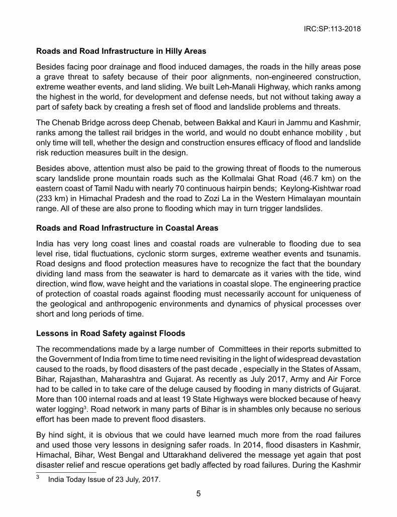
Roads and Road Infrastructure in Hilly Areas
Besides facing poor drainage and flood induced damages, the roads in the hilly areas pose a grave threat to safety because of their poor alignments, non-engineered construction, extreme weather events, and land sliding. We built Leh-Manali Highway, which ranks among the highest in the world, for development and defense needs, but not without taking away a part of safety back by creating a fresh set of flood and landslide problems and threats.
The Chenab Bridge across deep Chenab, between Bakkal and Kauri in Jammu and Kashmir, ranks among the tallest rail bridges in the world, and would no doubt enhance mobility , but only time will tell, whether the design and construction ensures efficacy of flood and landslide risk reduction measures built in the design.
Besides above, attention must also be paid to the growing threat of floods to the numerous scary landslide prone mountain roads such as the Kollmalai Ghat Road (46.7 km) on the eastern coast of Tamil Nadu with nearly 70 continuous hairpin bends; Keylong-Kishtwar road (233 km) in Himachal Pradesh and the road to Zozi La in the Western Himalayan mountain range. All of these are also prone to flooding which may in turn trigger landslides.
Roads and Road Infrastructure in Coastal Areas
India has very long coast lines and coastal roads are vulnerable to flooding due to sea level rise, tidal fluctuations, cyclonic storm surges, extreme weather events and tsunamis. Road designs and flood protection measures have to recognize the fact that the boundary dividing land mass from the seawater is hard to demarcate as it varies with the tide, wind direction, wind flow, wave height and the variations in coastal slope. The engineering practice of protection of coastal roads against flooding must necessarily account for uniqueness of the geological and anthropogenic environments and dynamics of physical processes over short and long periods of time.
Lessons in Road safety against Floods
The recommendations made by a large number of Committees in their reports submitted to the Government of India from time to time need revisiting in the light of widespread devastation caused to the roads, by flood disasters of the past decade , especially in the States of Assam, Bihar, Rajasthan, Maharashtra and Gujarat. As recently as July 2017, Army and Air Force had to be called in to take care of the deluge caused by flooding in many districts of Gujarat. More than 100 internal roads and at least 19 State Highways were blocked because of heavy water logging3. Road network in many parts of Bihar is in shambles only because no serious effort has been made to prevent flood disasters.
By hind sight, it is obvious that we could have learned much more from the road failures and used those very lessons in designing safer roads. In 2014, flood disasters in Kashmir, Himachal, Bihar, West Bengal and Uttarakhand delivered the message yet again that post disaster relief and rescue operations get badly affected by road failures. During the Kashmir 3 India Today Issue of 23 July, 2017.
IRC:SP:113-2018
6
floods of 2014, roads in many areas like Indira Nagar and Shiv Pura were submerged under several meters of water bringing the life to a grinding halt.
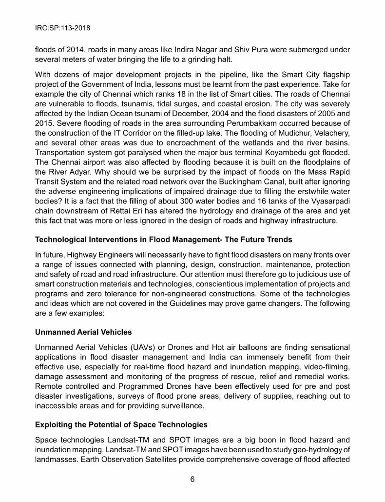
With dozens of major development projects in the pipeline, like the Smart City flagship project of the Government of India, lessons must be learnt from the past experience. Take for example the city of Chennai which ranks 18 in the list of Smart cities. The roads of Chennai are vulnerable to floods, tsunamis, tidal surges, and coastal erosion. The city was severely affected by the Indian Ocean tsunami of December, 2004 and the flood disasters of 2005 and 2015. Severe flooding of roads in the area surrounding Perumbakkam occurred because of the construction of the IT Corridor on the filled-up lake. The flooding of Mudichur, Velachery, and several other areas was due to encroachment of the wetlands and the river basins. Transportation system got paralysed when the major bus terminal Koyambedu got flooded. The Chennai airport was also affected by flooding because it is built on the floodplains of the River Adyar. Why should we be surprised by the impact of floods on the Mass Rapid Transit System and the related road network over the Buckingham Canal, built after ignoring the adverse engineering implications of impaired drainage due to filling the erstwhile water bodies? It is a fact that the filling of about 300 water bodies and 16 tanks of the Vyasarpadi chain downstream of Rettai Eri has altered the hydrology and drainage of the area and yet this fact that was more or less ignored in the design of roads and highway infrastructure.
Technological Interventions in Flood Management- The Future Trends
In future, Highway Engineers will necessarily have to fight flood disasters on many fronts over a range of issues connected with planning, design, construction, maintenance, protection and safety of road and road infrastructure. Our attention must therefore go to judicious use of smart construction materials and technologies, conscientious implementation of projects and programs and zero tolerance for non-engineered constructions. Some of the technologies and ideas which are not covered in the Guidelines may prove game changers. The following are a few examples:
Unmanned Aerial Vehicles
Unmanned Aerial Vehicles (UAVs) or Drones and Hot air balloons are finding sensational applications in flood disaster management and India can immensely benefit from their effective use, especially for real-time flood hazard and inundation mapping, video-filming, damage assessment and monitoring of the progress of rescue, relief and remedial works. Remote controlled and Programmed Drones have been effectively used for pre and post disaster investigations, surveys of flood prone areas, delivery of supplies, reaching out to inaccessible areas and for providing surveillance.
Exploiting the Potential of space Technologies
Space technologies Landsat-TM and SPOT images are a big boon in flood hazard and inundation mapping. Landsat-TM and SPOT images have been used to study geo-hydrology of landmasses. Earth Observation Satellites provide comprehensive coverage of flood affected
IRC:SP:113-2018
7
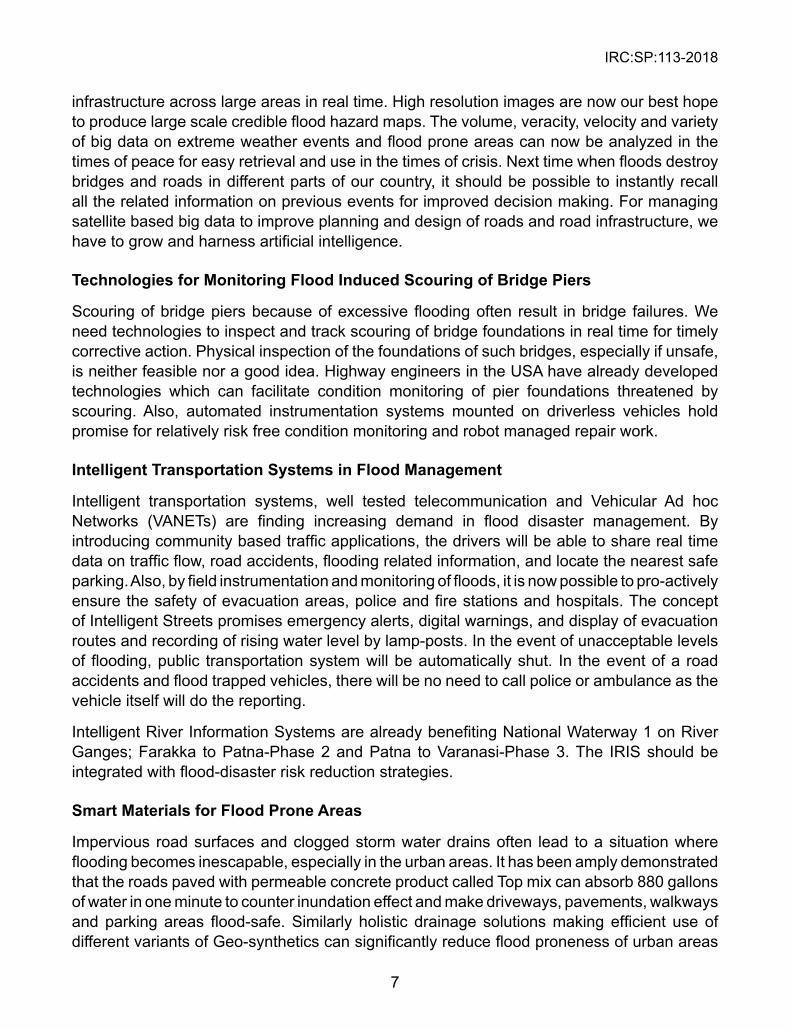
infrastructure across large areas in real time. High resolution images are now our best hope to produce large scale credible flood hazard maps. The volume, veracity, velocity and variety of big data on extreme weather events and flood prone areas can now be analyzed in the times of peace for easy retrieval and use in the times of crisis. Next time when floods destroy bridges and roads in different parts of our country, it should be possible to instantly recall all the related information on previous events for improved decision making. For managing satellite based big data to improve planning and design of roads and road infrastructure, we have to grow and harness artificial intelligence.
Technologies for Monitoring Flood Induced scouring of Bridge Piers
Scouring of bridge piers because of excessive flooding often result in bridge failures. We need technologies to inspect and track scouring of bridge foundations in real time for timely corrective action. Physical inspection of the foundations of such bridges, especially if unsafe, is neither feasible nor a good idea. Highway engineers in the USA have already developed technologies which can facilitate condition monitoring of pier foundations threatened by scouring. Also, automated instrumentation systems mounted on driverless vehicles hold promise for relatively risk free condition monitoring and robot managed repair work.
Intelligent Transportation systems in Flood Management
Intelligent transportation systems, well tested telecommunication and Vehicular Ad hoc Networks (VANETs) are finding increasing demand in flood disaster management. By introducing community based traffic applications, the drivers will be able to share real time data on traffic flow, road accidents, flooding related information, and locate the nearest safe parking. Also, by field instrumentation and monitoring of floods, it is now possible to pro-actively ensure the safety of evacuation areas, police and fire stations and hospitals. The concept of Intelligent Streets promises emergency alerts, digital warnings, and display of evacuation routes and recording of rising water level by lamp-posts. In the event of unacceptable levels of flooding, public transportation system will be automatically shut. In the event of a road accidents and flood trapped vehicles, there will be no need to call police or ambulance as the vehicle itself will do the reporting.
Intelligent River Information Systems are already benefiting National Waterway 1 on River Ganges; Farakka to Patna-Phase 2 and Patna to Varanasi-Phase 3. The IRIS should be integrated with flood-disaster risk reduction strategies.
smart Materials for Flood Prone Areas
Impervious road surfaces and clogged storm water drains often lead to a situation where flooding becomes inescapable, especially in the urban areas. It has been amply demonstrated that the roads paved with permeable concrete product called Top mix can absorb 880 gallons of water in one minute to counter inundation effect and make driveways, pavements, walkways and parking areas flood-safe. Similarly holistic drainage solutions making efficient use of different variants of Geo-synthetics can significantly reduce flood proneness of urban areas
IRC:SP:113-2018
8
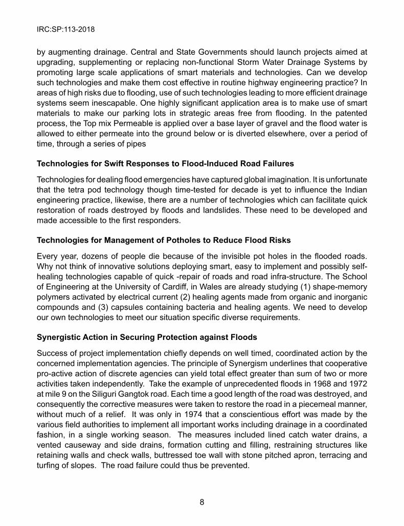
by augmenting drainage. Central and State Governments should launch projects aimed at upgrading, supplementing or replacing non-functional Storm Water Drainage Systems by promoting large scale applications of smart materials and technologies. Can we develop such technologies and make them cost effective in routine highway engineering practice? In areas of high risks due to flooding, use of such technologies leading to more efficient drainage systems seem inescapable. One highly significant application area is to make use of smart materials to make our parking lots in strategic areas free from flooding. In the patented process, the Top mix Permeable is applied over a base layer of gravel and the flood water is allowed to either permeate into the ground below or is diverted elsewhere, over a period of time, through a series of pipes
Technologies for swift Responses to Flood-Induced Road Failures
Technologies for dealing flood emergencies have captured global imagination. It is unfortunate that the tetra pod technology though time-tested for decade is yet to influence the Indian engineering practice, likewise, there are a number of technologies which can facilitate quick restoration of roads destroyed by floods and landslides. These need to be developed and made accessible to the first responders.
Technologies for Management of Potholes to Reduce Flood Risks
Every year, dozens of people die because of the invisible pot holes in the flooded roads. Why not think of innovative solutions deploying smart, easy to implement and possibly self-healing technologies capable of quick -repair of roads and road infra-structure. The School of Engineering at the University of Cardiff, in Wales are already studying (1) shape-memory polymers activated by electrical current (2) healing agents made from organic and inorganic compounds and (3) capsules containing bacteria and healing agents. We need to develop our own technologies to meet our situation specific diverse requirements.
synergistic Action in securing Protection against Floods
Success of project implementation chiefly depends on well timed, coordinated action by the concerned implementation agencies. The principle of Synergism underlines that cooperative pro-active action of discrete agencies can yield total effect greater than sum of two or more activities taken independently. Take the example of unprecedented floods in 1968 and 1972 at mile 9 on the Siliguri Gangtok road. Each time a good length of the road was destroyed, and consequently the corrective measures were taken to restore the road in a piecemeal manner, without much of a relief. It was only in 1974 that a conscientious effort was made by the various field authorities to implement all important works including drainage in a coordinated fashion, in a single working season. The measures included lined catch water drains, a vented causeway and side drains, formation cutting and filling, restraining structures like retaining walls and check walls, buttressed toe wall with stone pitched apron, terracing and turfing of slopes. The road failure could thus be prevented.

IRC:SP:113-2018
9
The Main Thrust of the Disaster Management Committee (G-6) of IRC
The scope of the flood disaster mitigation is huge and the associated challenges are daunting as stated above. The added challenges because of the ambitious plans and rapid rate of construction underscore the need to ensure that our roads are resilient against all types of hazards, including floods. Naturally, the scope of the agenda on disaster risk resilience before the highway engineers goes way beyond the scope of these Guidelines restricted to some aspects of flood disaster mitigation. Since the scope of coverage on the subject could be huge in the expanding world of knowledge, the document in your hands is to be regarded as the work in progress- the first step- in the long journey ahead.
In the light of the foregoing, the Disaster Management Committee (G-6) strongly recommends that IRC should take suo moto cognizance of the entire sweep of problems related to the flood vulnerability of roads and road-infrastructure outlined above and undertake projects and programmes with pro-active engagement of all the stakeholders.

IRC:SP:113-2018
10
CHAPTER 1
GENERAL
1.1 The Indian Flood Hazard scenario
India’s about 12% of the land area is estimated to be flood prone but the current trends leave one in no doubt that the figure needs upward revision. In 1998, the floods affected nearly 37% of India’s land area and the picture has not improved since. Of the nearly 40 million hectares prone to floods, on an annual average, 7.5 million hectares gets affected causing loss of human and animal lives, damaging agriculture crops, destroying houses, roads and public utilities, and costing thousands of crores to the Nation4.
There is hardly any part of India which is not flood prone and without history of catastrophic flood disasters. Of the India’s 62 major rivers, 18 are highly flood prone and drain an area of 150 Mha often flooding the roads on their banks. Roads along India’s 5700 km long coastline -made of 2700km of the east-coast bordering the Bay of Bengal and 3000 km of the west-coast bordering the Arabian sea - suffers annually from the damaging meteorological events such as tropical cyclones, storm surges, high winds, flooding and coastal erosion. The Bay of Bengal and the Arabian Sea together generate about 5-6 tropical cyclone annually, of which 2-3 could be quite severe. And these often throw the road network in to disarray, slowing down the pace of development. This is a matter of serious concern particularly because the construction of highways has already reached an all-time high of 6,029 km during FY 2015-16. The faster pace of road construction in flood prone areas is, therefore, a matter of newly emerging challenge.
The vital question to ask is how the highway engineering profession, which has so far not succeeded in reducing flood vulnerability of roads, can now do things differently to ensure that the ongoing road development, in itself, does not become a disaster? An intensive effort is required to counter uncontrolled urbanization, recurring flooding, extremely poor road drainage and dysfunctional storm water drainage systems. If we fail to counter flood disasters, not only the advantage of high speed corridors will be lost but traffic jams will hamper the rescue, evacuation and relief operations in the times of crisis.
It is not always easy to prevent flooding of a poorly designed and hurriedly completed road but a lot can be achieved to support the new road projects which are still on the drawing table .For instance NHAI plans to take-up 82 highway development projects to connect ports under the Bharatmala project. Of the 35000 km of roads to be developed across India at the cost of Rs 3 trillion, 21000 km will be economic corridors and 15000 km will be feeder routes. Moreover, the Ministry of Road Transport and Highways plans to build five more Greenfield expressways across the country, which are expected to reduce travel time with improved road safety. It is time to convince the nation that all the new road constructions will be free from the menace of flooding and other hazards.
4 NDMA Guidelines for Management of Floods, 2008
IRC:SP:113-2018
11
1.2 Classification of Flood Prone Areas
Flood prone areas of India can be broadly fall in (a) Ganga Basin (b) Brahmaputra and Barak Basin and (c) Central India and Deccan River Basins.
The Ganga Basin gets flooded by its northern tributaries mostly in the northern parts. The worst affected States of the Ganga basin are the States of West Bengal, Bihar and Uttar Pradesh, the eastern part of it is also affected by flood in rivers like Sarada, Rapti, Gandak and Ghaghra. Floods in river Yamuna affects the states of Haryana and Delhi; and tidal surges and insufficient river channels are some of the causes of flooding of rivers Mahanadi, Bhagirathi and Damodar in West Bengal.
The banks of rivers Brahmaputra and Barak Basins get frequently flooded due to the rapidly changing hydrology and altered landscape of the Brahmaputra and the Barak basins. These rivers and their tributaries flood the northeastern states like West Bengal, Assam and Sikkim. Jaldakha, Teesta and Torsa rivers in northern West Bengal and rivers in Manipur are also known to overflow their banks.
Central India and Deccan Rivers Basins are also greatly affected by floods. Rivers Mahanadi, Baitarni and Brahmani play havoc due to flooding in the state of Odisha. The delta region formed by these three rivers is highly vulnerable because it is thickly populated. Even some small rivers of Kerala and mud streams from the nearby hills add to the fury of floods. Cyclonic storms in the deltaic regions of Godavari, Mahanadi and Krishna floods the coastal regions of Andhra Pradesh, Odisha and Tamil Nadu occasionally. Narmada, Godavari, Tapti, Krishna and Mahanadi flood Southern and Central India due to heavy rainfall.
1.3 Types of Floods
Broadly speaking, the floods may be classified as :(a) riverine floods (b) urban area floods (c) flash floods, and (d) coastal floods.
Riverine Floods occurs when rivers overtops its banks while in spate due to a variety of reasons including heavy rainfall.
Urban Area Floods result from the interplay of a multitude of factors. Encroachment of water bodies, blocking and fouling of natural drainage, casual approach to solid waste disposal, heavy rainfall, poor drainage system and its neglect are some of the well-known causes. Urban areas along the river banks and coastal belts. Urban areas get flooded because of a multitude of factors. River floods, Coastal floods, Extreme Weather Events and Dam bursts in upstream regions are often the cause of urban flooding. Blocking of Drainage system due to silting, dumping of waste material at the inlets of drainage, encroachment over natural drainage and water bodies are known to aggravate urban flooding.
Flash floods are rapid occurring events which generally follow very high intensity short duration rainfalls, especially in poorly drained areas. This type of flooding give almost no notice as flooding usually begins within a few minutes or hours of the extreme weather events. The rapidly rising water can reach heights of 10 m or more and gains power to roll boulders, rip
IRC:SP:113-2018
12
trees from the ground, and destroy roads and bridges. The damages caused by flash floods can be more severe than the ordinary riverine floods because of the high speed with which the flooding occurs, loaded with the charge of debris. Channel velocities of 3 m/s, typically realized in flash floods, can move a rock weighing 40 kg.
Coastal flooding takes place when normally dry, low-lying lands get inundated by sea water. The extent of coastal flooding is a function of the elevation of inland flood waters penetration which is chiefly controlled by the topography of the coastal land exposed to flooding. The sea water can invade the land areas in different ways. Coastal flooding affects not only coastal areas but may extend along estuaries and coastal lakes and rivers some distance from the ocean. The flooding because of the cyclonic storm surges and tidal phenomenon is common. The leading edge of the incoming tide forms a wave (or waves) of water and the waves travel up a river or narrow bay against the direction of the river or bay’s current. In exceptional cases, an undersea earthquake can trigger a tsunami which usually carry the power to ravage the coast. The Indian Ocean tsunami of 24 January 2003 is an example of widespread devastation caused by a tsunami.
1.4 sources of Flooding
There are many major sources of flooding. Some of these are (a) tidal flooding (b) fluvial flooding (c) ground water flooding (d) pluvial flooding, and (e) flooding from sewers. In the hilly areas, roads are also affected by events such as bursting of glacial lakes and landslide dams.
Peak high tides and low pressure weather systems may combine to challenge and overtop the sea and river defense structures to cause tidal flooding of the sea coasts. The onset of flooding from the sea and tidal rivers is rapid and the extreme forces driving it pose significant danger to life and property.
Fluvial Flooding occurs in the floodplains of rivers when the capacity of water courses is exceeded as a result of rainfall or snow and ice melts within catchment areas further upstream. Blockages of water courses and flood channels or tide locking may also lead to ponding and rising water levels. River defenses may then be overtopped due to increased water levels, or may get breached by large objects of debris carried at high water velocities.
Low lying areas located over unconfined aquifers may periodically flood as ground water levels rise. This type of flooding is often seasonal, driven by monsoon rains, and therefore can be anticipated with good accuracy. It is often slow in its onset.
Pluvial Flooding: Surface water flooding is caused by rainwater run-off from urban and rural lands with low ground absorption. Increased pace of high density development in urban areas has given rise to land with a larger proportion of non-permeable surfaces, a problem often exacerbated by overloaded and outdated drainage infrastructure. These circumstances, combined with intense rainfall, can give rise to localized flooding. This sort of flooding often occurs outside of recognized floodplains. Further, since it is caused by quite localized weather conditions, it is very difficult to forecast. Its onset can also be very rapid, and the level of flooding very severe.
IRC:SP:113-2018
13
Flooding from Sewers: A sewerage system conveys sewage and surface water runoff using sewers. It includes drains, manholes, pumping stations, storm overflows, and screening chambers of the combined sewer or foul sewer. Flooding from sewers can occur where their capacity is exceeded due to large amounts of surface water run-off in a short time. Poor cleaning and maintenance can lead to blockages that can also cause local flooding. This type of flooding is hard to predict, has significant sanitary consequences for those affected, and can occur very rapidly.
1.5 The Flood Inflicted Damages on Roads
Events of the recent years bear testimony to the fact that every major flood disaster invariably affects roads and bridges.
The Bihar floods of 20175 affected 10 National Highways, 203 State Highways and in fact the entire road network in north Bihar. Six bridges also suffered extensive damages. The total estimated damages were to the tune of Rs 1000 crore. As anticipated, the maximum damages to roads were recorded in as many as 20 districts including Purnea, Katihar, Araria, Kishanganj, East Champaran and West Champaran. Submergence of roads and erosion of approach roads to bridges was wide spread. Submergence of parts of the 3300 km-long east-west corridor stretching from Porbandar in Gujarat to Silchar in Assam and damages to approach embankments on NH 31 became matters of grave concern and these would cost several hundred crores of rupees of repair, restoration and reconstruction. The repeat of such damages can be prevented by taking course to implementation of a well-designed package of mitigation measures, some of which are discussed in succeeding chapters.
Jammu and Kashmir floods of 20146 provides yet another example with great lessons in flood disaster mitigation. Unchecked urbanization, heavy monsoon rains and extremely poor drainage combined to burst the banks of rivers Jhelum, Chenab and Tawi, among others. The worst affected districts were Srinagar, Anantnag, Baramulla, Pulwama, Ganderbal, Kulgam, Budgam, Rajouri, Poonch and Reasi. Links of Kashmir Valley were disrupted and the 300 km- long National Highway was closed to vehicular traffic for days as a result of landslides and floods. As many as 60 major and minor roads were cut off and over 30 bridges got washed away, hampering the relief and rescue operations. Except for connectivity between Srinagar and North Kashmir’s Ganderbal district, all other districts of the valley including Anantnag, Pulwama, Kulgam, Shopian, Badgam, Baramulla and Bandipora were cut off.
Over the years, several expert Committees have studied the problems caused by floods and suggested various measures for flood disaster risk reduction to the Government. However, despite the various initiatives taken and interventions made over the last five decades, the flood disasters have only increased in frequency, spread and magnitude of damage and devastation, posing unprecedented challenge to the highway engineers. Besides the increasing levels of hazard, the vulnerability is also on the increase due to a multitude of
5 *Source: The Telegraphindia.com/Bihar-floods6 Source: Rapid Joint Needs Assessment Report-Phase-01, Jammu & Kashmir Floods 2014
IRC:SP:113-2018
14
factors such as higher degree of exposure to floods, uncontrolled urbanization and Extreme Weather Events.
1.6 Flood as a Component of Multiple Hazards
The flooding as hazard can occur in isolation or conjointly with other hazards. For example Glacial Lake Outburst Floods can trigger landslides which may in turn lead to flooding of the associated water streams. Similarly, when flooding in a river causes toe erosion of a slope, its instability may result in a landslide. Such massive landslides are known to block the river and form a landslide dam, bursting of which may trigger more landslides. The large boulders or debris which are carried by a river can damage roads and infrastructure along the river banks.
IRC:SP:113-2018
15
CHAPTER 2
FLOOD HAZARD, VULNERABILITY AND RIsK AssEssMENT
2.1 Flood Hazard and its Zonation
Hazard is defined as probability of occurrence of a hazardous event within a specified time frame in a given area of potentially damaging phenomena. The areas which have the greatest danger of flooding are usually the flood plains, the lower river terraces, the coastal plains, poorly drained hilly areas and unplanned, poorly drained urban areas. The zones of flooding and inundation are ranked in terms of their degree of severity after careful study and analysis of all the various causative factors and their interplay. The flooding depends in a big way on the geomorphology and hydro-geology of the area, river characteristics, rainfall and the catchment attributes defined in terms of size, shape, relative relief, topography, hydrogeology, drainage density, stream order, land uses. These factors form the basis of thematic maps which to be are prepared at an appropriate scale based on the weights assigned to the individual features according to their relative importance in flood occurrence. Different flood hazard zones get labeled as ‘high’, ‘moderate’ and ‘low’. The thematic layers are finally integrated using Auto Desk MAP and MapInfo GIS software to flood hazard zonation map of the study area. The detailed analysis flood hazard zonation is described in Annex II.
Modern techniques are assets for proper understanding, utilization and management of precious natural resources, especially water. Of the many efficient techniques for flood hazard zonation, the most significant is Geoinformatics comprising RS (Remote Sensing), GIS (Geographic Information System) and GPS (Global Positioning System).
Geographic Information system (GIS) is a computer-based system that provides the capabilities for input, data management (data storage and retrieval), manipulation and analysis, and output to handle geo-referenced data. It provides a broad range of tools for determining area affected by floods and for forecasting areas that are likely to be flooded due to high water level in a river. GIS is also being extensively used to assemble information from different maps, aerial photographs, satellite images and digital elevation models (DEM).
For determination of risk, it is important to know the elements at risk and their levels of exposure. By preparing an infrastructure map at the scale of the flood hazard map, the elements at risk can easily be identified on a GIS platform.
2.2 Infrastructure Mapping for Identification of Elements at Risk
For determination of risk, alongside flood hazard mapping, it is essential to carry out mapping of all the objects at risk to prepare the corresponding infrastructure map at the scale. The infrastructure map generally includes items such as human settlements, road infrastructure, heritage structures, public utilities, hospitals, school buildings, police and fire stations. Special attention must be paid to structures situated within a flood plain, mud or masonry buildings with water-soluble mortar, buildings with shallow foundations or weak resistance to lateral
IRC:SP:113-2018
16
loads or impact, roads and bridges in strategic areas, basements or underground buildings; public utilities in congested areas, industries in low-lying areas, food stocks , cultural artifacts, confined livestock , coastal infrastructure. The study of flood hazard and the corresponding infrastructure map on a GIS platform will lead to identification of elements at risk.
2.3 Vulnerability of Elements at Risk
For risk assessment, it is not enough to have the flood hazard and Infrastructure maps. By these two, we can only identify what all is at risk. For quantification of risk, we must assess the degree of vulnerability of the all the elements at risk. The vulnerability of an element at risk could vary from zero to one. For instance, a well-engineered road with functionally efficient drainage system will have zero vulnerability to flooding. The vulnerability of the same road, if badly built and with poor drainage may be 100%. In other words, vulnerability depends on level of exposure, susceptibility and degree of preparedness.
There are different types of vulnerability. For instance, people living in the flood plains and low-lying areas are physically vulnerable. Those from the economically weaker sections of the society who have no means of escaping floods are also economically vulnerable. Then there could be attitudinal vulnerability if the communities at risk are without behavioral training, education and awareness. The decision for preparation of vulnerability maps will therefore require considerable analysis of data and value judgment.
It is common to assess vulnerability based on maps of historic floods, past experience on performance of roads and infrastructure facilities exposed to previous flooding events and inundation maps based on predictive modeling.
The types of maps prepared must closely relate to site-specific situation. For instance, if there is the perceived risk of a levee breach due to flooding , we can map the area in the hinterland of a river levee with the distribution of the time after which different land parcels would be inundated in case of a levee breach. Similarly, it is often helpful to map the worst-case flood scenario and the damage potential showing the assets that are flood-prone. One can also think of mapping particularly susceptible elements within the 100-year inundation area, that need special consideration in case of floods, e.g. kindergartens, hospitals, nursing homes etc.
2.4 Flood Risk Assessment (FRA)
A flood risk assessment (FRA) is normally undertaken either over a large area or for a particular site to answer certain basic questions. Whether flood risk is an issue? It is the first question that comes to one’s mind. If the answer is in the affirmative, then one gets to study flood hazard map, identified flood zones, elements at risk and their respective degrees of vulnerabilities to answer the next question-How serious is the threat of flooding? All this leads to an informed decision making essential for development of appropriate flood risk mitigation and management measures for sustainable development.
IRC:SP:113-2018
17
There are two components of flood risk that must be considered in applying this guidance in a consistent manner:
Likelihood of flooding is normally defined as the percentage probability of a flood of a given magnitude or severity occurring or being exceeded in any given year. It is done by Frequency analysis of the annual flood values of adequate length. Sometimes when the flood data is inadequate, frequency analysis recorded storm data is made and the storm of a particular frequency applied to the unit hydrograph to derive the design flood. This flood usually has a return period greater than the storm
Consequences of flooding which depends on the hazards associated with the flooding (e.g. depth of water, speed of flow, rate of onset, duration, wave action effects, water quality), and the vulnerability of people, property and the environment potentially affected by a flood (e.g. the age profile of the population, the type of development, presence and reliability of mitigation measures etc).
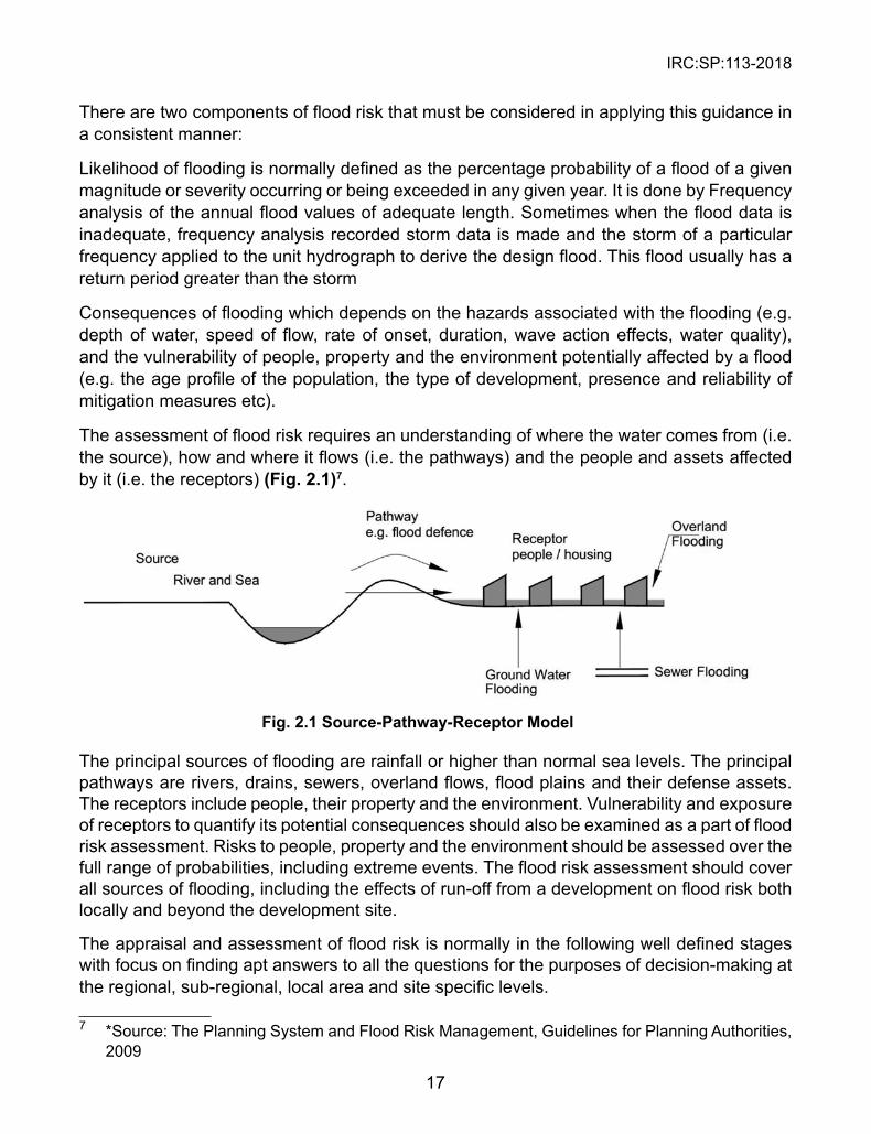
The assessment of flood risk requires an understanding of where the water comes from (i.e. the source), how and where it flows (i.e. the pathways) and the people and assets affected by it (i.e. the receptors) (Fig. 2.1)7.
Fig. 2.1 source-Pathway-Receptor Model
The principal sources of flooding are rainfall or higher than normal sea levels. The principal pathways are rivers, drains, sewers, overland flows, flood plains and their defense assets. The receptors include people, their property and the environment. Vulnerability and exposure of receptors to quantify its potential consequences should also be examined as a part of flood risk assessment. Risks to people, property and the environment should be assessed over the full range of probabilities, including extreme events. The flood risk assessment should cover all sources of flooding, including the effects of run-off from a development on flood risk both locally and beyond the development site.
The appraisal and assessment of flood risk is normally in the following well defined stages with focus on finding apt answers to all the questions for the purposes of decision-making at the regional, sub-regional, local area and site specific levels.
7 *Source: The Planning System and Flood Risk Management, Guidelines for Planning Authorities, 2009
IRC:SP:113-2018
18
Stage 1 Flood Risk Identification : Identification of flooding or surface water management issues at all levels that may warrant further investigation, mapping and data analysis.
stage 2 Initial Flood Risk Assessment : Pinpoint sources of flooding that may affect a plan area or the proposed development site and appraise the adequacy or otherwise of existing information and knowledge base for reliable assessment of the risk of flooding leading to the first order flood zone maps. Validated hydraulic models aids assessment of the potential impact of a development on flooding elsewhere and help outline the scope of possible mitigation measures as well as the requirements of the detailed assessment.
stage 3 Detailed Flood Risk Assessment : Analysis and understanding of all issues related to assessment of flood risk in sufficient detail leading to a quantitative appraisal of potential flood risk to a proposed or an existing development and of its potential impact on flood risk elsewhere. Given the detailed flood risk assessment, identification and engineering of the mitigation measures logically follow to reduce the impact on people and communities.
IRC:SP:113-2018
19
CHAPTER 3
FLOOD sTUDIEs
This chapter provides flood studies details on different topographical, hydrological, and river characteristics for assessing impact of floods in plains, hilly regions and coastal areas and flood investigation details.
3.1 Topographical Characteristics
Index plan showing the area affected in the past (including lands, villages and property) and the area likely to be affected in post-project conditions. The data to be collected for topographic study is:
u Contoured survey plan of the area prone to inundation. u Plan showing past river courses. u Plan of soil survey of the area where embankments are proposed. u Plan and section of the flood protection works already existing or executed. u Plan of structures likely to be affected due to construction of embankment as
a result of increase in flood level.
3. 2 Hydrological Characteristics
u Rainfall data for the past years 20 years. u Discharge or Flood carrying capacity of the stream. u Velocity of the stream.
3.3 River Characteristics
u Characteristics of river whether alluvial, incised, aggrading or degrading, meandering or braided. Qualitative and quantitative analysis of the silt of river at sites of proposed work or upstream.
u Nature of the soil of the bank and the bed at site of the proposed work. u Gauge and discharge data of the main river and its tributaries, preferably at
sites of proposed work or otherwise upstream. u Recorded maximum flood discharge, velocity and levels available with
corresponding river authorities. u Safe carrying capacity of the river (where work is proposed).
3.4 Road Development in Flood Plains
Construction of roads is essential to develop regions and ensure hassle-free access to the different places they connect. For a number of reasons, road development in a floodplain system requires a different approach to planning and technical design, compared to road development in areas that are not (regularly) inundated.
IRC:SP:113-2018
20
The main objectives of road development projects in flood plains are to u Enhance Regional Transportation and contribute in infrastructure, social,
economic and environmental development of region u Minimize flood vulnerability u Maintain flood plain hydraulics and ecology
3.5 Road Development in Hilly Areas
In hilly regions, river training is an important component in controlling of flash floods and general flood control, as well as in other activities such as ensuring the safe passage of a flood under a bridge. Hill roads along the river may also be in danger due to different problems created by it. Some of the problems created by river which create damage of hill roads are:
u Frequent changes in river course. u Avulsion of one river into another. u Development of natural cut-off. u Landslides in catchment -rise in silt load. u Aggradations of river bed -high flood levels -Flooding u Degradation of river bed downstream of a dam or a barrage. u Effects of flood embankment on the regime of rivers. u Effects of extraction of sand and boulders. u Effects of heavy urbanization along the river banks.Gullies are a highly visible form of soil erosion, with steep-sided, incised, drainage lines greater than 30 cm deep. In lay terms, the word ‘gully’ is often used to describe any drainage line flowing towards a stream. These drainage lines may pass through hill roads and often damage them
Roads, fences, and firebreaks should be situated in locations that do not readily divert overland runoff and concentrate it to areas that lead to gully erosion. The best place for a road is to follow a ridge line. An examination of satellite imagery in seriously eroded paddocks in the Burdekin catchment shows that graziers being aware of this consistently use ridge lines for access. Roads that run directly up and down the slope will divert or concentrate less runoff than those diagonal to the slope.
Roads should have a profile that does not concentrate overland runoff. Roads that are below normal ground level through constant use or inappropriate maintenance should be re-profiled to a form that does not concentrate overland runoff; alternatively, they should have drainage works incorporated to ensure runoff is dispersed onto stable areas. Associated table drains and mitre drains should have a trapezoidal shape with a flat bottom and not a triangular shape that is more conducive to eroding.
IRC:SP:113-2018
21
Gully control chutes are formed by battering gully heads to an acceptable slope depending on the method used to stabilize them. As well as for controlling gullies, chutes are used as by-washes in farm dams. They are also used to convey water over steep road batters, to control bed erosion in streams, and for urban developments such as sports fields.
Chutes require some form of energy dissipation at the outlet to help dissipate the energy gained when runoff flows down the chute. Chute failure often occurs when runoff fails to enter the chute properly. It is critical to control potential leaks and flow bypassing, especially at the chute entrance, and also to ensure suitable side walls contain the flows within the chute.
3.6 Road Development in Coastal Areas
As the sea level rises, the water depth increases and the wave base becomes deeper; waves reaching the coast have more energy and therefore can erode and transport greater quantities of sediment. Thus, the coast starts to adjust to the new sea level to maintain a dynamic equilibrium. The key physical parameters that need to be understood to identify coastal roads erosion as a problem in the coastal zone are:
l Coastal Geomorphology: Coastline type and sensitivity to coastal processes.
l Wind: The main force in wave generation; under the right environmental conditions, wind may transfer sediment from the beach environment landward on all open coastlines.
l Waves: They are the most important forces for sediment erosion and transport to the coastal zone. They introduce energy to the coast and also a series of currents that move sediment along the shore (Long shore drift) and normal to the shore (cross-shore transport). It is important to understand the movement of wave forms as well as water particles and their interaction with seabed material; also how the waves determine whether the coasts are erosive or accretional.
l Tides: They are influential in beach roads morph dynamics. They modulate wave action, controlling energy arriving on the coast and drive groundwater fluctuation and tidal currents. The interaction of groundwater with tides in the coastal forest environment is crucial in understanding why coastal forest clearance causes intensive coastal erosion in particular environments.
l Vegetation: Important for improving slope stability, consolidating sediments and providing some shoreline protection along the coastal roads.
Equally significant human activities that must be considered over the range of spatial and time scales are:
l Activities along the coastal roads: Building infrastructure via land reclamation or within sand dune areas and port/harbour development has a long-term impact on shoreline change; protective seawalls lead to erosion at the end of the structures, generate beach scouring at the toe of seawall and shorten the beach face. This can occur in the short term (less than five years)
IRC:SP:113-2018
22
or the long term (more than five years). Other structures such as groynes and jetties typically cause erosion down-drift of the structure within a short period of time (between five and ten years). Removal of dune vegetation and mangroves will expose low energy shorelines to increased energy and reduced sediment stability, causing erosion within five to ten years
l Activities within river catchments/watersheds: Dam construction and river diversion cause reduction of sediment supply to the coast that contributes to coastal erosion. The effects of dam and river diversion in terms of coastal erosion are not straightforward, but there are mid-to long-term impacts (20 to 100 years) with spatial scales approximately from one to 100 kilometers.
l Onshore and offshore activities: Sand and coral mining and dredging may affect coastal processes in various ways such as contributing to sediment deficit in the coastal system and modifying water depth that leads to altered wave refraction and longshore drift. The impact of these activities will be obvious within a short period of time (one to ten years).
Understanding the key processes of coastal dynamics and how the coasts function both in spatial and temporal time scales (short and long term), as well as human activities along the coast, within the river watershed and offshore is essential for managing coastal erosion because it may occur without reason. A quantitative understanding of changes in spatial and short- and long-term time scales is indispensable for the development of coastal roads.
3.7 Damage Mapping
Damage mapping of Flood prone area can be done by following methods. However any advance technology which provides the desired outputs can be adopted based on the requirement.
3.7.1 Technology-Satellite Based Radar Imaging Systems
Technology-Satellite Based Radar Imaging Systems- mapping and damage assessment
Radar (Radio Detection and Ranging) remote sensing is used to support a wide variety of science investigations including flood mapping, damage assessment, polar ice research, land use mapping, vegetation, biomass measurements, and soil moisture mapping etc. In addition, it is used to measure ground surface deformation caused by earthquakes, volcanic activities, floods, land subsidence, and slow landslides. These radar based applications are especially useful in assisting mitigation efforts following major natural disasters.
3.7.2 Drone and Hot Air Balloon Surveys
Inexpensive drones are capable of making sophisticated maps. Small, portable drones are quickly deployable. They carry lightweight digital cameras that can capture good quality images. These cameras can be set to take pictures at regular intervals, and digital memory is plentiful at low cost.
IRC:SP:113-2018
23
CHAPTER 4
FLOOD MANAGEMENT WORKs
4.1 Introduction
The frequency and intensity of floods have grown in India over the years primarily because of the increased encroachment in flood plains. These trends demand better preparedness at national, provincial and local levels to make sure that appropriate and effective response measures are taken during flood emergency to minimize the loss of life and property. This chapter discusses several measures aiming to reduce the risk of flooding by managing land, rivers, coastal systems and flood defenses. While we do everything to reduce the chance of flooding, one should always be cautious that it is a natural process and can never be completely eliminated.
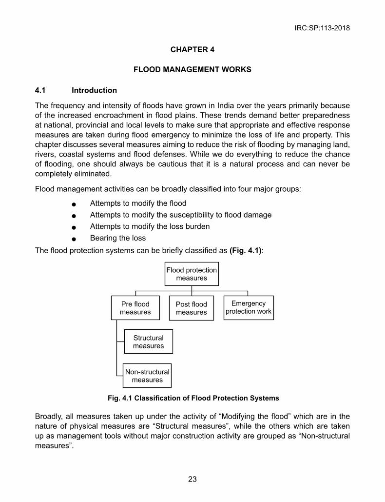
Flood management activities can be broadly classified into four major groups:
l Attempts to modify the flood l Attempts to modify the susceptibility to flood damage l Attempts to modify the loss burden l Bearing the loss The flood protection systems can be briefly classified as (Fig. 4.1):
Fig. 4.1 Classification of Flood Protection Systems
Broadly, all measures taken up under the activity of “Modifying the flood” which are in the nature of physical measures are “Structural measures”, while the others which are taken up as management tools without major construction activity are grouped as “Non-structural measures”.
IRC:SP:113-2018
24
4.2 Pre Flood Measures
Pre flood mode is determined by the aim of reducing flood risks in the long term. It can be characterized by the availability of time and resources. Depending on river morphology, river hydrology and characteristics, decision on the type of pre-response measure needs to be finalized. It could be a single measure or a combined measure which needs to be selected based on its suitability.
a. Flood conveyance structures designed to route flood waters away from areas of flooding risk via natural or artificial channels.
b. Flood storage structures that reduce the peak flood flows- Dams, reservoirs, check dams etc.
c. Flood defense and mitigation structures- levees, flood embankments, gryones, spurs, check dams etc.
d. Urban drainage system that increase infiltration e. Ecosystem management includes utilizing wet lands, creating environmental
buffers
4.2.1 Structural Protection measures
The general approach to tackle the problem of floods in the past has been in the form of physical measures with a view to prevent the flood waters from reaching potential damage centres. This approach had been extensively adopted in the Godavari, Krishna and Cauvery Deltas in South India and also in some areas of Indo-Gangetic plain.
The main thrust of the flood protection programme undertaken in India so far has been in the nature of taking structural measures like:
a. Embankments, flood walls and sea walls b. Dams and reservoirs c. Natural detention basin d. Channel improvement e Drainage improvement f. Diversion of flood waters
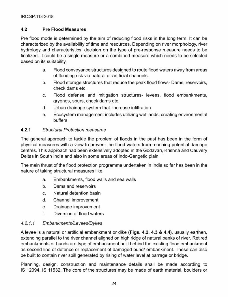
4.2.1.1 Embankments/Levees/Dykes
A levee is a natural or artificial embankment or dike (Figs. 4.2, 4.3 & 4.4), usually earthen, extending parallel to the river channel aligned on high ridge of natural banks of river. Retired embankments or bunds are type of embankment built behind the existing flood embankment as second line of defence or replacement of damaged bund/ embankment. These can also be built to contain river spill generated by rising of water level at barrage or bridge.
Planning, design, construction and maintenance details shall be made according to IS 12094, IS 11532. The core of the structures may be made of earth material, boulders or
IRC:SP:113-2018
25
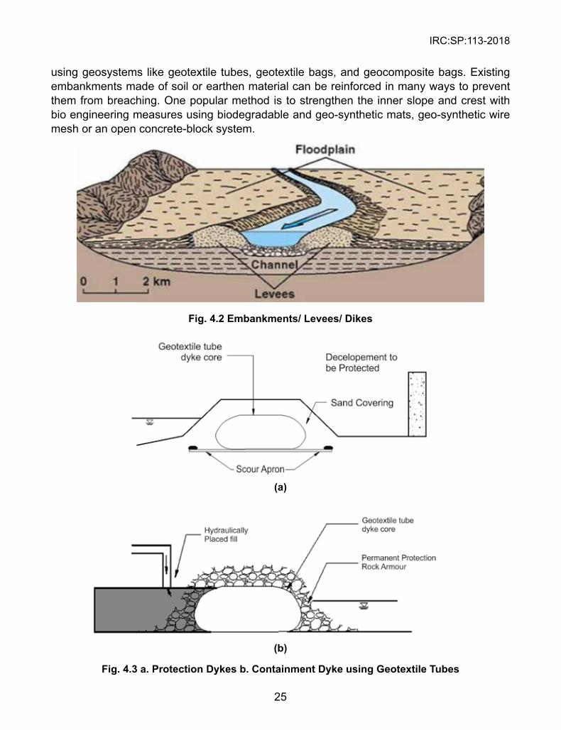
using geosystems like geotextile tubes, geotextile bags, and geocomposite bags. Existing embankments made of soil or earthen material can be reinforced in many ways to prevent them from breaching. One popular method is to strengthen the inner slope and crest with bio engineering measures using biodegradable and geo-synthetic mats, geo-synthetic wire mesh or an open concrete-block system.
Fig. 4.2 Embankments/ Levees/ Dikes
(a)
(b)
Fig. 4.3 a. Protection Dykes b. Containment Dyke using Geotextile Tubes
IRC:SP:113-2018
26
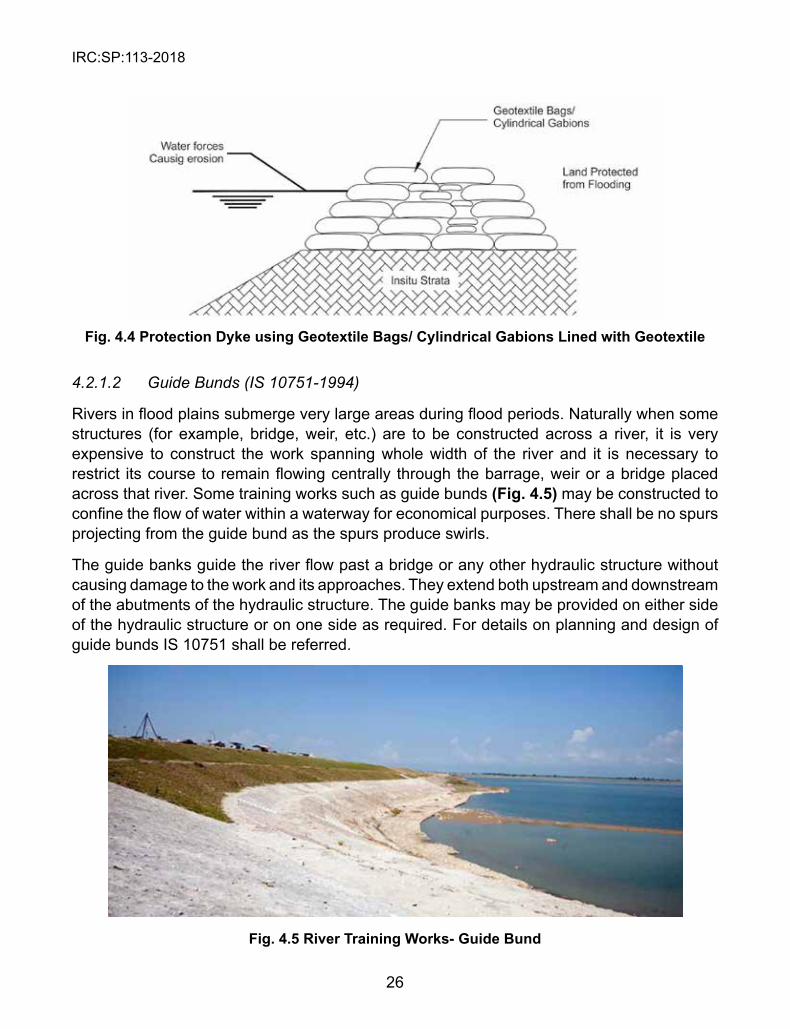
Fig. 4.4 Protection Dyke using Geotextile Bags/ Cylindrical Gabions Lined with Geotextile
4.2.1.2 Guide Bunds (IS 10751-1994)
Rivers in flood plains submerge very large areas during flood periods. Naturally when some structures (for example, bridge, weir, etc.) are to be constructed across a river, it is very expensive to construct the work spanning whole width of the river and it is necessary to restrict its course to remain flowing centrally through the barrage, weir or a bridge placed across that river. Some training works such as guide bunds (Fig. 4.5) may be constructed to confine the flow of water within a waterway for economical purposes. There shall be no spurs projecting from the guide bund as the spurs produce swirls.
The guide banks guide the river flow past a bridge or any other hydraulic structure without causing damage to the work and its approaches. They extend both upstream and downstream of the abutments of the hydraulic structure. The guide banks may be provided on either side of the hydraulic structure or on one side as required. For details on planning and design of guide bunds IS 10751 shall be referred.
Fig. 4.5 River Training Works- Guide Bund
IRC:SP:113-2018
27
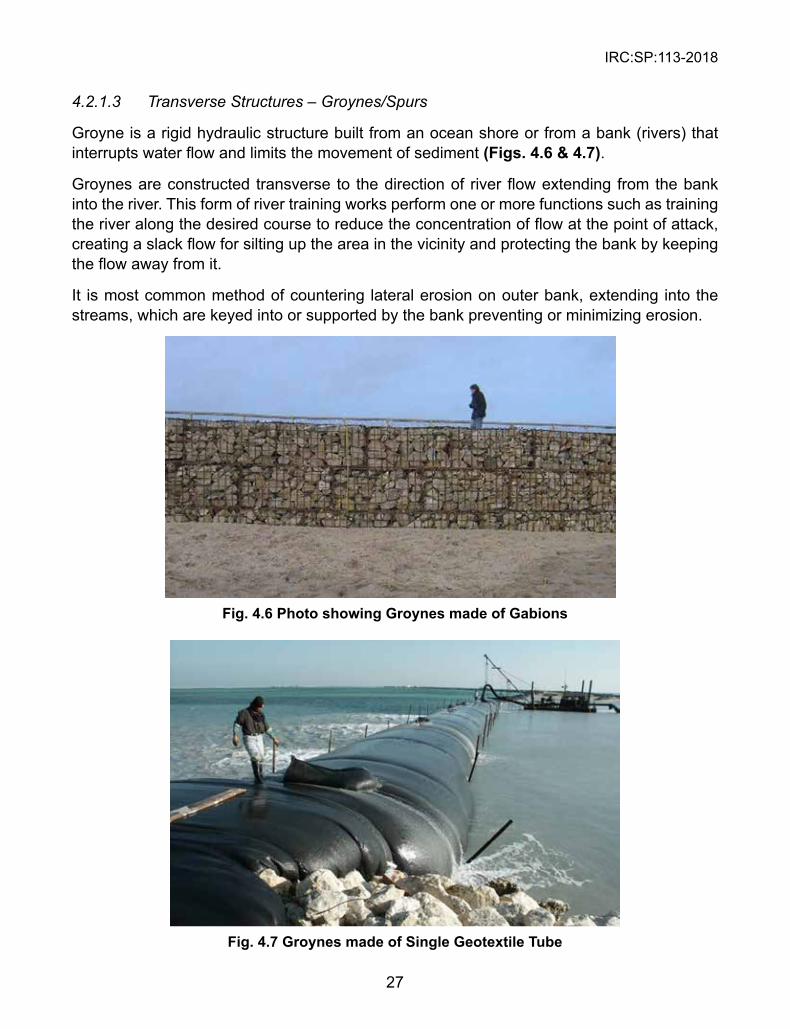
4.2.1.3 Transverse Structures – Groynes/Spurs
Groyne is a rigid hydraulic structure built from an ocean shore or from a bank (rivers) that interrupts water flow and limits the movement of sediment (Figs. 4.6 & 4.7).
Groynes are constructed transverse to the direction of river flow extending from the bank into the river. This form of river training works perform one or more functions such as training the river along the desired course to reduce the concentration of flow at the point of attack, creating a slack flow for silting up the area in the vicinity and protecting the bank by keeping the flow away from it.
It is most common method of countering lateral erosion on outer bank, extending into the streams, which are keyed into or supported by the bank preventing or minimizing erosion.
Fig. 4.6 Photo showing Groynes made of Gabions
Fig. 4.7 Groynes made of single Geotextile Tube
IRC:SP:113-2018
28
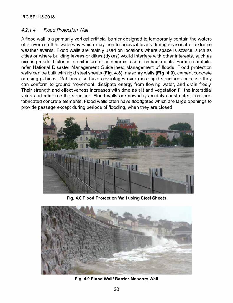
4.2.1.4 Flood Protection Wall
A flood wall is a primarily vertical artificial barrier designed to temporarily contain the waters of a river or other waterway which may rise to unusual levels during seasonal or extreme weather events. Flood walls are mainly used on locations where space is scarce, such as cities or where building levees or dikes (dykes) would interfere with other interests, such as existing roads, historical architecture or commercial use of embankments. For more details, refer National Disaster Management Guidelines; Management of floods. Flood protection walls can be built with rigid steel sheets (Fig. 4.8), masonry walls (Fig. 4.9), cement concrete or using gabions. Gabions also have advantages over more rigid structures because they can conform to ground movement, dissipate energy from flowing water, and drain freely. Their strength and effectiveness increases with time as silt and vegetation fill the interstitial voids and reinforce the structure. Flood walls are nowadays mainly constructed from pre-fabricated concrete elements. Flood walls often have floodgates which are large openings to provide passage except during periods of flooding, when they are closed.
Fig. 4.8 Flood Protection Wall using steel sheets
Fig. 4.9 Flood Wall/ Barrier-Masonry Wall
IRC:SP:113-2018
29
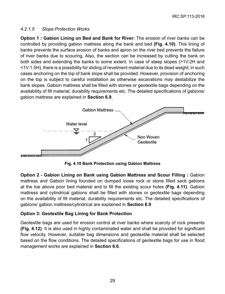
4.2.1.5 Slope Protection Works
Option 1 : Gabion Lining on Bed and Bank for River: The erosion of river banks can be controlled by providing gabion mattress along the bank and bed (Fig. 4.10). This lining of banks prevents the surface erosion of banks and apron on the river bed prevents the failure of river banks due to scouring. Also, the section can be increased by cutting the bank on both sides and extending the banks to some extent. In case of steep slopes (>1V:2H and <1V:1.5H), there is a possibility for sliding of revetment material due to its dead weight; in such cases anchoring on the top of bank slope shall be provided. However, provision of anchoring on the top is subject to careful installation as otherwise excavations may destabilize the bank slopes. Gabion mattress shall be filled with stones or geotextile bags depending on the availability of fill material, durability requirements etc. The detailed specifications of gabions/ gabion mattress are explained in section 6.9.
Fig. 4.10 Bank Protection using Gabion Mattress
Option 2 - Gabion Lining on Bank using Gabion Mattress and scour Filling : Gabion mattress and Gabion lining founded on dumped loose rock or stone filled sack gabions at the toe above poor bed material and to fill the existing scour holes (Fig. 4.11). Gabion mattress and cylindrical gabions shall be filled with stones or geotextile bags depending on the availability of fill material, durability requirements etc. The detailed specifications of gabions/ gabion mattress/cylindrical are explained in section 6.9
Option 3: Geotextile Bag Lining for Bank Protection
Geotextile bags are used for erosion control at river banks where scarcity of rock presents (Fig. 4.12). It is also used in highly contaminated water and shall be provided for significant flow velocity. However, suitable bag dimensions and geotextile material shall be selected based on the flow conditions. The detailed specifications of geotextile bags for use in flood management works are explained in section 6.6.
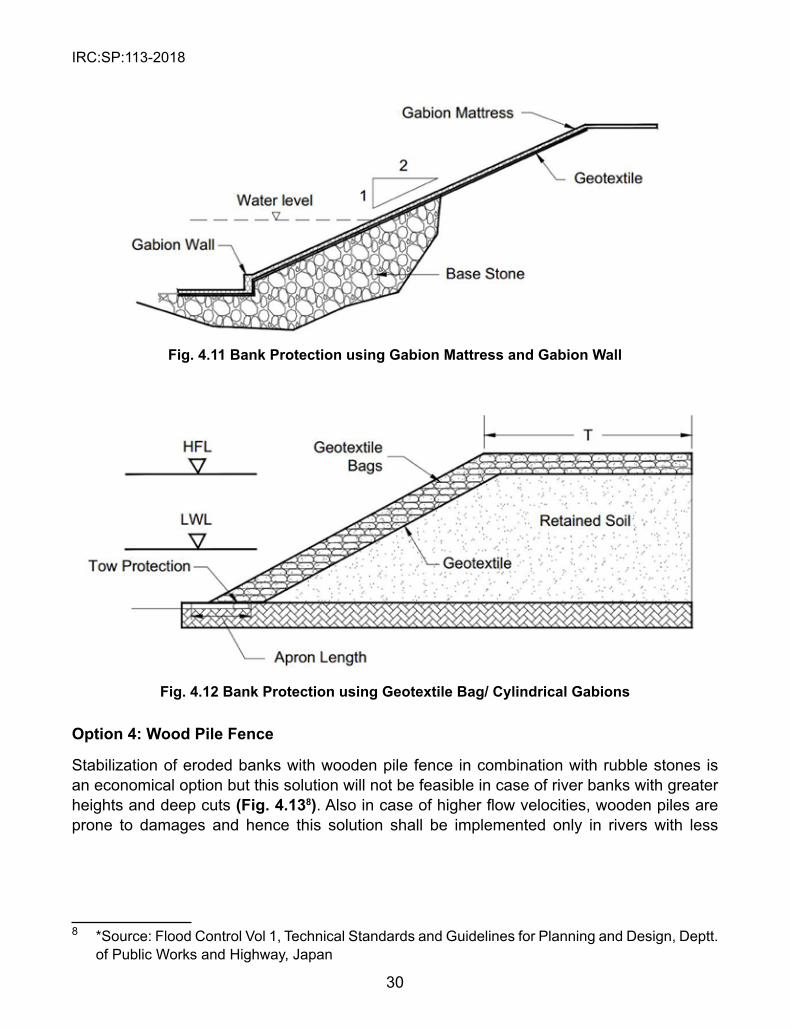
IRC:SP:113-2018
30
Fig. 4.11 Bank Protection using Gabion Mattress and Gabion Wall
Fig. 4.12 Bank Protection using Geotextile Bag/ Cylindrical Gabions
Option 4: Wood Pile Fence
Stabilization of eroded banks with wooden pile fence in combination with rubble stones is an economical option but this solution will not be feasible in case of river banks with greater heights and deep cuts (Fig. 4.138). Also in case of higher flow velocities, wooden piles are prone to damages and hence this solution shall be implemented only in rivers with less
8 *Source: Flood Control Vol 1, Technical Standards and Guidelines for Planning and Design, Deptt. of Public Works and Highway, Japan
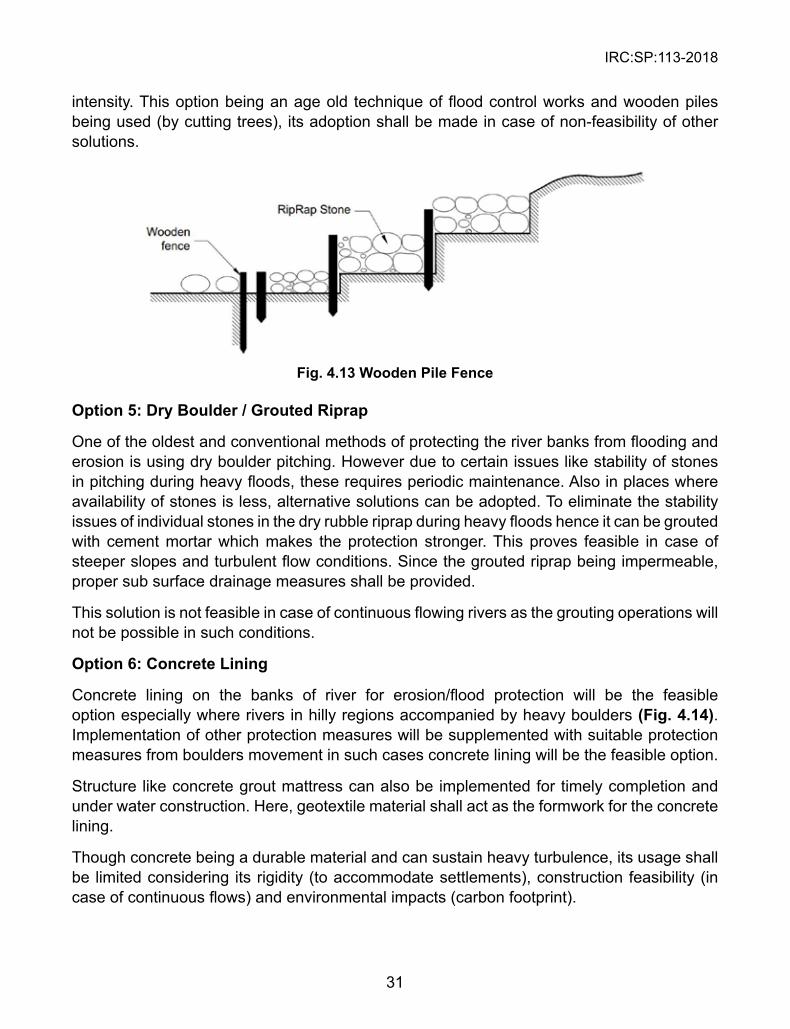
IRC:SP:113-2018
31
intensity. This option being an age old technique of flood control works and wooden piles being used (by cutting trees), its adoption shall be made in case of non-feasibility of other solutions.
Fig. 4.13 Wooden Pile Fence
Option 5: Dry Boulder / Grouted Riprap
One of the oldest and conventional methods of protecting the river banks from flooding and erosion is using dry boulder pitching. However due to certain issues like stability of stones in pitching during heavy floods, these requires periodic maintenance. Also in places where availability of stones is less, alternative solutions can be adopted. To eliminate the stability issues of individual stones in the dry rubble riprap during heavy floods hence it can be grouted with cement mortar which makes the protection stronger. This proves feasible in case of steeper slopes and turbulent flow conditions. Since the grouted riprap being impermeable, proper sub surface drainage measures shall be provided.
This solution is not feasible in case of continuous flowing rivers as the grouting operations will not be possible in such conditions.
Option 6: Concrete Lining
Concrete lining on the banks of river for erosion/flood protection will be the feasible option especially where rivers in hilly regions accompanied by heavy boulders (Fig. 4.14). Implementation of other protection measures will be supplemented with suitable protection measures from boulders movement in such cases concrete lining will be the feasible option.
Structure like concrete grout mattress can also be implemented for timely completion and under water construction. Here, geotextile material shall act as the formwork for the concrete lining.
Though concrete being a durable material and can sustain heavy turbulence, its usage shall be limited considering its rigidity (to accommodate settlements), construction feasibility (in case of continuous flows) and environmental impacts (carbon footprint).
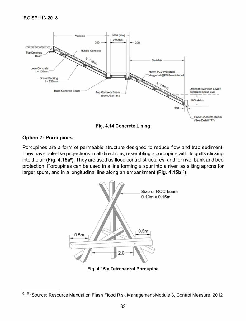
IRC:SP:113-2018
32
9,10 *Source: Resource Manual on Flash Flood Risk Management-Module 3, Control Measure, 2012
Fig. 4.14 Concrete Lining
Option 7: Porcupines
Porcupines are a form of permeable structure designed to reduce flow and trap sediment. They have pole-like projections in all directions, resembling a porcupine with its quills sticking into the air (Fig. 4.15a9). They are used as flood control structures, and for river bank and bed protection. Porcupines can be used in a line forming a spur into a river, as silting aprons for larger spurs, and in a longitudinal line along an embankment (Fig. 4.15b10).
Fig. 4.15 a Tetrahedral Porcupine
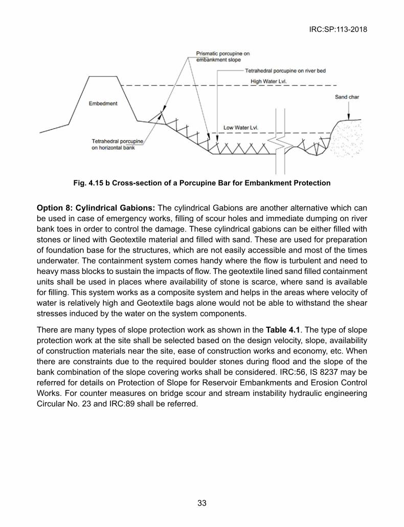
IRC:SP:113-2018
33
Fig. 4.15 b Cross-section of a Porcupine Bar for Embankment Protection
Option 8: Cylindrical Gabions: The cylindrical Gabions are another alternative which can be used in case of emergency works, filling of scour holes and immediate dumping on river bank toes in order to control the damage. These cylindrical gabions can be either filled with stones or lined with Geotextile material and filled with sand. These are used for preparation of foundation base for the structures, which are not easily accessible and most of the times underwater. The containment system comes handy where the flow is turbulent and need to heavy mass blocks to sustain the impacts of flow. The geotextile lined sand filled containment units shall be used in places where availability of stone is scarce, where sand is available for filling. This system works as a composite system and helps in the areas where velocity of water is relatively high and Geotextile bags alone would not be able to withstand the shear stresses induced by the water on the system components.
There are many types of slope protection work as shown in the Table 4.1. The type of slope protection work at the site shall be selected based on the design velocity, slope, availability of construction materials near the site, ease of construction works and economy, etc. When there are constraints due to the required boulder stones during flood and the slope of the bank combination of the slope covering works shall be considered. IRC:56, IS 8237 may be referred for details on Protection of Slope for Reservoir Embankments and Erosion Control Works. For counter measures on bridge scour and stream instability hydraulic engineering Circular No. 23 and IRC:89 shall be referred.
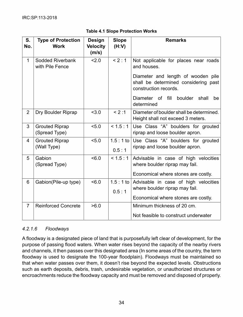
IRC:SP:113-2018
34
Table 4.1 slope Protection Works
s. No.
Type of Protection Work
Design Velocity
(m/s)
slope (H:V)
Remarks
1 Sodded Riverbank with Pile Fence
<2.0 < 2 : 1 Not applicable for places near roads and houses.
Diameter and length of wooden pile shall be determined considering past construction records.
Diameter of fill boulder shall be determined
2 Dry Boulder Riprap <3.0 < 2 :1 Diameter of boulder shall be determined. Height shall not exceed 3 meters.
3 Grouted Riprap (Spread Type)
<5.0 < 1.5 : 1 Use Class “A” boulders for grouted riprap and loose boulder apron.
4 Grouted Riprap (Wall Type)
<5.0 1.5 : 1 to
0.5 : 1
Use Class “A” boulders for grouted riprap and loose boulder apron.
5 Gabion (Spread Type)
<6.0 < 1.5 : 1 Advisable in case of high velocities where boulder riprap may fail.
Economical where stones are costly.6 Gabion(Pile-up type) <6.0 1.5 : 1 to
0.5 : 1
Advisable in case of high velocities where boulder riprap may fail.
Economical where stones are costly.7 Reinforced Concrete >6.0 Minimum thickness of 20 cm.
Not feasible to construct underwater
4.2.1.6 Floodways
A floodway is a designated piece of land that is purposefully left clear of development, for the purpose of passing flood waters. When water rises beyond the capacity of the nearby rivers and channels, it then passes over this designated area (In some areas of the country, the term floodway is used to designate the 100-year floodplain). Floodways must be maintained so that when water passes over them, it doesn’t rise beyond the expected levels. Obstructions such as earth deposits, debris, trash, undesirable vegetation, or unauthorized structures or encroachments reduce the floodway capacity and must be removed and disposed of properly.
IRC:SP:113-2018
35
4.2.2 Non-Structural Protection Measures
Non-structural measures strive to keep people away from flood waters. It contemplates the use of flood plains judiciously, simultaneously permitting vacating of the same for use by the river whenever the situation demands. This technique allows the use of flood plains by reducing the disaster dimension, while retaining its beneficial effects.
4.2.2.1 Flood Forecasting and Warning
Flood forecasting activities in India made a small beginning in November 1958 when the Central Water Commission created a Flood Forecasting Unit for flood forecasting for the river Yamuna at Delhi, the National Capital. The disastrous floods in 1968 in many parts of the country necessitated the setting up of forecasting centers on interstate rivers. Networks of flood forecasting stations established in major and interstate river basins. In that total Flood Forecasting Stations 175, Inflow 28, Stage 147. These are issued for different areas mostly by the Central Water Commission/Meteorological Department and by the State Irrigation/ Flood Department. However, an effective Warning System is one that can release warning in advance, i.e. 72hrs, 48hrs and 24hrs.
4.2.2.2 Flood Routing Techniques
Flood routing is the technique of determining the flood hydrograph at a section of a river by utilizing the data of flood flow at one or more upstream sections. The hydrologic analysis of problems such as flood forecasting, flood protection, reservoir design and spillway design invariably include flood routing. In these applications, two broad categories of routing can be recognized. These are:
1. Reservoir routing, and 2. Channel routing A variety of routing methods are available and they can be broadly classified into two categories as:
1. Hydrologic routing and 2. Hydraulic routing Hydrologic-routing methods employ essentially the equation of continuity. Hydraulic methods, on the other hand, employ the continuity equation together with the equation of motion of unsteady flood flow.
Flood Forecasting: Flood retention reservoirs, where available, can play a crucial role in flood control. For optimum operation of such reservoirs, reliable forecast estimates of the incoming flood flow over the time shall be needed and these are required for filling and emptying the reservoir. In case of most reservoirs, whose primary purpose is water supply, flood operation is an important component of their management. The Minimum Draw Down Level (MDDL) is fixed from design considerations to meet the objectives of water use. Most floods are expected to occur in the wet season, and even if the reservoir is full, some attenuation of the
IRC:SP:113-2018
36
incoming flood hydrograph will occur due to the size of the reservoir, the out flowing flood being released through either uncontrolled or controlled spillways. Reservoirs are designed with particular characteristics defined by Storage and outflow up to a Maximum Water Level (MWL). However, in case of large floods, this design capacity may be exceeded and water may have to be released. Depending on the flooding scenario, the downstream area of the dam which may already be in critical situation during wet season, such flood release from reservoirs may have devastating effects. As such, effective management and control measures must be devised.
4.2.2.3 BoostingofPumpingCapacitybyInstallationofArtificialEmergencyDrainageatCritical Locations.
Floodwater pumping stations should be designed to operate automatically with appropriate type of pumps which are controlled by water level sensors installed in the pump sump. Accumulated storm water from the flood storage facilities is pumped to the nearest main drainage channel outside the polder (a piece of low-lying land reclaimed from the sea or a river and protected by dykes).
A good appearance is one of the functional requirements of pumping stations. This is particularly important for pumping stations located in urban areas and exposed to public views. For those in village areas, local residents should be enquired as far as possible. To enhance the appearance of pumping stations, external finishes are usually provided for superstructure above ground. The construction cost for finishes together with the future maintenance cost should be taken into account in selecting the type of finishes to be used. To save cost, fair concrete finishes may be considered for internal walls of unmanned pumping station. However, the floor of pumping station should be painted with anti-skidding coats.
4.2.2.4 Design Capacity
The design capacity for all duty pumps should be adequate to handle rainstorm runoffs collected inside the polder with a return period of 10 years. Stand-by pumps must be available and should be able to automatically take over the failed duty pumps. Both duty pumps and stand-by pumps should be interchangeable. The standby pumps should be so designed such that they can also be activated in case of exceptionally severe rainstorms.
In the determination of the pumping requirements, the following guidelines should be followed:
(a) The design freeboard for floodwater storage facilities should be 300 mm for a storm with a 10-year return period.
(b) Combinations of stand-by pumps and duty pumps can be formulated for an individual village flood protection scheme so that if any of the duty pumps in the station becomes inoperable due to routine maintenance or mechanical failure, the design capacity of the pumping station can still be maintained. As a simple rule, the total capacity of the stand-by pumps should be at least 30% of the total capacity of the duty pumps.
IRC:SP:113-2018
37
(c) The total maximum pumping capacity (both duty pumps plus stand-by pumps) of a pumping station should be able to accommodate a storm with a 50-year return period.
The flood depths inside the polder during a 50-year and a 200-year rainstorm under the proper functioning of duty pumps and the floodwater storage facilities should be checked.
If the flood depth is considered intolerable, the capacity of the storage facilities should be increased to suit.
4.2.2.5 Integrated River Basin Approach
Effective measures for flood prevention and protection have to be taken in the level of river basins and that it is necessary to take into account interdependence and interaction of effects of individual measures implemented along water courses. It is absolutely necessary to organize the water management systems and improve forecasting, flood defense measures and crisis management on a river basin basis, cutting across regional boundaries and country borders. So a sustainable way by taking a river basin integrated and long term view, probably of the order of 50 or 100 years.
4.2.2.6 Drainage System
A storm drainage system is a system receiving, conveying, and controlling storm water runoff in response to precipitation and snowmelt. Such systems include: ditches, culverts, swales, subsurface interceptor drains, roadways, curb and gutters, catch basins, manholes, pipes, attenuation ponds and service lateral lines. It is designed to convey runoff from frequent storms (e.g., up to 2 or 5 year storms). The main purpose of this system is to minimize storm water ponding at intersections and pedestrian crossings which may cause inconvenience to both pedestrians and motorists so it is also called the convenience system. The major drainage system comprises the natural streams and valleys and man-made streets, channels and ponds. It is designed to accommodate runoff from less frequent storms (e.g., 100 year or the Regional storms). The main purpose is to essentially eliminate the risk of loss of life and property damage due to flooding. There have been many methodologies developed earlier to estimate the total runoff volume, the peak rate runoff and the run off hydrograph from land surfaces under a variety of conditions like runoff curve number method, small storm hydrology method, infiltration model methods etc. for earlier stages and Rational method, SCS method, modified Rational method in present stages.
4.2.2.6.1 Storm Water Management to counter Anthropogenic Impacts.
Managing the quantity and quality of storm water is termed, “Storm Water Management.” The term Best Management Practice (BMP) or storm water control measure is often used to refer to both structural or engineered control devices and systems (e.g. retention ponds) to treat or store polluted storm water, as well as operational or procedural practices (e.g. street sweeping). Storm water management includes both technical and institutional aspects.
IRC:SP:113-2018
38
4.2.2.6.2 Interception by tree canopy, vegetation, natural ponds –depression storage in forested catchments.
Trees and forests play an incredible role in reducing storm water in several ways and removing or filtering pollutants that would otherwise wind up in our waterways.
l Canopy Interception and Infiltration: Forests filter and regulate the flow of water, in large part due to their leafy canopy that intercepts rainfall, slowing its fall to the ground and the forest floor, which acts like an enormous sponge, typically absorbing up to 450 mm of precipitation (depending on soil composition) before gradually releasing it to natural channels and recharging ground water. Average interception of rainfall by a forest canopy ranges from 10-40% depending on species, time of year, and precipitation rates per storm event. In urban and suburban settings a single deciduous tree can intercept from 1900 to 2900 litres per year; and a mature evergreen can intercept more than 1500 litres per year. Even young, small trees help.
4.2.2.6.3 Leakage from water distribution (pressurized pipes-low losses high volumes) and waste water and sewerage networks buried under roads and road embankments.
Systematic leakage-control programs have two main components: water audits and leak-detection surveys. In recent years, significant efforts have been made to develop water audit procedures and leak-detection methods. As a result, water system operators now have several well established procedures and modern equipment to help them control water leakage.
4.2.2.6.4 Management of storm water runoffs by source control; conveyance capacity of natural channels-building new drains surface and underground
A storm water conveyance channel is a permanent waterway, designed to convey storm water runoff. The channel is lined with vegetation or riprap, or, in limited cases, gabions, which extend up the side slopes to design flow depth. This practice provides a means of transporting concentrated surface runoff without causing erosion or flooding. Channels, including road ditches that are constructed as part of a development to transport surface runoff generally are included in this practice.
Properly designed storm water conveyance channels are effective in preventing erosion caused by concentrated flows. They can significantly reduce or eliminate sediment loads originating in the channel area. Channel design and stability will differ depending on the soil type and topography. In hilly terrain, for example, velocities may most often be such that grass-lined channels won’t work effectively and riprap will be needed instead. If deep cuts are required on hilly terrain, an above-ground channel may be impractical.
The design of storm water conveyance channels should be done by registered professional engineers.
IRC:SP:113-2018
39
1. shapeThere are two types of channels to choose from: parabolic and trapezoidal. Parabolic channels are more similar to the shape of natural channels and are often used where space is available for a wide, shallow channel to allow low velocities. Trapezoidal channels are normally used where deeper channels are needed to carry large flows. Trapezoidal design works well with riprap or other structural linings, and tends to revert to a parabolic shape over time. V-shaped channels are not to be used because they are similar to the shape of gullies.
2. side slopesVegetated slopes in urban areas should be 4:1 or flatter for maintenance reasons. Slopes can be steeper for structurally lined channels as long as they are within the capability of the soil and structural lining. For trapezoidal channels with a bottom width greater than 4.5 m, the center should be lowered 150 mm to prevent meandering during low flows.
3. CapacityUnless local storm water requirements indicate otherwise, all storm water channels should be designed to contain at least the peak flow from a 10-year frequency storm. In areas where flooding of the channel will cause damage to property owners, the channel capacity should be increased. The capacity of the channel should not exceed the capacity of the outlet area. Property damage or safety hazards may result if channel capacity is exceeded. Extra capacity may be needed for areas where sediment is expected to accumulate. An extra 100 to 150 mm of depth is recommended.
4. Velocity Channels should be designed so that the velocity of flow expected from the design storm does not exceed the permissible velocity for the type of lining used. Design velocities should be appropriate for the type of liner selected.
5. DepthThe design water surface elevation of a channel receiving water from diversions or other tributary channels should be equal to or less than the design water surface elevation of the diversion or other tributary channel at the point of intersection.
6. Cross-sectionsThe top width of parabolic and grass-lined channels should not exceed 9 m, and the bottom width of trapezoidal, grass-lined channels should not exceed 4.5 m unless multiple or divided waterways, riprap center, or other means are provided to control meandering of low flows. Freeboard: Where good vegetative cover cannot be grown adjacent to the lined side slopes, a minimum freeboard of 1m above design flow depth should be incorporated into the lined waterway.
7. Building New Drains
Planning for new drainage infrastructure and upgrading of existing drains is done in consultation with the key planning agencies and authorities and to continuously monitor upcoming developments and upgrade the drains and canals promptly to:
IRC:SP:113-2018
40
a. Alleviate flooding, where constrictions/bottlenecks in existing drains/canals are identified and removed,
b. Cope with increased runoff from developments and to meet the existing drainage standards, and
c. Rehabilitate deteriorating drains.
4.3 Emergency Flood Protection Measures
Emergency flood protection measures are temporary in nature and are implemented between the flood warning and the flood event to protect the areas from floodwaters.
Any response to flood emergencies must be rapid and effective in order to restore the natural status of the impacted region, to contain the damage and lives can be restarted. There is little time to react to sudden effects of landslides and floods in remote and hard to reach areas.
To deal with flood emergency situations, speed and efficiency of installation are vital. It should be:
l Rapid and simple to deploy l Flexible and light l Simple connection between units l Uses locally available fill material l Easy transportation l Re-usable.Geotextile bags, geocomposite containment units, temporary flood barriers, and flood wrapping systems are common emergency flood protection measures and are described in the following subsections.
4.3.1 Geotextile Bags Filled with Sand
Temporary walls constructed of sand/geotextile bags can be used to protect structures from flooding or provide additional height to existing levee systems when flood waters reach critical levels. However, unless emergency placement is planned well in advance under the direction of trained personnel, most sandbag barriers are not constructed in accordance with proper practices, leading to leakage and failures. Properly filled and placed, geotextile bags can act as a barrier to divert moving water around, instead of through, buildings (Fig.4.1611). Geotextile bags can also be used to prevent overtopping of leveled streams; to divert current flow to a specific area; to contain seepage behind levees; and to provide weight on back slopes of levees, poly sheeting, and other barriers.
To be effective, sand/geotextile bags and sand should be stockpiled and checked regularly to ensure that the sandbags have not deteriorated. Sand and/or geotextile filled sandbags
11 *Source: Resource Manual on Flash Flood Risk Management-Module 3, Control Measure, 2012
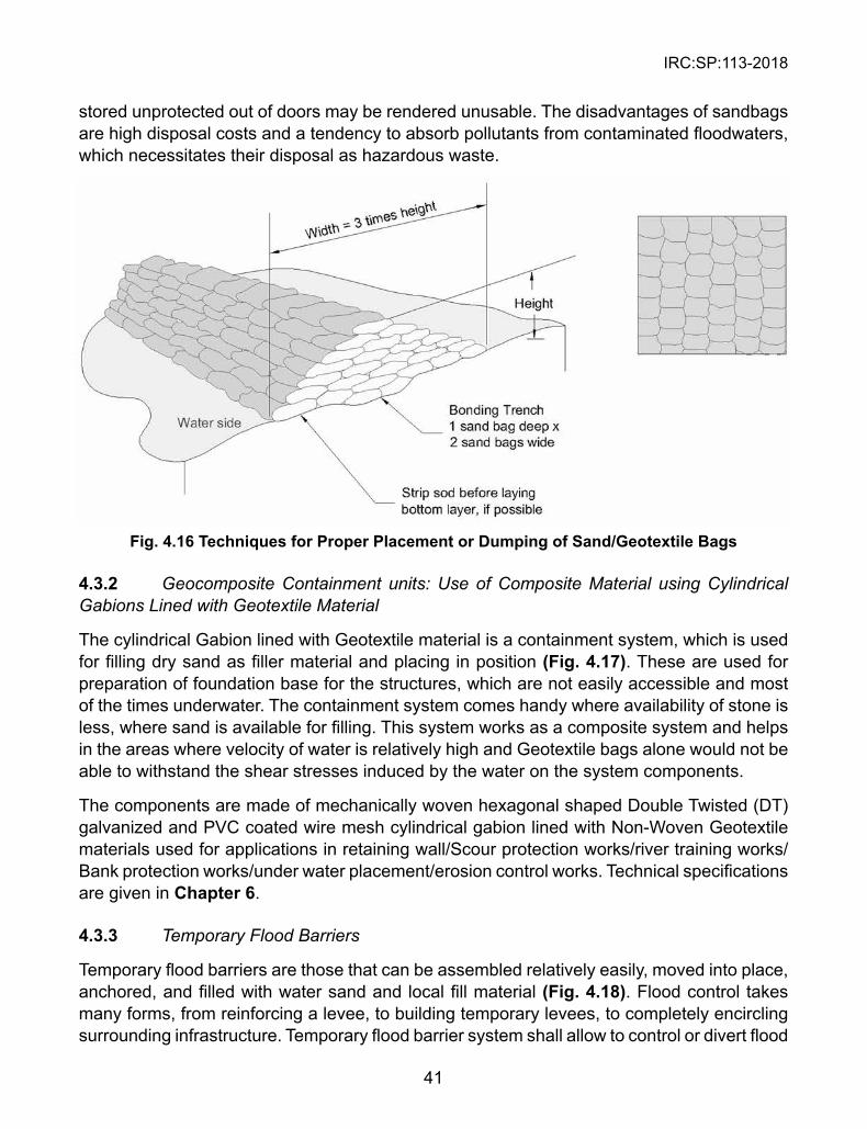
IRC:SP:113-2018
41
stored unprotected out of doors may be rendered unusable. The disadvantages of sandbags are high disposal costs and a tendency to absorb pollutants from contaminated floodwaters, which necessitates their disposal as hazardous waste.
Fig. 4.16 Techniques for Proper Placement or Dumping of sand/Geotextile Bags
4.3.2 Geocomposite Containment units: Use of Composite Material using Cylindrical Gabions Lined with Geotextile Material
The cylindrical Gabion lined with Geotextile material is a containment system, which is used for filling dry sand as filler material and placing in position (Fig. 4.17). These are used for preparation of foundation base for the structures, which are not easily accessible and most of the times underwater. The containment system comes handy where availability of stone is less, where sand is available for filling. This system works as a composite system and helps in the areas where velocity of water is relatively high and Geotextile bags alone would not be able to withstand the shear stresses induced by the water on the system components.
The components are made of mechanically woven hexagonal shaped Double Twisted (DT) galvanized and PVC coated wire mesh cylindrical gabion lined with Non-Woven Geotextile materials used for applications in retaining wall/Scour protection works/river training works/Bank protection works/under water placement/erosion control works. Technical specifications are given in Chapter 6.
4.3.3 Temporary Flood Barriers
Temporary flood barriers are those that can be assembled relatively easily, moved into place, anchored, and filled with water sand and local fill material (Fig. 4.18). Flood control takes many forms, from reinforcing a levee, to building temporary levees, to completely encircling surrounding infrastructure. Temporary flood barrier system shall allow to control or divert flood
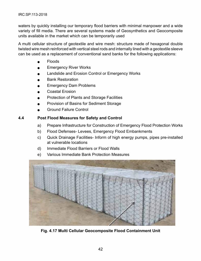
IRC:SP:113-2018
42
waters by quickly installing our temporary flood barriers with minimal manpower and a wide variety of fill media. There are several systems made of Geosynthetics and Geocomposite units available in the market which can be temporarily used
A multi cellular structure of geotextile and wire mesh: structure made of hexagonal double twisted wire mesh reinforced with vertical steel rods and internally lined with a geotextile sleeve can be used as a replacement of conventional sand banks for the following applications:
l Floods l Emergency River Works l Landslide and Erosion Control or Emergency Works l Bank Restoration l Emergency Dam Problems l Coastal Erosion l Protection of Plants and Storage Facilities l Provision of Basins for Sediment Storage l Ground Failure Control
4.4 Post Flood Measures for safety and Control
a) Prepare Infrastructure for Construction of Emergency Flood Protection Works b) Flood Defenses- Levees, Emergency Flood Embankments c) Quick Drainage Facilities- Inform of high energy pumps, pipes pre-installed
at vulnerable locations d) Immediate Flood Barriers or Flood Walls e) Various Immediate Bank Protection Measures
Fig. 4.17 Multi Cellular Geocomposite Flood Containment Unit
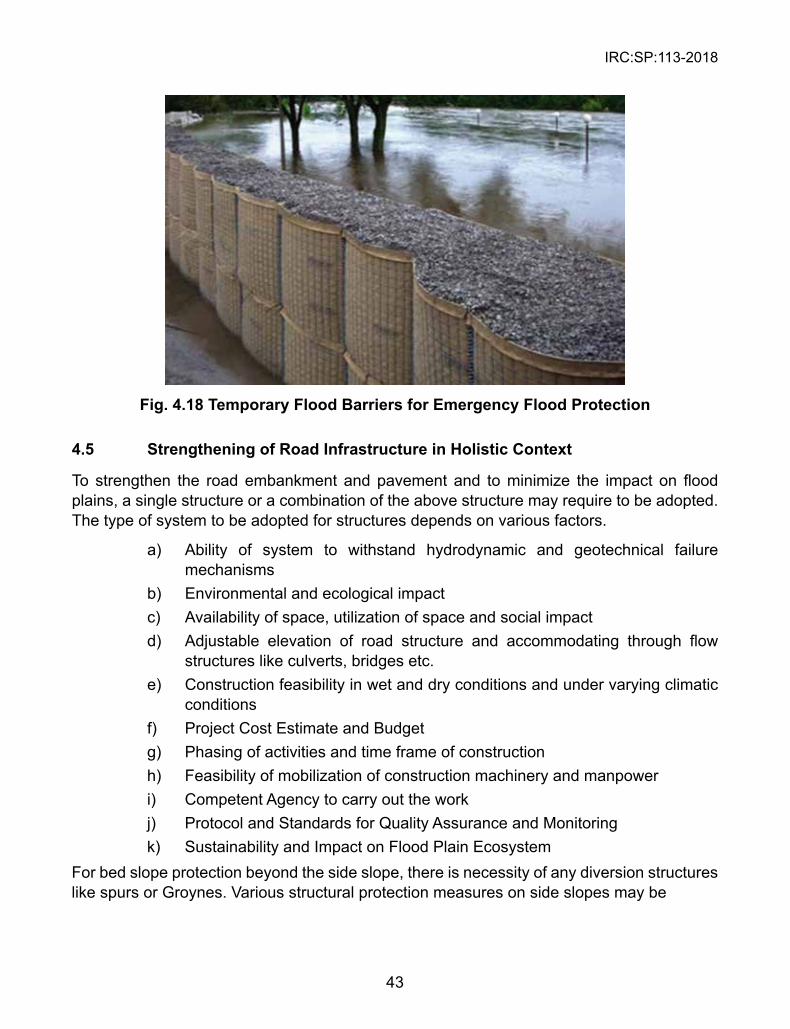
IRC:SP:113-2018
43
Fig. 4.18 Temporary Flood Barriers for Emergency Flood Protection
4.5 strengthening of Road Infrastructure in Holistic Context
To strengthen the road embankment and pavement and to minimize the impact on flood plains, a single structure or a combination of the above structure may require to be adopted. The type of system to be adopted for structures depends on various factors.
a) Ability of system to withstand hydrodynamic and geotechnical failure mechanisms
b) Environmental and ecological impact c) Availability of space, utilization of space and social impact d) Adjustable elevation of road structure and accommodating through flow
structures like culverts, bridges etc. e) Construction feasibility in wet and dry conditions and under varying climatic
conditions f) Project Cost Estimate and Budget g) Phasing of activities and time frame of construction h) Feasibility of mobilization of construction machinery and manpower i) Competent Agency to carry out the work j) Protocol and Standards for Quality Assurance and Monitoring k) Sustainability and Impact on Flood Plain EcosystemFor bed slope protection beyond the side slope, there is necessity of any diversion structures like spurs or Groynes. Various structural protection measures on side slopes may be
IRC:SP:113-2018
44
l Rip-Rap l Concrete Lining, l Stone Filled Gabion Mattress l Geotextile Bags l Geotextile Tubes l Grout Mattress l Sand Mattress l Erosion Control Mat l Pre-filled Sack Gabions
4.5.1 Road/ Track Approaches
Potential increases in flood levels due to obstruction by road or track approaches to bridges need to be considered. Where the road or track approaches are at natural surface level or floodplain level, the structure would not obstruct flood flows. Where the road or track approaches are above natural surface level or floodplain level, an assessment of the flows across the floodplain is needed. Detailed hydraulic modeling (Numerical Studies) would be a pre-requisite for approval in such cases.
4.5.2 Local Drainage
Local drainage from the site and access roads should be directed to sedimentation basins or grassed filter zones to trap sediments, rather than discharging directly to the stream. Where outfall directly to the waterway cannot be avoided, piped or rock chute outfalls may be needed.
The bridge deck should be graded to sedimentation basins or grassed filter zones to trap sediments at each end of the bridge, with the return flow either overland or by pipe to the stream.
4.5.3 Bridge Abutments
The abutments should be located so that they do not significantly encroach into the waterway thereby reducing the available waterway area. Scour and stream instability problems have always threatened the safety of highway bridges. Whenever a bridge is constructed across a water body like river or channel. Water normally flows faster around piers and abutments making them susceptible to local scour and incase of flood situations the abutment becomes more susceptible to these kind of problems because of huge discharge and high velocities. At bridge openings, contraction scour can occur when water accelerates as it flows through an opening that is narrower than the channel upstream from the bridge.
Counter measures: Counter measures for these problems are defined as measures incorporated into a highway-stream crossing system to monitor, control, inhibit, change, delay, or minimize stream instability and bridge scour problems. Some of them are
IRC:SP:113-2018
45
l Rock Riprap at Piers l Gabions / Revet Mattresses l Articulated Concrete Block System l Grout Filled Mattresses l Concrete Armor Units
4.5.4 Batter Protection
Rock beaching is generally used on the batters to protect against abutment scour, as this area will generally not re-vegetate due to inadequate light and lack of rainfall. Beaching should extend typically 3 m upstream and downstream of the bridge abutments.
The batter is to be excavated to the depth of the beaching to maintain the waterway area. The slope of the batters should be in the range of 1(v):1(h) to 1(v):2(h).
In general, the beaching should extend at least 600 mm below the toe of the bank to mitigate
4.5.5 Selection Criteria
These structures are expected to be placed in battling conditions hence they need to be quick and easy to place without compromising the function it is designed for
l Pre-engineered/pre-fabricated/pre-assembled and shall be ready to place in desired locations.
l Simple construction steps executable with minimum equipment and labor. l Ability of system to withstand hydrodynamic and geotechnical failure
mechanisms. l Environmental and Ecological impact. l Construction feasibility in wet and dry conditions and under varying climatic
conditions. l Phasing of activities and time frame of construction. l Feasibility of mobilization of construction machinery and manpower. l Competent agency to carry out the work. l Protocol and Standards for Quality Assurance and Monitoring. l Sustainability and Impact on Flood Plain Ecosystem.
4.6 Measures for Protection against Floods
The following steps can be taken to protect road infrastructure, houses and communities from the damage caused by flooding:
l Identify locations likely to be affected by flooding; determine- how often the flooding may occur, and identify what might be damaged in the flood.
IRC:SP:113-2018
46
l Use flood and inundation maps to identify risks to individuals and communities; keep emergency response plans in the state of readiness, and plan for engineering interventions in terms of flood protection measures.
l Spread public awareness about potential risks of flooding so that people know in advance about the risks they face.
l Install sign posts marking the likely flooding levels to keep communities reminding of what is anticipated in the event of a flood disaster.
l Prepare community plans of action that explain what to do as the first responders in case of flooding.
To communicate the results of risk analyses and to sensitize people at risk and decision makers is a task of the highest importance. It presupposes full understanding of the spatial description of the risk described at different scales, ranging from the global to the local scale. Most flood risk mapping approaches tend to narrowly focus on the local scale. Such an approach is followed for rapid assessment of the flood situation for single land parcels and objects like roads and infrastructure. Usually, maps at the local scale have a scale of 1:2000 to 1:20000.
The infrastructural development projects, in the flood prone areas, implemented by the different organizations, such as the Indian Railways, National Highways Authority of India (NHAI), the State Public Works Department, BRO etc. must incorporate flood-safety measures in the design and ensure quality assurance during the construction stage. While constructing roads, added care is necessary in selection of alignments, positioning of embankments and ensuring functionally efficient, and relatively maintenance free bridges, culverts, vents and causeways for passage of storm water. The top level of the road embankments must be so engineered that even after long term settlement or unforeseen land subsidence, the over-topping does not occur. In some cases, the flood levels are likely to increase as the fallout of construction activities in the catchment, reduction in vegetative cover, deforestation, paving of areas, as well as due to the afflux caused by obstruction to the flow due to inadequate size of bridges, culverts, vents and causeways. The result is increased vulnerability of the area to flooding, submergence of roads and ensuing breaching.
In the regulation of land use in flood plains, it is important to differentiate between different types of roads and public utilities in terms of their priorities. Wherever feasible, certain areas on either side of the existing and proposed drains (including rural drains) should be declared as green belts where no infrastructure or other activity should be allowed. This will not only help in maintaining proper drainage but would also facilitate improvement of these drains in future to cater for the growing urbanization. In the face of extreme weather events, green belts do help in minimizing the damage due to drainage congestion by taking care of the freak rainfall events, including cloud bursts. Moreover, these green belts, at suitable locations, can also be developed as parks and gardens.
IRC:SP:113-2018
47
CHAPTER 5
FLOOD CONTROL DEsIGN GUIDELINEs AND sTRUCTURAL METHODs
5.1 Introduction
This chapter describes prominent flood control measures, their analysis and limitations because of the uncertainties in design. The chief objective of flood control measures is to prevent and mitigate hazards due flooding, and minimize the associated risks. Understanding of catchment characteristics, river basins and anticipated consequences of flooding are fundamental to design of flood control systems. Once the design of a flood control measure is ready, it must also pass the check of safety against other location-specific hazards in a given case.
5.2 Design of the Flood Embankment/Levees/Dikes/Road Embankments
There is a difference between planning, design and construction of road embankments in general and those provided for flood protection adjoining the river bodies and water courses. The former is designed to ensure safety against base and slope shear failures, unacceptable levels of deformation and differential settlements. Embankments near flood prone water bodies are special in the sense that, besides being safe against the various anticipated modes of failure, they must be strong enough to resist the attack of flood waters. When an embankment is subjected to the thrust of water, it will act as an embankment dam. It’s design may constitute a routine problem when the embankment is homogeneous and subject to steady state seepage. On the other hand, where the thrust of flood water is a variable and embankment is non-homogenous (zoned), its design will have to recognize the dynamics of change of phreatic surface within the embankment and its consequent impact on embankment stability. For design of flood embankments/levees/dikes reference can be made to IS 12094: 2000.
Road embankments free from the threat of flooding could be made of a wide range of soil types from highly permeable granular materials to clays. Depending upon their heights and subsoil characteristics, they can be designed for construction in a single or multiple stages. Embankments of small height and made of freely draining material can be constructed in a single stage, provided the foundation soil is strong enough to resist base failure. Complexities of design and construction are, however, faced in the design of high embankments made of fine silts and clays, supported on water bearing clayey strata. Such embankments are often constructed in stages so that construction pore water pressures could be maintained at safe levels. Familiarity with these basics of embankment design is essential for designing of embankments for flood protection. For flood protection, the embankments are usually made of different zones with an impervious section at the core supported by two or more other sections of relatively pervious material.
Yet another type of problem faced in the highway engineering practice is of widening, raising and retrofitting the existing embankments.

IRC:SP:113-2018
48
Design of New Embankments
When it comes to the planning, design and construction of new embankments, the options could be many in terms of the choice of materials, construction procedures and technology. The design of new embankments for protection against floods must not only be safe against all possible modes of failure but its dike alignment should avoid unstable peat, muck, weak subsoil and loose sand foundation to prevent settlements, flow and liquefaction. The weak strata may need to be treated, if avoidance is not possible.
Whenever it is necessary to increase the height of an embankment or widen it, discretion will have to be exercised whether the river side or the land side should be approached. When there is land acquisition or right of way problem or when there is adequate water way, widening may be applied on riverside. Wherever possible, the land side should be preferred.
The design considerations include selection of the Embankment height, Design High Flood Level (HFL), Free Board, Top width, Slope and Berm designs and analysis of stability.
The Department of Public Works and Highway of Japan, Flood Control Vol-1 provides Technical Standards and Guidelines for Planning and Design which have proven useful in engineering practice. It suggests the following:
Height shall be based on design flood level plus the required free board. The calculated flow capacity shall be used as the design flood discharge for establishing free board.
Estimation of High Flood Level can only be as accurate as the available site-specific data. Since HFL is an important parameter in the embankment design and data inadequacy remains a problem, the Japanese Guidelines divide HFL into three categories: (a)where long term discharge and gauge data are available, (b) where discharge and gauge data available for a short period and (c) where no discharge and gauge data available
Freeboard is defined as the margin from design flood level up to the elevation of the dike crest. It is the margin of the height which does not allow overflow. According to the aforesaid guidelines, the freeboard shall be based on the design flood discharge which shall not be less than the value given in Table 5.1 below. It varies between 0.6 m and 2.0 m.
Table 5.1 Minimum Required Free Board12
Design flood discharge Q (cum/sec) Freeboard (m)Less than 200 0.6200 and up to 500 0.8500 and up to 2,000 1.02,000 and up to 5,000 1.25,000 and up to 10,000 1.510,000 and over 2.0
12 *Source: Flood Control Vol 1, Technical Standards and Guidelines for Planning and Design, Deptt. of Public Works and Highway, Japan
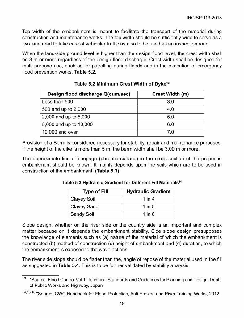
IRC:SP:113-2018
49
Top width of the embankment is meant to facilitate the transport of the material during construction and maintenance works. The top width should be sufficiently wide to serve as a two lane road to take care of vehicular traffic as also to be used as an inspection road.
When the land-side ground level is higher than the design flood level, the crest width shall be 3 m or more regardless of the design flood discharge. Crest width shall be designed for multi-purpose use, such as for patrolling during floods and in the execution of emergency flood prevention works, Table 5.2.
Table 5.2 Minimum Crest Width of Dyke13
Design flood discharge Q(cum/sec) Crest Width (m)Less than 500 3.0500 and up to 2,000 4.02,000 and up to 5,000 5.05,000 and up to 10,000 6.010,000 and over 7.0
Provision of a Berm is considered necessary for stability, repair and maintenance purposes. If the height of the dike is more than 5 m, the berm width shall be 3.00 m or more.
The approximate line of seepage (phreatic surface) in the cross-section of the proposed embankment should be known. It mainly depends upon the soils which are to be used in construction of the embankment. (Table 5.3)
Table 5.3 Hydraulic Gradient for Different Fill Materials14
Type of Fill Hydraulic GradientClayey Soil 1 in 4Clayey Sand 1 in 5Sandy Soil 1 in 6
Slope design, whether on the river side or the country side is an important and complex matter because on it depends the embankment stability. Side slope design presupposes the knowledge of elements such as (a) nature of the material of which the embankment is constructed (b) method of construction (c) height of embankment and (d) duration, to which the embankment is exposed to the wave actions
The river side slope should be flatter than the, angle of repose of the material used in the fill as suggested in Table 5.4. This is to be further validated by stability analysis.
13 *Source: Flood Control Vol 1, Technical Standards and Guidelines for Planning and Design, Deptt. of Public Works and Highway, Japan
14,15,16 *Source: CWC Handbook for Flood Protection, Anti Erosion and River Training Works, 2012.
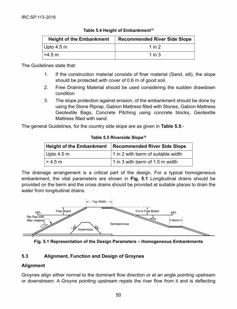
IRC:SP:113-2018
50
Table 5.4 Height of Embankment15
Height of the Embankment Recommended River side slopeUpto 4.5 m 1 in 2>4.5 m 1 in 3
The Guidelines state that:
1. If the construction material consists of finer material (Sand, silt), the slope should be protected with cover of 0.6 m of good soil.
2. Free Draining Material should be used considering the sudden drawdown condition
3. The slope protection against erosion, of the embankment should be done by using the Stone Riprap, Gabion Mattress filled with Stones, Gabion Mattress Geotextile Bags, Concrete Pitching using concrete blocks, Geotextile Mattress filled with sand.
The general Guidelines, for the country side slope are as given in Table 5.5:-
Table 5.5 Riverside slope16
Height of the Embankment Recommended River side slopeUpto 4.5 m 1 in 2 with berm of suitable width> 4.5 m 1 in 3 with berm of 1.5 m width
The drainage arrangement is a critical part of the design. For a typical homogeneous embankment, the vital parameters are shown in Fig. 5.1 Longitudinal drains should be provided on the berm and the cross drains should be provided at suitable places to drain the water from longitudinal drains.
Fig. 5.1 Representation of the Design Parameters – Homogeneous Embankments
5.3 Alignment, Function and Design of Groynes
Alignment
Groynes align either normal to the dominant flow direction or at an angle pointing upstream or downstream. A Groyne pointing upstream repels the river flow from it and is deflecting

IRC:SP:113-2018
51
Groyne. A Groyne pointing downstream attracts the river flow towards it and is attracting Groyne.
Functions of Groyne:
1. Training the river along the desired course to reduce the intensity of the flow is the main function of Groyne structure.
2. It also protects the bank by keeping the flow away from it. 3. Creating a sagging flow, this will lead to silting up of area. 4. Improving the depths for navigation purpose.Design of Groyne
Typical sections of the Groyne showing design parameters in the Nose and Shank portions is shown in Fig. 5.2 and Fig. 5.3 respectively. Geometric design of Groyne structure shall be done as per IS 8408:1994 which specifies the geometric requirements like length of Groyne, spacing of Groynes, and selection of different types of Groynes. For the Groynes constructed with flexible material/soft solutions like gabions or geotextile tubes, key length equal to 10% of length of Groyne shall be provided to enhance the stability.
Fig. 5.2 Typical section of the Groyne – Design Parameters – Nose Portion
Fig. 5.3 Typical section of the Groyne – Design Parameters – shank Portion
Filters: The use of the geosynthetic filter can be used from the point of Quality control and from construction point of view. High puncture resistance geotextile material shall be used in case of heavy stones used in the pitching.
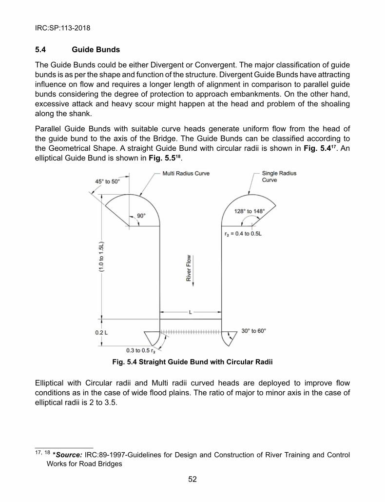
IRC:SP:113-2018
52
5.4 Guide Bunds
The Guide Bunds could be either Divergent or Convergent. The major classification of guide bunds is as per the shape and function of the structure. Divergent Guide Bunds have attracting influence on flow and requires a longer length of alignment in comparison to parallel guide bunds considering the degree of protection to approach embankments. On the other hand, excessive attack and heavy scour might happen at the head and problem of the shoaling along the shank.
Parallel Guide Bunds with suitable curve heads generate uniform flow from the head of the guide bund to the axis of the Bridge. The Guide Bunds can be classified according to the Geometrical Shape. A straight Guide Bund with circular radii is shown in Fig. 5.417. An elliptical Guide Bund is shown in Fig. 5.518.
Fig. 5.4 straight Guide Bund with Circular Radii
Elliptical with Circular radii and Multi radii curved heads are deployed to improve flow conditions as in the case of wide flood plains. The ratio of major to minor axis in the case of elliptical radii is 2 to 3.5.
17, 18 *Source: IRC:89-1997-Guidelines for Design and Construction of River Training and Control Works for Road Bridges
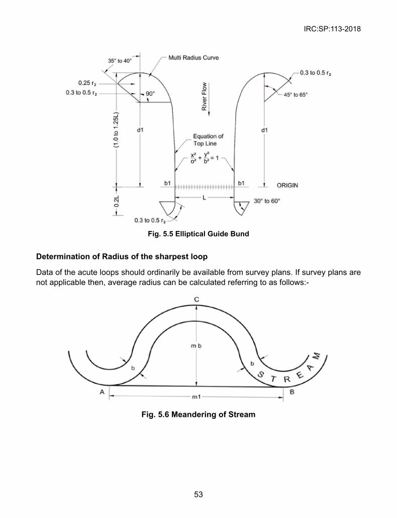
IRC:SP:113-2018
53
Fig. 5.5 Elliptical Guide Bund
Determination of Radius of the sharpest loop
Data of the acute loops should ordinarily be available from survey plans. If survey plans are not applicable then, average radius can be calculated referring to as follows:-
Fig. 5.6 Meandering of stream
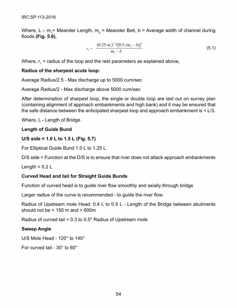
IRC:SP:113-2018
54
Where, L – m1= Meander Length, mb = Meander Belt, b = Average width of channel during floods (Fig. 5.6),
Where, r1 = radius of the loop and the rest parameters as explained above,
Radius of the sharpest acute loop:
Average Radius/2.5 - Max discharge up to 5000 cum/sec
Average Radius/2 - Max discharge above 5000 cum/sec
After determination of sharpest loop, the single or double loop are laid out on survey plan (containing alignment of approach embankments and high bank) and it may be ensured that the safe distance between the anticipated sharpest loop and approach embankment is < L/3.
Where, L - Length of Bridge.
Length of Guide Bund
U/s side = 1.0 L to 1.5 L (Fig. 5.7)
For Elliptical Guide Bund 1.0 L to 1.25 L
D/S side = Function at the D/S is to ensure that river does not attack approach embankments
Length = 0.2 L
Curved Head and tail for straight Guide Bunds
Function of curved head is to guide river flow smoothly and axially through bridge
Larger radius of the curve is recommended - to guide the river flow.
Radius of Upstream mole Head: 0.4 L to 0.5 L - Length of the Bridge between abutments should not be < 150 m and > 600m
Radius of curved tail = 0.3 to 0.5* Radius of Upstream mole
sweep Angle
U/S Mole Head - 120° to 140°
For curved tail - 30° to 60°
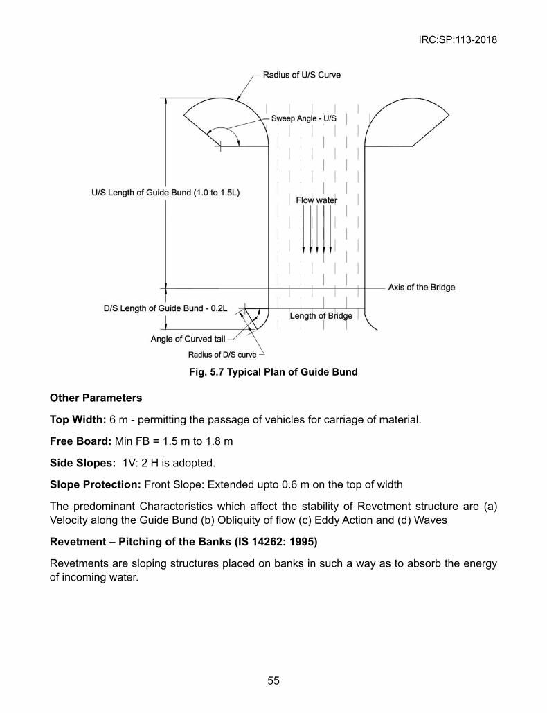
IRC:SP:113-2018
55
Fig. 5.7 Typical Plan of Guide Bund
Other Parameters
Top Width: 6 m - permitting the passage of vehicles for carriage of material.
Free Board: Min FB = 1.5 m to 1.8 m
side slopes: 1V: 2 H is adopted.
slope Protection: Front Slope: Extended upto 0.6 m on the top of width
The predominant Characteristics which affect the stability of Revetment structure are (a) Velocity along the Guide Bund (b) Obliquity of flow (c) Eddy Action and (d) Waves
Revetment – Pitching of the Banks (Is 14262: 1995)
Revetments are sloping structures placed on banks in such a way as to absorb the energy of incoming water.
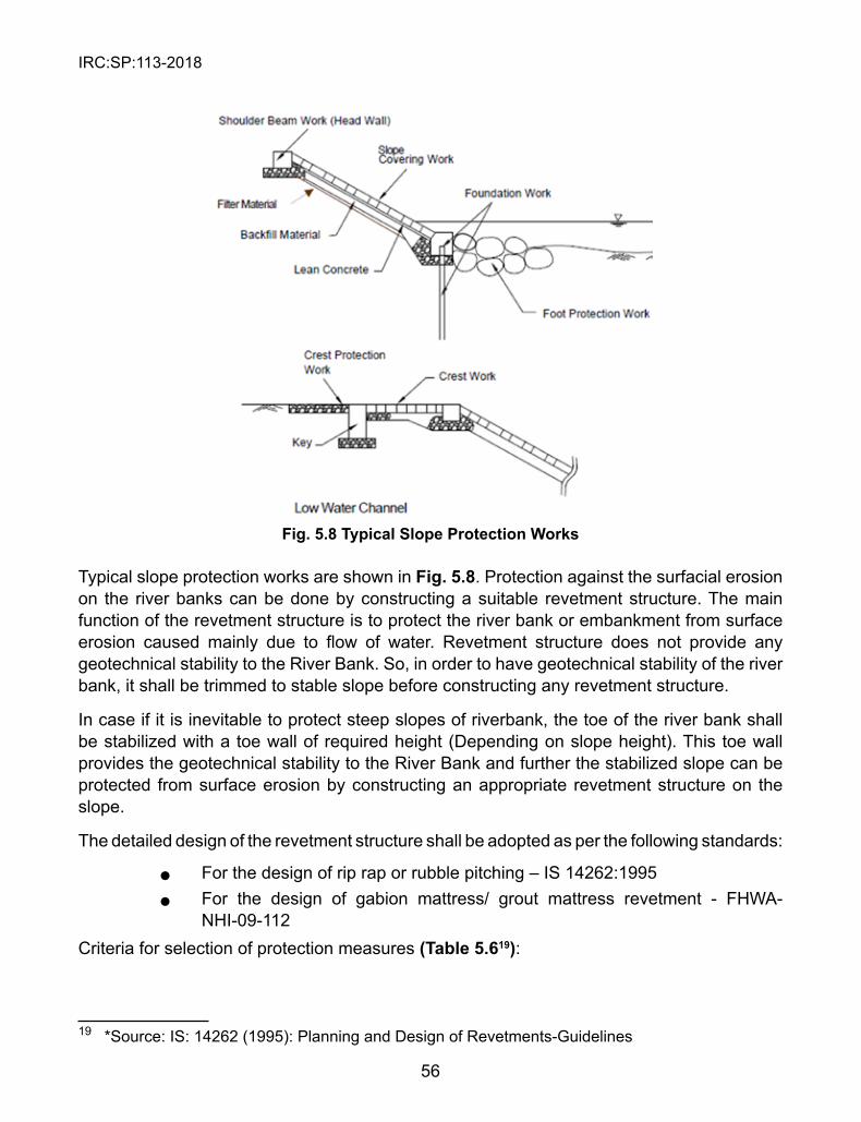
IRC:SP:113-2018
56
Fig. 5.8 Typical slope Protection Works
Typical slope protection works are shown in Fig. 5.8. Protection against the surfacial erosion on the river banks can be done by constructing a suitable revetment structure. The main function of the revetment structure is to protect the river bank or embankment from surface erosion caused mainly due to flow of water. Revetment structure does not provide any geotechnical stability to the River Bank. So, in order to have geotechnical stability of the river bank, it shall be trimmed to stable slope before constructing any revetment structure.
In case if it is inevitable to protect steep slopes of riverbank, the toe of the river bank shall be stabilized with a toe wall of required height (Depending on slope height). This toe wall provides the geotechnical stability to the River Bank and further the stabilized slope can be protected from surface erosion by constructing an appropriate revetment structure on the slope.
The detailed design of the revetment structure shall be adopted as per the following standards:
l For the design of rip rap or rubble pitching – IS 14262:1995 l For the design of gabion mattress/ grout mattress revetment - FHWA-
NHI-09-112Criteria for selection of protection measures (Table 5.619):
19 *Source: IS: 14262 (1995): Planning and Design of Revetments-Guidelines
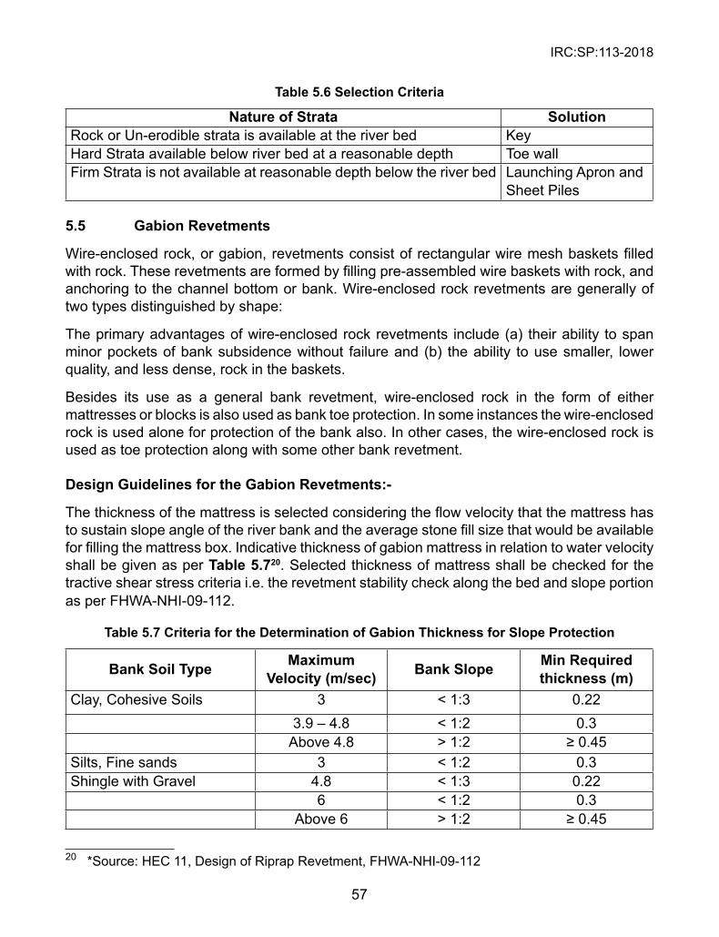
IRC:SP:113-2018
57
Table 5.6 selection Criteria
Nature of strata solutionRock or Un-erodible strata is available at the river bed KeyHard Strata available below river bed at a reasonable depth Toe wallFirm Strata is not available at reasonable depth below the river bed Launching Apron and
Sheet Piles
5.5 Gabion Revetments
Wire-enclosed rock, or gabion, revetments consist of rectangular wire mesh baskets filled with rock. These revetments are formed by filling pre-assembled wire baskets with rock, and anchoring to the channel bottom or bank. Wire-enclosed rock revetments are generally of two types distinguished by shape:
The primary advantages of wire-enclosed rock revetments include (a) their ability to span minor pockets of bank subsidence without failure and (b) the ability to use smaller, lower quality, and less dense, rock in the baskets.
Besides its use as a general bank revetment, wire-enclosed rock in the form of either mattresses or blocks is also used as bank toe protection. In some instances the wire-enclosed rock is used alone for protection of the bank also. In other cases, the wire-enclosed rock is used as toe protection along with some other bank revetment.
Design Guidelines for the Gabion Revetments:-
The thickness of the mattress is selected considering the flow velocity that the mattress has to sustain slope angle of the river bank and the average stone fill size that would be available for filling the mattress box. Indicative thickness of gabion mattress in relation to water velocity shall be given as per Table 5.720. Selected thickness of mattress shall be checked for the tractive shear stress criteria i.e. the revetment stability check along the bed and slope portion as per FHWA-NHI-09-112.
Table 5.7 Criteria for the Determination of Gabion Thickness for slope Protection
Bank soil Type Maximum Velocity (m/sec) Bank slope Min Required
thickness (m)Clay, Cohesive Soils 3 < 1:3 0.22
3.9 – 4.8 < 1:2 0.3Above 4.8 > 1:2 ≥ 0.45
Silts, Fine sands 3 < 1:2 0.3Shingle with Gravel 4.8 < 1:3 0.22
6 < 1:2 0.3Above 6 > 1:2 ≥ 0.45
20 *Source: HEC 11, Design of Riprap Revetment, FHWA-NHI-09-112
IRC:SP:113-2018
58
5.6 General Guidelines for spur Design and Construction
Spurs should not be used where the river is already narrow or where the alignment of the river banks cannot be modified or reduced. It is also not advisable to use spurs where the opposite bank is exposed to transverse flows, which create unacceptable erosion. In such cases continuous longitudinal protection is required. The effectiveness of a spur depends on its design and location, and the resources available. The location of the upstream starting point and the downstream termination point also influence the success of spur installation. The main characteristics to be considered are summarized below:
Permeability: Spurs can be permeable or impermeable. Impermeable spurs are built of local soil, stones, gravel, rocks, and gabions, while permeable spurs usually consist of one or several rows of timber, bamboo, or similar. An impermeable spur blocks and deflects the river flow, while a permeable spur allows water to pass through but reduces the water velocity.
spur Height: Spurs can be designed to be higher than the water level at all times (non-submerged), or submerged during the time of floods, emerging only when the flood recedes. In general, submerged spurs are designed to be permeable, whereas non-submerged spurs are impermeable.
The height of non-submerged spurs should not exceed the bank height because erosion at the end of the spur in the overbank area could increase the probability of outflanking when the water level (stream stage) is high. If stream stages can be greater than or equal to the bank height, the spurs should be equal to the bank height. If flood stages are always lower than the bank height, the spurs should be designed so that overtopping will not occur at the bank. Submerged spurs should have a height between 1/3 and 1/2 of the water depth.
spur Orientation relative to the River Axis: Spurs can be attracting, deflecting, or repelling according to their inclination. An attracting spur points downstream and attracts the flow towards its head and thus to the bank, maintaining a deep current close to the bank. A deflecting spur changes the direction of the flow without repelling it and creates a wake zone behind. A repelling spur points upstream and diverts the flow away from itself. The first spur in a bend should always be attracting to minimize the impact of the flow.
spur shape: Spurs are basically bar shaped, but the end protruding into the water flow can be shaped differently. An oval or elliptical spur, with the wider portion towards the bank, can change the hydraulic efficiency and reduce the direct impact of the flood water on the spur body. Investigations have shown that the shape of the spur can affect the bed stress distribution and the scour depth around a spur.
spur Length: When choosing the length of a spur, it is important to consider the safety of the opposite bank. If a spur is too long, it may guide the river current during a flash flood to the opposite bank which will cause damage; if it is too short, it may cause erosion of the near bank. As a general rule, the length of a spur should be no more than 1/5 the river width and no less than 2.5 times the scour depth. Sometimes a spur is made long and strong with the aim of changing the river course by repelling it towards the opposite bank, in which case the
IRC:SP:113-2018
59
opposite bank should also be protected. Both the river width and the width of the main flow channel to be deflected should be considered when designing the length of a spur.
The scour depth is given by R = 1.35 (q2f )1/3 (5.2)
where R = the normal scour depth below high flood level (HFL), q = discharge intensity in cum/sec per metre width, and f = Lacey’s silt factor, which depends upon the grain size of the river bed material.
The value of q can be obtained from q = Qf/Water width in m³/s/m, (5.3)
Where the water width is the flood water width in the river and Qf = 1.2Q – 1.24Q, (5.4)
where Q is the discharge.
spacing: The effect of a group of spurs depends on their length and spacing. The spacing between two spurs depends on the length of the spurs. The effect on flow is best fulfilled if one strong eddy is created between each pair of spurs. If the spacing is too wide, the effect of the spurs will be insufficient as parts of the bank will remain unaffected. A spacing less than the optimum is wasteful as it does not increase the effect. The length of bank protected by a spur is generally at least twice the length of the spur projecting perpendicular to the river water current; thus spurs do not need to be closer than twice their projecting length. In general, the spacing between two spurs should be 2–2.5 times the spur length along a concave bank and 2.5–3 times the spur length along a convex bank. In the case of a revetment with spurs, the spacing can be increased without causing harm to the bank.
Number of spurs along the stream Bank: The number of spurs depends on the length of stream bank to be protected and the calculated space between spurs.
5.7 General Guidelines for Porcupines
The use of porcupines for the flood control and anti-erosion works shall be done as per the guidelines given in Section 6 of CWC Handbook for Anti-erosion, Flood Protection and River Training Works, 2012.
IRC:SP:113-2018
60
CHAPTER 6
TECHNICAL sPECIFICATIONs
These specifications shall apply to all such road and bridge works in flood prone and flood affected areas which are required to be executed under the contract or otherwise directed by the Engineer-in charge. In this chapter, specifications of most widely used conventional materials like riprap, rubble masonry etc. to most innovative and advanced materials like geotextile bags, geotextile tubes are included.
6.1 Specifications for Stones used in Pitching/Riprap
Stone used for riprap shall be meet the gradation requirements as specified in HEC 11(Design of Riprap Revetment) such as hard, durable, angular in shape; resistant to weathering and to water action; free from overburden, spoil, shale and organic material. Breadth as well as the thickness of a single stone shall not be less than one-third of its length. In general, rounded stone or boulders, Shale and stone with shale seams are not accepted unless authorized by special provisions. Similarly mudstones and other argillaceous weak rocks should be avoided, primarily because they tend to degrade once placed. The minimum weight of the stone shall be computed by multiplying the specific gravity (bulk-saturated-surface-dry basis) times 1,000 kg/cum.
When the riprap must withstand abrasive action from material transported by the stream, the abrasion test in the Los Angeles machine shall also be used. When the abrasion test in the Los Angeles machine is used, the stone shall have a percentage loss of not more than 45 after 500 revolutions. Each load of riprap shall be reasonably well-graded from the smallest to the maximum size specified. Stones smaller than the specified 10 percent size and spalls will not be permitted in an amount exceeding 10 percent by weight of each load.
Grouted Riprap
Where grouted riprap is shown or required, surfaces of rocks with specified gradation (Table 6.121 & 6.222) shall be cleaned and wetted and the interstices filled with cement mortar, well roded and pounded in for a minimum mortar depth of 300 mm or as otherwise detailed or required by the Designer. The mortar shall consist of one part of Portland cement to three parts well graded clean fine aggregate mixed for proper consistency.
21 *Source: The Rock Manual, CIRIA C683, 200722 *Source: The Rock Manual, CIRIA C683, 2007
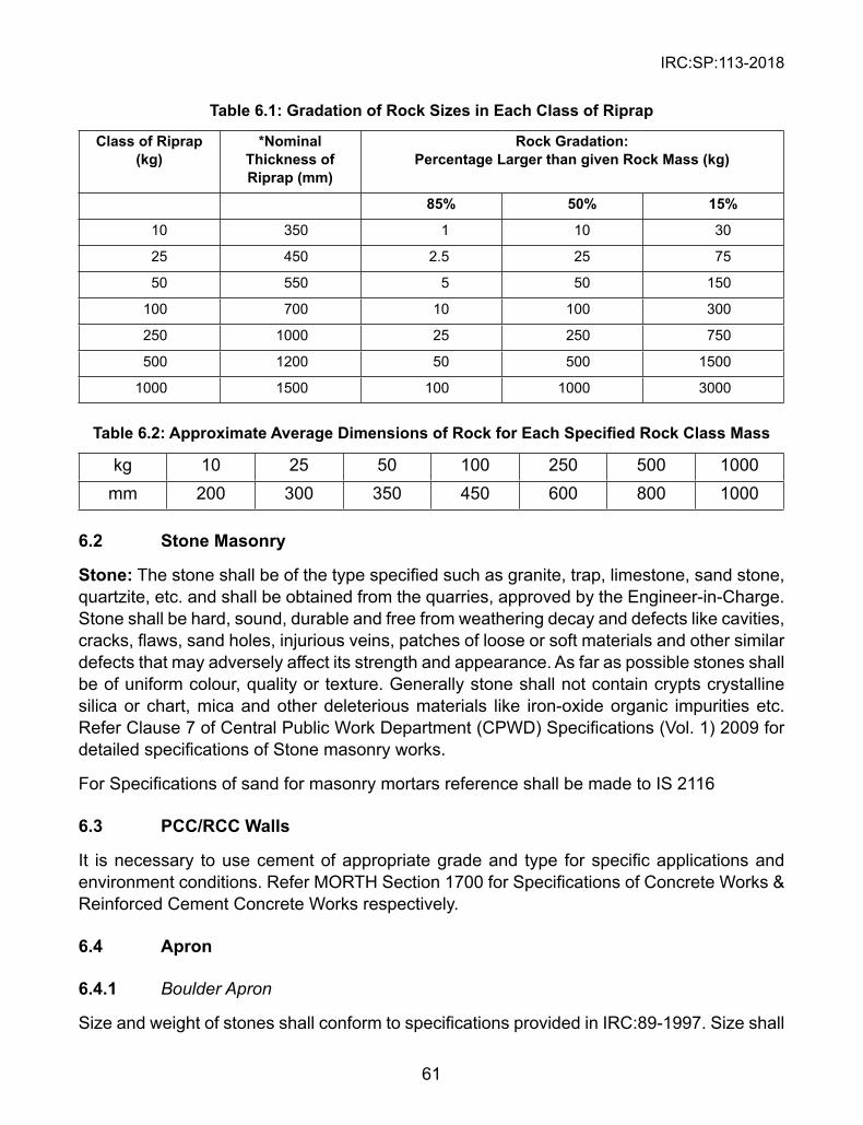
IRC:SP:113-2018
61
Table 6.1: Gradation of Rock sizes in Each Class of Riprap
Class of Riprap (kg)
*Nominal Thickness of Riprap (mm)
Rock Gradation: Percentage Larger than given Rock Mass (kg)
85% 50% 15%
10 350 1 10 30
25 450 2.5 25 75
50 550 5 50 150
100 700 10 100 300
250 1000 25 250 750
500 1200 50 500 1500
1000 1500 100 1000 3000
Table 6.2: Approximate Average Dimensions of Rock for Each Specified Rock Class Mass
kg 10 25 50 100 250 500 1000mm 200 300 350 450 600 800 1000
6.2 stone Masonry
stone: The stone shall be of the type specified such as granite, trap, limestone, sand stone, quartzite, etc. and shall be obtained from the quarries, approved by the Engineer-in-Charge. Stone shall be hard, sound, durable and free from weathering decay and defects like cavities, cracks, flaws, sand holes, injurious veins, patches of loose or soft materials and other similar defects that may adversely affect its strength and appearance. As far as possible stones shall be of uniform colour, quality or texture. Generally stone shall not contain crypts crystalline silica or chart, mica and other deleterious materials like iron-oxide organic impurities etc. Refer Clause 7 of Central Public Work Department (CPWD) Specifications (Vol. 1) 2009 for detailed specifications of Stone masonry works.
For Specifications of sand for masonry mortars reference shall be made to IS 2116
6.3 PCC/RCC Walls
It is necessary to use cement of appropriate grade and type for specific applications and environment conditions. Refer MORTH Section 1700 for Specifications of Concrete Works & Reinforced Cement Concrete Works respectively.
6.4 Apron
6.4.1 Boulder Apron
Size and weight of stones shall conform to specifications provided in IRC:89-1997. Size shall
IRC:SP:113-2018
62
be as large as possible and no stone shall weigh less than 40 kg, and specific gravity not less than 2.4. Stones used in apron shall be sound, hard, durable and fairly regular in shape. Stones subjected to marked deterioration by water or weather shall not be used. Where stones of required size are not economically available, cement concrete blocks shall be used.
6.4.2 Cement Concrete Blocks
The grade of concrete for Cement Concrete Blocks shall be minimum M15 conforming to Ministry of Road Transport & Highways (MoRTH) Specifications (Fifth Revision) Section-1700.
The types of pre-cast concrete blocks included in this specification are:
Cellular pre-cast concrete blocks. Cellular blocks which interlock with each other in some manner when placed on the embankment slope, and allow vegetation to grow through the blocks.
Concrete blocks held together by steel rods or cables and placed on the embankment slope.
Methods of tests on aggregates used for concrete shall be tested as per IS 2386 Part 1 to 8
A. Cellular Pre-cast Concrete Blocks: Concrete: The concrete shall have a minimum compressive strength 15MPa in 28 days. Cement type, aggregates, water and mixing shall conform to MoRTH Section 1700. Mixing water shall be fresh, clean, and potable. In freeze-thaw areas, air entrapment of 5-1/2% to 8-1/2% shall be provided. Water reducing admixtures and/or super-plasticizers are permitted. Anchors shall be corrosive-resistant and have provisions for attaching to the cellular mat. Filter: The cellular pre-cast concrete block revetment shall have filter blanket of gravel or fabric placed underneath the revetment. The filter shall meet the requirements given in the Guidelines. All materials shall conform to the specifications for concrete masonry in MoRTH Section 1700.
B. Articulated Pre-cast Concrete Blocks: The concrete used for fabrication of the blocks shall be Class A
Reinforcement: The wire mesh shall be attached to the bar reinforcement and the bar steel shall be in the indicated position shown on the plans. The wire mesh shall be 18 gauge wire and the bar steel shall be 13 mm diameter. The longitudinal cable or rod linking the blocks shall be 20 mm diameter steel.
Anchors: Anchors shall be corrosive-resistant and have provisions for attaching to the articulated mat.
Filter: The articulated pre-cast concrete block revetment shall have a filter blanket of gravel or plastic placed underneath the revetment.
All materials shall conform to the Specifications for Roads and Bridges Works, Ministry of Road Transport & Highways.
IRC:SP:113-2018
63
6.5 Specifications of Geotextile Materials used for Anti-erosion, River Training and Bank Protection Works
A geotextile fabric is in the form of strong flexible sheets either woven or non-woven. It is used in flood management works to improve soil quality and performance in different applications like lining, drainage, filtration, separation, reinforcement and protection.
The basic raw material which is used in geotextile is polymer and the most widely used polymers are polypropylene and polyester. Based upon the manufacturing process, geotextile is often categorized as woven or non-woven. Woven geotextiles are manufactured by weaving weft thread through warp thread. While non-woven geotextile is produced from randomly distributed continuous or staple fibers which are bonded together chemically, thermally or mechanically.
Geotextile fabrics are used with specific strength and durability requirements as per the proposed work. The detailed technical specifications of the geotextiles along with the test methods and their recommended values for each parameter are being described in the following paragraphs in detail:
6.5.1 Geotextile Filter:
The material should be woven with multifilament yarn in both warp and weft direction or non-woven needle punched type with staple fiber network. The geotextile shall be made of polypropylene/polyester with 100% virgin polymer. No recycled polymers shall be used in manufacturing of geotextiles. The specifications of geotextile filter shall confirm to Section 700 of MORTH Clause 702.
6.6 Specifications for Geotextile Bags
Geotextile bags are made of woven/non-woven polypropylene/polyester geotextile material;. Double layer geotextile bags using woven (tape by tape) and non-woven geotextile are used for harsh conditions. Geotextile used to manufacture the geotextile bags should have high mechanical and hydraulic properties for enhanced durability along with enhanced puncture, abrasion and U.V. resistance characteristics. Geotextile should be inert to biological degradation and resistant to naturally encountered chemicals, alkalis, and acids.
6.6.1 Requirements for a Sustainable and Performing Geosynthetic Bag System:
l Adequate weight to sustain the uplift pressure due to Hydraulic Forces l High Abrasion Resistance l Adequate Puncture Strength l High Elongation to absorb the Hydraulic Energy
IRC:SP:113-2018
64
l Lower Apparent Opening size to retain even the finer soil particles l High Permittivity and Transmissivity l Adequate UV Resistance l Stable in wider pH range
6.6.2 Important Considerations in Specifying the Right Geotextile Bags System:
l Type of Polymer: PP and PET are the commonly used Polymers for these works, however through successive field experience PP is found to have better performance in case of high alkaline conditions. Therefore, it is always advisable to specify on PP for Geotextile bags in alkaline conditions.
l Quality of Polymer Fiber: The virgin fibers with more than 70 % UV resistance shall be used as raw material for making the Fabric and Geotextile bags, no recycled fiber shall be allowed for making of Geotextile bags.
l Type of Fiber: Staple Fiber is much better and found to have superior performance for River bank and Coastal application compared to Continuous Fibers which degrades when comes in contact with water.
l There are several bonding mechanisms available; however the appropriate for river application is Needle Punching.
l Important Properties for performance of Geotextile Bags are- UV Resistance, CBR Puncture, Tensile Strength, Seam strength, Apparent Opening size and Permeability.
Geotextile used to manufacture Geotextile bags made of non-woven material may conform to the properties listed in following Table 6.4. The Specifications for Composite Geotextile Bags to be used in harsh conditions are specified in Table 6.5.
6.6.3 Requirements
6.6.3.1 Material of Geotextile bags
a. Geotextile bags shall be made from needle punched nonwoven fabric (Types 1 to 3) and composite bags shall be made of woven (tape by tape) and non-woven fabric manufactured from ultra violet stabilized Polyester or Polypropylene and constituent fibre shall be identified by the microscopic and confirmatory tests as specified in IS 667; depending upon the end user requirements and shall conform to the requirements as specified in Table 6.3. The geotextile bags shall be inert to commonly encountered chemicals, resistant to rot and mildew, and shall have no tears or defects which adversely affect or alter its physical properties.
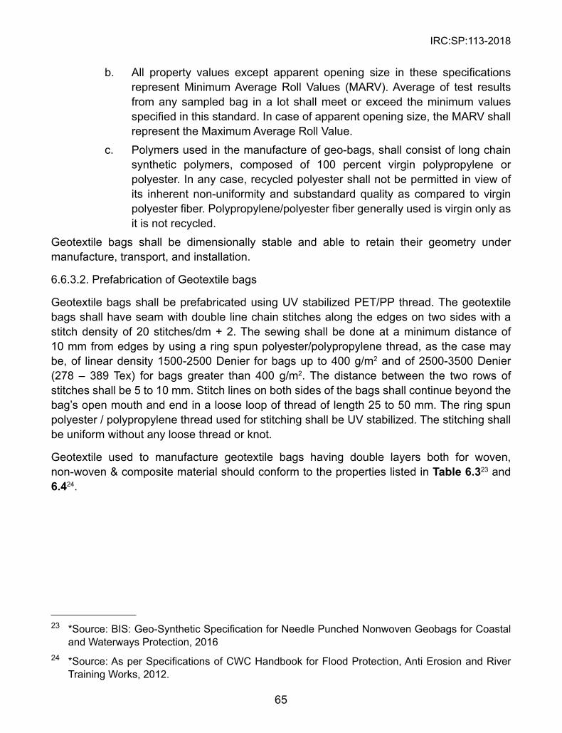
IRC:SP:113-2018
65
b. All property values except apparent opening size in these specifications represent Minimum Average Roll Values (MARV). Average of test results from any sampled bag in a lot shall meet or exceed the minimum values specified in this standard. In case of apparent opening size, the MARV shall represent the Maximum Average Roll Value.
c. Polymers used in the manufacture of geo-bags, shall consist of long chain synthetic polymers, composed of 100 percent virgin polypropylene or polyester. In any case, recycled polyester shall not be permitted in view of its inherent non-uniformity and substandard quality as compared to virgin polyester fiber. Polypropylene/polyester fiber generally used is virgin only as it is not recycled.
Geotextile bags shall be dimensionally stable and able to retain their geometry under manufacture, transport, and installation.
6.6.3.2. Prefabrication of Geotextile bags
Geotextile bags shall be prefabricated using UV stabilized PET/PP thread. The geotextile bags shall have seam with double line chain stitches along the edges on two sides with a stitch density of 20 stitches/dm + 2. The sewing shall be done at a minimum distance of 10 mm from edges by using a ring spun polyester/polypropylene thread, as the case may be, of linear density 1500-2500 Denier for bags up to 400 g/m2 and of 2500-3500 Denier (278 – 389 Tex) for bags greater than 400 g/m2. The distance between the two rows of stitches shall be 5 to 10 mm. Stitch lines on both sides of the bags shall continue beyond the bag’s open mouth and end in a loose loop of thread of length 25 to 50 mm. The ring spun polyester / polypropylene thread used for stitching shall be UV stabilized. The stitching shall be uniform without any loose thread or knot.
Geotextile used to manufacture geotextile bags having double layers both for woven, non-woven & composite material should conform to the properties listed in Table 6.323 and 6.424.
23 *Source: BIS: Geo-Synthetic Specification for Needle Punched Nonwoven Geobags for Coastal and Waterways Protection, 2016
24 *Source: As per Specifications of CWC Handbook for Flood Protection, Anti Erosion and River Training Works, 2012.
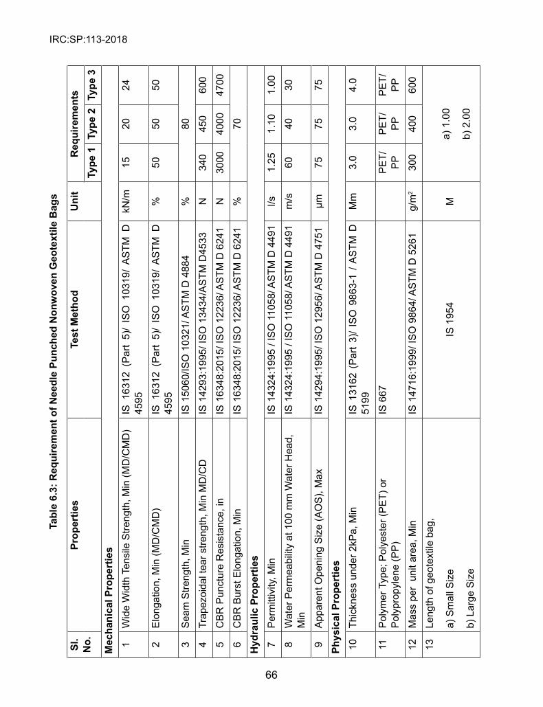
IRC:SP:113-2018
66
Tabl
e 6.
3: R
equi
rem
ent o
f Nee
dle
Punc
hed
Non
wov
en G
eote
xtile
Bag
s
sl.
No.
Prop
ertie
sTe
st M
etho
dU
nit
Req
uire
men
tsTy
pe 1
Type
2Ty
pe 3
Mec
hani
cal P
rope
rtie
s1
Wid
e W
idth
Ten
sile
Stre
ngth
, Min
(MD
/CM
D)
IS 1
6312
(P
art
5)/
ISO
103
19/
AS
TM D
45
95kN
/m15
2024
2E
long
atio
n, M
in (M
D/C
MD
)IS
163
12 (
Par
t 5)
/ IS
O 1
0319
/ A
STM
D
4595
%50
5050
3S
eam
Stre
ngth
, Min
IS 1
5060
/ISO
103
21/ A
STM
D 4
884
%80
4Tr
apez
oida
l tea
r stre
ngth
, Min
MD
/CD
IS 1
4293
:199
5/ IS
O 1
3434
/AS
TM D
4533
N34
045
060
0
5C
BR
Pun
ctur
e R
esis
tanc
e, in
IS 1
6348
:201
5/ IS
O 1
2236
/ AS
TM D
624
1N
3000
4000
4700
6C
BR
Bur
st E
long
atio
n, M
inIS
163
48:2
015/
ISO
122
36/ A
STM
D 6
241
%70
Hyd
raul
ic P
rope
rtie
s7
Per
mitt
ivity
, Min
IS 1
4324
:199
5 / I
SO
110
58/ A
STM
D 4
491
l/s1.
251.
101.
00
8W
ater
Per
mea
bilit
y at
100
mm
Wat
er H
ead,
M
inIS
143
24:1
995
/ IS
O 1
1058
/ AS
TM D
449
1m
/s60
4030
9A
ppar
ent O
peni
ng S
ize
(AO
S),
Max
IS 1
4294
:199
5/ IS
O 1
2956
/ AS
TM D
475
1µm
7575
75
Phys
ical
Pro
pert
ies
10Th
ickn
ess
unde
r 2kP
a, M
inIS
131
62 (
Par
t 3)
/ IS
O 9
863-
1 / A
STM
D
5199
Mm
3.0
3.0
4.0
11P
olym
er T
ype;
Pol
yest
er (P
ET)
or
Pol
ypro
pyle
ne (P
P)
IS 6
67P
ET/
PP
PE
T/P
PP
ET/
PP
12M
ass
per
unit
area
, Min
IS 1
4716
:199
9/ IS
O 9
864/
AS
TM D
526
1g/
m2
300
400
600
13Le
ngth
of g
eote
xtile
bag
,
a) S
mal
l Siz
e
b) L
arge
Siz
e
IS 1
954
M
a) 1
.00
b) 2
.00

IRC:SP:113-2018
67
14W
idth
of g
eote
xtile
bag
,
a) S
mal
l Siz
e
b) L
arge
Siz
e
IS 1
954
Ma)
0.7
0
b) 1
.50
15W
eigh
t of fi
lled
geot
extil
e ba
g, M
in
a) S
mal
l Siz
e B
ag
b) L
arge
Siz
e B
ag
Ele
ctro
nic
Wei
ghin
g B
alan
ceK
ga)
126
b) 1
350
16D
urab
ility
Sha
ll be
dur
able
for
a
min
imum
of
10 y
ears
in
natu
ral s
oil w
ith 4
≤pH
≤9
and
soil
tem
pera
ture
be
twee
n -2
0o C to
25o C
.
17U
V R
esis
tanc
e af
ter 5
00 h
exp
osur
e, M
inA
STM
D 4
355
%70
7070

IRC:SP:113-2018
68
Table 6.4: Properties of Composite Geotextile Bags
Properties Reference for Test Method Unit ValuesNon-
WovenWoven (Tape)
Properties of GeotextilePolymer Type PP PP
Mass per unit area IS 14716:1999/ ISO 9864/ ASTM D 5261
gsm ≥140 ≥210
Wide Width Tensile Strength IS 16312 (Part 5)/ ISO 10319/ ASTM D 4595
kN/m ≥9 ≥40
Wide Width Tensile Elongation IS 16312 (Part 5)/ ISO 10319/ ASTM D 4595
% ≥50 ≤25
Trapezoidal Tear Strength IS 14293:1995/ ISO 13434/ASTM D4533
N ≥200 ≥500
Puncture Resistance IS 16348:2015/ ISO 12236/ ASTM D 6241
N ≥300 ≥500
Apparent Opening Size IS 14294:1995/ ISO 12956/ ASTM D 4751
mm ≤0.212 ≤0.42
UV Resistance ASTM D4355 %/hrs 70/500 70/500
Properties of Geotextile Bag
Seam Type Double Seam
Preferably flat dimensions 2.00m x 1.50m
Note: Lay Flat dimensions of the Geotextile Bags given above are preferable sizes. The Client is free to use site specific sizes less than specified values but shall not exceed the dimensions given in Tables 6.3 and 6.4
6.7 Specifications of Geotextile Tubes
All the Geotextile Tubes shall be new and undamaged. Materials which are not new and damaged will be not be accepted. These shall be as per the manufacturers design drawings for a particular application.
l Material shall have no environmental impact such as pollution or leaching. l The company providing the material must demonstrate the geotextile
products that have been used and proven in past for onshore/offshore/ near shore applications whichever is applicable.
l The company must have proven ability to manufacture required shape of Geotextile Tube.
The Geotextile tubes shall be fabricated with standard sheets of high strength Geotextile Material to form a tubular shape as specified by the designer. The Woven Geotextile shall be

IRC:SP:113-2018
69
made of multifilament Polyester/ Polypropylene fibres.
The dimensions of finished Geotextile Tube shall be as per the requirements of designer and supplier fabricating capacity. The Geotextile Tube shall be fabricated in such a way to ensure efficient and durable containment system suitable for riverine or coastal applications.
The geotextile tubes should be constructed to meet the specifications (dimensions, type of materials and properties) mentioned in GRI GT 10: Test Methods, Properties and Frequencies for High Strength Geotextile Tubes used as Coastal and Riverine Structures.
6.8 Specifications for Geocomposite Multi Cellular Structure
Geocomposite Multi-cellular structure is made of hexagonal double twisted wire mesh 10x12 or 8x10 type (8x10 type Mesh properties as per IS 16014 and Section 2500 of MoRTH).The mesh is reinforced with vertical steel rods and internally lined with a geotextile sleeve (Fig. 6.1). section 6.9 shows the characteristics of the double twisted steel woven wire mesh.
The reinforcing steel rods inserted into the double twist (Fig. 6.2) during the manufacturing process shall have a spacing of one mesh length (approx. 162 mm).The rods shall have minimum diameter of 4.9 mm, they are made of the same steel of the mesh and each one is folded both at the top and bottom ends.
The geotextile is a nonwoven with a minimum weight of 250 g/m2. It forms an internal lining for each cell; each lining is overlapped and attached to the top edge of the unit, while the lower part of the fabric is left loose to be folded internally on site to form a soil retention seal. Galvanic staples are used to fasten the geotextile to the mesh panels to hold it in place.
Fig. 6.1 Multi Cellular structure of Geotextile and Wire Mesh
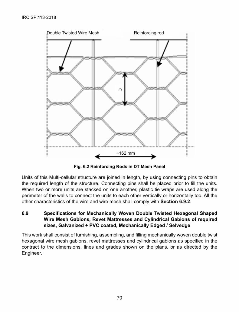
IRC:SP:113-2018
70
Fig. 6.2 Reinforcing Rods in DT Mesh Panel
Double Twisted Wire Mesh Reinforcing rod
~162 mm
D
Units of this Multi-cellular structure are joined in length, by using connecting pins to obtain the required length of the structure. Connecting pins shall be placed prior to fill the units. When two or more units are stacked on one another, plastic tie wraps are used along the perimeter of the walls to connect the units to each other vertically or horizontally too. All the other characteristics of the wire and wire mesh shall comply with section 6.9.2.
6.9 Specifications for Mechanically Woven Double Twisted Hexagonal Shaped Wire Mesh Gabions, Revet Mattresses and Cylindrical Gabions of required sizes, Galvanized + PVC coated, Mechanically Edged / selvedge
This work shall consist of furnishing, assembling, and filling mechanically woven double twist hexagonal wire mesh gabions, revet mattresses and cylindrical gabions as specified in the contract to the dimensions, lines and grades shown on the plans, or as directed by the Engineer.
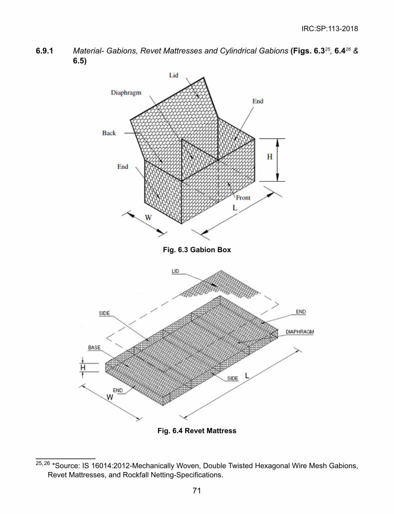
IRC:SP:113-2018
71
6.9.1 Material- Gabions, Revet Mattresses and Cylindrical Gabions (Figs. 6.325, 6.426 & 6.5)
Fig. 6.3 Gabion Box
Fig. 6.4 Revet Mattress
25, 26 *Source: IS 16014:2012-Mechanically Woven, Double Twisted Hexagonal Wire Mesh Gabions, Revet Mattresses, and Rockfall Netting-Specifications.
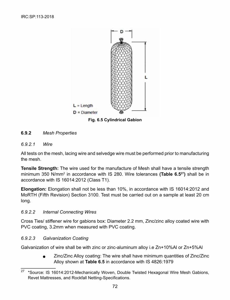
IRC:SP:113-2018
72
Fig. 6.5 Cylindrical Gabion
6.9.2 Mesh Properties
6.9.2.1 Wire
All tests on the mesh, lacing wire and selvedge wire must be performed prior to manufacturing the mesh.
Tensile strength: The wire used for the manufacture of Mesh shall have a tensile strength minimum 350 N/mm2 in accordance with IS 280. Wire tolerances (Table 6.527) shall be in accordance with IS 16014:2012 (Class T1).
Elongation: Elongation shall not be less than 10%, in accordance with IS 16014:2012 and MoRTH (Fifth Revision) Section 3100. Test must be carried out on a sample at least 20 cm long.
6.9.2.2 Internal Connecting Wires
Cross Ties/ stiffener wire for gabions box: Diameter 2.2 mm, Zinc/zinc alloy coated wire with PVC coating, 3.2mm when measured with PVC coating.
6.9.2.3 Galvanization Coating
Galvanization of wire shall be with zinc or zinc-aluminum alloy i.e Zn+10%Al or Zn+5%Al
l Zinc/Zinc Alloy coating: The wire shall have minimum quantities of Zinc/Zinc Alloy shown at Table 6.5 in accordance with IS 4826:1979
27 *Source: IS 16014:2012-Mechanically Woven, Double Twisted Hexagonal Wire Mesh Gabions, Revet Mattresses, and Rockfall Netting-Specifications.
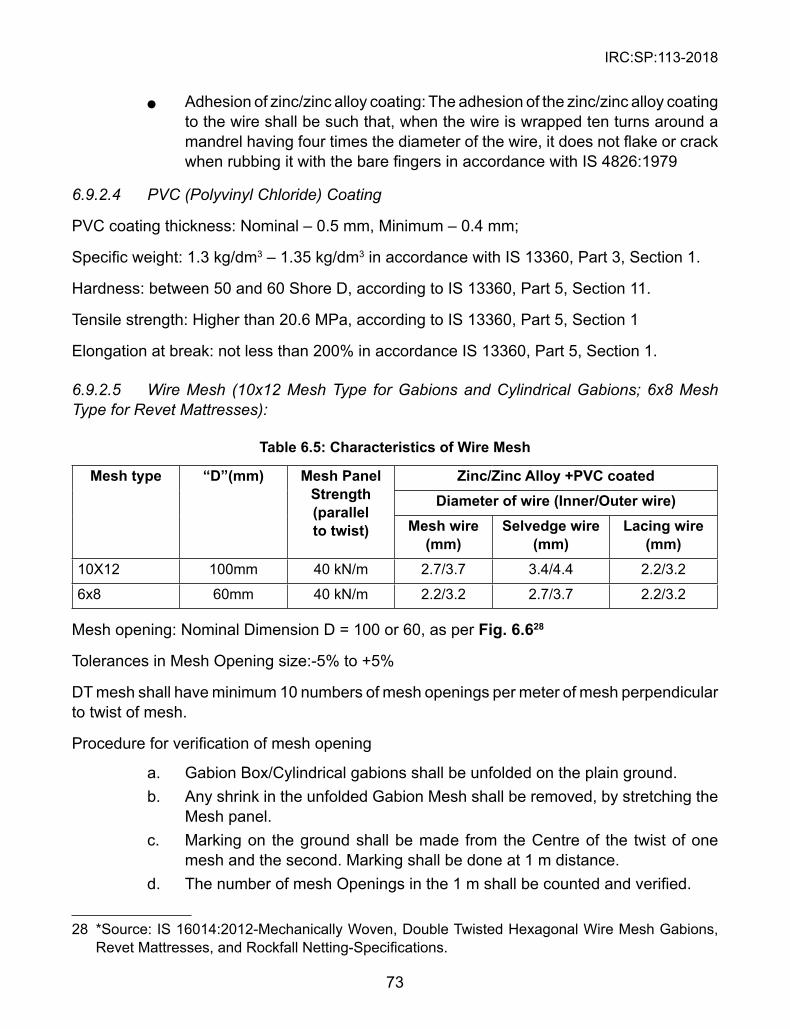
IRC:SP:113-2018
73
l Adhesion of zinc/zinc alloy coating: The adhesion of the zinc/zinc alloy coating to the wire shall be such that, when the wire is wrapped ten turns around a mandrel having four times the diameter of the wire, it does not flake or crack when rubbing it with the bare fingers in accordance with IS 4826:1979
6.9.2.4 PVC (Polyvinyl Chloride) Coating
PVC coating thickness: Nominal – 0.5 mm, Minimum – 0.4 mm;
Specific weight: 1.3 kg/dm3 – 1.35 kg/dm3 in accordance with IS 13360, Part 3, Section 1.
Hardness: between 50 and 60 Shore D, according to IS 13360, Part 5, Section 11.
Tensile strength: Higher than 20.6 MPa, according to IS 13360, Part 5, Section 1
Elongation at break: not less than 200% in accordance IS 13360, Part 5, Section 1.
6.9.2.5 Wire Mesh (10x12 Mesh Type for Gabions and Cylindrical Gabions; 6x8 Mesh Type for Revet Mattresses):
Table 6.5: Characteristics of Wire Mesh
Mesh type “D”(mm) Mesh Panel strength (parallel to twist)
Zinc/Zinc Alloy +PVC coatedDiameter of wire (Inner/Outer wire)
Mesh wire (mm)
selvedge wire (mm)
Lacing wire (mm)
10X12 100mm 40 kN/m 2.7/3.7 3.4/4.4 2.2/3.2
6x8 60mm 40 kN/m 2.2/3.2 2.7/3.7 2.2/3.2
Mesh opening: Nominal Dimension D = 100 or 60, as per Fig. 6.628
Tolerances in Mesh Opening size:-5% to +5%
DT mesh shall have minimum 10 numbers of mesh openings per meter of mesh perpendicular to twist of mesh.
Procedure for verification of mesh opening
a. Gabion Box/Cylindrical gabions shall be unfolded on the plain ground. b. Any shrink in the unfolded Gabion Mesh shall be removed, by stretching the
Mesh panel. c. Marking on the ground shall be made from the Centre of the twist of one
mesh and the second. Marking shall be done at 1 m distance. d. The number of mesh Openings in the 1 m shall be counted and verified.
28 *Source: IS 16014:2012-Mechanically Woven, Double Twisted Hexagonal Wire Mesh Gabions, Revet Mattresses, and Rockfall Netting-Specifications.
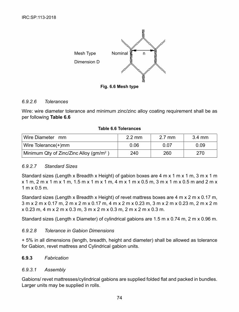
IRC:SP:113-2018
74
Fig. 6.6 Mesh type
6.9.2.6 Tolerances
Wire: wire diameter tolerance and minimum zinc/zinc alloy coating requirement shall be as per following Table 6.6
Table 6.6 Tolerances
Wire Diameter mm 2.2 mm 2.7 mm 3.4 mmWire Tolerance(+)mm 0.06 0.07 0.09Minimum Qty of Zinc/Zinc Alloy (gm/m2 ) 240 260 270
6.9.2.7 Standard Sizes
Standard sizes (Length x Breadth x Height) of gabion boxes are 4 m x 1 m x 1 m, 3 m x 1 m x 1 m, 2 m x 1 m x 1 m, 1.5 m x 1 m x 1 m, 4 m x 1 m x 0.5 m, 3 m x 1 m x 0.5 m and 2 m x 1 m x 0.5 m.
Standard sizes (Length x Breadth x Height) of revet mattress boxes are 4 m x 2 m x 0.17 m, 3 m x 2 m x 0.17 m, 2 m x 2 m x 0.17 m, 4 m x 2 m x 0.23 m, 3 m x 2 m x 0.23 m, 2 m x 2 m x 0.23 m, 4 m x 2 m x 0.3 m, 3 m x 2 m x 0.3 m, 2 m x 2 m x 0.3 m.
Standard sizes (Length x Diameter) of cylindrical gabions are 1.5 m x 0.74 m, 2 m x 0.96 m.
6.9.2.8 Tolerance in Gabion Dimensions
+ 5% in all dimensions (length, breadth, height and diameter) shall be allowed as tolerance for Gabion, revet mattress and Cylindrical gabion units.
6.9.3 Fabrication
6.9.3.1 Assembly
Gabions/ revet mattresses/cylindrical gabions are supplied folded flat and packed in bundles. Larger units may be supplied in rolls.
Mesh Type
Dimension D
Nominal n
IRC:SP:113-2018
75
The gabion or revet mattress box units are assembled individually by erecting the sides, ends, and diaphragms, ensuring that all panels are in the correct position, and the tops of all sides are satisfactorily aligned. The four corners of gabion units shall be connected first, followed by the internal diaphragms to the outside walls.
The mesh forming cylindrical gabion shall be unfolded from packed bundles. The mesh shall be rolled to form a cylindrical shape containment unit. One end of the DT wire mesh cylindrical gabion shall be tied / closed by pulling the shooting bar.
The procedure for using lacing wire consists of cutting a sufficient length of wire, and first looping and/or twisting the lacing wire to the wire mesh. Proceed to lace with alternating double and single loops through every mesh opening, pulling each loop tight and finally securing the end of the lacing wire to the wire mesh by looping and/or twisting. Refer Fig. 6.729
Fig. 6.7 Lacing wire
6.9.3.2 Installation
After initial assembly, the gabion boxes are carried to their final position and are securely joined together along the vertical and top edges of their contact surfaces using the same connecting procedure(s) described earlier. Whenever a structure requires more than one layer, the upper empty baskets shall also be connected to the top of the lower layer along the front and back edges of the contact surface using the same connecting procedure(s) described in section 6.9.3.1.
29 *Source: IS 16014:2012-Mechanically Woven, Double Twisted Hexagonal Wire Mesh Gabions, Revet Mattresses, and Rockfall Netting-Specifications.
IRC:SP:113-2018
76
Installation of cylindrical gabion filling at site should be strictly as per the instruction or approved by Engineer aligned with manufacturer’s instructions as per the site specific requirements
6.9.3.3 Testing and Acceptance Criteria
The material should get approval from the client before the actual supply start. The manufacturer of the Gabion/revet mattress/cylindrical gabions should provide “Manufacturers Test Certificate’ for the material with every lot/shipment.
Tensile strength test and zinc/Zinc Alloy coating test on basic wire shall be done on one sample per every 10,000 numbers of units supplied.
PVC Coating Thickness: The thickness of the PVC coating shall be determined on a randomly chosen individual piece of wire removed from the coil at 3 places 1 m apart. Measure with a micrometer the diameter of the galvanized steel wire with PVC coating. Determine the thickness of the PVC coating by stripping the PVC coating from the wire and measure the reduced diameter with a micrometer. The thickness of the coating is the difference between the diameter of the galvanized steel wire with PVC coating and the measured diameter of the galvanized steel wire divided by two. The thickness values should be as per Clause 6.9.2.4. While removing the PVC coating by stripping, take care not to remove any of the metallic surfaces. The punch strength test results shall be 19kN in accordance with MoRTH section 2500 and test specified therein.
6.9.3.4 Tensile Strength Test Procedure for Wire Mesh
The tensile strength test on wire mesh shall be carried as per procedure outlined in IS 16014:2012.
6.9.3.5 Selvedge Strength Test
A tensile test on mesh sample shall be carried out in order to estimate selvedge strength test. The test shall be carried out as per procedure outlined below. The selvedge strength shall be minimum 25 kN/m for 10x12 mesh type and 10.2 kN/m for 6x8 mesh type.
a) Take a DT mesh of approximately 1.0 m width. b) The height of the sample shall be such that after selvedging on both the
sides (1m), there shall be at least two mesh repetitions between the two selvedged wires, so that effective height of the sample shall be more than 300 mm.
c) Sample shall be loaded on the UTM in a direction parallel to twist, with the samples being gripped at the two selvedged wires and not mesh twist.
d) The distance between the two selvedge wires shall be recorded as Initial gauge length.

IRC:SP:113-2018
77
e) Distance between the two end gripping points (pins) along the width of the sample shall be recorded as the unit width under test. The width shall be at least 700 mm.
f) The load shall be applied gradually to the sample and the test be continued till the break point.
g) The peak load and the % elongation shall be recorded. h) The strength of the selvedge connection shall be (peak load/unit width under
test) expressed in kN/m.If the sample slips at any of the gripping point during the test, such a test shall be discarded and a new sample shall be taken.
IRC:SP:113-2018
78
CHAPTER 7
INsTALLATION AND CONsTRUCTION
7.1 Introduction
The construction, planning for works envisaged in any flood management/river training works is a vital component for the timely completion of the works avoiding time and cost overrun. Time is of essence of flood management works as the same has to be completed in available non-monsoon season. Construction methodology includes proper construction of the works as per the approved design and drawings. This also includes the in-time procurement, mobilization and proper installation of the construction materials being used for the works. The installation procedure for the innovative materials like Geo-Textile Bags, Geo-Mattress, Geo-Textile tubes etc should be performed in a systematic controlled and well planned manner so that it would give optimum benefits due to use of these materials.
This practice provides guidelines for the installation of different systems explained in this guideline. This practice, however, is not to be considered as all-encompassing since each material and site specific condition usually presents its own challenges and special issues. Site or project specific conditions may require them to be altered to ensure effective installation under the guidance of the engineer and/or manufacturer.
7.2 Bank Protection Works/ slope Covering Works
7.2.1 Bank Preparation
As per the guidelines of “HEC 11 – Design of Riprap Revetment, FHWA”, the bank should be prepared by first clearing all trees and debris from the bank and grading the bank surface to the desired slope. The area shall be prepared by excavating, shaping and trimming to accommodate the stone work and shall be thoroughly compacted by hand-ramming to minimize subsequent settlement. A trench shall be excavated as directed by the Engineer along the toe of any slope to be pitched or along the unprotected edge of the pitching in the beds of stream.
In general, the graded surface should not deviate from the specified slope line by more than 150 mm. However, local depressions larger than this can be accommodated because initial placement of filter material and/or rock for the revetment will fill these depressions. In addition, any large boulders or debris found buried near the edges of the revetment should be removed.
7.2.2 Riprap/Stone Pitching
As per the guidelines of “HEC 11 – Design of Riprap Revetment, FHWA”, the common methods of riprap placement are hand placing; machine placing, such as from a skip, dragline or some form of bucket; and dumping from trucks and spreading by bulldozer. Hand placement
IRC:SP:113-2018
79
produces the best riprap revetment, but it is an expensive method. Steeper side slopes can be used with hand-placed riprap than with other placing methods.
Where steep slopes are unavoidable (where channel widths are constricted by existing bridge openings or other structures, and where acquiring right-of-way is costly), hand placement should be considered.
In the machine-placement method, sufficiently small increments of stone should be released as close to their final positions as practical. Re-handling or dragging operations to smooth the revetment surface tend to result in segregation and breakage of stone and can result in a rough revetment surface.
Stone should not be dropped from an excessive height since this may result in the same undesirable conditions. Riprap placement by dumping with spreading is satisfactory provided that the required layer thickness is achieved. Riprap placement by dumping and spreading is the least desirable method as a large amount of segregation and breakage can occur and is not recommended. In some cases, it may be economical to increase the layer thickness and stone size somewhat to offset the shortcomings of this placement method.
Commencing at the bottom of the trench, the stone shall be laid and firmly bedded into the slope and against adjoining stones. The stones shall be laid with their longitudinal axes at right angles to the slope and with their surfaces in contact so as to break joint. The stones shall be well rammed into the bank or surface to be protected and the spaces between the larger stones shall be filled with fragments of approved pitching stone securely rammed into place. Placing of rock by dumping shall not be allowed.
The finished surface of the pitching shall present an even, tight and neat appearance with no stones varying by more than 25 mm from specified surface grades or lines. The thickness of the pitching, measured at right angles to the surface, shall not be less than 200 mm, or as indicated on the drawings.
7.2.3 Gabions/ Revet Mattresses
Construction details for rock and wire mattresses vary with the design and purpose for which the protection is provided.
Rock and wire mattress revetments may be fabricated where they are to be placed or at an off-site location. Fabrication at an off-site location requires that the individual mattress units be transported to the site. In this case, extreme care must be taken so that moving and placing the mattresses does not damage them by breaking or loosening strands of wire or ties or by removing any of the galvanizing or PVC coating.
The following sequence shall be followed in construction of Gabions:
l Excavate the formation to the required level as shown in the drawings. If good bearing stratum is not observed after the excavation up to mentioned levels then, the same should be brought to the notice of Engineer-in-Charge for
IRC:SP:113-2018
80
further advice. The surface of formation should be free from any deleterious material and unwanted foreign objects. Loose pockets if any, should be excavated and filled with suitable granular or backfill material.
l Roll the formation using Vibro-roller of 8 to 10 tonnes capacity in case the width is available for roller movement. The design requirements with respect to bearing capacity should be achieved and verified before proceeding further. Density of compacted formation should be greater than or equal to 95% of the modified Proctor value.
l The formation prepared should be leveled without ruts and undulations. l The outer alignment of the fascia should be marked by the survey team as
per the requirements in the section and plan drawings. l The non-woven geotextile shall be laid out below. (Only if specified in
drawings) l The folded gabion unit shall now be opened by placing it on a flat surface
or leveled ground and straightening out the various end panels. One or two persons may be deployed for the straightening of DT mesh panel activity depending on the size of gabions.
l The back, front, end panels along with the diaphragms shall now be folded along the lines after verifying the required correct dimension of the base from the section drawings. The diaphragm is secured in position to the base so that no additional lacing is necessary at the site.
l The gabion box shall then be assembled by making the end panels on either side meet with the front and back panels. The upper corners at each of the pair of side panels shall now be tied with the lacing wire. The diaphragm panel used for creating the cells within the gabion shall also be tied to the front and back panels.
l The lower side of the gabion edges and of the existing diaphragms shall then be sewn from bottom to top by the lacing procedure.
l The procedure for using lacing wire consists of cutting a sufficient length of wire, and first looping and/or twisting to secure the lacing wire to the wire mesh. Proceed to lace with alternating double and single loops through every mesh opening approximately every 150 mm pulling each loop tight and finally securing the end of the lacing wire to the wire mesh by looping and /or twisting..
l Adequate care shall be taken during the lacing operation to ensure that the base panel of gabion measures the inner dimension required in the section drawings. While ensuring the base dimension, proper arrangements shall be done to ensure that the side panels form a right angle with the base and the gabion box achieves a proper geometry. For this purpose, a right angle corner template arrangement made from Wood/Mild steel/Aluminum section shall be used.
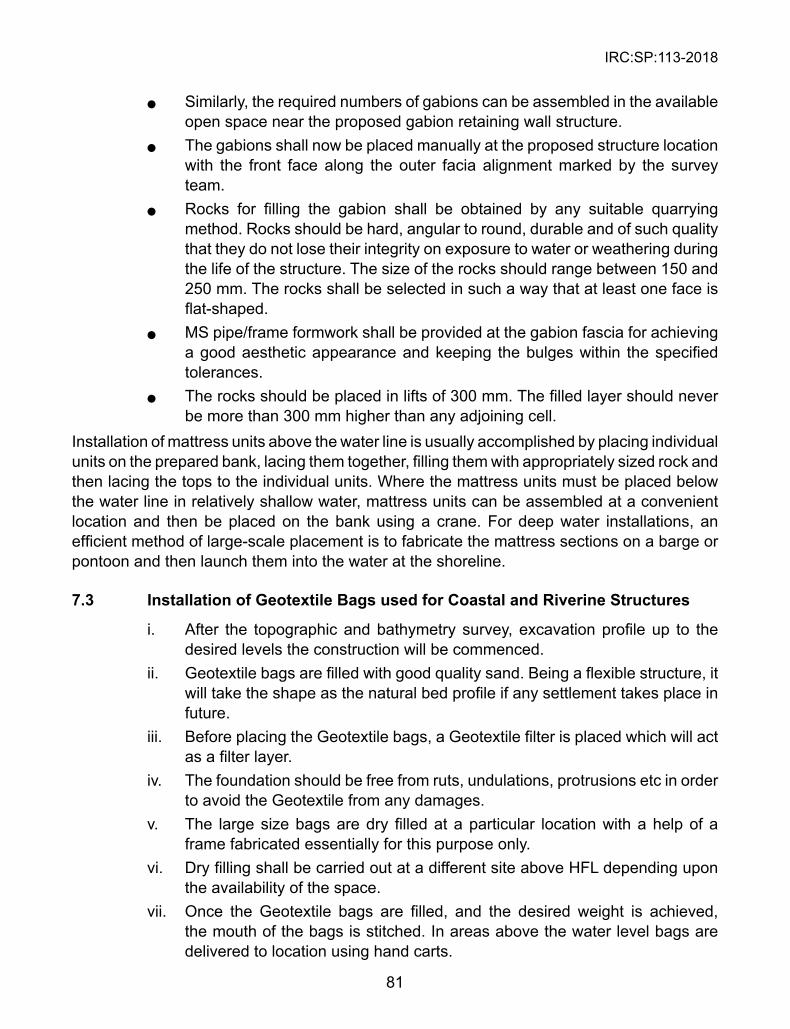
IRC:SP:113-2018
81
l Similarly, the required numbers of gabions can be assembled in the available open space near the proposed gabion retaining wall structure.
l The gabions shall now be placed manually at the proposed structure location with the front face along the outer facia alignment marked by the survey team.
l Rocks for filling the gabion shall be obtained by any suitable quarrying method. Rocks should be hard, angular to round, durable and of such quality that they do not lose their integrity on exposure to water or weathering during the life of the structure. The size of the rocks should range between 150 and 250 mm. The rocks shall be selected in such a way that at least one face is flat-shaped.
l MS pipe/frame formwork shall be provided at the gabion fascia for achieving a good aesthetic appearance and keeping the bulges within the specified tolerances.
l The rocks should be placed in lifts of 300 mm. The filled layer should never be more than 300 mm higher than any adjoining cell.
Installation of mattress units above the water line is usually accomplished by placing individual units on the prepared bank, lacing them together, filling them with appropriately sized rock and then lacing the tops to the individual units. Where the mattress units must be placed below the water line in relatively shallow water, mattress units can be assembled at a convenient location and then be placed on the bank using a crane. For deep water installations, an efficient method of large-scale placement is to fabricate the mattress sections on a barge or pontoon and then launch them into the water at the shoreline.
7.3 Installation of Geotextile Bags used for Coastal and Riverine structures
i. After the topographic and bathymetry survey, excavation profile up to the desired levels the construction will be commenced.
ii. Geotextile bags are filled with good quality sand. Being a flexible structure, it will take the shape as the natural bed profile if any settlement takes place in future.
iii. Before placing the Geotextile bags, a Geotextile filter is placed which will act as a filter layer.
iv. The foundation should be free from ruts, undulations, protrusions etc in order to avoid the Geotextile from any damages.
v. The large size bags are dry filled at a particular location with a help of a frame fabricated essentially for this purpose only.
vi. Dry filling shall be carried out at a different site above HFL depending upon the availability of the space.
vii. Once the Geotextile bags are filled, and the desired weight is achieved, the mouth of the bags is stitched. In areas above the water level bags are delivered to location using hand carts.

IRC:SP:113-2018
82
viii. Prefilled Large Size bags are then placed onto the site with the help of crane and slings attached to place these properly.
ix. Special care should be taken while dumping the Large Size bags into the water so that it would not damage the material.
x. Checking of the installed Geotextile Bags shall be carried out and confirmed that the bags are placed in desired locations.
7.4 Installation of Geotextile Tubes used for Coastal and Riverine structures
The installation of Geotextile tubes shall be carried out as per the installation procedure of GRI GT 11: Standard Practice for Installation of Geotextile Tubes used for Coastal and Riverine Structures.
7.5 Installation and Preparation of Cylindrical Gabion Containment system
DT wire mesh cylindrical gabions shall be supplied folded flat and packed in bundles. Larger units may be supplied in rolls and the liner bags for these larger units are supplied separately.
The units are assembled individually in a manner to accommodate the containment system. The mesh forming cylindrical gabion and the geotextile containment system shall be unfolded from packed bundles. The mesh shall be rolled to form a composite cylindrical shape containment unit.
One end of the DT wire mesh cylindrical gabion shall be tied/closed by pulling the shooting bar. The Geotextile containment shall be supplied with top end open for filling of the sand and the bag shall be stitched with a portable stitching machine post filling the containment unit with the sand or appropriate fill materials.
The bundles of Cylindrical Gabions shall be brought to the construction site from the project store and stacked in similar fashion as was done at the project stores.
These bundles shall be stacked on a leveled ground with wooden rafters/sleepers in between them for easy handling and preventing any damage to the DT mesh and other components like the selvedge wire.
The bundles may be opened at the storage yard for supplying the exact quantity of cylindrical gabions to the construction site. The individual folded cylindrical gabion units shall be handled properly as shown to avoid any damage to the DT mesh and other components.
Post Filling Installation
Once the filling is completed, the filled containment system should be neatly stored together and kept in a specified location. The containment system would have minimum weight of approximately around 700-850 kgs when filled, depending upon the type of fill material used. Care should be taken that these containment systems are not dragged or pulled along the ground. For apron construction, the filled containment systems are loaded on a boat/vessel
IRC:SP:113-2018
83
and then dumped into desired location. The lifting of these containment systems is carried out by help of cranes.
For units near the bank portion, can be placed in position with the help of the cranes. Care should be taken that there should not be any damage to the containment units.
Construction sequence
The sequence of activities that should be followed to carry out the works is given below:
1. The material once reaching the site shall be stacked and stored properly in dry areas and handled with care in order to minimize the damage to the procured items.
2. The location of material storage and the area identified for filling operation should be located in nearby area.
3. The area for filling operations must be clean and free from organic matter. The area should have minimum undulations in order to transport the filled containment units to the feeder units easily.
4. The sand available in the sand stock pile should be free from organic matter. 5. The filling operations shall be carried out with due care. The selection of the
filling method will be based on actual site conditions. 6. Once filled, the bags will be lifted with the help of Hydra cranes and stacked
appropriately in the stacking yard. The stacking yard should be maintained dry and free from burrow animals as a protection measure for the containment units.
7. The filled containment units will then transported to the loading area and then transported to areas where dumping is to be carried out.
8. Small boats to be used to inspect the area post placing or dumping of the containment units.
7.6 Multi Cellular Geocomposite Flood Containment Units can be easily installed according to the following instructions
1. Remove each unit from the pallet; lift and unfold the unit by pulling it straight and twisting the end corners.
2. Join adjacent units in length to form a continuous wall by using connecting pins. They will be inserted through the spirals of adjacent unit corners.
3. Fold the bottom of the fabric liner inside each cell to form a soil retention seal during the filling.
4. Fill the unit with material available on site, such as soil, rocks, bricks, gravel, etc. Each unit shall be filled uniformly. Filling shall begin from central units preferably.
IRC:SP:113-2018
84
CHAPTER 8
MAINTENANCE AND MONITORING OF FLOOD MITIGATION sYsTEM
8.1 General
Flood control works as designed and constructed are expected to remain both safe and functional throughout their service lives. It is, therefore, imperative that the efficacy of the flood control works is periodically and conscientiously monitored, assessed and re-evaluated for timely preventive/ corrective action. This chapter outlines activities that are essential to protect and maintain flood control works for which an Operation and Maintenance Manual (OMM) should be prepared based on region specific body of knowledge and collective wisdom. Information on allocation of responsibilities; identification of anticipated flood threats; catalogues of flood hazard maps and documented past flood records; stipulation of instrumentation, monitoring and inspection schedules; unambiguous directions on emergency planning, crisis management and reporting; directory of domain experts, institutions, designers, contractors; suppliers and disaster managers must all be amenable for quick retrieval when needed. Study of and reference to the Guidelines of Flood Mitigation Works-Operation and Maintenance Manual, 2001 of Ministry of Environment, British Columbia is recommended towards evolving region specific OMM tuned to the ground realities.
8.2 Inspection of Flood Embankments
Routine Annual Inspection
The importance of routine annual inspection for assessment of the performance of Flood Control Works is essential for timely alert and prompt remedial action. The best time to schedule an annual inspection would be prior to the flood season during the pre-monsoon period. That would allow sufficient time to understand and address maintenance problems in the offing. In the event of any adverse assessment reports on the performance of any of the flood control works, it is important to quickly follow the matter further by commissioning an in-depth investigation by a multi-disciplinary emergency management team, for stitch in time.
The annual inspection report must provide critical observations, and analysis of all visual and pictorial evidences related to the structural and non-structural components of flood control works. An experienced inspector, or a team of inspectors, should be quick enough to observe the dike behaviour in terms of (a) deformation profile of the dike in general and emergence of low and high spots along the dike crest (b) slope failure, subsidence and consequent damage to the dike slopes (c) bursting of river banks and the associated evidences of bank erosion (d) unauthorized excavation, construction and eco-vandalism (e)erosion leading to scour of the riverbank protection and (f) debris and other problems at intakes. If and when doubt about safety of any flood protection dike raised in the routine inspection report, recourse should be taken to a detailed inspection to answer the questions raised in the report. If need
IRC:SP:113-2018
85
be, aerial and underwater surveys for investigation and mapping of damages may also be undertaken.
The observations such as (a) the spread of vegetation growth and behaviour of trees (b) animal burrows (c) the condition of all fences, gates and locks and the availability of keys and (d) damage to water level gauges, etc., may help in the ensuing planning for preventive and remedial action.
8.3 Inspections during High Water Events
In the age of Information Communication Technology, continuous and real-time monitoring of flood protection works, especially in the areas of high hazard is rapidly becoming a matter of routine. The techniques of remote sensing coupled with drone surveys have transformed the ways patrolling and inspections are carried out by the multi-disciplinary teams, especially in the areas of high hazard. The frequency and timings of patrolling and inspections can now be guided and modulated by analysis of observational data using modern technology.Wherever inspection reports raises doubts and the integrity of flood protection works is suspect, in-depth investigation, additional dike inspections and more frequent patrolling should be carried out to ensure timely corrective action. During high water events, local water level gauges should be monitored regularly and the readings recorded should be analyzed in the light of the previous and historic data. Dike patrol frequency should increase as the water levels approach critical conditions, and should be continuous while the level is within 1.0 m of the dike crest.
The content, quality and speed of reporting must receive careful attention so that inspection reports not only raise right questions at the right time but also provide enough insights to facilitate quick decision making. It is, therefore, necessary to ensure that the inspection team has the ability to distinguish between normal and abnormal behaviour. It should not only trained in the art of observations but should also be fully aware of what is expected of the flood control works and what all could go wrong during the high water events. For instance, during the high water events, when flood levels are high, it is quite normal to observe enhanced seepage appearing at landward toe of the dike. On the other hand, sudden emergence of water streams, evidences of erosion, scouring and piping, subsidence and sloughing of dike crest and slopes, locations of low free, accumulations of debris at flood boxes, flap gates and trash racks and board bursting of banks are sure indicators of an impending disaster.
A constant watch is necessary on calibration and reliable functioning of all monitoring instruments. Pumps must not malfunction when they are needed the most. Cables and pipes when inspected must not point to seepage along them. Mapping of surface and subsurface cracks and their subsequent propagation can throw light on the performance behaviour of dikes.
8.4 Post Flood Inspections and Evaluations
The post flood inspection must always be by a multi-disciplinary team so that the interplay of causative factors could be understood to the last detail and lessons from failures could
IRC:SP:113-2018
86
be learned for forward planning and remediation. Mapping and assessment of flood inflicted damages should be undertaken immediately after water levels have subsided. It is also important to correlate the observations with the causative factors and experiences gained during similar events in the past. During the inspection, areas requiring action should be categorized as vital, essential and desirable so that the priorities are not lost. Many of the field evidences recorded and inferences made during the inspection will serve as invaluable inputs to the design of remedial packages and therefore independent validation of all major observations is essential. Efforts should be made to locate and record a complete high water profile along the dike after significant flow events. This information is useful in assessing the dike crest level and the freeboard.
Post flood inspections related to cyclonic storms and tsunamis are matters requiring much higher levels of expertise and fall outside the scope of these Guidelines.
8.5 Dike Maintenance/Repair
It is important to develop a check list of items of inspection and Do’s and Don’ts. First and foremost, the flood protection works including all fences should be promptly attended to ensure timely minor repair work. The locks of the gates should always be kept functional and their keys should be easily accessible to the authorized personnel at any time of day and night. Effort should be made to insulate flood protection works from possible eco-vandalism. One way would be to seek restricted access for unauthorized vehicles, another way would be to enhance patrolling. The profile of the dike crest should be periodically retrieved by addition of crushed gravel surfacing, as required to maintain a reasonably smooth and competent driving surface. Vegetation on the dike fill side slopes should consist of closely trimmed grass or low ground cover. Depending on local growth rates, dike slopes should be trimmed and restored at least once in a year. Trees and brush growth should not be allowed, if detrimental to safety of dikes. The environmental approvals should become an essential feature of the guidelines for dike maintenance. Animal holes or burrows in fills should be suitably dealt with by backfilling/grouting.
Damage to dike slopes should be repaired and the slope should be restored as soon as possible by the addition and compaction of appropriate clean earth fill materials. Water level gauges and monitoring devices should be periodically inspected, repaired and re-leveled, if necessary. It is important that inspection personnel do not miss them out.
8.6 Bank Protection Maintenance and Repair
The nature of remedial action required for bank protection will depend on the level of maintenance and repair required in a given case. In routine maintenance, use riprap or gabion mattress over a geotextile filter is usually enough for bank protection. The design for rock gradation or mattress thickness is determined as per the guidelines given in Chapter 6. The bank protection will require varying maintenance depending upon the extent, level and duration of flooding, frequency and level of exposure to stream flooding, wave action and floating debris. Repair to damaged pitching is commonly made by replacing the

IRC:SP:113-2018
87
damaged portion with a new material. Riprap or gabion mattress shall be prefilled and using the crane arrangement, the damaged portion shall be replaced. If a major damage or failure of bank protection occurs, professional engineering advice must be sought and necessary approvals obtained.
8.7 Flood Box Maintenance
When the external water level turns lower than the water level behind the dike, it will be subject to higher thrust of water for which it may not be designed. It is for this reason, to balance out thrust of water on the dyke, it is common to provide flood boxes. All the flood boxes do is to allow gravity transfer of water from behind the dike into the main water course. A typical flood box consists of a conduit or culvert passing through the dike with a flap gate at the outlet on the water side. It may also have trash racks at both ends to keep debris out.
For efficient functioning of flood boxes, their periodic cleaning and maintenance is essential. Unless both inlet and outlet are cleaned of debris and silt, flow of water will be impaired. Similarly, unless the flip gates are cleaned and lubricated to make sure that they swing freely and close properly, they will not function when needed the most. Unwanted growth of vegetation and trees close to flood boxes often hamper inspection and maintenance. Furthermore, the culvert pipes, if made of metal should be checked for corrosion and blockage. Culverts whether made of metal or concrete would have to be inspected internally for leakage at joints, loss of joint sealant and unacceptable deformation levels, especially at joints.
IRC:SP:113-2018
88
CHAPTER 9
CONCLUsIONs, RECOMMENDATIONs AND THE WAY FORWARD
9.1 Policy Framework
The engineering of Highways and Roads in the flood-prone areas of India should be firmly anchored to the over-arching provisions of the National Disaster Management Act of 2005 and the National Policy on Disaster Management of 2009. The National Platform on Disaster Risk Reduction; the Sendai Framework; the Johannesburg Plan30 and the India’s National Disaster Management Plan31 all resonate with India’s notified national policy, and aim at achieve Sustainable Development through Disaster Mitigation and Mitigation. In the light of the above, it is obligatory that highway engineers (a)mainstream flood disaster mitigation into the process of highway planning , design and construction, (b) promote culture of prevention, preparedness and resilience against flood disasters in a multi-hazard context,(c) encourage implementation of environment friendly mitigation measures using time-tested technology and traditional wisdom, (d)ensure efficient mechanism for identification, assessment , monitoring of disaster risks and for early warning , and (e) recognize every project of reconstruction as an opportunity to build back better. It is imperative that the DPR of all major road projects must necessarily conform to the broad policy framework outlined above.
In keeping with the first priority of the Sandai Frame work- Understanding risk in a multi-hazard environment- to which India stands committed; all major highway and road engineering projects should begin with assessment of all tenable hazard scenarios and risk, in multi-hazard context. Earlier too, the Hyogo Framework of Action (2005-15) had also laid considerable emphasis on an integrated multi-hazard approach to risk reduction. Naturally, flood disasters cannot and should not be looked at in isolation while planning, designing, constructing and protecting highways and roads. Rather, all schemes of flood safe designs, prevention, protection and remediation should be driven by the multi-hazard disaster risk resilience approach. For example, a flood safe embankment located in a seismic area must necessarily be seismic safe or a flood safe highway in a hilly area must necessarily be landslide safe.
9.2 Recommendations
Flood Hazard and Risk Management
1. Credible Flood hazard and inundation mapping hold the key to understanding of the flood hazard in a specific situation. Development of scientifically
30 Evolved at the World Submit on Sustainable Development held during 26 August - 4 September, 2002
31 Released in June, 2016
IRC:SP:113-2018
89
credible, and user-friendly, large scale flood hazard zonation and inundation mapping must therefore be accorded the highest priority at all levels. Space technologies Landsat-TM and SPOT images and the potential of Landsat-TM and SPOT images should be fully tapped to prepare large scale flood hazard maps and to study hydro-geology and drainage characteristics of related catchments. It is equally essential to obtain comprehensive and large scale coverage of flood affected infrastructure for risk analysis and updating of maps facilitated by Earth Observation Satellite data and high resolution images.
2. Forecasting of floods, timely projection of site specific flood scenarios and their periodic revalidation should become a routine practice. It is only then that the volume, veracity, velocity and variety of big data on extreme weather events and flood prone areas will benefit planning, design, construction and protection of highways and roads.
3. Lessons learned from the previous flood disasters in an area should be ploughed back in evolving flood-safe design of roads in that area. For instance, reconstruction of a stretch of road or a bridge destroyed by a flood or a flood-induced landslide should rule out similar occurrences in that area, in future. In other words, it should be possible to instantly recall and effectively use information on the previous flood events, for forward planning, design and construction.
4. Systematic documentation of real time flood hazard and inundation, video-filming, damage assessment and monitoring of the progress of rescue, relief and remedial works should be made mandatory in crisis times.
5. The power of new technology such as Remote controlled and Programmed Drones-should be effectively used for pre and post disaster investigations, surveys of flood prone areas, delivery of supplies, reaching out to inaccessible areas and for providing surveillance. Unmanned Aerial Vehicles or Drones and Hot Air Balloons are finding sensational applications in flood disaster management and India can immensely benefit from their effective use.
9.3 Planning, Design and Construction
1. Planning, design and construction of highways and roads in flood prone areas should take in to account geo-morphology and hydro-geology of the area, long range rainfall records and extreme weather events, catchment characteristics, drainage patterns, over-land and subsurface flows and the existing negative impacts of ill-planned urbanization on drainage.
2. All major projects should take steps to ensure that highways and roads themselves do not become cause of flooding, or aggravate flooding by obstructing natural drainage routes. This is perhaps the single most important lesson learned from the study of major flood disasters across the country, including the Chennai floods of 2005 and 2015. By the same logic, risk due
IRC:SP:113-2018
90
to flooding can be minimised32 by removing obstructions, clearing drainage routes and improving the drainage of the area.
3. Utmost attention must be paid to alignment of roads. For instance, major floods often result from faulty alignment of roads in hilly areas because of the frequent choking of water streams and rivers by landslide debris and bursting of landslide dams they create resulting in flash floods. These very Riverine floods then destroy bridges downstream and trigger more landslides. Every DPR should therefore closely examine the various competitive options before decision making. Expenditure in selection of most eco-friendly and technically sound road alignment should be considered as the best investment strategy, especially if roads traverse through a hazardous geo-environment.
4. Critical engineering scrutiny of road designs and the contingency flood management plans is also essential, wherever the road-alignment foul river regimes, especially in the areas of high flood hazard. This is all the more important because at the planning, design and construction stages, it is often difficult to fully account for uncertainties arising from unknown unknowns, known unknowns and shaky design assumptions. The failures of embankments along the banks of river Koshi during the Bihar floods of 2007 were precisely because the unknown consequences of the known trend of the shifting river course. It was because of this that the embankments on the river banks were subjected to an enormous amount of lateral thrust for which the embankments had not been designed.
5. Planning of the road network should be such that it provides alternative routes of connectivity for effective post flood evacuation, rescue and relief distribution. The NDMA Report of 28 September 2017 on Tamil Nadu floods favours formation of green corridors in vulnerable areas to facilitate rapid movement of rescue teams.
6. Designs of embankments must be safe not only against subsidence, slope and base failures but the designs must also rule out flood induced liquefaction, scouring and erosion. When embankments are designed exclusively for flood protection, their designs should be integrated with the designs of other related flood control measures such as storage dams and detention basins.
7. In the design of highways and roads along and across water courses in river basins, safety against flooding can be achieved only if the design takes into account the interdependence of, and interaction between the individual flood mitigation and flood control measures.
32 This way the reason that, well in advance of the North East Monsoon flood season of 2016, a comprehensive programme of cleaning of drains, culverts and preventive maintenance of drainage facilities was undertaken in Chennai. Encroachments and blockages on either side of 15870 bridges and more than 1.4 lakh culverts and were removed, 500 m upstream and downstream, and at least 5000 culverts were cleaned.
IRC:SP:113-2018
91
8. Functional disaster knowledge networks and multi-institutional co-operation at all levels of government are essential for effective implementation of sectoral policies regarding environmental protection, physical planning, land use planning, agriculture, road transport and urban development.
9. All major ongoing highway constructions which are at risk of flooding should be critically reviewed without loss of time to ensure safety against all the anticipated flood scenarios. When facing damages due to floods, the softer option of taking recourse to palliative measures and quick-fix solutions must give way to holistic remediation.
10. Flood protection is never absolute; even then a high level of protection against flooding can be reached through timely intervention. Project authorities should always remain alert to the residual risk for each flood control structure. In each case, the consequence analysis should be made in consonance with the design level of protection beyond which the flood control defences may give way.
11. If the present trends are any indicator, urban areas in India are rapidly expanding and the associated network is becoming much more vulnerable to urban flooding. Since the highway engineering planning, design and construction practices have not improved fast enough to match the growing vulnerability of roads to urban floods, it is essential that the present Acts related to Town planning, Industrial zone planning, Land reforms and Transportation corridors should be expeditiously reviewed and suitably amended. Preservation of water bodies, efficient disposal of urban wastes, total ban on encroachments, revamping of existing drainage systems, augmentation of surface and subsurface drainage all need exceptional attention.
9.4 Use of smart Construction Materials
For flood resilient construction of roads, inter alia, smart construction materials and technologies hold considerable promise. The global market is full of smart materials and technologies for improving the drainage of highways and roads, and countering flooding. Since little is known about long term performance of newly introduced smart construction materials and technologies, their selection to meet site-specific requirement should be done with utmost caution and adequate preparedness to meet the contingencies.
In urban areas, flooding is very common because of impervious road surfaces, paved foot paths, ill-planned urban infrastructure and clogged storm water drains. Smart materials such as Top-mix Permeable concrete33 has brought a new hope in flood safe highway designs as it can absorb 880 gallons of water in one minute to counter inundation effect and make driveways, pavements, walkways and parking areas flood-safe . In the patented process, the Topmix Permeable is applied over a base layer of gravel and the flood water is allowed to
33 Lafarge Tarmac, manufacturer of Topmix Permeable
IRC:SP:113-2018
92
either permeate into the ground below or is diverted elsewhere, over a period of time, through a series of pipes. Similarly holistic drainage solutions making efficient use of different variants of Geo-synthetics can significantly reduce flood proneness of urban areas by augmenting drainage.
Central and State Governments should launch projects aimed at upgrading, supplementing or replacing non-functional Storm Water Drainage Systems by promoting large scale applications of smart materials and technologies.
9.5 Mitigation and Management
For implementation of flood risk resilience measures in a given highway project, care should be taken to ensure that (a) technology used is not only be cost and speed effective but it is also eco-friendly (b) synergy of measures is fully tapped and (c) question of sustainability is adequately addressed.
Floods in rivers often destroy roads and bridges. Over topping and scouring of bridge piers are among the main causes of bridge failures. We need technologies to inspect and track scouring of bridge foundations in real time for timely corrective action. Physical inspection of the foundations of such bridges, especially if unsafe, is neither feasible nor a good idea. Highway engineers in the USA have already developed technologies which can facilitate condition monitoring of pier foundations threatened by scouring. Also, automated instrumentation systems mounted on driverless vehicles hold promise for relatively risk free condition monitoring of bridges and robot managed repair work in cases where access is risky.
Intelligent Transportation Systems34, well tested telecommunication and Vehicular Ad hoc Networks (VANETs) are finding increasing demand in flood disaster management. By introducing community based traffic applications, the drivers are now able to share real time data on traffic flow, road accidents, flooding related information, and locate the nearest safe parking. Also, by field instrumentation and monitoring of floods and stitch in time, it is now possible to pro-actively ensure the safety of evacuation roads and routes, and maintain access to police and fire stations and hospitals in the times of crisis. The concept of Intelligent Streets promises emergency alerts, digital warnings, display of evacuation routes and recording of rising water level by lamp-posts. In the event of unacceptable levels of flooding, public transportation system will be automatically shut. In the event of road accidents and flood trapped vehicles, there will be no need to call police or ambulance as the vehicle itself will do the reporting.
Management of potholed-roads to reduce flood risks is of critical importance. Every year dozens of people die because of the visible as well as water covered pot holes in the flooded
34 Intelligent River Information Systems are already benefiting National Waterway 1 on River Ganges; Farakka to Patna-Phase 2 and Patna to Varanasi-Phase 3. The IRIS should be integrated with flood-disaster risk reduction strategies.
IRC:SP:113-2018
93
roads. It is high time we think of innovative solutions deploying smart, easy to implement and possibly self healing technologies capable of quick repair of roads and road infra-structure. Self-healing technologies also hold considerable Promise.35
9.6 Flood Protection Works
There are a number of different possible options in terms of products and technologies for protection of highways and roads against flooding. For example, use of Geosynthethics/ Geotextiles, gabions etc. are quite common. Real progress will be made when we begin to document failure case records which are in reality the true teachers. It is quite understandable that flourishing businesses thrive on success stories and usually shy away from talking about failure case records for the fear of adverse publicity. Both Failure and Success-stories based on long-term scientific monitoring and well analyzed feedback needs to be encouraged.
9.7 standardization
The advocacy for standardisation is the need of the hour. This should include all aspects including flood hazard mapping, risk assessment, site investigations and flood disaster mitigation.
Standardization of commonly used materials for flood protection works is also highly desirable. Take for example, standardization for testing of Geosynthethics. Reportedly the BIS, ASTM, ISO and others show fair degree of convergence in thinking. There are hardly any SOPs for evaluating the efficacy of the protection works as a whole.
The culture of Observational Method of Design and Construction in Geotechnical treatment of Highway engineering problems needs encouragement. We design protection works under the veil of uncertainties by making assumptions which are seldom questioned. We make use of empirical approaches to design without meditating on their applicability or otherwise, and the ensuing consequences. There is no built-in mechanism to scientifically evaluate our designs with the passage of time. Many of the designers do not even realize that sometimes, remedies could be worse than the respective maladies, if the composite behaviour of the protection works get judged only in terms of the strengths of its individual components. Geotechnically well established approaches to stability analyses in terms of total and effective stress to rule out vital modes of failure are also seen to be generally out of the current practice.
The consideration of aesthetics and environment friendly appearance in design of flood protection works should also receive utmost attention. For example, massive rock emplacements for coastal road protection provide bad optics as eye-sores and must be
35 The School of Engineering at the University of Cardiff, in Wales are already studying (1) shape-memory polymers activated by electrical current (2) healing agents made from organic and inorganic compounds and (3) capsules containing bacteria and healing agents. We need to develop our own technologies to meet our situation specific diverse requirements
IRC:SP:113-2018
94
replaced by aesthetically pleasing and well-designed wave energy dissipation structures or tetrapod technology. Similarly hard armor and soft technology applications of Geosynthethics for coastal protection must also necessarily have an environment friendly look.
It is a challenge to the highway engineers to ensure that speed of construction is not raised at the expense of quality of road construction. The rapidly expanding highway and road networks in hazardous areas calls for care for detailing in planning, design and construction, far above the standards of routine practice. It is not easy to maintain performance standards of quality while in the race for rapid road construction, under pressure of time. These days of global rush for rapid economic development as well as while dealing with situations created by disasters, quality assurance usually yields to compromises. To illustrate the point, let us consider preventing land loss and re-engineering of failed roads due to flooding. The ideal way would be to remove the causes of land-loss and road failure but since speed of construction is important, recourse is often taken to construction of retaining walls and revetments without fundamentally addressing the causes of land-loss. Every life-size problem, be that related to land-loss or any other, may have several competing engineering solutions to pick and choose from. In the quest for the apt solution, holistic approach to be followed must be based on free-thinking, without bias to specific technologies. In reality, however, the market forces fuel the growing trend of putting the technology first and thinking of the solution afterwards. The matter is getting quite serious and needs attention.
9.8 Environment Friendly solutions
Every flood disaster leaves behind huge piles of debris everywhere. Debris in rivers, reduce their flow capacities. Discharge of debris brought down by their tributaries especially during the monsoon period, add fuel to the fire. When natural flow channels get blocked due to debris, a river is left with no option other than to foul its banks and change its course thereby flooding areas which never witnessed floods before. Alarming rates of slope erosion and careless disposal of construction debris and slope waste provoke flooding. Since the accumulations of debris and slope wastes pose a severe environmental threat, there is an urgent need to develop technologies to utilize large volumes river shingle and boulders, fallen rocks, slope wastes and landslide debris in construction of highways and roads.
9.9 Damage Assessment
Overtopping of embankment due to floods often damage roads, highways, and the associated infrastructure in a variety of ways. The mapping and assessment of damages on roads after every major flooding should therefore become an essential part of normal maintenance strategy, documentation and reporting. Lack of reliable information on damages caused by the past flood events hits the designer as a handicap. Similarly, absence of, or ignorance about performance related data of highways and roads in hazardous areas is also a matter of handicap. Moreover, dealing with a damaging flood is not just a matter of managing flood waters. For instance, Bihar floods of 2007 not only caused heavy damages to National
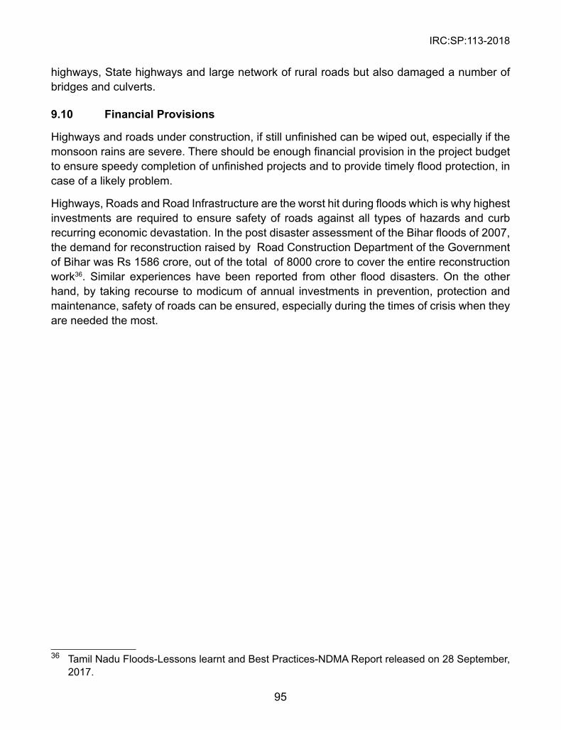
IRC:SP:113-2018
95
highways, State highways and large network of rural roads but also damaged a number of bridges and culverts.
9.10 Financial Provisions
Highways and roads under construction, if still unfinished can be wiped out, especially if the monsoon rains are severe. There should be enough financial provision in the project budget to ensure speedy completion of unfinished projects and to provide timely flood protection, in case of a likely problem.
Highways, Roads and Road Infrastructure are the worst hit during floods which is why highest investments are required to ensure safety of roads against all types of hazards and curb recurring economic devastation. In the post disaster assessment of the Bihar floods of 2007, the demand for reconstruction raised by Road Construction Department of the Government of Bihar was Rs 1586 crore, out of the total of 8000 crore to cover the entire reconstruction work36. Similar experiences have been reported from other flood disasters. On the other hand, by taking recourse to modicum of annual investments in prevention, protection and maintenance, safety of roads can be ensured, especially during the times of crisis when they are needed the most.
36 Tamil Nadu Floods-Lessons learnt and Best Practices-NDMA Report released on 28 September, 2017.
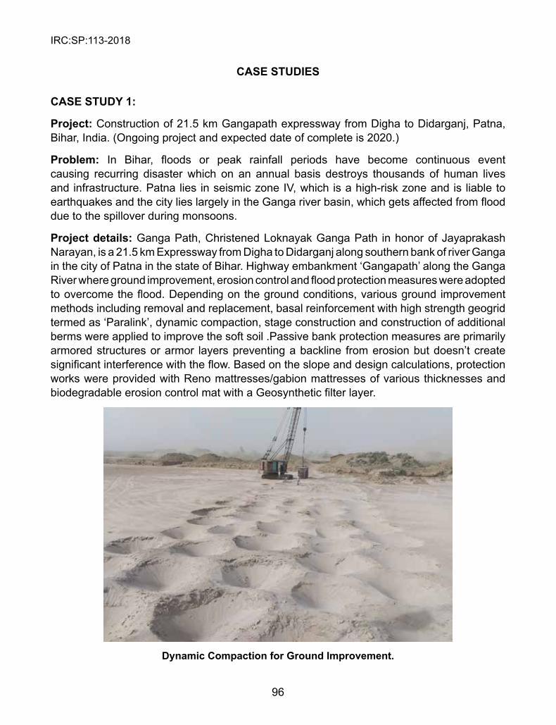
IRC:SP:113-2018
96
CAsE sTUDIEs
CAsE sTUDY 1:
Project: Construction of 21.5 km Gangapath expressway from Digha to Didarganj, Patna, Bihar, India. (Ongoing project and expected date of complete is 2020.)
Problem: In Bihar, floods or peak rainfall periods have become continuous event causing recurring disaster which on an annual basis destroys thousands of human lives and infrastructure. Patna lies in seismic zone IV, which is a high-risk zone and is liable to earthquakes and the city lies largely in the Ganga river basin, which gets affected from flood due to the spillover during monsoons.
Project details: Ganga Path, Christened Loknayak Ganga Path in honor of Jayaprakash Narayan, is a 21.5 km Expressway from Digha to Didarganj along southern bank of river Ganga in the city of Patna in the state of Bihar. Highway embankment ‘Gangapath’ along the Ganga River where ground improvement, erosion control and flood protection measures were adopted to overcome the flood. Depending on the ground conditions, various ground improvement methods including removal and replacement, basal reinforcement with high strength geogrid termed as ‘Paralink’, dynamic compaction, stage construction and construction of additional berms were applied to improve the soft soil .Passive bank protection measures are primarily armored structures or armor layers preventing a backline from erosion but doesn’t create significant interference with the flow. Based on the slope and design calculations, protection works were provided with Reno mattresses/gabion mattresses of various thicknesses and biodegradable erosion control mat with a Geosynthetic filter layer.
Dynamic Compaction for Ground Improvement.
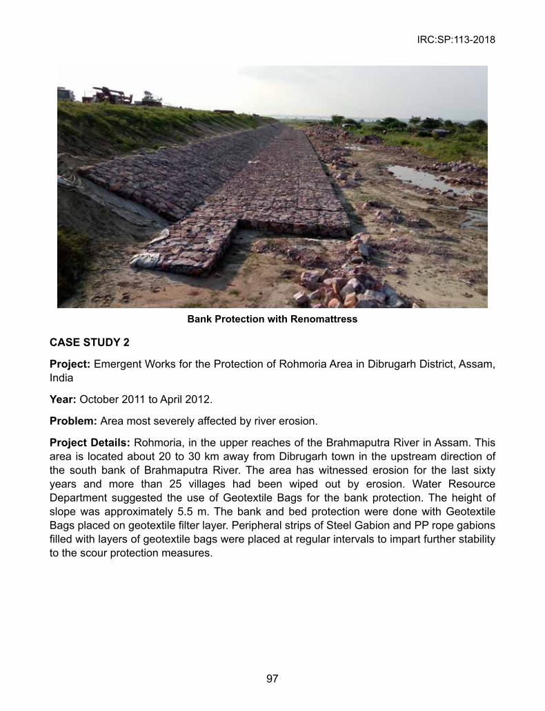
IRC:SP:113-2018
97
Bank Protection with Renomattress
CAsE sTUDY 2
Project: Emergent Works for the Protection of Rohmoria Area in Dibrugarh District, Assam, India
Year: October 2011 to April 2012.
Problem: Area most severely affected by river erosion.
Project Details: Rohmoria, in the upper reaches of the Brahmaputra River in Assam. This area is located about 20 to 30 km away from Dibrugarh town in the upstream direction of the south bank of Brahmaputra River. The area has witnessed erosion for the last sixty years and more than 25 villages had been wiped out by erosion. Water Resource Department suggested the use of Geotextile Bags for the bank protection. The height of slope was approximately 5.5 m. The bank and bed protection were done with Geotextile Bags placed on geotextile filter layer. Peripheral strips of Steel Gabion and PP rope gabions filled with layers of geotextile bags were placed at regular intervals to impart further stability to the scour protection measures.
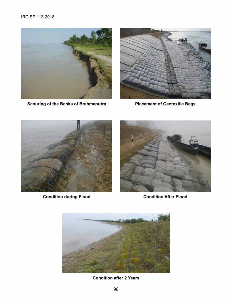
IRC:SP:113-2018
98
scouring of the Banks of Brahmaputra Placement of Geotextile Bags
Condition during Flood Condition After Flood
Condition after 2 Years
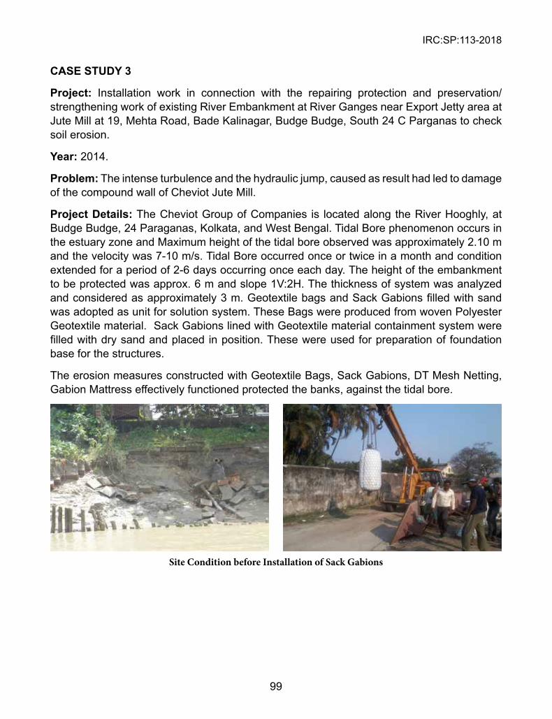
IRC:SP:113-2018
99
CAsE sTUDY 3
Project: Installation work in connection with the repairing protection and preservation/strengthening work of existing River Embankment at River Ganges near Export Jetty area at Jute Mill at 19, Mehta Road, Bade Kalinagar, Budge Budge, South 24 C Parganas to check soil erosion.
Year: 2014.
Problem: The intense turbulence and the hydraulic jump, caused as result had led to damage of the compound wall of Cheviot Jute Mill.
Project Details: The Cheviot Group of Companies is located along the River Hooghly, at Budge Budge, 24 Paraganas, Kolkata, and West Bengal. Tidal Bore phenomenon occurs in the estuary zone and Maximum height of the tidal bore observed was approximately 2.10 m and the velocity was 7-10 m/s. Tidal Bore occurred once or twice in a month and condition extended for a period of 2-6 days occurring once each day. The height of the embankment to be protected was approx. 6 m and slope 1V:2H. The thickness of system was analyzed and considered as approximately 3 m. Geotextile bags and Sack Gabions filled with sand was adopted as unit for solution system. These Bags were produced from woven Polyester Geotextile material. Sack Gabions lined with Geotextile material containment system were filled with dry sand and placed in position. These were used for preparation of foundation base for the structures.
The erosion measures constructed with Geotextile Bags, Sack Gabions, DT Mesh Netting, Gabion Mattress effectively functioned protected the banks, against the tidal bore.
Site Condition before Installation of Sack Gabions
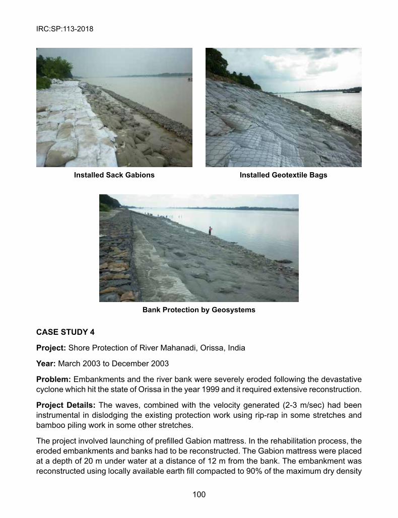
IRC:SP:113-2018
100
CAsE sTUDY 4
Project: Shore Protection of River Mahanadi, Orissa, India
Year: March 2003 to December 2003
Problem: Embankments and the river bank were severely eroded following the devastative cyclone which hit the state of Orissa in the year 1999 and it required extensive reconstruction.
Project Details: The waves, combined with the velocity generated (2-3 m/sec) had been instrumental in dislodging the existing protection work using rip-rap in some stretches and bamboo piling work in some other stretches.
The project involved launching of prefilled Gabion mattress. In the rehabilitation process, the eroded embankments and banks had to be reconstructed. The Gabion mattress were placed at a depth of 20 m under water at a distance of 12 m from the bank. The embankment was reconstructed using locally available earth fill compacted to 90% of the maximum dry density
Installed sack Gabions Installed Geotextile Bags
Bank Protection by Geosystems
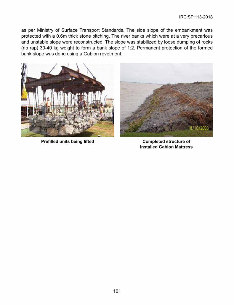
IRC:SP:113-2018
101
as per Ministry of Surface Transport Standards. The side slope of the embankment was protected with a 0.6m thick stone pitching. The river banks which were at a very precarious and unstable slope were reconstructed. The slope was stabilized by loose dumping of rocks (rip rap) 30-40 kg weight to form a bank slope of 1:2. Permanent protection of the formed bank slope was done using a Gabion revetment.
Prefilled units being lifted Completed structure of Installed Gabion Mattress
IRC:SP:113-2018
102
REFERENCEs
Is Codes: 1. IS 12094 (2000): “Guidelines for Planning and Design of River Embankments (Levees)”, Bureau
of Indian Standards, New Delhi. 2. IS 10752 (1983): “Dimensions and Testing Requirements of Landing Gears for Mounting on Semi-
Trailers”, Bureau of Indian Standards, New Delhi. 3. IS 8237 (1985): “Code of Practice for Protection of Slope for Reservoir Embankments”, Bureau of
Indian Standards, New Delhi. 4. IS 10751(1994): “Planning and Design of Guide Banks for Alluvial Rivers-Guidelines”, Bureau of
Indian Standards, New Delhi. 5. IS 14262 (1995): “Planning and Design of Revetments-Guidelines”, Bureau of Indian Standards,
New Delhi. 6. IS 8408 (1994): “Planning and Design of Groynes in Alluvial River-Guidelines”, Bureau of Indian
Standards, New Delhi. IRC Guidelines: 1. IRC:56 (1974): “Recommended Practice for Treatment of Embankment Slopes for Erosion
control”, Indian Roads Congress, New Delhi.2. IRC:89 (1997): “Guidelines for Design and Construction of River Training and Control Works for
Road Bridges”, Indian Road Congress, New Delhi. International Codes/Guidelines: 1. Guidelines for Planning Authorities (2009): “The Planning System and Flood Risk Management”,
Government of Ireland. 2. Flood Control (2002): “Technical Standards and Guidelines for Planning and Design-Volume-I”,
Department of Public Works and Highways, Japan. 3. Resource Manual on Flash Flood Management (2012): “Module 3- Structural Measures”,
International Centre for Integrated Mountain Development, Kathmandu. 4. HEC-11(1989): “Design of Riprap Revetment”, Federal Highway Administration, Washington,
D.C.5. HEC-23 (2009): “Bridge Scour and Stream instability Counter Measures: Experience, Selection
and Design Guidelines”, Federal Highway Administration, Washington, D.C.6. Procedures Manual (2008): “Road Construction and Maintenance-Version 2.1”, Bantay Lansangan,
Government of Australia. 7. “Constructing Waterway Crossings-A Guide on Building Road and (Bridge/Culvert) Crossings
across Melbourne’s Waterways and Drains”, Melbourne Water Corporation, Australia. 8. SEPA (2010): “Engineering in the Water Environment: Good Practice Guide River Crossings-2nd
Edition”, Scottish Government, Scotland. 9. Design Guide (2010): “Fluvial Design Guide”, Environment Agency. 10. GRI GT 10 (2012): “Test Methods, Properties and Frequencies for High Strength Geotextile Tubes
used as Coastal and Riverine Structures”, Geosynthetic Institute, USA.11. GRI GT 11 (2012): “Standard Practice for Installation of Geotextile Tubes used for Coastal and
Riverine Solutions”, Geosynthetic Institute, USA. 12. FHWA HI 95-038 (1995): “Geosynthetic Design and Construction Guidelines”, Federal Highway
Administration, Washington, D.C.
IRC:SP:113-2018
103
BIBLIOGRAPHY
1. RJNA (2014): Phase-01, “Rapid Joint Needs Assessment Report–Jammu & Kashmir Floods”.2. CWC Handbook (2012): “Flood Protection, Anti Erosion and River Training Works”, Flood
Management Organisation, New Delhi. 3. The Rock Manual (2007): “The Use of Rock in Hydraulic Engineering”, CIRIA, London. 4. CPWD (2009): “Specifications-Volume-1”, Director General of Works, CPWD, Nirman Bhawan,
New Delhi. 5. Robert Lamb, Peter Mantz, Serter Atabay & Jeremy Benn: “Recent Advances in Modelling Flood
Water Levels at Bridges and Culverts”.6. The Telegraphindia.com/Bihar-floods.7. www.ndtv.com/Jammu-floods.
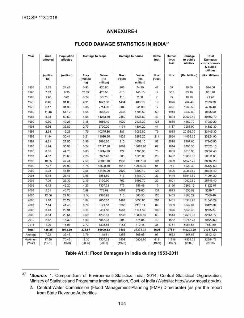
IRC:SP:113-2018
104
ANNEXURE-I
FLOOD DAMAGE sTATIsTICs IN INDIA37
Year Area affected
Population affected
Damage to crops Damage to house Cattle lost
Human lives lost
Damage to public utilities
Total Damages
crops houses & public utilities
(million ha)
(million) Area (million
ha)
Value (Rs
million)
Nos. (’000)
Value (Rs
million)
Nos. (‘000)
Nos. (Rs. Million) (Rs. Million)
1953 2.29 24.48 0.93 420.80 265 74.20 47 37 29.00 524.00
1960 7.53 8.35 21.27 425.50 610 143.10 14 510 63.10 631.70
1965 1.46 3.61 0.27 58.70 113 2.00 7 79 10.70 71.40
1970 8.46 31.83 4.91 1627.80 1434 486.10 19 1076 764.40 2873.30
1975 6.17 31.36 3.85 2714.90 804 341.00 17 686 1660.50 4716.40
1980 11.46 54.12 5.55 3663.70 2533 1708.50 59 1913 3032.80 8405.00
1985 8.38 59.59 4.65 14253.70 2450 5838.60 43 1804 20500.40 40592.70
1990 9.30 40.26 3.18 6956.10 1020 2137.30 134 1855 4552.70 17089.20
1991 6.36 33.89 2.70 5790.20 1134 1804.20 41 1187 7288.90 14883.30
1992 2.64 19.26 1.75 10275.80 387 3082.80 79 1533 20106.70 33445.30
1993 11.44 30.41 3.21 13086.30 1926 5283.20 211 2864 14455.30 33824.90
1994 4.81 27.55 3.96 8886.20 915 1652.10 52 2078 7407.60 17945.90
1995 5.24 35.93 3.24 17147.90 2002 13078.90 62 1814 6796.30 37023.10
1996 8.05 44.73 3.83 11244.90 727 1765.90 73 1803 8613.90 30057.40
1997 4.57 29.66 2.26 6927.40 505 1525.00 28 1402 19859.30 28311.80
1998 10.85 47.44 7.50 25941.70 1933 11087.80 107 2889 51577.70 88607.20
1999 7.77 27.99 1.75 18508.70 1613 12990.60 91 745 4628.30 36127.60
2000 5.38 45.01 3.58 42466.20 2629 6809.40 123 2606 39369.80 88645.40
2001 6.18 26.46 3.96 6884.80 716 8164.70 33 1444 56044.60 71094.20
2002 7.09 26.32 2.19 9130.90 762 5993.70 22 1001 10620.80 25745.40
2003 6.12 43.20 4.27 7307.23 775 756.48 15 2166 3262.15 11325.87
2004 5.31 43.73 2.89 778.69 1664 879.60 134 1813 1656.09 3529.71
2005 12.56 22.93 12.30 2370.92 716 380.53 120 1455 4688.22 7660.49
2006 1.10 25.22 1.82 2850.67 1497 3636.85 267 1431 13303.93 21546.29
2007 7.14 41.40 8.79 3121.53 3280 2113.11 89 3389 8049.04 13425.34
2008 3.43 29.91 3.19 3401.56 1567 1141.89 102 2876 5046.48 9595.34
2009 3.84 29.54 3.59 4232.61 1236 10809.80 63 1513 17509.35 32554.77
2010 2.62 18.30 4.99 5887.38 294 875.95 40 1582 12757.25 19520.59
2011 1.90 15.97 2.72 1393.85 1153 410.48 36 1761 6053.57 7857.89
Total 426.25 1913.39 223.57 66009.63 7402 33373.32 5699 97551 110203.29 213114.90Average 7.22 32.43 3.79 1118.81 1255 565.65 97 1653 1867.85 3612.12
Maximum (Year)
17.50 (1978)
70.45 (1978)
12.30 (2005)
7307.23 (2003)
3508 (1978)
10809.80 618 (1979)
11316 (1977)
17509.35 (2009)
32554.77 (2009)
Table A1.1: Flood Damages in India during 1953-2011
37 *Source: 1. Compendium of Environment Statistics India, 2014, Central Statistical Organization, Ministry of Statistics and Programme Implementation, Govt. of India (Website: http://www.mospi.gov.in).2. Central Water Commission (Flood Management Planning (FMP) Directorate) (as per the report
from State Revenue Authorities
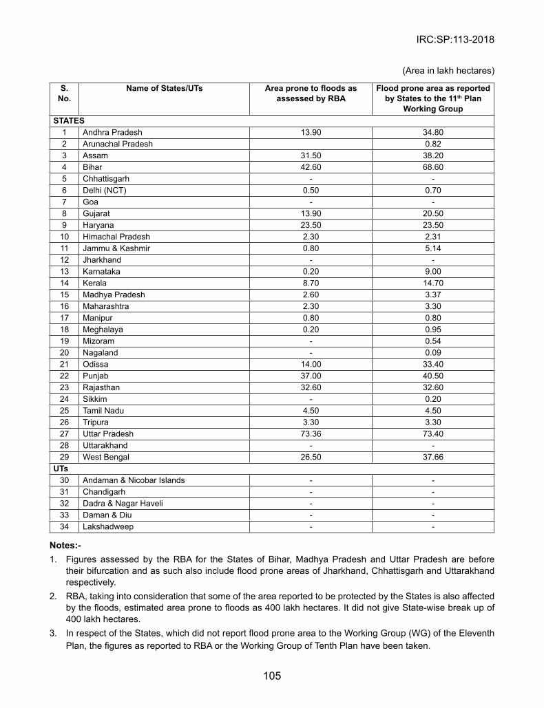
IRC:SP:113-2018
105
(Area in lakh hectares)
s. No.
Name of states/UTs Area prone to floods as assessed by RBA
Flood prone area as reported by states to the 11th Plan
Working GroupsTATEs
1 Andhra Pradesh 13.90 34.802 Arunachal Pradesh 0.823 Assam 31.50 38.204 Bihar 42.60 68.605 Chhattisgarh - -6 Delhi (NCT) 0.50 0.707 Goa - -8 Gujarat 13.90 20.509 Haryana 23.50 23.5010 Himachal Pradesh 2.30 2.3111 Jammu & Kashmir 0.80 5.1412 Jharkhand - -13 Karnataka 0.20 9.0014 Kerala 8.70 14.7015 Madhya Pradesh 2.60 3.3716 Maharashtra 2.30 3.3017 Manipur 0.80 0.8018 Meghalaya 0.20 0.9519 Mizoram - 0.5420 Nagaland - 0.0921 Odissa 14.00 33.4022 Punjab 37.00 40.5023 Rajasthan 32.60 32.6024 Sikkim - 0.2025 Tamil Nadu 4.50 4.5026 Tripura 3.30 3.3027 Uttar Pradesh 73.36 73.4028 Uttarakhand - -29 West Bengal 26.50 37.66
UTs30 Andaman & Nicobar Islands - -31 Chandigarh - -32 Dadra & Nagar Haveli - -33 Daman & Diu - -34 Lakshadweep - -
Notes:-1. Figures assessed by the RBA for the States of Bihar, Madhya Pradesh and Uttar Pradesh are before
their bifurcation and as such also include flood prone areas of Jharkhand, Chhattisgarh and Uttarakhand respectively.
2. RBA, taking into consideration that some of the area reported to be protected by the States is also affected by the floods, estimated area prone to floods as 400 lakh hectares. It did not give State-wise break up of 400 lakh hectares.
3. In respect of the States, which did not report flood prone area to the Working Group (WG) of the Eleventh Plan, the figures as reported to RBA or the Working Group of Tenth Plan have been taken.
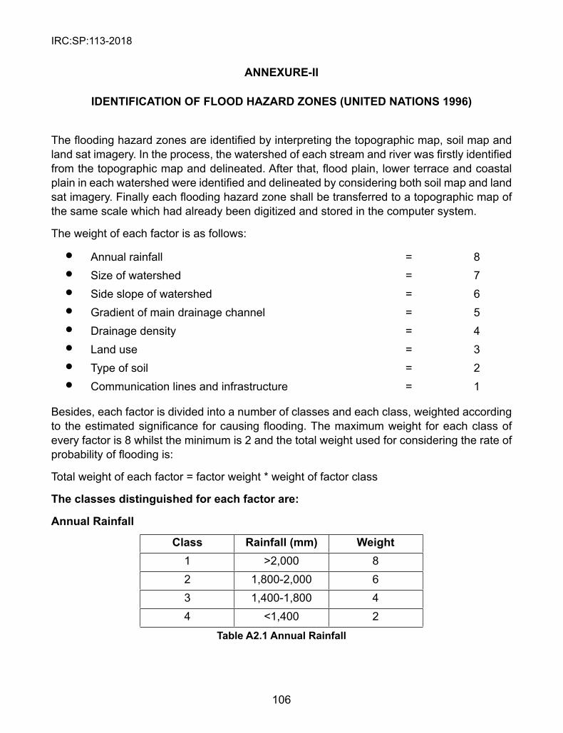
IRC:SP:113-2018
106
ANNEXURE-II
IDENTIFICATION OF FLOOD HAZARD ZONEs (UNITED NATIONs 1996)
The flooding hazard zones are identified by interpreting the topographic map, soil map and land sat imagery. In the process, the watershed of each stream and river was firstly identified from the topographic map and delineated. After that, flood plain, lower terrace and coastal plain in each watershed were identified and delineated by considering both soil map and land sat imagery. Finally each flooding hazard zone shall be transferred to a topographic map of the same scale which had already been digitized and stored in the computer system.
The weight of each factor is as follows:
l Annual rainfall = 8l Size of watershed = 7l Side slope of watershed = 6l Gradient of main drainage channel = 5l Drainage density = 4l Land use = 3l Type of soil = 2l Communication lines and infrastructure = 1
Besides, each factor is divided into a number of classes and each class, weighted according to the estimated significance for causing flooding. The maximum weight for each class of every factor is 8 whilst the minimum is 2 and the total weight used for considering the rate of probability of flooding is:
Total weight of each factor = factor weight * weight of factor class
The classes distinguished for each factor are:
Annual Rainfall
Class Rainfall (mm) Weight1 >2,000 82 1,800-2,000 63 1,400-1,800 44 <1,400 2
Table A2.1 Annual Rainfall

IRC:SP:113-2018
107
size of the Watershed
Class size (km2) Weight1 >350 82 250-350 63 150-250 44 70-150 25 <70
Table A2.2 size of Watershed
slope percentage of the Watershed
Class slope (%) Weight1 >100 82 45-100 73 30-45 54 15-30 35 15 2
Table A2.3 Percentage of side slope of the Watershed, weighted according to Krumbien (1965).
Gradient of the main stream of the watershed
Calculating the gradient of the main stream of watershed:
River and stream gradient = (H2-H1) * 100 DH1 = altitude of the highest point of the slope at the upper river or stream channel
(in meters)H2 = the altitude of the outlet of the river or stream (in meters)D = Distance of H1 to H2 (in meters) For the main river or stream it is the outlet to the main water body such as the lake or the sea. For a small tributary, it is the outlet to the main river or main stream.
Class slope (%) Weight1 >5 82 4-5 73 3-4 64 2-3 55 1-2 36 <1 2
Table A2.4 Gradient of the Main stream of Watershed
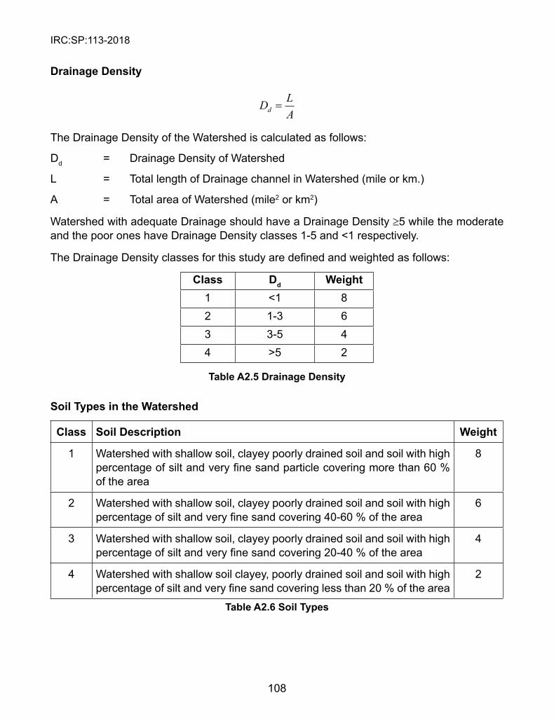
IRC:SP:113-2018
108
Drainage Density
D LAd =
The Drainage Density of the Watershed is calculated as follows:
Dd = Drainage Density of Watershed
L = Total length of Drainage channel in Watershed (mile or km.)
A = Total area of Watershed (mile2 or km2)
Watershed with adequate Drainage should have a Drainage Density ≥5 while the moderate and the poor ones have Drainage Density classes 1-5 and <1 respectively.
The Drainage Density classes for this study are defined and weighted as follows:
Class Dd Weight1 <1 82 1-3 63 3-5 44 >5 2
Table A2.5 Drainage Density
soil Types in the Watershed
Class soil Description Weight
1 Watershed with shallow soil, clayey poorly drained soil and soil with high percentage of silt and very fine sand particle covering more than 60 % of the area
8
2 Watershed with shallow soil, clayey poorly drained soil and soil with high percentage of silt and very fine sand covering 40-60 % of the area
6
3 Watershed with shallow soil, clayey poorly drained soil and soil with high percentage of silt and very fine sand covering 20-40 % of the area
4
4 Watershed with shallow soil clayey, poorly drained soil and soil with high percentage of silt and very fine sand covering less than 20 % of the area
2
Table A2.6 soil Types

IRC:SP:113-2018
109
Land use of Watershed
Considering the land use map compiled from the present (1996) land sat imagery of the area, the class and weight of each land use class is as follows:
Class Land use Weight1 Natural forest, perennial crops and fruit tree cover less than 10 % of
total Watershed area8
2 Natural forest, perennial crops and fruit tree cover 10-20 % of total Watershed area
7
3 Natural forest, perennial crops and fruit tree cover 20-40 % of total Watershed area
5
4 Natural forest, perennial crops and fruit tree cover 40-60 % of total Watershed area
3
5 Natural forest, perennial crops and fruit tree cover more than 60 % of total water area
2
Table A2.7 Land use Types
Communication Line and other Infrastructure Highways, roads, railways, tracks and other infrastructure that obstruct the flow of the river and stream promote flooding. The classes and weight of each class of this factor are as follows:
Class Infrastructure Weight1 Watershed area that has infrastructure obstructing the flow direction of
stream and river within the flood hazard zone at more than 10 locations8
2 Watershed area that has infrastructure obstructing the flow direction of stream and river within the flood hazard zone at 6-10 locations
6
3 Watershed area that has infrastructure obstructing the flow direction of stream and river within the flood hazard zone at 3-5 locations
4
4 Watershed area that has infrastructure obstructing the flow direction of stream and river within the flood hazard zone at less than <3 locations
2
Table A2.8 Infrastructure
Based on the weight of every factor and its class, the maximum total weight of each factor is the result of the multiplication of such factor weight with the weight of its dividing first class. Thus, maximum total weight of the factors rainfall, size of watershed, side slope, slope gradient, drainage density, land use, soil type, and infrastructure are 64, 56, 48, 40, 32, 24, 16, and 8 respectively. The sum of these total maximum weights is 288.
The total minimum weight of each factor, is the result of the multiplication of the factor weight with the weight of its lowest class. These are 16, 14, 12, 10, 8, 9, 4, and 2 respectively and the summed minimum total weight is 75.

IRC:SP:113-2018
110
Considering this, the total weight of the flood hazard zone with the highest probability to be flooded 288 whilst the lowest probability is 75.
Considering the statistic standard deviation values of the total weight data obtained for the study area, the weight of each class is given as: l High = 183-288l Moderate = 107-182l Low = 75-106

IRC:SP:113-2018
INDIAN ROADS CONGRESS
2018
GUIDELINES
ON
FLOOD DISASTER MITIGATION
FOR HIGHWAY ENGINEERS
(The Official amendments to this document would be published bythe IRC in its periodical, ‘Indian Highways’ which shall be
considered as effective and as part of the Code/Guidelines/Manual,etc. from the date specified therein)