
Guidelines for New and Existing Continuously Operating...
34
CORS Guidelines 1 of 33 Guidelines for New and Existing Continuously Operating Reference Stations (CORS) National Geodetic Survey National Ocean Survey, NOAA Silver Spring, MD 20910 February 2006
Transcript of Guidelines for New and Existing Continuously Operating...
CORS Guidelines 1 of 33
Guidelines for New and Existing ContinuouslyOperating Reference Stations (CORS)
National Geodetic SurveyNational Ocean Survey, NOAA
Silver Spring, MD 20910February 2006
CORS Guidelines 2 of 33
Table of Contents
Summary of Updates .................................................................................................. 3Introduction ................................................................................................................ 4Conventions and Definitions....................................................................................... 4Time of Applicability of Guidelines............................................................................ 4Procedures for Becoming a CORS ............................................................................. 5Guidelines for Establishing and Operating a CORS ................................................. 6
A. General Site Operator Requirements ............................................................... 6B. Monument .......................................................................................................... 6
B.1. Stability......................................................................................................... 6B.2. Location, Obstructions, and Radio Frequency Environment .......................... 7
B.2.a. Location................................................................................................. 7B.2.b. Obstructions........................................................................................... 7B.2.c. Radio Frequency Environment ............................................................... 7
B.3. Ground-based Monument .............................................................................. 7B.3.a. Pillar ...................................................................................................... 7B.3.b. Braced ................................................................................................... 8
B.4. Roof-based Monument .................................................................................. 8B.4.a. Building Characteristics ......................................................................... 8B.4.b. Location and Attaching to a Building .................................................... 8
B.5. Attaching Antenna, Mount and Monument .................................................... 8B.6. Orienting Antenna......................................................................................... 9B.7. Antenna Cable............................................................................................... 9
C. Equipment.......................................................................................................... 9C.1. Antenna........................................................................................................ 10C.2. Antenna Radome.......................................................................................... 10C.3. Receiver, Settings, and Power Supply........................................................... 10
D. Communications, and Data Archiving............................................................. 11E. Site Metadata .................................................................................................... 12
E.1. Digital Photographs ...................................................................................... 12E.2. Site Log........................................................................................................ 13
F. Assessment of National Versus Cooperative CORS ........................................ 13G. Cooperative CORS Web Page Specifications....................................................14H. Quality Control and Day-to-Day Site Operations........................................... 14
APPENDIX 1: Form for Evaluating a Proposed CORS site.................................... 16APPENDIX 2: Site Log Instructions......................................................................... 19APPENDIX 3: Blank Site Log................................................................................... 23APPENDIX 4: Sample Site Log................................................................................. 29
CORS Guidelines 3 of 33
Summary of Updates
Guidelines Effective: 1 January 2006Document Updated: 21 June 2006Revisions:19 Jul 2006Section E2 added link for blank log and corrected reference for sample log.
Appendix 3 modified location of blank log.28 Mar 2006 Fixed two bad URL’s08 Feb 2006Procedures: Added explanation for appeals of SST modification request; Added
explanation of applicability of guidelines to existing stations. Modified Proceduresfor becoming a CORS, requested native binary data rather than RINEX and accessto ftp site; Section B.5, added explanation for need of a leveling and orientingdevice, restricted use of tribrachs, corrected filename how_to_modify_a_tribrachadaptor; C.2. Defined PCV; D corrected GPS to UTC time; D. National archiving bysite operator of native binary files increased from 14 days to 30 days; D correctederror in file name for RINEX archive and specified file name for archivingobs,nav,eph etc files; E.1 Azimuthal photographs must include the antenna in thepicture if at all possible; Previous G. was Day-to-Day Operations now CooperativeCORS Web Specifications H. Day-to-day specifications; Appendix 1 Completelyrevised to make it consistent with sections in this document and easier to understand.
15 Dec 2005 Expanded section on procedures for becoming a CORS. Clarified language in SectionsB.3.a, B.4.b, B.5; B.7 expanded discussion on possible antenna cable problems andlightning arrestors; E.1 specified photograph resolution.
04 Nov 2005 Corrected 1 typo.14 Oct 2005 Corrected typos and wrong URL’s.07 Oct 2005 Added section on monument stability.22 Sep 2005 Added cover page.20 Sep 2005 Expanded section on procedures for becoming a CORS.19 Sep 2005 Reordered sections switched A with C.

CORS Guidelines 4 of 33
NGS welcomes comments on any part of these guidelines.Please contact Giovanni Sella [email protected] [email protected]
CORS Guidelines 5 of 33
IntroductionThis document outlines the requirements and recommendations for establishing and operating GPS
stations in the Continuously Operating Reference Station (CORS) network, managed by NOAA’sNational Geodetic Survey (NGS). The CORS network is a multi-purpose cooperative endeavorinvolving more than 150 government, academic, commercial, and private organizations. Althoughparticipation in the CORS network is voluntary site operators must adhere to certain basic standardsand conventions. CORS sites have a fundamental role in establishing and giving access to theNational Spatial Reference System. These guidelines aim to minimize GPS signal distortion andmaximize the quality of calculated positions, in accordance with models used in processing GPSdata, to obtain centimeter to sub-centimeter accuracy.
NGS emphasizes it will not automatically include a station in the CORS network simply becauseit meets the criteria described in this document. Selection is made on a case-by-case basis; takinginto account current CORS network coverage needs, the quality of data and robustness ofcommunication of existing or potential nearby stations.
Conventions and DefinitionsThe following conventions have been adopted for this document.
The term “must” means that compliance is required; the term “should” implies that compliance isstrongly recommended, but not required.
Monument: The structure (e.g., pillar, building, etc), including the mount, which keeps the GPSantenna attached to earth’s surface.
Mount: The device used to attach the antenna to the monument.Mark: This is a unique and permanent point on the monument to which the antenna reference point
is measured. This mark must remain invariant with respect to the monument.Antenna Reference Point (ARP): The point on the exterior of the antenna to which NGS references
the antenna phase center position.Antenna phase center: The electrical point, within or outside an antenna, at which the GPS signal is
measured. The realization of the phase center is determined by the set of antenna phase centervariations (PCV) corrections that have been defined/adopted by NGS to account for the non-ideal electrical response as a function of elevation and azimuth angles.
Antenna eccentricity: The vertical and horizontal distances from the mark to the ARP.Site operator: Point of contact responsible for operating the CORS siteSite log: Plain ASCII file that contains all historical information about a site and details the
equipment and monument used.
Time of Applicability of GuidelinesCORS sites accepted before 1 January 2006 may deviate from monumentation requirements
(Sections A and B), but must comply with all C.3 Equipment Settings, D: Communications and DataArchiving, and D: Site Metadata.
CORS sites accepted after 1 January 2006 must abide by all sections of the guidelines.The guidelines will continue to be revised as technology and NGS’s needs change. NGS will be
responsible for ensuring that site operators are informed of any needed changes and giving them anappropriate time frame to incorporate any changes.
CORS Guidelines 6 of 33
Procedures for Becoming a CORS1) Site operators should ensure that their site meets all the criteria outlined in sections A-E of this
document. NGS strongly recommends that before a CORS site is built NGS is contacted,[email protected] to obtain site specific advice on the proposed location, choice ofequipment, and installation method; this should significantly reduce the chance that a site isrejected or require major and/or costly modifications
2) Send e-mail to [email protected] with “Proposed CORS Site” in the subject line andin the body of the e-mail a short description of the site, its location, and contact information. Byusing this e-mail address rather than an individual NGS employee’s site operators will ensure amore timely response.
3) Supply the following (Appendix 1 will help):- Site photographs (Section E.1.)- Completed site log (Section E.2.)- Link to ftp or http archive with native binary files, if this is not possible then 3 24hr RINEX
observation files with GPS day of year included in the file name.4) NGS will check data quality and verify the completeness and accuracy of the site log5) If between the time the site is proposed and the site is accepted any changes are made to the site or
equipment the site operator must immediately send an e-mail to [email protected] the site ID in the subject line and a description of the changes, including serial numbers orfirmware versions and updated pictures if necessary.
6) NGS’s Site Selection Team (SST) meets every 1-2 weeks and will evaluate the site using thecriteria outlined in Appendix 1. The site will be accepted, conditionally accepted, or declined.The SST consists of 5-6 volunteer members from the Spatial Reference Division and GeosciencesResearch Division, these individuals are involved in a variety of tasks including daily analysis ofCORS data, archiving of CORS data, and installing CORS sites.
If the site is conditionally accepted: The site operator must comply with the requestedchanges. These may involve changing the equipment setup, removing nearbyobstructions, or modifying metadata after which the information is resubmitted withupdated photographs, if needed, to the SST.
If the site is accepted into either National or Cooperative CORS:7) – National - NGS will coordinate with the site operator to establish data flow to NGS and begin
archiving of data7) – Cooperative - NGS will coordinate with the site operator to ensure that the operator’s web page,
and data archiving are acceptable8) Once a site is accepted the site is transferred from the SST to the CORS archive and operations
group. Any changes that are made after this time to the site or equipment must be immediatelysent via e-mail to [email protected] with the site ID in the subject line and adescription of the changes e.g. new serial number(s), firmware versions, updated picture(s), etc.
9) NGS will add the site to the CORS webpage10) NGS will begin analyzing the data and upload all site metadata to NGS’s internal database11) NGS will publish the official coordinates and velocity for the site12) NGS will publish in its newsletter and on its base map the new site.
If a site operator disagrees with the SST decision they are encouraged to appeal the decisionto the SST. They should explain in detail why they believe the decision is not appropriate andhow the guidelines should be modified or reconsidered.
CORS Guidelines 7 of 33
Guidelines for Establishing and Operating a CORSA. General Site Operator Requirements
All correspondence about an accepted and operating CORS site must be sent to:[email protected] with the 4-character site ID in the subject line, or cityand state name if no site ID is assigned. By using this e-mail address rather than anindividual NGS employee’s site operators will ensure a more timely response.
The site operator provides and maintains all CORS equipment. Since NGS does not operate thesite(s) NGS should not be considered the primary verifier of a site’s data quality, the site operatorsshould have their own data integrity checks.
The site operator must inform NGS of any planned outages, changes in equipment and firmware --especially changes in antenna, radome, and physical space surrounding the antenna -- as soonas they become known to the site operator.
A CORS site is expected to have high data quality and a lifetime of at least 15 yrs. The latter alsoapplies to the critical volume of space around the antenna that should remain undisturbed throughoutthe lifetime of the CORS site. Power and Internet outages should be infrequent and short-lived,
B. MonumentSince there is no “perfect” monument, these guidelines only aim to avoid designs that are known to
cause (or are likely to cause) data quality issues, based on designs used in CORS/IGS (InternationalGlobal Navigation Satellite System Service) during the last 12 years.
GOALS: First, ensuring that the antenna is well anchored to the ground is essential so theposition and velocity associated with a given site represents the crustal position and velocityof the site, not just of the antenna. Second, minimize multipath and differences in antennaphase center position as compared to models used in data analysis.
B.1. StabilityA CORS monument should be designed to maximize its stability (maintain a fixed position in
three dimensions) and minimize measurement of near-surface effects. The uppermost part of theground is subject to the greatest amount of motion e.g. soil expansion and contraction due to changesin water saturation, frost heave, soil weathering, thus increasing the depth of the monumentimproves its stability. A detailed discussion of benchmark stability that is equally applicable toCORS monuments is given in “NOAA Manual NOS NGS 1 Geodetic Bench Marks” especiallypages 1-11. See: http://www.ngs.noaa.gov/PUBS_LIB/GeodeticBMs
CORS sites should be designed to be at least Class B and hence minimize the impact of:-Caverns, sink holes, and mines-Areas where there is active fluid/gas pumping.-Frost heave, shrinking and swelling of soil and rock-Soil expansion and contraction-Slope instability-Soil consolidation-Motion intrinsic to a monument e.g. thermal expansion and contraction
CORS Guidelines 8 of 33
NGS strongly recommends that if in doubt about the soil and geologic conditions, a conservative“worst case” scenario is assumed.
B.2. Location, Obstructions and Radio Frequency EnvironmentB.2.a. Location
Choose an open area with minimal obstructions and minimum likelihood of change in theenvironment surrounding the monument; e.g. avoid sites with future tree or shrub growth, buildingadditions, rooftop additions, new antenna masts, satellite dishes, parking lots, chain link fences, etc.B.2.b. Obstructions
No obstructions 10 degrees above the horizon from the ARP and minimal obstructions from 0 to 10degrees.WHY: The greater the volume through which uninterrupted/unreflected signal can reachthe antenna, the greater the likelihood of a robust position estimate. No lightning rods, RTKbroadcast antennas, or any other objects should extend above the antenna or be anywherewithin 3 m of the antenna and all should be below the 0 degree of the horizontal surfacecontaining the ARP.
B.2.c. Radio Frequency EnvironmentThe signals received by a CORS antenna and receiver can be detrimentally affected by interference
from other radio frequency sources (e.g. TV, microwave, FM radio stations, cellular telephones,VHF and UHF repeaters, RADAR, high voltage power lines). This can cause additional noise,intermittent or partial loss of lock or even render sites inoperable. Every effort should be made toavoid proximity to such equipment now and in the future, and all such equipment must bedocumented in the site log.
B.3. Ground-based MonumentB.3.a. Pillar
-Should be approximately 1.5 m above the ground surface to mimic the geometry used at NGS’santenna phase center calibration facility. However, in light of possible obstructions (see B.2.Location, Obstructions, and Radio Frequency Environment), a taller monument may benecessary.
-Must have a deep foundation, Class B, that extends at least 4 m below the frost line and/or thecenter of mass of the pillar must be below the frost line (see B.1. Stability).
-The top of the pillar MUST be narrower than the widest part of the antenna, and the smaller thesurface the better. In constructing the pillar, consider that future antennas may be smaller; hencethe narrower the top of the pillar the better. The distance between the top of the pillar (if it has asurface) and the antenna should be less than 5 cm or greater than 1 GPS wavelength (~20 cm).This will allow enough room to manipulate a leveling and orienting device (see B.5. AttachingAntenna, Mount, and Monument). These recommendations apply to the top of the pillar only; avery narrow pillar would be unstable and not recommended, however tapered pillars are good.WHY: This will mitigate multipath issues. For construction of pillar type monumentsconsult the following web links:www.ngs.noaa.gov/CORS/CorsPP/forum2004/ray.pptgsc.nrcan.gc.ca/geodyn/wcda/gpsmon_e.php
CORS Guidelines 9 of 33
B.3.b. BracedThese monuments are especially stable and well anchored to the ground, although more expensive
than pillars. Extensive diagrams with details of all aspects of constructions are available at:http://pboweb.unavco.org/?pageid=45http://www.unavco.org/facility/project_support/permanent/monumentation/deepdrilled.htmlhttp://www.unavco.org/facility/project_support/permanent/monumentation/sdbm.html
B.4. Roof-based MonumentB.4.a. Building characteristics
Only masonry buildings are permitted and solid brick or reinforced concrete ones arerecommended. The building should have been built at least 5 years previously, to increase thelikelihood that all primary settling of the building has occurred. There should be no visible cracks onthe outside or inside walls. Buildings taller than two stories are not recommended. No wood orsimple metal frame with metal walled buildings, and no metal roofs.
WHY: This will minimize the effects of thermal expansion as well as multipath issues. Thefollowing links are instructive but not exhaustive:www.cement.ca/cement.nsf/0/7427088E8CB2AFF285256BF30063F29C?OpenDocumenthyperphysics.phy-astr.gsu.edu/hbase/tables/thexp.htmlwww.masonryinstitute.com/guide/part4/construction_b2_pg1.html
B.4.b. Location and Attachment to a Building-Stainless steel is recommended for longevity (Angle iron or circular pipe). Aluminum is not
recommended as it has approximately twice the thermal expansion of steel/concrete.-The mount must be bolted directly to the main part of the building; a load-bearing wall near a
corner is recommended.-The use of epoxy and threaded lock adhesives fasteners (bolts/anchors/rods) is strongly
recommended.-Mounting on a chimney is not recommended unless it has been filled with concrete or if it is
particularly robust.-The mount should not interfere with the building’s replaceable roof. This will minimize the
chance that the mount will be disturbed when the roof is replaced.Attaching laterally to a load bearing wall:
The mount should extend about 0.5 m above the roofline and be attached to the building for alength of at least 1 m, with at least 3 anchors/bolts. The ratio of freestanding part to bolted partshould be approximately 1:3.
The bolts/anchors must penetrate directly through the mount, e.g. no u-bolts or unistrut bracketswith metal ties/clamps. Spacers to keep the mount from sitting flush against the wall areacceptable.
Attaching vertically to a master wall:A bolt or rod must be anchored into a load-bearing wall. Take care not to void a roof warranty.
Avoid metal flashing on a parapet wall.
B.5. Attaching Antenna, Mount and MonumentA device must exist between the monument and the antenna that allows: First, the antenna to be
leveled and oriented to north (see B.6. Orienting Antenna). Second, if the antenna is changed,the new ARP must return to the exact same point in 3-dimensional space as the previous ARP,
CORS Guidelines 10 of 33
or the change in position between the mark (See definitions) and the ARP must be measured towithin 1 mm.WHY: If the antenna is simply attached to a threaded rod when it is replaced the new antennamay not return to the same 3-D position or may be oriented differently (the latter would beimmaterial only if the phase center variation model is perfectly symmetrical). Both events wouldrequire a new position to be computed, which is undesirable.
The antenna must be leveled to within 0.15 degrees or 2.5 mm/meter (This is easily achieved usinga good quality spirit level available in most hardware stores)
Tribrach’s are not permitted, as there is no mechanism to lock the adjustable wheels in place.A number of devices exist that will do this:
www.ngs.noaa.gov/CORS/Articles/modifying_a_tribrach_adaptor.pdfwww.unavco.org/facility/project_support/permanent/equipment/mounts/levelingmount.htmlwww.unavco.org/facility/project_support/permanent/equipment/mounts/scignmount.html
B.6. Orienting AntennaThe antenna must be oriented to true north using the convention of aligning the antenna cable
attachment point, unless the antenna has a different inscribed North point. Remember thatdeclination is the angle between magnetic north and true north. A magnetic declination calculatorfor setting a compass correctly is available at:
http://www.ngdc.noaa.gov/seg/geomag/jsp/Declination.jspThe declination used must be recorded in the log file (see E.2. Site Log).
WHY: All antenna phase center patterns assume an oriented antenna, and phase centervalues can differ between north and east by up to a centimeter.
B.7. Antenna CableThe antenna cable should not be under tension. Looping the first section of cable next to the
antenna and attaching it to the mount can best avoid this problem. If the cable is not encased inconduit, then care should be taken that it will not move around and be damaged. Take particular careat any point where the cable is subject to increased friction, e.g. edges and egress points. TypicalGPS antenna cables for CORS (RG213/RG214) have a signal loss of 9 db/100ft/30m at 1Ghz. Totalloss for installed length of cable at a CORS must be 9 db or less, implying a maximum cable lengthof 100ft/30m. If a longer cable is needed then a lower loss cable must be used (The type,manufacturer, and length of cable must be listed in the site log, see E.2).
The antenna cable should directly connect to the receiver and antenna, no connectors should beinserted e.g. TNC to N-type. The junction point of the antenna cable and antenna after the two havebeen connected should be sealed with waterproof material e.g. butyl wrap.
Site operators are strongly recommended to insert a lightning arrestor in the antenna cable betweenthe antenna and the receiver with its own independent ground. The arrestor should be located on theoutside of the building at or near the egress point of the cable into the building. This should protectthe receiver in the event of a lightning strike on or near the antenna. The following URL may behelpful, and clearly indicates the potential signal loss created by a poorly selected arrestor:http://www.unavco.org/facility/project_support/permanent/equipment/lightning/lemp_report.html
C. EquipmentSite operators must keep all receiver firmware updated, and inform NGS as soon as updates occur
by e-mailing [email protected], please specify 4-character site ID in the subject line.
CORS Guidelines 11 of 33
NGS strongly recommends that equipment be upgraded and/or replaced as technology changes, e.g.new GPS signals added. Equipment changes should however be minimized as they have thepotential of resulting in a change in position. If data quality decreases and the site operator is unableto replace /upgrade equipment or otherwise mitigate a problem, NGS may choose to remove the sitefrom the CORS network (see H. Quality Control and Day-to-Day Site Operations)
C.1. Antenna-The antenna must be at least dual-frequency (L1 and L2).-An NGS calibrated phase center model for the antenna model must be available. If the user
chooses to install a radome (see C.2. Antenna Radome), an NGS calibrated antenna phase centermodel for the antenna and radome pair must be available. The NGS database of calibratedantenna and radome combinations is available at:http://www.ngs.noaa.gov/ANTCALWHY: A consistent phase center and ARP for the antenna is essential to tie the GPSmeasurements to the mark. Ignoring the phase center variations can lead to multi-centimeter errors. All analysis of GPS data at NGS requires that an NGS-validated phasecenter model be used to calculate the official positional coordinates for a CORS site.
Antennas must be inspected regularly for damage.
C.2. Antenna RadomeNGS strongly recommends that no antenna radome be used.
WHY: It is well documented that an antenna radome changes the antenna phase centerposition. Its benefit is limited as antennas are constructed so they do not need the“protection” of a radome. The choice of material used, the effects of UV radiation, as wellas possible manufacturing inhomogeneities in the thickness of certain radomes, may createadditional problems in using a single Phase Center Variation (PCV) model for a particularradome model. These two problems imply that either a time-dependent effect on the PCVexists as the radome deteriorates or a calibration of each individual radome is needed, as ageneral model calibration would not be valid e.g.
http://pasadena.wr.usgs.gov/scign/group/dome
If a radome is used, the antenna and radome pair must have been calibrated together by NGS (seeC.1. Antenna).
C.3. Receiver, Settings, and Power SupplyReceivers must be able to:
- Track at least L1 and L2- Track at least 10 satellites above 0 degrees- Automatically switch between operating modes to retain full wavelength L2 when
Antispoofing (AS) is switched on- Provide L1 C/A-code pseudorange or P-code pseudorange and L1 and L2 full wavelength
carrier phase- Sample at a frequency of at least 30-seconds
Receivers must be programmed:
CORS Guidelines 12 of 33
- So that no smoothing is applied to the observables- Track with an elevation cutoff angle of 5 degrees and 0 degrees is strongly preferred- Record at 30, 15, 10, 5 or 1-second sampling intervals- Log hourly blocks (strongly preferred), or 24hr blocks of GPS time. Optimal configuration is
to deliver data in real time to NGS- Track all satellites regardless of health status
WHY: The criteria used by the Department of Defense for designating an unhealthysatellite are not always applicable to certain CORS users.
Receivers must have an uninterrupted power supply with a minimum of 5 minutes backup power,30+ minutes strongly preferred.
D. Communications and Data ArchivingAll data transfers between NGS and the operator’s site must be done via the Internet.NGS must be able to retrieve or receive the data immediately after the hour if logging hourly or
after 2400h GPS time.Site operator’s web and ftp server must operate 24hrs a day.
National CORS Archiving Cooperative CORS ArchivingNGS will create RINEX-2 files that will bearchived by NGS, indefinitely.
Site operator will create RINEX-2 formatteddata that must be stored on-line for a minimumof 30 days.
Native binary data must be made available toNGS immediately after the hour if logginghourly, or after 2400h GPS time.
Site operator must make RINEX-2 dataavailable to the public immediately after thehour if logging hourly, or 2400h GPS time.
Site operator must keep native binary data on-line and accessible by NGS for at least 30days, (NGS will not archive native binarydata).
Site operator may also make native binary dataavailable on-line, 30 days preferred.
All file names and associated dates must be recorded with respect to GPS time (UTC plus 14s) NOTlocal time (Most GPS receivers will convert UTC to GPS time without user input).
Directory structure at operator’s site MUST use the following convention and be all in lowercase:
/base_directory/native/yyyy/ddd/ssss/ssssdddh[mm].[c]/base_directory/rinex/yyyy/ddd/ssss/ssssdddh[mm].yyt.[c]
If a site operator wants to deliver RINEX observation, meteorological, navigation, etc. files as agroup/archive, the files within the archive must be uncompressed and the archive must be labeled:ssssdddh[mm].yy.c
Files must use the following convention all in lowercase, which follows the RINEX convention:ssssdddh[mm].yyt.[c]
CORS Guidelines 13 of 33
base_directory – can be any directory on the site operator’s ftp server where data are going to bestored.
ssss - the four-character site ID (see E.2. Site Log)ddd - the GPS day of year,yyyy – four digit GPS yearh - a letter that corresponds to an hour-long GPS time block (see below) or 0 (zero) for a full 24hr
GPS time block.00 01 02 03 04 05 06 07 08 09 10 11 12 13 14 15 16 17 18 19 20 21 22 23 a b c d e f g h i j k l m n o p q r s t u v w x
mm applies only to sites that record in less than 1 hour time blocks and consists of the minutesafter the hour that the file begins e.g. if 30 minute files are collected then 00 and 30 would beused.
yy - the last two digits of four digit GPS year (e.g. 2004 is 04)t - the file type as:
o – observationd – observation Hatanaka compressed. The source code for creating and uncompressing this
format is available at: ftp://terras.gsi.go.jp/software/RNXCMPm – meteorologicaln – navigations – summary
c - compression is optional, but recommended as it saves bandwidth, but must be one of thefollowing three types:zip – zipgz – gzip GNU zip (preferred) and available at: http://www.gnu.org/software/gzip/gzip.htmZ – UNIX compressed
The native binary files will obviously have the manufacturer specific extensions but should mimicthe afore mentioned format as closely as possible.
E. Site MetadataE.1. Digital Photographs
A set of sharply focused digital photographs, at least 300 dpi at 5”x7”, are required to evaluate anddocument a site. When taking photographs, please remember that their purpose is to give a clearview of the equipment being used, how it is assembled, as well as the space around it for someonewho has not visited the site. Photographs must use the filename specified in bold between thedashes – (where ssss is the 4-charcter site ID). The convention to use for azimuth direction is 000 -north, 090 - east, etc. Jpg format is preferred. The photographs must include:
– ssss_monu.jpg – A photograph showing the monument (pillar/braced/building) and antenna. Theground surface of the building or monument and antenna must be visible.
– ssss_mark.jpg – A photograph showing the mark. If no unique mark exists then a photograph ofthe threaded section of the mount, either laterally or from above the monument should betaken. (If the site has been collecting data then DO NOT REMOVE the antenna and insteadignore this photograph.
– ssss_ant_monu.jpg – A close-up photograph that shows how the antenna is attached to themonument.
CORS Guidelines 14 of 33
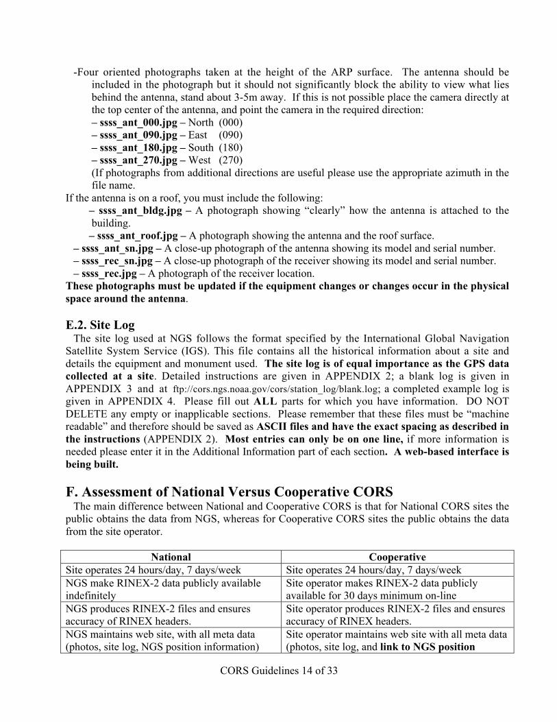
-Four oriented photographs taken at the height of the ARP surface. The antenna should beincluded in the photograph but it should not significantly block the ability to view what liesbehind the antenna, stand about 3-5m away. If this is not possible place the camera directly atthe top center of the antenna, and point the camera in the required direction:– ssss_ant_000.jpg – North (000)– ssss_ant_090.jpg – East (090)– ssss_ant_180.jpg – South (180)– ssss_ant_270.jpg – West (270)(If photographs from additional directions are useful please use the appropriate azimuth in thefile name.
If the antenna is on a roof, you must include the following:– ssss_ant_bldg.jpg – A photograph showing “clearly” how the antenna is attached to thebuilding.– ssss_ant_roof.jpg – A photograph showing the antenna and the roof surface.
– ssss_ant_sn.jpg – A close-up photograph of the antenna showing its model and serial number.– ssss_rec_sn.jpg – A close-up photograph of the receiver showing its model and serial number.– ssss_rec.jpg – A photograph of the receiver location.
These photographs must be updated if the equipment changes or changes occur in the physicalspace around the antenna.
E.2. Site LogThe site log used at NGS follows the format specified by the International Global Navigation
Satellite System Service (IGS). This file contains all the historical information about a site anddetails the equipment and monument used. The site log is of equal importance as the GPS datacollected at a site. Detailed instructions are given in APPENDIX 2; a blank log is given inAPPENDIX 3 and at ftp://cors.ngs.noaa.gov/cors/station_log/blank.log; a completed example log isgiven in APPENDIX 4. Please fill out ALL parts for which you have information. DO NOTDELETE any empty or inapplicable sections. Please remember that these files must be “machinereadable” and therefore should be saved as ASCII files and have the exact spacing as described inthe instructions (APPENDIX 2). Most entries can only be on one line, if more information isneeded please enter it in the Additional Information part of each section. A web-based interface isbeing built.
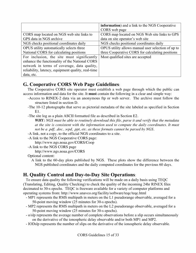
F. Assessment of National Versus Cooperative CORSThe main difference between National and Cooperative CORS is that for National CORS sites the
public obtains the data from NGS, whereas for Cooperative CORS sites the public obtains the datafrom the site operator.
National CooperativeSite operates 24 hours/day, 7 days/week Site operates 24 hours/day, 7 days/weekNGS make RINEX-2 data publicly availableindefinitely
Site operator makes RINEX-2 data publiclyavailable for 30 days minimum on-line
NGS produces RINEX-2 files and ensuresaccuracy of RINEX headers.
Site operator produces RINEX-2 files and ensuresaccuracy of RINEX headers.
NGS maintains web site, with all meta data(photos, site log, NGS position information)
Site operator maintains web site with all meta data(photos, site log, and link to NGS positioninformation) and a link to the NGS CooperativeCORS web page
CORS Guidelines 15 of 33
information) and a link to the NGS CooperativeCORS web page
CORS map located on NGS web site links toGPS data in NGS archive
CORS map located on NGS Web site links to GPSdata on site operator’s web site
NGS checks positional coordinates daily NGS checks positional coordinates dailyOPUS utility automatically selects threeNational CORS for calculating positions
OPUS utility allows manual user selection of up tothree Cooperative CORS for calculating positions
For inclusion, the site must significantlyenhance the functionality of the National CORSnetwork in terms of coverage, data quality,reliability, latency, equipment quality, real-timedata, etc.
Most qualified sites are accepted
G. Cooperative CORS Web Page Guidelines:The Cooperative CORS site operator must establish a web page through which the public can
access information and data for the site. It must contain the following in a clear and simple way:-Access to RINEX-2 data via an anonymous ftp or web server. The archive must follow the
structure listed in section D.-The 10-12 photographs that serve as pictorial metadata of the site labeled as specified in Section
E1.-The site log as a plain ASCII formatted file as described in Section E2.
WHY: NGS must be able to routinely download this file, parse it and verify that the metadataat the site is consistent with the information used to compute the daily coordinates. It mustnot be a .pdf, .doc, .wpd, .ppt, etc. as these formats cannot be parsed by NGS.
-A link, not a copy, to the official NGS coordinates to a site.-A link to the NGS Cooperative CORS page:
http://www.ngs.noaa.gov/CORS/Coop-A link to the NGS CORS page
http://www.ngs.noaa.gov/CORSOptional content:
A link to the 60-day plots published by NGS. These plots show the difference between theNGS published coordinates and the daily computed coordinates for the previous 60 days.
H. Quality Control and Day-to-Day Site Operations:To ensure data quality the following verifications will be made on a daily basis using TEQC
(Translating, Editing, Quality Checking) to check the quality of the incoming 24hr RINEX filesdecimated to 30-s epochs. TEQC is freeware available for a variety of computer platforms andoperating systems from: http://www.unavco.org/facility/software/teqc/teqc.html
- MP1 represents the RMS multipath in meters on the L1 pseudorange observable, averaged for a50-point moving window (25 minutes for 30-s epochs).
- MP2 represents the RMS multipath in meters on the L2 pseudorange observable, averaged for a50-point moving window (25 minutes for 30-s epochs).
- o/slp represents the average number of complete observations before a slip occurs simultaneouslyon the derivative of the ionospheric delay observable and/or both MP1 and MP2.
- IODslp represents the number of slips on the derivative of the ionospheric delay observable.

CORS Guidelines 16 of 33
The TEQC statistics will be supplemented with those obtained by forming the ionospheric freelinear combination of the L1 and L2 phases by the method of double differences. This is the methodused by NGS to calculate daily site coordinates. Note that double differences are dependent on dataquality from two sites, unlike TEQC statistics.
The combination of the aforementioned performance measures will be used to recommendequipment upgrades for prospective or existing sites whose data under-perform compared to itsestablished peers (CORS network). In addition, these results will be used to search for systematiceffects in the CORS network, such as a tendency for a model of receiver or antenna to under-performwhen compared to its peers.
CORS Guidelines 17 of 33
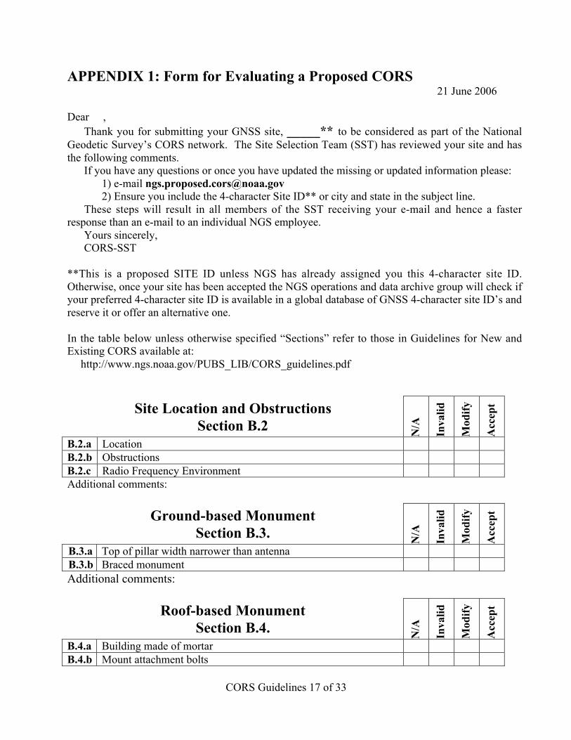
APPENDIX 1: Form for Evaluating a Proposed CORS21 June 2006
Dear ,Thank you for submitting your GNSS site, _____** to be considered as part of the National
Geodetic Survey’s CORS network. The Site Selection Team (SST) has reviewed your site and hasthe following comments.
If you have any questions or once you have updated the missing or updated information please:1) e-mail [email protected]) Ensure you include the 4-character Site ID** or city and state in the subject line.
These steps will result in all members of the SST receiving your e-mail and hence a fasterresponse than an e-mail to an individual NGS employee.
Yours sincerely,CORS-SST
**This is a proposed SITE ID unless NGS has already assigned you this 4-character site ID.Otherwise, once your site has been accepted the NGS operations and data archive group will check ifyour preferred 4-character site ID is available in a global database of GNSS 4-character site ID’s andreserve it or offer an alternative one.
In the table below unless otherwise specified “Sections” refer to those in Guidelines for New andExisting CORS available at:
http://www.ngs.noaa.gov/PUBS_LIB/CORS_guidelines.pdf
Site Location and ObstructionsSection B.2 N
/A
Inva
lid
Mod
ify
Acc
ept
B.2.a LocationB.2.b ObstructionsB.2.c Radio Frequency EnvironmentAdditional comments:
Ground-based MonumentSection B.3. N
/A
Inva
lid
Mod
ify
Acc
ept
B.3.a Top of pillar width narrower than antennaB.3.b Braced monumentAdditional comments:
Roof-based MonumentSection B.4. N
/A
Inva
lid
Mod
ify
Acc
ept
B.4.a Building made of mortarB.4.b Mount attachment bolts
CORS Guidelines 18 of 33
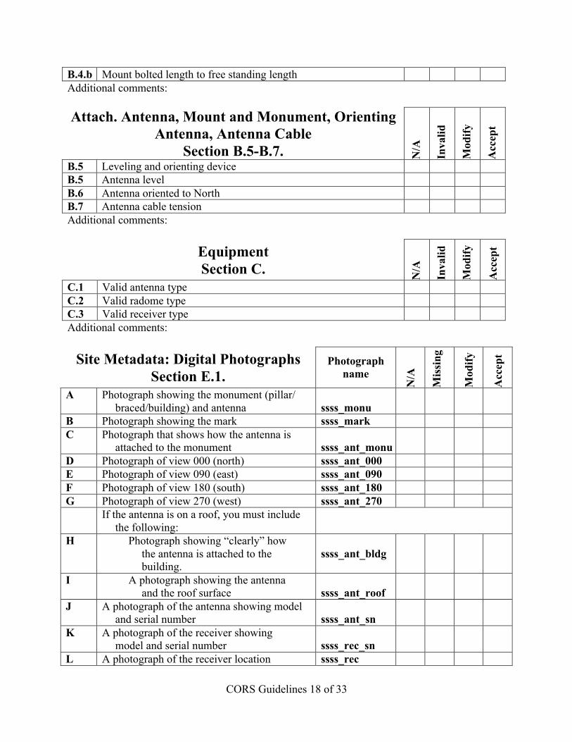
B.4.b Mount bolted length to free standing lengthAdditional comments:
Attach. Antenna, Mount and Monument, OrientingAntenna, Antenna Cable
Section B.5-B.7. N/A
Inva
lid
Mod
ify
Acc
ept
B.5 Leveling and orienting deviceB.5 Antenna levelB.6 Antenna oriented to NorthB.7 Antenna cable tensionAdditional comments:
EquipmentSection C. N
/A
Inva
lid
Mod
ify
Acc
ept
C.1 Valid antenna typeC.2 Valid radome typeC.3 Valid receiver typeAdditional comments:
Site Metadata: Digital PhotographsSection E.1.
Photographname
N/A
Mis
sing
Mod
ify
Acc
ept
A Photograph showing the monument (pillar/braced/building) and antenna ssss_monu
B Photograph showing the mark ssss_markC Photograph that shows how the antenna is
attached to the monument ssss_ant_monuD Photograph of view 000 (north) ssss_ant_000E Photograph of view 090 (east) ssss_ant_090F Photograph of view 180 (south) ssss_ant_180G Photograph of view 270 (west) ssss_ant_270
If the antenna is on a roof, you must includethe following:
H Photograph showing “clearly” howthe antenna is attached to thebuilding.
ssss_ant_bldg
I A photograph showing the antennaand the roof surface ssss_ant_roof
J A photograph of the antenna showing modeland serial number ssss_ant_sn
K A photograph of the receiver showingmodel and serial number ssss_rec_sn
L A photograph of the receiver location ssss_rec
CORS Guidelines 19 of 33
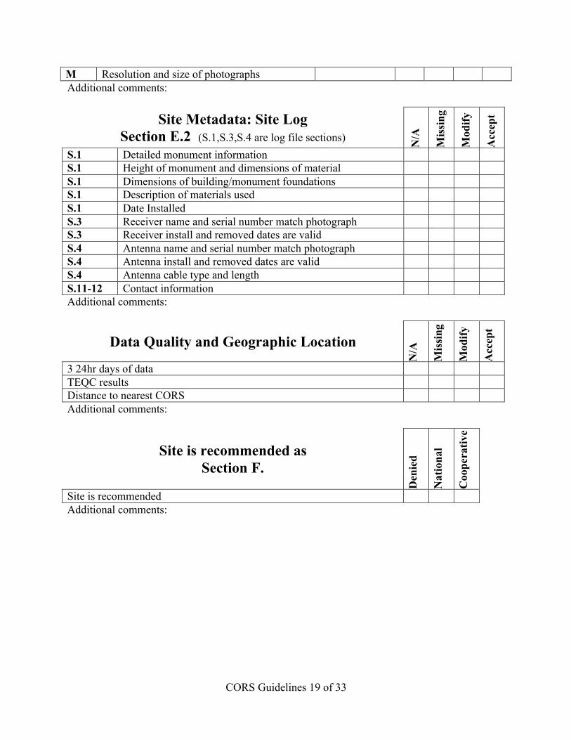
M Resolution and size of photographsAdditional comments:
Site Metadata: Site LogSection E.2 (S.1,S.3,S.4 are log file sections) N
/A
Mis
sing
Mod
ify
Acc
ept
S.1 Detailed monument informationS.1 Height of monument and dimensions of materialS.1 Dimensions of building/monument foundationsS.1 Description of materials usedS.1 Date InstalledS.3 Receiver name and serial number match photographS.3 Receiver install and removed dates are validS.4 Antenna name and serial number match photographS.4 Antenna install and removed dates are validS.4 Antenna cable type and lengthS.11-12 Contact informationAdditional comments:
Data Quality and Geographic Location
N/A
Mis
sing
Mod
ify
Acc
ept
3 24hr days of dataTEQC resultsDistance to nearest CORSAdditional comments:
Site is recommended asSection F.
Den
ied
Nat
iona
l
Coo
pera
tive
Site is recommendedAdditional comments:
CORS Guidelines 20 of 33
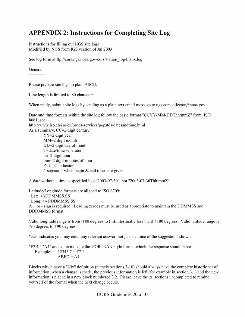
APPENDIX 2: Instructions for Completing Site Log
Instructions for filling out NGS site logsModified by NGS from IGS version of Jul 2003
See log form at ftp://cors.ngs.noaa.gov/cors/station_log/blank.log
General=======
Please prepare site logs in plain ASCII.
Line length is limited to 80 characters.
When ready, submit site logs by sending as a plain text email message to [email protected]
Date and time formats within the site log follow the basic format "CCYY-MM-DDThh:mmZ" from ISO8061; seehttp://www.iso.ch/iso/en/prods-services/popstds/datesandtime.htmlAs a summary, CC=2 digit century
YY=2 digit year MM=2 digit month DD=2 digit day of month T=date/time separator hh=2 digit hour mm=2 digit minutes of hour Z=UTC indicator /=separator when begin & end times are given
A date without a time is specified like "2003-07-30", not "2003-07-30Thh:mmZ"
Latitude/Longitude formats are aligned to ISO 6709: Lat: +/-DDMMSS.SS Long: +/-DDDMMSS.SSA + or - sign is required. Leading zeroes must be used as appropriate to maintain the DDMMSS andDDDMMSS format.
Valid longitude range is from -180 degrees to (infinitesimally less than) +180 degrees. Valid latitude range is-90 degrees to +90 degrees.
"etc" indicates you may enter any relevant answer, not just a choice of the suggestions shown.
"F7.4," "A4" and so on indicate the FORTRAN-style format which the response should have.Example 12345.7 = F7.1
ABED = A4
Blocks which have a "Nix" definition (namely sections 3-10) should always have the complete historic set ofinformation; when a change is made, the previous information is left (for example in section 3.1) and the newinformation is placed in a new block numbered 3.2. Please leave the .x sections uncompleted to remindyourself of the format when the next change occurs.
CORS Guidelines 21 of 33
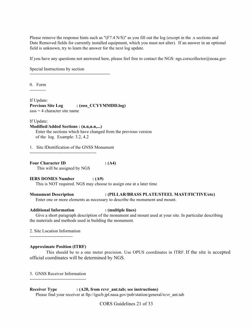
Please remove the response hints such as "(F7.4 N/S)" as you fill out the log (except in the .x sections andDate Removed fields for currently installed equipment, which you must not alter). If an answer in an optionalfield is unknown, try to learn the answer for the next log update.
If you have any questions not answered here, please feel free to contact the NGS: [email protected]
Special Instructions by section================================
0. Form-----------
If Update:Previous Site Log : (ssss_CCYYMMDD.log)ssss = 4 character site name
If Update:Modified/Added Sections : (n.n,n.n,...)
Enter the sections which have changed from the previous versionof the log. Example: 3.2, 4.2
1. Site IDentification of the GNSS Monument---------------------------------------------
Four Character ID : (A4) This will be assigned by NGS
IERS DOMES Number : (A9)This is NOT required. NGS may choose to assign one at a later time
Monument Description : (PILLAR/BRASS PLATE/STEEL MAST/FICTIVE/etc)Enter one or more elements as necessary to describe the monument and mount.
Additional Information : (multiple lines)Give a short paragraph description of the monument and mount used at your site. In particular describing
the materials and methods used in building the monument.
2. Site Location Information-----------------------------
Approximate Position (ITRF) This should be to a one meter precision. Use OPUS coordinates in ITRF. If the site is accepted
official coordinates will be determined by NGS.
3. GNSS Receiver Information--------------------------------------
Receiver Type : (A20, from rcvr_ant.tab; see instructions)Please find your receiver at ftp://igscb.jpl.nasa.gov/pub/station/general/rcvr_ant.tab
CORS Guidelines 22 of 33
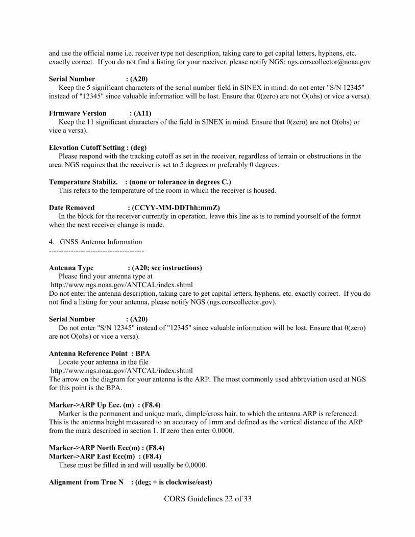
and use the official name i.e. receiver type not description, taking care to get capital letters, hyphens, etc.exactly correct. If you do not find a listing for your receiver, please notify NGS: [email protected]
Serial Number : (A20)Keep the 5 significant characters of the serial number field in SINEX in mind: do not enter "S/N 12345"
instead of "12345" since valuable information will be lost. Ensure that 0(zero) are not O(ohs) or vice a versa).
Firmware Version : (A11)Keep the 11 significant characters of the field in SINEX in mind. Ensure that 0(zero) are not O(ohs) or
vice a versa).
Elevation Cutoff Setting : (deg)Please respond with the tracking cutoff as set in the receiver, regardless of terrain or obstructions in the
area. NGS requires that the receiver is set to 5 degrees or preferably 0 degrees.
Temperature Stabiliz. : (none or tolerance in degrees C.)This refers to the temperature of the room in which the receiver is housed.
Date Removed : (CCYY-MM-DDThh:mmZ)In the block for the receiver currently in operation, leave this line as is to remind yourself of the format
when the next receiver change is made.
4. GNSS Antenna Information---------------------------------------
Antenna Type : (A20; see instructions)Please find your antenna type at
http://www.ngs.noaa.gov/ANTCAL/index.shtmlDo not enter the antenna description, taking care to get capital letters, hyphens, etc. exactly correct. If you donot find a listing for your antenna, please notify NGS (ngs.corscollector.gov).
Serial Number : (A20) Do not enter "S/N 12345" instead of "12345" since valuable information will be lost. Ensure that 0(zero)are not O(ohs) or vice a versa).
Antenna Reference Point : BPALocate your antenna in the file
http://www.ngs.noaa.gov/ANTCAL/index.shtmlThe arrow on the diagram for your antenna is the ARP. The most commonly used abbreviation used at NGSfor this point is the BPA.
Marker->ARP Up Ecc. (m) : (F8.4)Marker is the permanent and unique mark, dimple/cross hair, to which the antenna ARP is referenced.
This is the antenna height measured to an accuracy of 1mm and defined as the vertical distance of the ARPfrom the mark described in section 1. If zero then enter 0.0000.
Marker->ARP North Ecc(m) : (F8.4)Marker->ARP East Ecc(m) : (F8.4)
These must be filled in and will usually be 0.0000.
Alignment from True N : (deg; + is clockwise/east)
CORS Guidelines 23 of 33
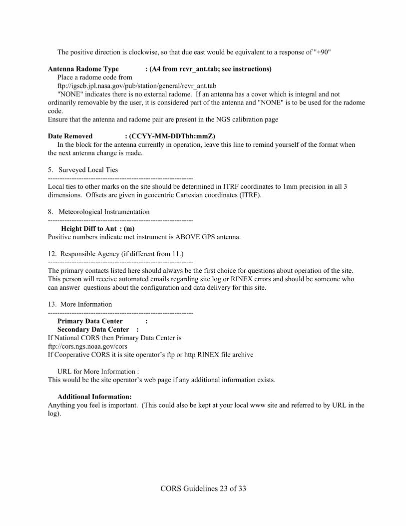
The positive direction is clockwise, so that due east would be equivalent to a response of "+90"
Antenna Radome Type : (A4 from rcvr_ant.tab; see instructions)Place a radome code fromftp://igscb.jpl.nasa.gov/pub/station/general/rcvr_ant.tab"NONE" indicates there is no external radome. If an antenna has a cover which is integral and not
ordinarily removable by the user, it is considered part of the antenna and "NONE" is to be used for the radomecode.Ensure that the antenna and radome pair are present in the NGS calibration page
Date Removed : (CCYY-MM-DDThh:mmZ)In the block for the antenna currently in operation, leave this line to remind yourself of the format when
the next antenna change is made.
5. Surveyed Local Ties-------------------------------------------------------------Local ties to other marks on the site should be determined in ITRF coordinates to 1mm precision in all 3dimensions. Offsets are given in geocentric Cartesian coordinates (ITRF).
8. Meteorological Instrumentation-------------------------------------------------------------
Height Diff to Ant : (m)Positive numbers indicate met instrument is ABOVE GPS antenna.
12. Responsible Agency (if different from 11.)-------------------------------------------------------------The primary contacts listed here should always be the first choice for questions about operation of the site.This person will receive automated emails regarding site log or RINEX errors and should be someone whocan answer questions about the configuration and data delivery for this site.
13. More Information-------------------------------------------------------------
Primary Data Center :Secondary Data Center :
If National CORS then Primary Data Center isftp://cors.ngs.noaa.gov/corsIf Cooperative CORS it is site operator’s ftp or http RINEX file archive
URL for More Information :This would be the site operator’s web page if any additional information exists.
Additional Information:Anything you feel is important. (This could also be kept at your local www site and referred to by URL in thelog).
CORS Guidelines 24 of 33
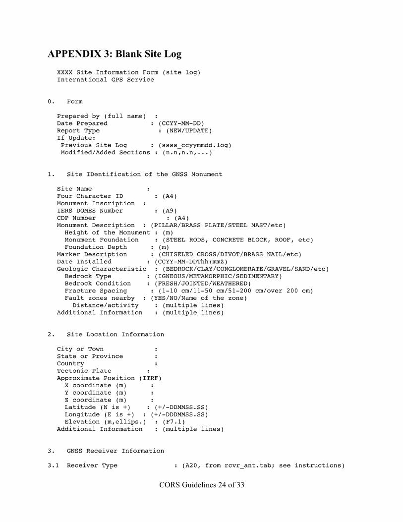
APPENDIX 3: Blank Site LogXXXX Site Information Form (site log)International GPS Service
0. Form
Prepared by (full name) :Date Prepared : (CCYY-MM-DD)Report Type : (NEW/UPDATE)If Update: Previous Site Log : (ssss_ccyymmdd.log) Modified/Added Sections : (n.n,n.n,...)
1. Site IDentification of the GNSS Monument
Site Name :Four Character ID : (A4)Monument Inscription :IERS DOMES Number : (A9)CDP Number : (A4)Monument Description : (PILLAR/BRASS PLATE/STEEL MAST/etc) Height of the Monument : (m) Monument Foundation : (STEEL RODS, CONCRETE BLOCK, ROOF, etc) Foundation Depth : (m)Marker Description : (CHISELED CROSS/DIVOT/BRASS NAIL/etc)Date Installed : (CCYY-MM-DDThh:mmZ)Geologic Characteristic : (BEDROCK/CLAY/CONGLOMERATE/GRAVEL/SAND/etc) Bedrock Type : (IGNEOUS/METAMORPHIC/SEDIMENTARY) Bedrock Condition : (FRESH/JOINTED/WEATHERED) Fracture Spacing : (1-10 cm/11-50 cm/51-200 cm/over 200 cm) Fault zones nearby : (YES/NO/Name of the zone) Distance/activity : (multiple lines)Additional Information : (multiple lines)
2. Site Location Information
City or Town :State or Province :Country :Tectonic Plate :Approximate Position (ITRF) X coordinate (m) : Y coordinate (m) : Z coordinate (m) : Latitude (N is +) : (+/-DDMMSS.SS) Longitude (E is +) : (+/-DDDMMSS.SS) Elevation (m,ellips.) : (F7.1)Additional Information : (multiple lines)
3. GNSS Receiver Information
3.1 Receiver Type : (A20, from rcvr_ant.tab; see instructions)
CORS Guidelines 25 of 33
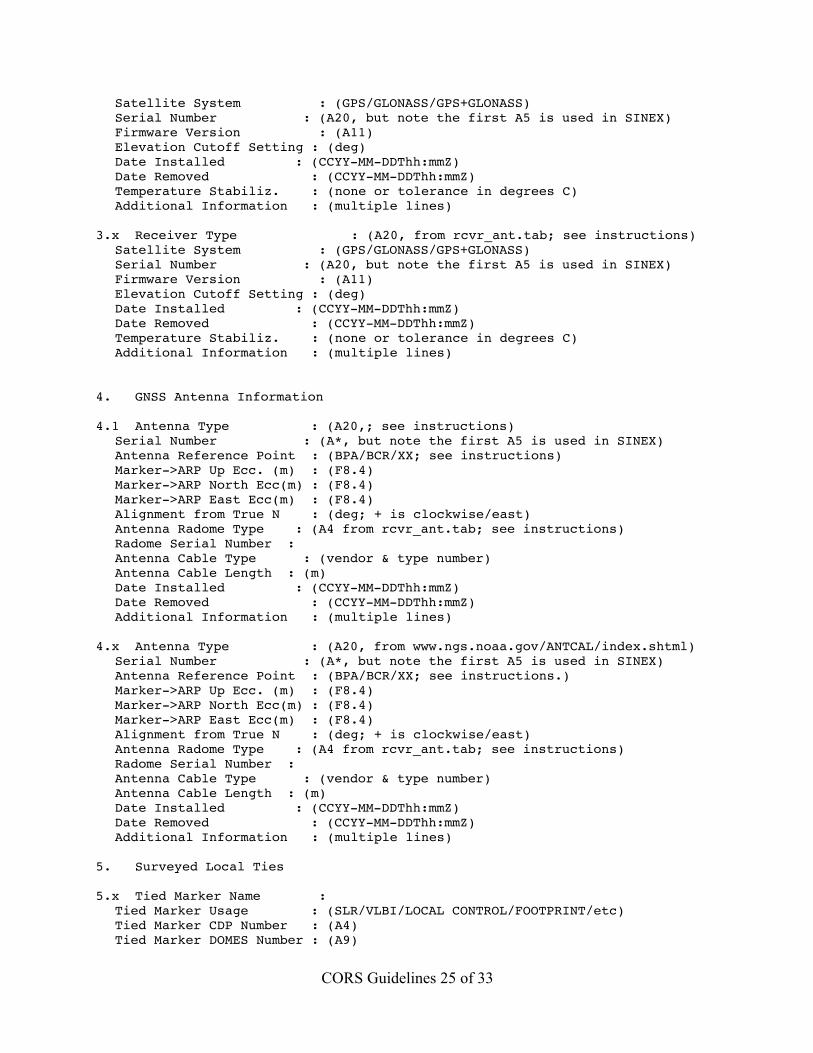
Satellite System : (GPS/GLONASS/GPS+GLONASS)Serial Number : (A20, but note the first A5 is used in SINEX)Firmware Version : (A11)Elevation Cutoff Setting : (deg)Date Installed : (CCYY-MM-DDThh:mmZ)Date Removed : (CCYY-MM-DDThh:mmZ)Temperature Stabiliz. : (none or tolerance in degrees C)Additional Information : (multiple lines)
3.x Receiver Type : (A20, from rcvr_ant.tab; see instructions)Satellite System : (GPS/GLONASS/GPS+GLONASS)Serial Number : (A20, but note the first A5 is used in SINEX)Firmware Version : (A11)Elevation Cutoff Setting : (deg)Date Installed : (CCYY-MM-DDThh:mmZ)Date Removed : (CCYY-MM-DDThh:mmZ)Temperature Stabiliz. : (none or tolerance in degrees C)Additional Information : (multiple lines)
4. GNSS Antenna Information
4.1 Antenna Type : (A20,; see instructions)Serial Number : (A*, but note the first A5 is used in SINEX)Antenna Reference Point : (BPA/BCR/XX; see instructions)Marker->ARP Up Ecc. (m) : (F8.4)Marker->ARP North Ecc(m) : (F8.4)Marker->ARP East Ecc(m) : (F8.4)Alignment from True N : (deg; + is clockwise/east)Antenna Radome Type : (A4 from rcvr_ant.tab; see instructions)Radome Serial Number :Antenna Cable Type : (vendor & type number)Antenna Cable Length : (m)Date Installed : (CCYY-MM-DDThh:mmZ)Date Removed : (CCYY-MM-DDThh:mmZ)Additional Information : (multiple lines)
4.x Antenna Type : (A20, from www.ngs.noaa.gov/ANTCAL/index.shtml)Serial Number : (A*, but note the first A5 is used in SINEX)Antenna Reference Point : (BPA/BCR/XX; see instructions.)Marker->ARP Up Ecc. (m) : (F8.4)Marker->ARP North Ecc(m) : (F8.4)Marker->ARP East Ecc(m) : (F8.4)Alignment from True N : (deg; + is clockwise/east)Antenna Radome Type : (A4 from rcvr_ant.tab; see instructions)Radome Serial Number :Antenna Cable Type : (vendor & type number)Antenna Cable Length : (m)Date Installed : (CCYY-MM-DDThh:mmZ)Date Removed : (CCYY-MM-DDThh:mmZ)Additional Information : (multiple lines)
5. Surveyed Local Ties
5.x Tied Marker Name :Tied Marker Usage : (SLR/VLBI/LOCAL CONTROL/FOOTPRINT/etc)Tied Marker CDP Number : (A4)Tied Marker DOMES Number : (A9)
CORS Guidelines 26 of 33
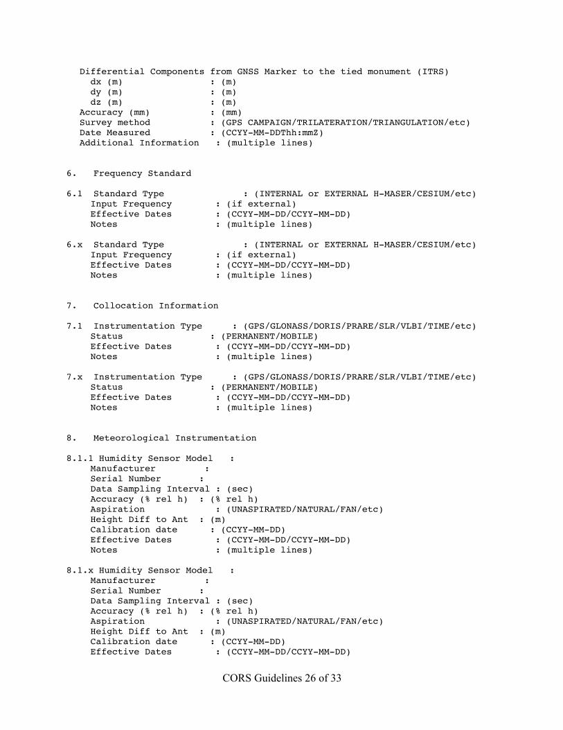
Differential Components from GNSS Marker to the tied monument (ITRS) dx (m) : (m) dy (m) : (m) dz (m) : (m)Accuracy (mm) : (mm)Survey method : (GPS CAMPAIGN/TRILATERATION/TRIANGULATION/etc)Date Measured : (CCYY-MM-DDThh:mmZ)Additional Information : (multiple lines)
6. Frequency Standard
6.1 Standard Type : (INTERNAL or EXTERNAL H-MASER/CESIUM/etc) Input Frequency : (if external) Effective Dates : (CCYY-MM-DD/CCYY-MM-DD) Notes : (multiple lines)
6.x Standard Type : (INTERNAL or EXTERNAL H-MASER/CESIUM/etc) Input Frequency : (if external) Effective Dates : (CCYY-MM-DD/CCYY-MM-DD) Notes : (multiple lines)
7. Collocation Information
7.1 Instrumentation Type : (GPS/GLONASS/DORIS/PRARE/SLR/VLBI/TIME/etc) Status : (PERMANENT/MOBILE) Effective Dates : (CCYY-MM-DD/CCYY-MM-DD) Notes : (multiple lines)
7.x Instrumentation Type : (GPS/GLONASS/DORIS/PRARE/SLR/VLBI/TIME/etc) Status : (PERMANENT/MOBILE) Effective Dates : (CCYY-MM-DD/CCYY-MM-DD) Notes : (multiple lines)
8. Meteorological Instrumentation
8.1.1 Humidity Sensor Model : Manufacturer : Serial Number : Data Sampling Interval : (sec) Accuracy (% rel h) : (% rel h) Aspiration : (UNASPIRATED/NATURAL/FAN/etc) Height Diff to Ant : (m) Calibration date : (CCYY-MM-DD) Effective Dates : (CCYY-MM-DD/CCYY-MM-DD) Notes : (multiple lines)
8.1.x Humidity Sensor Model : Manufacturer : Serial Number : Data Sampling Interval : (sec) Accuracy (% rel h) : (% rel h) Aspiration : (UNASPIRATED/NATURAL/FAN/etc) Height Diff to Ant : (m) Calibration date : (CCYY-MM-DD) Effective Dates : (CCYY-MM-DD/CCYY-MM-DD)
CORS Guidelines 27 of 33
Notes : (multiple lines)
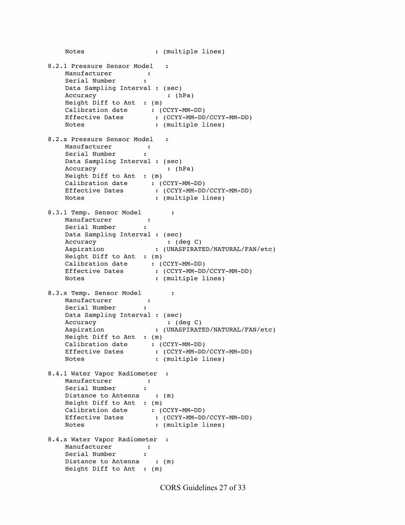
8.2.1 Pressure Sensor Model : Manufacturer : Serial Number : Data Sampling Interval : (sec) Accuracy : (hPa) Height Diff to Ant : (m) Calibration date : (CCYY-MM-DD) Effective Dates : (CCYY-MM-DD/CCYY-MM-DD) Notes : (multiple lines)
8.2.x Pressure Sensor Model : Manufacturer : Serial Number : Data Sampling Interval : (sec) Accuracy : (hPa) Height Diff to Ant : (m) Calibration date : (CCYY-MM-DD) Effective Dates : (CCYY-MM-DD/CCYY-MM-DD) Notes : (multiple lines)
8.3.1 Temp. Sensor Model : Manufacturer : Serial Number : Data Sampling Interval : (sec) Accuracy : (deg C) Aspiration : (UNASPIRATED/NATURAL/FAN/etc) Height Diff to Ant : (m) Calibration date : (CCYY-MM-DD) Effective Dates : (CCYY-MM-DD/CCYY-MM-DD) Notes : (multiple lines)
8.3.x Temp. Sensor Model : Manufacturer : Serial Number : Data Sampling Interval : (sec) Accuracy : (deg C) Aspiration : (UNASPIRATED/NATURAL/FAN/etc) Height Diff to Ant : (m) Calibration date : (CCYY-MM-DD) Effective Dates : (CCYY-MM-DD/CCYY-MM-DD) Notes : (multiple lines)
8.4.1 Water Vapor Radiometer : Manufacturer : Serial Number : Distance to Antenna : (m) Height Diff to Ant : (m) Calibration date : (CCYY-MM-DD) Effective Dates : (CCYY-MM-DD/CCYY-MM-DD) Notes : (multiple lines)
8.4.x Water Vapor Radiometer : Manufacturer : Serial Number : Distance to Antenna : (m) Height Diff to Ant : (m)
CORS Guidelines 28 of 33
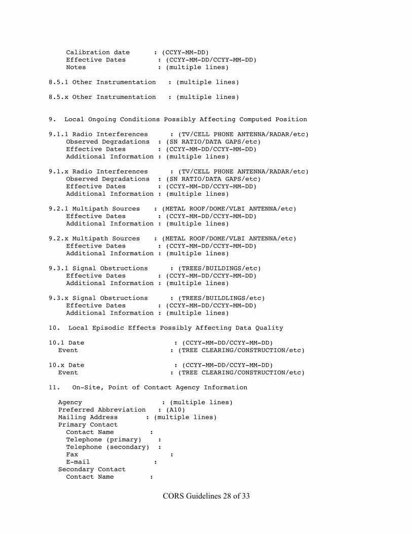
Calibration date : (CCYY-MM-DD) Effective Dates : (CCYY-MM-DD/CCYY-MM-DD) Notes : (multiple lines)
8.5.1 Other Instrumentation : (multiple lines)
8.5.x Other Instrumentation : (multiple lines)
9. Local Ongoing Conditions Possibly Affecting Computed Position
9.1.1 Radio Interferences : (TV/CELL PHONE ANTENNA/RADAR/etc) Observed Degradations : (SN RATIO/DATA GAPS/etc) Effective Dates : (CCYY-MM-DD/CCYY-MM-DD) Additional Information : (multiple lines)
9.1.x Radio Interferences : (TV/CELL PHONE ANTENNA/RADAR/etc) Observed Degradations : (SN RATIO/DATA GAPS/etc) Effective Dates : (CCYY-MM-DD/CCYY-MM-DD) Additional Information : (multiple lines)
9.2.1 Multipath Sources : (METAL ROOF/DOME/VLBI ANTENNA/etc) Effective Dates : (CCYY-MM-DD/CCYY-MM-DD) Additional Information : (multiple lines)
9.2.x Multipath Sources : (METAL ROOF/DOME/VLBI ANTENNA/etc) Effective Dates : (CCYY-MM-DD/CCYY-MM-DD) Additional Information : (multiple lines)
9.3.1 Signal Obstructions : (TREES/BUILDINGS/etc) Effective Dates : (CCYY-MM-DD/CCYY-MM-DD) Additional Information : (multiple lines)
9.3.x Signal Obstructions : (TREES/BUILDLINGS/etc) Effective Dates : (CCYY-MM-DD/CCYY-MM-DD) Additional Information : (multiple lines)
10. Local Episodic Effects Possibly Affecting Data Quality
10.1 Date : (CCYY-MM-DD/CCYY-MM-DD)Event : (TREE CLEARING/CONSTRUCTION/etc)
10.x Date : (CCYY-MM-DD/CCYY-MM-DD)Event : (TREE CLEARING/CONSTRUCTION/etc)
11. On-Site, Point of Contact Agency Information
Agency : (multiple lines)Preferred Abbreviation : (A10)Mailing Address : (multiple lines)Primary Contact Contact Name : Telephone (primary) : Telephone (secondary) : Fax : E-mail :Secondary Contact Contact Name :
CORS Guidelines 29 of 33
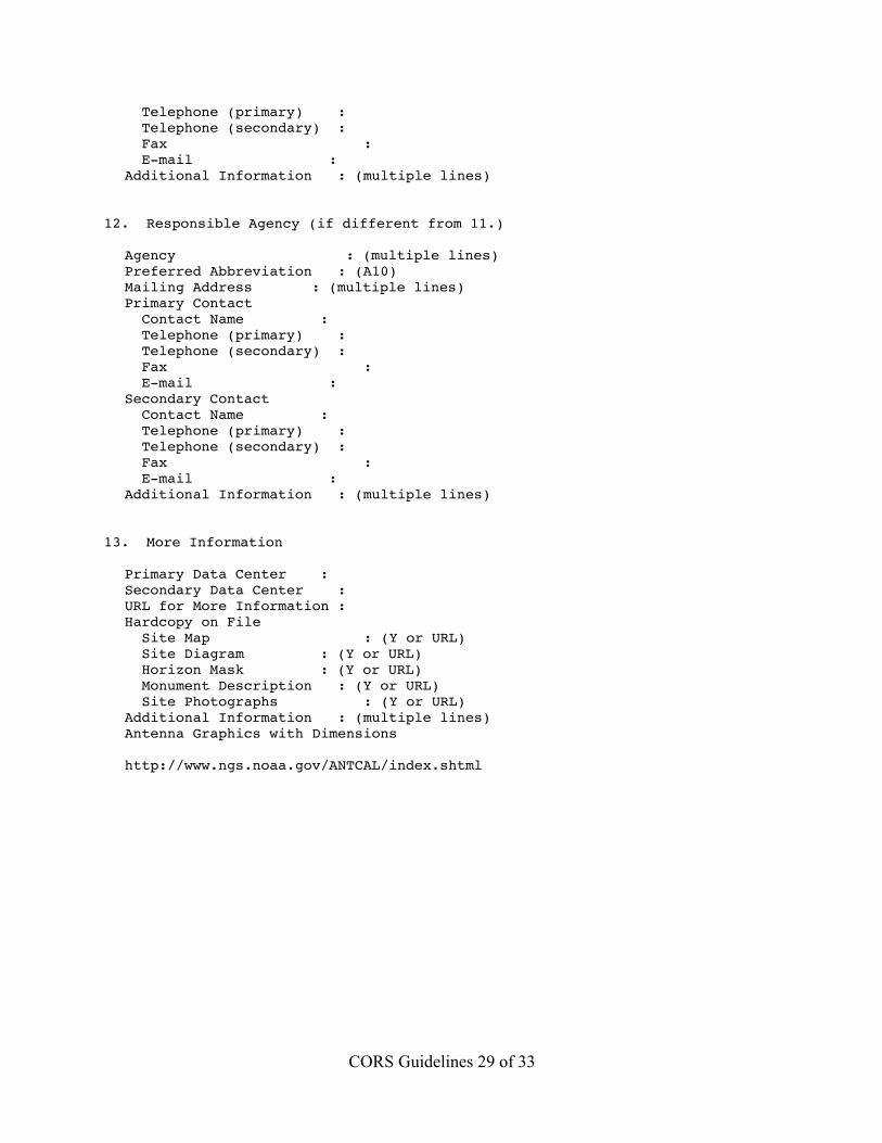
Telephone (primary) : Telephone (secondary) : Fax : E-mail :Additional Information : (multiple lines)
12. Responsible Agency (if different from 11.)
Agency : (multiple lines)Preferred Abbreviation : (A10)Mailing Address : (multiple lines)Primary Contact Contact Name : Telephone (primary) : Telephone (secondary) : Fax : E-mail :Secondary Contact Contact Name : Telephone (primary) : Telephone (secondary) : Fax : E-mail :Additional Information : (multiple lines)
13. More Information
Primary Data Center :Secondary Data Center :URL for More Information :Hardcopy on File Site Map : (Y or URL) Site Diagram : (Y or URL) Horizon Mask : (Y or URL) Monument Description : (Y or URL) Site Photographs : (Y or URL)Additional Information : (multiple lines)Antenna Graphics with Dimensions
http://www.ngs.noaa.gov/ANTCAL/index.shtml
CORS Guidelines 30 of 33
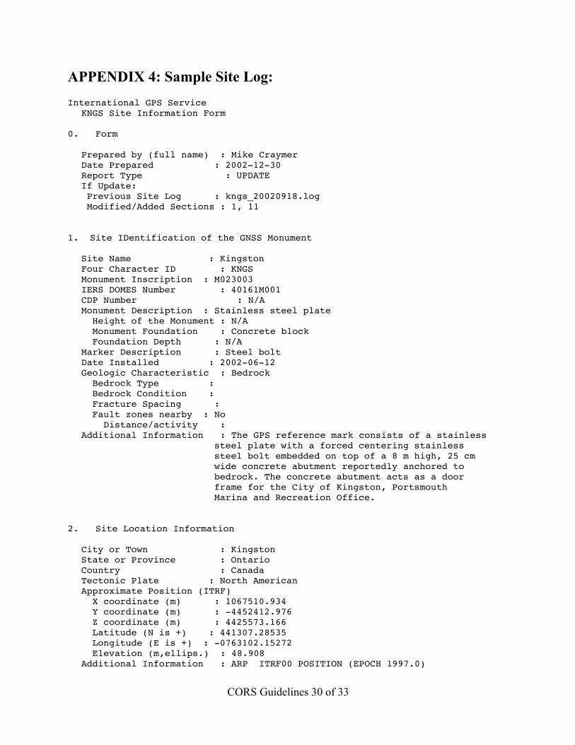
APPENDIX 4: Sample Site Log:International GPS Service
KNGS Site Information Form
0. Form
Prepared by (full name) : Mike CraymerDate Prepared : 2002-12-30Report Type : UPDATEIf Update: Previous Site Log : kngs_20020918.log Modified/Added Sections : 1, 11
1. Site IDentification of the GNSS Monument
Site Name : KingstonFour Character ID : KNGSMonument Inscription : M023003IERS DOMES Number : 40161M001CDP Number : N/AMonument Description : Stainless steel plate Height of the Monument : N/A Monument Foundation : Concrete block Foundation Depth : N/AMarker Description : Steel boltDate Installed : 2002-06-12Geologic Characteristic : Bedrock Bedrock Type : Bedrock Condition : Fracture Spacing : Fault zones nearby : No Distance/activity :Additional Information : The GPS reference mark consists of a stainless
steel plate with a forced centering stainless steel bolt embedded on top of a 8 m high, 25 cm wide concrete abutment reportedly anchored to bedrock. The concrete abutment acts as a door frame for the City of Kingston, Portsmouth Marina and Recreation Office.
2. Site Location Information
City or Town : KingstonState or Province : OntarioCountry : CanadaTectonic Plate : North AmericanApproximate Position (ITRF) X coordinate (m) : 1067510.934 Y coordinate (m) : -4452412.976 Z coordinate (m) : 4425573.166 Latitude (N is +) : 441307.28535 Longitude (E is +) : -0763102.15272 Elevation (m,ellips.) : 48.908Additional Information : ARP ITRF00 POSITION (EPOCH 1997.0)
CORS Guidelines 31 of 33
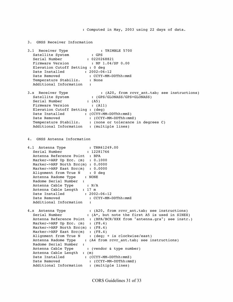
: Computed in May, 2003 using 22 days of data.
3. GNSS Receiver Information
3.1 Receiver Type : TRIMBLE 5700Satellite System : GPSSerial Number : 0220268821Firmware Version : NP 1.04/SP 0.00Elevation Cutoff Setting : 0 degDate Installed : 2002-06-12Date Removed : CCYY-MM-DDThh:mmZTemperature Stabiliz. : NoneAdditional Information :
3.x Receiver Type : (A20, from rcvr_ant.tab; see instructions)Satellite System : (GPS/GLONASS/GPS+GLONASS)Serial Number : (A5)Firmware Version : (A11)Elevation Cutoff Setting : (deg)Date Installed : (CCYY-MM-DDThh:mmZ)Date Removed : (CCYY-MM-DDThh:mmZ)Temperature Stabiliz. : (none or tolerance in degrees C)Additional Information : (multiple lines)
4. GNSS Antenna Information
4.1 Antenna Type : TRM41249.00Serial Number : 12281766Antenna Reference Point : BPAMarker->ARP Up Ecc. (m) : 0.1000Marker->ARP North Ecc(m) : 0.0000Marker->ARP East Ecc(m) : 0.0000Alignment from True N : 0 degAntenna Radome Type : NONERadome Serial Number :Antenna Cable Type : N/AAntenna Cable Length : 17 mDate Installed : 2002-06-12Date Removed : CCYY-MM-DDThh:mmZAdditional Information :
4.x Antenna Type : (A20, from rcvr_ant.tab; see instructions)Serial Number : (A*, but note the first A5 is used in SINEX)Antenna Reference Point : (BPA/BCR/XXX from "antenna.gra"; see instr.)Marker->ARP Up Ecc. (m) : (F8.4)Marker->ARP North Ecc(m) : (F8.4)Marker->ARP East Ecc(m) : (F8.4)Alignment from True N : (deg; + is clockwise/east)Antenna Radome Type : (A4 from rcvr_ant.tab; see instructions)Radome Serial Number :Antenna Cable Type : (vendor & type number)Antenna Cable Length : (m)Date Installed : (CCYY-MM-DDThh:mmZ)Date Removed : (CCYY-MM-DDThh:mmZ)Additional Information : (multiple lines)
CORS Guidelines 32 of 33
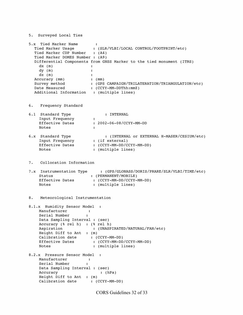
5. Surveyed Local Ties
5.x Tied Marker Name :Tied Marker Usage : (SLR/VLBI/LOCAL CONTROL/FOOTPRINT/etc)Tied Marker CDP Number : (A4)Tied Marker DOMES Number : (A9)Differential Components from GNSS Marker to the tied monument (ITRS) dx (m) : dy (m) : dz (m) :Accuracy (mm) : (mm)Survey method : (GPS CAMPAIGN/TRILATERATION/TRIANGULATION/etc)Date Measured : (CCYY-MM-DDThh:mmZ)Additional Information : (multiple lines)
6. Frequency Standard
6.1 Standard Type : INTERNAL Input Frequency : Effective Dates : 2002-06-08/CCYY-MM-DD Notes :
6.x Standard Type : (INTERNAL or EXTERNAL H-MASER/CESIUM/etc) Input Frequency : (if external) Effective Dates : (CCYY-MM-DD/CCYY-MM-DD) Notes : (multiple lines)
7. Collocation Information
7.x Instrumentation Type : (GPS/GLONASS/DORIS/PRARE/SLR/VLBI/TIME/etc) Status : (PERMANENT/MOBILE) Effective Dates : (CCYY-MM-DD/CCYY-MM-DD) Notes : (multiple lines)
8. Meteorological Instrumentation
8.1.x Humidity Sensor Model : Manufacturer : Serial Number : Data Sampling Interval : (sec) Accuracy (% rel h) : (% rel h) Aspiration : (UNASPIRATED/NATURAL/FAN/etc) Height Diff to Ant : (m) Calibration date : (CCYY-MM-DD) Effective Dates : (CCYY-MM-DD/CCYY-MM-DD) Notes : (multiple lines)
8.2.x Pressure Sensor Model : Manufacturer : Serial Number : Data Sampling Interval : (sec) Accuracy : (hPa) Height Diff to Ant : (m) Calibration date : (CCYY-MM-DD)
CORS Guidelines 33 of 33
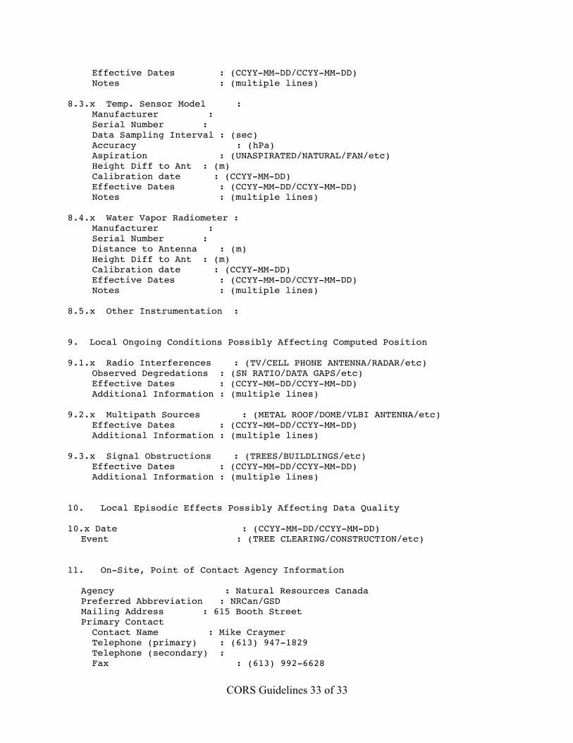
Effective Dates : (CCYY-MM-DD/CCYY-MM-DD) Notes : (multiple lines)
8.3.x Temp. Sensor Model : Manufacturer : Serial Number : Data Sampling Interval : (sec) Accuracy : (hPa) Aspiration : (UNASPIRATED/NATURAL/FAN/etc) Height Diff to Ant : (m) Calibration date : (CCYY-MM-DD) Effective Dates : (CCYY-MM-DD/CCYY-MM-DD) Notes : (multiple lines)
8.4.x Water Vapor Radiometer : Manufacturer : Serial Number : Distance to Antenna : (m) Height Diff to Ant : (m) Calibration date : (CCYY-MM-DD) Effective Dates : (CCYY-MM-DD/CCYY-MM-DD) Notes : (multiple lines)
8.5.x Other Instrumentation :
9. Local Ongoing Conditions Possibly Affecting Computed Position
9.1.x Radio Interferences : (TV/CELL PHONE ANTENNA/RADAR/etc) Observed Degredations : (SN RATIO/DATA GAPS/etc) Effective Dates : (CCYY-MM-DD/CCYY-MM-DD) Additional Information : (multiple lines)
9.2.x Multipath Sources : (METAL ROOF/DOME/VLBI ANTENNA/etc) Effective Dates : (CCYY-MM-DD/CCYY-MM-DD) Additional Information : (multiple lines)
9.3.x Signal Obstructions : (TREES/BUILDLINGS/etc) Effective Dates : (CCYY-MM-DD/CCYY-MM-DD) Additional Information : (multiple lines)
10. Local Episodic Effects Possibly Affecting Data Quality
10.x Date : (CCYY-MM-DD/CCYY-MM-DD)Event : (TREE CLEARING/CONSTRUCTION/etc)
11. On-Site, Point of Contact Agency Information
Agency : Natural Resources CanadaPreferred Abbreviation : NRCan/GSDMailing Address : 615 Booth StreetPrimary Contact Contact Name : Mike Craymer Telephone (primary) : (613) 947-1829 Telephone (secondary) : Fax : (613) 992-6628
CORS Guidelines 34 of 33
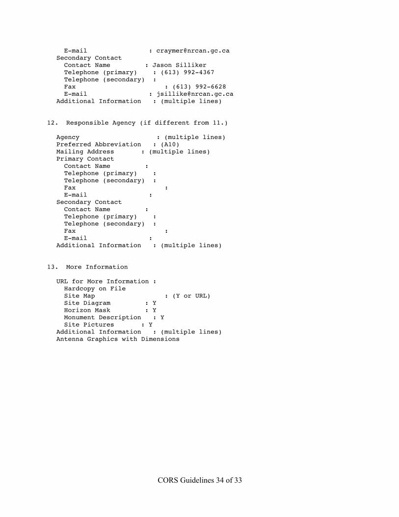
E-mail : [email protected] Contact Contact Name : Jason Silliker Telephone (primary) : (613) 992-4367 Telephone (secondary) : Fax : (613) 992-6628 E-mail : [email protected] Information : (multiple lines)
12. Responsible Agency (if different from 11.)
Agency : (multiple lines)Preferred Abbreviation : (A10)Mailing Address : (multiple lines)Primary Contact Contact Name : Telephone (primary) : Telephone (secondary) : Fax : E-mail :Secondary Contact Contact Name : Telephone (primary) : Telephone (secondary) : Fax : E-mail :Additional Information : (multiple lines)
13. More Information
URL for More Information : Hardcopy on File Site Map : (Y or URL) Site Diagram : Y Horizon Mask : Y Monument Description : Y Site Pictures : YAdditional Information : (multiple lines)Antenna Graphics with Dimensions