Guidelines for Implementation of an Advanced Outage ...
88
The INL is a U.S. Department of Energy National Laboratory operated by Battelle Energy Alliance INL/EXT-14-33182 Rev. 0 Guidelines for Implementation of an Advanced Outage Control Center to Improve Outage Coordination, Problem Resolution, and Outage Risk Management Shawn W. St. Germain Ronald K. Farris April M. Whaley Heather D. Medema David I. Gertman September 2014
Transcript of Guidelines for Implementation of an Advanced Outage ...
The INL is a U.S. Department of Energy National Laboratory operated by Battelle Energy Alliance
INL/EXT-14-33182 Rev. 0
Guidelines for Implementation of an Advanced Outage Control Center to Improve Outage Coordination, Problem Resolution, and Outage Risk Management
Shawn W. St. Germain Ronald K. Farris April M. Whaley Heather D. Medema David I. Gertman September 2014

DISCLAIMER This information was prepared as an account of work sponsored by an
agency of the U.S. Government. Neither the U.S. Government nor any agency thereof, nor any of their employees, makes any warranty, expressed or implied, or assumes any legal liability or responsibility for the accuracy, completeness, or usefulness, of any information, apparatus, product, or process disclosed, or represents that its use would not infringe privately owned rights. References herein to any specific commercial product, process, or service by trade name, trade mark, manufacturer, or otherwise, does not necessarily constitute or imply its endorsement, recommendation, or favoring by the U.S. Government or any agency thereof. The views and opinions of authors expressed herein do not necessarily state or reflect those of the U.S. Government or any agency thereof.
ii
INL/EXT-14-33182 Rev. 0
Guidelines for Implementation of an Advanced Outage Control Center to Improve Outage Coordination,
Problem Resolution, and Outage Risk Management
Shawn St. Germain Ronald Farris
April M. Whaley Heather Medema David Gertman
September 2014
Idaho National Laboratory Idaho Falls, Idaho 83415
http://www.inl.gov
Prepared under Work Package L-12N060305 Prepared for the
U.S. Department of Energy Office of Nuclear Energy
Under DOE Idaho Operations Office Contract DE-AC07-05ID14517

iii
iv
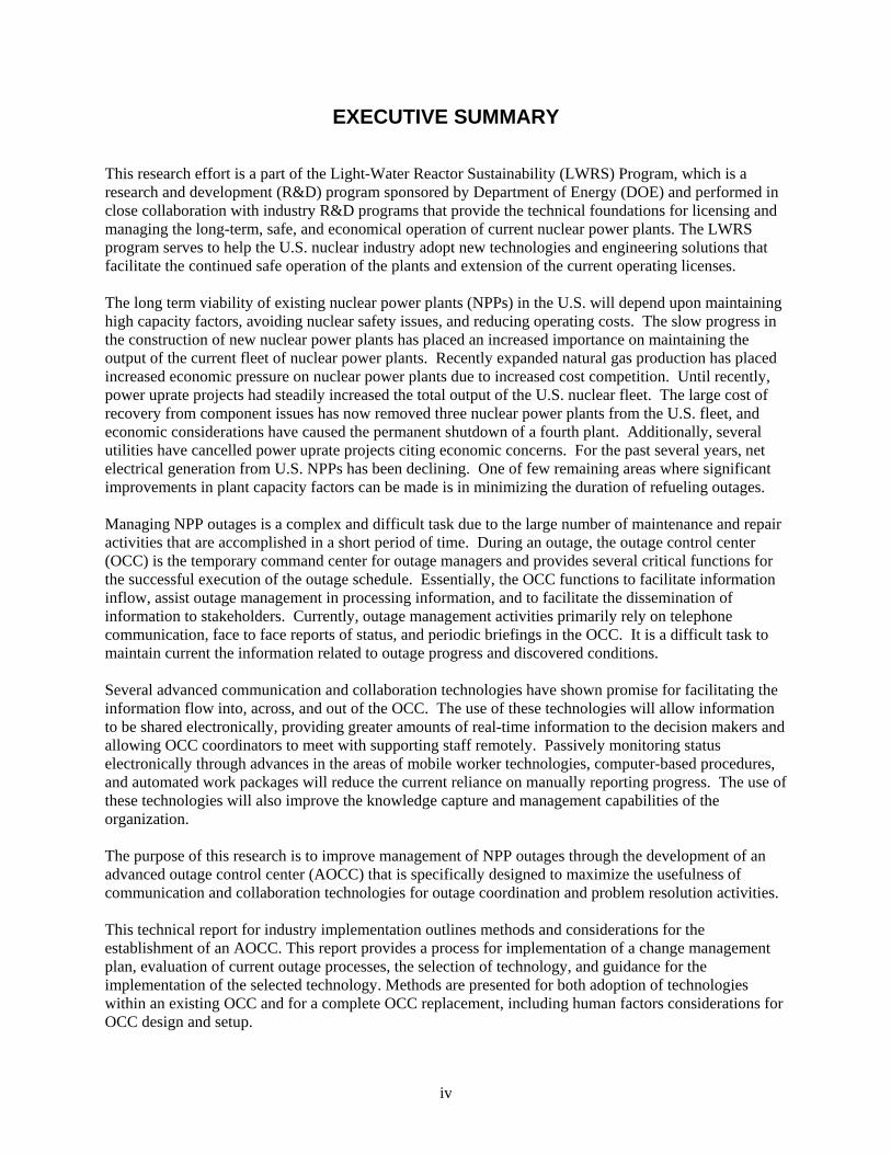
EXECUTIVE SUMMARY
This research effort is a part of the Light-Water Reactor Sustainability (LWRS) Program, which is a research and development (R&D) program sponsored by Department of Energy (DOE) and performed in close collaboration with industry R&D programs that provide the technical foundations for licensing and managing the long-term, safe, and economical operation of current nuclear power plants. The LWRS program serves to help the U.S. nuclear industry adopt new technologies and engineering solutions that facilitate the continued safe operation of the plants and extension of the current operating licenses. The long term viability of existing nuclear power plants (NPPs) in the U.S. will depend upon maintaining high capacity factors, avoiding nuclear safety issues, and reducing operating costs. The slow progress in the construction of new nuclear power plants has placed an increased importance on maintaining the output of the current fleet of nuclear power plants. Recently expanded natural gas production has placed increased economic pressure on nuclear power plants due to increased cost competition. Until recently, power uprate projects had steadily increased the total output of the U.S. nuclear fleet. The large cost of recovery from component issues has now removed three nuclear power plants from the U.S. fleet, and economic considerations have caused the permanent shutdown of a fourth plant. Additionally, several utilities have cancelled power uprate projects citing economic concerns. For the past several years, net electrical generation from U.S. NPPs has been declining. One of few remaining areas where significant improvements in plant capacity factors can be made is in minimizing the duration of refueling outages. Managing NPP outages is a complex and difficult task due to the large number of maintenance and repair activities that are accomplished in a short period of time. During an outage, the outage control center (OCC) is the temporary command center for outage managers and provides several critical functions for the successful execution of the outage schedule. Essentially, the OCC functions to facilitate information inflow, assist outage management in processing information, and to facilitate the dissemination of information to stakeholders. Currently, outage management activities primarily rely on telephone communication, face to face reports of status, and periodic briefings in the OCC. It is a difficult task to maintain current the information related to outage progress and discovered conditions. Several advanced communication and collaboration technologies have shown promise for facilitating the information flow into, across, and out of the OCC. The use of these technologies will allow information to be shared electronically, providing greater amounts of real-time information to the decision makers and allowing OCC coordinators to meet with supporting staff remotely. Passively monitoring status electronically through advances in the areas of mobile worker technologies, computer-based procedures, and automated work packages will reduce the current reliance on manually reporting progress. The use of these technologies will also improve the knowledge capture and management capabilities of the organization. The purpose of this research is to improve management of NPP outages through the development of an advanced outage control center (AOCC) that is specifically designed to maximize the usefulness of communication and collaboration technologies for outage coordination and problem resolution activities. This technical report for industry implementation outlines methods and considerations for the establishment of an AOCC. This report provides a process for implementation of a change management plan, evaluation of current outage processes, the selection of technology, and guidance for the implementation of the selected technology. Methods are presented for both adoption of technologies within an existing OCC and for a complete OCC replacement, including human factors considerations for OCC design and setup.
v
ACKNOWLEDGMENTS
The Advanced Outage Control Center research team would like to acknowledge the efforts of the
following individuals and organizations that made this research possible.
Michael Grigsby, Carlos Williams and members of the Arizona Public Services Palo Verde Nuclear Generating Station staff for hosting the research activities;
Michael Hildebrandt and the staff of the OECD Halden Reactor Project;
Ken Thomas, Dr. Bruce Hallbert for technical review of the research methodology and report;
Jacques Hugo for creation of the 3D AOCC concept models.
vi
CONTENTS
Executive Summary ..................................................................................................... iv
Acknowledgments ......................................................................................................... v
CONTENTS ................................................................................................................... vi
FIGURES ..................................................................................................................... viii
TABLES ....................................................................................................................... viii
ACRONYMS .................................................................................................................. ix
1 Introduction ............................................................................................................. 1 1.1 AOCC Vision ................................................................................................................. 1 1.2 Implementation Overview ............................................................................................ 2
2 Establish a Change Management Plan ................................................................. 4 2.1 Method ........................................................................................................................... 4 2.2 Roles and Responsibilities .......................................................................................... 4 2.3 Change Management Process .................................................................................... 5
2.3.1 Establish Priorities For Outage Process Improvement Initiative .............................. 5 2.3.2 Define the Gap ........................................................................................................ 6 2.3.3 Obtain Sponsorship ................................................................................................. 6 2.3.4 Effectively Communicate the Upcoming Changes .................................................. 7 2.3.5 Reinforce Desired Behaviors Consistent with Metrics ............................................. 7 2.3.6 Continually Monitor Scope and Definition of Plan ................................................... 7
2.4 Documentation ............................................................................................................. 8
3 Evaluate Current Outage Processes ..................................................................... 9 3.1 Overview of OCC Functions ........................................................................................ 9 3.2 Overview of Function Analysis (FA) in Support of Technology Deployment at NPPs 10
3.2.1 Requirements gathering in support of FA. ............................................................. 10 3.2.2 Model for allocating AOCC functions. ................................................................... 11
3.3 Communication Paths ................................................................................................ 12 3.3.1 Identification of Key Support Groups ..................................................................... 12 3.3.2 Map of Communications Between Support Groups and OCC .............................. 13
3.4 OCC Outage Functions .............................................................................................. 16 3.5 Function Analysis Results ......................................................................................... 17
4 Select Desired Technologies for Implementation .............................................. 19 4.1 Advanced Outage Functions ..................................................................................... 19 4.2 Available Technologies .............................................................................................. 20
4.2.1 Touch Enabled Interactive Displays ...................................................................... 20 4.2.2 Collaboration Software .......................................................................................... 22 4.2.3 Mobile Worker Devices ......................................................................................... 25 4.2.4 Remote Cameras .................................................................................................. 25
vii
4.2.5 Computer based procedures/Automated Work Packages .................................... 26 4.2.6 Alternative Voice Communication ......................................................................... 26 4.2.7 Plant Wide Wireless Networks .............................................................................. 26
4.3 Functions vs. Available Technologies ..................................................................... 26
5 Technology Implementation ................................................................................ 28 5.1 Stepwise Technology Deployment ........................................................................... 28 5.2 Development of the Technology Deployment Plan ................................................. 28
5.2.1 Risk vs. benefit ...................................................................................................... 28 5.2.2 Considerations: Culture, Current State, Cost, Cost Savings, and Others ............. 30
5.3 Implementation of Technology Upgrades ................................................................ 31 5.3.1 Change Management Plan .................................................................................... 31 5.3.2 Update Processes ................................................................................................. 32 5.3.3 Technology Deployment ........................................................................................ 32 5.3.4 Training ................................................................................................................. 32 5.3.5 Provide Early Technical Support ........................................................................... 32
5.4 Performance Evaluation ............................................................................................ 32
6 New Physical OCC ................................................................................................ 33 6.1 Human Factors Considerations ................................................................................ 33
6.1.1 Generic Principles for the Design of Control Centers ............................................ 34 6.1.2 Principles for the Arrangement and Layout of the Control Room/Suite ................. 41 6.1.3 Control Room Layout (ISO 11064-3:1999) ............................................................ 47 6.1.4 Ergonomic Principles for Workstations .................................................................. 49 6.1.5 Design Principles for Operator Workload .............................................................. 49
6.2 Staffing ........................................................................................................................ 51 6.3 A Recommended AOCC Layout ................................................................................ 51
7 Conclusions .......................................................................................................... 54
8 References ............................................................................................................ 55
APPENDICES ............................................................................................................... 57
Appendix A: Palo Verde Case Study ......................................................................... 58
Appendix B: Plant Farley Case Study ....................................................................... 61
Appendix C: Advanced Test Reactor Case Study .................................................... 62
Appendix D: Data Collection Forms .......................................................................... 63 Outage Communication Analysis Form .............................................................................. 67
Appendix E: Change Management Checklist Guide ................................................ 69 Build and implement a communication plan specifically for the outage improvement initiative to determine the effectiveness of communications. .......................................... 71
Appendix F: Strategic Change Management Checklist ........................................... 72
Appendix G: Tactical Change Management Checklist ............................................. 74
viii
Appendix H: Communication Plan (Template) ......................................................... 76
FIGURES
Figure 1. Overview of the AOCC Implementation Strategy .......................................................... 3 Figure 2. Model of Function Allocation (Hugo et al, 2014). ......................................................... 12 Figure 3. Communication Analysis Form (Front). ...................................................................... 13 Figure 4. Communication Analysis Form (Back). ....................................................................... 14 Figure 5. Outage Communication Form (Front). ........................................................................ 15 Figure 6. Outage Communication Form (Back). ........................................................................ 15 Figure 7. Communication Link Analysis showing key outage communication paths. ................ 16 Figure 8. Task Observation Form. ............................................................................................. 17 Figure 9. Typical Existing Condition. .......................................................................................... 18 Figure 10. Proposed Future Condition. ...................................................................................... 18 Figure 11. Video wall installed at Palo Verde. ........................................................................... 21 Figure 12. Use of a touch enabled interactive display to support emergent issues response. .. 22 Figure 13. CSCW Matrix (Johansen, 1988). .............................................................................. 23 Figure 14. Standard Issues Package Example (MS OneNote). ................................................. 24 Figure 15. Iterative ergonomic design process for control centers (ISO 11064-1:2000, p. 7).... 37 Figure 16. ISO distinction between a control room, a control suite, and a control center (ISO
11064-3:1999, p. 4). ............................................................................................................ 42 Figure 17. A recommended AOCC layout. ................................................................................ 51 Figure 18. Reverse view of the AOCC recommended layout. ................................................... 52 Figure 19. Palo Verde Research Plan. ...................................................................................... 58
TABLES
Table 1. Change Management Roles and Responsibilities. ........................................................ 4 Table 2. AOCC Functions and Features Mapped to Enabling Technologies. ........................... 27 Table 3. Example design solutions for avoiding the impairing effects of mental workload (ISO
11075-2:1996, p 11). ........................................................................................................... 50
ix
ACRONYMS
AOCC Advanced Outage Control Center
ATR Advanced Test Reactor
AWP Automated Work Packages
CBP Computer-Based Procedures
COTS Commercial Off-The-Shelf Technology
CRADA Cooperative Research and Development Agreement
DOE Department of Energy
EPRI Electric Power Research Institute
EWP Electronic Work Packages
HFE Human Factors Engineering
HMI Human-Machine Interface
HSI Human-Systems Interface
HSSL Human Systems Simulation Laboratory
HU Human Performance
ICC Information & Communication Center
II&C Instrumentation, Information, and Control
INL Idaho National Laboratory
INPO Institute of Nuclear Power Operations
IRT Issues Response Team
IT Information Technology
LWRS Light Water Reactor Sustainability
MCR Main Control Room
NEO Nuclear Equipment Operator
NPP Nuclear Power Plant
x
OCC Outage Control Center
OE Operating Experience
PBP Paper-Based Procedure
PSC Plant Status Control
QC Quality Control
R&D Research and Development
RFID Radio-Frequency Identification
SIG Special Interest Group
SME Subject Matter Expert
SOD Shift Outage Director
SOM Shift Outage Manager
1
1 INTRODUCTION
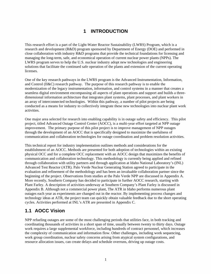
This research effort is a part of the Light-Water Reactor Sustainability (LWRS) Program, which is a research and development (R&D) program sponsored by Department of Energy (DOE) and performed in close collaboration with industry R&D programs that provide the technical foundations for licensing and managing the long-term, safe, and economical operation of current nuclear power plants (NPPs). The LWRS program serves to help the U.S. nuclear industry adopt new technologies and engineering solutions that facilitate the continued safe operation of the plants and extension of the current operating licenses. One of the key research pathways in the LWRS program is the Advanced Instrumentation, Information, and Control (II&C) research pathway. The purpose of this research pathway is to enable the modernization of the legacy instrumentation, information, and control systems in a manner that creates a seamless digital environment encompassing all aspects of plant operations and support and builds a three-dimensional information architecture that integrates plant systems, plant processes, and plant workers in an array of interconnected technologies. Within this pathway, a number of pilot projects are being conducted as a means for industry to collectively integrate these new technologies into nuclear plant work activities. One major area selected for research into enabling capability is in outage safety and efficiency. This pilot project, titled Advanced Outage Control Center (AOCC), is a multi-year effort targeted at NPP outage improvement. The primary purpose of this pilot project is to improve management of NPP outages through the development of an AOCC that is specifically designed to maximize the usefulness of communication and collaboration technologies for outage coordination and problem resolution activities. This technical report for industry implementation outlines methods and considerations for the establishment of an AOCC. Methods are presented for both adoption of technologies within an existing physical OCC and for a complete OCC replacement with an AOCC design that maximizes the benefits of communication and collaboration technology. This methodology is currently being applied and refined through collaboration with utility partners and through application at Idaho National Laboratory’s (INL) Advanced Test Reactor (ATR). Palo Verde Nuclear Generating Station agreed to participate in the evaluation and refinement of the methodology and has been an invaluable collaboration partner since the beginning of the project. Observations from studies at the Palo Verde NPP are discussed in Appendix A. More recently, Southern Company has decided to participate in further AOCC research, starting with Plant Farley. A description of activities underway at Southern Company’s Plant Farley is discussed in Appendix B. Although not a commercial power plant, The ATR in Idaho performs numerous plant outages each year as experiments are changed out in the reactor. By implementing process changes and technology ideas at ATR, the project team can quickly obtain valuable feedback due to the short operating cycles. Activities performed at INL’s ATR are presented in Appendix C.
1.1 AOCC Vision
NPP refueling outages are some of the most challenging periods that utilities face, in both tracking and coordinating thousands of activities in a short span of time, usually between twenty to thirty days. Outage work requires a large supplemental workforce, including hundreds of contract personnel, which increases the complexity of communication and information flow. Other challenges, including work sequencing, work group coordination, nuclear safety concerns arising from atypical system configurations, and resource allocation issues, can create delays and schedule overruns, driving up outage costs.
2
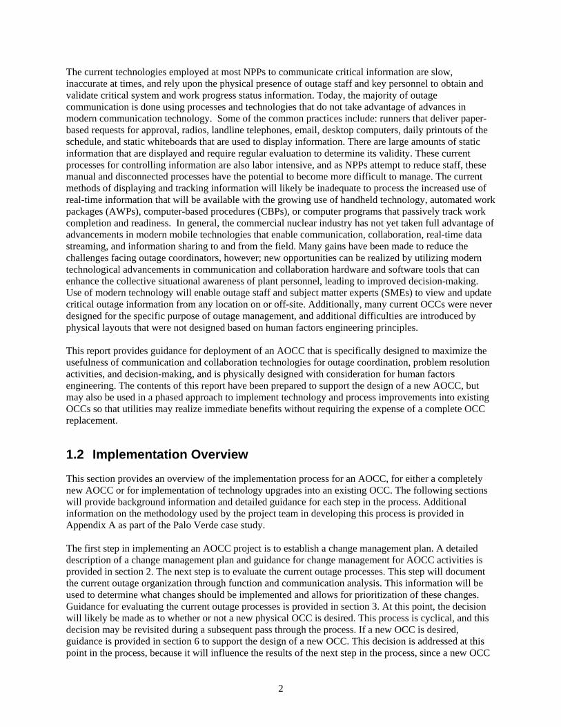
The current technologies employed at most NPPs to communicate critical information are slow, inaccurate at times, and rely upon the physical presence of outage staff and key personnel to obtain and validate critical system and work progress status information. Today, the majority of outage communication is done using processes and technologies that do not take advantage of advances in modern communication technology. Some of the common practices include: runners that deliver paper-based requests for approval, radios, landline telephones, email, desktop computers, daily printouts of the schedule, and static whiteboards that are used to display information. There are large amounts of static information that are displayed and require regular evaluation to determine its validity. These current processes for controlling information are also labor intensive, and as NPPs attempt to reduce staff, these manual and disconnected processes have the potential to become more difficult to manage. The current methods of displaying and tracking information will likely be inadequate to process the increased use of real-time information that will be available with the growing use of handheld technology, automated work packages (AWPs), computer-based procedures (CBPs), or computer programs that passively track work completion and readiness. In general, the commercial nuclear industry has not yet taken full advantage of advancements in modern mobile technologies that enable communication, collaboration, real-time data streaming, and information sharing to and from the field. Many gains have been made to reduce the challenges facing outage coordinators, however; new opportunities can be realized by utilizing modern technological advancements in communication and collaboration hardware and software tools that can enhance the collective situational awareness of plant personnel, leading to improved decision-making. Use of modern technology will enable outage staff and subject matter experts (SMEs) to view and update critical outage information from any location on or off-site. Additionally, many current OCCs were never designed for the specific purpose of outage management, and additional difficulties are introduced by physical layouts that were not designed based on human factors engineering principles. This report provides guidance for deployment of an AOCC that is specifically designed to maximize the usefulness of communication and collaboration technologies for outage coordination, problem resolution activities, and decision-making, and is physically designed with consideration for human factors engineering. The contents of this report have been prepared to support the design of a new AOCC, but may also be used in a phased approach to implement technology and process improvements into existing OCCs so that utilities may realize immediate benefits without requiring the expense of a complete OCC replacement.
1.2 Implementation Overview
This section provides an overview of the implementation process for an AOCC, for either a completely new AOCC or for implementation of technology upgrades into an existing OCC. The following sections will provide background information and detailed guidance for each step in the process. Additional information on the methodology used by the project team in developing this process is provided in Appendix A as part of the Palo Verde case study. The first step in implementing an AOCC project is to establish a change management plan. A detailed description of a change management plan and guidance for change management for AOCC activities is provided in section 2. The next step is to evaluate the current outage processes. This step will document the current outage organization through function and communication analysis. This information will be used to determine what changes should be implemented and allows for prioritization of these changes. Guidance for evaluating the current outage processes is provided in section 3. At this point, the decision will likely be made as to whether or not a new physical OCC is desired. This process is cyclical, and this decision may be revisited during a subsequent pass through the process. If a new OCC is desired, guidance is provided in section 6 to support the design of a new OCC. This decision is addressed at this point in the process, because it will influence the results of the next step in the process, since a new OCC
3
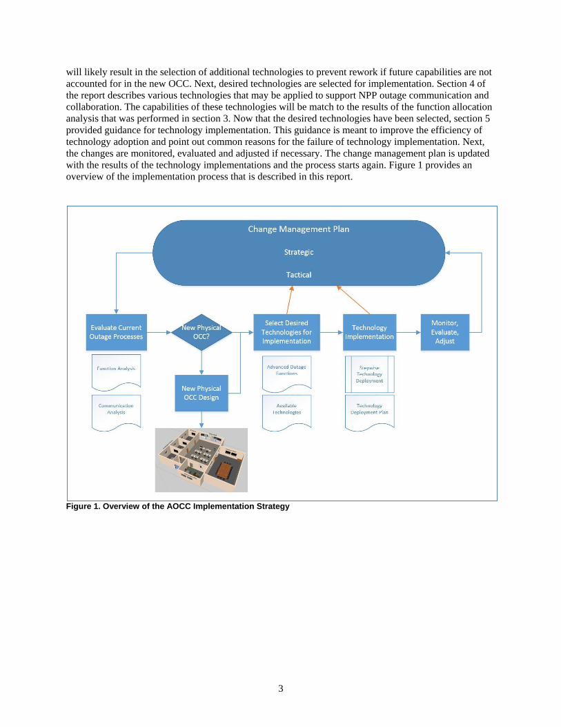
will likely result in the selection of additional technologies to prevent rework if future capabilities are not accounted for in the new OCC. Next, desired technologies are selected for implementation. Section 4 of the report describes various technologies that may be applied to support NPP outage communication and collaboration. The capabilities of these technologies will be match to the results of the function allocation analysis that was performed in section 3. Now that the desired technologies have been selected, section 5 provided guidance for technology implementation. This guidance is meant to improve the efficiency of technology adoption and point out common reasons for the failure of technology implementation. Next, the changes are monitored, evaluated and adjusted if necessary. The change management plan is updated with the results of the technology implementations and the process starts again. Figure 1 provides an overview of the implementation process that is described in this report.
Figure 1. Overview of the AOCC Implementation Strategy
4
2 ESTABLISH A CHANGE MANAGEMENT PLAN
Establishing a method to implement change that is consistent and follows a repeatable process is one of the most effective and efficient approaches to change any given process that is in need of improvement. However, failure to effectively manage change as it relates to the implementation of outage improvement may result in failed efforts, rework, extended implementation time, resistance, lack of buy-in, loss of credibility in leadership, and skepticism and cynicism in employees, most of which equate to increased cost. The purpose of an outage improvement change management plan is to guide the implementation of an AOCC and/or to deploy advanced technologies to improve outages in commercial NPPs. The basic change management processes described here has been designed to assist commercial utilities in developing a strategic plan for the overall outage process improvement effort, and multiple tactical plans for individual technologies to be deployed.
2.1 Method
This section provides a repeatable method for implementing technology and process changes at a NPP to improve outage processes and technology adoption, and has the potential to be easily utilized for other related efforts. This plan describes basic steps for implementing outage improvement initiatives using change management processes. The methodology described here considers the technical, business, and human aspects of the outage improvement process change. As with most projects, a graded approach should be used to ensure that the appropriate level of rigor is applied for change efforts at any organizational or system level, as well as changes needing more immediate versus gradual implementation. This method emphasizes the importance of following a process designed for improving outages in in commercial NPPs (Appendix F & G – Strategic and Tactical Change Management Checklists, respectively) to ensure successful implementation. There are several resources readily available should the user of this information desire a deeper understanding of the fundamentals for change management in general. A simple web search will easily produce the numerous change management resources.
2.2 Roles and Responsibilities
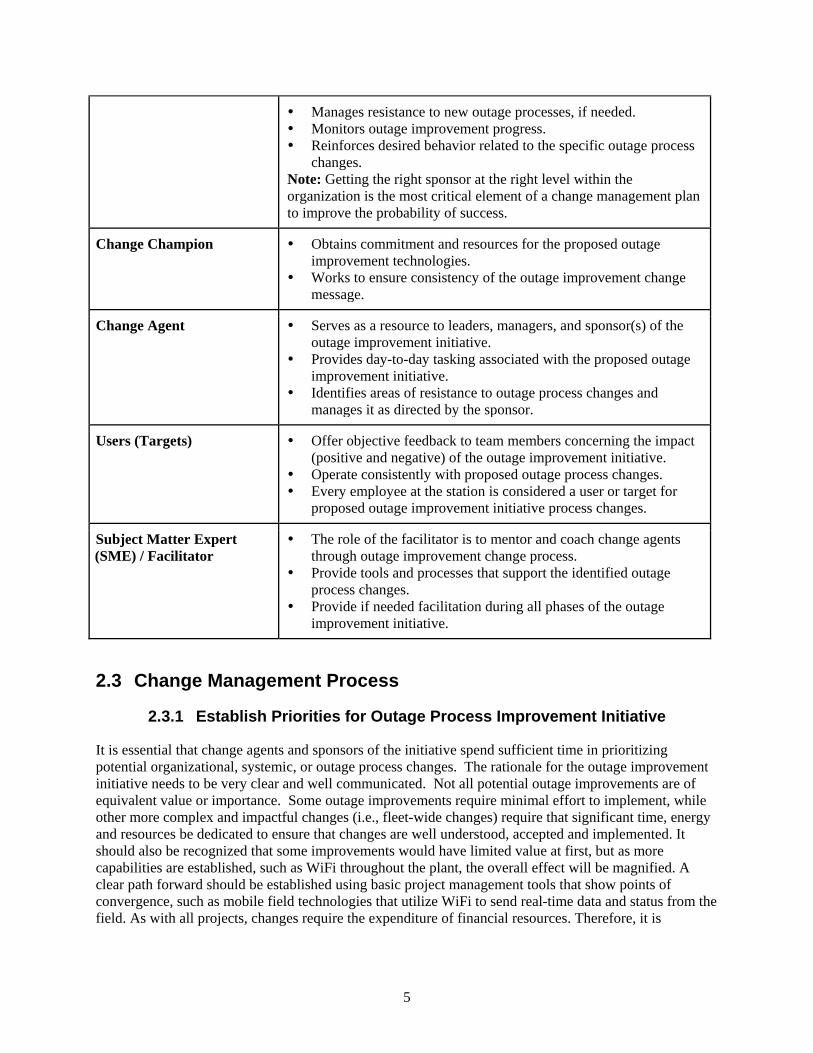
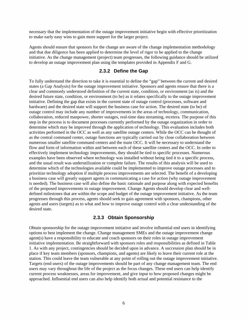
To improve the probability of success, it is essential to identify staff within the organization that will fulfill the roles identified in Table 1 below. It also important to have each of these persons recognize their particular role in the change management process; otherwise certain critical actions or decisions may be missed, making the project vulnerable to failure. As noted in Table 1, it is of primary importance that a sponsor of the outage improvement initiative be identified, as this person brings the power to authorize funds and dedicate resources that are needed for project success. Table 1. Change Management Roles and Responsibilities.
Performer Roles and Responsibilities
Change Sponsor Authorizes the desired outage improvements. Authorizes, as needed, the resources (time, dollars, human capital)
for outage improvement plan implementation. Interacts/communicates with stakeholders on the outage
improvement team.
5
Manages resistance to new outage processes, if needed. Monitors outage improvement progress. Reinforces desired behavior related to the specific outage process
changes. Note: Getting the right sponsor at the right level within the organization is the most critical element of a change management plan to improve the probability of success.
Change Champion Obtains commitment and resources for the proposed outage improvement technologies.
Works to ensure consistency of the outage improvement change message.
Change Agent Serves as a resource to leaders, managers, and sponsor(s) of the outage improvement initiative.
Provides day-to-day tasking associated with the proposed outage improvement initiative.
Identifies areas of resistance to outage process changes and manages it as directed by the sponsor.
Users (Targets) Offer objective feedback to team members concerning the impact (positive and negative) of the outage improvement initiative.
Operate consistently with proposed outage process changes. Every employee at the station is considered a user or target for
proposed outage improvement initiative process changes.
Subject Matter Expert (SME) / Facilitator
The role of the facilitator is to mentor and coach change agents through outage improvement change process.
Provide tools and processes that support the identified outage process changes.
Provide if needed facilitation during all phases of the outage improvement initiative.
2.3 Change Management Process
2.3.1 Establish Priorities for Outage Process Improvement Initiative
It is essential that change agents and sponsors of the initiative spend sufficient time in prioritizing potential organizational, systemic, or outage process changes. The rationale for the outage improvement initiative needs to be very clear and well communicated. Not all potential outage improvements are of equivalent value or importance. Some outage improvements require minimal effort to implement, while other more complex and impactful changes (i.e., fleet-wide changes) require that significant time, energy and resources be dedicated to ensure that changes are well understood, accepted and implemented. It should also be recognized that some improvements would have limited value at first, but as more capabilities are established, such as WiFi throughout the plant, the overall effect will be magnified. A clear path forward should be established using basic project management tools that show points of convergence, such as mobile field technologies that utilize WiFi to send real-time data and status from the field. As with all projects, changes require the expenditure of financial resources. Therefore, it is
6
necessary that the implementation of the outage improvement initiative begin with effective prioritization to make early easy wins to gain more support for the larger project. Agents should ensure that sponsors for the change are aware of the change implementation methodology and that due diligence has been applied to determine the level of rigor to be applied to the change initiative. As the change management (project) team progresses, the following guidance should be utilized to develop an outage improvement plan using the templates provided in Appendix F and G.
2.3.2 Define the Gap
To fully understand the direction to take it is essential to define the “gap” between the current and desired states (a Gap Analysis) for the outage improvement initiative. Sponsors and agents ensure that there is a clear and commonly understood definition of the current state, condition, or environment (as is) and the desired future state, condition, or environment (to be) as it relates specifically to the outage improvement initiative. Defining the gap that exists in the current state of outage control (processes, software and hardware) and the desired state will support the business case for action. The desired state (to be) of outage control may include any number of improvements in the areas of technology, communication, collaboration, reduced manpower, shorter outages, real-time data streaming, etcetera. The purpose of this step in the process is to document processes currently performed by the outage organization in order to determine which may be improved through the application of technology. This evaluation includes both activities performed in the OCC as well as any satellite outage centers. While the OCC can be thought of as the central command center, outage functions are typically carried out by close collaboration between numerous smaller satellite command centers and the main OCC. It will be necessary to understand the flow and form of information within and between each of these satellite centers and the OCC. In order to effectively implement technology improvements, they should be tied to specific processes. Numerous examples have been observed where technology was installed without being tied it to a specific process, and the usual result was underutilization or complete failure. The results of this analysis will be used to determine which of the technologies available could be implemented to improve outage processes and to prioritize technology adoption if multiple process improvements are selected. The benefit of a developing a business case will greatly support agents in communicating a case for action (why outage improvement is needed). The business case will also define the basic rationale and purpose along with expected benefits of the proposed improvements in outage improvement. Change Agents should develop clear and well-defined milestones that are within the scope and budget of the outage improvement initiative. As the team progresses through this process, agents should seek to gain agreement with sponsors, champions, other agents and users (targets) as to what and how to improve outage control with a clear understanding of the desired state.
2.3.3 Obtain Sponsorship
Obtain sponsorship for the outage improvement initiative and involve influential end users in identifying options to best implement the change. Change management SMEs and the outage improvement change agent(s) have a responsibility to educate and coach sponsors on their roles in outage improvement initiative implementation. Be straightforward with sponsors roles and responsibilities as defined in Table 1. As with any project, contingencies should be decided upon in advance. A succession plan should be in place if key team members (sponsors, champions, and agents) are likely to leave their current role at the station. This could leave the team vulnerable at any point of rolling out the outage improvement initiative. Targets (end users) of the outage improvements should be part of any change management team. The end users may vary throughout the life of the project as the focus changes. These end users can help identify current process weaknesses, areas for improvement, and give input to how proposed changes might be approached. Influential end users can also help identify both actual and potential resistance to the
7
proposed changes. End users should help identify mitigation strategies to help create a smooth transition to the new processes or use of new technologies.
2.3.4 Effectively Communicate the Upcoming Changes
Effective communication of upcoming changes and existence of a project will go a long way to reduce resistance by end users. As early as possible start building a communication plan (see Appendix H). Communications should include:
o Overall outage improvement goals and objectives o Proposed changes and their impact (positive and negative) o Key milestones and associated dates o Outage improvement initiative team members o Solicitation for ideas to create a sense of inclusion o A website or other locations for station staff to find additional information
The outage improvement team should monitor the impact of change and provide input to continuously seek to improve communication to station personnel. The team should have a clear and concise message (an elevator speech) prior to each tactical change to minimize confusion and misunderstandings. Note: E-mail should never be used as the primary medium for communicating a proposed change.
2.3.5 Reinforce Desired Behaviors Consistent with Metrics
To create lasting change and prevent staff from returning to old processes or technologies, managers and supervisors at the station should reinforce the desired behaviors (rewards/recognition/consequences) consistent with the project metrics. Observations conducted in NPP outage control centers by INL staff have identified key elements that should be considered when rolling out new technologies to support outage improvement, including: Physically remove old technologies, such as white boards, when new technologies (i.e., large
touch screen monitors) are deployed to prevent outage staff from returning to old methods of displaying information.
To maximize the end users’ probability of using new technologies (software or hardware), consider changing the written processes that define how the technologies will be utilized, such as the Issue Response process. It is not sufficient to simply make a new piece of communication/collaboration software available without integrating it into the process(es) that are expected to utilize it.
End user training should be provided prior to any change to outage control processes. This training should include hands-on experience in using any new tools and technologies.
Expert technical support should be provided until full adoption by all shifts. This may take a full outage cycle to accomplish and should be considered when calculating the cost to deploy.
Lessons learned should be captured iteratively (as the technology or tools are used) to capture good practices and identify areas for improvement prior to the next outage or if possible in real-time.
2.3.6 Continually Monitor Scope and Definition of Plan
The outage improvement team should continually monitor for scope creep, expansions of work scope without corresponding expansion of the budget and work plan. When potential additions to work scope arise, the team should continually make necessary adjustments to plan; however, they should always keep the end goal in mind. Scope creep can be very costly and limit the ability of the team to meet milestones.
8
Additionally, keeping sponsors and champions updated on the rationale for scope change will be essential in maintaining their support.
2.4 Documentation
The change management plan is documented using the strategic and tactical change management checklists provided in Appendices F and G. Typically one strategic checklist would govern the overall outage process improvement effort, and multiple tactical checklists would be used to govern individual technology implementations, because the change agents would likely be different for each implementation. Appendix E provides guidance for filling out the change management checklists, and the change management plan is described in more detail in Section 5.3.1.
9
3 EVALUATE CURRENT OUTAGE PROCESSES
The purpose of this step is to document processes currently (as is) performed by the outage organization in order to determine which aspects of the outage may be improved through the application of technology. This evaluation includes both activities performed in the OCC as well as any satellite outage centers. While the OCC can be thought of as the central command center, outage functions are typically carried out by close collaboration between numerous smaller satellite command centers and the main OCC. It will be necessary to understand the flow and form of information within and between each of these satellite centers and the OCC. In order to effectively implement technology improvements, they should be tied to specific processes. Numerous examples have been observed where technology was installed without being tied it to a specific process, and the usual result was underutilization or complete failure. For example, the project team has observed interactive touch boards installed in OCCs, only to find them unused since whoever installed them did not assign a specific process to the technology. The results of this analysis will be used to determine which of the available technologies could be implemented to improve outage processes and to prioritize technology adoption if multiple process improvements are selected.
3.1 Overview of OCC Functions
In evaluating outage processes for potential enhancement utilizing modern technology, it has been useful to group individual tasks or ideas for improvement by the high level OCC function they support. The following high-level functions of the OCC were derived from the initial function analysis. These high level functions should be similar for most NPP outage organizations.
1. Process Information Inflow a. Status of scheduled activities b. Reports of new emergent issues c. Status of emergent issue resolution d. Requests for assistance
2. Manage Work Schedule a. Status of ongoing work tracking b. Revisions to schedule due to delays c. Coordination of required support
3. Manage Emergent Issues a. Create and manage recovery plan b. Manage schedule impacts
4. Manage Plant Conditions a. Technical specification and mode change requirements b. Defense in depth, protected systems and plant risk monitoring
5. Process Information Outflow a. Overall outage schedule status b. Resource requests/notifications c. Communicate schedule changes to affected parties d. Requests for status
10
3.2 Overview of Function Analysis (FA) in Support of Technology Deployment at NPPs
Functional Requirements Analysis (FRA) is a phased systems engineering method that aims to define a system's functional architecture in terms of the operations that must be performed in order to meet the mission goals of the system. In the high-level analysis, such as the one shown in Section 3.1, system functions are partitioned into requirements for sub-system functions. In a low-level functional analysis, the aim is to decompose the high-level functions into a coherent set of executable functions associated with operational conditions or modes, specific systems, and major components. The goal of the functional analysis at this level is to determine the functions that are associated with high-level operational goals and create a framework for an understanding of the relative role of human or system controllers. Because introducing technology almost always changes performance requirements for NPP staff, it is necessary to characterize and understand the impact on performance requirements in advance, during planning stages. As part of the process, the FRA naturally guides functional allocation between NPP personnel as well as between NPP personnel and the new technology. FA and FRA are related to work domain analysis (WDA) and establishing a work domain model of goal-oriented work performed during the outage that can be used to help identify technology needs. When performing the WDA, it is useful to take into consideration the perspective of multiple stakeholders, including engineering, management, operations, rad con, maintenance, and I&C. As the WDA is performed, it becomes clear that there is a human component involved in technology change-out and increased levels of automation. For example, planners care about feasibility, human factors personnel are concerned about visibility, operability, and feedback, and management is concerned about cost, including schedule and resource requirements. Additionally, the FA will need take into account the functions described in Section 3.1 of this report. Prior to introducing AOCC candidate technologies, the existing patterns for detecting, managing, and correcting problems associated with paper-based systems and face-to-face outage communication should be documented, measured in terms of queue times and miscommunications, and overall reliability and cost assessed. Next, trade-off regarding digital implementation and improved reliability should be assessed. For example, archival capability based on retrieving paper-based documentation or PDFs of paper-based documents should be compared to gains expected through introduction of digital technology. However, more granular analysis is required to answer such questions as, “Should the final system be self-organizing?” and “How should the organizational leads for outage control execute database queries?” To some extent, there will be overlaps between organizations and their data needs. The same data may end up being used in different ways, and the manner in which data are to be used will become apparent through the administration and execution of the functional requirements analysis.
3.2.1 Requirements Gathering in Support of FA
Requirements determination for human-system performance during outages is well served through consideration of various operating scenarios and contexts. By so doing it is possible to anticipate the range of activities, tolerances, and expectancies related to human performance during outage tasks. It is possible, in turn, to examine the cognitive demand on the operator and specify the allocation of tasks between the human and automation. For example, higher-level tasks are decomposed to determine the
11
actions that are required to accomplish the tasks. By understanding system needs and user performance requirements, it is also possible to gather data that can assist the designer regarding the indications and triggers for human performance. For example, shift turnover often involves passing the status of maintenance actions from one shift to the next; this status is often a trigger for the next shift regarding recognizing the extent and order of work to be accomplished. To the extent feasible, activity sampling of current outage work processes can be performed to highlight those areas where aspects of tasks are improved by implementation of advanced technologies. Another aspect of function allocation involves identification of tasks that are: 1) allocated to NPP staff, 2) allocated to the system, such as automatic time stamping and collation, and 3) require an interaction between the operator and the system.
3.2.2 Model for Allocating AOCC Functions
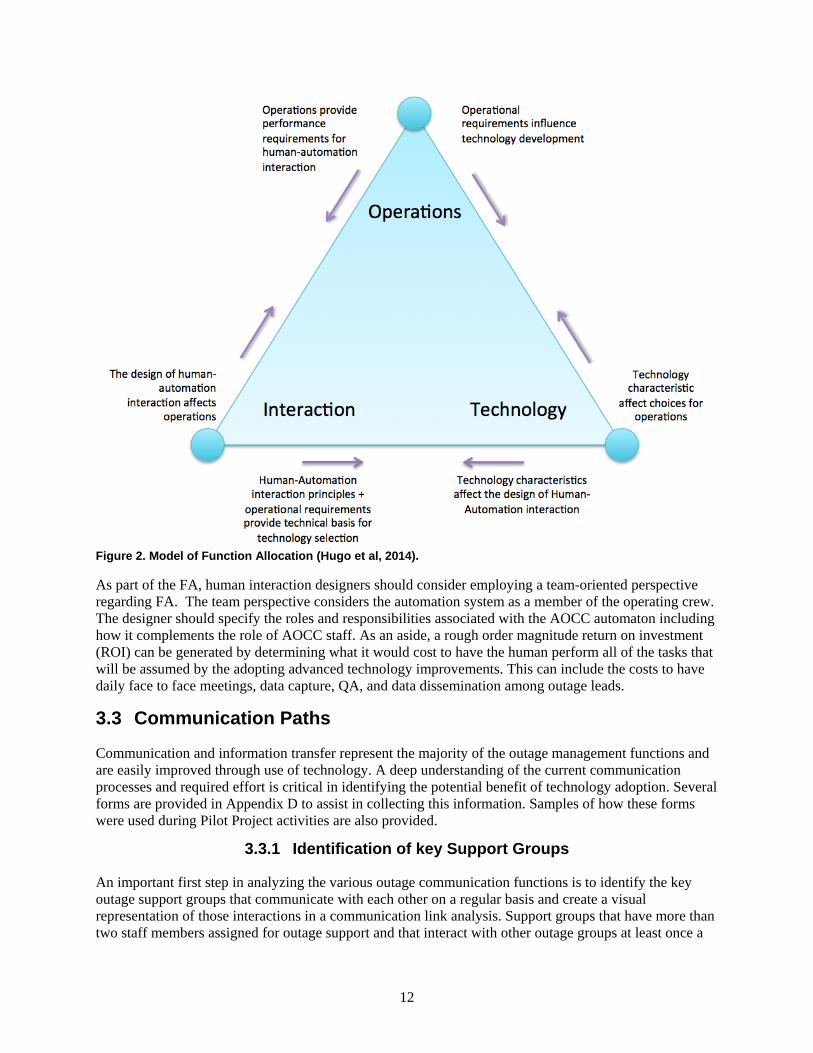
Hugo, Gertman, and Joe (2014) provide an overall conceptualization for technology and allocation integration, shown in Figure 2. It is applicable to balancing and allocating technology, system operations, and human system interaction for NPP operations including the use of technology in support of AOCC mission planning and execution. This model provides a number of insights. For example, the technology characteristics influence both the selection of the technology as well as the design of the intended interaction with the technology. The human-system performance requirements determine the design of the interaction as well; thus, the final interaction design must take into account performance requirements, human limitations and capabilities, and the technology characteristics. For example, some technology may be powerful but require a heavy allocation of effort for the staff to use, whereas other technology is more limited in capabilities but easier to use. Designers will want to look at the cognitive demands associated with the operation of one technology versus another. Depending on factors such as overlapping or concurrent tasks, the designer may wish to select technologies that are easier to operate, require less training, or are less prone to error. For example, a classic human factors design principle is to not require staff to integrate information from two sources, but to let the technology do this for personnel.
12
Figure 2. Model of Function Allocation (Hugo et al, 2014).
As part of the FA, human interaction designers should consider employing a team-oriented perspective regarding FA. The team perspective considers the automation system as a member of the operating crew. The designer should specify the roles and responsibilities associated with the AOCC automaton including how it complements the role of AOCC staff. As an aside, a rough order magnitude return on investment (ROI) can be generated by determining what it would cost to have the human perform all of the tasks that will be assumed by the adopting advanced technology improvements. This can include the costs to have daily face to face meetings, data capture, QA, and data dissemination among outage leads.
3.3 Communication Paths
Communication and information transfer represent the majority of the outage management functions and are easily improved through use of technology. A deep understanding of the current communication processes and required effort is critical in identifying the potential benefit of technology adoption. Several forms are provided in Appendix D to assist in collecting this information. Samples of how these forms were used during Pilot Project activities are also provided.
3.3.1 Identification of key Support Groups
An important first step in analyzing the various outage communication functions is to identify the key outage support groups that communicate with each other on a regular basis and create a visual representation of those interactions in a communication link analysis. Support groups that have more than two staff members assigned for outage support and that interact with other outage groups at least once a
13
shift should be included in this analysis. Key support groups typically include: maintenance, individual maintenance shops, engineering, operations, schedulers, an issues response team (IRT), the main control room (MCR), or the Work Execution Center (WEC).
3.3.2 Map of Communications Between Support Groups and OCC
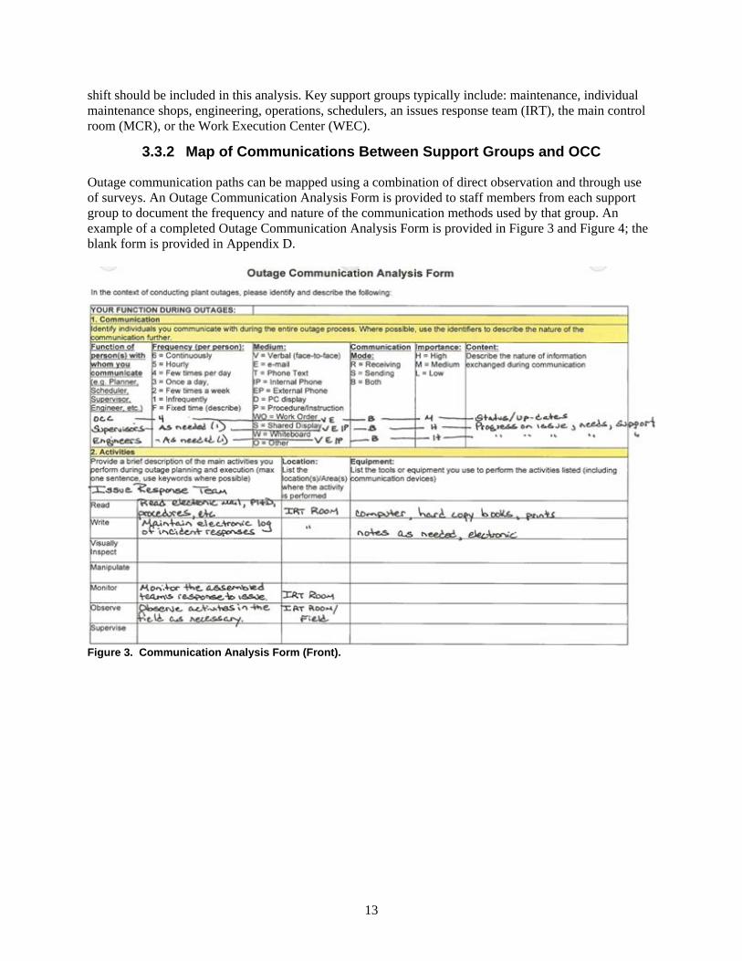
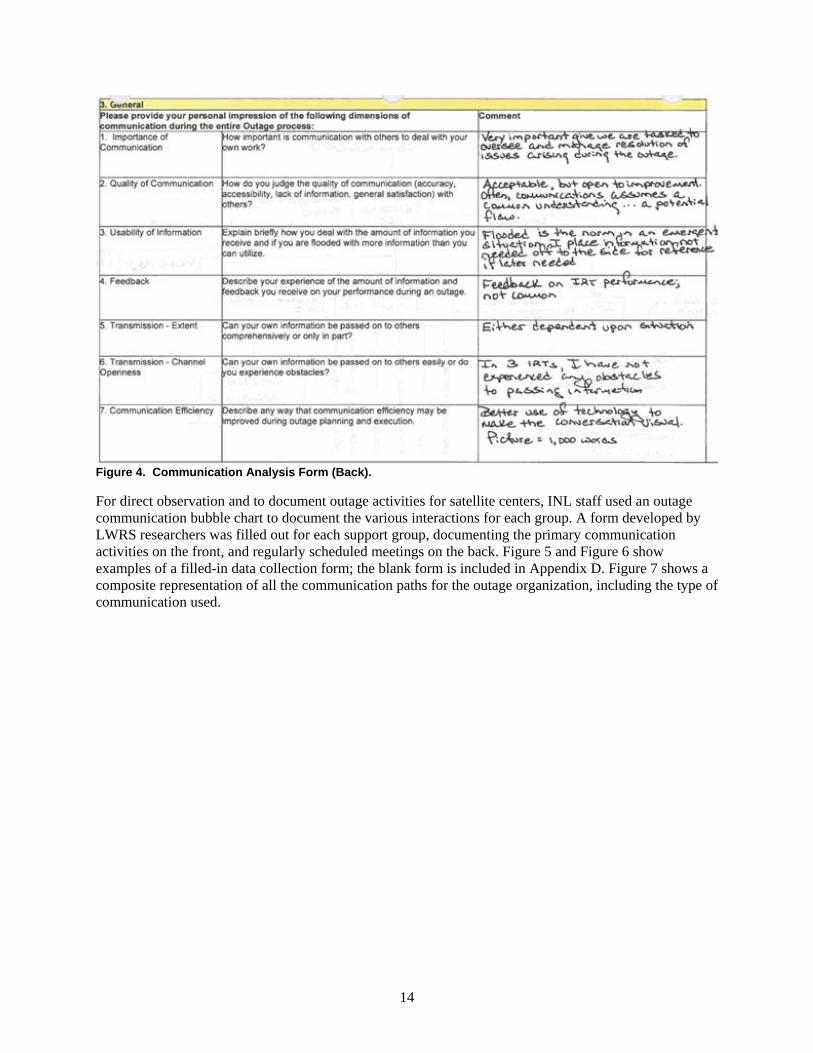
Outage communication paths can be mapped using a combination of direct observation and through use of surveys. An Outage Communication Analysis Form is provided to staff members from each support group to document the frequency and nature of the communication methods used by that group. An example of a completed Outage Communication Analysis Form is provided in Figure 3 and Figure 4; the blank form is provided in Appendix D.
Figure 3. Communication Analysis Form (Front).
14
Figure 4. Communication Analysis Form (Back).
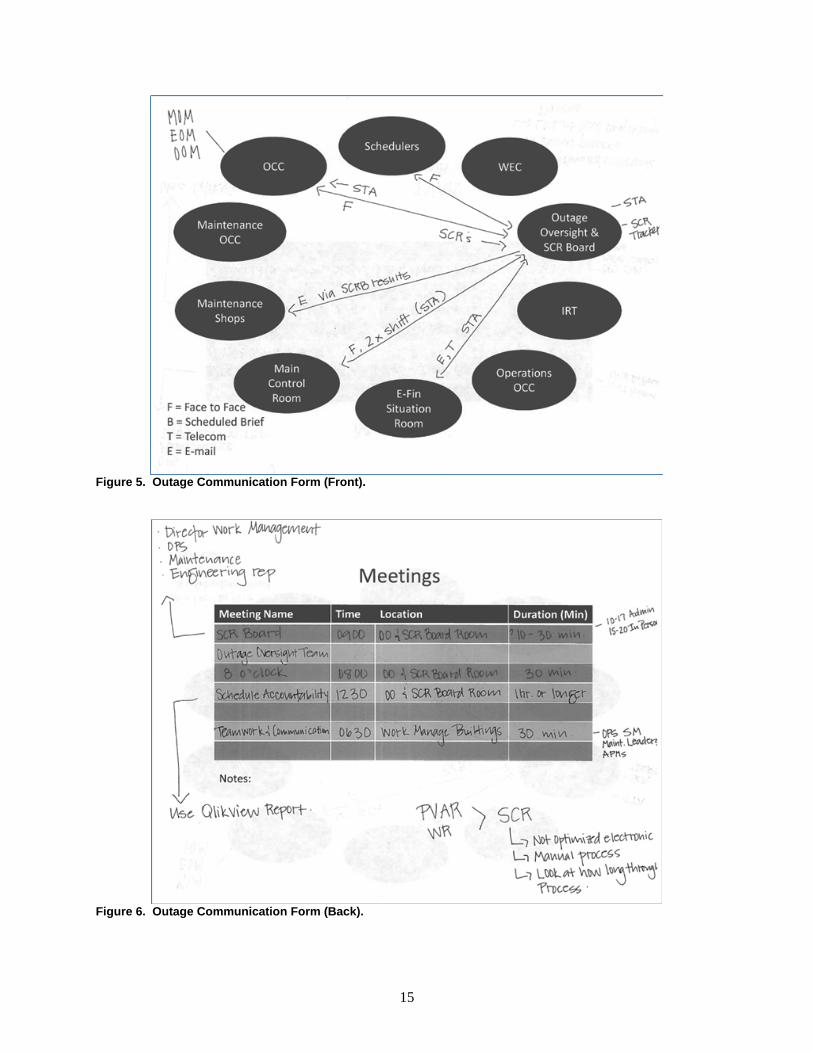
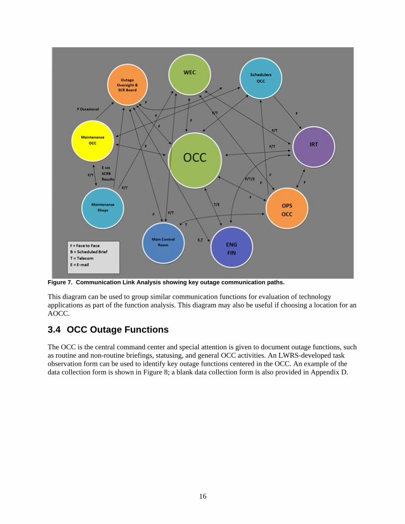
For direct observation and to document outage activities for satellite centers, INL staff used an outage communication bubble chart to document the various interactions for each group. A form developed by LWRS researchers was filled out for each support group, documenting the primary communication activities on the front, and regularly scheduled meetings on the back. Figure 5 and Figure 6 show examples of a filled-in data collection form; the blank form is included in Appendix D. Figure 7 shows a composite representation of all the communication paths for the outage organization, including the type of communication used.
15
Figure 5. Outage Communication Form (Front).
Figure 6. Outage Communication Form (Back).
16
Figure 7. Communication Link Analysis showing key outage communication paths.
This diagram can be used to group similar communication functions for evaluation of technology applications as part of the function analysis. This diagram may also be useful if choosing a location for an AOCC.
3.4 OCC Outage Functions
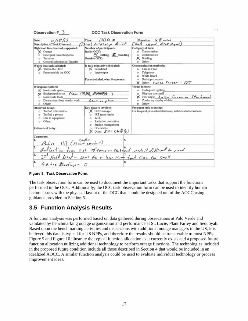
The OCC is the central command center and special attention is given to document outage functions, such as routine and non-routine briefings, statusing, and general OCC activities. An LWRS-developed task observation form can be used to identify key outage functions centered in the OCC. An example of the data collection form is shown in Figure 8; a blank data collection form is also provided in Appendix D.
17
Figure 8. Task Observation Form.
The task observation form can be used to document the important tasks that support the functions performed in the OCC. Additionally; the OCC task observation form can be used to identify human factors issues with the physical layout of the OCC that should be designed out of the AOCC using guidance provided in Section 6.
3.5 Function Analysis Results
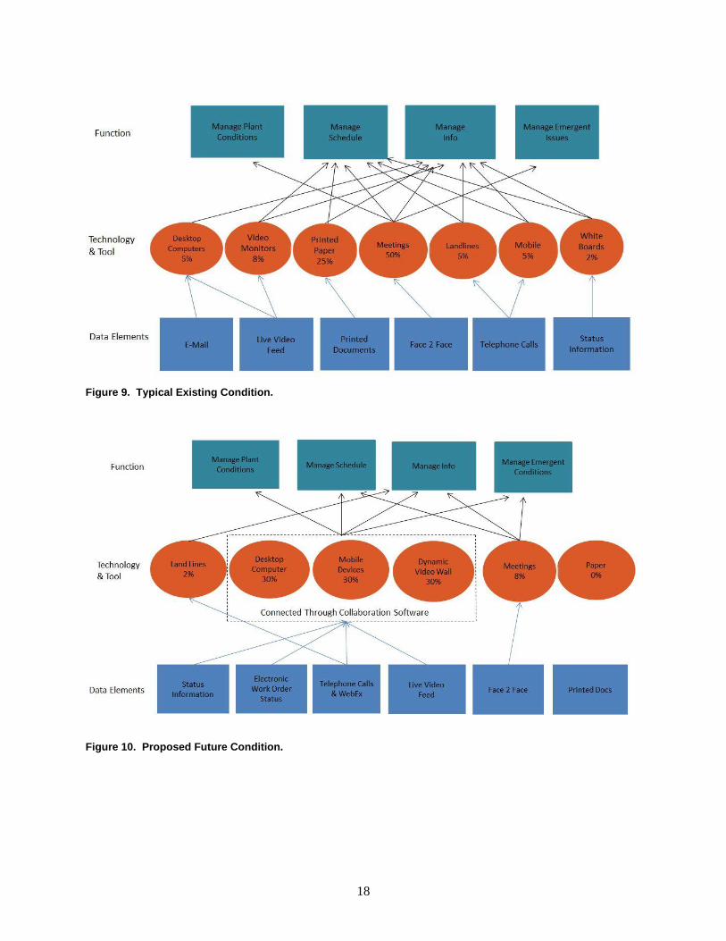
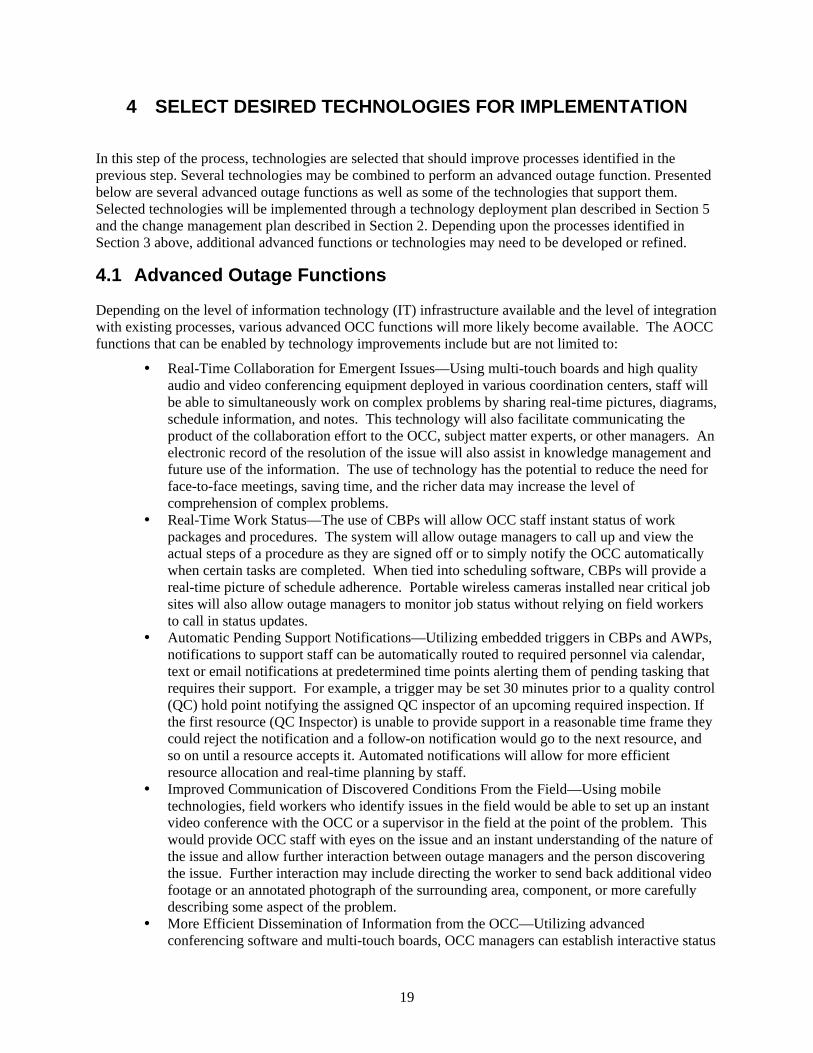
A function analysis was performed based on data gathered during observations at Palo Verde and validated by benchmarking outage organization and performance at St. Lucie, Plant Farley and Sequoyah. Based upon the benchmarking activities and discussions with additional outage managers in the US, it is believed this data is typical for US NPPs, and therefore the results should be transferable to most NPPs. Figure 9 and Figure 10 illustrate the typical function allocation as it currently exists and a proposed future function allocation utilizing additional technology to perform outage functions. The technologies included in the proposed future condition include all those described in Section 4 that would be included in an idealized AOCC. A similar function analysis could be used to evaluate individual technology or process improvement ideas.
18
Figure 9. Typical Existing Condition.
Figure 10. Proposed Future Condition.
19
4 SELECT DESIRED TECHNOLOGIES FOR IMPLEMENTATION
In this step of the process, technologies are selected that should improve processes identified in the previous step. Several technologies may be combined to perform an advanced outage function. Presented below are several advanced outage functions as well as some of the technologies that support them. Selected technologies will be implemented through a technology deployment plan described in Section 5 and the change management plan described in Section 2. Depending upon the processes identified in Section 3 above, additional advanced functions or technologies may need to be developed or refined.
4.1 Advanced Outage Functions
Depending on the level of information technology (IT) infrastructure available and the level of integration with existing processes, various advanced OCC functions will more likely become available. The AOCC functions that can be enabled by technology improvements include but are not limited to:
Real-Time Collaboration for Emergent Issues—Using multi-touch boards and high quality audio and video conferencing equipment deployed in various coordination centers, staff will be able to simultaneously work on complex problems by sharing real-time pictures, diagrams, schedule information, and notes. This technology will also facilitate communicating the product of the collaboration effort to the OCC, subject matter experts, or other managers. An electronic record of the resolution of the issue will also assist in knowledge management and future use of the information. The use of technology has the potential to reduce the need for face-to-face meetings, saving time, and the richer data may increase the level of comprehension of complex problems.
Real-Time Work Status—The use of CBPs will allow OCC staff instant status of work packages and procedures. The system will allow outage managers to call up and view the actual steps of a procedure as they are signed off or to simply notify the OCC automatically when certain tasks are completed. When tied into scheduling software, CBPs will provide a real-time picture of schedule adherence. Portable wireless cameras installed near critical job sites will also allow outage managers to monitor job status without relying on field workers to call in status updates.
Automatic Pending Support Notifications—Utilizing embedded triggers in CBPs and AWPs, notifications to support staff can be automatically routed to required personnel via calendar, text or email notifications at predetermined time points alerting them of pending tasking that requires their support. For example, a trigger may be set 30 minutes prior to a quality control (QC) hold point notifying the assigned QC inspector of an upcoming required inspection. If the first resource (QC Inspector) is unable to provide support in a reasonable time frame they could reject the notification and a follow-on notification would go to the next resource, and so on until a resource accepts it. Automated notifications will allow for more efficient resource allocation and real-time planning by staff.
Improved Communication of Discovered Conditions From the Field—Using mobile technologies, field workers who identify issues in the field would be able to set up an instant video conference with the OCC or a supervisor in the field at the point of the problem. This would provide OCC staff with eyes on the issue and an instant understanding of the nature of the issue and allow further interaction between outage managers and the person discovering the issue. Further interaction may include directing the worker to send back additional video footage or an annotated photograph of the surrounding area, component, or more carefully describing some aspect of the problem.
More Efficient Dissemination of Information from the OCC—Utilizing advanced conferencing software and multi-touch boards, OCC managers can establish interactive status
20
briefings in which stakeholders may participate from any location, on site or off, using a variety of devices, including desktop computers, laptops, smart phones, and tablet computers.
Real-Time Requirements Monitor—Utilizing a combination of information pulled from the status of procedures, real-time plant status from the plant computer and plant logs, the OCC managers will be able to more easily display status and readiness for key activities or tasks.
Mobile Alerts—Utilizing a messaging system similar to instant messaging used by most smart phones, NPP personnel could be updated by the OCC managers when important milestones are met or plant conditions change. For example, the system could provide alerts for such events as window closures, plant risk level changes, protected system changes, industrial or radiological hazards, etcetera. These messages would consist of a simple statement of the condition, but also provide more detailed information for those that require it through use of an information icon. These alerts could be also sent to handheld devices, desktop computers, and large screen displays throughout the plant.
4.2 Available Technologies
Several technologies have shown promise at NPPs for improving the collective situational awareness of the organization. Typically these technologies are combined to support the advanced outage functions described above, but they may be implemented individually or as part of some non-outage process improvement. Many of these technologies have been evaluated at INL or are currently being evaluated at pilot project utilities; some specific examples of these technologies are presented for information only and should not be considered as an endorsement, as there are usually several other equally capable options. Where possible, additional options are presented, although some have not have been evaluated for this application. Information is provided from the manufacturers’ literature to help describe the capabilities of the described hardware and software.
4.2.1 Touch Enabled Interactive Displays
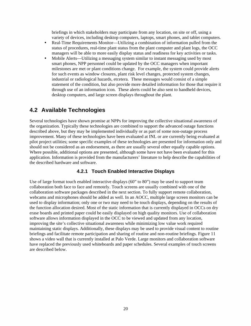
Use of large format touch enabled interactive displays (60” to 80”) may be used to support team collaboration both face to face and remotely. Touch screens are usually combined with one of the collaboration software packages described in the next section. To fully support remote collaboration, webcams and microphones should be added as well. In an AOCC, multiple large screen monitors can be used to display information; only one or two may need to be touch displays, depending on the results of the function allocation desired. Most of the static information that is currently displayed in OCCs on dry erase boards and printed paper could be easily displayed on high quality monitors. Use of collaboration software allows information displayed in the OCC to be viewed and updated from any location, improving the site’s collective situational awareness while minimizing low value work required maintaining static displays. Additionally, these displays may be used to provide visual content to routine briefings and facilitate remote participation and sharing of routine and non-routine briefings. Figure 11 shows a video wall that is currently installed at Palo Verde. Large monitors and collaboration software have replaced the previously used whiteboards and paper schedules. Several examples of touch screens are described below.
21
Figure 11. Video wall installed at Palo Verde.
4.2.1.1 SMART Boards
The SMART BOARD is an interactive flat panel whiteboard designed for real-time collaboration. Files, applications, websites and multimedia may be displayed and manipulated via both touch screen capability and a pen-type stylus for capturing handwritten information, which may be converted to text. Lists of all types—inventory, ordering, maintenance, etcetera, may be uploaded and shared site wide via PCs and mobile devices, such as tablets and smartphones. The SMART Board has been used in the outage communication and collaboration research carried out by the INL team at the HSSL.
4.2.1.2 Sharp Aquos Boards
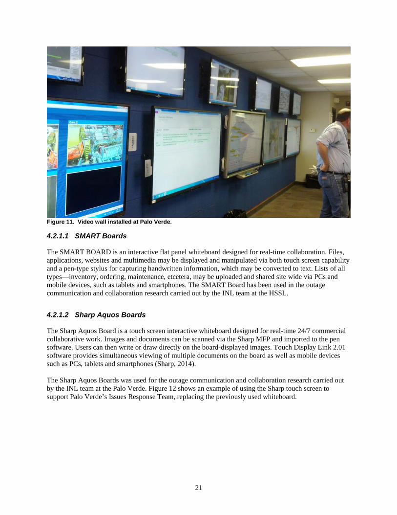
The Sharp Aquos Board is a touch screen interactive whiteboard designed for real-time 24/7 commercial collaborative work. Images and documents can be scanned via the Sharp MFP and imported to the pen software. Users can then write or draw directly on the board-displayed images. Touch Display Link 2.01 software provides simultaneous viewing of multiple documents on the board as well as mobile devices such as PCs, tablets and smartphones (Sharp, 2014). The Sharp Aquos Boards was used for the outage communication and collaboration research carried out by the INL team at the Palo Verde. Figure 12 shows an example of using the Sharp touch screen to support Palo Verde’s Issues Response Team, replacing the previously used whiteboard.
22
Before After
Figure 12. Use of a touch enabled interactive display to support emergent issues response.
4.2.2 Collaboration Software
Collaboration software, also known as groupware, can be an effective tool for outage communication. Collaboration software is one element of a larger topic of Computer Supported Cooperative Work (CSCW). CSCW combines the understanding of the way people work in groups with enabling technologies of computer networking, associated hardware, software, services, and techniques. First introduced in 1984, CSCW provides two approaches—technology-centric or work-centric—to support groups of individuals collaborating from different locations. The technology-centric approach emphasizes the design and implementation of computer technology aimed at supporting groups working together, while the work-centric approach is geared at the design and implementation of computer systems supporting group collaboration. Further, the CSCW concept is comprised of ten dimensions (Techopedia, 2014): Time Space Interaction style Group size Infrastructure Context Privacy Collaborator mobility Extensibility Participant selection
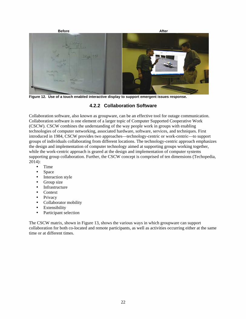
The CSCW matrix, shown in Figure 13, shows the various ways in which groupware can support collaboration for both co-located and remote participants, as well as activities occurring either at the same time or at different times.
23
Figure 13. CSCW Matrix (Johansen, 1988).
Several collaboration software package options are available to support the AOCC function described in Section 4.1. Some collaboration software supports real-time collaboration, while others support near real-time collaboration. Typically, real-time collaboration requires more expensive software, and near real time is probably adequate for most applications. A combination of near real-time software for bulk work and specialized real-time capable software for intensive collaborations may be optimal. Numerous collaboration software options exist; several collaboration software examples are described below.
4.2.2.1 SMART Meeting Pro
SMART Meeting Pro provides an unbound workspace where users may introduce text, images, hyperlinks, text notes, and other content into the “virtually unlimited collaboration workspace.” Users may pan in any direction, and either zoom in to work in detail or pan out for overview. Meeting Pro facilitates multi-display, capability-sharing collaboration workspace with real-time annotation across up to 16 displays. The Enhanced Interaction Performance ensures that interaction with content is both smooth and natural, and the software supports large files. SMART Ink 1.5 automatically enables the user to write in any application window. Meeting Pro provides increased communication flexibility, and, when used with distance collaboration software like Bridgit, Lync or WebEx, establishes a forum for remote participants to contribute their notes and ideas. Finally, in conjunction with Microsoft® Exchange®, SMART Meeting Pro™ reads meeting invitations to automatically start the meeting when you log in, loads agendas, attendee lists, links included in the meeting invite as well as any attached documents. Using the Embedded Links Feature enables SharePoint® documents to be shared in the meeting (SMART, 2014). SMART Meeting Pro has been used in the outage communication and collaboration research carried out by the INL team at the HSSL.
24
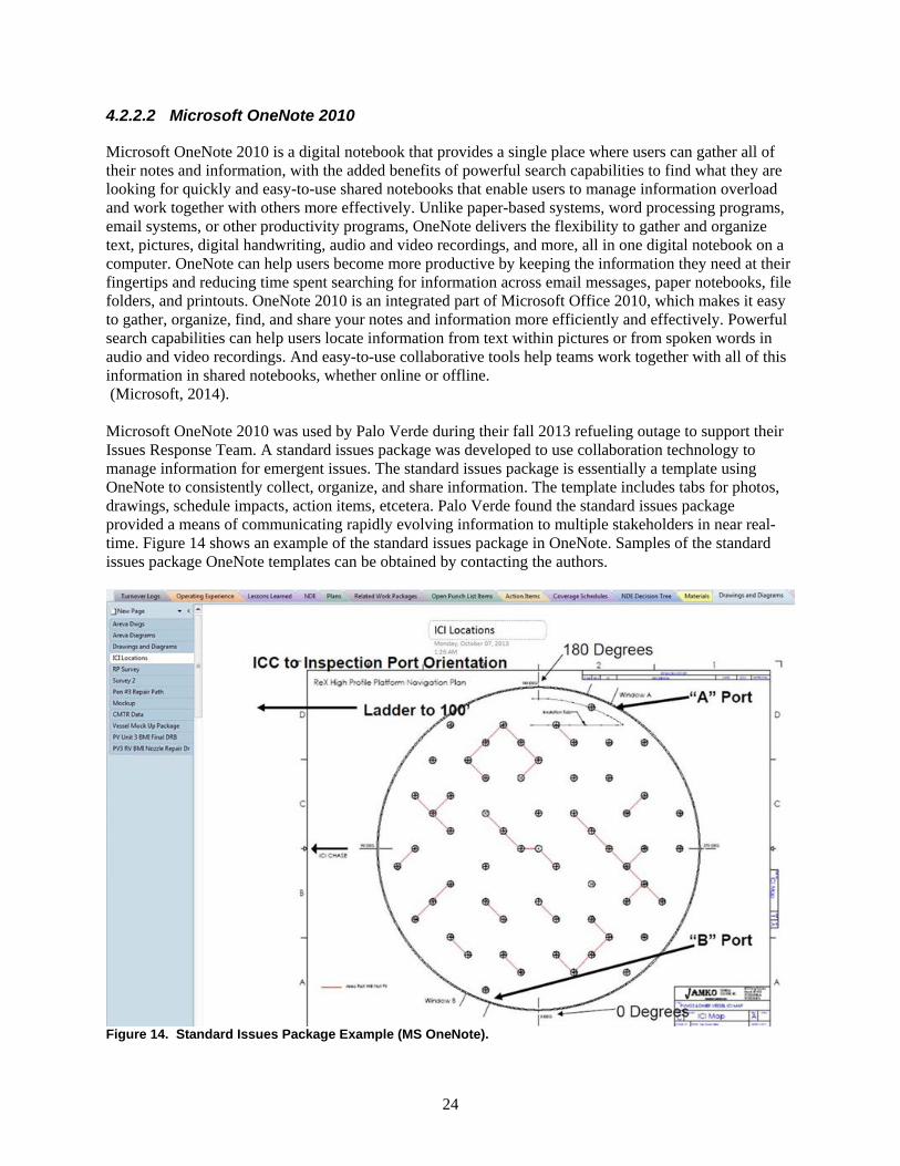
4.2.2.2 Microsoft OneNote 2010
Microsoft OneNote 2010 is a digital notebook that provides a single place where users can gather all of their notes and information, with the added benefits of powerful search capabilities to find what they are looking for quickly and easy-to-use shared notebooks that enable users to manage information overload and work together with others more effectively. Unlike paper-based systems, word processing programs, email systems, or other productivity programs, OneNote delivers the flexibility to gather and organize text, pictures, digital handwriting, audio and video recordings, and more, all in one digital notebook on a computer. OneNote can help users become more productive by keeping the information they need at their fingertips and reducing time spent searching for information across email messages, paper notebooks, file folders, and printouts. OneNote 2010 is an integrated part of Microsoft Office 2010, which makes it easy to gather, organize, find, and share your notes and information more efficiently and effectively. Powerful search capabilities can help users locate information from text within pictures or from spoken words in audio and video recordings. And easy-to-use collaborative tools help teams work together with all of this information in shared notebooks, whether online or offline. (Microsoft, 2014). Microsoft OneNote 2010 was used by Palo Verde during their fall 2013 refueling outage to support their Issues Response Team. A standard issues package was developed to use collaboration technology to manage information for emergent issues. The standard issues package is essentially a template using OneNote to consistently collect, organize, and share information. The template includes tabs for photos, drawings, schedule impacts, action items, etcetera. Palo Verde found the standard issues package provided a means of communicating rapidly evolving information to multiple stakeholders in near real-time. Figure 14 shows an example of the standard issues package in OneNote. Samples of the standard issues package OneNote templates can be obtained by contacting the authors.
Figure 14. Standard Issues Package Example (MS OneNote).
25
4.2.2.3 Google Drive
Google Drive provides storage for photos, images, drawings, and video, and facilitates simultaneous collaboration on documents. Google Drive can be installed on PCs, Macs, iPhones, iPads, or Android devices. With Google Drive downloaded on a Mac/PC, files stored on the desktop automatically sync with files stored on the web. Anything shared, moved, modified or placed in the trash will be reflected in the Google Drive when the user’s computer syncs. (Google, 2014) The authors used Google Drive to collaborate in writing this report. It allowed multiple authors to contribute simultaneously, helped coordinate effort, and simplified version control challenges.
4.2.2.4 Microsoft SharePoint
Microsoft SharePoint software, along with Office Online, provides the tools to successfully communicate and collaborate from anywhere with mobile capabilities designed to facilitate file storage, synchronization, and sharing in real-time. SharePoint provides access to work group social feeds and maintains the latest updates on collaborative content, along with tools to connect with experts in the field and answer questions. Users may browse and search for apps in the SharePoint store to increase functionality of the software or expand their collaborative efforts by using SharePoint with Yammer, an enterprise social network. SharePoint provides powerful controls that allow IT departments to manage cost, risk and time, along with added features for enhanced security.
4.2.2.5 WebEx
The WebEx software facilitates collaboration with “anyone, anywhere, anytime” (WebEx, 2014), providing the opportunity for meeting online to share information via the WebEx mobile apps for iPhone, iPad, Android or Blackberry. Users may employ the software to present dynamic online events, webinars, training, and eLearning experiences. WebEx products are delivered through the Cisco WebEx Cloud with enhanced security features. WebEx was used to collaborate between INL and Palo Verde staff working on this pilot project while planning outage pilot demonstrations.
4.2.3 Mobile Worker Devices
Mobile worker devices include any number of handheld electronic devices that provide information to and allow interaction with field workers. In the AOCC concept, mobile worker devices will support CBPs and automated work packages (AWPs) described in section 4.2.5 below, as well as providing voice and video communication capability. A number of device features are available; depending upon the specific end users’ need, typically a mid-sized tablet computer with an embedded camera and WiFi capability is sufficient. The embedded camera may be used to scan barcodes for component verification as well as support rich data transfer from the field to the OCC. Various rugged devices are an option, or rugged cases may be used to protect consumer models.
4.2.4 Remote Cameras
High quality video images are a very effective form of communication. Real-time video feeds of an issue or ongoing work can convey much more information than a static picture or voice report. Remote video cameras are currently used in several areas during NPP outages. Currently, these cameras are used to monitor outage progress in containment, on the refuel floor, and in the turbine building. These cameras
26
are typically power-over-ethernet (POE) cameras that are set up at the beginning of the outage and remain in place for the duration of the outage. If WiFi is available, WiFi enabled cameras could be used to provide temporary activity monitoring in locations not observable by the POE cameras typically installed. Additionally, battery packs could be used to provide completely wireless video monitoring capability. Another option is to use helmet mounted video cameras to stream a video signal to the OCC or other satellite center to obtain rich information about an issue or job.
4.2.5 Computer based Procedures/Automated Work Packages
CBP projects are starting to emerge in US NPPs. When CBPs and AWPs are implemented, and when WiFi connectivity is available, several of the more powerful advanced outage functions described in section 4.1 become possible. AWPs, combined with mobile worker devices and plant-wide WiFi, will allow real-time work status to be passively collected and displayed in an AOCC. Flags built into the AWPs and CBPs may be used to notify support staff of pending requirements via mobile worker devices.
4.2.6 Alternative Voice Communication
Voice communication during NPP outages currently relies heavily on fixed landline telephones and two-way radios. Two-way radios provide needed mobile communication, but are limited in the number of supported channels and are quickly overwhelmed by the number of users during an outage. Given the large numbers of diverse groups requiring intensive mobile voice communication capability, an alternative to two-way radios is needed. Alternative voice communication options include: Voice-over-internet Protocol (VoIP) radios, and cellular devices. Integrated communication packages can take advantage of multiple communication methods and bridge between them. Alternative voice communication options will be a topic of research in the near future for this project.
4.2.7 Plant Wide Wireless Networks
Many of the advanced outage functions described in section 4.1 require connectivity via WiFi. Plant wide WiFi will enable connection of mobile workers to the OCC, allow real-time status updates from CBPs and EWPs, allow the use of streaming wireless video feeds, and support VoIP communication options. Plant wide WiFi has numerous applications outside of outage management, and plants are not likely to install plant wide WiFi just for outage management; however, some NPPs install temporary WiFi in containment and other strategic locations during refueling outages. Several NPPs in the US have installed, or have current projects to install plant wide WiFi capability. For technical information regarding WiFi installation in a NPP, refer to EPRI’s Implementation Guideline for Wireless Networks and Wireless Equipment Condition Monitoring.
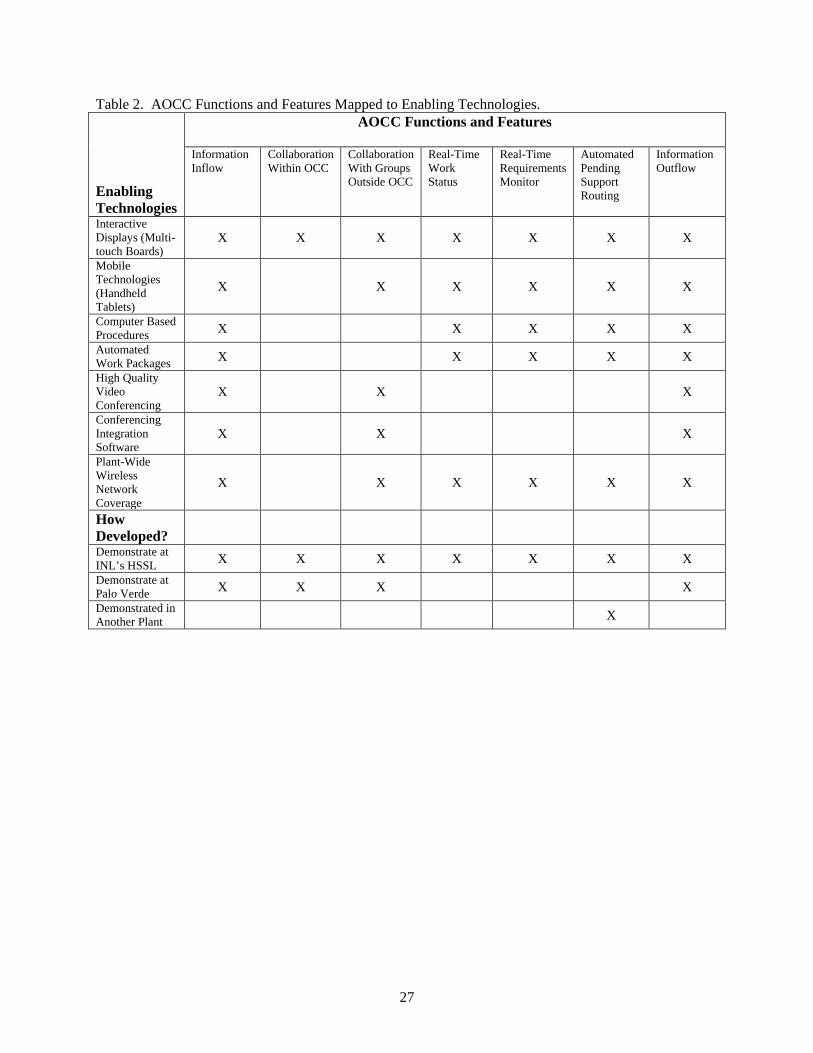
4.3 Functions vs. Available Technologies
In selecting individual technologies or advanced outage functions for implementation, it will be important to identify and catalog all the required IT infrastructure that will be required to support the proposed changes. Table 2 links these advanced OCC functions with the required enabling technologies. Some functions may be partially available without the enabling technology, but the full capability may not be realized until the IT infrastructure is improved. Since other factors will likely also be driving IT infrastructure upgrades, those existing plans should be considered when developing a Technology Deployment Plan.
27
Table 2. AOCC Functions and Features Mapped to Enabling Technologies.
Enabling Technologies
AOCC Functions and Features
Information Inflow
Collaboration Within OCC
Collaboration With Groups Outside OCC
Real-Time Work Status
Real-Time Requirements Monitor
Automated Pending Support Routing
Information Outflow
Interactive Displays (Multi-touch Boards)
X X X X X X X
Mobile Technologies (Handheld Tablets)
X X X X X X
Computer Based Procedures X X X X X Automated Work Packages X X X X X High Quality Video Conferencing
X X X
Conferencing Integration Software
X X X
Plant-Wide Wireless Network Coverage
X X X X X X
How Developed?
Demonstrate at INL’s HSSL X X X X X X X Demonstrate at Palo Verde X X X X Demonstrated in Another Plant X
28
5 TECHNOLOGY IMPLEMENTATION
Once desired technologies are selected from Section 4 to improve processes identified in step 3, a plan should be developed to help ensure successful technology deployment. If a new physical OCC will be constructed, all of the advanced outage functions should be considered, even if they are not immediately implemented in the new OCC, to prevent future rework.
5.1 Stepwise Technology Deployment
Given the current level of technology adoption used by NPPs for outage management, a stepwise introduction of technology may be prudent. The implementation of too many process and technology changes concurrently may become overwhelming for some NPP staff. The change management team should consider a stepwise process improvement and technology deployment when developing the technology deployment plan in step 5.2. Stepwise technology deployment allows staff to become proficient with each new tool individually before the next new capability is introduced. The pace at which technology deployment occurs will depend upon the current level of expertise of the staff and will vary from plant to plant. Another consideration for stepwise technology deployment involves controlling the number of initial users of new capabilities. Attempting to support a significant technology deployment that will impact the entire organization at once may overwhelm the available technical support staff and may result in poor initial impressions by the end users. Technology deployment may initially be targeted for a single group or department, the resulting lessons learned and experience will increase the probability of success when deployed organization wide. For some technology implementations it may not be practical or necessary to deploy in stages, the change management team should determine the best course of action while developing the technology deployment plan to improve the probability of success.
5.2 Development of the Technology Deployment Plan
5.2.1 Risk vs. Benefit
Evaluating risk versus benefit in any project is an important aspect of good project management. If a NPP wants to improve outage control with technology, it should determine the risks associated with all aspects of technology deployment. This should also include the risk of failure. There are two elements of risk that should be considered by the change management team: risk identification and risk mitigation. The team should also be continually on the lookout for new risks that were not originally identified or have arisen because of scope creep. The project benefits should also be identified early to weigh the pros (benefits) and cons (risks) of each new capability that can be realized by technology deployment that supports improved outage management. The change management team should utilize SMEs and other team members with an in-depth knowledge of outage control and/or the technology to be deployed to help identify as many potential risks as possible. This should be based on their experience in deploying technology, process improvement initiatives, and change management principles. Defining the potential risks will help the team recognize the potential for project failure. After identifying the risks, the team should brainstorm potential mitigations and strategies to counteract the risks. The team’s approach to this aspect of the project will depend greatly on team dynamics and the technology to be deployed. If an expert is available that has risk analysis experience, it is highly recommended to secure this resource for high impact project elements at a minimum.
29
Consideration should be given to the impact to the process or processes that will be affected by the new technology and the resultant new capabilities. The following is a list of things to consider as the team undergoes this part of the change management process: Is there information available from benchmarking or similar rollout that would provide lessons
learned? What new capabilities will the technology bring to the current process? How will the process(es) be affected? Has the product(s) been modified by either the NPP staff or vendor to create an additional
functionality not previously identified that may create additional risk? Has another NPP utilized this technology previously either for outage management or a related
process? If so is the risk assessment from this previous deployment available to inform the current effort?
Have all aspects related to the financial cost to go-live been evaluated? Will this cost exceed the original cost estimate and create additional risk?
What should the affected NPP staff start doing because of the new technology/capabilities? What should the affected NPP staff stop doing because of the new technology/capabilities? How will these changes impact NPP staff’s paradigms? Does the current enterprise architecture and infrastructure support rollout at this time? Should others who are not on the change management team get involved in the risk mitigation
analysis? Are all the necessary resources available to support rollout as scheduled? Is the timing right to deploy given the state of change from other projects or changes? Are there culture issues that may create undue risk at this time? Has the potential impact from other projects been considered that might impact the technology
rollout? What cyber security impact, if any, will this technology have at the plant? Was there a beta-test done, and if so, what were the results?
After the change management team answers these questions and others that may arise during this process of identifying risks, the team should have a clear understanding of the risks. This will enable the team to identify the appropriate risk mitigations and strategy prior to deployment. The benefit(s) that each technology and the capabilities it brings to the outage control process should be identified in a similar process as described for risk identification, except with a focus on benefits. The team should answer the following questions to help them identify all the benefits each new technology brings: What are the inherent capabilities of the product (hardware and/or software) as described by the
vendor? What outage process(es) will directly utilize this new technology/capability? Has the product(s) been modified by either the NPP staff or vendor to create an additional
functionality not previously identified in question one? Has another NPP utilized this technology previously, either for outage management or a related
process? If so what are the lessons learned from that deployment? Is the cost savings such that cost recovery is possible within a reasonable time? Have metrics
(i.e., reduced manpower, direct cost savings, less time, etcetera) been identified to support this analysis?
If a beta-test was conducted, does the team know the benefits, and have they been considered? The process of evaluating risk versus benefit should result in a number of benefits to the project team. Some of the more obvious benefits are listed below:
30
Higher awareness of both risks and benefits to support the return on investment that senior leaders use to make good business decisions.
The ability to identify the need for additional expertise if the team is lacking understanding in an area of concern.
Better formulation of schedules and timescales for deliverables. More precise cost estimates. A more comprehensive understanding of the project. Well-defined mitigations, mitigation strategies, and possible contingencies. Identification of means to monitor risks that are identified.
The teams’ expertise in performing risk-benefit analysis will impact the time needed to complete this task. Other considerations when conducting this analysis include availability of information from benchmarking or research, complexity of the project, knowledge/experience of the new technology by team members, knowledge/experience with the process(es) that will be impacted, and experience by the team leader in executing this type of analysis. A graded approach should be used based on cost, impact, and other resources in performing this analysis. If at all possible, it is highly recommended that the analysis include both qualitative and quantitative results. These results will not only benefit the project team, but they will also benefit members of the OCC, affected managers, and senior executives at the NPP.
5.2.2 Considerations: Culture, Current State, Cost, Cost Savings, and Others
As with any project, it is important to understand the culture at a given NPP. There are numerous aspects to organizational culture, but the specific aspects to consider in this context relate to the organizations willingness to change and any organizational resistance to technology adoption. This aspect of organizational culture should be looked at both organization wide and specifically for the groups that will be expected to implement the new technology. Numerous factors affect the culture. Most important for the project team to consider is available information on culture at the plant. Some resources of this type of information are: Culture surveys Other surveys or questionnaires that may have cultural questions Past assessments related to technology deployment Brainstorming sessions with the project team to get various organizational perspectives Human Resources may have available data
This information can be very helpful in identifying risk to the project. Expertise may be needed to evaluate the data and provide the appropriate mitigations if needed. One potential mitigation strategy is to identify groups that show a willingness to change and target initial technology implementations for that group. Often resistant individuals or groups either lower their resistance or completely drop their opposition to technology once they see the benefits and the perceived drawbacks are not present. The current state identified in the Gap analysis will also will provide additional insights that the project team can utilize during the decision process. Current state information is very valuable, as it should create clarity regarding the actual state of the process that will be affected by technology deployment. The current state also brings to light the areas for improvement and can help bring a common understanding of the process issues, gaps, and overall value of the new technology. Analyzing the cost and cost savings of any project can be a difficult task. Numerous resources are available on the subject of Return on Investment (ROI); staff members within the NPP may have expertise in calculating ROI and should be considered when engaging in more complex ROI calculations.
31
A comprehensive explanation of ROI is outside the scope of this paper, and the project team should consider obtaining resources if this an important success factor for the project. As stated before, a graded approach should be used based on complexity of the project. If the project team decides to do a simple ROI calculation, data may exist to support this effort, whereas other data may need to be collected by the team. Some data the team should consider to support the ROI calculation are time savings, man hours or labor reductions, what process elements can be stopped or eliminated, benchmarking data that has hard numbers for cost savings, cost avoidance by reducing errors and events, or any other quantifiable cost savings information. Other considerations not mentioned within this paper may become apparent to the project team as they progress through the process of change. It should be recognized that in the outage control improvement initiative, as with most projects, the process of discovery will be an iterative process and will require regularly planned meetings to keep team members focused, cognizant, and engaged in deployment of the new technology.
5.3 Implementation of Technology Upgrades
5.3.1 Change Management Plan
Section 2.2 provides an overview of the change management process and should be referred to as needed by the project team. To support NPPs in developing an OCC improvement change management plan, the LWRS AOCC project team developed a guide based on our experience in deploying new outage improvement technologies. The Change Management Checklist Guide (Appendix F) creates a consistent methodology and has captured best practices of change management in one easy-to-follow checklist. The checklist should also help the project team identify any project gaps. The checklist should be considered an aide, not a comprehensive list, as some items may not be listed that are specific to a NPP. The checklist consists of the following key project elements: Key players and their roles. A description of the desired (improvement) change and associated deliverables. The benefit(s) of the technology. A description of the current level (if there is one) of development or deployment. Implementation start and end dates. A description of the gap analysis results. Estimated and actual project cost from Section 5.2.3. A description of any known dependencies. A list of related initiatives that may influence the project. Any identified roadblocks. A list of risks that were identified in Section 5.2.2. Metrics or measures that have been identified. A description of the teams implementation strategy. A simple flow diagram of the existing process and the desired process. A list of the required resources. Any training needed by the end users. A description of the business case. A description of the communication plan elements (see Appendix H, Communication Plan
Template). A description of any planned progress reviews.
32
5.3.2 Update Processes
It is likely that whatever technology or software that is deployed will have an impact on one or more processes. Consideration should be given to changing the written process prior to full deployment and if possible post beta-testing. As with most processes in NPPs, the written guidance or procedure will be a basis for required training and should be reflective of the new way of doing business.
5.3.3 Technology Deployment
Technology deployment should be carefully executed. Failure to consider all aspects of the process(es) and personnel impacted by the change can lead to failure, rework, and/or mistrust. If it is practical, a beta test should be conducted and evaluated prior to full deployment. A beta test is a limited technology deployment done to assess and reduce the risk associated with full deployment. One example is to test technology or new software in one of the satellite OCCs with a limited number of staff for one process, such as issue response. This will provide data and feedback from end users. The data and feedback should reveal any unanticipated risk(s), benefit(s), or cost(s). This will allow for proper risk mitigation(s), added benefit(s), and more precise cost(s). The project team can utilize this information to support a more extensive deployment.
5.3.4 Training
The training department should be part of any discussion related to training requirements. Typically, the training department will use some aspect of the Systematic Approach to Training to evaluate training needs. The training department should be engaged well in advance of deployment to allow for time for development of any training that is required.
5.3.5 Provide Early Technical Support
Any new hardware or software implementation will likely require technical support during the initial stages of implementation. The change management team should ensure that technical SMEs are available for assistance as staff adapt to the new technologies and processes. This technical support may be required until all the first-time users are familiar with the new technologies. Failure to provide the required technical support may jeopardize the successful implementation of the individual technology and reduce the staff’s enthusiasm for future technology deployments.
5.4 Performance Evaluation
The change management team should evaluate the performance of the technology deployment to ensure the desired results are achieved. Slight adjustments may be needed to ensure optimal use of the technology as outage staff uses it. Lessons learned should be captured iteratively (as the technology or tools are used) to capture good practices and identify areas for improvement prior to the next outage, or, if possible, in real-time.
33
6 NEW PHYSICAL OCC
Human Factors Engineering (HFE) is an established science that uses multiple disciplines (such as anatomy, psychology, cognitive engineering, systems engineering, and ergonomics) to understand how people perform under different circumstances. A simple HFE definition is: the study of all the factors that make it easier to do the work in the right way. Another definition of human factors is the study of the interrelationship between humans, the tools and equipment they use in the workplace, and the environment in which they work (Kohn, Corrigan and Donaldson, 1999). The INL AOCC project team recommends applying formal HFE methodologies to the design of an OCC. This approach will provide an OCC design that eliminates ergonomic issues, incorporates technology tools to assist the outage staff, and optimizes outage staffing. The various functions that the OCC must perform will be retained, but the methods to accomplish these functions (function allocation) may be changed utilizing technology. The staffing of the OCC should also be a consideration when re-engineered; this is a methodical approach to determining who should be in the OCC and what they should be doing based on the increased use of technology for assistance.
6.1 Human Factors Considerations
In developing the guidance for OCCs, there are a number of human factors considerations that need to be made in order to design an OCC that properly accounts for the needs of the humans working in the OCC. Consideration should not only be given to the physical configuration of the OCC, the layout of the workstations, and displays in the room, but also there should be consideration given to the presentation of information to the outage staff in such a way that there is an improved understanding of the status of systems or ongoing work at a glance, as well as reduced staff workload and information overload. This means that NPPs need to consider guidance, research, and standards related to the physical layout of the control center, the workstations, the displays, and the software systems that present the information to the outage staff, as well as the information itself and how it is organized and presented. There are a number of national and international standards that inform this effort, relating to the design of the information system and HSI, the ergonomics of the workstations, how to prevent high workload, and the physical design and layout of the control center, including: International Organization for Standardization (ISO) Standard ISO 11064, Parts 1-7, Ergonomic
Design of Control Centres ISO 11075, Parts 1-3, Ergonomic Principles Related to Mental Workload American National Standards Institute (ANSI)/Human Factors Engineering Society (HFES) 100,
Human Factors Engineering of Computer Workstations ANSI/HFES 200, Human Factors Engineering of Software User Interfaces ISO 9421, Parts 1-17, Ergonomic requirements for office work with visual display terminals
The design of the control center should not be done outside of the design of the larger system. For control rooms, this means that the design of the control room should be developed in tandem with the design of the system that the control room is controlling. However, Outage Control Centers do not control a mechanical, hydraulic, fluid, nuclear, or other plant system. Instead, the Outage Control Center controls maintenance personnel, maintenance activities, modification and installation activities, contract personnel, work and personnel schedules, etcetera. Therefore, the design of the Outage Control Center needs to explicitly consider the needs of the Outage Control staff in managing multiple projects, schedules, staff, and work activities.
34
This section provides an overview of the Human Factors principles and standards that apply to the design of an OCC. A principal source of guidance and standards specific to control centers is ISO 11064, “Ergonomic Design of Control Centres,” which consists of eight parts that provide general principles (Part 1) and specific guidance for the design of control centers, including the arrangement of control suites (Part 2), control room layout (Part 3), guidance for workstations (Part 4), guidance for displays and controls (Part 5), environmental requirements for control rooms (Part 6), guidance for evaluating control rooms (Part 7), and ergonomic requirements for specific applications (Part 8). The following sections provide an overview of ISO 11064 and ISO 11075 and any other important considerations.
6.1.1 Generic Principles for the Design of Control Centers
ISO 11064-1:2000, “Principles for the design of control centres,” focuses on guiding principles for designing a control center, in terms of philosophy and in terms of incorporating the human factors recommendations for control centers into the design process of the individual elements of a control room project as well as to the overall planning and design of the entire control room project. Part 1 is the most high-level of all of the Parts of ISO 11064; other parts provide more detailed requirements for individual elements of a control center. This section provides an overview of ISO 11064-1:2000 and discusses the most pertinent items for the design of AOCCs.
6.1.1.1 Principle 1: Application of a human-centered design approach
ISO 11064-1:2000 states that the combination of humans and machines at the helm of the system being controlled “is considered as an overall system to be optimized. This optimization is achieved by developing solutions that emphasize and maximize the strengths, features, and capabilities of both humans and machines in a complementary fashion. The human component, the machine (hardware and software), the work environment, and the control (operation and management) shall be harmoniously integrated during all phases of the design process…” (p. 3). It is important to include and integrate the human-centered design approach with the function-oriented design of the system, including both human physical characteristics and cognitive strengths in the design process, as well as operator interaction with the system, operator preferences, motivation, and cultural considerations, as appropriate. For the design of AOCCs, Principle 1 indicates that the outage control staff should be involved in the design of the new (or upgraded) AOCC, and that the AOCC be designed to optimize the staff cognitive performance. In practice, this could include such items as reducing operator memory load, increasing real-time status updates, and improving the work control process efficiency by reducing redundancy/duplication of efforts and unnecessary complications.
6.1.1.2 Principle 2: Integrate Ergonomics in engineering practice
Ergonomics and its associated human factors methods and tools should be integrated into the project’s management from the beginning of the project. This will ensure that human factors and ergonomics principles will be included by all designers and engineers in the planning, design, implementation, and operational verification of a control center. The project should be organized in such a way that technical and ergonomic expertise is integrated (ISO 11064-1:2000, p. 4). The integration of human factors and ergonomics into engineering processes is done to align the concerns of human-centered design with the focus of the engineering activities, and is considered to be best practice in many industries and government agencies, including automotive companies, shipping
35
companies, NASA, the UK Health and Safety Executive, the aviation industry, and the nuclear industry (Hugo, 2013; Hugo, Gertman, Joe, Medema, Whaley, & Farris, 2013).
6.1.1.3 Principle 3: Improve design through iteration
As with all design processes, and particularly those with human factors or ergonomic integration, iteration is critical to ensure that the design meets the intended needs. ISO 11064-1:2000 states that evaluation of the design “shall be repeated until the interactions between operators and designed objects achieve their functional requirements and objectives. Establishing the validity of an individual element of the design in isolation does not guarantee that the assembled system will be validated. Any modification, however minor, can cause undesirable side effects even if the modification itself is valid (see ISO 6385). There shall be a formal process that defines and controls mechanism and procedures for scope changes in the design of all aspects of the control centre” (p. 4). This iterative design process is discussed in more depth in Section 6.1.1.1.
6.1.1.4 Principles 4 and 5: Conduct situational and task analyses
Every design process informed by human factors must involve an analysis of the tasks that the human operators are to perform, as well as the situations that they may potentially experience. These analyses enable the design team to fully understand and anticipate the functions of the future control center system (ISO 11064-1:2000, p. 5). ISO 11064 recommends task analysis, operator interviews, and incident analysis. Task analysis methods may vary depending on the specific project, and in some cases, there may not be an analogous system or situation to use as reference. Regardless, the design team shall conduct a task analysis that evaluates all operator tasks, considers all modes of system operation, and considers staffing plans (ibid). The processes described in Section 3 above are an example of how the situational and task analyses can be performed for an AOCC project. The documentation of current processes and functions serves as the situation and task analysis of the AOCC and enables the AOCC project team to understand the activities and processes that the outage project needs to improve.
6.1.1.5 Principle 6: Design error-tolerant systems
ISO 11064-1:2000 states, “Human error cannot be totally eliminated. It is therefore necessary to strive for error-tolerant design. An important tool is the use of risk assessment for obtaining information on human error” (ibid). This is the only guidance on error-tolerant systems provided in Part 1 of ISO 11064. Extensive information regarding risk assessment in the design of error-tolerant systems is available elsewhere (e.g., Zio, 2009; Duval, Leger, Weber, Levrat, Lung, & Farret, 2007; Gregoriades, Stutcliffe, Shin, 2003). It must be noted that this principle is primarily focused on control systems that do not enable actions to be reversed or undone. This is less of a concern for the AOCC application, because the OCC controls projects, work efforts, personnel, status updates, information, and schedules, not a mechanical system. It is important, however, for the system implemented in the AOCC (e.g., the collaboration software such as that described in Section 4.2.2) to allow for flexibility and recovery of mistakes made in the software itself or in the status updates and tracking.
6.1.1.6 Principle 7: Ensure user participation
As discussed in Sections 2, 3, and 5 above, the design team should engage and involve the users of the control center throughout the design process. This confers several benefits, including (ISO 11064-1:2000, p 5):
36
Instilling in the users a sense of ownership in the design, which is essential to optimizing long-term human-machine interaction.
Providing the design team with practical experience, insights, and other empirical contributions to the control center design that the designers may not otherwise know or be able to access.
Provide operational feedback over the course of the iterative design process, which can help the design team identify successes and correct shortcomings in the design.
6.1.1.7 Principle 8: Form an interdisciplinary design team
As is the case with most Human Factors design processes, it is critically important that the design team be interdisciplinary to ensure that the control center design meets the needs of the system or process, the control objectives, and the human operating staff. The specific combination of disciplines needed will vary by the specific project and phase of design, but typically may include system and/or process engineers, Human Factors staff or ergonomists, architects, industrial designers, safety personnel, operations specialists, and current or future users or user representatives. ISO 11064:2-2000 states, “The design team, including the users, shall be available at the appropriate time throughout the project’s life cycle. Plans and accommodations for team participation should be specified in detail at the beginning of the project” (p. 5). Human Factors staff should be involved in the early design stages and throughout the iterative design process, not just after the system design is complete.
6.1.1.8 Principle 9: Document ergonomic design basis
The project should develop and maintain up-to-date internal project documents that reflect the ergonomic basis for the project, such as fundamental reasonings, important task analysis findings, or input from users (ISO 11064-1:2000, p 5). There should be an appropriate procedure or formal process for ensuring that the ergonomic design basis documents are updated appropriately. Each of the above nine fundamental principles are relevant for designing OCCs, although Principle 6, Design error-tolerant systems, is less critical given that OCCs do not control a reactor or system process. It is important, however, for the HSI chosen for the OCC to permit correction of any errors made in the system.
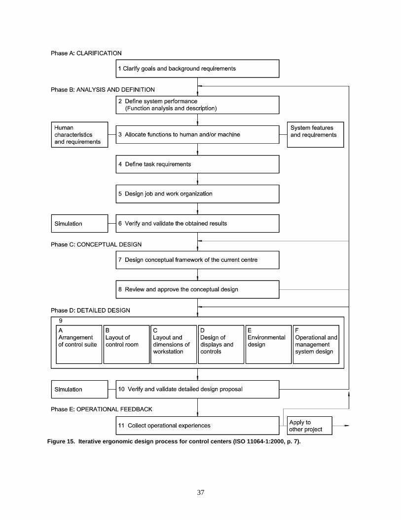
37
Figure 15. Iterative ergonomic design process for control centers (ISO 11064-1:2000, p. 7).
38
6.1.1.9 Framework for an ergonomic design process
As discussed in Principle 3 above, project staff should use an iterative design process in which they refine the design of the control center across multiple iterations. ISO 11064-1:2000 describes this iterative process in five phases: Clarification, Analysis and definition, conceptual design, detailed design, and operational feedback, as depicted in Figure 15. Each of these phases is discussed briefly in the following sections. Phase A: Clarification
The first phase in the iterative design process involves the first step of the iterative design process: clarification of the objectives, purpose, context, resources, constraints, and requirements of the design of the control center, referencing any applicable existing situations. In this phase, the design team identifies and documents the role of the control center and its relationships with other relevant systems or subsystems/components, including the descriptions and functions of the subsystems. The primary focus of this phase is the clarification of goals and background requirements, such as user requirements, regulatory requirements, operational feedback, and analysis of existing systems (ISO 11064-1:2000, p 6-9). Phase B: Analysis and definition
The second phase in the iterative design process involves multiple steps and has multiple objectives. Primarily, the focus of Phase B is to analyze the control center’s functional and performance requirements, and to produce a preliminary function allocation and job design. The steps of Phase B are as follows (note that Step 1 is part of Phase A): Step 2: define system performance (function analysis and description). Step 3: allocate functions to human and/or machine. Step 4: define task requirements. Step 5: design job and organization. Step 6: verify and validate the obtained results (ISO 11064-1:2000, p 10).
ISO 11064-1:2000 provides a detailed description of each of these steps, discussing the scope, potential methods that may be used, and the outputs of each step. In Step 2, a functional analysis is to be conducted to identify the specific ergonomic needs and solutions required to achieve the objectives defined in Phase A. The scope of this functional analysis should encompass all anticipated operational modes of the system, the analysis may employ techniques such as real or postulated walk-throughs or talk-throughs of operational modes, evaluation of operational safety and reliability requirements, top-down functional process diagrams, bottom-up function analysis, etcetera, and the output of the functional analysis are a list of system performance requirements and functions associated with the overall goals of the system (ISO 11064-1:2000, p 9-10). The function analysis as applied to an OCC project is described in Section 3.2 above. In Step 3, the performance requirements identified in Step 1 are allocated to humans, machines, or a combination of both humans and machines. This step identifies the functions that are to be performed by humans, the functions that are to be performed by machines (along with requirements for error-tolerant system design), and the interactions between the humans and the machines (ISO 11064-1:2000, p 10). While function allocation is crucial for automated systems, it is nevertheless still important for outage control applications. For example, the process of providing status updates on ongoing work can be (and often is) allocated to humans (done via meetings, phone calls, and white boards), or it can be allocated to a machine, such as a communication software package that permits real-time updates from multiple
39
locations (e.g., the collaboration software described in Section 4.2.2). ISO11064-1:2000 provides an overview method and references to other allocation methods in Annex B of the same part. Extensive literature is available on function analysis and allocation; see Hugo et al. (2013) and Hugo et al. (2012) for overviews of the function allocation research and approaches. In Step 4, the team conducts a task analysis to determine the aspects of the tasks that are allocated to the humans in Step 3, including cognitive and manual activities, task frequency, complexity, communication requirements, etcetera, as well as preliminary engineering solutions based on experience or opportunities for evaluation. The team can use studies, walk-throughs, talk-throughs, and surveys, or other formal task analysis methods. The task analysis should be well-documented and identify the tasks to be performed to meet functional requirements and all associated human factors or ergonomic performance requirements. (ISO 11064-1:2000, p 13-15). In Step 5, the team should assign tasks to particular roles according to the planned work organization. This is done by defining a tentative work organization that satisfies user and regulatory requirements, defining job assignment criteria and jobs to be carried out by each operator, and should consider operator physical and cognitive abilities as well as social aspects of the work organization. The outputs of Step 5 are the jobs assigned to each operator, the work organization, requirements for communication between the operators and with personnel external to the control center, requirements for procedures, training, and information and control (ISO 11064:1-2000, p 15). This may be a more formal approach than can be supported for outage control center projects, which may not have a specific organizational structure or firm staffing requirements. This approach should be handled flexibly enough to accommodate the specific needs of the OCC improvement project and expected outage control teams. In Step 6, the team performs an intermediate verification and validation of the work done in prior steps with the project sponsors/owners and the users. The emphasis should be on verifying and validating all of the individual allocations, identifying all conflicts between the various requirements, and obtaining the endorsement of the users before moving on to Phase C (ISO 11064-1:2000, p 16-17). Phase C: Conceptual design
The purpose of Phase C is to develop a comprehensive design of the control center that meets the function allocation, task requirements, job descriptions, and organizational plans established in Phase B. The conceptual design should include the physical attributes of the control center, furnishings and amenities (e.g., restrooms, kitchen areas, meeting rooms), as well as the proposed HSI, including the displays, controls, communications, and multimedia applications (ISO 11064-1:2000). Phase C involves two steps: Step 7: Design conceptual framework of the control centre. Step 8: Approve the conceptual design.
Step 7 systematically restructures the results of previous steps into a series of design concepts and preliminary specifications that encompass all intended aspects of the control center’s characteristics. In this step, the team should define the criteria for device selection, design policy, and design criteria that conform to user and formal requirements. The outputs of this step include conceptual design specifications, including preliminary layouts, identification of significant known design constraints such as safety, budget, location, materials, etcetera, and an estimate of resource requirements to complete design specifications (ISO 11064-1:2000, p 17-18). See ibid for additional information. Step 8 is the critical step for approving the conceptual design by the project owners and end users. This step provides a final opportunity to review, verify, and make any modifications to the design of the
40
control center. Accordingly, this step should be viewed as a major milestone for the project that “enables subsequent detailed design to proceed with a minimum risk of major functional revisions and physical changes” (ISO 11064-1:2000, p 19). Phase D: Detailed design
The purpose of Phase D is to develop the detailed design specifications for the control center, which shall be detailed sufficiently to enable estimating and planning of the construction, remodeling, or repurposing of an existing facility. The design specifications also need to be detailed enough to enable estimates and initiating requests for quotations from vendors or contractors for all purchased furnishings, systems software, tools, etcetera (ISO 11064-1:2000, p 19). Phase D involves two steps, the first of which has multiple substeps that should occur in an order that makes sense for the particular design project: Step 9: Detailed design.
o Control suite arrangement. o Control room layout. o Workstation layout and dimensions. o Design of displays and controls. o Environmental design. o Operational and management systems design.
Step 10: Verify and validate detailed design proposal. ISO 11064-1:2000 provides high level guidance on Step 9, but other standards provide more detailed information to inform this phase of the design project. ISO 11064-2:2000 provides standards for the arrangement of control suites and is discussed in Section 6.1.2 of this report. ISO 11064-3:1999 provides standards for control room layout, and is also discussed in Section 6.1.2 of this report. ISO 11064-4 and ANSI/HFES-100 provide standards for the layout and design of workstations. Environmental design refers to aligning the proposed design specifications with regards to a safe and comfortable working environment, including consideration of the thermal environment, air distribution, air composition, the lighting, acoustic environment, and vibrations (ISO 11064-1:2000, p 23). Operational and management systems design involves developing detailed solutions for the operation and management of the control center, including considerations of such topics as training organization, maintenance organization, shift patterns, user requirements including company policies and cultural factors, the potential need for contacts with other groups outside of the control room, and communication requirements (ISO 11064-1:2000, p 23). Step 10 involves a final, formal detailed design review with the users, project owners, and the project team to verify that the final design conforms to the design specifications used in Step 9. The objective of Step 10 is final approval of the detailed design specifications. ISO 11064-1:2000 emphasizes that verification and validation should be an iterative process that is integrated within the design process. Validation criteria, results, and user feedback should be documented throughout the design process. Phase E: Operational feedback
Once the control center is complete and operations begin, operational feedback remains needed to continue checking on the validity of the design of the control center throughout its lifespan. This is accomplished by collecting and examining operational feedback after the center begins operation. This step involves collection of information such as operational practice or experience, accident or deviation
41
reports, operation logs, and can involve methods such as field observations, interviewing users, surveys, and task analyses (ISO 11064-1:2000, p 24). The above design process, while possibly more rigorous than necessary for an outage control center design project, is nevertheless instructive for the steps that should be at least considered in the design of an outage control center. As previously mentioned, while an OCC does not control a physical, nuclear, hydraulic, or thermodynamic process, it does control human, maintenance, modification, and scheduling processes, and the approach to designing the former kinds of systems is still applicable to the approach needed for designing the latter human systems. An OCC that is designed with the needs of the outage management staff and the outage process in mind will prove beneficial to the outage control process, and in our experience, the budget and duration of the outage process.
6.1.2 Principles for the Arrangement and Layout of the Control Room/Suite
The ISO distinguishes between three types of control facilities: control rooms, control suites, and control centres. According to the ISO definition, a control room is the core functional entity and its associated physical structure, where operators are stationed to carry out centralized control, monitoring and administrative responsibilities (ISO 11064-3:1999, definition 3.4). A control suite is a group of functionally related rooms, co-located with the control room and including it, which houses the supporting functions to the control room, such as related offices, equipment rooms, rest areas, and training rooms (ISO 11064-3:1999, definition 3.6). A control centre is a combination of control rooms, control suites, and local control stations that are functionally related and all on the same site (ISO 11064-3:1999, definition 3.1). Figure 15 provides a visual representation of the differences between control rooms, control suites, and control centres. Outage Control Centers will not typically require more than one control room, but they will commonly require related offices, conference rooms, and workspaces. Therefore, the ISO definition most applicable to this situation is that of a control suite. ISO Standard 11064-2:2000 provides specific guidance for the arrangement of control suites, and ISO 11064-3:1999 provides standards for the design of control rooms. This section provides a high-level overview of these two standards.
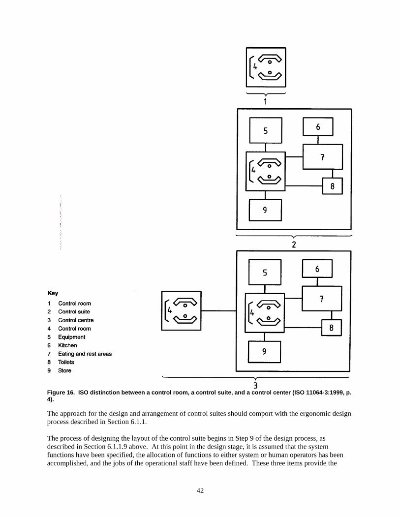
42
Figure 16. ISO distinction between a control room, a control suite, and a control center (ISO 11064-3:1999, p. 4).
The approach for the design and arrangement of control suites should comport with the ergonomic design process described in Section 6.1.1. The process of designing the layout of the control suite begins in Step 9 of the design process, as described in Section 6.1.1.9 above. At this point in the design stage, it is assumed that the system functions have been specified, the allocation of functions to either system or human operators has been accomplished, and the jobs of the operational staff have been defined. These three items provide the
43
information needed as a starting point for the design of the control suite, including a list of system functions, the work tasks, their relationships, length, frequency, and workload, the job of each member of the operating staff and the tasks assigned to each person, and a description of the equipment to be installed in the control suite (ISO 11064-2:2000, p 3-4). ISO 11064-2:2000 emphasizes that the specific application of this design process depends on whether a new facility is being constructed or an existing facility is being adapted or renovated. It may be the case that existing experience from a previous or comparable control center is not available. In this case, the project team should develop an overview of staffing level and work tasks, with more details to be developed as the design progresses. When updating an existing facility, the situation and task analyses conducted in Phase B should serve as the starting point. The team may replace a function analysis with “an overview of the current work tasks, in combination with an analysis of the constraints to be observed when proposing changes to the work organization” (ISO 11064-2:2000, p 4). The project team should also include the users directly in the design process.
6.1.2.1 Location of the control suite
Depending on the specific OCC project, the project team may be designing a completely new facility to be constructed on a site, remodeling an existing structure, or simply adapting an existing facility without extensive construction or remodeling. ISO 11064-2:2000 provides a number of interacting ergonomic, environmental, and technical aspects that need to be considered when determining the location of a control center. These are most relevant to new construction, but are still worth consideration when working on an OCC project that does not involve extensive remodeling. Ergonomic aspects to consider (ISO 11064-2:2000, p 4): Visibility requirements (e.g., if it is important that a location or process is visible, the control
center should be located such that visual observation is unencumbered). Distances between the control suite, the local control rooms, and local workstations. Control suite accessibility and emergency exits. Job and work organization design proposals, including communication and interpersonal
interaction requirements. User interaction with equipment. The movement of operators, other personnel, and visitors within the control suite. Adequate space necessary for service and maintenance activities.
Environmental aspects to consider (ISO 11064-2:2000, p 4): Lighting and windows. Control of room temperature. Protection against or avoidance of high noise levels. Protection against or avoidance of draught, wind, dust, and toxic hazards. Protection against or avoidance of vibrating environments. Minimizing the exposure to of alternating electromagnetic fields of external equipment (see ISO
11064-6 for further information). Technical aspects to consider (ISO 11064-2:2000, p 5): Civil construction of a building. Relationships between process units, areas to be guarded, locations of work to be supervised,
etcetera. Pipe, cable, and duct routing.
44
Accommodation for future expansion. Other aspects to consider (ISO 11064-2:2000, p 5): Safety aspects (e.g., whether the control suite is to be used as an emergency shelter, whether
blast-proofing is needed, etcetera). Security, access to the public, security checks and gates. Public relations. Control suite visibility for reasons of security or public relationships. Architecture, how the building fits into the surrounding environment.
For OCC projects, some of these considerations are more relevant than others (e.g., most ergonomic and environmental aspects are highly relevant, whereas architecture may not be as important), but the specific project needs will vary based on the individual circumstances, whether new construction is involved, whether the utility is concerned with the appearance of the building, and so on. Each project should identify the considerations that are relevant to the specific circumstances of the project.
6.1.2.2 Overview of task zones in the control suite
It is very important for the design team to consider and develop task zone requirements for the control suite; i.e., the team should consider what work needs to be done and where in the control room or control suite that work is best located. The design specification for task zones should include (ISO 11064-2:2000, p 5): The number of users per room as well as variability in numbers. Estimated sizes and space requirements of fully equipped workstations per room . Consideration of requirements for shift turnover and team briefings. Location of noise sources (e.g., printers, phones, alarms). Space allowances for future modifications or extensions.
ISO 11064-2:2000 recommends an approach of specifying a task zone for each work task, with each task zone allocated to workstations. Depending on the specific project needs, certain task zones can be organized in one room (e.g., all control and supervision tasks in one room, and rest activities in another room). Alternatively, certain task zones can be merged, if the same person performs both tasks at the same workstation, or a single room can be dedicated to a single task (ISO 11064-2:2000, p 5).
6.1.2.3 Design of the layout of the control suite
The design team should base the functional design of the control suite on the overview and requirements of each of the task zones, considering important aspects such as tasks that require links between task zones, access to the task zones, environmental constraints (e.g., positioning of computer screens in relation to windows to minimize glare), and equipment housing and maintenance access (ISO 11064-2:2000, p 6).
6.1.2.4 Additional ergonomic aspects to be considered
ISO 11064-2:2000 also provides additional discussion on the following ergonomic principles that must be included when designing the arrangement of a control suite (p 7-10):
45
Communication
Task zones of individuals requiring frequent verbal communication should be located close to each other.
Control suite equipment should facilitate visual contact between operators wherever is needed. Communications that are extraneous to control suite functions should not distract personnel. Locations with different functions should be physically separated to avoid potential sources of
disturbance (ISO 11064-2:2000, p 7-8). Traffic and routing
Distances should be minimized to account for travel and communication needs. If there is a need to directly and visually monitor a certain part of the site, the workplace for this
monitoring task determines the location of the control suite on the site. Any restrictions for unauthorized personnel should not impede authorized personnel. Special consideration should be made to avoid undesirable walking routes such as short cuts
through emergency exits. The layout of the site should permit easy access to all areas that may legitimately need to be visited.
It should be possible, from a normal position, for operators to observe persons entering and exiting a room with minimum distraction (this is important for both security and personal comfort considerations) (ISO 11064-2:2000, p 8).
Entrances and exits
Doors and passageways in the control suite should be of adequate size and layout to enable passage of all control suite furnishings and equipment.
Account for space required to supervise the entrance. Ready access to first aid equipment, emergency equipment, and emergency exits should be
included (ISO 11064-2:2000, p 8). Environmental conditions
Materials used for floors, walls, and ceilings should minimize glare, reflections, and large contrasts. Where needed, noise should be minimized by appropriate means.
Potential sources of disturbances should be identified and considered, and the location of the control room should be planned in such a way that these disturbances are minimized.
The location of the control suite should be chosen to minimize possible risk of exposure to hazards (ISO 11064-2:2000, p 8).
Cleaning
ISO 11064-2:2000 (p 9) recommends the use of durable building or construction materials that require minimal cleaning and are easy to clean.
Provisions should be made to minimize dirt in the control suite. Storage and use of cleaning agents should not present a risk to personnel from fumes or contact.
Maintenance
It should be possible to perform maintenance in the control room with the minimum disturbance to the operation of the control suite.
Equipment and workstations should be easily accessible for maintenance purposes.
46
Cabling, ventilation ducts, and the like should be properly concealed but easily accessible, and possible future expansions of cabling should be considered in the design (ISO 11064-2:2000, p 9).
Visitors
Consider both the presence of public and professional visitors and the differing needs of both. Public visitors should be given guided tours of the facility that are designed to minimize potential
distractions to the control center staff. Facilities should be created for adequate reception of public visitors outside of the central control room.
The control center should be designed such that professional visitors can view all displays without unnecessary distraction to the control room operators.
Space for visitor safety shoes, helmets, etcetera, should be considered and provided if necessary for the facility (ISO 11064-2:2000, p 9).
Operator supporting information
When information necessary for operator support is in document form (e.g., drawings, procedures, manuals, etcetera) that is stored either on paper or via electronic systems, the information should be stored and structured in such a way that information used frequently can be easily retrieved.
Filing and storage facilities should be adequate for the volume of material. Special provision should be made for easy access to material that is required in emergencies. The use of computer-assisted documentation should be considered and used where possible to
save space and speed up research, particularly for emergency procedures (ISO 11064-2:2000, p 9-10).
6.1.2.5 Verification and validation of layout of the control suite
The final verification and validation of the control suite layout should be performed consistent with Phase D of the design process, discussed in 6.1.1.9 above. Specific to the layout of the suite, the project team should do the following (ISO 11064-2:2000, p 10): Compare the design features to the design criteria to ensure compliance. Ensure that validation is operationally realistic. Evaluate functions and usability. Validate traffic patterns and communication links (can be done with link analysis). Use walk-through and talk-through techniques with the objective of working though scenarios
and sequences in the new design. Use simple representations of the new design (e.g., drawings, photographs, mockups, virtual
reality techniques, etcetera). Use different task analysis techniques that enable testing of communication and coordination
(e.g., link analysis or timeline analysis). Apply the principles for the evaluation of control centers as provided in ISO 11064-7.
6.1.2.6 Additional considerations
The above guidelines provide overarching principles to apply during the design of a control suite. While the above ISO guidelines briefly mention certain issues that are relevant for OCC projects, some additional discussion of OCC-specific needs is warranted.
47
Restrooms and break or rest areas
The OCC should either have its own restroom facilities in the center, or restrooms should be located a short distance from the OCC. When constructing a new OCC, the location of the restrooms should be included within the boundaries of the control suite. OCC staff should not have to go through security checkpoints to reach a restroom. The design of an OCC should also consider the need for break areas or break rooms, kitchens and common areas. OCC staff should have access to ice, water, and vending services, within reason. Even if the site provides a cafeteria, OCC staff should have ready access to a refrigerator and means of heating up food. For many facilities, having a break room with a single kitchenette wall that contains a refrigerator, microwave, and a sink will be sufficient. New OCC construction projects should include such a break/kitchen area in the design of the facility. For projects that involve updating an existing facility, care should be taken to enable staff to have easy access to their food within their allotted break times. Conference rooms and huddle rooms
Through the process of identifying the functions of the control center, the OCC project team should ensure that accommodations are made for OCC personnel to have conversations and meetings away from the primary control room. The OCC design should therefore consider including a large conference room that can accommodate the entire OCC staff at once, as well as smaller conference or huddle rooms where smaller groups can work together on specific tasks. All conference rooms should be equipped with displays and network connectivity or WiFi to permit viewing the status of ongoing work.
6.1.3 Control Room Layout (ISO 11064-3:1999)
The layout of the primary control room is dictated by the function and task analyses of the design process discussed in Section 6.1.1.9 above. ISO 11064-3:1999 provides the standards for the layout of control rooms; some aspects of this standard are duplications of guidance already discussed or provided in other standards, and other aspects do not apply to the OCC application. This section overviews the parts of this standard that should be considered in designing the primary outage control room. Generally, the design of the primary outage control room should comport with the above design guidance and iterative design process. ISO 11064-3:1999 provides guidance on the arrangement of workstations within the control room, and provides minimum space for personnel circulation, wheelchair clearance, and maintenance activities. Specifically, ISO 11064-3:1999 identifies the following items that must be considered in the design of the control room layout (excerpted from p 13): Operational links between the control room operators, such as lines of sight and communication
should be documented using link association tables prior to developing the control workstation layouts.
When considering alternative ways of laying out multiple control workstations, consider whether control workstations are dedicated to individual operators or are shared, whether each workstation is identical, and whether all operations can be carried out from a single workstation or tasks must be spread amongst a number of workstations.
Control workstation arrangements should account for normal, abnormal, and emergency modes of system operation.
Position workstations to avoid glare, reflections, and draughts. Social contact within the control room (e.g., conversations unrelated to operation of the control
room) should be enabled to occur without compromising operator efficiency.
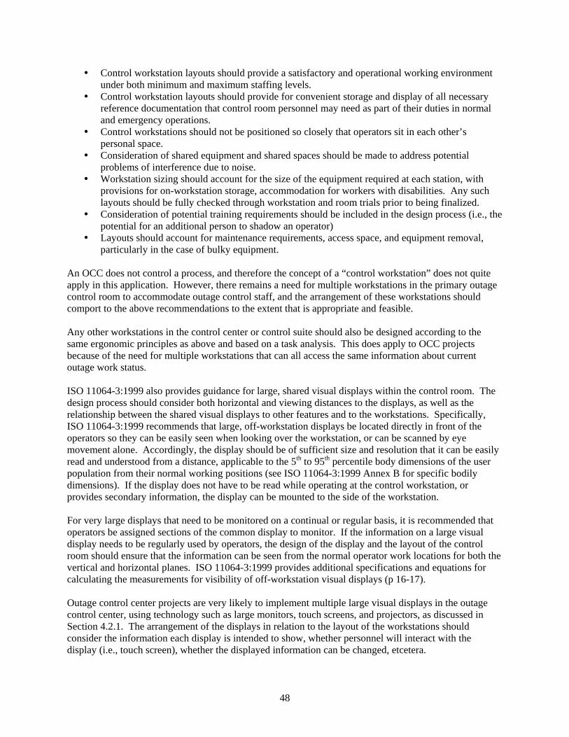
48
Control workstation layouts should provide a satisfactory and operational working environment under both minimum and maximum staffing levels.
Control workstation layouts should provide for convenient storage and display of all necessary reference documentation that control room personnel may need as part of their duties in normal and emergency operations.
Control workstations should not be positioned so closely that operators sit in each other’s personal space.
Consideration of shared equipment and shared spaces should be made to address potential problems of interference due to noise.
Workstation sizing should account for the size of the equipment required at each station, with provisions for on-workstation storage, accommodation for workers with disabilities. Any such layouts should be fully checked through workstation and room trials prior to being finalized.
Consideration of potential training requirements should be included in the design process (i.e., the potential for an additional person to shadow an operator)
Layouts should account for maintenance requirements, access space, and equipment removal, particularly in the case of bulky equipment.
An OCC does not control a process, and therefore the concept of a “control workstation” does not quite apply in this application. However, there remains a need for multiple workstations in the primary outage control room to accommodate outage control staff, and the arrangement of these workstations should comport to the above recommendations to the extent that is appropriate and feasible. Any other workstations in the control center or control suite should also be designed according to the same ergonomic principles as above and based on a task analysis. This does apply to OCC projects because of the need for multiple workstations that can all access the same information about current outage work status. ISO 11064-3:1999 also provides guidance for large, shared visual displays within the control room. The design process should consider both horizontal and viewing distances to the displays, as well as the relationship between the shared visual displays to other features and to the workstations. Specifically, ISO 11064-3:1999 recommends that large, off-workstation displays be located directly in front of the operators so they can be easily seen when looking over the workstation, or can be scanned by eye movement alone. Accordingly, the display should be of sufficient size and resolution that it can be easily read and understood from a distance, applicable to the 5th to 95th percentile body dimensions of the user population from their normal working positions (see ISO 11064-3:1999 Annex B for specific bodily dimensions). If the display does not have to be read while operating at the control workstation, or provides secondary information, the display can be mounted to the side of the workstation. For very large displays that need to be monitored on a continual or regular basis, it is recommended that operators be assigned sections of the common display to monitor. If the information on a large visual display needs to be regularly used by operators, the design of the display and the layout of the control room should ensure that the information can be seen from the normal operator work locations for both the vertical and horizontal planes. ISO 11064-3:1999 provides additional specifications and equations for calculating the measurements for visibility of off-workstation visual displays (p 16-17). Outage control center projects are very likely to implement multiple large visual displays in the outage control center, using technology such as large monitors, touch screens, and projectors, as discussed in Section 4.2.1. The arrangement of the displays in relation to the layout of the workstations should consider the information each display is intended to show, whether personnel will interact with the display (i.e., touch screen), whether the displayed information can be changed, etcetera.
49
Additionally, the control room layout must account for circulation of personnel (and afford interactive wall displays space for users accordingly) and ensure that control operations are not interrupted by visual or auditory distraction. The control room layout shall accommodate wheelchair users, allowing for the maximum width of the largest wheelchair, clearances for elbows to propel the chair, and additional space for turning (ISO 11064-3:1999 provides some guideline dimensions; see page 19). Particular care should be taken to provide for adequate circulation during shift turnover, when two shifts are present at the same time. Additionally, the layout of the control room shall accommodate orderly evacuation of the room and avoid pinch points. ISO 11064-3:1999 provides equations for the minimum dimensions of circulation space for emergency and non-emergency exits based on bodily dimension and other factors (see p. 18).
6.1.4 Ergonomic Principles for Workstations
The ergonomic principles for workstations are the standards with which people tend to be the most familiar. This involves principles such as the height of the desktop, height of the keyboard, mouse, or other input devices, the size, position, and height of workstation displays, and the adjustability of the workstation chair. Many workplaces are installing adjustable-height desks or workstations so their staff can sit or stand while working. However, this may not be an appropriate option for an outage control center: desks that are raised to standing height are likely to impede the ability to see large display panels on the OCC walls. Therefore, height-adjustable desks are not recommended within the OCC control room. The workstation displays, height, keyboards and other input devices should meet ergonomic requirements, and workstation chairs should be ergonomically adjustable. See ISO 11064-4:2004 and ANSI/HFES-100 for more details. If any tasks identified in the function and task analysis require specialized input devices (e.g., track pads, touch pads and stylus), those devices should be included in the workstation design.
6.1.5 Design Principles for Operator Workload
ISO 10075-2:1996 provides standards for the design of work to account for operator cognition and workload capabilities. This standard is relevant to the design of outage control centers; outages are tremendously busy times, and outage personnel typically have very heavy workloads. It is important that the design of new (or upgraded) outage control centers and the systems within the control suite account for human cognitive capabilities to help minimize personnel workload. ISO 10075-2:1996 aligns well with the ergonomic, iterative design process described in Section 6.1.1 and 6.1.1.9 above, and the design of the work system should include concern for user workload requirements throughout the design process. ISO 11075-2:1996 provides design principles that are intended to minimize the intensity and duration of operator workload. As discussed in Section 6.1.1.9, work system design begins with a function analysis of the system, a function allocation of tasks to the system and operator, task analysis, and produces task design and allocation to the operator (ISO 11075-2:1996, p 2). Consideration of operator workload should be included in all discussions of tasks allocated to human operators. Mental workload is not a one-dimensional concept, but has both qualitative aspects as well as quantitative aspects (e.g., task load). “Mental workload can be described in terms of intensity, duration, and temporal distribution of the intensity in which the operator is exposed to the workload” (ISO 11075-2:1996, p 3). Additionally, there are qualitative differences in tasks that operators may have to perform that impact mental workload; e.g., perceptual-motor tasks versus tasks with high memory requirements. Simply focusing on under load, optimal load, and overload is insufficient to ensure optimal operator workload.
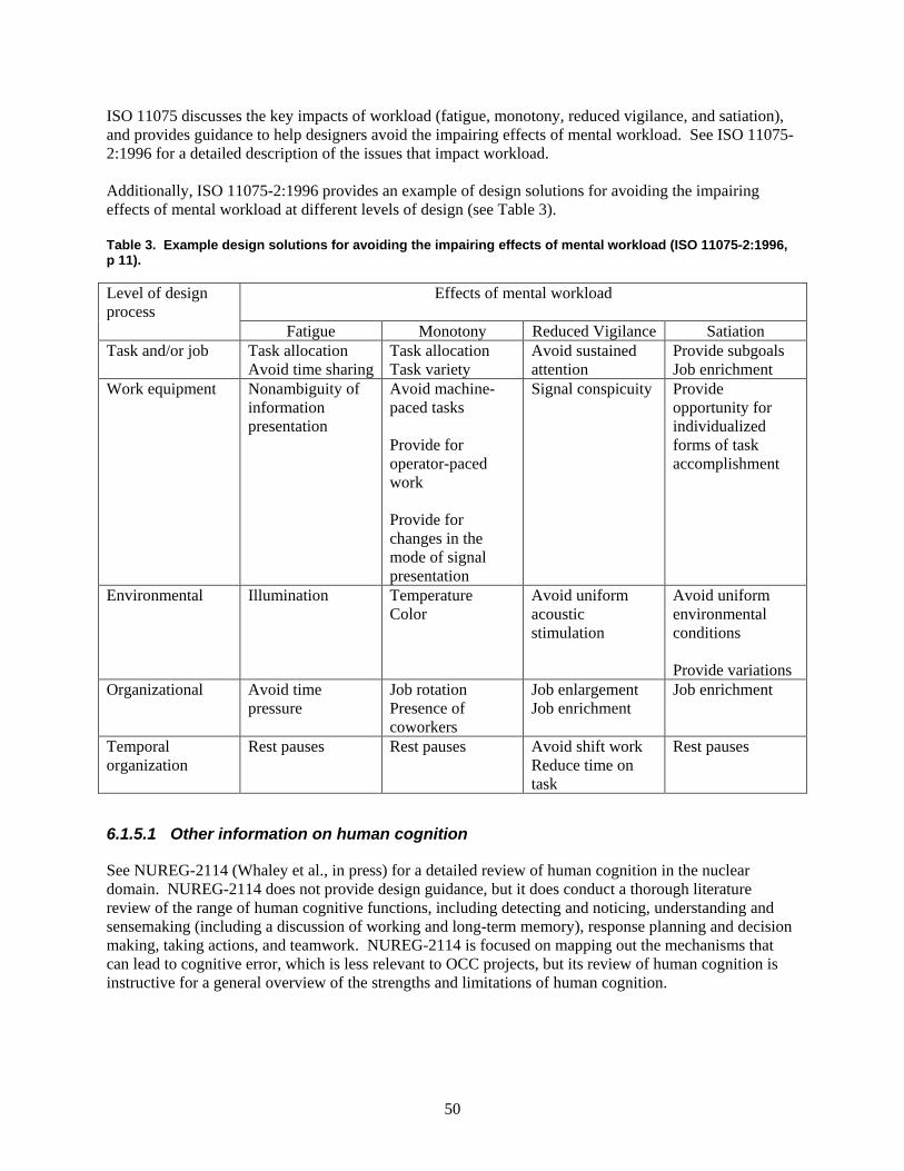
50
ISO 11075 discusses the key impacts of workload (fatigue, monotony, reduced vigilance, and satiation), and provides guidance to help designers avoid the impairing effects of mental workload. See ISO 11075-2:1996 for a detailed description of the issues that impact workload. Additionally, ISO 11075-2:1996 provides an example of design solutions for avoiding the impairing effects of mental workload at different levels of design (see Table 3). Table 3. Example design solutions for avoiding the impairing effects of mental workload (ISO 11075-2:1996, p 11).
Level of design process
Effects of mental workload
Fatigue Monotony Reduced Vigilance Satiation Task and/or job Task allocation
Avoid time sharing Task allocation Task variety
Avoid sustained attention
Provide subgoals Job enrichment
Work equipment Nonambiguity of information presentation
Avoid machine-paced tasks Provide for operator-paced work Provide for changes in the mode of signal presentation
Signal conspicuity Provide opportunity for individualized forms of task accomplishment
Environmental Illumination Temperature Color
Avoid uniform acoustic stimulation
Avoid uniform environmental conditions Provide variations
Organizational Avoid time pressure
Job rotation Presence of coworkers
Job enlargement Job enrichment
Job enrichment
Temporal organization
Rest pauses Rest pauses Avoid shift work Reduce time on task
Rest pauses
6.1.5.1 Other information on human cognition
See NUREG-2114 (Whaley et al., in press) for a detailed review of human cognition in the nuclear domain. NUREG-2114 does not provide design guidance, but it does conduct a thorough literature review of the range of human cognitive functions, including detecting and noticing, understanding and sensemaking (including a discussion of working and long-term memory), response planning and decision making, taking actions, and teamwork. NUREG-2114 is focused on mapping out the mechanisms that can lead to cognitive error, which is less relevant to OCC projects, but its review of human cognition is instructive for a general overview of the strengths and limitations of human cognition.
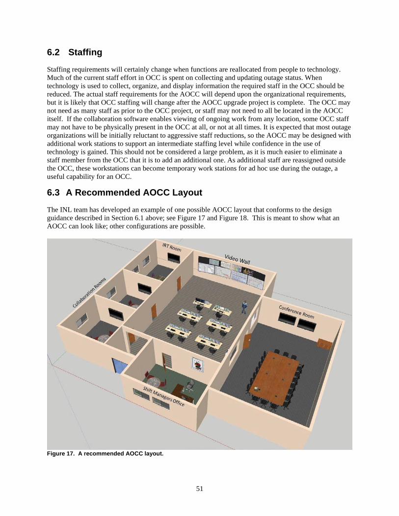
51
6.2 Staffing
Staffing requirements will certainly change when functions are reallocated from people to technology. Much of the current staff effort in OCC is spent on collecting and updating outage status. When technology is used to collect, organize, and display information the required staff in the OCC should be reduced. The actual staff requirements for the AOCC will depend upon the organizational requirements, but it is likely that OCC staffing will change after the AOCC upgrade project is complete. The OCC may not need as many staff as prior to the OCC project, or staff may not need to all be located in the AOCC itself. If the collaboration software enables viewing of ongoing work from any location, some OCC staff may not have to be physically present in the OCC at all, or not at all times. It is expected that most outage organizations will be initially reluctant to aggressive staff reductions, so the AOCC may be designed with additional work stations to support an intermediate staffing level while confidence in the use of technology is gained. This should not be considered a large problem, as it is much easier to eliminate a staff member from the OCC that it is to add an additional one. As additional staff are reassigned outside the OCC, these workstations can become temporary work stations for ad hoc use during the outage, a useful capability for an OCC.
6.3 A Recommended AOCC Layout
The INL team has developed an example of one possible AOCC layout that conforms to the design guidance described in Section 6.1 above; see Figure 17 and Figure 18. This is meant to show what an AOCC can look like; other configurations are possible.
Figure 17. A recommended AOCC layout.
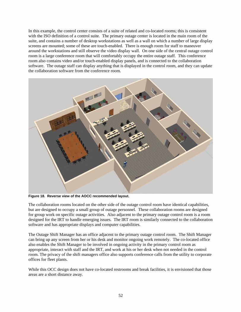
52
In this example, the control center consists of a suite of related and co-located rooms; this is consistent with the ISO definition of a control suite. The primary outage center is located in the main room of the suite, and contains a number of desktop workstations as well as a wall on which a number of large display screens are mounted; some of these are touch-enabled. There is enough room for staff to maneuver around the workstations and still observe the video display wall. On one side of the central outage control room is a large conference room that will comfortably occupy the entire outage staff. This conference room also contains video and/or touch-enabled display panels, and is connected to the collaboration software. The outage staff can display anything that is displayed in the control room, and they can update the collaboration software from the conference room.
Figure 18. Reverse view of the AOCC recommended layout.
The collaboration rooms located on the other side of the outage control room have identical capabilities, but are designed to occupy a small group of outage personnel. These collaboration rooms are designed for group work on specific outage activities. Also adjacent to the primary outage control room is a room designed for the IRT to handle emerging issues. The IRT room is similarly connected to the collaboration software and has appropriate displays and computer capabilities. The Outage Shift Manager has an office adjacent to the primary outage control room. The Shift Manager can bring up any screen from her or his desk and monitor ongoing work remotely. The co-located office also enables the Shift Manager to be involved in ongoing activity in the primary control room as appropriate, interact with staff and the IRT, and work at his or her desk when not needed in the control room. The privacy of the shift managers office also supports conference calls from the utility to corporate offices for fleet plants. While this OCC design does not have co-located restrooms and break facilities, it is envisioned that those areas are a short distance away.

53
This design is based on the INL team’s understanding of the needs of an AOCC, and is consistent with the Human Factors design principles discussed in Section 6.1.
54
7 CONCLUSIONS
In conclusion, this report provides guidance for the implementation of an Advanced Outage Control Center (AOCC). An AOCC is an OCC specifically designed to take advantage of advanced communication and collaboration technologies. This report provides a vision of an AOCC including descriptions of the various advanced outage functions it should support. This report provides guidance for any nuclear power plant (NPP) to either implement a new physical AOCC or to implement technology into an existing OCC to enhance the capabilities of the OCC to support outage management and staff. This report provides a process for implementation of a change management plan, evaluation of current outage processes, the selection of technology, and guidance for the implementation of the selected technology. Additionally, guidance is provided to incorporate human factors considerations into the design and layout of an OCC. This report also provides the results of implementation of these concepts at commercial NPPs in the US. These are not untested concepts; they have been demonstrated both at INL facilities and at utilities working with INL, primarily Palo Verde Nuclear Generating Station. Several additional utilities have reviewed the results of the initial technology implementations and determined their stations would benefit from similar technology implementations. The project team will continue to develop additional AOCC capabilities as well as further refine those that have already been implemented. As additional utilities implement these capabilities, the guidance provided in this report will also be refined to provide utilities interested in outage improvement as many lessons learned as possible related to implementation these concepts.
55
8 REFERENCES
Braseth, A. O., & Øritsland, T. A. (2013). Visualizing complex processes on large screen displays:
Design principles based on the Information Rich Design concept. Displays, 34, 215-212. doi:10.1016/j.displa.2013.05.002
Devgun, J. (2013). Managing modifications, power uprates and outages at operating nuclear power
plants. In J. Devgun (Ed.), Managing Nuclear Projects: A Comprehensive Management Resource. Cambridge, UK: Woodhead Publishing. doi:10.1533/9780857097262.2.115
Duval, C., Leger, A., Weber, P., Levrat, E., Lung, B., & Farret, R. (2007). Choice of a risk analysis
method for complex socio-technical systems. Proceedings of ESREL 2007, Stavanger, Norway, vol. 1, June 25-27, p. 17-25.
Gertman, D., & Blackman, H. (1994). Human Reliability and Safety Analysis Data Handbook. New York,
NY: John Wiley & Sons, Inc. Gertman, D., Blackman, H., Marble, J., Byers, J., & Smith, C. (2005). The SPAR-H Human Reliability
Analysis Method (NUREG/CR-6883). Washington, DC: U.S. Nuclear Regulatory Commission. Gregoriades, A., Sutcliffe, A., & Shin, J.-E. (2003). Assessing the reliability of socio-technical systems.
Systems Engineering, 6(3), 210-23. Hugo, J. (2012). Towards a Unified HFE Process for the Nuclear Industry. 8th International Topical
Meeting on Nuclear Plant Instrumentation, Control and Human Machine Interface Technologies, NPIC&HMIT 2012, San Diego, CA, July 22- 26.
Hugo, J., & Gertman, D. (2012). A Multi-Methods Approach to HRA and Human Performance
Modeling: A Field Assessment. In: PSAM 11 and ESREL 2012 Conference on Probabilistic Safety Assessment, June 25-29, 2012, Helsinki, Finland.
Hugo, J., Gertman, D., Joe, J., Medema, H., Whaley, A. M., & Farris, R. (2013). Development of a
Technical Basis and Guidance for Advanced SMR Function Allocation (INL/EXT-13-30117). Idaho Falls, Idaho: Idaho National Laboratory.
International Organization for Standardization (ISO) (2000). Ergonomic design of control centres—Part
1: Principles for the design of control centres (ISO 11064-1: 2000). Geneva: Switzerland. International Organization for Standardization (ISO) (2000). Ergonomic design of control centres—Part
2: Principles for the arrangement of control suites (ISO 11064-2: 2000). Geneva, Switzerland. International Organization for Standardization (ISO) (1999). Ergonomic design of control centres—Part
3: Control room layout (ISO 11064-3:1999). Geneva, Switzerland. International Organization for Standardization (ISO) (1999). (ISO 11064-3:1999/Cor 1:2002) International Organization for Standardization (ISO) (2013). Ergonomic design of control centres—Part
4: Layout and dimensions of workstations (ISO 11064-4:2013)
56
International Organization for Standardization (ISO) (2008). Ergonomic design of control centres—Part 5: Displays and controls (ISO 11064-5:2008). Geneva, Switzerland.
International Organization for Standardization (ISO) (2005). Ergonomic design of control centres—Part
6: Environmental requirements for control centres (ISO 11064-6:2005). Geneva, Switzerland. International Organization for Standardization (ISO) (2006). Ergonomic design of control centres—Part
7: Principles for the evaluation of control centres (ISO 11064-7:2006). Geneva, Switzerland. International Organization for Standardization (ISO) (1996). Ergonomic Principles Related to
Workload—Part 2: Design Principles (ISO 10075-2:1996). Geneva, Switzerland. International Organization for Standardization (ISO) (1991). Ergonomics principles related to mental
workload—Part 1: General terms and definitions (ISO 10075:1991). Geneva, Switzerland. International Organization for Standardization (ISO) (2004). Ergonomics principles related to mental
workload—Part 3: Principles and requirements concerning methods for measuring and assessing mental workload (ISO 10075-3:2004). Geneva, Switzerland.
Johansen, R., Groupware: Computer Support for Business Teams, New York: The Free Press, 1988. Kolaczkowski, A., Forester, J., Lois, E., & Cooper, S. (2005). Good Practices for Implementing Human
Reliability Analysis (HRA) (NUREG/CR-1792). Washington, DC: U.S. Nuclear Regulatory Commission.
Kotter, J (2002). The Heart of Change. Cambridge, MA: Harvard Business School Press. O’Hara, J. M., Higgins, J. C., Persensky, J. J., Lewis, P. M., & Bongarra, J. P. (2004). Human Factors
Engineering Program Review Model (NUREG-0711). Washington, DC: U.S. Nuclear Regulatory Commission.
Van Laar, D., & Deshe, O. (2007). Color coding of control room displays: The psychocartography of
visual layering effects. Human Factors, 49(3), 477-490. doi:10.1518/001872007X200111 Whaley, A. M., Xing, J., Boring, R. L., Hendrickson, S. M. L., Joe, J. C., & Le Blanc, K. L. (in press).
Building a Psychological Foundation for Human Reliability Analysis (NUREG-2114). Washington DC: U.S. Nuclear Regulatory Commission.
Wiczorek, R., & Manzey, D. (2014). Supporting attention allocation in multitask environments: Effects
of likelihood alarm systems on trust, behavior, and performance. Human Factors, first published on March 31, 2014. doi:10.1177/0018720814528534
Woods, D. D., Johannesen, L. J., Cook, R. I., & Sarter, N. B. (1994). Behind Human Error: Cognitive
Systems, Computers, and Hindsight (CSERIAC-SOAR 94-01). Wright-Patterson Airforce Base, Ohio: Crew Systems Ergonomics Information Analysis Center.
Zio (2009). Reliability engineering: Old problems and new challenges
57
APPENDICES
Appendix A: Palo Verde Case Study Appendix B: Plant Farley Case Study Appendix C: Advanced Test Reactor Case Study Appendix D: Data Collection Forms Appendix E: Change Management Checklist Guide Appendix F: Strategic Change Management Checklist Appendix G: Tactical Change Management Checklist Appendix H: Communication Plan (Template)
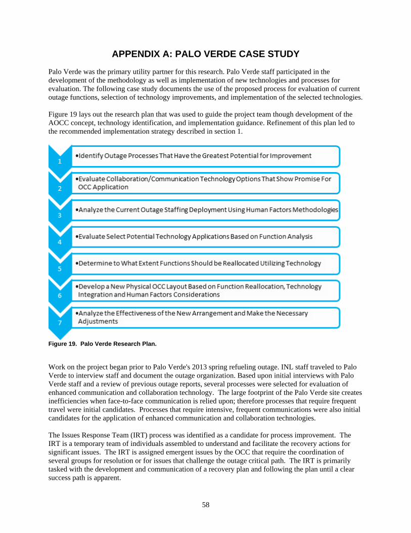
58
APPENDIX A: PALO VERDE CASE STUDY
Palo Verde was the primary utility partner for this research. Palo Verde staff participated in the development of the methodology as well as implementation of new technologies and processes for evaluation. The following case study documents the use of the proposed process for evaluation of current outage functions, selection of technology improvements, and implementation of the selected technologies. Figure 19 lays out the research plan that was used to guide the project team though development of the AOCC concept, technology identification, and implementation guidance. Refinement of this plan led to the recommended implementation strategy described in section 1.
Figure 19. Palo Verde Research Plan.
Work on the project began prior to Palo Verde's 2013 spring refueling outage. INL staff traveled to Palo Verde to interview staff and document the outage organization. Based upon initial interviews with Palo Verde staff and a review of previous outage reports, several processes were selected for evaluation of enhanced communication and collaboration technology. The large footprint of the Palo Verde site creates inefficiencies when face-to-face communication is relied upon; therefore processes that require frequent travel were initial candidates. Processes that require intensive, frequent communications were also initial candidates for the application of enhanced communication and collaboration technologies. The Issues Response Team (IRT) process was identified as a candidate for process improvement. The IRT is a temporary team of individuals assembled to understand and facilitate the recovery actions for significant issues. The IRT is assigned emergent issues by the OCC that require the coordination of several groups for resolution or for issues that challenge the outage critical path. The IRT is primarily tasked with the development and communication of a recovery plan and following the plan until a clear success path is apparent.
59
Several processes that related to OCC functions were also identified as candidates for the application of technology. The OCC functions identified for technology evaluations include: tracking the readiness for retests and mode change, communication of work status into the OCC, communication of discovered conditions from the field to the OCC, and dissemination of information out of the OCC. Another communication-intensive process involves the function of the maintenance OCC (MOCC) satellite organization. The MOCC receives updates several times per shift from the individual maintenance shops regarding work status. These updates are currently conducted via face-to-face communication and require stakeholders to travel to the MOCC from various locations around the site. Communication and collaboration technology would allow these updates to occur remotely, saving transit time and allowing staff to focus on outage execution for their respective areas. INL research staff visited Palo Verde to observe outage activities during their 2013 spring refueling outage. The purpose of these visits was to gather data to support a function and task analysis of the OCC and to assess human factors aspects of the physical OCC layout. At this point, no technology implementations had been made, so a baseline could be established. Following the spring refueling outage, the project team determined the IRT was the best place to start. The standard issues package described in section 4.2.2.2 was developed and demonstrated for Palo Verde Staff prior to their 2013 fall outage. Palo Verde installed large format touch screens to support the IRT. MS OneNote was selected as the collaboration software as it was already approved for use on Palo Verdes business network. The standard issues package templates where built and training conducted with IRT staff prior to the start of the outage. The new technology supported IRT process was used throughout the 2013 fall outage. Initial response from the staff was positive, the technology was observed to improve issue coordination, communication to the OCC, shift turnover, knowledge management. The process was tested heavily when an emergent issue related to a leak on a bottom mounted instrumentation penetration was discovered. This complex issue involved nearly every group on site and several vendors. The standard issues package was used to coordinate and document every aspect of the inspections, recovery planning, and repair including industry operating experience, materials, engineering, schedule impacts, and task assignments. A similar issue had previously occurred at another plant and required 72 days to repair. Palo Verde was able to complete repairs in 32 days. Palo Verde partially credits the use of these new tools in the effective resolution of this issue. Palo Verde submitted the use of the standard issues package to NEI as a top industry practice and won a 2014 NEI Top Industry Practice Process Award for this process improvement. Prior to their 2014 spring outage, Palo Verde installed additional communication and collaboration technology into their OCC. Palo Verde implemented the video wall shown in figure 11 in the unit 2 OCC. The video wall was comprised of six 42 inch monitors, four 70 inch monitors, and one 70 touch enabled display. The monitors where each driven by collaboration software supported PC and connected through a video switch that enabled any content to be displayed on any of the monitors. Each department maintained a status page through the collaboration software that could be viewed or updated from any network PC. The video wall also supported live video feeds from the turbine building, the refuel floor, and containment. Much of the information displayed in the OCC was previously displayed as static information only viewable from inside the OCC. With the use of collaboration software, status is viewable from any network PC. The volume of phone calls and status requests to the OCC has been reduced due to the increased access to this information. Palo Verde outage management has been very satisfied with the results of the OCC technology improvements and intends to continue. INL staff will continue to work with Palo Verde to implement

60
more technology supported capability. The progression of technology implementation at Palo Verde is an excellent example of the step-wise technology deployment strategy described in section 5.1
61
APPENDIX B: PLANT FARLEY CASE STUDY
Southern Company’s Plant Farley is in the process of adopting several AOCC technologies. INL researchers visited Plant Farley in July 2014 to access if the technologies implemented at Palo Verde would be easily adaptable by other utilities. Plant Farley outage staff determined that several of the AOCC technologies and concepts could be easily adopted and initiated a project to implement them prior to the Unit 2 outage in fall 2014. INL staff worked with Plant Farley staff to modify MS OneNote templates used by Palo Verde for emergent issues response and OCC outage status management for use at Plant Farley. Plant Farley will also introduce the use of Sharepoint to host the OCC outage status templates to facilitate the use of tablet computers to allow outage management the ability to view and modify OCC status displays from any location on site (within WiFi coverage). INL staff will visit Plant Farley during their upcoming outage to evaluate their implementation of the AOCC concepts, especially the use of tablet computer as a mobile OCC status tool. Southern Company has already expressed interest in migrating lessons learned at Plant Farley to their other fleet assets. This will allow INL staff the opportunity to evaluate the knowledge transfer of AOCC concepts between fleet plants.
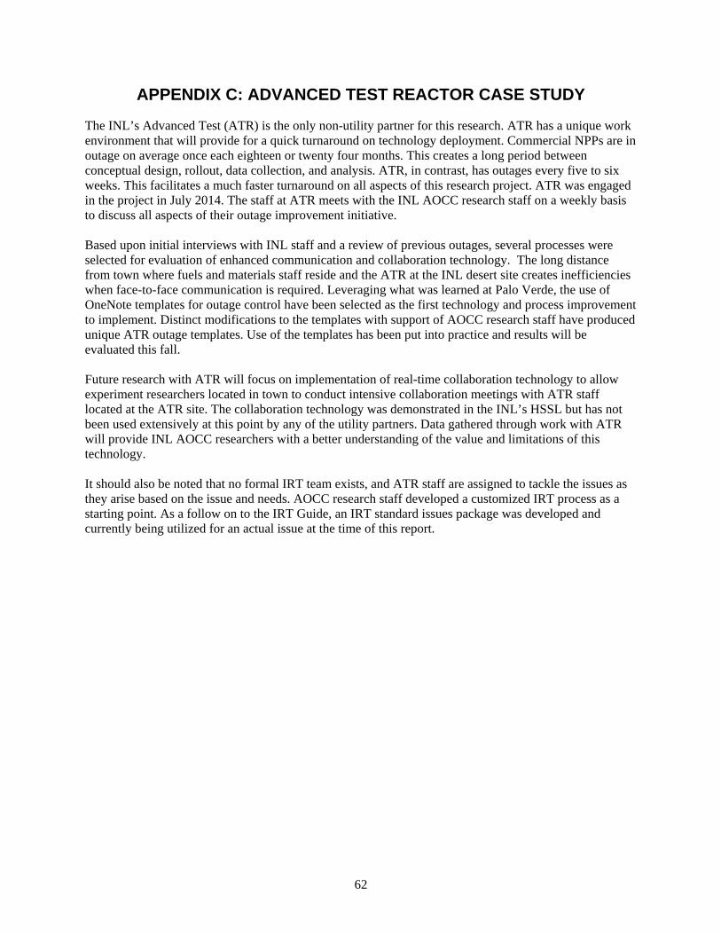
62
APPENDIX C: ADVANCED TEST REACTOR CASE STUDY
The INL’s Advanced Test (ATR) is the only non-utility partner for this research. ATR has a unique work environment that will provide for a quick turnaround on technology deployment. Commercial NPPs are in outage on average once each eighteen or twenty four months. This creates a long period between conceptual design, rollout, data collection, and analysis. ATR, in contrast, has outages every five to six weeks. This facilitates a much faster turnaround on all aspects of this research project. ATR was engaged in the project in July 2014. The staff at ATR meets with the INL AOCC research staff on a weekly basis to discuss all aspects of their outage improvement initiative. Based upon initial interviews with INL staff and a review of previous outages, several processes were selected for evaluation of enhanced communication and collaboration technology. The long distance from town where fuels and materials staff reside and the ATR at the INL desert site creates inefficiencies when face-to-face communication is required. Leveraging what was learned at Palo Verde, the use of OneNote templates for outage control have been selected as the first technology and process improvement to implement. Distinct modifications to the templates with support of AOCC research staff have produced unique ATR outage templates. Use of the templates has been put into practice and results will be evaluated this fall. Future research with ATR will focus on implementation of real-time collaboration technology to allow experiment researchers located in town to conduct intensive collaboration meetings with ATR staff located at the ATR site. The collaboration technology was demonstrated in the INL’s HSSL but has not been used extensively at this point by any of the utility partners. Data gathered through work with ATR will provide INL AOCC researchers with a better understanding of the value and limitations of this technology. It should also be noted that no formal IRT team exists, and ATR staff are assigned to tackle the issues as they arise based on the issue and needs. AOCC research staff developed a customized IRT process as a starting point. As a follow on to the IRT Guide, an IRT standard issues package was developed and currently being utilized for an actual issue at the time of this report.

63
APPENDIX D: DATA COLLECTION FORMS
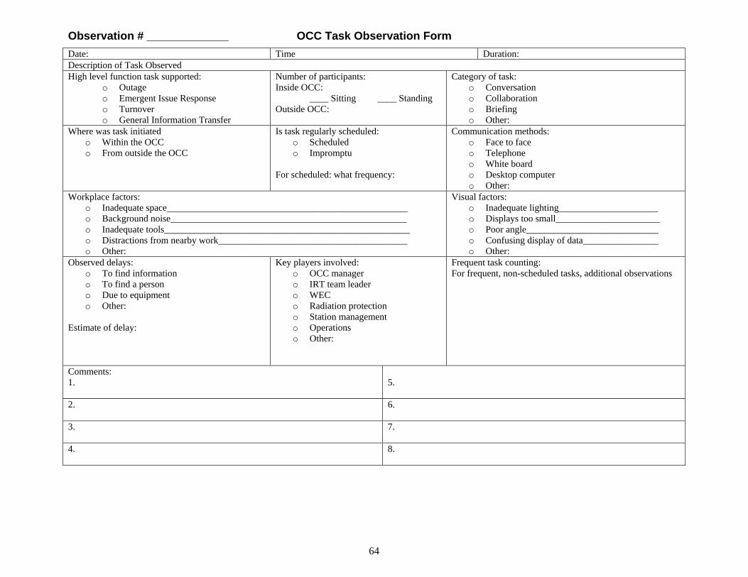
64
Observation # _____________ OCC Task Observation Form Date: Time Duration: Description of Task Observed High level function task supported:
o Outage o Emergent Issue Response o Turnover o General Information Transfer
Number of participants: Inside OCC: ____ Sitting ____ Standing Outside OCC:
Category of task: o Conversation o Collaboration o Briefing o Other:
Where was task initiated o Within the OCC o From outside the OCC
Is task regularly scheduled: o Scheduled o Impromptu
For scheduled: what frequency:
Communication methods: o Face to face o Telephone o White board o Desktop computer o Other:
Workplace factors: o Inadequate space___________________________________________________ o Background noise__________________________________________________ o Inadequate tools____________________________________________________ o Distractions from nearby work________________________________________ o Other:
Visual factors: o Inadequate lighting_____________________ o Displays too small______________________ o Poor angle____________________________ o Confusing display of data________________ o Other:
Observed delays: o To find information o To find a person o Due to equipment o Other:
Estimate of delay:
Key players involved: o OCC manager o IRT team leader o WEC o Radiation protection o Station management o Operations o Other:
Frequent task counting: For frequent, non-scheduled tasks, additional observations
Comments: 1.
5.
2.
6.
3.
7.
4.
8.
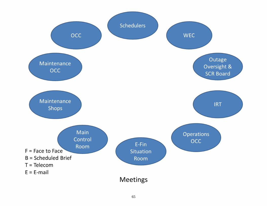
65
Meetings
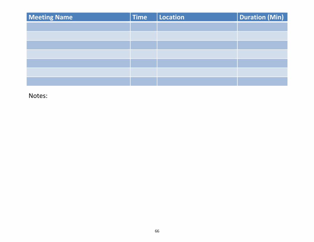
66
Meeting Name Time Location Duration (Min)
Notes:
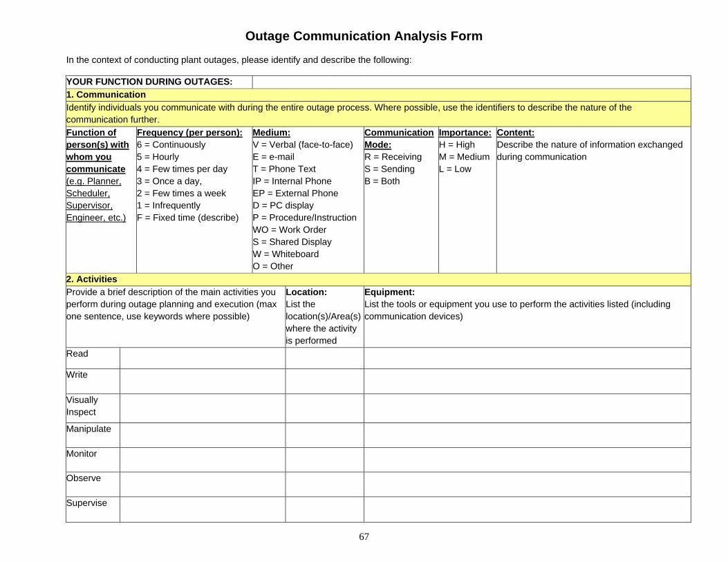
67
Outage Communication Analysis Form
In the context of conducting plant outages, please identify and describe the following: YOUR FUNCTION DURING OUTAGES: 1. Communication Identify individuals you communicate with during the entire outage process. Where possible, use the identifiers to describe the nature of the communication further. Function of person(s) with whom you communicate (e.g. Planner, Scheduler, Supervisor, Engineer, etc.)
Frequency (per person): 6 = Continuously 5 = Hourly 4 = Few times per day 3 = Once a day, 2 = Few times a week 1 = Infrequently F = Fixed time (describe)
Medium: V = Verbal (face-to-face) E = e-mail T = Phone Text IP = Internal Phone EP = External Phone D = PC display P = Procedure/Instruction WO = Work Order S = Shared Display W = Whiteboard O = Other
Communication Mode: R = Receiving S = Sending B = Both
Importance: H = High M = Medium L = Low
Content: Describe the nature of information exchanged during communication
2. Activities Provide a brief description of the main activities you perform during outage planning and execution (max one sentence, use keywords where possible)
Location: List the location(s)/Area(s) where the activity is performed
Equipment: List the tools or equipment you use to perform the activities listed (including communication devices)
Read
Write
Visually Inspect
Manipulate
Monitor
Observe
Supervise
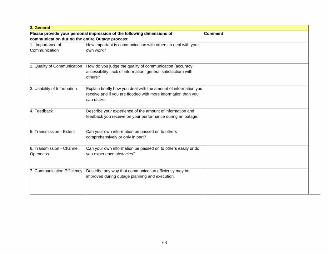
68
3. General Please provide your personal impression of the following dimensions of communication during the entire Outage process:
Comment
1. Importance of Communication
How important is communication with others to deal with your own work?
2. Quality of Communication How do you judge the quality of communication (accuracy, accessibility, lack of information, general satisfaction) with others?
3. Usability of Information Explain briefly how you deal with the amount of information you receive and if you are flooded with more information than you can utilize.
4. Feedback Describe your experience of the amount of information and feedback you receive on your performance during an outage.
5. Transmission - Extent Can your own information be passed on to others comprehensively or only in part?
6. Transmission - Channel Openness
Can your own information be passed on to others easily or do you experience obstacles?
7. Communication Efficiency Describe any way that communication efficiency may be improved during outage planning and execution.
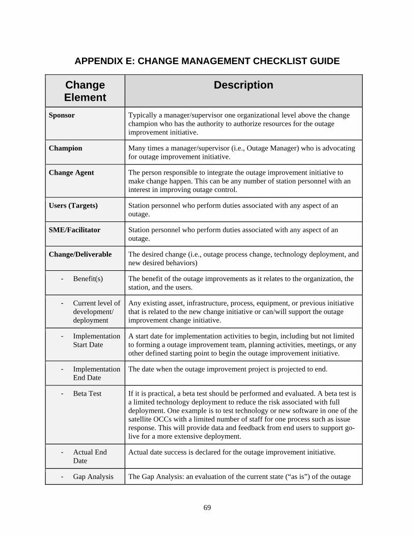
69
APPENDIX E: CHANGE MANAGEMENT CHECKLIST GUIDE
Change Element
Description
Sponsor Typically a manager/supervisor one organizational level above the change champion who has the authority to authorize resources for the outage improvement initiative.
Champion Many times a manager/supervisor (i.e., Outage Manager) who is advocating for outage improvement initiative.
Change Agent The person responsible to integrate the outage improvement initiative to make change happen. This can be any number of station personnel with an interest in improving outage control.
Users (Targets) Station personnel who perform duties associated with any aspect of an outage.
SME/Facilitator Station personnel who perform duties associated with any aspect of an outage.
Change/Deliverable The desired change (i.e., outage process change, technology deployment, and new desired behaviors)
- Benefit(s) The benefit of the outage improvements as it relates to the organization, the station, and the users.
- Current level of development/ deployment
Any existing asset, infrastructure, process, equipment, or previous initiative that is related to the new change initiative or can/will support the outage improvement change initiative.
- Implementation Start Date
A start date for implementation activities to begin, including but not limited to forming a outage improvement team, planning activities, meetings, or any other defined starting point to begin the outage improvement initiative.
- Implementation End Date
The date when the outage improvement project is projected to end.
- Beta Test If it is practical, a beta test should be performed and evaluated. A beta test is a limited technology deployment to reduce the risk associated with full deployment. One example is to test technology or new software in one of the satellite OCCs with a limited number of staff for one process such as issue response. This will provide data and feedback from end users to support go-live for a more extensive deployment.
- Actual End Date
Actual date success is declared for the outage improvement initiative.
- Gap Analysis The Gap Analysis: an evaluation of the current state (“as is”) of the outage
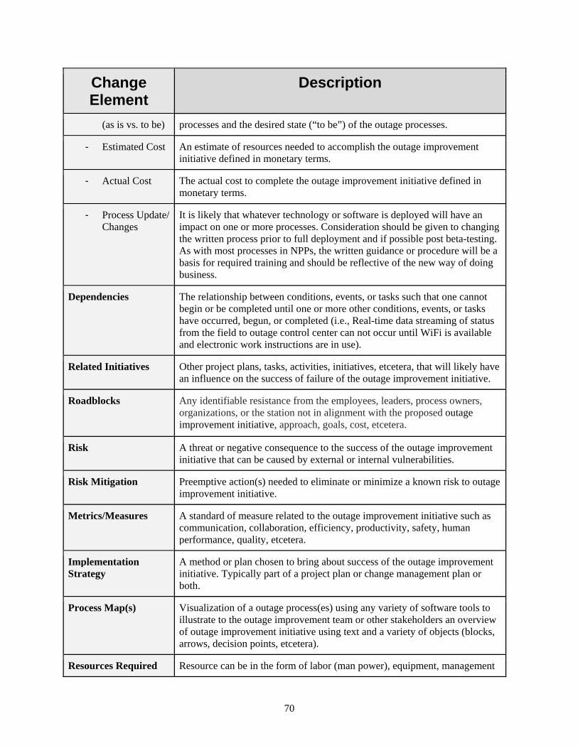
70
Change Element
Description
(as is vs. to be) processes and the desired state (“to be”) of the outage processes.
- Estimated Cost An estimate of resources needed to accomplish the outage improvement initiative defined in monetary terms.
- Actual Cost The actual cost to complete the outage improvement initiative defined in monetary terms.
- Process Update/ Changes
It is likely that whatever technology or software is deployed will have an impact on one or more processes. Consideration should be given to changing the written process prior to full deployment and if possible post beta-testing. As with most processes in NPPs, the written guidance or procedure will be a basis for required training and should be reflective of the new way of doing business.
Dependencies The relationship between conditions, events, or tasks such that one cannot begin or be completed until one or more other conditions, events, or tasks have occurred, begun, or completed (i.e., Real-time data streaming of status from the field to outage control center can not occur until WiFi is available and electronic work instructions are in use).
Related Initiatives Other project plans, tasks, activities, initiatives, etcetera, that will likely have an influence on the success of failure of the outage improvement initiative.
Roadblocks Any identifiable resistance from the employees, leaders, process owners, organizations, or the station not in alignment with the proposed outage improvement initiative, approach, goals, cost, etcetera.
Risk A threat or negative consequence to the success of the outage improvement initiative that can be caused by external or internal vulnerabilities.
Risk Mitigation Preemptive action(s) needed to eliminate or minimize a known risk to outage improvement initiative.
Metrics/Measures A standard of measure related to the outage improvement initiative such as communication, collaboration, efficiency, productivity, safety, human performance, quality, etcetera.
Implementation Strategy
A method or plan chosen to bring about success of the outage improvement initiative. Typically part of a project plan or change management plan or both.
Process Map(s) Visualization of a outage process(es) using any variety of software tools to illustrate to the outage improvement team or other stakeholders an overview of outage improvement initiative using text and a variety of objects (blocks, arrows, decision points, etcetera).
Resources Required Resource can be in the form of labor (man power), equipment, management
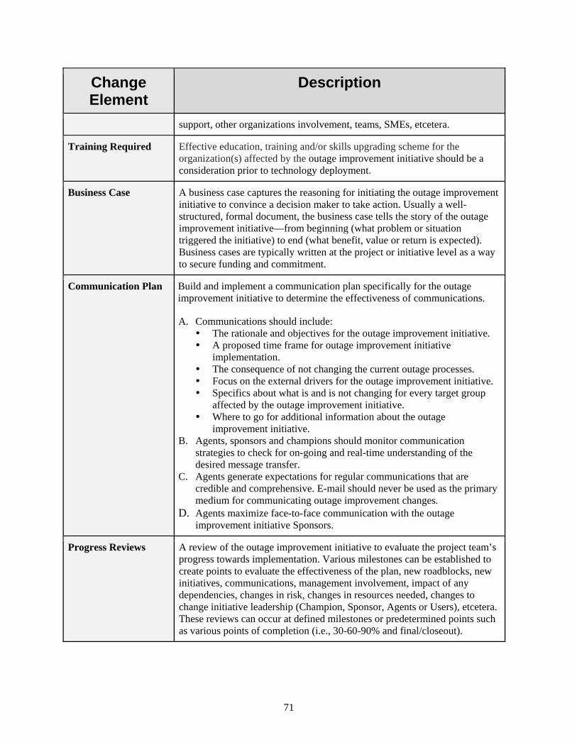
71
Change Element
Description
support, other organizations involvement, teams, SMEs, etcetera.
Training Required Effective education, training and/or skills upgrading scheme for the organization(s) affected by the outage improvement initiative should be a consideration prior to technology deployment.
Business Case A business case captures the reasoning for initiating the outage improvement initiative to convince a decision maker to take action. Usually a well-structured, formal document, the business case tells the story of the outage improvement initiative—from beginning (what problem or situation triggered the initiative) to end (what benefit, value or return is expected). Business cases are typically written at the project or initiative level as a way to secure funding and commitment.
Communication Plan Build and implement a communication plan specifically for the outage improvement initiative to determine the effectiveness of communications.
A. Communications should include: The rationale and objectives for the outage improvement initiative. A proposed time frame for outage improvement initiative
implementation. The consequence of not changing the current outage processes. Focus on the external drivers for the outage improvement initiative. Specifics about what is and is not changing for every target group
affected by the outage improvement initiative. Where to go for additional information about the outage
improvement initiative. B. Agents, sponsors and champions should monitor communication
strategies to check for on-going and real-time understanding of the desired message transfer.
C. Agents generate expectations for regular communications that are credible and comprehensive. E-mail should never be used as the primary medium for communicating outage improvement changes.
D. Agents maximize face-to-face communication with the outage improvement initiative Sponsors.
Progress Reviews A review of the outage improvement initiative to evaluate the project team’s progress towards implementation. Various milestones can be established to create points to evaluate the effectiveness of the plan, new roadblocks, new initiatives, communications, management involvement, impact of any dependencies, changes in risk, changes in resources needed, changes to change initiative leadership (Champion, Sponsor, Agents or Users), etcetera. These reviews can occur at defined milestones or predetermined points such as various points of completion (i.e., 30-60-90% and final/closeout).
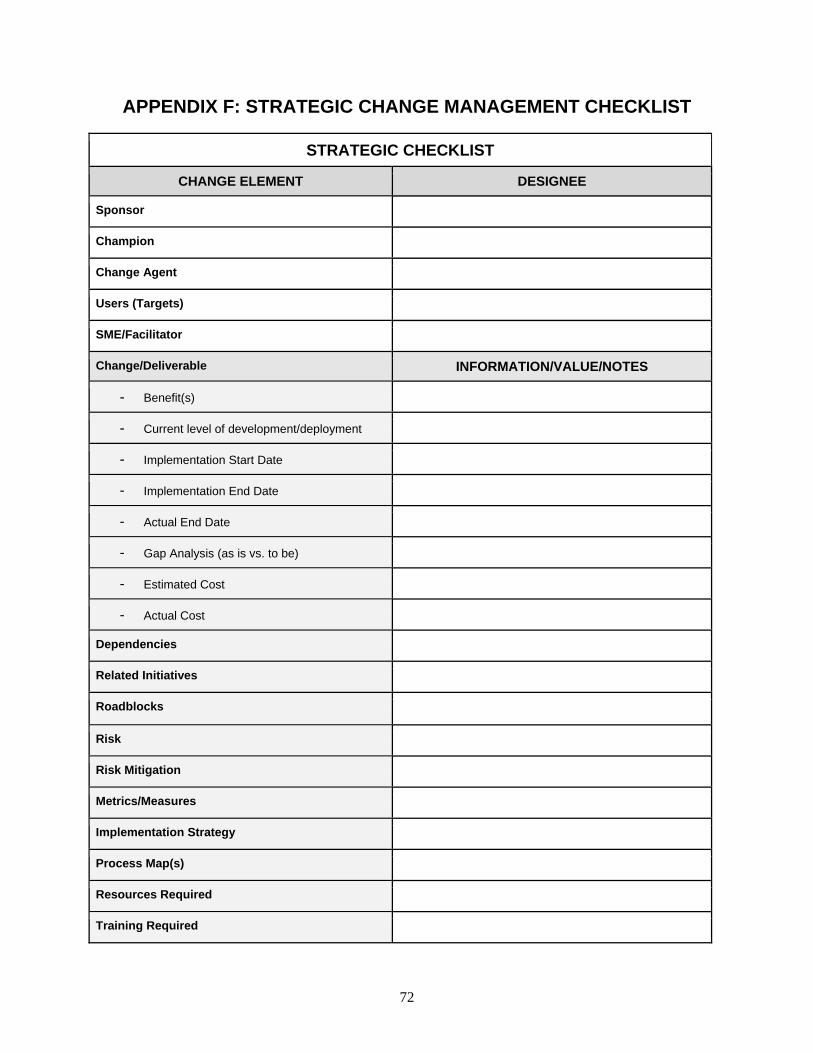
72
APPENDIX F: STRATEGIC CHANGE MANAGEMENT CHECKLIST
STRATEGIC CHECKLIST
CHANGE ELEMENT DESIGNEE
Sponsor
Champion
Change Agent
Users (Targets)
SME/Facilitator
Change/Deliverable INFORMATION/VALUE/NOTES
- Benefit(s)
- Current level of development/deployment
- Implementation Start Date
- Implementation End Date
- Actual End Date
- Gap Analysis (as is vs. to be)
- Estimated Cost
- Actual Cost
Dependencies
Related Initiatives
Roadblocks
Risk
Risk Mitigation
Metrics/Measures
Implementation Strategy
Process Map(s)
Resources Required
Training Required
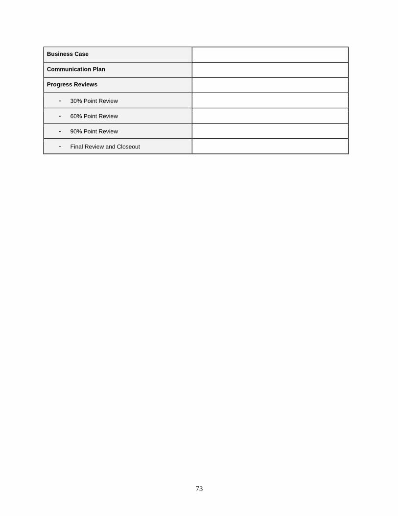
73
Business Case
Communication Plan
Progress Reviews
- 30% Point Review
- 60% Point Review
- 90% Point Review
- Final Review and Closeout
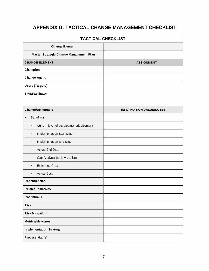
74
APPENDIX G: TACTICAL CHANGE MANAGEMENT CHECKLIST
TACTICAL CHECKLIST
Change Element
Master Strategic Change Management Plan
CHANGE ELEMENT ASSIGNMENT
Champion
Change Agent
Users (Targets)
SME/Facilitator
Change/Deliverable INFORMATION/VALUE/NOTES
Benefit(s)
- Current level of development/deployment
- Implementation Start Date
- Implementation End Date
- Actual End Date
- Gap Analysis (as is vs. to be)
- Estimated Cost
- Actual Cost
Dependencies
Related Initiatives
Roadblocks
Risk
Risk Mitigation
Metrics/Measures
Implementation Strategy
Process Map(s)
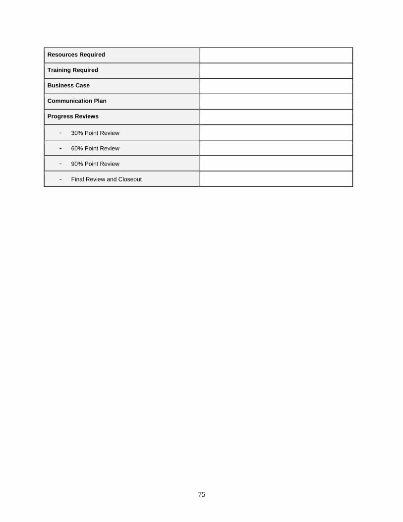
75
Resources Required
Training Required
Business Case
Communication Plan
Progress Reviews
- 30% Point Review
- 60% Point Review
- 90% Point Review
- Final Review and Closeout
76
APPENDIX H: COMMUNICATION PLAN (TEMPLATE)
Communication Plan: One of the key elements of any change is clear and concise communication strategy. In general the three main avenues of communication are: Written:
o Most permanent (most binding, hardest to move away from). o Least expensive. o Communicates to many people quickly. o Provides for great consistency. o Useful to instruct / inform, e.g., guides, manuals. Note: Email should never be used as the primary medium for communicating a proposed change.
Events: o Most dramatic. o Useful to signal a new direction, to begin to get buy-in. o Good for symbolism. o Most carefully attended to by the receiver. o Most labor intensive, often most expensive.
One-on-one: o Most effective for persuasion.
Communications should include: The rationale (why) and objectives for the proposed change. A proposed time frame for change implementation. The cost (consequence) of not changing. Focus on the external drivers for the change. Specifics about what is and is not changing for every target group. Where to go for additional information.
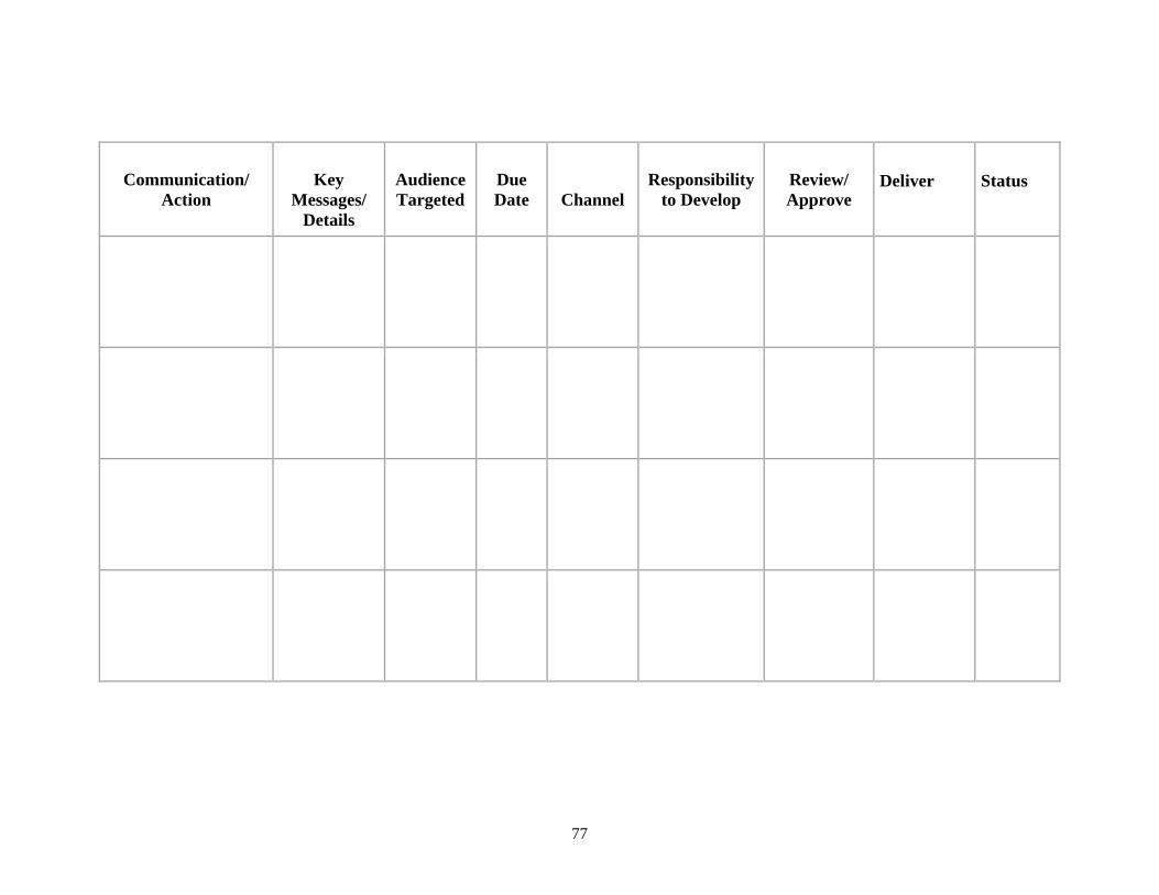
77
Communication/
Action
Key
Messages/ Details
Audience Targeted
Due Date
Channel
Responsibility
to Develop
Review/ Approve
Deliver
Status