Guidelines for Impact Moling - Louisiana Tech TTC...
25
Guidelines for Impact Moling TTC Technical Report #2001.03 Jadranka Simicevic Raymond L. Sterling Prepared for: U.S. Army Corps of Engineers Engineering Research and Development Center (ERDC) 3909 Halls Ferry Road Vicksburg, MS 39180 March 2001
Transcript of Guidelines for Impact Moling - Louisiana Tech TTC...

Guidelines for
Impact Moling
TTC Technical Report #2001.03
Jadranka Simicevic
Raymond L. Sterling
Prepared for:
U.S. Army Corps of Engineers
Engineering Research and Development Center (ERDC)
3909 Halls Ferry Road
Vicksburg, MS 39180
March 2001

i
DISCLAIMER
This report was prepared by the Trenchless Technology Center (TTC) for the U.S. Army Corps of Engineers, Engineering Research and Development Center (ERDC). Neither TTC, the U.S. Army Corps of Engineers, nor any person acting on their behalf, makes a warranty, express or implied, with respect to the use of any information, apparatus, method, or process disclosed in this report or that such use may not infringe on privately owned rights; or assumes any liabilities with respect to the use of, or for damages resulting from the use of, any information, apparatus, method, or process disclosed in this report.

ii
TABLE OF CONTENTS Preface ..................................................................................................................................................iv
Executive Summary...............................................................................................................................v
1 Introduction ...................................................................................................................................1 1.1 Method Description......................................................................................................................1 1.2 Range of Applications ..................................................................................................................3 1.3 Market for Impact Moling ............................................................................................................3
2 Applicable References....................................................................................................................4 2.1 Standards .....................................................................................................................................4 2.2 Reports ........................................................................................................................................5
3 Design Considerations ...................................................................................................................6 3.1 Borehole Layout...........................................................................................................................6 3.2 Depth ...........................................................................................................................................6 3.3 Mole Type ...................................................................................................................................6 3.4 Non-Steerable Moles....................................................................................................................7 3.5 Steerable Moles............................................................................................................................8 3.6 Tool Size......................................................................................................................................8 3.7 Air Supply ...................................................................................................................................8 3.8 Protective Sleeves ........................................................................................................................9 3.9 Distance from Nearby Utilities .....................................................................................................9
4 Construction Considerations .......................................................................................................11 4.1 Excavations................................................................................................................................11 4.2 Tool Alignment and Launching ..................................................................................................12 4.3 Boring with Non-Steerable Moles ..............................................................................................12 4.4 Boring with Steerable Moles ......................................................................................................13 4.5 Boring Speed .............................................................................................................................14 4.6 Tool Lubrication ........................................................................................................................14 4.7 Effect of Outside Air Temperature .............................................................................................14 4.8 Product Pipe Installation.............................................................................................................14
5 Bid Documents .............................................................................................................................15
References ............................................................................................................................................16
APPENDICES .....................................................................................................................................17 Appendix A: Moving Heads – Latest Designs ..................................................................................17 Appendix B: Steerable Moles - Prototypes.......................................................................................18 Appendix C: “Lost Tool” Retrieval..................................................................................................19

iii
LIST OF FIGURES Figure 1: Two-stage moving head action..................................................................................................2
Figure 2: The schematic of impact moling................................................................................................2
Figure 3: Reciprocating stepped-cone head (TT Technologies).................................................................7
Figure 4: Steerable mole (TT Technologies) ............................................................................................8
Figure 5: Excavations in impact moling .................................................................................................11
Figure 6: Insertion pit ............................................................................................................................11
Figure 7: Tool alignment........................................................................................................................12
Figure 8: Two-stage moving head action without pre-tensioned steel spring (Vermeer) ..........................17
Figure 9: Steerable mole with dual-position steering head (Foster-Miller) ..............................................18

iv
Preface Although impact moling is an established and widely used trenchless method for installation of smaller pipes over shorter lengths, it has not been not covered adequately with guidelines and standards. The need for guidelines in this area was demonstrated in a study Identification of Needs for User Guidance in Trenchless Technology Applications, which was prepared by the Waterways Experiment Station (WES) (now Engineering Research and Development Center - ERDC) with the assistance of the Trenchless Technology Center (TTC) in 1998. The study surveyed existing guidelines and standards, as well as those under development by various organizations in the USA and abroad, and identified pipe bursting, pipe ramming and impact moling as areas of trenchless technology with priority needs for guidance development.
These guidelines are based on information obtained from manufacturers' literature, technical papers, and other related information, and from comments and reviews made by industry experts. The following industry representatives are especially thanked for their reviews and advice:
§ Mr. Steve Sabo, Allied Construction Products, Inc
§ Dr. Gerald A. Stangl, The Charles Machines Works, Inc.
§ Dr. Floyd Gunsaulis, Ditch Witch/Charles Machine Works
§ Mr. Don Hudak, Hudco Manufacturing, Inc.
§ Mr. Brian A. Mattson, TT Technologies, Inc.
§ Mr. Herbert K. Quigley, Vermeer/ Earth Tool Co.

v
Executive Summary These guidelines have been prepared to assist owners, designers and contractors involved in new pipe installation projects to evaluate capabilities of impact moling for such projects and to design and carry out impact moling jobs effectively and safely, in consistence with project requirements and site conditions. The objective of the guidelines is to give a clear understanding of the method, outline important design and construction considerations, identify potential problems and prevention measures and thus to engender confidence in the use of the method.
Impact moling is a trenchless method for installation of pipes up to 10-inches in diameter over distances up to 200 ft. It is the most widely used trenchless installation method and has applications in installation of gas and water lines, cabling etc. The method uses a compaction principle to create a bore and thus is the most appropriate for compressible soils. Difficulty can arise with densely packed soils due to the difficulty in compaction and with loose sands and gravels due to collapse of the borehole. In order to ensure successful completion of an impact moling job, it is essential to know the ground conditions and to identify the depth and location of all existing utilities and other underground objects nearby.
Most impact moles are non-steerable and most bores are planned as straight bores. Non-steerable moles can be designed with fixed or moving heads. Various head designs are available for moles including replaceable heads to adjust to the ground conditions. Non-steerable moles must be carefully aligned in the insertion pit because a correct starting alignment is one of the essential conditions for an accurate bore. Once in the ground, non-steerable moles are intended to advance in a straight line and the operator can control the maintenance of alignment only through the tool’s air supply. Non-steerable moles can also be provided with a tracking feature. If the bore deviates too much from the intended alignment, the tool is reversed and backed out of the hole and the bore restarted.
In recent years, steerable systems have reached the market allowing curved trajectories and bores with multiple direction changes, as well as alignment corrections during the moling process, if needed. These moles are currently commercially available in only one size and, being still fairly new to the marketplace, are still waiting for wide acceptance.
Impact moling should be carried out at a depth of at least 10 times the diameter of the product pipe or 3-4 ft, whichever is greater, to avoid surface damage. The speed of moling can affect accuracy of the bore, and the advance rate is on average about 1-5 ft/min for non-steerable moling, and about 1 ft/min for steerable moling.
The product pipe is usually installed after the bore is completed, but can also be pulled into place while the bore is being moled. This is advantageous in loose soils where the unsupported borehole can cave in. If the product pipe is small or should not be contaminated by the lubricating oil in the exhaust, a sleeve pipe should be used.
Impact moling jobs generally don’t involve bidding on individual jobs because municipal agencies either have their own crews equipped with impact moles or engage contractors on general contracts. Therefore these guidelines incorporate bid criteria for the purchase of an impact mole instead of guidelines for individual impact moling projects.
1
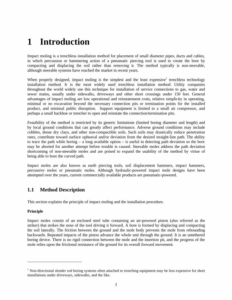
1 Introduction Impact moling is a trenchless installation method for placement of small diameter pipes, ducts and cables, in which percussion or hammering action of a pneumatic piercing tool is used to create the bore by compacting and displacing the soil rather than removing it. The method typically is non-steerable, although steerable systems have reached the market in recent years.
When properly designed, impact moling is the simplest and the least expensive1 trenchless technology installation method. It is the most widely used trenchless installation method: Utility companies throughout the world widely use this technique for installation of service connections to gas, water and sewer mains, usually under sidewalks, driveways and other short crossings under 150 feet. General advantages of impact moling are low operational and reinstatement costs, relative simplicity in operating, minimal or no excavation beyond the necessary connection pits or termination points for the installed product, and minimal public disruption. Support equipment is limited to a small air compressor, and perhaps a small backhoe or trencher to open and reinstate the connection/termination pits.
Feasibility of the method is restricted by its generic limitations (limited boring diameter and length) and by local ground conditions that can greatly affect performance. Adverse ground conditions may include cobbles, dense dry clays, and other non-compactible soils. Such soils may drastically reduce penetration rates, contribute toward surface upheaval and/or deviation from the desired straight-line path. The ability to trace the path while boring – a long available option – is useful in detecting path deviation so the bore may be aborted for another attempt before trouble is caused. Steerable moles address the path deviation shortcoming of non-steerable moles and are poised to expand the usability of the method by virtue of being able to bore the curved path.
Impact moles are also known as earth piercing tools, soil displacement hammers, impact hammers, percussive moles or pneumatic moles. Although hydraulic-powered impact mole designs have been attempted over the years, current commercially available products are pneumatic-powered.
1.1 Method Description
This section explains the principle of impact moling and the installation procedure.
Principle
Impact moles consist of an enclosed steel tube containing an air-powered piston (also referred as the striker) that strikes the nose of the tool driving it forward. A bore is formed by displacing and compacting the soil laterally. The friction between the ground and the mole body prevents the mole from rebounding backwards. Repeated impacts of the piston advance the whole unit through the ground. It is an untethered boring device. There is no rigid connection between the mole and the insertion pit, and the progress of the mole relies upon the frictional resistance of the ground for its overall forward movement.
1 Non-directional slender rod boring systems often attached to trenching equipment may be less expensive for short installations under driveways, sidewalks, and the like.

2
The hammering action can either be a simple striking of the piston onto the forward end of the unit or a two-stage action of a specially designed moving head. Figure 1 shows the two-stage action. Compressed air repeatedly propels the piston against the rear of the chisel head assembly. This first compresses the pre-tensioned steel spring2, which forces the chisel head assembly forward independently of the main casing. The first impact creates a pilot bore. Then, the same continuous force thrusts the main casing ahead. The second impact expands the borehole to its final diameter.
Figure 1: Two-stage moving head action
Installation Procedure
Non-steerable moles typically involve the excavation of two pits: an insertion pit and a receiving pit. After the careful alignment of the mole in the insertion pit, the tool is expected to advance through the ground in a straight line. A single person can operate the mole.
Steerable moles may be launched from the surface or from a pit. The operation requires a two-man crew. A walkover tracking system is used, as in directional drilling industry, where one operator walks the bore route with a walkover locator device and monitors the progress of the tool in the ground. The other operator is a tool operator who implements the required course corrections using the guidance controls.
Figure 2: The schematic of impact moling
A product pipe, cable or cable duct can either be directly towed into the bore during the boring procedure or subsequently inserted into place after the borehole is completed (providing suitable soil conditions for unsupported borehole). Usually the mole first creates the unsupported bore, and upon removing the unit
2 The latest advancement in the active head design eliminates the need for the spring. See Appendix.
Line of Vision
Compressor
Starting Pit
Impact MoleCasing
Target Pit
Air Hose
Terrain Top

3
from the receiving pit, the product pipe is attached to the air hose and pulled into the bore (the most popular mode of operation), or the pipe is sometimes pushed into its place.
Impact moling can also be used for dead-end bores, in which case the tool is reversed after the bore is completed and removed from the ground through the insertion pit.
1.2 Range of Applications
Impact moling can be used for installation of pipes up to 10 inches in diameter, but typically is used for pipes in the diameter range between ½ and 4 inches. Installed pipes are usually made of PVC, HDPE or steel. Depending on tool size and soil conditions, the maximum boring distance for non-steerable moling is between 10-100 ft, or even longer, but the typical installation length is usually up to 35 ft in one run. Steerable systems allow moling to be carried out in longer runs, up to 200 ft in good soil conditions. However, penetration rates of moles in comparison to other techniques such as directional drilling should be taken into account when longer bores are being considered.
The method has a wide range of applications. Besides gas and water service lines, these tools are used for cabling, cable ducts, garden irrigation, water treatment systems, outside water supplies, landscape lighting, drain replacements, lead piping replacement, etc. Impact moles can also be used for other applications, for example in pipeline rehabilitation for pulling a liner into the pipe or in non-utility applications for the installation of environmental wells.
Because the method uses a compaction principle to create the bore, this technique is appropriate for compressible soils. Ground conditions suitable for impact moling include clays, silt, peat and generally soft cohesive material. Sands and gravel are considered less appropriate, especially if they are densely packed, while solid rock is entirely unsuitable for this technique.
1.3 Market for Impact Moling
Impact moles are the most widely used trenchless construction equipment. Tens of thousands are in service with utilities and contractors worldwide (Flaxman 1999).
Both the gas and the water industry have a large demand for new service lines installation. More than 1.2 million polyethylene gas services are installed annually in the United States, of which about 800,000 are new installations and 400,000 are replacements (Fisk et al 1995). The average service length is 70 ft, about 95% of them are under 4 inches in diameter, and 72% are under 2 inches in diameter. In addition, about 17,000 miles of polyethylene gas mains are installed each year, of which 95% are up to 4 inches in diameter and 72% up to 2 inches in diameter. Open-cut methods are used for installation of about 95% of new gas services and for more than 66% of new gas mains. The water industry has a similar demand for small pipe installation.
In favorable soil conditions, impact moling might be the best-suited trenchless method to address these segments of gas and water industry, because even the smallest mini-directional drills are larger and more costly than impact moles. However, additional factors such as potential for surface upheaval and overall job productivity should be taken into consideration when selecting impact moling over other installation methods. One must also remember to factor in costs associated with the air compressor required to operate a mole. Still, compared to other trenchless methods on smaller jobs, and especially to open cut and resurfacing, impact moling can obtain substantial cost and time savings. On some projects time saving can be measured in hours and even in days.

4
2 Applicable References
2.1 Standards
The process of impact moling is not covered by any standards yet. The only related standards developed so far cover the pipes to be installed.
§ American Society for Testing Materials (ASTM)
ASTM D 638-99 Test Method for Tensile Properties of Plastics
ASTM D 1248-00 Standard Specification for Polyethylene Plastics Extrusion Materials For Wire and Cable
ASTM D 1599-99 Standard Test Method for Resistance to Short-Time Hydraulic Failure Pressure of Plastic Pipe, Tubing, and Fittings
ASTM D 1784-99a
Standard Specification for Rigid Poly(Vinyl Chloride) (PVC) Compounds and Chlorinated Poly(Vinyl Chloride) (CPVC) Compounds
ASTM D 2104-99e1 Standard Specification for Polyethylene (PE) Plastic Pipe, Schedule 40
ASTM D 3034-00 Standard Specification for Type PSM Poly(Vinyl Chloride) (PVC) Sewer Pipe and Fittings
ASTM D 3212-96a Standard Specification for Joints for Drain and Sewer Plastic Pipes Using Flexible Elastomeric Seals
ASTM D3261-97 Standard Specification for Butt Heat Fusion Polyethylene (PE) Plastic Fittings for Polyethylene (PE) Plastic Pipe and Tubing
ASTM D 3350-99 Standard Specification for Polyethylene Plastics Pipe and Fittings Materials
ASTM F 477-99 Standard Specification for Elastomeric Seals (Gaskets) for Joining Plastic Pipe
ASTM F 714-97 Standard Specification for Polyethylene (PE) Plastic Pipe (SDR-PR) Based on Outside Diameter
§ American National Standard Association (ANSI)/National Sanitation Foundation (NSF)
ANSI/NSF Standard 14-1999 Plastics Piping System Components and Related Materials

5
2.2 Reports
_, 1999. Use of Trenchless Techniques for the Construction of Underground Infrastructures for Telecommunication Cable Installation, [L.38] Recommendation L.38 International Telecommunication Union (ITU), September 1999, Geneva, Switzerland.
_, 1999. Horizontal Directional Drilling and Impact Moling, IGE/SR26, IgasE Communication 1662, The Institution of Gas Engineers (IgasE), 53p, London, UK.
_, 1999. Horizontal Directional Drilling and Impact Moling: Operators Guide, Safety Recommendations IGE/SR26A, Communication 1664, The Institution of Gas Engineers (IgasE), October 1999, 19p, London, UK.
_, 1998. Trenchless Technology Guidelines, International Society for Trenchless Technology (ISTT), 52p, London, U.K.

6
3 Design Considerations
3.1 Borehole Layout
When designing the borehole layout, consideration needs to be given to project requirements, equipment capabilities, and ground conditions. Although most ground conditions can be moled, they are not equally suitable for moling: the best soil type is moderately compacted soil with moderate moisture content that stays unchanging along the desired borehole route. Difficulty arises with loose soil, wet sand and solid rock, and changing ground conditions: changes in strata both natural and artificial3 should be identified. All underground objects on the job site must be located and known, i.e., depth and exact position of sewer and water mains and other utility lines, and any other facility to be crossed. Consideration should also be given to the possible existence of tree roots, as they normally obstruct moling operations. In the design phase, the existing ground conditions may affect selection of borehole route, mole type and mole head design.
Most bores done with impact moles are planned as straight bores. However, steerable moles make possible curved trajectories, as well as bores with multiple direction changes, both horizontal and vertical. Even severe direction changes such as 30-degree turns can be accommodated. The steering radius of curved trajectories depends on soil conditions, but should be at least 85 ft.
3.2 Depth
The working depth should be at least 10 times the tool diameter or 3-4 ft, whichever is larger, to avoid surface damage from soil displacements. This minimum ground cover provides sufficient overburden to ensure directional stability of the hole. If the hole is too shallow, the mole can have the tendency to rise toward the surface. Thus, other types of installation methods should be considered when shallower product installation is desired.
3.3 Mole Type
In general, non-steerable moles are intended for straight bores and steerable moles are intended for inclined or curved bores. Sometimes, however, steerable moles should be considered for straight bores as well. For example, in certain ground conditions – such as stony or layered soils - steering corrections may be needed to follow the designed straight path. Non-steerable moles have difficulty keeping on course in changing ground conditions. They are, in general, capable of displacing minor obstructions in the ground without deviation, but hard inclusions can throw them off course. Therefore, in stable (unchanging) ground conditions, if no obstructions can be foreseen, and especially if the distance to be crossed is short,
3 Buried utilities are often backfilled with stone, gravel, sand or other combination of backfill material, and such trenches are potential problem areas for moling operations.

7
the non-steerable mole is safe to use. Otherwise, when a steering correction is likely to be called for, the steerable mole should be selected. The limitation here is the fact that the steerable moles are currently available in only one size. It should also be acknowledged that, at this time, steerable moles are still fairly new to the marketplace and not in common use. They provide a significant advance in moling technology, but are still proving functionality and reliability in use in order to gain wider acceptance.
3.4 Non-Steerable Moles
Replaceable Heads
Non-steerable moles can be provided with replaceable heads, which make them adaptable for different soil conditions. Several tool heads have been developed for different soil conditions to be used on moles with replaceable heads. Good selection of the tool head can improve the directional stability of the mole. Tapered heads are used in loose and wet soils when no buried obstacles are expected. Splined and stepped heads are better for dry, highly compact soils that may include obstacles. Stepped heads are suitable for soils known to include rocks and other obstacles.
Trackable Moles
Non-steerable moles may optionally incorporate a tracking feature by which the depth and location of the mole can be tracked with a walkover receiver. For this purpose a sonde (also known as a beacon or probe) is placed in a special housing between the “hose whip” (short hose) at the back of the tool and the air supply hose, or in a special housing at the nose of the mole. This allows the operator to determine if the unit is on the correct line. If necessary the bore can be corrected by backing up the mole and restarting or by controlling the speed of moling, which is done by lowering the pressure or volume of air supply provided by the air compressor.
Fixed Heads vs. Moving Heads
Non-steerable moles can be designed with fixed or moving heads. Moles with fixed heads have fewer moving parts, which makes them easier to maintain than moving head moles. Proponents of moving head moles claim these are more capable of handling adverse soil conditions than fixed head moles. However, either type may take the line of least resistance when encountering intrusions in the bore path and might be deviated in such ground conditions.
Moles with moving heads use a two-stage action described earlier in chapter 1.1. Figure 3 shows one type of mole with a moving head. The chisel tip tends to jackhammer and destroy obstacles in its path, and the stepped-cone body is designed for compacting and displacing the soil laterally.
Figure 3: Reciprocating stepped-cone head (TT Technologies)

8
3.5 Steerable Moles
Over the years a number of attempts have been made to develop a steerable mole, and some early prototypes are described in Appendix A. Presently only one type is being offered on the market. It uses walkover tracking and remote steering similar to that used in the horizontal directional drilling industry. A sonde integrated within the forward end of the tool body is ruggedized to withstand the hammering impact of the mole. The head of the mole is immovable and as such has a continuous tendency to steer. In order to bore approximately straight the mole has to be rotated as it advances, and as a result a zigzag path is created when boring a nominally straight path.
Figure 4: Steerable mole (TT Technologies)
3.6 Tool Size
The diameter of the mole is determined by the pipe outer diameter: the created hole should be approximately 15-25% larger diameter than the product pipe to allow for borehole shrinkage and to reduce the friction between the pipe and the soil. If the installed product pipe comes with bell joints, the hole should be further enlarged and the manufacturers’ recommendations for the tool size should be followed.
Some non-steerable moles can operate in conjunction with expanders that enable widening of the bore to diameters larger than the mole itself. The non-steerable moles are available in various sizes, typically from 1¾ to 8 inches, creating boreholes from 1¾ to 10 inches. Steerable moles are currently available only in one diameter size (3 inches). The feasibility and market need for other sizes (1½ and 5 inches) are being evaluated.
Length of the mole can be an issue in very confined places. Moles typically vary in length from 35 to 130 inches. Depending on the size and brand, the non-steerable moles typically weigh between 20 and 500 pounds, and some large models even more. The number of cycles per minute is typically between 200 and 400, but can be much higher (in some models over 700). The steerable mole is 87 inches long and weighs 85 pounds.
3.7 Air Supply
Most impact moles operate from a standard air compressor and, for their optimal operation, a compressor of adequate capacity is required. The air consumption for impact moles depends on the size and type of the mole, but is typically in the range between 20 – 200 cfm. Operating pressure at the point where air

9
hose is connected to the mole should not exceed the value recommended by the manufacturer and, as a rule of a thumb, there is a 2 psi drop in air pressure per 100 ft of the air hose4.
The air hose should be lightweight, flexible, and collapse resistant. For steerable moling, it should also have high torsional stiffness.
3.8 Protective Sleeves
A protective sleeve is an auxiliary pipe, usually made of polyethylene (PE), which is attached to the rear of the mole and pulled in place while the borehole is being created. The product pipe is subsequently inserted into the sleeve, and the sleeve is then either left in the soil or pulled out of the ground.
Most moling jobs are successfully completed without protective sleeves, but in some situations they should be considered. In unstable soils (sand, loose gravel, etc) the unsupported borehole can easily cave in blocking the exhaust ports of the tool. If this happens, the tool cannot function properly: the mole can lose its bite and completely stop. The purpose of the sleeve is to allow the tool’s air ports to stay free – it allows the airflow from the mole air ports to flow out of the borehole. The alternative is to pull the product pipe in place while moling, but a potential drawback is possible contamination of the product pipe by lubricating oil in the exhaust. A sleeve should also be considered when the product pipe is too small to be used for this purpose.
3.9 Distance from Nearby Utilities
Any project performed in the proximity of another utility line or any other underground object carries a potential risk of damaging it. In impact moling, the biggest risk comes from possible deviation of the mole from the designed path. Another risk is the potential for possible damage caused by vibrations from the pneumatic hammering action. Some pipes, such as asbestos cement pipes, can be very sensitive to the sudden dynamic loading introduced with impact moling.
The risk of hitting the existing services is considered the most important shortcoming of non-steerable moles because they are difficult to keep on course when soil conditions are even mildly changing. On the other hand, their accuracy can be quite high in stable ground conditions where, with proper initial alignment, the accuracy is expected to be within 1%, both in line and grade.
The accuracy of steerable moles depends on the accuracy of tracking system in the mole and the skill of the operator. The stated accuracy of the tracking system is usually 2-5 % of the depth, and because the cover depth in impact moling is typically 3-4 ft, it is expected that the accuracy would be within 1-3 inches from designed bore path. This makes them applicable in closer proximity to existing utilities and the empirical recommendation for the minimum distance from adjacent utilities is 1-2 ft. If impact moling is to be carried very close to existing utilities, it is recommended that the existing utility be exposed at the crossing point so that the clearance of the moling head can be visually confirmed.
Vibration levels due to impact moling depend on the impact applied during the boring process and therefore on the mole’s diameter and number of cycles per minute, and the soil properties. The soil-pipe
4 Pressure loss varies depending on the diameter of the air hose. Stated drop of 2 psi per 100 ft is expected for 1¼-inch air hose.

10
interaction during impact moling is similar to the soil-pipe interaction during pipe bursting. It is not likely that pipe bursting would damage the nearby utilities as long as they are at a distance of at least twice the replacement pipe diameter (Atalah, 1998). However, compared to pneumatic pipe bursting, impact moling may create larger dynamic effects and volume changes within the soil. Impact moles can operate at higher number of cycles per minute and they have to compact more soil than pipe bursting (the full volume of the installed pipe for moling vs. the volume of upsizing only for pipe bursting). On the other hand, impact moling is mostly carried out in soft, easily compressible soils that do not transfer loads as readily as hard soils. Currently there is only limited research about the soil-pipe interaction during impact moling (Chapman at al, 1998), and the research is still insufficient to indicate safe distances between impact moling operation and existing services. The empirical recommendation is six times the diameter of the pipe being installed.

11
4 Construction Considerations
4.1 Excavations
Excavation of insertion and receiving pits is required for non-steerable moles. Although steerable moles can be surface launched, they are often launched from pits as well to facilitate in-line connections among pipe sections. When service connections need to be made, potholes exposing these services should be dug and used as connection pits.
Figure 5: Excavations in impact moling
Excavations depend on the size of the mole, and are typically 4-6 ft long. The pit has to be wide enough to accommodate an operator for tool alignment and bore initiation, and in most cases a backhoe bucket width (18-24 in) is sufficient. Depth of pits depends on the size of the pipe to be installed, and the thickness of the ground cover above the pipe. The pits should be back sloped or shored to conform to local and national safety work codes.
Figure 6: Insertion pit
Longer pipe lengths are usually installed as a series of shorter runs with pits dug at 30-35 ft intervals, and a technique termed “stitch boring” can be applied to increase productivity. In this technique, a series of
Length 4-6 ft
Width 3-6 ft

12
pits is excavated first and the mole is run continuously through them with the air line and any sleeve pipe extending from the start pit to the end pit. The product pipe is then pulled in place and the pits backfilled. The intervening pits allow alignment correction but the friction drag on the air line or sleeve pipe depends on the total length of the run.
4.2 Tool Alignment and Launching
Correct alignment of the tool in the insertion pit is extremely important for any impact moling project, but especially for non-steerable moling where bore accuracy cannot be achieved without the correct starting alignment. Specially designed aim and launch equipment can assure that the mole is aligned both vertically and horizontally before the boring starts. Such equipment includes an aiming frame, a surveyor’s stake, a starting cradle and anchor stakes. Smaller moles are usually hand-launched, while larger moles may need a starting cradle for launching.
Small diameter moles are usually laid on the bottom of the pit and pointed at the receiving pit. Once the tool is aligned, it should be run into the ground with reduced power until it is one third into the ground. Then the launching should be stopped and the alignment checked, and if necessary corrected. Until the mole is completely in the ground, it may be necessary to check and correct the line and grade several times.
Larger moles should use a starting cradle for exact alignment of grade and direction. First the cradle is lowered into the pit and the mole centered on the cradle. The anchor stakes are driven into place to fix the cradle to the pit floor, and the cradle adjusted both vertically and horizontally with the adjusting screws. Launching with stops for checking and correcting the alignment should be done as for smaller moles.
Figure 7: Tool alignment
If the tool is shaking or rapidly cycling back and forth in the insertion pit, the mole is said to be “swimming” in the bore. In such cases, the air supply should be reduced to allow the soil to grip the sides of tool and allow the mole to move forward.
4.3 Boring with Non-Steerable Moles
After the mole is launched, the tool is expected to advance through the ground in a straight line. The operator has little control over the actual path of the mole once launched. The operator sometimes reduces the blow energy and cycle rate of the piston by feathering the air supply to try to maintain better alignment. Monitoring progress with tracking equipment (optional) allows the operator to reverse the tool
Bore Axis
Line of Vision
Working Depth

13
if it begins to veer off course. However, backing the tool out and restarting the bore is time consuming and reduces productivity significantly.
Reversing the tool can be accomplished in different ways depending on the mole design. Some moles require multiple rotations of the hose to switch between forward and reverse operation, others only a portion of a hose rotation, while still others are reversed by controlling the air pressure in an auxiliary air line. How the moles are reversed can affect the success of being able to back the tools up if there are problems with the bore.
Besides veering off course, impact moles can encounter other problems. If the mole unexpectedly hits a change of soil type from hard to soft it can stop moving forward while just pounding in place (“swimming”). The tool usually makes a different sound when this happens, and it is recommended to listen carefully for a change of sound during moling. The problem can usually be corrected by reducing the air supply and pushing on the product pipe (if it is attached to the mole). Otherwise, the tool can be backed out by pulling on the air hose. Another problem is a “lost tool” which can happen when the hole caves in behind the tool. Pulling on the air hose may only stretch the hose instead of reversing the tool. A possible solution to retrieving the “lost tool” is described in Appendix C.
4.4 Boring with Steerable Moles
Boring with steerable moles requires a two-person crew: the tracker operator and the mole operator. The information provided to them by the tracking system is the tool head position, depth, pitch, and roll. (Pitch is the inclination of the mole expressed in percentage of slope. Roll is the rotational position of the mole nose, commonly referred to as a “clock face”. The 12-hour clock configuration is the basis for steering: up is 12 o-clock, down is 6, left is 9 and right is 3.)
Tracker Operator
The tracker operator walks over the bore with a walkover receiver and determines the position of the tool as it advances in the ground. It is recommended that he/she mark the bore path on the ground with flags or spray paint. The most important task for the tracker operator is to detect horizontal deviation from the planned bore and to communicate this information to the operator of the mole. Although he/she can monitor vertical deviation as well, it is usually easier for mole operator to detect the need for the pitch correction.
Mole Operator
The mole operator at the launch point has the control unit with continuous display of pitch and roll. The resolution of the pitch sensor is much better than the resolution of depth measurement available to the tracker, so the operator is the one to detect the need for the pitch correction and immediately corrects it. The operator does all the steering according to the planned route.
Because moles have a fixed angle of slanted face they are continuously steered in the direction of the slanted nose. When boring straight, the operator usually rotates the mole body 180-degrees (moving the nose position from 12-oclock to 6-oclock) every 15 ft or so, creating a zigzag path. To make the rotation he applies the torque to the air hose from the surface. When changing the borepath direction, the operator simply adjusts the roll in desired direction, producing either horizontal or vertical deviation. The rotation of the mole body, which is required during steering, is often difficult because of the friction between the mole and the soil, and a friction sleeve inside which the mole body rotates is recommended. Such a sleeve can reduce the overall friction by up to 90%.

14
4.5 Boring Speed
Penetration rate of a mole depends on soil conditions and can vary considerably in just one crossing. Speed can affect the accuracy of boring if it is too high. The average penetration rate for non steerable moling is about 1-5 ft/min. The penetration rate may be further increased if the required bore accuracy is not high and can reach 8-10 ft/min or more in good soil conditions5. This usually involves use of some special attachments to the body of the mole. In moist clays, the speed can be increased by slipping a steel sleeve on the mole body just behind the head to produce a slightly bigger overcut and thus reduce the overall soil/tool friction. In sandy soils, it can be increased by substituting the stepped head with a smooth coned head. The average speed for steerable moling is 1 ft/min.
4.6 Tool Lubrication
The moles normally require continuous lubrication for their optimal performance. The in-line lubricator, which is located between the compressor and the tool, vaporizes the oil. The quantity of the oil delivered to the tool can be varied as necessary. During boring, a small mist of oil should be seen in the exhaust air coming from the tool.
Because different lubrication oils have different compositions, only the type of oil recommended by the manufacturer should be used. Otherwise, the seals in the tool may be destroyed.
4.7 Effect of Outside Air Temperature
The expansion of compressed air in the mole during the percussive action cools the tool. When the outside air temperature is low, the tool can be cooled so much that the water from the air can form an ice coating on the mole. The ice coating can stop the mole even at its full impact power. To avoid this problem, the compressed air should be heated before entering the mole and special compressed air heater is used for this purpose. Also, special lubrication oils can be used to prevent vapor freezing inside the mole.
Boring in hot temperatures may require more oil for tool lubrication.
4.8 Product Pipe Installation
Usually the product pipe is pulled into place after the borehole is completed, by attaching it to the air hose in the receiving pit. However, the pipe can also be pushed in place and special pipe driving heads or slip-on adapters over the existing heads can be used to convert the impact mole into a pipe-driving tool.
If the product pipe is pulled in place simultaneously as the hole is bored, special pulling accessories, selected according to the product pipe type, are used to attach the pipe directly to the rear of the mole.
5 Smaller moles (4 in and under) rarely reach 8-10 ft/min except in ideal soil conditions.

15
5 Bid Documents Impact moling jobs are generally small projects that do not involve formal bidding. Public agencies either have their own crews equipped with impact moles to perform installation of new residential service lines, or they engage independent contractors on general contracts. Bidding associated with impact moling principally involves the purchase of an impact mole. Some guidance on bid criteria for impact mole purchasing is provided below.
General
The Agency should describe its needs by declaring the range of application of the tool including the boring diameter range and length of run. Penetration speed expectations may also be stated but they are dependent on soil type. A manufacturer and model number that is considered acceptable to the agency may be named allowing bids for this particular model or approved equal. This allows suppliers of this or any comparable tool of equal quality to make a bid. If a model submitted as equivalent differs from the requirements or the named model, it should be required that each difference be described in detail.
Deliveries
The bidder should specify the delivery time as the number of consecutive calendar (or working) days following the written notice of the award of the contract or receipt of the purchase order. The Agency should specify the maximum delivery time allowed.
Warranty
The Agency should require that the bidder warrant that the equipment furnished by the company is of the latest design complying with the specifications, and free of any defects in workmanship or materials. This warranty should extend for a certain period of time from date of delivery (typically one year on the tool barrel and piston, and three months on remaining components).
Submission of equipment description
A bidder should be required to submit complete descriptive literature and specifications as published by the manufacturer for the model upon which the bid is based. The bidder should also furnish detailed listings of all the components and accessories of the complete unit.
Manuals and instructions
A bidder should be required to supply a service manual, a parts manual and operator’s instructions at the time of equipment delivery.
Special tools
A bidder should also be required to supply any special tools required for routine maintenance.

16
References _, 1999. Horizontal Directional Drilling and Impact Moling, IGE/SR26, IgasE Communication 1662, The
Institution of Gas Engineers (IgasE), 53p, London, UK.
_, 1999. Horizontal Directional Drilling and Impact Moling: Operators Guide, Safety Recommendations IGE/SR26A, Communication 1664, The Institution of Gas Engineers (IgasE), October 1999, 19p, London, UK.
_, 1999. Use of Trenchless Techniques for the Construction of Underground Infrastructures for Telecommunication Cable Installation, [L.38] Recommendation L.38 International Telecommunication Union (ITU), September 1999, 44p, Geneva, Switzerland.
_, 1998. Trenchless Technology Guidelines, International Society for Trenchless Technology (ISTT), 52p, London, U.K.
Atalah, A., 1998. The Effect of Pipe Bursting on Nearby Utilities, Pavement and Structures, Technical Report TTC-98-01, Trechless Technology Center (TTC), Louisiana Tech University, Ruston, LA.
Chapman, D. N., A. Morgan, and A. E. Hunter, 1998. “Determining the Effect of Directional Drilling and Impact Moling Operations on Existing Services,” Proceedings of the International NO-DIG ‘98 Conference, Lausanne, Switzerland, June 8-11, 1998, pp.171-180, International Society for Trenchless Technology (ISTT), London, UK.
Fisk, A. T., D. I. Freed, and S. W. Gauthier, 1999. “Development of Steerable Pneumatic Impact Mole,” Proceedings of the International Gas Research Conference, Cannes, France, November 6-9, 1995, pp. 1257-1265, Gas Research Institute (GRI), Chicago, IL.
Flaxman, T., 1999. “The Development of the Percussive Mole,” No-Dig International, Vol.10, No.3, March 1999, pp.23-25, International Society for Trenchless Technology (ISTT), London, UK.
Griffin, J., 2000. “Guided Steering Tool to Impact Market,” Underground Construction, June 2000, p.22., Houston, TX.
Hayward, P., 1998. "Impact Moling and Ramming Equipment", No-Dig International, Vol.9, No.1, January 1998, pp.30-34, International Society for Trenchless Technology (ISTT), London, UK.
Hunter, A.E., 1997. Modeling the ground movements associated with directional drilling and impact moles and their effects on adjacent services, NUDCE Report PGF97004, University of Nottingham, Nottingham, UK.
Iseley, T., and R. Tanwani, 1992. Trenchless Excavation Construction Methods - Equipment and Methods Manual,” January 1992, The National Utility Contractors Association (NUCA), 65p., Arlington, VA.
Kramer, S.R., W.J. McDonald, and J.C. Thomson, 1992. An Introduction to Trenchless Technology, 223p, Van Nostrand Reinhold, New York, NY.
Schill, J., 2000. “The Guided Mole: The Next Generation of Piercing Tool,” Trenchless Technology, July 2000, pp.34-36., Peninsula, OH

17
APPENDICES
Appendix A: Moving Heads – Latest Designs
The latest advancement in the moving head design has eliminated the pre-tensioned steel spring from the mole body. Figure 8 shows the two-stage action of this type of moving head. In the first stage, as compressed air propels the piston hitting the rear of the chisel, the gap between the head and the body in the tool opens. In the second stage, as the piston hits front anvil inside the tool, the gap between the head and the body closes and resets the chisel.
Figure 8: Two-stage moving head action without pre-tensioned steel spring (Vermeer)
Chisel
Strike #1 First Impact
Striker
Strike #2
BodyStepped Head
Second Impact

18
Appendix B: Steerable Moles - Prototypes
First generation
Early models had immovable heads with a continuous tendency to steer. In order to bore straight, they had to rotate as they advance, and they used external fins that could spin the entire mole around its axis. The use of these fins created a spiral trajectory of the mole. The angle of the fins could be remotely changed to switch from the spiraling action of forward advance to the execution of a turn.
Moles with dual-position steering head
The next generation of steerable moles had a dual-position steering head, which eliminated the spiraling of the mole trajectory, but the mole operation was more complicated. The steerable head of these moles had a nose that could move between two end-positions (two bistable nose positions) defining two operating modes, one for straight boring and the other for steering. In the straight boring mode, the head was symmetrical, while in the steering mode it was asymmetrical, having a slanted face to the soil.
Because the nose of the tool was restrained by the soil when the mole was in the ground, it was moved to the steerable end position by actually rotating the body of the mole. The body had to be rotated 180 degrees relative to the nose in order to shift the nose to the steered end-position. This was done by applying a torque to the air hose from the surface. The torque could be applied manually or with a hydraulic tensioning unit called a torquer. When it was time to adjust the roll of the mole, the operator stopped the tool and put it in reverse. The tool was backed up about one foot, the hose rotated and the head shifted to the steered end-position. This was followed by additional tool rotation, while the tool was running, to turn the nose to the desired direction. The boring was carried out in the steerable position as long as necessary. If any direction change was needed, it was done by adjusting the roll in place with the tool running. To resume straight boring, the procedure was repeated in the reverse direction: the hose was torqued in the opposite direction to produce a 180-degree rotation, which shifted the nose to the symmetrical head position.
Figure 9: Steerable mole with dual-position steering head (Foster-Miller)
Steerable Head Mole BodyBeacon Housing
19
Appendix C: “Lost Tool” Retrieval
A possible solution for retrieving a “lost tool” is described in this appendix. The procedure should be carried out as soon as possible after the tool is stuck and, at latest, within one or two days. It requires two additional plastic pipes - made of PVC or PE pipe (PVC is preferred because it is more rigid). One pipe will be used as a sleeve pipe (its diameter depends on the mole size), and the other as a blow pipe (typically ½-in pipe). The length of both pipes should be a couple of feet longer than the distance between the insertion pit and the beginning of the tool.
The procedure is carried out as follows:
§ Stretch the air supply as tight as possible.
§ Disconnect the air hose from the compressor.
§ Slide the sleeve pipe over the air hose and force it as far as possible until it stops.
§ Connect the blow pipe to the compressor and slide it into the sleeve.
§ Turn the air on to the blow pipe and expect blow back of the loose material which entered the sleeve pipe while it was being pushed forward (Since this material may include glass and sharp rocks, the area directly behind the sleeve should be kept clear).
§ As the soil material is extracted, continue to push both sleeve pipe and blow pipe forward, while pulling on the air hose.
§ When the sleeve pipe is close to the rear of the mole (indicated by less material coming out of the sleeve), try reapplying the air to the air hose. At the same time, pull on the air hose to try to straighten it completely and remove any kinks that it might have.
§ When little or no material comes out of the sleeve, the air supply to the blow pipe can be shut off. Listen for the air supply from the tool indicating that the tool’s air ports are freeing up.
§ Once the tool’s air ports are free, you can either (1) back the tool out and reset the tool, or (2) continue to complete the bore. The decision should be based on a re-evaluation of the soil conditions and the likelihood of being able to complete the bore from the current position.
![[TTC Rules below Quy Định TTC kéo xuống dưới] · [TTC Rules below – Quy Định TTC kéo xuống dưới] Thus, gossiping or backbiting about other person, staff or students](https://static.fdocuments.net/doc/165x107/5f09d2e47e708231d428a927/ttc-rules-below-quy-nh-ttc-ko-xung-di-ttc-rules-below-a-quy.jpg)