Guidelines for Emergency Traffic · PDF fileGUIDELINES FOR EMERGENCY TRAFFIC CONTROL TABLE OF...
33
Transcript of Guidelines for Emergency Traffic · PDF fileGUIDELINES FOR EMERGENCY TRAFFIC CONTROL TABLE OF...

GUIDELINES FOREMERGENCY TRAFFIC CONTROL
TABLE OF CONTENTS Page
Introduction.............................................1Chapter 6I of the 2009 MUTCD .......................2Reason for Control .....................................6Components of Incident Management Area ........7Traffic Control Devices (TCD) ........................8Advance Warning Area ................................9Transition Area ....................................... 10Buffer Space .......................................... 12Incident Space ........................................ 13Incident Zone Procedure ............................ 14Flagging ............................................... 17Equipment List ....................................... 19Safety Clothing ....................................... 20Response Vehicle Management “Safe Parking” .. 21 Typical Application Diagrams ....................... 22Merging Taper ......................................... 24One-Lane, Two-Way Traffic Taper ................. 26Operations on Shoulder ............................. 27Incident in Center of Intersection ................. 28Right Lane Closure on Far Side of Intersection .. 29Kentucky Quick Clearance Law .................... 30 The contents of the guide do not reflect the official views or policies of the Kentucky Transportation Center, the Kentucky Transportation Cabinet (KYTC), or the Federal Highway Administration. This document does not constitute a standard, specification, or regulation.

1
INTRODUCTION
A temporary traffic control (TTC) zone is an area of highway where traffic conditions are changed because of a work zone or an incident through the use of TTC devices, uniformed law enforcement officers, or other authorized personnel.
The primary function in such locations is to provide for the reasonably safe and efficient movement of traffic through or around the work zone or incident while reasonably protecting workers, responders to traffic incidents, and equipment. Part 6 of the Manual on Uniform Traffic Control Devices (MUTCD) is the national standard for all traffic control devices used during construction, maintenance, and utility activities plus incident management. Chapter 6I of the 2009 MUTCD specifically deals with the control of traffic through traffic incident management areas.
This handbook summarizes guidelines listed in the MUTCD with specific focus on traffic incidents. It contains basic principles, a description of standard traffic control devices, guidelines for the application of the devices, and typical application diagrams.
The application diagrams shown represent minimum requirements for typical situations. They are not intended as substitutes for judgment and should be altered to fit the conditions of a particular site. All traffic control devices used must be in compliance with Part 6 of the MUTCD. The MUTCD has been adopted by the Kentucky General Assembly (KRS 189.337 and 603 KAR 5:050) as the standard for traffic control devices in Kentucky.

2
ChApTER 6I OF ThE2009 MUTCD
(www.mutcd.fhwa.dot.gov)
“Control of Traffic Through Traffic Incident Management Areas”
TRAFFIC INCIDENT: “an emergency road user occurrence, a natural disaster, or other unplanned event that affects or impedes the normal flow of traffic.”
● A traffic incident management area is an area of a highway where temporary traffic controls are installed, as authorized by a public authority or the official having jurisdiction of the roadway, in response to a traffic incident.
● The primary functions of TTC at a traffic incident management area are to inform road users of the incident and to provide guidance information on the path to follow through the incident area.
● On-scene responder organizations should train their personnel in TTC practices.
● On-scene responders should take measures to move the incident off the traveled roadway or to provide for appropriate warning.

3
● To reduce response time, highway agencies, public safety agencies and private sector responders should mutually plan for traffic incidents.
● Proper TTC will protect workers at the incident scene, will aid in moving road users expeditiously past or around the traffic incident, will reduce the likelihood of secondary traffic crashes, and will preclude unnecessary use of the surrounding local road system.
● Responders arriving at a traffic incident should estimate the magnitude of the incident and set-up appropriate TTC for the estimated time, etc.
ChApTER 6I OF ThE2009 MUTCD
“Control of Traffic Through Traffic Incident Management Areas”
(continued)

4
ChApTER 6I OF ThE2009 MUTCD
“Control of Traffic Through Traffic Incident Management Areas”
(continued)Traffic incidents can be divided into three general classes of duration.
● Major: over 2 hours (Incidents expected to last more than 24 hours should comply with procedures and devices contained in other chapters of Part 6 of the MUTCD.)
● Intermediate: from 30 minutes to 2 hours
● Minor: under 30 minutes
Guidance:
● Emergency vehicles should be safe-positioned to optimize traffic flow.
● All traffic control devices needed to set up the TTC should be available.
● Warning should be given to road users approaching the back of a queue.
● If manual traffic control is needed, it should be provided by qualified flaggers or uniformed law enforcement officers.

5
● When light sticks or flares are used to establish initial traffic control, channelizing devices should be installed as soon as practical.
● The light sticks, flares, and channelizing devices should be removed after the incident is terminated.
● When a minor incident blocks a travel lane, it should be removed from that lane to the shoulder as quickly as possible.
● Use of emergency-vehicle lighting should be reduced as much as possible while not endangering those at the scene.
● Use of “fluorescent pink” background/black letters for signs in incident traffic control zones is permitted.
ChApTER 6I OF ThE2009 MUTCD
“Control of Traffic Through Traffic Incident Management Areas”
(continued)
6
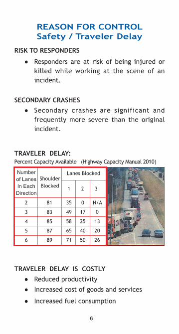
REASON FOR CONTROLSafety / Traveler Delay
RISK TO RESpONDERS
● Responders are at risk of being injured or killed while working at the scene of an incident.
SECONDARY CRAShES ● Secondary crashes are significant and
frequently more severe than the original incident.
TRAVELER DELAY IS COSTLY ● Reduced productivity
● Increased cost of goods and services
● Increased fuel consumption
TRAVELER DELAY:Percent Capacity Available (Highway Capacity Manual 2010)

7
COMpONENTS OF INCIDENT MANAGEMENT AREA

8
TRAFFIC CONTROL DEVICES (TCD)
FUNCTIONTo promote highway safety by providing for the orderly and predictable movement of all traffic and to provide guidance and warning as needed.
TYpES OF TCD ● Warning signs
● Channelizing devices
� Traffic cones
● Lighting devices
� Flashing warning beacon on equipment
� Flashing arrow panel on truck/trailer
● Shadow vehicles / advance warning truck (large truck, not occupied)
● Light sticks or flares (temporary or to supplement channelizing devices)

9
ADVANCE WARNING AREA
●● ●Warning Signs ● Flaggers ● Light Sticks or Flares ● Advance Warning Truck/Emergency Vehicle
What could you expect to see in the advance warning area?
WARNING SIGN SPACING (Feet)
more than 35 mph
MUTCD 2009, Table 6C-1

10
TRANSITION AREA
This area is used to channelize traffic from its normal path to a new path.
● Transition areas consist of tapers, which are created using a series of channelizing devices.
TYpES OF TApERS ● Merging - used to reduce the number of
through lanes in one direction (multi-lane road)
● Shifting - used to laterally shift traffic in one direction
● Shoulder - used to close a shoulder
● One-Lane, Two-Way Traffic - used with a flagger to close one lane on a two-lane road
● Downstream (optional) - provide visual cue that access is available to the original lane

11
Speed Limit (Mph)
Lane Width (Feet) Spacing Between Devices (Feet)10 11 12
25 105 115 125 25
35 205 225 245 35
45 450 495 540 45
55 550 605 660 55
65 650 715 780 65
70 700 770 840 70
TRANSITION AREA
*The following formulas are used to calculate taper length: Posted Speed Formula 40 mph or under L = WS2/60 45 mph or over L = WSWhere: L = taper length; W = width of lane or offset, and S = posted speed.
Note:• Spacing between devices for a one-lane, two-
way taper shall be 20 feet for all conditions.• Spacing in activity are is twice the speed
limit.
Length (L) of Taper in Feet*
TYpE OF TApER LENGTh (L)
Merging at least LShifting at least ½ LShoulder at least L
One-Lane,Two-Way 50-100 ft.Downstream 50-100 ft.

12
BUFFER SpACE(OpTIONAL)
This area separates traffic from the incident and provides recovery space for an errant vehicle.
● Traffic cones may be used to delineate longitudinal buffer space.
● No vehicle should be stopped in the buffer space.
LATERAL BUFFER SpACE
● Separates traffic from incident
● Separates opposing flows of traffic
● Width varies by incident
LONGITUDINAL BUFFER SPACE*
Speed (MPH) Distance (Feet)
25 155
35 250
45 360
55 495
65 645
70 730
*Also used as required sight distance to flagger station.

13
INCIDENT SpACE
This area includes the incident itself and any equipment, vehicles, or people working on the incident.
● Length varies by incident
● Safe refuge for emergency personnel
● Restricted to essential vehicles and equipment

14
INCIDENT ZONE pROCEDURE
FOUR phASE pROCEDURE
● Phase 1 - Provide Immediate Warning to Drivers
● Phase 2 - Establish Traffic Control
● Phase 3 - Monitor and Adjust
● Phase 4 - Hand Off or Remove
phASE 1 - pROVIDE IMMEDIATE WARNING
● Stop traffic if necessary.
● Place the Emergency Scene Ahead sign at:
� 500 feet for all highways except 1,000 feet for any 4 lane facility with a speed limit of 55 mph or greater
● Until standard traffic control devices are available, use your vehicle, flares, etc. to provide advance warning to drivers.
phASE 2 - ESTABLISh TRAFFIC CONTROL
● Assess the situation and determine your traffic control plan.
● Consider the location and extent (i.e. type of vehicles involved, severity) of the incident.
● Consider the number and position of lanes that need to be closed.

15
phASE 2 - ESTABLISh TRAFFIC CONTROL
● Determine the expected duration of the incident. � The average closure time for Kentucky:
� 32 minutes for all crashes � 2 ½ hours for fatal crashes
� 95% of all crashes in Kentucky have closures of 1 ½ hours or less.
� Key characteristics of a crash that provide a good indication of a closure lasting more than 2 hours: � Fatalities � Large number of vehicles � Hazardous material � Possible criminal charges
� Request additional resources from KYTC or others as needed.
●● ●Determine what traffic control elements are needed. � What is the speed of traffic? � What is the type of roadway? � What type of signs and spacing are
needed? � Is a flagger needed? � What type/length of taper is needed? � Is a shadow vehicle available for use?
●● ●Setup Phase 2 traffic control using a 3-step process.1. Establish start of transition (flagger
station if needed).2. Place advance warning signs.3. Establish tapers.

16
PHASE 3 - MONITOR AND ADJUST
● Observe traffic flow and determine if sign location and/or flagger adjustments are needed.
● Avoid traffic backups.
● Determine if traffic backup extends past a location where a driver can observe the first warning sign.
● Adjust advance warning area in response to length of traffic queue.
PHASE 4 - HAND OFF OR REMOVE
● When appropriate, relinquish control to law enforcement or KYTC.
●● ●Traffic control can be removed when:
� The roadway is clear of damaged vehicles, emergency vehicles, and debris.
� Traffic can be restored to normal flow.

17
FLAGGINGA stop/slow paddle is the primary and preferred hand-signaling device.
Flagger Stations
• Located far enough in advance of the work space so that approaching vehicles will have sufficient distance to stop before entering the activity area (See table on page 12)
• Preceded by proper advance warning signs• Illuminated at night
Flaggers
• Stand alone• Be clearly visible at all times and facing on-
coming traffic• Stand on the shoulder or in the closed lane prior
to traffic stopping• Only stand in the lane used by moving vehicles
when traffic is stopped• Be located far enough in advance of other
responders that an audible warning can be provided if there is an out-of-control vehicle
Communication
• When more than one flagger is needed, designate one as the coordinator and ensure good communication between the two.
• A phone, radio, or some other form of communication will be needed if the flaggers are not visible to one another.

18
The use of the flag and sign paddle are displayed in the following illustration.
pREFERRED METhOD EMERGENCY SITUATIONS ONLY STOP/SLOW PADDLE RED FLAG
For flagging, always use a responder who has had appropriate flagger training.

19
EqUIpMENT LIST
Recommended Equipment for Emergency Traffic Control [quantity]
● Warning Signs (48” x 48”, roll-up, retroreflective)
� “Emergency Scene Ahead” - [2]
� “Be Prepared to Stop” - [2]
� Flagger - [2]
� Portable Sign Stands - [6]
● Flags (optional)
� 18” x 18” orange safety flags to attach to warning signs - [18]
� 24” x 24” red flagger flags with stiffener and 36” staff - [2]
● Traffic Cones � 28”, orange with retroreflective bands
- [16]
● Stop/Slow Paddles � 24”, retroreflective with 7’ staff - [2]
● Retroreflective Safety Apparel (Class 2 or Class 3) � ANSI 107-2004 or ANSI 207-2006 Approved
Color - [for every responder]

20
SAFETY CLOThING
HIGH-VISIBILITY SAFETY APPAREL(Must meet ANSI 107-2004 or ANSI 207-2006 stan-dards)
Four classifications of apparel: ● Performance Class 1 - low speeds, ample
separation, full attention
● Performance Class 2 - higher speeds, complex backgrounds, diverted attention, less traffic / work separation possible Example: Short-term maintenance operation, firefighters engaged in emergency response activities who are wearing turnout gear
● Performance Class 3 - very high speeds, reduced sight distances, high task loads, need for conspicuity through full range of motion, need to be recognized as a person Example: Highway Emergency Incident
● Performance Class E - trousers, bib overalls, and shorts designed for use with Performance Class 2 or 3 apparel
Responders are required to wear Class 2 or Class 3 safety apparel when within the public right-of-way.
21
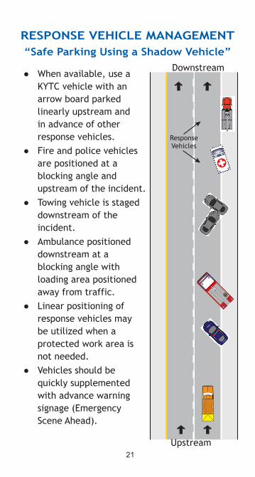
RESpONSE VEhICLE MANAGEMENT“Safe Parking Using a Shadow Vehicle”
● When available, use a KYTC vehicle with an arrow board parked linearly upstream and in advance of other response vehicles.
● Fire and police vehicles are positioned at a blocking angle and upstream of the incident.
● Towing vehicle is staged downstream of the incident.
● Ambulance positioned downstream at a blocking angle with loading area positioned away from traffic.
● Linear positioning of response vehicles may be utilized when a protected work area is not needed.
● Vehicles should be quickly supplemented with advance warning signage (Emergency Scene Ahead).
Downstream
Upstream

22
The diagrams on the following pages represent examples of the application of principles and procedures for safe and efficient TTC for traffic incidents. The layouts represent minimum requirements. It is not possible to include illustrations to cover every situation which will require work area protection. They are not intended as a substitute for judgment and should be altered to fit the conditions of a particular site. All traffic control devices used must be in compliance with the MUTCD. For further information and additional application diagrams, refer to Part 6 of the MUTCD.
Arrow Panel
Traffic Cone
Direction of Traffic
Flagger
Sign
Incident Space
Response Vehicle
Shadow Vehicle (attenuator optional)
TYpICAL AppLICATION DIAGRAMS
(Refer to table on the following page for distances)

23
NA
One-Lane,
Two-W
ay &
Dow
nstream
Spacing in activity area is twice the speed lim
it.

24
MERGING TApER(on a multi-lane road - one lane closed)
(L)
Refer to the chart on pg. 23 for spacing.

25
MERGING TApER(on a multi-lane road - interior lane closed)
(L)
Refer to the chart on pg. 23 for spacing.

26
ONE-LANE, TWO-WAY TRAFFIC TAPER
Refer to the chart on pg. 23 for spacing.
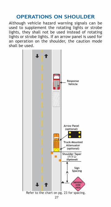
27
OpERATIONS ON ShOULDERAlthough vehicle hazard warning signals can be used to supplement the rotating lights or strobe lights, they shall not be used instead of rotating lights or strobe lights. If an arrow panel is used for an operation on the shoulder, the caution mode shall be used.
(Optional)
Refer to the chart on pg. 23 for spacing.

28
INCIDENT IN CENTER OF INTERSECTION
Refer to the chart on pg. 23 for spacing.

29
RIGhT LANE CLOSURE ON FAR SIDE OF INTERSECTION
If the incident space extends across the crosswalk, the crosswalk should be closed.
Refer to the chart on pg. 23 for spacing.
30
KENTUCKY qUICK CLEARANCE LAW
KRS 189.580
Applicable to an interstate highway or parkway or any on-ramp or off-ramp regarding accidents that do not involve death, injury or
hazardous material.
BASIC COMpONENTS:
● Driver Stop - Driver must stop in a way that does not hamper traffic.
● Driver Removal - Driver involved in a minor incident with no injuries is required to remove the vehicle from the lanes of traffic.
● Authority Removal - Safety or peace officers have the authority to remove a vehicle that is blocking traffic.
● Authority Tow - Safety or peace officers have the authority to have a vehicle towed or cargo removed from the roadway if it is in the interest of public safety.
● Cost Recovery - Any agency may recover costs expended.
Information and guidance was obtained from International Fire Service Training Association in the development of this handbook.

July
201
3
www.kyt2.com