Guideline of Camera & Imaging Products Association · The present guidelines define conventions for...
42
Guideline of Camera & Imaging Products Association CIPA DCG-X006-Translation-2011 Implementation Guidelines for DPS over IP Prepared by Standardization Committee Published by Camera & Imaging Products Association
Transcript of Guideline of Camera & Imaging Products Association · The present guidelines define conventions for...

Guideline of Camera & Imaging Products Association
CIPA DCG-X006-Translation-2011
Implementation Guidelines for DPS over IP
Prepared by
Standardization Committee
Published by
Camera & Imaging Products Association

Disclaimer and Copyright Notice THIS DRAFT DOCUMENT IS PROVIDED “AS IS” WITH NO WARRANTIES
WHATSOEVER, INCLUDING ANY WARRANTY OF MERCHANTABILITY,
NONINFRINGEMENT, FITNESS FOR ANY PARTICULAR PURPOSE, OR ANY
WARRANTY OTHERWISE ARISING OUT OF ANY PROPOSAL, SPECIFICATION OR
SAMPLE.
All liability, including liability for infringement of any proprietary rights, relating to use of
information in this document is disclaimed. No license, express or implied, by estoppel or
otherwise, to any intellectual property rights are granted herein.
This document is a draft for comment only and is subject to change without notice. Readers
shall not design products based on this document.
Copyright © 2011 CIPA All Rights Reserved

i
Overview
This document specifies implementation guidelines for using the DPS standard in LAN
environments, through the use of CIPA DC-001 (Digital Photo Solutions for Imaging
Devices) (hereinafter called “DPS standard”), typically called PictBridge, and CIPA DC-005
(“Picture Transfer Protocol” over TCP/IP networks (PTP-IP)) (hereinafter called “PTP-IP
standard”), which are defined by CIPA.
Methods of verifying interconnectivity between DPS devices in wireless LAN environments
and conformance specifications for use of logotypes will be separately defined.

ii
Contents
1. Background and Overview ......................................................................................... 1
1.1 Background ...................................................................................................... 1
1.2 Overview ........................................................................................................... 1
2. Scope ........................................................................................................................ 2
3. Definitions of Terms ................................................................................................... 3
3.1 Verbal Forms of Terms Representing Specification Level ................................. 3
3.2 Terms ............................................................................................................... 4
4. Communication Protocol Architecture of DPS over IP ............................................... 5
4.1 Communication Protocol Architecture of USB I/F-Based DPS .......................... 5
4.2 Communication Protocol Architecture of LAN I/F-Based DPS ........................... 6
5. Connection Topology in LAN Environments............................................................... 7
5.1 Physical Connection Topology .......................................................................... 7
5.2 Logical Connection Topology ............................................................................ 8
6. Setup of Wireless LAN .............................................................................................. 9
6.1 Setup Method ................................................................................................... 9
6.1.1 Simple Setup in Infrastructure Mode ........................................................ 9
6.1.2 Simple Setup in Ad Hoc Mode .................................................................. 9
6.1.3 Simple Setup in Wi-Fi DirectTM ................................................................. 9
6.1.4 Manual Input Settings in Infrastructure Mode ........................................... 9
7. Secure Connection .................................................................................................. 10
7.1 Wireless LAN Security .................................................................................... 10
7.1.1 Secure Connection of Infrastructure Mode ............................................. 10
7.1.2 Secure Connection of Ad Hoc Mode ...................................................... 10
7.1.3 Secure Connection of Wi-Fi DirectTM ...................................................... 10
8. IP Addressing .......................................................................................................... 11
8.1 IP Address Assignment ................................................................................... 11
8.1.1 Address Assignment in Wired LAN and Wireless LAN (Infrastructure
Mode) ..................................................................................................... 11
8.1.2 Address Assignment in Ad Hoc Mode .................................................... 11
8.1.3 Address Assignment in Wi-Fi DirectTM Connection ................................. 11

iii
8.2 IP Address Space ........................................................................................... 11
9. Security of IP Session ............................................................................................. 12
9.1 Assurance of IP Session ................................................................................. 12
10. PTP-IP Session ....................................................................................................... 13
10.1 Connection Timing of PTP-IP Logical Communication Path ............................ 13
10.2 Termination Timing of PTP-IP Logical Communication Path ........................... 15
11. References .............................................................................................................. 16
Normative Annex ........................................................................................................... 17
Annex A DPSPrinter Device Template .................................................................. 18
1. Overview and Scope ..................................................................................... 20
1.1 Introduction .......................................................................................... 20
1.2 Conventions ......................................................................................... 20
1.3 References ........................................................................................... 21
2. Device Definitions ......................................................................................... 22
2.1 Device Type ......................................................................................... 22
2.2 Device Model ....................................................................................... 22
2.3 Theory of Operation ............................................................................. 22
2.3.1 Device Discovery ......................................................................... 22
2.3.2 PTP Connection Establishment ................................................... 22
3. XML Device Description ................................................................................ 23
4. Test............................................................................................................... 24
Annex B DPSConnectionManager Service Template ........................................... 25
1. Overview and Scope ..................................................................................... 27
1.1 Introduction .......................................................................................... 27
1.2 Conventions ......................................................................................... 27
1.3 References ........................................................................................... 28
2. Service Modeling Definitions ......................................................................... 29
2.1 Service Type ........................................................................................ 29
2.2 State Variables ..................................................................................... 29
2.2.1 PTPResponderIPAddress ............................................................ 29
2.2.2 RequestResult ............................................................................. 29
2.3 Eventing and Moderation...................................................................... 30
2.4 Actions ................................................................................................. 30

iv
2.4.1 ConnectionRequest ..................................................................... 30
2.4.1.1 Arguments ....................................................................... 30
2.4.1.2 Errors ............................................................................... 30
2.5 Theory of Operation ............................................................................. 31
2.5.1 Connection Request .................................................................... 31
2.5.2 Initiating the PTP connection ....................................................... 31
3. XML Service Description ............................................................................... 32
4. Test............................................................................................................... 33
Appendix A.PTP Connection Establishment Sequence (Informative) .................. 34
A.1. Discovery: Advertisement ....................................................................... 34
A.2. Discovery: Search .................................................................................. 35

1
1. Background and Overview
1.1 Background
The DPS standard is independent of the physical I/F. However, the only physical I/F
specified in the implementation guidelines is USB.
In 2005, CIPA established the PTP-IP standard for PTP (Picture Transfer Protocol)
communication on TCP (Transfer Control Protocol), but did not specify implementation
guidelines for DPS, assuming the PTP-IP standard, thereby causing a problem in
interconnectivity.
1.2 Overview
The objective of the present guidelines is to compile mutually-respected conventions into
guidelines, for various settings that have not yet been determined in LAN I/F connection
environments and unclear technical items for realizing DPS services using the PTP-IP
standard.

2
2. Scope
The present guidelines define conventions for expansion to LAN connection environments, in
addition to USB supported as the sole physical I/F of the DPS standard.
The present guidelines apply to image input devices such as DSC and image output devices
such as printers, which are connected to each other in a LAN environment and have a direct
print function.

3
3. Definitions of Terms
3.1 Verbal Forms of Terms Representing Specification
Level
Pursuant to ISO/IEC rules, terms in this document shall be construed as described below.
(See Directives 2 Annex H “Verbal forms for the expression of provisions”.)
Requirements
Verbal forms Equivalent expressions
shall
is mandatory
shall not
is not allowed
Recommendations
Verbal forms Equivalent expressions
should
it is recommended that
is recommended
should not
Permissions
Verbal forms Equivalent expressions
may
is optional
need not
is not required
Possibility and Capability
Verbal forms Equivalent expressions
can
it is possible to
cannot

4
3.2 Terms
DSC Digital Still Camera
PRT Printer
AP Access Point
Wi-Fi® Wi-Fi®
WPA2TM
Wi-Fi Protected Access® 2
WPS Wi-Fi Protected SetupTM
(TBD)
PSK Pre Shared Key
UPnPTM
Universal Plug and Play

5
4. Communication Protocol Architecture of
DPS over IP
A Communication Protocol Architecture of LAN I/F-based DPS is described below in
comparison with a USB I/F-based Communication Protocol Architecture.
4.1 Communication Protocol Architecture of USB I/F-
Based DPS
USB I/F-based DPS is described in detail in the DPS standard in CIPA.
USB I/F is characterized by the adoption of SICD (Still Image Capture Device) as a USB
device class for connecting PTP, an image transfer protocol.
Figure 4-1
USB Connection
Printer
USB (Host)
PTP (Initiator)
DPS
PictBridge (Server)
SICD (Initiator)
Digital Camera
USB (Device)
PTP (Responder)
DPS
PictBridge (Client)
SICD (Responder)

6
4.2 Communication Protocol Architecture of LAN I/F-
Based DPS
Figure 4-2 is a Communication Protocol Architecture of LAN I/F-based DPS.
Wired LAN/wireless LAN shall be used as the physical I/F. The PTP-IP standard (CIPA DC-
005-2005 “Picture Transfer Protocol over TCP/IP networks”) standardized by CIPA shall be
adopted as the protocol for connecting the above TCP/IP layer and PTP, an image transfer
protocol, to each other using a TCP session.
In order to select a device to be connected in a PTP session from among devices in the
network, DPSPrinterDevice and DPSConnectionManagerService defined by CIPA on the
basis of UPnP DA1.0 shall be adopted.
Figure 4-2
LAN Connection
Printer
UDP/TCP
LAN/WLAN
IP
http
SSDP SOAP
UPnP DA
DPSPrinter
DPSConnectionManager
PTP (Initiator)
DPS
PictBridge (Server)
PTP-IP (Initiator)
Digital Camera
UDP/TCP
LAN/WLAN
IP
PTP (Responder)
DPS
PictBridge (Client)
PTP-IP (Responder) http
SSDP SOAP
UPnP DA
Control Point

7
5. Connection Topology in LAN
Environments
The LAN connection topology in DPS over IP is specified as follows.
5.1 Physical Connection Topology
Figure 5-1 shows an example of a physical connection topology in DPS over IP.
Access Point / HUB
Printer n
Printer 1
DSC m
DSC 1
Figure 5-1
As shown in the example of Figure 5-1, in the case of using LAN I/F, it shall be assumed, in a
physical connection topology, that DSCs and PRTs are connected to each other and even a
Multi Point-Multi Point connection topology is configured.
Connection via 100BASE-TX of the IEEE802.3 standard shall be adopted as a physical I/F
for using wired LAN I/F; another connection may be adopted. Connection via an
infrastructure mode of any IEEE802.11b/g/n (2.4 GHz band) should be adopted as a physical
I/F for using wireless LAN I/F; another connection may be adopted.

8
5.2 Logical Connection Topology
Figure 5-2 shows an example of a logical connection topology of DPS over IP.
AP/HUB
PRT 1
DSC 1
Figure 5-2
In order to implement DPS services between DSC1 and PRTn in a physical connection
topology shown in the example of Figure 5-1, a Point-Point logical communication path as
shown in Figure 5-2 shall be configured for DPS to establish a PTP-IP session.
The connection and termination of the PTP-IP session will be described in Section 10.

9
6. Setup of Wireless LAN
6.1 Setup Method
Setup Method on operation modes of wireless LAN (802.11 series) is specified as follows.
6.1.1 Simple Setup in Infrastructure Mode
A simple connection scheme should comply with the WPS scheme implemented in many Wi-
Fi-certified APs; a simple connection scheme other than WPS may be adopted.
In addition to the WPS-PIN scheme, which shall be employed when WPS is adopted, the
WPS-PBC scheme should be adopted; another scheme may be adopted.
In the case of adopting WPS, the certification requirements of “Wi-Fi Protected Setup
“ specified by Wi-Fi Alliance® shall be met.
6.1.2 Simple Setup in Ad Hoc Mode
(TBD)
6.1.3 Simple Setup in Wi-Fi DirectTM
In addition to the WPS-PIN scheme, which shall be adopted in WPS specifications, the WPS-
PBC scheme should be adopted; another scheme may be adopted.
In the case of adopting WPS, the certification requirements of “Wi-Fi Protected
Setup“ specified by Wi-Fi Alliance® shall be met.
6.1.4 Manual Input Settings in Infrastructure Mode
In order to allow connection to devices not complying with the simple setting scheme, a
function for assigning setting information of wireless LAN by manual input should be
provided.

10
7. Secure Connection
7.1 Wireless LAN Security
In a wireless LAN communication path using wireless communication media, compliance
with the security specifications specified in Wi-Fi® prevents leakage of communication
details to third parties who intercept communication.
7.1.1 Secure Connection of Infrastructure Mode
It is strongly recommended that WPA2™ be adopted for communication security of the
infrastructure mode; a scheme other than WPA2™ may be adopted.
In the case of adopting WPA2™, the certification requirements of “Wi-Fi 802.11/ WPA2TM
/WPATM
“ specified by Wi-Fi Alliance® shall be met.
7.1.2 Secure Connection of Ad Hoc Mode
(TBD)
7.1.3 Secure Connection of Wi-Fi DirectTM
It is strongly recommended that WPA2™ be adopted; a scheme other than WPA2™ may be
adopted.
In the case of adopting WPA2™, the certification requirements of “Wi-Fi 802.11/ WPA2TM
/WPATM”
specified by Wi-Fi Alliance® shall be met.

11
8. IP Addressing
8.1 IP Address Assignment
After connection of the physical layer at the LAN level is completed between devices, IP
address assignment for providing IP addresses shall be performed as described below.
8.1.1 Address Assignment in Wired LAN and Wireless LAN
(Infrastructure Mode)
A DHCP client and Auto-IP shall be implemented. A setting means utilizing device UI input
should be adopted.
8.1.2 Address Assignment in Ad Hoc Mode
(TBD)
8.1.3 Address Assignment in Wi-Fi DirectTM Connection
Devices complying with “Wi-Fi Direct” shall implement both a DHCP server and a DHCP
client.
8.2 IP Address Space
In the present guidelines, IPv4, which is widely used in private networks such as home
networks, shall be complied with.
IPv6 used in wide-area IP networks may be complied with.

12
9. Security of IP Session
9.1 Assurance of IP Session
The present guidelines do not particularly specify a method of assuring security on the IP
session. Methods such as IPSec may be utilized, and security on the IP session may be
assured, as necessary.

13
10. PTP-IP Session
Connection and termination of a PTP-IP session are specified in the following sections.
10.1 Connection Timing of PTP-IP Logical Communication
Path
After completion of the LAN communication path connection (MAC Connect) and IP
addressing, prior to setup on a logical communication path for a PTP-IP session specified in
Section 5.2, a process of searching for a printer (PTP-IP Initiator) shall be executed. After a
trigger from a user’s operation input device establishes P2P connection, connection via a
PTP-IP logic communication path shall be made with DSC that has been fixedly connected,
on the initiative of the printer (PTP-IP Initiator).
On searching for the PTP-IP Initiator and a method of establishing P2P connection, UPnP
DA1.0, “DPSPrinterDevice” and “DPSConnectionManagerService” shall be referred to.

14
USER
Storage
Device
Storage
Server
Client
Server
Storage
Client
Device
DPS_ConfigurePrintService
DPS_GetCapability Select print mode and pictures to create “Job”
DPS_StartJob
DPS_GetFileInfo Storage Data
“File Info”
DPS_GetFile Storage Data
“Image File”
Print Data
DPS_NotifyDeviceStatus(“Printing”)
DPS_NotifyJobStatus(Page 1/1)
DPS_NotifyJobStatus(Page 1/1)
DSC DPS Discovery Printer DPS Discovery DPS Discovery
DSC PTP-IP Connect Printer PTP-IP Connect PTP-IP Connect
DSC Target Select Printer Target Select PTP-IP Target Select
DSC IP Addressing Printer IP Addressing IP Connect
DSC IP Wi-Fi Setting Printer Wi-Fi Setting MAC Connect
Wi-Fi Setup
Wi-Fi Setup
DSC PTP-IP Discovery Printer PTP-IP Discovery PTP-IP Discovery
Select Printer
Figure 10-1 DPS over IP Job Flow (Case of User’s Operation Input on DSC Side) Example

15
10.2 Termination Timing of PTP-IP Logical
Communication Path
Pursuant to the specifications of Section 2.2.3.3 in the PTP-IP standard (CIPA DC-005-2005
“Picture Transfer Protocol over TCP/IP networks”), in either of the two cases:
1) where Initiator determines that maintenance of the logical communication path is
unnecessary, or
2) where Initiator or Responder detects a communication error and determines that the
logical communication path is difficult to be maintained,
then Teardown of PTP-IP (closing the TCP Port) shall be made.
Note that “DPSPrinter Device” on the Initiator side should transmit a message for leaving the
network (ssdp:byebye), prior to Teardown.
When PRT (Initiator) determines that maintenance of the logical communication path is
unnecessary, the necessity of maintaining the PTP-IP communication path should be
determined in consideration of the time required for the user’s continuous printing operation
and the like.

16
11. References
In the case of citing and referring to documents in the present document, the following
abbreviations are used to indicate cited parties.
DPS Digital Photo Solutions for Imaging Devices
CIPA DC-001-2003 Rev2.0
http://www.cipa.jp/
PTP-IP “Picture Transfer Protocol” over TCP/IP networks
CIPA DC-005-2005
http://www.cipa.jp/
WPA2™ The State of Wi-Fi® Security: Wi-Fi CERTIFIED™ WPA2™
Delivers Advanced Security to Homes, Enterprises and Mobile
Devices (2009)
http://www.wi-fi.org/
WPS Wi-Fi Protected Setup™ : Easing the User Experience for Home and
Small Office Wi-Fi® Networks (2010)
Wi-Fi Simple Configuration Specification v2.0.0
http://www.wi-fi.org/
Wi-Fi Direct™ Wi-Fi CERTIFIED Wi-Fi Direct™: Personal, portable Wi-Fi® to
connect devices anywhere, any time (2010)
Wi-Fi CERTIFIED Wi-Fi Direct™: Personal, portable Wi-Fi®
technology (2010)
Wi-Fi Peer-to-Peer (P2P) Specification v1.1
http://www.wi-fi.org/
(TBD)
(TBD)
Directives 2 ISO/IEC Directives, Part 2 “Rules for the structure and drafting of
International Standards”
http://www.iso.org/
UPnP DA1.0 UPnP Device Architecture (UDA), version 1.0
http://upnp.org/specs/arch/UPnP-arch-DeviceArchitecture-v1.0.pdf
DPSPrinter CIPA Digital Photo Solutions for Imaging Devices
DPSPrinter:1 Device Template Version 1.01
DPSConnection
Manager
CIPA Digital Photo Solutions for Imaging Devices
DPSConnectionManager:1 Service Template Version 1.01

17
Normative Annex

18
Annex A DPSPrinter Device Template
CIPA
Digital Photo Solutions for
Imaging Devices
DPSPrinter:1
Device Template Version 1.01
Revision 1.0
October 19, 2011

19
Contents
1. Overview and Scope .......................................................................................................... 20
1.1 Introduction ............................................................................................................... 20
1.2 Conventions .............................................................................................................. 20
1.3 References ................................................................................................................. 21
2. Device Definitions ............................................................................................................. 22
2.1 Device Type ............................................................................................................... 22
2.2 Device Model ............................................................................................................. 22
2.3 Theory of Operation .................................................................................................. 22
2.3.1 Device Discovery ............................................................................................. 22
2.3.2 PTP connection establishment ......................................................................... 22
3. XML Device Description .................................................................................................. 23
4. Test .................................................................................................................................... 24

20
1. Overview and Scope
1.1 Introduction
This device template is compliant with the UPnPTM
Architecture, Version 1.0 as a vendor
extended device. It defines a DPSPrinter device over IP network.
CIPA DC-001-2003 defines the “Digital Photo Solutions for Imaging Devices (DPS)”
specifications, which enable direct printing between an image source device such as a DSC,
and an image output device such as a printer. The DPS architecture is designed to operate at
the application layer and to be independent of the details of the underlying data transport. The
first-generation solution was deployed over USB. This template defines the next-generation
solution that will be deployed over IP network, utilizing the PTP-IP that enables a PTP
connection over IP network. See [DPS], [PTP] and [PTP-IP] for more information.
Figure 1-1: DPS over IP network protocol stack
DPSPrinter:1 provides the following functionality:
・ DPS Connection Manager (DPSConnectionManager).
This template does not address:
・ DPS Discovery
・ DPS Print Service
・ DPS Storage Service
1.2 Conventions
The keywords “MUST,” “MUST NOT,” “REQUIRED,” “SHALL,” “SHALL NOT,”
“SHOULD,” “SHOULD NOT,” “RECOMMENDED,” “MAY,” and “OPTIONAL” in this
document are to be interpreted as described in [RFC2119].
DPS Application
DPS Layer
PTP
PTP-IP
TCP/IP
Network
Independence of the details of the underlying data transport

21
1.3 References
[DEVICE] – UPnP Device Architecture (UDA), version 1.0
Available at: http://upnp.org/specs/arch/UPnP-arch-DeviceArchitecture-v1.0.pdf
[DPS] – CIPA DC-001-2003 Rev2.0, Digital Photo Solutions for Imaging Devices
Available at: http://www.cipa.jp/pictbridge/index_e.html
[PTP] – “Photography – Electronic still picture imaging – Picture transfer protocol (PTP) for
digital still photography devices,” ISO 15740:2008
Available at: http://www.iso.org/
[PTP-IP] – CIPA DC-005-2005, “Picture Transfer Protocol” over TCP/IP networks (PTP-IP)
Available at: http://www.cipa.jp
[RFC2119] – IETF RFC2119 - Key words for use in RFCs to Indicate Requirement Levels,
March 1997
Available at: http://www.ietf.org/rfc/rfc2119.txt
22
2. Device Definitions
2.1 Device Type
The following device type identifies a device that is compliant with this template:
urn:schemas-cipa-jp:device:DPSPrinter:1
2.2 Device Model
DPSPrinter products MUST implement minimum version numbers of all REQUIRED
services specified in the table below.
Table 2-1: Device Requirements
DeviceType Root R/O1 ServiceType R/O
1 Service ID
2
DPSPrinter:1 Root R DPSConnectionManager:1 R DPSConnectionManager 1 R = Required, O = Optional, X = Non-standard
2 Prefixed by urn:cipa-jp:serviceId:
2.3 Theory of Operation
2.3.1 Device Discovery
A control point (DPS Print Client, such as a DSC) can discover DPSPrinter devices by the
Simple Service Discovery (SSDP) as defined in [DEVICE].
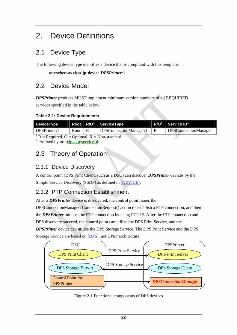
2.3.2 PTP Connection Establishment
After a DPSPrinter device is discovered, the control point issues the
DPSConnectionManager: ConnectionRequest() action to establish a PTP connection, and then
the DPSPrinter initiates the PTP connection by using PTP-IP. After the PTP connection and
DPS discovery succeed, the control point can utilize the DPS Print Service, and the
DPSPrinter device can utilize the DPS Storage Service. The DPS Print Service and the DPS
Storage Service are based on [DPS], not UPnP architecture.
Figure 2-1 Functional components of DPS devices
DSC DPSPrinter
DPSConnectionManage
r
DPS Print Server DPS Print Client DPS Print Service
DPS Storage Client DPS Storage Server DPS Storage Service
Control Point for
DPSPrinter

23
3. XML Device Description <?xml version="1.0"?>
<root xmlns="urn:schemas-upnp-org:device-1-0">
<specVersion>
<major>1</major>
<minor>0</minor>
</specVersion>
<URLBase>base URL for all relative URLs</URLBase>
<device>
<deviceType>urn:schemas-cipa-jp:device:DPSPrinter:1</deviceType>
<friendlyName>short user-friendly title</friendlyName>
<manufacturer>manufacturer name</manufacturer>
<manufacturerURL>URL to manufacturer site</manufacturerURL>
<modelDescription>long user-friendly title</modelDescription>
<modelName>model name</modelName>
<modelNumber>model number</modelNumber>
<modelURL>URL to model site</modelURL>
<serialNumber>manufacturer's serial number</serialNumber>
<UDN>uuid:UUID</UDN>
<UPC>Universal Product Code</UPC>
<iconList>
<icon>
<mimetype>image/format</mimetype>
<width>horizontal pixels</width>
<height>vertical pixels</height>
<depth>color depth</depth>
<url>URL to icon</url>
</icon>
XML to declare other icons, if any, go here
</iconList>
<serviceList>
<service>
<serviceType>
urn:schemas-cipa-jp:service:DPSConnectionManager:1
</serviceType>
<serviceId>urn:cipa-jp:serviceId:DPSConnectionManager</serviceId>
<SCPDURL>URL to service description</SCPDURL>
<controlURL>URL for control</controlURL>
<eventSubURL></eventSubURL>
</service>
Declarations for other services added by UPnP vendor (if any) go here
</serviceList>
<deviceList>
Description of embedded devices added by UPnP vendor (if any) go here
</deviceList>
<presentationURL>URL for presentation</presentationURL>
</device>
</root>

24
4. Test
There are no semantics tests defined for this device.

25
Annex B DPSConnectionManager Service Template
CIPA
Digital Photo Solutions for
Imaging Devices
DPSConnectionManager:1
Service Template Version 1.01
Revision 1.0
October 19, 2011

26
Contents
1. Overview and Scope .......................................................................................................... 27
1.1 Introduction .................................................................................................................. 27
1.2 Conventions ................................................................................................................. 27
1.3 References .................................................................................................................... 28
2. Service Modeling Definitions ............................................................................................ 28
2.1 Service Type ................................................................................................................ 29
2.2 State Variables ............................................................................................................. 29
2.2.1 PTPResponderIPAddress ................................................................................. 29
2.2.2 RequestResult .................................................................................................. 29
2.3 Eventing and Moderation ............................................................................................. 30
2.4 Actions ......................................................................................................................... 30
2.4.1 ConnectionRequest .......................................................................................... 30
2.4.1.1 Arguments ........................................................................................ 30
2.4.1.2 Errors ................................................................................................ 30
2.5 Theory of Operation..................................................................................................... 31
2.5.1 Connection Request ......................................................................................... 31
2.5.2 Initiating the PTP connection .......................................................................... 31
3. XML Service Description .................................................................................................. 32
4. Test .................................................................................................................................... 33
Appendix A. PTP Connection Establishment Sequence (Informative) ................................... 34
A.1 Discovery: Advertisement .......................................................................................... 34
A.2 Discovery: Search ...................................................................................................... 35

27
1. Overview and Scope
This service definition is compliant with the UPnPTM
Device Architecture, Version 1.0 as a
vendor extended service. It defines a service type referred to herein as
DPSConnectionManager service.
1.1 Introduction
This service enables the PTP connection between a DPSPrinter device as a PTP Initiator and
a control point as a PTP Responder. The PTP connection is established by using PTP-IP. See
[PTP] and [PTP-IP] for more information.
Figure 1-1 DPS Communication Stack
The DPSConnectionManager service provides control points with the following
functionality:
・ Initiating the PTP connection
This service does not provide the following functionality:
・ PTP connection establishment process
・ PTP connection
1.2 Conventions
The keywords “MUST,” “MUST NOT,” “REQUIRED,” “SHALL,” “SHALL NOT,”
“SHOULD,” “SHOULD NOT,” “RECOMMENDED,” “MAY,” and “OPTIONAL” in this
document are to be interpreted as described in [RFC2119].
Notice: “******” means hidden value.
DPS Application
DPS Layer
(DPS Print Client)
PTP
(Responder)
PTP-IP
TCP/IP
Network
Control Point
DPS Application
DPS Layer
(DPS Print Server)
PTP
(Initiator)
PTP-IP
TCP/IP
Network
DPSPrinter
DPS Protocol
PTP Protocol
PTP-IP Protocol
TCP/IP Protocol
Network-specific Protocol

28
1.3 References
[DEVICE] – UPnP Device Architecture (UDA), version 1.0
Available at: http://upnp.org/specs/arch/UPnP-arch-DeviceArchitecture-v1.0.pdf
[DPS] – CIPA DC-001-2003 Rev2.0, Digital Photo Solutions for Imaging Devices
Available at: http://www.cipa.jp/pictbridge/index_e.html
[PTP] – “Photography – Electronic still picture imaging – Picture transfer protocol (PTP) for
digital still photography devices”, ISO 15740:2008
Available at: http://www.iso.org/
[PTP-IP] – CIPA DC-005-2005, “Picture Transfer Protocol” over TCP/IP networks (PTP-IP)
Available at: http://www.cipa.jp
[RFC3986] – IETF RFC3986 - Uniform Resource Identifier (URI): Generic Syntax
Available at: http://www.ietf.org/rfc/rfc3986.txt
[RFC2119] – IETF RFC2119 - Key words for use in RFCs to Indicate Requirement Levels,
March 1997
Available at: http://www.ietf.org/rfc/rfc2119.txt

29
2. Service Modeling Definitions
2.1 Service Type
The following service type identifies a service that is compliant with this template:
urn:schemas-cipa-jp:service:DPSConnectionManager:1
2.2 State Variables
The state variables of this service are shown below.
Table 2-1 State Variables
Variable Name R/O1 Data Type
Allowed Value Default
Value
PTPResponderIPAddress R string IP Address and port number, PTPResponderIPAddress = IPv4address [“:” port], IPv4address and port as defined in [RFC3986]
Not specified
RequestResult R string ******,
******,
******
Not specified
Vendor-defined X TBD TBD TBD
1 R = Required, O = Optional, X = Non-standard
2.2.1 PTPResponderIPAddress
This variable indicates the IP address and port number of a device that is the PTP Responder.
If the port (including “:”) is omitted, the port number is 15740. The DPSPrinter attempts to
establish the PTP connection with the device. The device MUST be the same as the control
point that issues a connection request.
2.2.2 RequestResult
This variable represents the result of a connection request by a control point.
Table 2-2 allowedValueList for RequestResult
Value R/O Description
****** R Connection request is accepted.
****** R Connection request is rejected.
****** O Connection request failed because the DPSPrinter is busy.
Vendor-defined X TBD

30
2.3 Eventing and Moderation
Table 2-3 Event Moderation
Variable Name Evented Moderated Event
Max Event Rate
Logical Combination
Min Delta per Event
PTPResponderIPAddress No n/a n/a n/a
RequestResult No n/a n/a n/a
Vendor-defined TBD TBD TBD TBD TBD
2.4 Actions
The actions of this service are shown below:
Table 2-4 Actions
Name R/O
ConnectionRequest R
Vendor-defined X
2.4.1 ConnectionRequest
This action is used to request a PTP connection. If the request is accepted, the DPSPrinter
initiates the PTP connection with the device that issued this action by using PTP-IP as defined
in [PTP-IP].
2.4.1.1 Arguments
Table 2-5 Arguments of ConnectionRequest
Argument Direction Related State Variable
PTPResponderIPAddress IN PTPResponderIPAddress
RequestResult OUT RequestResult
2.4.1.2 Errors
Table 2-6 Errors of ConnectionRequest
Error Code Error Description Description
402 Invalid Args See UPnP Device Architecture section on
Control.
501 Action Failed See UPnP Device Architecture section on
Control.

31
2.5 Theory of Operation
The DPSPrinter device is a PTP Initiator, and shall initiate a PTP connection. However, since
the DPSPrinter device is a service provider, the DPSPrinter device can not initiate the PTP
connection without a trigger by a control point which is a connection request. To establish the
PTP connection, the control point issues the connection request, utilizing a
ConnectionRequest() action, to the DPSPrinter device, and then the DPSPrinter device
initiates the PTP connection. After the PTP connection and DPS discovery succeed, the DPS
services are available. See [DPS] for details regarding the DPS discovery and DPS services.
2.5.1 Connection Request
When the control point discovers the DPSConnectionManager service in the DPSPrinter
device, the control point can issue a ConnectionRequest() action to establish the PTP
connection. If RequestResult of the ConnectionRequest() response is “******”, the
DPSPrinter device initiates the PTP connection. If the RequestResult is not “******”, the
request failed for some reason (e.g. the request is rejected, the device is busy).
2.5.2 Initiating the PTP connection
When the connection request is accepted, the DPSPrinter device attempts to establish the
PTP connection by utilizing the PTP-IP. The PTP connection establishment process is out of
scope of this template. See [PTP] and [PTP-IP] for more information.

32
3. XML Service Description
<?xml version="1.0"?>
<scpd xmlns="urn:schemas-upnp-org:service-1-0">
<specVersion>
<major>1</major>
<minor>0</minor>
</specVersion>
<actionList>
<action>
<name>ConnectionRequest</name>
<argumentList>
<argument>
<name>PTPResponderIPAddress</name>
<direction>in</direction>
<relatedStateVariable>PTPResponderIPAddress</relatedStateVariable>
</argument>
<argument>
<name>RequestResult</name>
<direction>out</direction>
<relatedStateVariable>RequestResult</relatedStateVariable>
</argument>
</argumentList>
</action>
</actionList>
<serviceStateTable>
<stateVariable sendEvents="no">
<name>PTPResponderIPAddress</name>
<dataType>string</dataType>
</stateVariable>
<stateVariable sendEvents="no">
<name>RequestResult</name>
<dataType>string</dataType>
<allowedValueList>
<allowedValue>******</allowedValue>
<allowedValue>******</allowedValue>
<allowedValue>******</allowedValue>
</allowedValueList>
</stateVariable>
</serviceStateTable>
</scpd>

33
4. Test
There are no semantics tests defined for this device.

34
Appendix A. PTP Connection Establishment
Sequence (Informative)
A.1. Discovery: Advertisement
A PTP connection establishment sequence utilizing Discovery: Advertisement as defined in
[DEVICE] is shown below.
Figure A.1 PTP connection establishment sequence - Advertisement
Control Point
PT
P
(Responder)
DPS
IP N
etw
ork
PT
P-I
P
(Responder)
Wait for IP network connection
DPSPrinter
PT
P
(Initia
tor)
DPS
IP N
etw
ork
PT
P-I
P
(Initia
tor)
Wait for IP network connection
UD
A
Notify with SSDP:alive
Get Device Description
“Device Description”
Get Service Description
“Service Description”
…
ConnectionRequest()
“******”
InitCmdReq
InitCmdAck
InitEvtReq
InitEvtAck
PTP connection establishment
IP network connection establishment
DPS Discovery
PictBridgePrinter device Discovered
Control Point (PTP Responder) Discovered
UD
A
Attempt to establish the PTP connection

35
A.2. Discovery: Search
A PTP connection establishment sequence utilizing Discovery: Search as defined in
[DEVICE] is shown below.
Figure A.2 PTP connection establishment sequence - Search
Control Point P
TP
(Responder)
DPS
IP N
etw
ork
PT
P-I
P
(Responder)
Wait for IP network connection
DPSPrinter
PT
P
(Initia
tor)
DPS
IP N
etw
ork
PT
P-I
P
(Initia
tor)
Wait for IP network connection
M-SEARCH Response
Get Device Description
“Device Description”
Get Service Description
“Service Description”
ConnectionRequest()
“******”
InitCmdReq
InitCmdAck
InitEvtReq
InitEvtAck
PTP connection establishment
IP network connection establishment
DPS Discovery
Request with M-SEARCH PictBridgePrinter device Discovered
Control Point (PTP Responder) Discovered
UD
A
UD
A
Attempt to establish the PTP connection

36
Any and all standards and guidelines published by CIPA have been set forth without examining any possibility of infringement or violation of Intellectual Property Rights (patent right, utility model right, trademark right, design right, copyright and any other rights or legal interests of the same kind).
In no event shall CIPA be liable in terms of Intellectual Property Rights for the contents of such standards and guidelines.
CIPA DCG- x006-Translation-2011
Published by Camera & Imaging Products Association JCII BLDG., 25, Ichiban-cho, Chiyoda-ku, Tokyo, 102-0082 Japan
TEL +81-3-5276-3891 FAX +81-3-5276-3893
All rights reserved
No part of this guideline may be reproduced in any form or by any
means without prior permission from the publisher.