Guided Wave Radar Level Transmitter -...
36
Guided Wave Radar Level Transmitter Enhanced Model 705 with FOUndatIOn Fieldbus ™ digital Output 705 software v3.x FOUndatIOn Fieldbus ™ Operating Manual Use in conjunction with I&O manual BE 57-600
Transcript of Guided Wave Radar Level Transmitter -...
Guided Wave Radar
Level Transmitter
Enhanced Model 705 withFOUndatIOn Fieldbus™ digital Output
705 software v3.x
FOUndatIOn Fieldbus™ Operating Manual
Use in conjunction with I&O manual BE 57-600

Table of Contents
1.0 FOUNDATION fieldbus™ Overview........................................................................................................................................31.1 Description .......................................................................................................................................................................31.2 Benefits .............................................................................................................................................................................41.3 Device Configuration........................................................................................................................................................41.4 Intrinsic Safety ..................................................................................................................................................................51.5 Link Active Scheduler (LAS).............................................................................................................................................6
2.0 QuickStart Configuration ...................................................................................................................................................73.0 Function Blocks ..................................................................................................................................................................8
3.1 Overview ..........................................................................................................................................................................83.1.1 Universal Fieldbus Block Parameters.......................................................................................................................8
3.2 Resource Block..................................................................................................................................................................93.3 Transducer Block.............................................................................................................................................................12
3.3.1 Transducer Block Parameters ................................................................................................................................123.3.2 Password Parameters .............................................................................................................................................123.3.3 Configuration Parameters .....................................................................................................................................133.3.4 Offset Description ................................................................................................................................................14
3.4 Calibration Parameters....................................................................................................................................................153.4.1 Factory Parameters................................................................................................................................................153.4.2 Firmware Version..................................................................................................................................................16
3.5 Analog Input Block.........................................................................................................................................................163.5.1 AI Block Parameters..............................................................................................................................................163.5.2 Local Display of Analog Input Transducer Block Parameters ................................................................................183.5.2.1 AI Out Display Screens..................................................................................................................................19
3.6 PID Block.......................................................................................................................................................................203.6.1 PID Block Parameters...........................................................................................................................................20
4.0 Model 705 FOUNDATION fieldbus™ Menu .........................................................................................................................234.1 Measurement Type: Level Only.......................................................................................................................................23
5.0 Diagnostic Parameters.......................................................................................................................................................265.1 Simulation Feature..........................................................................................................................................................27
6.0 Reference Information ......................................................................................................................................................286.1 Troubleshooting ..............................................................................................................................................................28
6.1.1 Troubleshooting System Problems.........................................................................................................................286.1.2 Status Messages.....................................................................................................................................................296.1.3 FF Segment Checklist...........................................................................................................................................31
6.2 References .......................................................................................................................................................................32Appendix – Transducer Block Parameters ..................................................................................................................32Configuration Data Sheet ..........................................................................................................................................33
FOUNDATION Fieldbus™ Enhanced Eclipse Model 705Guided Wave Radar Transmitter
57-640 Eclipse Guided Wave Radar Transmitter - FOUNDATION fieldbus™
357-640 Eclipse Guided Wave Radar Transmitter - FOUNDATION fieldbus
1.0 FOUNDATION Fieldbus™ Overview
1.1 Description
FOUNDATION fieldbus™ is a digital communications systemthat serially interconnects devices in the field. A Fieldbussystem is similar to a Distributed Control System (DCS)with two exceptions:
• Although a FOUNDATION fieldbus™ system can use the samephysical wiring as an existing 4–20 mA device, Fieldbusdevices are not connected point to point, but rather aremultidropped and wired in parallel on a single pair of wires(referred to as a segment).
• FOUNDATION fieldbus™ is a system that allows the user todistribute control across a network. Fieldbus devices aresmart and actually maintain control over the system.
Unlike 4–20 mA analog installations in which the two wirescarry a single variable (the varying 4–20 mA current), a digi-tal communications scheme such as FOUNDATION fieldbus™
considers the two wires as a network. The network can carrymany process variables as well as other information. TheEnhanced Eclipse Model 705FF transmitter is aFOUNDATION fieldbus™ registered device that communicateswith the H1 FOUNDATION fieldbus™ protocol operating at31.25 kbits/sec. The H1 physical layer is an approvedIEC 61158 standard.
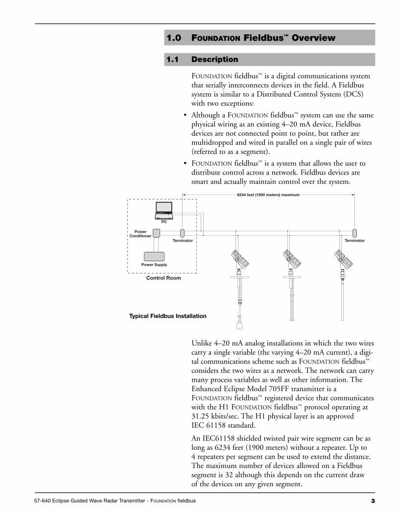
An IEC61158 shielded twisted pair wire segment can be aslong as 6234 feet (1900 meters) without a repeater. Up to4 repeaters per segment can be used to extend the distance.The maximum number of devices allowed on a Fieldbussegment is 32 although this depends on the current drawof the devices on any given segment.
Control Room
Power Supply
Terminator
6234 feet (1900 meters) maximum
PC
Terminator
PowerConditioner
typical Fieldbus Installation
4 57-640 Eclipse Guided Wave Radar Transmitter - FOUNDATION fieldbus
Details regarding cable specifications, grounding, termination,and other network information can be found in IEC 61158or the wiring installation application guide AG-140 atwww.fieldbus.org.
1.2 Benefits
The benefits of FOUNDATION fieldbus™ can be foundthroughout all phases of an installation:
1. Design/Installation: Connecting multiple devices to a singlepair of wires means less wire and fewer I/O equipment.Initial Engineering costs are also reduced because theFieldbus Foundation requires interoperability, defined as“the ability to operate multiple devices in the same system,regardless of manufacturer, without a loss of functionality.”
All FOUNDATION fieldbus™ devices must be tested forinteroperability by the Fieldbus Foundation. MagnetrolEnhanced Model 705 3X FF device registration informationcan be found at www.fieldbus.org.
2. Operation:With control now taking place within thedevices in the field, better loop performance and control arethe result. A FOUNDATION fieldbus™ system allows for mul-tiple variables to be brought back from each device to thecontrol room for additional trending and reporting.
3. Maintenance: The self-diagnostics residing in the smartfield devices minimizes the need to send maintenancepersonnel to the field.
1.3 Device Configuration
The function of a FOUNDATION fieldbus™ device is deter-mined by the arrangement of a system of blocks defined bythe Fieldbus Foundation. The types of blocks used in a typi-cal User Application are described as follows:
Resource Block describes the characteristics of theFOUNDATION fieldbus™ device such as the device name,manufacturer, and serial number.
Function Blocks are built into the FOUNDATION fieldbus™
devices as needed to provide the desired control systembehavior. The input and output parameters of functionblocks can be linked over the Fieldbus. There can benumerous function blocks in a single User Application.
Transducer Blocks contain information such as calibrationparameters and sensor type. They are used to connect thesensor to the input function blocks.

5
Device Descriptions
An important requirement of Fieldbus devices is the inter-operability concept mentioned earlier. Device Description(DD) technology is used to achieve this interoperability.The DD provides extended descriptions for each object andprovides pertinent information needed by the host system.
DDs are similar to the drivers that your personal computer(PC) uses to operate peripheral devices connected to it. AnyFieldbus host system can operate with a device if it has theproper DD and Common File Format (CFF) for that device.
The most recent DD and CFF files can be found on theFOUNDATION fieldbus™ web site at www.fieldbus.org.
NOTE: Please consult your host system vendor for any host-specificfiles that may be needed.
1.3.1 FOUndatIOn fieldbus™ Revision table
1.4 Intrinsic Safety
The H1 physical layer supports Intrinsic Safety (IS) applica-tions with bus-powered devices. To accomplish this, an ISbarrier or galvanic isolator is placed between the powersupply in the safe area and the device in the hazardous area.
H1 also supports the Fieldbus Intrinsically Safe Concept(FISCO) model which allows more field devices in anetwork. The FISCO model considers the capacitance andinductance of the wiring to be distributed along its entirelength. Therefore, the stored energy during a fault will beless and more devices are permitted on a pair of wires.Instead of the conservative entity model, which only allowsabout 90 mA of current, the FISCO model allows a maxi-mum of 110 mA for Class II C installations and 240 mAfor Class II B installations.
FISCO certifying agencies have limited the maximumsegment length to 1000 meters because the FISCO modeldoes not rely on standardized ignition curves.
The Enhanced Eclipse Model 705 is available with entity IS,FISCO IS, FNICO non-incendive, or explosion proof approvals.
57-640 Eclipse Guided Wave Radar Transmitter - FOUNDATION fieldbus™
Model 705 3.xFOUndatIOn fieldbus™ FOUndatIOn fieldbus™ Compatible with
Version Release date 705 Software
Dev V1 DD V1 June 2005 Version 3.0Athrough Version 3.0K
Dev V2 DD V1 June 2008 Version 3.1A and later
6 57-640 Eclipse Guided Wave Radar Transmitter - FOUNDATION fieldbus
1.5 Link Active Scheduler (LAS)
The default operating class of the Enhanced Eclipse Model 705with FOUNDATION fieldbus™ is a basic device. However, it iscapable of being a Link Active Scheduler (LAS). The LAScontrols all communication on a FOUNDATION fieldbus™
segment. It maintains the “Live List” of all devices on asegment, coordinates both the cyclic and acyclic timing and,at any given time, controls which device publishes data viaCompel data (CD) and Pass Token (PT).
The primary LAS is usually maintained in the host system,but in the event of a failure, all associated control can betransferred to a backup LAS in a field device such as theEnhanced Eclipse Model 705. The operating class can bechanged from basic to LAS using a FOUNDATION fieldbus™
configuration tool.
NOTE: The Enhanced Eclipse Model 705 is shipped from the factorywith Device Class set to Basic.
757-640 Eclipse Guided Wave Radar Transmitter - FOUNDATION fieldbus
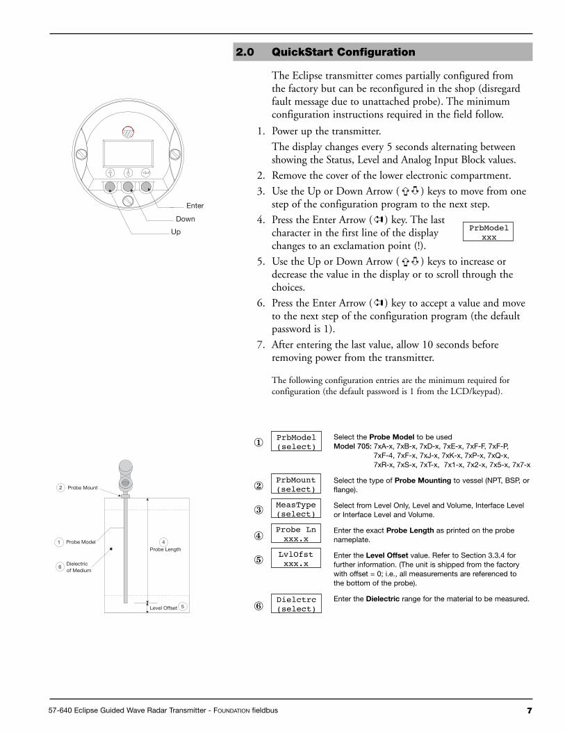
2.0 QuickStart Configuration
The Eclipse transmitter comes partially configured fromthe factory but can be reconfigured in the shop (disregardfault message due to unattached probe). The minimumconfiguration instructions required in the field follow.
1. Power up the transmitter.
The display changes every 5 seconds alternating betweenshowing the Status, Level and Analog Input Block values.
2. Remove the cover of the lower electronic compartment.
3. Use the Up or Down Arrow ( ) keys to move from onestep of the configuration program to the next step.
4. Press the Enter Arrow ( ) key. The lastcharacter in the first line of the displaychanges to an exclamation point (!).
5. Use the Up or Down Arrow ( ) keys to increase ordecrease the value in the display or to scroll through thechoices.
6. Press the Enter Arrow ( ) key to accept a value and moveto the next step of the configuration program (the defaultpassword is 1).
7. After entering the last value, allow 10 seconds beforeremoving power from the transmitter.
The following configuration entries are the minimum required forconfiguration (the default password is 1 from the LCD/keypad).
PrbModelxxx
PrbModel(select)
Probe Lnxxx.x
LvlOfstxxx.x
Dielctrc(select)
Select the Probe Model to be usedModel 705: 7xA-x, 7xB-x, 7xD-x, 7xE-x, 7xF-F, 7xF-P,
7xF-4, 7xF-x, 7xJ-x, 7xK-x, 7xP-x, 7xQ-x, 7xR-x, 7xS-x, 7xT-x, 7x1-x, 7x2-x, 7x5-x, 7x7-x
Select the type of Probe Mounting to vessel (NPT, BSP, orflange).
Select from Level Only, Level and Volume, Interface Levelor Interface Level and Volume.
Enter the exact Probe Length as printed on the probenameplate.
Enter the Level Offset value. Refer to Section 3.3.4 forfurther information. (The unit is shipped from the factorywith offset = 0; i.e., all measurements are referenced tothe bottom of the probe).
Enter the dielectric range for the material to be measured.Level Offset
Probe Length
Probe Mount
Probe Model
Dielectricof Medium
2
5
6
41
➪
➪
➪
➪
➪
➪
①
②
③
④
⑤
⑥
PrbMount(select)
Enter
Down
Up
MeasType(select)

8 57-640 Eclipse Guided Wave Radar Transmitter - FOUNDATION fieldbus
3.0 Function Blocks
3.1 Overview
The Enhanced Eclipse Model 705FF is a Guided Wave Radar(GWR) level transmitter with seven FOUNDATION fieldbus™
Function Blocks (one Resource Block, one TransducerBlock, four Analog Input Blocks, and one PID Block). Theidea of Function Blocks, which a user can customize for aparticular application, is a key concept of Fieldbus topology.Function Blocks consist of an algorithm, inputs and out-puts, and a user-defined name.
The TRANSDUCER block output is available to the net-work through the ANALOG INPUT blocks.
• The ANALOG INPUT blocks (AI) take the TRANSDUCERblock level or volume values and makes them available as ananalog value to other function blocks. The AI blocks havescaling conversion, filtering, and alarm functions.
3.1.1 Universal Fieldbus Block Parameters
The following are general descriptions of the parameterscommon to all blocks. Additional information for a givenparameter is described later in that specific block section.
ST_REV (static data revision): a read only parameter thatgives the revision level of the static data associated with theblock. This parameter will be incremented each time a staticparameter attribute value is written and is a vehicle fortracking changes in static parameter attributes.
TAG_DESC (tag descriptor): a user assigned parameterthat describes the intended application of any given block.
STRATEGY: a user assigned parameter that identifiesgroupings of blocks associated with a given network connec-tion or control scheme.
ALERT_KEY: a user assigned parameter which may be usedin sorting alarms or events generated by a block.
MODE_BLK: a structured parameter composed of theactual mode, the target mode, the permitted mode(s), andthe normal mode of operation of a block.
• The actual mode is set by the block during its execution toreflect the mode used during execution.
• The target mode may be set and monitored through themode parameter.

957-640 Eclipse Guided Wave Radar Transmitter - FOUNDATION fieldbus
• The permitted modes are listed for each block.
• The block must be in an automatic mode for normaloperation.
NOTE: The MODE_BLK target parameter must be OOS (out of service)to change configuration and calibration parameters in that func-tion block (when in OOS, the normal algorithm is no longer exe-cuted and any outstanding alarms are cleared).
All blocks must be in an operating mode for the device to oper-ate. This requires the Resource Block to be in “AUTO” and theTransducer Block to be in “AUTO” before the Function Blockscan be placed in a mode other than OOS (out of service).
BLOCK_ERR: a parameter that reflects the error status ofhardware or software components associated with, anddirectly affecting, the correct operation of a block.
NOTE: A BLOCK_ERR of “Simulation Active” in the Resource Blockdoes not mean simulation is active—it merely indicates that thesimulation (hardware) enabling jumper is present.
3.2 Resource Block
The RESOURCE block contains data specific to theEnhanced Model 705 transmitter, along with someinformation about the firmware.
NOTE: The Resource Block has no control function.
MODE_BLK: Must be in AUTO in order for the remain-ing blocks in the transmitter to operate.
NOTE: A Resource Block in “out of service” will stop all function blockexecution in the transmitter.
RS_STATE (Resource State): identifies the state of theRESOURCE block state machine. Under normal operatingconditions, it should be “On-Line.”
DD_RESOURCE: a string identifying the tag of theresource that contains the Device Description for this device.
MANUFAC_ID: contains Magnetrol International’sFOUNDATION fieldbus™ manufacturer’s ID number, which is0x000156.
DEV_TYPE: the model number of the Enhanced EclipseModel 705 transmitter (0x0001). It is used by interfacedevices to locate the Device Descriptor (DD) file for thisproduct.
DEV_REV: contains the firmware revision of the EnhancedEclipse Model 705 transmitter. It is used by interfacedevices to correctly select the associated DD.

10 57-640 Eclipse Guided Wave Radar Transmitter - FOUNDATION fieldbus
DD_REV: contains the revision of the DD associated withthe version of firmware in the Enhanced Eclipse Model 705transmitter. It is used by interface devices to correctly selectthe associated DD.
RESTART: Default and Processor selections are available.Default will reset the Model 705 to the established blockconfiguration.
NOTE: As RESTART DEFAULT will set most configuration parametersto their default values. Devices need to be reconfigured following activation of this function
FEATURES: a list of the features available in the transmit-ter. The Model 705 features include Reports, and Soft WriteLock.
FEATURES_SEL: allows the user to turn Features on or off.
CYCLE_TYPE: identifies the block execution methods thatare available.
CYCLE_SEL: allows the user to select the block executionmethod.
MIN_CYCLE_T: the time duration of the shortest cycleinterval. It puts a lower limit on the scheduling of theresource.
NV_CYCLE_T: the minimum time interval between copiesof non-volatile (NV) parameters to NV memory. NV mem-ory is only updated if there has been a significant change inthe dynamic value and the last value saved will be availablefor the restart procedure. A value of “0” means it will neverbe automatically copied. Entries made by human interfacedevices to NV parameters are copied to non-volatile memoryat the time of entry.
NOTE: After completing a large copy, allow several seconds beforeremoving power from the Eclipse Model 705 transmitter toensure that all data has been saved.
FREE_SPACE: shows the amount of available memory forfurther configuration. The value is zero percent in a pre-configured device.
FREE_TIME: the amount of the block processing time thatis free to process additional blocks.
SHED_RCAS: the time duration at which to give up com-puter writes to function block RCas locations. Shed fromRCas will never happen when SHED_RCAS = 0.
SHED_ROUT: the time duration at which to give up com-puter writes to function block ROut locations. Shed fromROut will never happen when SHED_ROUT = 0.

1157-640 Eclipse Guided Wave Radar Transmitter - FOUNDATION fieldbus
FAULT_STATE, SET_FSTATE, CLR_FSTATE: these onlyapply to output function blocks. (The Model 705 has nooutput function blocks).
MAX_NOTIFY: the maximum number of alert reports thatthe transmitter can send without getting a confirmation.
The user can set the number low, to control alert flooding,by adjusting the LIM_NOTIFY parameter value.
LIM_NOTIFY: the maximum numbers of unconfirmedalert notify messages allowed. No alerts are reported if setto zero.
CONFIRM_TIME: the time that the transmitter will waitfor confirmation of receipt of a report before trying again.Retry will not occur if CONFIRM_TIME = 0.
WRITE_LOCK:When set to LOCKED, will prevent anyexternal change to the static or non-volatile data base in theFunction Block Application of the transmitter. Block con-nections and calculation results will proceed normally, butthe configuration will be locked.
UPDATE_EVT (Update Event): is an alert generated by awrite to the static data in the block.
BLOCK_ALM (Block Alarm): is used for configuration,hardware, connection, or system problems in the block. Thecause of any specific alert is entered in the subcode field.The first alert to become active will set the Active status inthe Status attribute. As soon as the Unreported status iscleared by the alert reporting task, another block alert maybe reported without clearing the Active status, if the sub-code has changed.
ALARM_SUM (Alarm Summary): contains the currentalert status, the unacknowledged states, the unreportedstates, and the disabled states of the alarms associated withthe block.
ACK_OPTION (Acknowledge Option): selects whetheralarms associated with the block will be automaticallyacknowledged.
WRITE_PRI (Write Priority): the priority of the alarmgenerated by clearing the write lock.
WRITE ALM (Write Alarm): the alert generated if thewrite lock parameter is cleared.
ITK_VER (ITK Version): contains the version of theInteroperability Test Kit (ITK) used by the FieldbusFoundation during their interoperability testing.

12 57-640 Eclipse Guided Wave Radar Transmitter - FOUNDATION fieldbus
3.3 Transducer Block
The TRANSDUCER block is a custom block containingparameters that support the Enhanced Eclipse Model 705level transmitter. It contains the GWR probe configuration,diagnostics, and calibration data, and outputs level withstatus information.
The TRANSDUCER block parameters are grouped in auseful configuration. There are both read-only parametersand read-write parameters within the TRANSDUCER block.
• The read-only parameters report the block status andoperation modes.
• The read-write parameters affect the function block basicoperation, level transmitter operation, and calibration.
the transducer Block will automatically be changed to
“Out of Service” when the local interface (keypad) is used
to change a parameter online. the transducer Block must
be placed back in service from the Host system.
3.3.1 transducer Block Parameters
The first six parameters in the TRANSDUCER block arethe universal parameters discussed in section 3.1.1. Theuniversal parameters are followed by these additionalrequired parameters:
UPDATE_EVT (Update Event): an alert generated by awrite to the static data in the TRANSDUCER block.
Another important parameter found later in the TRANS-DUCER block list is DEVICE_STATUS, which displaysthe status of the device. If more than one message exists,then the messages are displayed in priority order.
If DEVICE_STATUS indicates a problem, refer toSection 6.1, Troubleshooting (those parameters which areshaded are password-protected).
For a complete list of transducer Block Parameters, refer
to table in the appendix.
3.3.2 Password Parameters
To change a parameter at the local user interface, a valuematching the user password must be entered (Default=1). Ifthe user password is entered, the instrument is in the usermode. After 5 minutes with no keypad activity, the enteredpassword expires.
Factory password is for use by trained factory personnel only.
From the Host system network, the instrument alwaysbehaves as if it is in the user mode by default. In otherwords, it is not necessary to enter the user password in orderto write parameters from the Host system.

1357-640 Eclipse Guided Wave Radar Transmitter - FOUNDATION fieldbus
3.3.3 Eclipse Model 705 Configuration Parameters
This set of parameters within the Transducer Block is impor-tant and required to configure every Eclipse Model 705transmitter.
PROBE_MODEL: Select the choice that corresponds to thefirst four digits of the model number of the probe. An “x”in the selection means that character is variable (the probemodel number is shown on the nameplates attached to boththe transmitter and probe). For example, 7xA-x should bechosen for probe models beginning with 7EA or 7MA.
PROBE_MOUNT: Select the type of mounting on theprobe. The choices are NPT, BSP, and Flange.
MEASUREMENT_TYPE: Select from LEVEL ONLY,LEVEL AND VOLUME, INTERFACE, or INTERFACEAND VOLUME.
PROBE_LENGTH: Enter the exact length of the probe.The probe length is shown as the last three digits of theprobe model number printed on the nameplates attached tothe transmitter and probe. PROBE_LENGTH is shown inSENSOR_UNITs.
LEVEL_OFFSET: Enter the distance from the probe tip tothe desired 0% reference in PROBE_UNITs. The accept-able range is from -300 inches to 600 inches. Refer toSection 3.3.4 for additional information.
DIELECTRIC_RANGE: Select from 10–100, 3–10, 1.7–3.0, or 1.7–1.4
NOTE: All dielectric ranges are not available with all probes.
If an unsupported dielectric range is selected, the transmitterwill give a negative response and the value displayed willrevert to its previous value.
THRESHOLD: The threshold can be set as either FIXEDor CFD. This parameter should be set to FIXED in thoseapplications measuring total level having a lower dielectricmaterial over a higher dielectric material. (A typical examplefor FIXED Threshold is a hydrocarbon application havingwater bottoms.)
Offset
Probe Length
Probe Mount
0% Set Point
Probe Model
Dielectricof Medium
100% Set Point
14 57-640 Eclipse Guided Wave Radar Transmitter - FOUNDATION fieldbus
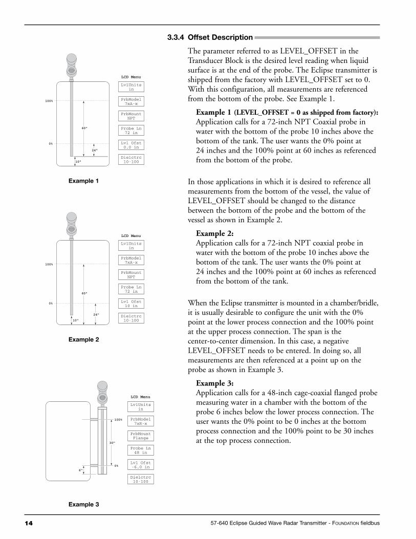
3.3.4 Offset description
The parameter referred to as LEVEL_OFFSET in theTransducer Block is the desired level reading when liquidsurface is at the end of the probe. The Eclipse transmitter isshipped from the factory with LEVEL_OFFSET set to 0.With this configuration, all measurements are referencedfrom the bottom of the probe. See Example 1.
Example 1 (LEVEL_OFFSET = 0 as shipped from factory): Application calls for a 72-inch NPT Coaxial probe inwater with the bottom of the probe 10 inches above thebottom of the tank. The user wants the 0% point at24 inches and the 100% point at 60 inches as referencedfrom the bottom of the probe.
In those applications in which it is desired to reference allmeasurements from the bottom of the vessel, the value ofLEVEL_OFFSET should be changed to the distancebetween the bottom of the probe and the bottom of thevessel as shown in Example 2.
Example 2:Application calls for a 72-inch NPT coaxial probe inwater with the bottom of the probe 10 inches above thebottom of the tank. The user wants the 0% point at24 inches and the 100% point at 60 inches as referencedfrom the bottom of the tank.
When the Eclipse transmitter is mounted in a chamber/bridle,it is usually desirable to configure the unit with the 0%point at the lower process connection and the 100% pointat the upper process connection. The span is thecenter-to-center dimension. In this case, a negativeLEVEL_OFFSET needs to be entered. In doing so, allmeasurements are then referenced at a point up on theprobe as shown in Example 3.
Example 3:Application calls for a 48-inch cage-coaxial flanged probemeasuring water in a chamber with the bottom of theprobe 6 inches below the lower process connection. Theuser wants the 0% point to be 0 inches at the bottomprocess connection and the 100% point to be 30 inchesat the top process connection.
10"
60"
100%
LCD Menu
0%
24"
PrbModel7xA-x
PrbMountNPT
LvlUnitsin
Probe Ln72 in
Lvl Ofst0.0 in
Dielctrc10-100
Example 1
10"
60"
100%
0%
24"
PrbModel7xA-x
PrbMountNPT
LvlUnitsin
Probe Ln72 in
Lvl Ofst10 in
Dielctrc10-100
LCD Menu
Example 2
6"
30"
0%
100% PrbModel7xR-x
PrbMountFlange
LvlUnitsin
Probe Ln48 in
Lvl Ofst-6.0 in
Dielctrc10-100
LCD Menu
Example 3
1557-640 Eclipse Guided Wave Radar Transmitter - FOUNDATION fieldbus
3.4 User-Calibration Parameters
One of the main advantages of the Enhanced Eclipse Model705 GWR transmitter is that the device does not need to becalibrated in the field. Every Enhanced Eclipse Model 705transmitter is shipped precisely calibrated from the factory.
On the other hand, part of the advantage ofFOUNDATION fieldbus™ is to provide the ability to monitorchanges and make adjustments to a transmitter. TheFieldbus™ concept allows a user to make calibration adjust-ments if deemed necessary.
NOTE: The original factory calibration settings are restored when a newprobe length value is assigned.
It is highly recommended that factory calibration be used
for optimum performance.
Contact the factory for information on how to perform aUser Calibration.
3.4.1 Factory Parameters
The factory-adjustable calibrated parameters are WINDOW,CONVERSION_FACTOR, and SCALE_OFFSET.
WINDOW is used to adjust for the variations in the analogsection of the Eclipse TDR measurement engine. CON-VERSION_FACTOR and SCALE_OFFSET are the mainfactory calibration settings.
The following parameters are used for either troubleshoot-ing or are parameters adjusted at the factory. They shouldnever be changed in the field.
WINDOW: determines the amount of delay between thegeneration of the transmitted signal pulse and the start ofthe measurement cycle.
FID_TICKS: a measure of the time to the fiducial (refer-ence) pulse.
FID_TICKS_SPREAD: provides an indication of thestability of the FID_TICKS measurement.
LEVEL_TICKS: a measure of the time to the level of theproduct being measured.
LEVEL_TICKS_SPREAD: provides an indication of thestability of the LEVEL_TICKS measurement.
CONVERSION_FACTOR: the slope of the factory-setcalibration line.
SCALE_OFFSET: the intercept of the calibration line.

16 57-640 Eclipse Guided Wave Radar Transmitter - FOUNDATION fieldbus
3.4.2 Firmware Version
The last parameter in the TRANSDUCER block gives thefirmware version of the transmitter.
FIRMWARE_VERSION: displays the version of thefirmware.
NOTE: The user should compare the DD file and revision number of thedevice with the HOST system to ensure they are at the samerevision level.
Refer to the table in section 1.3.1.
3.5 Analog Input Block
The ANALOG INPUT (AI) block takes the Eclipse Model705 input data, selected by channel number, and makes itavailable to other function blocks at its output:
3.5.1 aI Block Parameters
PV: Either the primary analog value for use in executing thefunction, or a process value associated with it.
OUT: The primary analog value calculated as a result ofexecuting the function block.
SIMULATE: Allows the transducer analog input or outputto the block to be manually supplied when simulate isenabled. When simulate is disabled, the simulate value andstatus track the actual value and status
XD_SCALE: The high and low scale values, engineeringunits code, and number of digits to the right of the decimalpoint used with the value obtained from the transducer fora specified channel.
OUT_SCALE: The high and low scale values, engineeringunits code, and number of digits to the right of the decimalpoint to be used in displaying the OUT parameter.
GRANT_DENY: Options for controlling access of hostcomputers and local control panels to operating, tuning,and alarm parameters of the block.
IO_OPTS: Option which the user may select to alter inputand output block processing.
STATUS_OPTS: Options which the user may select in theblock processing of status.
Offset
Probe Length
XD
_SC
ALE
"EU
@10
0%" (
in. c
m, f
t. m
)
XD
_SC
ALE
"EU
@0%
" (in
. cm
, ft.
m)
100%
0%
default Scaling
Channel Process Value
1 Level
2 Volume
3 Interface
4 Interface Volume

1757-640 Eclipse Guided Wave Radar Transmitter - FOUNDATION fieldbus
CHANNEL: The number of the logical hardware channelthat is connected to this I/O block. This informationdefines the transducer to be used going to or from thephysical world.
L_TYPE: Determines if the values passed by the transducerblock to the AI block may be used directly (Direct) or if thevalue is in different units and must be converted linearly(Indirect), or with square root (Ind Sqr Root), using theinput range defined for the transducer and the associatedoutput range.
LOW_CUT: Limit used in square root processing.
PV_FTIME: Time constant of a single exponential filter forthe PV, in seconds.
FIELD_VAL: Raw value of the field device in % of PVrange, with a status reflecting the Transducer condition,before signal characterization (L_TYPE) or filtering(PV_FTIME).
UPDATE_EVT: This alert is generated by any change tothe static data.
BLOCK_ALM: The block alarm is used for all configuration,hardware, connection failure or system problems in the block.
ALARM_SUM: The current alert status, unacknowledgedstates, unreported states, and disabled states of the alarmsassociated with the function block.
ACK_OPTION: Selection of whether alarms associatedwith the function block will be automatically acknowl-edged.
ALARM_HYS: Amount the PV must return within thealarm limits before the alarm condition clears. Alarm hys-teresis expressed as a percent of the span of the PV.
HI_HI_PRI: Priority of the high high alarm.
HI_HI_LIM: The setting for high high alarm inengineering units.
HI_PRI: Priority of the high alarm.
HI_LIM: The setting for high alarm in engineering units
LO_PRI: Priority of the low alarm.
LO_LIM: The setting for low alarm in engineering units.
LO_LO_PRI: Priority of the low low alarm.
LO_LO_LIM: The setting for low low alarm in engineeringunits.
HI_HI_ALM: The status for high high alarm and itsassociated time stamp.
18 57-640 Eclipse Guided Wave Radar Transmitter - FOUNDATION fieldbus
HI_ALM: Status for high alarm and associated time stamp.
LO_ALM: Status for low alarm and associated time stamp.
LO_LO_ALM: The status for low low alarm and itsassociated time stamp.
The TRANSDUCER and AI block’s MODE_BLK parame-ter must be set to AUTO to pass the PV Value through theAI to the network.
Transducer scaling, called XD_SCALE, is applied to thePV from the CHANNEL to produce the FIELD_VAL inpercent. Valid XD_SCALE engineering units is limitedto the five allowable codes of meters (m), centimeters (cm),feet (ft), inches (in), and percent (%) for the Level channels,or gallons, liters, % for the volume channels.
The AI blocks can have a BLOCK_ERR when:
1. Channel is not set correctly.
2. XD_SCALE does not have suitable engineering units or hasrange incompatibility.
3. SIMULATE parameter is active
4. AI block MODE is O/S (out of service).
NOTE: This can be caused by the Resource Block being OOS or the AIBlock not scheduled for execution.
5. L-TYPE not set or set to Direct with improperOUT_SCALE.
The AI block uses the STATUS_OPTS setting and theTRANSDUCER PV LIMIT value to modify the AI PVand OUT QUALITY.
Damping Filter is a feature of the AI block. The PV_FTIMEparameter is a time constant of a single exponential filter forthe PV, in seconds. This parameter can be used to dampenout fluctuation in level due to excessive turbulence.
The AI block has multiple ALARM functions that monitorthe OUT parameter for out of bound conditions.
3.5.2 Local display of analog Input transducer Block Output
The Model 705 3x FOUNDATION fieldbus™ Device Revision2 transmitter incorporates a feature that allows the device’sAnalog Input [AI] block Out values to be displayed on thelocal LCD.
NOTE: There are many reasons that AI block Out values can deviatefrom the measurement value originating in the Transducerblock, and because the keypad and local display will only pro-vide access to Transducer block parameters, there is no way toexplore or change the other fieldbus configuration items affect-ing the AI block output using the keypad and LCD.

1957-640 Eclipse Guided Wave Radar Transmitter - FOUNDATION fieldbus
These screens should only be considered as measured valueindicators for configured transmitters.
• The screens are not used for commissioning or diagnostic /troubleshooting purposes.
• Prior to full fieldbus configuration (transmitter assigned a per-manent address, AI block(s) configured and scheduled for exe-cution, etc.), the value displayed will not reflect the transducermeasurement. (Pre-configuration values will typically be 0).
3.5.2.1 AI Out Display Screens
The Analog Input Out values will be conditionally dis-played as part of the “rotating” home menu screens.
The screens will be formatted as shown where # in the titleis the number of the AI block (1, 2, 3, or 4) and mmm isone of: “Lvl”, “Vol”, “Ifc”, “IfV”, “---” depending on thevalue of the associated AI block’s Channel parameter.
• For example, “AI1Lvl” would be the most commonly usedAI Out screen.
• “AI2---” would be displayed when the channel value is 0[uninitialized] for AI block 2.
The Out value will be displayed subject to limitations nec-essary for a 6-character display [999999 > Value > -99999].
Representative examples are shown below:
Because the Model 705 transmitter has four Analog Inputblocks any or all of which may be used in particular applica-tions, a Transducer block parameter controls which AI blockOut values will be displayed.
The fieldbus presentation of this parameter will be similarto that shown at left (host system dependent).
Any or all (or none) of the AI block Out values can beselected for display on the LCD.
The local LCD version of this parameter is shown different-ly due to the limitations of the LCD:
LCD label: “AI Disp ”
The default value of the Local AI Display parameter will besuch that AI 1 Out is selected.
*AI#mmm*######uu
*AI1Vol*999999 L
*AI3Ifc*0.0 %
*AI1Lvl*99.5 cm
Analog Input Out Display
Local AI Display AI1 OutAI2 OutAI3 OutAI4 Out
NoneAI1AI2
AI1+AI2AI3
AI1+AI3AI2+AI3AIs1,2,3
AI4AI1+AI4AI2+AI4AIs1,2,4AI3+AI4AIs1,3,4AIs2,3,4All AIs
Analog Input Out Values
To Be Displayed
Out Value
Out Scale unitsabbreviation
AI block channelmeasurement type
Analog Input block #

20 57-640 Eclipse Guided Wave Radar Transmitter - FOUNDATION fieldbus
3.6 PID Block
The PID Function Block contains the logic necessary to per-form Proportional/Integral/Derivative (PID) control. The blockprovides filtering, set point limits and rate limits, feedforwardsupport, output limits, error alarms, and mode shedding.
Although most other function blocks perform functions specificto the associated device, the PID block may reside in any deviceon the network. This includes a valve, a transmitter, or the hostitself.
The Enhanced Model 705 3X PID Block implementation fol-lows the specifications documented by the Fieldbus Foundation.
3.6.1 PId Block Parameters
ACK_OPTION: Used to set auto acknowledgement ofalarms.
ALARM_HYS: The amount the alarm value must return tobefore the associated active alarm condition clears.
ALARM_SUM: The summary alarm is used for all processalarms in the block.
ALERT_KEY: The identification number of the plant unit.
ALG_TYPE: Selects filtering algorithm as Backward orBi-linear.
BAL_TIME: The specified time for the internal workingvalue of bias to return to the operator set bias.
BKCAL_IN: The analog input value and status for anotherblocks BKCAL_OUT output.
BKCAL_HYS: The amount the output must change awayfrom its output limit before the limit status is turned off,expressed as a percent of the span of the output.
BKCAL_OUT: The value and status required by theBKCAL_IN input for another block.
BLOCK_ALM: Used for all configuration, hardware, con-nection failure, or system problems in the block.
BLOCK_ERR: Reflects the error status associated with thehardware or software components associated with a block.
BYPASS: Used to override the calculation of the block.
CAS_IN: The remote setpoint value from another block.
CONTROL_OPTS: Allows one to specify control strategyoptions.
DV_HI_ALM: The DV HI alarm data.
DV_HI_LIM: The setting for the alarm limit used todetect the deviation high alarm condition.
DV_HI_PRI: The priority of the deviation high alarm.
DV_LO_ALM: The DV LO alarm data.

2157-640 Eclipse Guided Wave Radar Transmitter - FOUNDATION fieldbus
3.6.1 PId Block Parameters (cont.)
DV_LO_LIM: The setting for the alarm limit used todetect the deviation low alarm condition.
DV_LO_PRI: The priority of the deviation low alarm.
FF_GAIN: The feedforward gain value.
FF_SCALE: The high and low scale values associated withFF_VAL.
FF_VAL: The feedforward control input value and status.
GAIN: The proportional gain value. This value cannotequal zero.
GRANT_DENY: Options for controlling access of hostcomputers to alarm parameters of the block.
HI_ALM: The HI alarm data
HI_HI_ALM: The HI HI alarm data
HI_HI_LIM: The setting for the alarm limit used to detectthe HI HI alarm condition.
HI_HI_PRI: The priority of the HI HI Alarm.
HI_LIM: The setting for the alarm limit used to detect theHI alarm condition.
HI_PRI: The priority of the HI alarm.
IN: The connection for the PV input from another block.
LO_ALM: The LO alarm data.
LO_LIM: The setting for the alarm limit used t detect theLO alarm condition.
LO_LO_ALM: The LO LO alarm data.
LO_LO_PRI: The priority of the LO LO alarm.
LO_PRI: The priority of the LO alarm.
MATH_FORM: Selects equation form (series or standard).
MODE_BLK: The actual, target, permitted, and normalmodes of the block.
OUT: The block input value and status.
OUT_HI_LIM: The maximum output value allowed.
OUT_LO_LIM: The minimum output value allowed.
OUT_SCALE: The high and low scale values associatedwith OUT.
PV: The process variable use in block execution.
PV_FTIME: The time constant of the first order PV filter.
PV_SCALE: The high and low scale values associated with PV.

22 57-640 Eclipse Guided Wave Radar Transmitter - FOUNDATION fieldbus
3.6.1 PId Block Parameters (cont.)
RATE: The derivative action time constant.
RCAS_IN: Target setpoint and status that is provided by asupervisory host.
RCAS_OUT: Block setpoint and status that is provided to asupervisory host.
RESET: The integral action time constant.
ROUT_IN: Block output that is provided by a supervisoryhost.
ROUT_OUT: Block output that is provided to a superviso-ry host.
SHED_OPT: Defines action to be taken on remote controldevice timeout.
SP: The target block setpoint value.
SP_HI_LIM: The highest SP value allowed.
SP_LO_LIM: The lowest SP value allowed.
SP_RATE_DN: Ramp rate for downward SP changes.
SP_RATE_UP: Ramp rate for upward SP changes.
STATUS_OPTS: Allows one to select options for statushandling and processing.
STRATEGY: Can be used to identify grouping of blocks.
ST_REV: The revision level of the static data associatedwith the function block.
TAG_DESC: The user description of the intended applica-tion of the block.
TRK_IN_D: Discrete input that initiates external tracking.
TRK_SCALE: The high and low scale values associatedwith TRK_VAL.
TRK_VAL: The value applied to OUT in LO mode.
UPDATE_EVT: This alert is generated by any changes tothe static data.
2357-640 Eclipse Guided Wave Radar Transmitter - FOUNDATION fieldbus
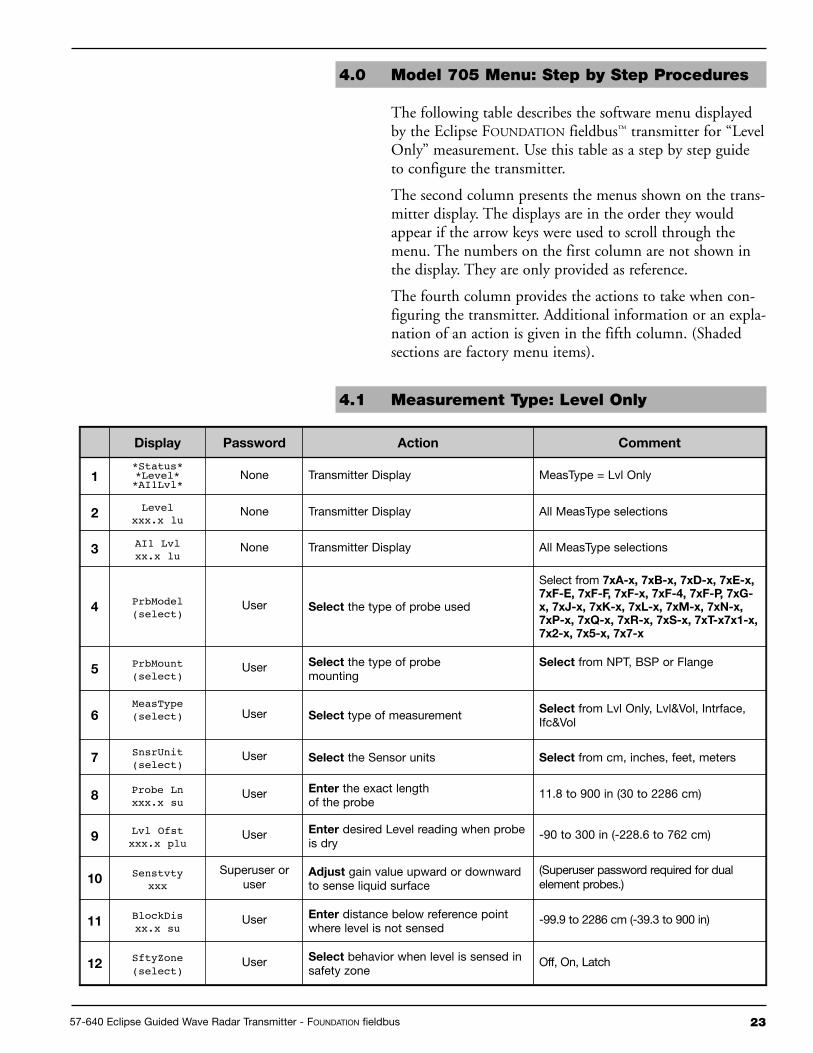
4.0 Model 705 Menu: Step by Step Procedures
The following table describes the software menu displayedby the Eclipse FOUNDATION fieldbus™ transmitter for “LevelOnly” measurement. Use this table as a step by step guideto configure the transmitter.
The second column presents the menus shown on the trans-mitter display. The displays are in the order they wouldappear if the arrow keys were used to scroll through themenu. The numbers on the first column are not shown inthe display. They are only provided as reference.
The fourth column provides the actions to take when con-figuring the transmitter. Additional information or an expla-nation of an action is given in the fifth column. (Shadedsections are factory menu items).
4.1 Measurement Type: Level Only
display Password action Comment
1*Status**Level**AI1Lvl*
None Transmitter Display MeasType = Lvl Only
2Level
xxx.x luNone Transmitter Display All MeasType selections
3AI1 Lvlxx.x lu
None Transmitter Display All MeasType selections
4PrbModel(select)
User Select the type of probe used
Select from 7xa-x, 7xB-x, 7xd-x, 7xE-x,7xF-E, 7xF-F, 7xF-x, 7xF-4, 7xF-P, 7xG-x, 7xJ-x, 7xK-x, 7xL-x, 7xM-x, 7xn-x,7xP-x, 7xQ-x, 7xR-x, 7xS-x, 7xt-x7x1-x,7x2-x, 7x5-x, 7x7-x
5PrbMount(select)
User Select the type of probemounting
Select from NPT, BSP or Flange
6MeasType(select) User Select type of measurement Select from Lvl Only, Lvl&Vol, Intrface,
Ifc&Vol
7SnsrUnit(select)
User Select the Sensor units Select from cm, inches, feet, meters
8Probe Lnxxx.x su
User Enter the exact lengthof the probe
11.8 to 900 in (30 to 2286 cm)
9Lvl Ofstxxx.x plu
User Enter desired Level reading when probeis dry
-90 to 300 in (-228.6 to 762 cm)
10Senstvty
xxxSuperuser or
useradjust gain value upward or downwardto sense liquid surface
(Superuser password required for dualelement probes.)
11BlockDisxx.x su
User Enter distance below reference pointwhere level is not sensed
-99.9 to 2286 cm (-39.3 to 900 in)
12SftyZone(select)
User Select behavior when level is sensed insafety zone
Off, On, Latch

24 57-640 Eclipse Guided Wave Radar Transmitter - FOUNDATION fieldbus
display Password action Comment
13SZHeightxx.x su User
Enter distance below BlockDis whereSZ Fault will be asserted
5.1 to 2286 cm (2 to 900 in)
14SZ LatchReset User Press Enter to clear a Safety Zone latch
15Threshld(select) User Select from CFD, Fixed
For interface, refers to threshold forupper level pulse
16Trim Lvlxx.x su
Superuser oruser
Enter value to adjust Level reading-20.0 inches <= Lvl Trim <= +20.0 inches(Superuser password required if negativefiducial.)
17 AI Disp User Transmitter Display AI Block Display
18LvlTicksxxxxx User Diagnostic Display Time of flight from fiducial to level signal
19New Pass
xxx User Enter new password (0-255)Displays encrypted value of presentpassword
20Language(select) User
Select from English, Spanish, French,German
Language choice forLCD display
21Mdl705FFVer 3.xx None Transmitter Display
Product identificationFirmware version
22DispFact(select) None
Select Yes to display factory parametermenus
23 History Status NoneDiagnostic Display to view present statusand recent exceptions
24Run Timexxxx.x h None
Diagnostic Display showing elapsedtime since power on
Cleared to zero with History Reset
25HistoryReset Superuser
Press Enter and select yes to clearhistory
Reset History Data
26HF CableSelect Superuser
Select length of remoteextension cable
Select from integral, 3-foot, 12-foot
27FidTicks
xxxx None Diagnostic DisplayTime of flight from start oframp to fiducial
28Fid Sprd
xxx None Diagnostic Display Spread in fiducial ticks readings
29Fid Type(select) Superuser Superuser parameter
Select from Positive, Negative.Selection only allowed for some probes,fixed for others
30Fid Gain
xxx Superuser Superuser parameter
31Windowxxx
Factory Factory Parameter Calibration parameter
32Conv Fct
xxxx Factory Factory Parameter Calibration parameter
33Scl Ofst
xxxFactory Factory Parameter Calibration parameter

2557-640 Eclipse Guided Wave Radar Transmitter - FOUNDATION fieldbus
display Password action Comment
34Neg Ampl
xxx Superuser Superuser parameter Diagnostic parameter
35Pos Ampl
xxx Superuser Superuser parameter Diagnostic parameter
36Signalxxx None Diagnostic Display
Indication of levelsignal amplitude
37 Compsate Superuser Superuser ParameterSelect from None,Manual, Auto
38DrateFct
xxxx None Diagnostic DisplayCompsate = Auto, velocityderating factor
39TargAmpl
xxxx None Diagnostic DisplayCompsate = Auto, targetnegative threshold amplitude
40Targ Tks
xxxx None Diagnostic DisplayCompsate = Auto, measured time of flightfrom fiducial to target
41Targ Cal
xxxx Superuser Diagnostic DisplayCompsate = Auto, calibrated time of flightfrom fiducial to target in room temperatureair
42OperMode(select) Superuser Superuser parameter
Compsate = Auto, select from Run, Cal,Off
437xK Corr
xxx Superuser Superuser parameterProbe Model = 7xK, Distance in mm fromfiducial to userreference point
44Snsr Valxxx.x su None
Distance to the target relative to the sensorreference point.
45CalPtLoxxx.x su Superuser
The lower calibrated point of Sensor Value.It refers to PrLvl Lo.
In Sensor Units (Do Not Adjust)
46CalPtHixxx.x su Superuser
The higher calibrated point of SensorValue. It refers to PrLvl Hi.
In Sensor Units (Do Not Adjust)
47ProbeLvlxxx.x plu None
Level on the probe relative to the end ofthe probe.
48PrLvl Loxxx.x plu Superuser Value of PrLvl at SnrCalLo. In Probe Level Units
49PrLvl Hixxx.x plu Superuser Value of PrLvl at SnrCalHi. In Probe Level Units
50ElecTempxxx C None Diagnostic Display Present temperature in electronics
compartment (degrees Celsius)
51Max Tempxxx C Superuser Diagnostic Display Maximum electronics
temperature recorded
52Min Tempxxx C Superuser Diagnostic Display Minimum electronics
temperature recorded
53SZ Hystxx.x su Superuser Superuser Parameter Safety Zone hysteresis height

26 57-640 Eclipse Guided Wave Radar Transmitter - FOUNDATION fieldbus
5.0 Diagnostic Parameters
The Eclipse Model 705 measurement engine runs through aseries of self-tests and will detect and report faulty operation. The TRANSDUCER BLOCK displays these faults in theDEVICE_STATUS parameter. Refer to Section 6.1.2 formore information on specific faults and warnings.
BLOCK_ERROR is not used except for indicating Out ofService (OOS).
When the Model 705 transmitter is initially powered on, themeasurement engine does not have enough valid measure-ment cycles to make a decision about the output level. Forthe first few seconds after power is applied, theLEVEL_STATUS/QUALITY is “Uncertain,” theSUB_STATUS is “Initial value,” and the LIMIT attribute is“Constant.”
When the Model 705 is operating properly, theLEVEL_STATUS/QUALITY is shown as “GOOD,” andthe SUB_STATUS is “Non-Specific.”
While changing the transmitter operational parameters usingthe local display or through the system configuration tool (withthe MODE_BLK in OOS), the output might be inaccuratebecause of the changing parameters. When the device is set toOOS, the TRANSDUCER BLOCK will still output level butthe QUALITY will be shown as “Bad” and the SUB_STATUSis “Out of Service.”
When the Enhanced Model 705 measurement cycle fails tofind a valid output level, the transmitter maintains the lastgood value as the output and flags the failure. The LIMITattribute is the same as the last good measurement.
When the Enhanced Model 705 detects a level above thehighest measurement point of the probe the operationalmode is shown as “May Be Flooded.” This is due to the factthat, since the actual level location above the top of someprobes is not known, the output may not be accurate.
The Model 705 operational mode is DRY_PROBE whenthe level is below the end of the probe. Again, the outputmay not be accurate, since the location of the level below theend of the probe is not known. The TRANSDUCERBLOCK output is calculated as LEVEL_OFFSET.
When in the dry probe condition, the Model 705 comparesthe measured length of the probe to the value entered intothe PROBE_LENGTH parameter. If the measured valuedoes not match PROBE_LENGTH, a fault is reported. TheQUALITY will be shown as “Bad,” and the SUB_STATUSis “Configuration error.”

2757-640 Eclipse Guided Wave Radar Transmitter - FOUNDATION fieldbus
If the Model 705 fails to find a measurable level, either dueto an actual loss of a level signal or the loss of a properFiducial (reference) signal, the TRANSDUCER BLOCKmaintains the last good value as the output and flags the fail-ure. The QUALITY is “Bad,” the SUB_STATUS is “Sensorfailure” for no level (or “Device failure” for loss of theFiducial), and the LIMIT attribute is “Constant.”
Refer to Section 6.1.2 for additional information.
5.1 Simulation Feature
The Eclipse Model 705 with FOUNDATION fieldbus™ sup-ports the Simulate feature in the Analog Input block. TheSimulate feature is typically used to exercise the operation ofan AI block by simulating a TRANSDUCER block input.
This feature can not be activated without the placement of ahardware jumper. This jumper is installed as standard onthe Eclipse Model 705, and is placed in an inconvenientlocation to avoid inadvertent disabling of this feature.
NOTE: A BLOCK_ERR of “Simulation Active” in the Resource Blockdoes not mean simulation is active—it merely indicates that thesimulation (hardware) enabling jumper is present.
Contact the factory for instructions on how to remove thisjumper and, if necessary, permanently disable the Simulatefeature.
28 57-640 Eclipse Guided Wave Radar Transmitter - FOUNDATION fieldbus
LEVEL and AI OUTPUT values Basic configuration data is Reconfigure the Probe Model and/or Probeare inaccurate. questionable. Mount, Probe Length or Level Offset.
1) Ensure the Level is accurate.2) Verify EU_0% and EU_100% values.
Interface level has significant emulsion. Examine process to reduce/eliminateemulsion layer.
LEVEL readings are repeatable but Configuration data does not Ensure proper Probe Model and probe length.consistently high or low from actual accurately match probe lengthby a fixed amount. or tank height. Adjust trim level value by the amount of
noted inaccuracy.
LEVEL and AI OUTPUT values Turbulence Increase the AI Block process value filterfluctuate. time until the readings stabilize.
High Frequency connection Check Fid Spread (should be stable within±10 counts).
LEVEL and AI OUTPUT values Lower dielectric material over higher Select Fixed Threshold option.all reading low vs. actual. dielectric material, e.g., oil over water
Coating, clumping or buildup on probe These may be expected inaccuracies dueto affect on pulse propagation.
Dense, water based foam These may be expected inaccuracies dueto affect on pulse propagation.
Level Reading on Display is stuck at Software believes probe is flooded Check actual level. If probe is not flooded,full scale. (level near very top of probe). Check for buildup or obstructions near top
of probe. Select higher dielectric range.Check for condensation in probeconnection. Add Blocking Distance.
LEVEL and AI OUTPUT values Possible configuration issue 1) Increase Blocking Distancevalues all at maximum level. with single rod probe 2) Increase Dielectric Range
LEVEL and AI OUTPUT values Possible obstruction in tank 1) Increase Dielectric Range untilreading high vs. actual. affecting single rod probe obstruction is ignored
2) Relocate probe away from obstruction
LEVEL value reading high when Transmitter loose or disconnected Ensure transmitter connected securelyshould be zero. from probe to probe.
Symptom Problem Solution
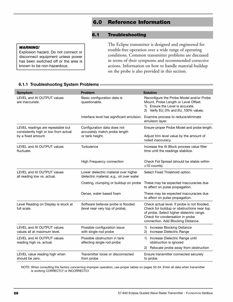
6.1.1 troubleshooting System Problems
NOTE: When consulting the factory concerning improper operation, use proper tables on pages 33-34. Enter all data when transmitteris working CORRECTLY or INCORRECTLY.
6.0 Reference Information
6.1 Troubleshooting
The Eclipse transmitter is designed and engineered fortrouble-free operation over a wide range of operatingconditions. Common transmitter problems are discussedin terms of their symptoms and recommended correctiveactions. Information on how to handle material buildupon the probe is also provided in this section.
WARNING!Explosion hazard. Do not connect ordisconnect equipment unless powerhas been switched off or the area isknown to be non-hazardous.
2957-640 Eclipse Guided Wave Radar Transmitter - FOUNDATION fieldbus
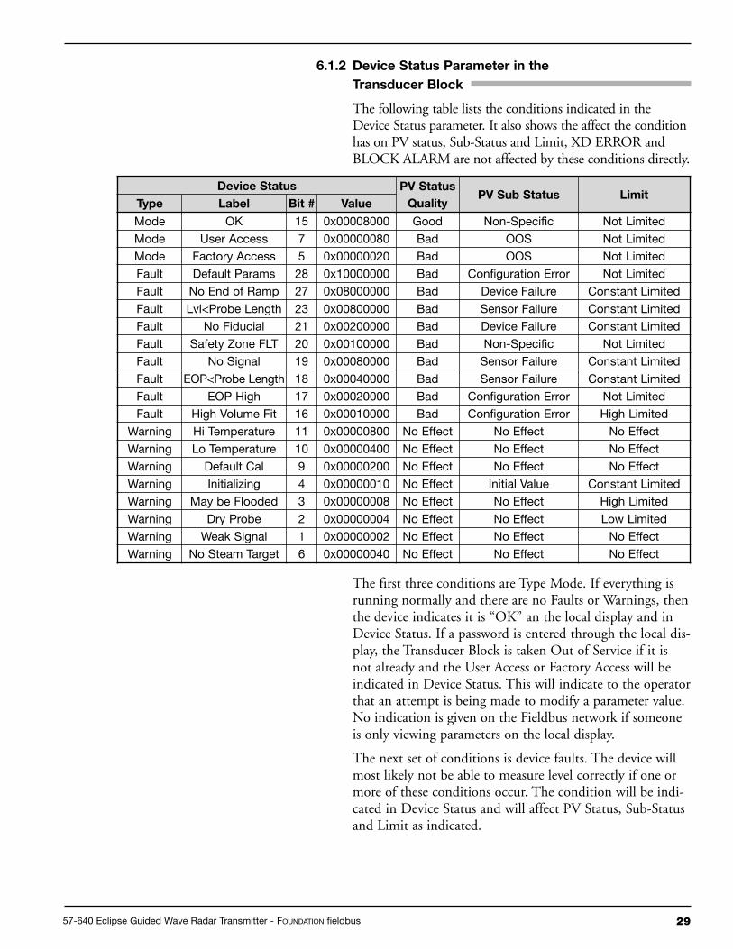
6.1.2 device Status Parameter in the
transducer Block
The following table lists the conditions indicated in theDevice Status parameter. It also shows the affect the conditionhas on PV status, Sub-Status and Limit, XD ERROR andBLOCK ALARM are not affected by these conditions directly.
The first three conditions are Type Mode. If everything isrunning normally and there are no Faults or Warnings, thenthe device indicates it is “OK” an the local display and inDevice Status. If a password is entered through the local dis-play, the Transducer Block is taken Out of Service if it isnot already and the User Access or Factory Access will beindicated in Device Status. This will indicate to the operatorthat an attempt is being made to modify a parameter value.No indication is given on the Fieldbus network if someoneis only viewing parameters on the local display.
The next set of conditions is device faults. The device willmost likely not be able to measure level correctly if one ormore of these conditions occur. The condition will be indi-cated in Device Status and will affect PV Status, Sub-Statusand Limit as indicated.
device Status PV Status
QualityPV Sub Status Limit
type Label Bit # Value
Mode OK 15 0x00008000 Good Non-Specific Not Limited
Mode User Access 7 0x00000080 Bad OOS Not Limited
Mode Factory Access 5 0x00000020 Bad OOS Not Limited
Fault Default Params 28 0x10000000 Bad Configuration Error Not Limited
Fault No End of Ramp 27 0x08000000 Bad Device Failure Constant Limited
Fault Lvl<Probe Length 23 0x00800000 Bad Sensor Failure Constant Limited
Fault No Fiducial 21 0x00200000 Bad Device Failure Constant Limited
Fault Safety Zone FLT 20 0x00100000 Bad Non-Specific Not Limited
Fault No Signal 19 0x00080000 Bad Sensor Failure Constant Limited
Fault EOP<Probe Length 18 0x00040000 Bad Sensor Failure Constant Limited
Fault EOP High 17 0x00020000 Bad Configuration Error Not Limited
Fault High Volume Fit 16 0x00010000 Bad Configuration Error High Limited
Warning Hi Temperature 11 0x00000800 No Effect No Effect No Effect
Warning Lo Temperature 10 0x00000400 No Effect No Effect No Effect
Warning Default Cal 9 0x00000200 No Effect No Effect No Effect
Warning Initializing 4 0x00000010 No Effect Initial Value Constant Limited
Warning May be Flooded 3 0x00000008 No Effect No Effect High Limited
Warning Dry Probe 2 0x00000004 No Effect No Effect Low Limited
Warning Weak Signal 1 0x00000002 No Effect No Effect No Effect
Warning No Steam Target 6 0x00000040 No Effect No Effect No Effect
30 57-640 Eclipse Guided Wave Radar Transmitter - FOUNDATION fieldbus
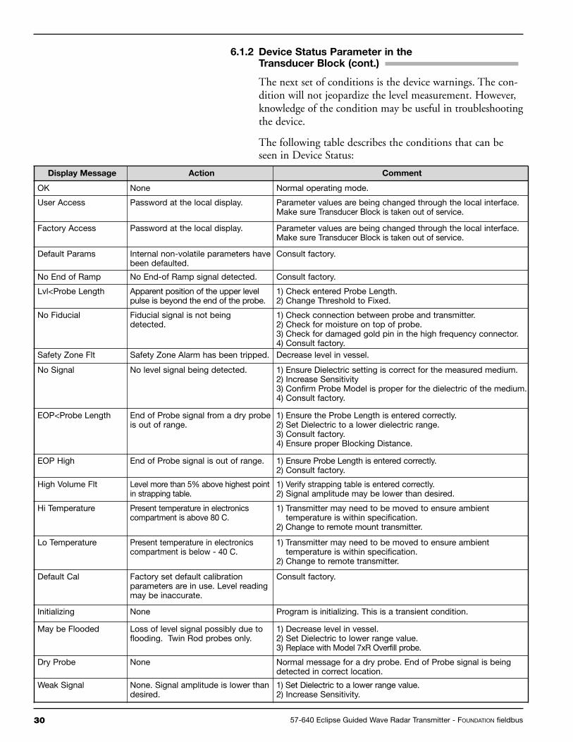
6.1.2 device Status Parameter in thetransducer Block (cont.)
The next set of conditions is the device warnings. The con-dition will not jeopardize the level measurement. However,knowledge of the condition may be useful in troubleshootingthe device.
The following table describes the conditions that can beseen in Device Status:
display Message action Comment
OK None Normal operating mode.
User Access Password at the local display. Parameter values are being changed through the local interface.Make sure Transducer Block is taken out of service.
Factory Access Password at the local display. Parameter values are being changed through the local interface.Make sure Transducer Block is taken out of service.
Default Params Internal non-volatile parameters havebeen defaulted.
Consult factory.
No End of Ramp No End-of Ramp signal detected. Consult factory.
Lvl<Probe Length Apparent position of the upper levelpulse is beyond the end of the probe.
1) Check entered Probe Length.2) Change Threshold to Fixed.
No Fiducial Fiducial signal is not beingdetected.
1) Check connection between probe and transmitter.2) Check for moisture on top of probe.3) Check for damaged gold pin in the high frequency connector.4) Consult factory.
Safety Zone Flt Safety Zone Alarm has been tripped. Decrease level in vessel.
No Signal No level signal being detected. 1) Ensure Dielectric setting is correct for the measured medium.2) Increase Sensitivity3) Confirm Probe Model is proper for the dielectric of the medium.4) Consult factory.
EOP<Probe Length End of Probe signal from a dry probeis out of range.
1) Ensure the Probe Length is entered correctly.2) Set Dielectric to a lower dielectric range.3) Consult factory.4) Ensure proper Blocking Distance.
EOP High End of Probe signal is out of range. 1) Ensure Probe Length is entered correctly.2) Consult factory.
High Volume Flt Level more than 5% above highest pointin strapping table.
1) Verify strapping table is entered correctly.2) Signal amplitude may be lower than desired.
Hi Temperature Present temperature in electronicscompartment is above 80 C.
1) Transmitter may need to be moved to ensure ambienttemperature is within specification.
2) Change to remote mount transmitter.
Lo Temperature Present temperature in electronicscompartment is below - 40 C.
1) Transmitter may need to be moved to ensure ambienttemperature is within specification.
2) Change to remote transmitter.
Default Cal Factory set default calibrationparameters are in use. Level readingmay be inaccurate.
Consult factory.
Initializing None Program is initializing. This is a transient condition.
May be Flooded Loss of level signal possibly due toflooding. Twin Rod probes only.
1) Decrease level in vessel.2) Set Dielectric to lower range value.3) Replace with Model 7xR Overfill probe.
Dry Probe None Normal message for a dry probe. End of Probe signal is beingdetected in correct location.
Weak Signal None. Signal amplitude is lower thandesired.
1) Set Dielectric to a lower range value.2) Increase Sensitivity.
3157-640 Eclipse Guided Wave Radar Transmitter - FOUNDATION fieldbus
6.1.3 FF Segment Checklist
There can be several reasons for a FOUNDATION fieldbus™
installation to be in a faulty condition. In order to ensurethat communication can be established, the followingrequirements must be met.
• Device supply voltage must be higher than 9 VDC with amaximum of 32 VDC.
• Total current draw of a given segment cannot exceed therating shown on the power conditioner and/or barrier.
• Device polarity must be correct.
• Two 100 Ω, 1 µF terminators must be connected to thenetwork—one at each end of the segment.
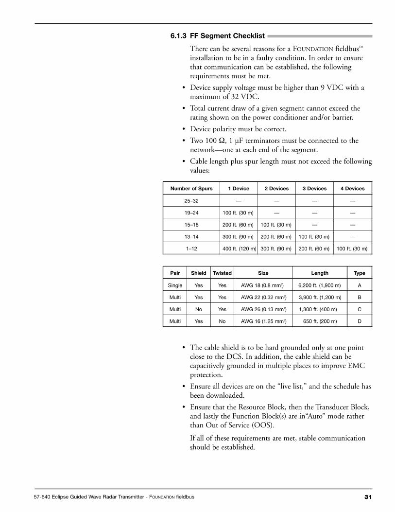
• Cable length plus spur length must not exceed the followingvalues:
• The cable shield is to be hard grounded only at one pointclose to the DCS. In addition, the cable shield can becapacitively grounded in multiple places to improve EMCprotection.
• Ensure all devices are on the “live list,” and the schedule hasbeen downloaded.
• Ensure that the Resource Block, then the Transducer Block,and lastly the Function Block(s) are in“Auto” mode ratherthan Out of Service (OOS).
If all of these requirements are met, stable communicationshould be established.
number of Spurs 1 device 2 devices 3 devices 4 devices
25–32 — — — —
19–24 100 ft. (30 m) — — —
15–18 200 ft. (60 m) 100 ft. (30 m) — —
13–14 300 ft. (90 m) 200 ft. (60 m) 100 ft. (30 m) —
1–12 400 ft. (120 m) 300 ft. (90 m) 200 ft. (60 m) 100 ft. (30 m)
Pair Shield twisted Size Length type
Single Yes Yes AWG 18 (0.8 mm2) 6,200 ft. (1,900 m) A
Multi Yes Yes AWG 22 (0.32 mm2) 3,900 ft. (1,200 m) B
Multi No Yes AWG 26 (0.13 mm2) 1,300 ft. (400 m) C
Multi Yes No AWG 16 (1.25 mm2) 650 ft. (200 m) D

32 57-640 Eclipse Guided Wave Radar Transmitter - FOUNDATION fieldbus
Appendix – Transducer Block Parameters
6.2 References
1. FOUNDATION fieldbus™, A Pocket Guide Ian Verhappen, Augusto Pereira2. FOUNDATION fieldbus™—System Engineering Guidelines, AG–181
ItEM PaRaMEtER naME PaRaMEtER LaBEL
0 BLOCK_STRUCTURE BLOCK STRUCT1 ST_REV ST REV2 TAG_DESC TAG DESC3 STRATEGY STRATEGY4 ALERT_KEY ALERT KEY5 MODE_BLK MODE BLK6 BLOCK_ERR BLOCK ERR7 UPDATE_EVT UPDATE EVT8 BLOCK_ALM BLOCK ALM9 TRANSDUCER_DIRECTORY XD DIRECTORY10 TRANSDUCER_TYPE XD TYPE11 XD_ERROR XD ERROR12 COLLECTION_DIRECTORY COLLECT DIR13 LEVEL Level14 LEVEL_UNIT Level Unit15 PROBE_LEVEL Probe Level16 PROBE_LEVEL_UNIT Probe Level Unit17 SENSOR_VALUE Sensor Value18 SENSOR_UNIT Sensor Unit19 SENSOR_OFFSET Sensor Offset20 CAL_TYPE Cal Type21 CAL_POINT_LO Cal Point Lo22 CAL_POINT_HI Cal Point Hi23 PROBE_LEVEL_LO Probe Lvl Lo24 PROBE_LEVEL_HI Probe Lvl Hi25 LEVEL_OFFSET Level Offset26 SENSOR_HIGH_LIMIT Sensor Hi Lmt27 SENSOR_LOW_LIMIT Sensor Lo Lmt28 PROBE_MODEL Probe Model29 PROBE_MOUNT Probe Mount30 MEASUREMENT_TYPE Measurement Type31 PROBE_LENGTH Probe Length32 DIELECTRIC_RANGE Dielctric Rng33 SENSITIVITY Sensitivity34 BLOCKING_DISTANCE Blocking Distance35 SAFETY_ZONE_MODE SafeZone Mode36 SAFETY_ZONE_HEIGHT SafeZone Ht37 SAFETY_ZONE_LATCH_RESET SZ Latch Rst38 THRESHOLD Threshold39 TRIM_LEVEL Trim Level40 LOCAL_AI_DISPLAY Local AI Display41 VOLUME Volume42 VOLUME_UNIT Volume Unit43 INTERFACE Interface44 INTERFACE_UNIT Ifc Unit45 UPPER_LIQUID_DIELECTRIC Upr Liq Diel46 INTERFACE_THRESHOLD Ifc Threshld47 INTERFACE_VOLUME Ifc Vol48 INTERFACE_VOLUME_UNIT Ifc Vol Unit49 STRAP_TABLE_LENGTH Strap Table Length50 TABLE_VOLUME_UNIT Table Volume Unit51 STRAPPING_TABLE_POINT01 StrapTbl Pt0152 STRAPPING_TABLE_POINT02 StrapTbl Pt0253 STRAPPING_TABLE_POINT03 StrapTbl Pt0354 STRAPPING_TABLE_POINT04 StrapTbl Pt0455 STRAPPING_TABLE_POINT05 StrapTbl Pt0556 STRAPPING_TABLE_POINT06 StrapTbl Pt0657 STRAPPING_TABLE_POINT07 StrapTbl Pt07
ItEM PaRaMEtER naME PaRaMEtER LaBEL
58 STRAPPING_TABLE_POINT08 StrapTbl Pt0859 STRAPPING_TABLE_POINT09 StrapTbl Pt0960 STRAPPING_TABLE_POINT10 StrapTbl Pt1061 STRAPPING_TABLE_POINT11 StrapTbl Pt1162 STRAPPING_TABLE_POINT12 StrapTbl Pt1263 STRAPPING_TABLE_POINT13 StrapTbl Pt1364 STRAPPING_TABLE_POINT14 StrapTbl Pt1465 STRAPPING_TABLE_POINT15 StrapTbl Pt1566 STRAPPING_TABLE_POINT16 StrapTbl Pt1667 STRAPPING_TABLE_POINT17 StrapTbl Pt1768 STRAPPING_TABLE_POINT18 StrapTbl Pt1869 STRAPPING_TABLE_POINT19 StrapTbl Pt1970 STRAPPING_TABLE_POINT20 StrapTbl Pt2071 FID_TICKS Fid Ticks72 FID_SPREAD Fid Spread73 LEVEL_TICKS Lvl Ticks74 INTERFACE_TICKS Ifc Ticks75 INTERFACE_MEDIUM Ifc Medium76 ENTER_PASSWORD Enter Password77 NEW_PASSWORD New User Password78 DEVICE_STATUS Device Status79 HISTORY_MESSAGE History Message80 HISTORY_CONTROL History Control81 RESET_HISTORY Reset History82 HF_CABLE HF Cable83 FID_TYPE Fid Type84 FID_GAIN Fid Gain85 WINDOW_705 Window86 CONVERSION_FACTOR Conv Factor87 SCALE_OFFSET Scale Offset88 NEGATIVE_THRESHOLD_AMPLITUDE NegThrsh Ampl89 INTERFACE_THRESHOLD_AMPLITUDE IfcThrsh Ampl90 POSITIVE_THRESHOLD_AMPLITUDE PosThrsh Ampl91 SIGNAL Signal92 COMPENSATION Compensation93 DERATE_FACTOR Derate Factor94 TARGET_AMPLITUDE Target Amplitude95 TARGET_TICKS Target Ticks96 TARGET_CAL Target Cal97 TARGET_OPERATING_MODE Target OperMode98 7XK_DISTANCE_CORRECTION 7XK Dist Corr99 ELECTRONICS_TEMPERATURE Elec Temp100 MAX_ELECTRONICS_TEMPERATURE Max Elec Temp101 MIN_ELECTRONICS_TEMPERATURE Min Elec Temp102 RESET_ELECTRONICS_TEMPERATURE Reset Elect Temp103 SAFETY_ZONE_HYSTERESIS SafeZone Hyst104 ECHO_SUMMARY Echo Summary105 ECHO_DATA Echo Data106 ECHO_DATA_INDEX EchoData Indx107 WAVEFORM_SELECTION Waveform Selection108 NSP_VALUE NSP Value109 FACTORY_PARAM_1 Factory Param 1110 FACTORY_PARAM_2 Factory Param 2111 STEAM_CAL_MOUNT Steam Cal Mount112 NON_VOL_STAT Non Vol Stat113 DATE_CODE Date Code114 MAGNETROL_SERIAL_NUMBER Magnetrol S/N115 FIRMWARE_VERSION Firmware Ver

3357-640 Eclipse Guided Wave Radar Transmitter - FOUNDATION fieldbus
Enhanced Model 705Eclipse Guided Wave Radar TransmitterFOUNDATION Fieldbus™ Configuration Data Sheet
Copy blank page and store calibration data for future reference and troubleshooting.Item Value Value Value
Vessel Name
Vessel #
Process Medium
Tag #
Electronics Serial # TROUBLESHOOTING
Probe Serial # Working Value Non-Working Value
Level
Volume (optional)
Interface (optional)
Interface Volume (opt.)
Probe Model
Probe Mount
Measurement Type
Sensor Units
Probe Length
Level Offset
Volume Units (opt.)
Strapping Table (opt.)
Dielectric
Sensitivity
Blocking Distance
Safety Zone Fault
Safety Zone Height
Safety Zone Alarm
Threshold
Interface Threshold
Level Trim
Level Ticks
A. I. Disp
Dev Addr
Interface Ticks (opt.)
Fid Ticks
<Software Version>

34 57-640 Eclipse Guided Wave Radar Transmitter - FOUNDATION fieldbus
Enhanced Model 705Eclipse Guided Wave Radar TransmitterFOUNDATION Fieldbus™ Configuration Data Sheet
Copy blank page and store calibration data for future reference and troubleshooting.Item Value Value Value TROUBLESHOOTING
Working Value Non-Working Value
FidTicks
FidSprd
Fid Type
HF Cable
Fid Gain
Window
Conv Fct
Scl Ofst
Neg Ampl
Pos Ampl
Signal
Compsate
DrateFct
Targ Ampl
Targ Tks
Targ Cal
OperMode
7xKCorr
ElecTemp
Max Temp
Min Temp
SZ Hyst
Name
Date
Time

3557-640 Eclipse Guided Wave Radar Transmitter - FOUNDATION fieldbus
Notes

www.magnetrol.com
BENELUX Heikensstraat 6, 9240 Zele, België -BelgiqueFRANCE Tel. +32 (0)52.45.11.11 • Fax. +32 (0)52.45.09.93 • E-Mail: [email protected] Alte Ziegelei 2-4, D-51491 Overath Tel. +49 (0)2204 / 9536-0 • Fax. +49 (0)2204 / 9536-53 • E-Mail: [email protected] B-506, Sagar Tech Plaza, Saki Naka Junction, Andheri (E), Mumbai - 400072 Tel. +91 22 2850 7903 • Fax. +91 22 2850 7904 • E-Mail: [email protected] Via Arese 12, I-20159 Milano Tel. +39 02 607.22.98 • Fax. +39 02 668.66.52 • E-Mail: [email protected] 198095 Saint-Petersburg, Marshala Govorova street, house 35, office 427 Tel. +7 812 320 70 87 • E-Mail: [email protected]. DAFZA Office 5EA 722 • PO Box 293671 • Dubai Tel. +971-4-6091735 • Fax +971-4-6091736 • E-Mail: [email protected] Unit 1 Regent Business Centre, Jubilee Road Burgess Hill West Sussex RH 15 9TLKINGDOM Tel. +44 (0)1444 871313 • Fax +44 (0)1444 871317 • E-Mail: [email protected]
BULLETIN N°: BE 57-640.0EFFECTIVE: AUGUST 2015SUPERSEDES: NewUNDER RESERVE OF MODIFICATIONS
IMPORTANTSERVICE POLICY
Owners of Magnetrol products may request the return of a control; or, any part of a control for complete rebuilding or replacement. They will be rebuilt or replaced promptly. Magnetrol International will repair or replace the control, at no cost tothe purchaser, (or owner) other than transportation cost if:
a. Returned within the warranty period; and,b. The factory inspection finds the cause of the malfunction to be defective material or workmanship.
If the trouble is the result of conditions beyond our control; or, is NOT covered by the warranty, there will be charges for labourand the parts required to rebuild or replace the equipment.In some cases, it may be expedient to ship replacement parts; or, in extreme cases a complete new control, to replace theoriginal equipment before it is returned. If this is desired, notify the factory of both the model and serial numbers of the control to be replaced. In such cases, credit for the materials returned, will be determined on the basis of the applicability ofour warranty.No claims for misapplication, labour, direct or consequential damage will be allowed.
RETURNED MATERIAL PROCEDURESo that we may efficiently process any materials that are returned, it is essential that a “Return Material Authorisation” (RMA)form will be obtained from the factory. It is mandatory that this form will be attached to each material returned. This form isavailable through Magnetrol’s local representative or by contacting the factory. Please supply the following information:
1. Purchaser Name2. Description of Material3. Serial Number and Ref Number4. Desired Action5. Reason for Return6. Process details
Any unit that was used in a process must be properly cleaned in accordance with the proper health and safety standardsapplicable by the owner, before it is returned to the factory.A material Safety Data Sheet (MSDS) must be attached at the outside of the transport crate or box.All shipments returned to the factory must be by prepaid transportation. Magnetrol will not accept collect shipments.All replacements will be shipped Ex Works.