Guidebook for the evaluation of stream morphological ...
84
IDRAIM – stream hydromorphological evaluation, analysis and monitoring system Guidebook for the evaluation of stream morphological conditions by the Morphological Quality Index (IQM) Version 1 Rome, March 2011 Massimo RINALDI Nicola SURIAN Francesco COMITI Martina BUSSETTINI
Transcript of Guidebook for the evaluation of stream morphological ...

IDRAIM – stream hydromorphological evaluation, analysis and monitoring system
Guidebook for the evaluation of stream morphological conditions by the
Morphological Quality Index (IQM) Version 1
Rome, March 2011
Massimo RINALDI Nicola SURIAN
Francesco COMITI Martina BUSSETTINI


Rome, March 2011
IDRAIM – stream hydromorphological evaluation, analysis and monitoring system
Guidebook for the evaluation of stream morphological conditions by the
Morphological Quality Index (IQM) Version 1
Massimo RINALDI Nicola SURIAN
Francesco COMITI Martina BUSSETTINI

IDRAIM – STREAM HYDROMORPHOLOGICAL EVALUATION, ANALYSIS AND MONITORING SYSTEM
i
LEGAL NOTICE Neither the Institute for Environmental Protection and Research, ISPRA (Istituto Superiore per la Protezione e la Ricerca Ambientale) nor any person acting on behalf of the Institute is responsible for the use that may be made of the information contained in this Guidebook. ISPRA (Istituto Superiore per la Protezione e la Ricerca Ambientale), has been established by Decree no. 112 of 25 June 2008, converted into Law no. 133 (with amendments) on 21 August 2008. ISPRA performs, with the inherent financial resources, equipment and personnel, the duties of: the Italian Environment Protection and Technical Services Agency (APAT), the National Institute for Wildlife (INFS) and the Central Institute for Scientific and Technological Research applied to the Sea (ICRAM). ISPRA – Istituto Superiore per la Protezione e la Ricerca Ambientale Via Vitaliano Brancati, 48 00144 Roma www.isprambiente.it © ISPRA 2011 ISBN: 978-88-448-0487-9 Reproduction is authorised, provided the source is acknowledged, save where otherwise stated. Graphic design ISPRA March 2011 Citation: Rinaldi M., Surian N., Comiti F., Bussettini M. 2011, GUIDEBOOK FOR THE EVALUATION OF STREAM MORPHOLOGICAL CONDITIONS BY THE MORPHOLOGICAL QUALITY INDEX (IQM), Istituto Superiore per la Protezione e la Ricerca Ambientale, Rome, 84 pp.

IDRAIM – STREAM HYDROMORPHOLOGICAL EVALUATION, ANALYSIS AND MONITORING SYSTEM
ii
Index
Introduction ............................................................................................................................. vi
CHAPTER 1 METHODOLOGICAL FRAMEWORK ....................................................... 1
1.1 Review of existing methods for hydromorphological evaluation ...................................... 1 1.2 Overall structure of the method ........................................................................................ 2
CHAPTER 2 GENERAL SETTING AND SEGMENTATION .......................................... 5
2.1 General framework ........................................................................................................... 5 2.2 STEP 1: General setting and physiographic units ............................................................. 5 2.3 STEP 2: Confinement ......................................................................................................... 6 2.4 STEP 3: Channel morphologies ......................................................................................... 7
2.4.1 Classification of semiconfined and unconfined channels ....................................... 7 2.4.2 Classification of confined channels ......................................................................... 8 2.4.3 Fluvial typologies .................................................................................................... 9
2.5 STEP 4: Other discontinuities ............................................................................................ 9 2.6 Example of segmentation ................................................................................................ 10 2.7 Other available data and information ............................................................................ 11
CHAPTER 3 EVALUATION OF MORPHOLOGICAL CONDITIONS ........................ 13
3.1 Evaluation procedure ..................................................................................................... 13 3.2 Scoring system ................................................................................................................ 16 3.3 Applications .................................................................................................................... 16
3.3.1 Sentino stream along the Frasassi gorge. .............................................................. 17 3.3.2 Tagliamento River near Turrida. ........................................................................... 17 3.3.3 Cecina River near Casino di Terra. ....................................................................... 18 3.3.4 Furkelbach (Furcia Torrent) in Val Pusteria. ........................................................ 19 3.3.5 Panaro River near Vignola. ................................................................................... 20 3.3.6 Arno River in Florence. ......................................................................................... 21 3.3.7 Gadria Torrent near Lasa. ...................................................................................... 22
CHAPTER 4 MONITORING ............................................................................................... 23
References ............................................................................................................................... 25
APPENDIX 1 GUIDE TO THE COMPILATION OF THE EVALUATION FORMS ................................. I
GUIDE TO THE COMPILATION OF THE EVALUATION FORMS ......................................................... 1
GENERALITY AND INITIAL SEGMENTATION ........................................................................................................ 1 Geomorphological Functionality .................................................................................................................. 1
CONTINUITY ............................................................................................................................................................... 1 F1: Longitudinal continuity in sediment and wood flux ..................................................................................... 1 F2: Presence of a modern floodplain ................................................................................................................. 2 F3: Hillslopes – river corridor connectivity ....................................................................................................... 2 F4: Processes of bank retreat ............................................................................................................................. 3 F5: Presence of a potentially erodible corridor ................................................................................................. 3
MORPHOLOGY ............................................................................................................................................................. 4 F6: Bed configuration – valley slope .................................................................................................................. 4 F7: Forms and processes typical of the channel pattern .................................................................................... 5 F8: Presence of typical fluvial forms in the alluvial plain .................................................................................. 6 F9: Variability of the cross-section .................................................................................................................... 6

IDRAIM – STREAM HYDROMORPHOLOGICAL EVALUATION, ANALYSIS AND MONITORING SYSTEM
iii
F10: Structure of the channel bed ...................................................................................................................... 7 F11: Presence of in-channel large wood ............................................................................................................ 8
VEGETATION IN THE FLUVIAL CORRIDOR ..................................................................................................................... 9 F12: Width of functional vegetation in the fluvial corridor ................................................................................ 9 F13: Linear extension of functional vegetation along the banks ...................................................................... 10
Artificiality .................................................................................................................................................. 11 UPSTREAM ALTERATION OF LONGITUDINAL CONTINUITY ........................................................................................... 11
A1: Upstream alteration of discharges ............................................................................................................. 11 A2: Upstream alteration of sediment discharges .............................................................................................. 13
ALTERATION OF LONGITUDINAL CONTINUITY IN THE REACH ....................................................................................... 15 A3: Alteration of discharges in the reach ......................................................................................................... 15 A4: Alteration of sediment transport in the reach ............................................................................................ 16 A5: Crossing structures .................................................................................................................................... 17
ALTERATION OF LATERAL CONTINUITY ...................................................................................................................... 17 A6: Bank protections ........................................................................................................................................ 17 A7: Artificial levees .......................................................................................................................................... 18
ALTERATION OF CHANNEL MORPHOLOGY AND/OR SUBSTRATE ................................................................................... 18 A8: Artificial changes of river course .............................................................................................................. 18 A9: Other grade control structures .................................................................................................................. 19
INTERVENTIONS OF MAINTENANCE AND REMOVAL ..................................................................................................... 19 A10: Sediment removal .................................................................................................................................... 19 A11: Wood removal .......................................................................................................................................... 20 A12: Vegetation management ........................................................................................................................... 21
Channel Changes ........................................................................................................................................ 22 V1: Changes in channel pattern ....................................................................................................................... 22 V2: Changes in channel width .......................................................................................................................... 23 V3: Bed-level changes ...................................................................................................................................... 24
SCORES ............................................................................................................................................................ 25 SUB-INDEXES ................................................................................................................................................... 25
APPENDIX 2 EVALUATION FORM FOR CONFINED CHANNELS ................................................... II
APPENDIX 3 EVALUATION FORM FOR SEMICONFINED OR UNCONFINED CHANNEL .............. III
APPENDIX 4 ILLUSTRATED GUIDE TO THE ANSWERS ..................... (PUBBLISHED SEPARATELY)

IDRAIM – STREAM HYDROMORPHOLOGICAL EVALUATION, ANALYSIS AND MONITORING SYSTEM
iv
List of figures
Figure 1.1 – General methodological framework illustrating the division in three phases and a list of the main aspects for each one. ....................................................................................................................................... 4 Figure 2.1 – Example of segmentation for the Cecina River (Central Italy). ........................................................ 11 Figure 3.1 – Sentino stream along the Frasassi Gorge (IQM = 0.92: Very good). ................................................ 17 Figure 3.2 – Tagliamento River near Turrida (IQM = 0.87: Very good). .............................................................. 18 Figure 3.3 – Cecina River near Casino di Terra (IQM = 0.78: Good). .................................................................. 19 Figure 3.4 – The Furkelbach (Furcia) Torrent in Val Pusteria (IQM = 0.46: Poor). ............................................. 20 Figure 3.5 – Panaro River near Vignola (IQM = 0.40: Poor). .............................................................................. 21 Figure 3.6 – Arno River in Florence (IQM = 0.11: Very poor). ............................................................................ 22 Figure 3.7 – Gadria Torrent near Lasa (IQM = 0.04: Very poor). ......................................................................... 22

IDRAIM – STREAM HYDROMORPHOLOGICAL EVALUATION, ANALYSIS AND MONITORING SYSTEM
v
List of tables
Table 2.1 – Definition of the confinement classes. .................................................................................................. 7 Table 2.2 – Criteria and threshold values of indexes or other distinctive characteristics for the morphological classification of semiconfined and unconfined channels. ........................................................................................ 8 Table 2.3 – Fluvial typologies deriving from the combination of confinement and morphology. ........................... 9 Table 3.1 – General framework of the indicators used to assess the morphological state. .................................... 13 Table 3.2 – List of indicators. ................................................................................................................................ 15 Table 4.1 – Morphological aspects, parameters, methodologies, and spatial scale for Instrumental Monitoring. . 24

IDRAIM – STREAM HYDROMORPHOLOGICAL EVALUATION, ANALYSIS AND MONITORING SYSTEM
vi
Introduction The Water Framework Directive (WFD) (EUROPEAN COMMISSION, 2000)
introduces hydromorphology as one of the elements to be evaluated, besides water quality and biological aspects, in order to obtain an evaluation and classification of the stream ecological state. Notwithstanding the innovations of the WFD, some limitations are recognised, amongst which hydromorphology appears to be the component taken least into consideration to eventually compromise the achievement of the fundamental objectives of the directive.
Nowadays a full comprehension of the morphological aspects and parameters more strictly correlated to the ecological state of a stream are still missing, even though several efforts have recently been devoted to this issue (see for example: KAIL & HERING, 2009; WYŻGA et al., 2009; GURNELL et al., 2009). A wide consensus, however, exists on the fact that geomorphic processes of streams and their dynamic equilibrium conditions spontaneously promote habitat diversity and the functioning of aquatic and riparian ecosystems (e.g. CLARKE et al., 2003; PALMER et al., 2005).
However, the approaches used up t o now in most European countries tend to reflect “River Habitat Survey” procedures (see for example the RHS in UK – RAVEN ET AL., 1998), which are suitable for defining the presence and diversity of physical habitats but which have not been developed to comply with the WFD requirements. Therefore, there is an increasing need for an approach based on the consideration and understanding of the geomorphological processes responsible for river functioning which can be used not only for a classification but also for supporting analyses of any interventions and impacts, and the design of mitigation measures. Some examples of new methods currently developed in Spain (Indice Idro-Geomorfologico, IHG – OLLERO ET AL., 2007) and in France (SYRAH procedure – CHANDESRIS et al., 2008) are a step in this direction.
A new system has been developed for stream morphological assessment and classification at a national level with a s eries of the requisites previously detailed (adequate spatial scales, consideration of processes and trends of channel evolution, etc.) and which, at the same time, would be sufficiently simple and practical (RINALDI et al., 2010). This document reports the main characteristics of the method and a concise guide for its application.
The Illustrated Guide To The Answers is part of the Guidebook and is published in a separated volume.

IDRAIM – STREAM HYDROMORPHOLOGICAL EVALUATION, ANALYSIS AND MONITORING SYSTEM
vii
AUTHORS AND ACKNOWLEDGEMENTS
Lead authors Massimo RINALDI: Dipartimento di Ingegneria Civile e Ambientale, Università di Firenze Nicola SURIAN: Dipartimento di Geografia, Università di Padova Francesco COMITI: Facoltà di Scienze e Tecnologie, Libera Università di Bolzano Martina BUSSETTINI: Istituto Superiore per la Protezione e la Ricerca Ambientale (ISPRA), Roma
Acknowledgements
CONTRIBUTORS - Phase of methodological definition:
Luisa Pellegrini (Università di Pavia), Andrea Colombo, Federica Filippi e Tommaso Simonelli (Autorità di Bacino del Fiume Po);
- ISPRA contributors:
Giovanni Braca, Barbara Lastoria, Francesca Piva, Saverio Venturelli;
- Testing phase:
P. Aucelli, V. Benacchio, M. Ceddia, C. Cencetti, A. Colombo, S. De Gasperi, P. De Rosa, A. Dignani, G. Duci, F. Filippi, A. Fredduzzi, M. Micheli, E. Morri, O. Nesci, L. Pellegrini, C. Rosskopf, R. Santolini, V. Scorpio, T. Simonelli, D. Sogni, S. Teodori, V. Tiberi, F. Troiani, C. Zuri.
- Final revision of the manuscript:
B. Lastoria, C. Zuri, B. Golfieri.
- Illustrated Guide To The Answers:
B. Lastoria, C. Zuri. Special thanks to Barbara Lastoria, for the editing and layout of the Guidebook and of the Illustrated Guide, and for the implementation of xls forms.

IDRAIM – STREAM HYDROMORPHOLOGICAL EVALUATION, ANALYSIS AND MONITORING SYSTEM
1
CHAPTER 1 METHODOLOGICAL FRAMEWORK
1.1 Review of existing methods for hydromorphological evaluation The term “hydromorphology” was introduced by t he WFD (EUROPEAN
COMMISSION, 2000), and includes the consideration of: (a) the extent of modification to the flow regime; (b) the extent to which water flow, sediment transport and the migration of biota are impacted by artificial barriers; (c) the extent to which the morphology of the river channel has been modified, including constraints to the free movement of a river across its floodplain (SEAR et al., 2003). Following the WFD, and according to definitions adopted by various authors (e.g. CEN, 2002; NEWSON & LARGE, 2006; MAAS & BROOKES, 2009; VOGEL, 2011), hydromorphology can be defined as the discipline that, by integrating hydrology and fluvial geomorphology, aims to study fluvial form and processes, their interactions with human impact, and the consequent implications on ecological processes.
Over recent years, several methods have been developed in many countries that are based on a census of physical habitats and diversity of fluvial forms, also known as river habitat survey procedures. Examples of those adopted in Europe and included in this category are as follows : the River Habitat Survey (RHS) (RAVEN et al., 1997), the National Physical Habitat Index (National Environmental Research Institute) in Denmark, the Physical S.E.Q. (AGENCES DE L’EAU, 1998) in France, and the Caravaggio (BUFFAGNI et al., 2005), the latter deriving from the RHS and adapted to the Italian and Mediterranean context. However, such methods were not originally developed to satisfy the requirements of the WFD. Among the main limitations of these methodologies, we note the following: (a) they make use of a “form-based approach” and do not include considerations on processes and trends of adjustment; (b) as a co nsequence, they define “reference conditions” in terms of forms (presence and number of given features) making use of “reference reaches” in present conditions (although they can be partially altered); (c) the spatial scale of investigation (coinciding with the “site”, with a length to the order of some hundreds of meters) is inadequate for a real diagnosis and comprehension of morphological problems, as the physical degradation of a site is generally the consequence of processes and causes on a w ider scale; (d) these procedures are not appropriate for an analysis of interventions and impacts aimed at the design of restoration actions, as required by the WFD. For example, let us consider a channel reach subject to intense adjustments (incision, narrowing) during the last decades, as very frequently occurred along many Italian rivers (e.g. SURIAN & RINALDI, 2003; SURIAN et al., 2009a). By using the RHS method, a census of present forms (i.e. bars, riffles, pools) and their number is carried out, and so the result could be relatively good (e.g. a reach changing from a braided to a single-thread morphology, but still maintaining a diversity of forms), completely neglecting the alterations of processes related to the channel adjustments (e.g. disconnection with floodplain, loss of aquatic and riparian habitats, etc.). Furthermore, the RHS value could vary significantly depending on the site of application (length of 500 m) that could reflect local conditions.
In Italy, besides the Caravaggio, the IFF is certainly worth mentioning (Indice di Funzionalità Fluviale: SILIGARDI et al., 2007), which evaluates the overall ecological functionality of a river reach. This, however, was not developed to

IDRAIM – STREAM HYDROMORPHOLOGICAL EVALUATION, ANALYSIS AND MONITORING SYSTEM
2
evaluate the degree of deviation from a given reference condition, neither does it include hydromorphological aspects in any detail. Recently, a methodological framework of integrated assessment of the ecological status was proposed (FLEA: Fluvial Ecosystem Assessment) (NARDINI et al., 2008), which is specific for the requirements of the WFD and also includes the elements of hydromorphological quality.
Recently, there has been an increasing development of new methods denoting a stronger geomorphological component, with an increasing consideration of physical processes, and the employment of sufficiently wide temporal scales and additional methods (remote sensing, GIS) integrated into field surveys. In this context, new methods developed in Spain (Indice Idro-Geomorfologico, IHG: OLLERO et al., 2007) and in France (SYRAH: Système Relationnel d’Audit de l’Hydromorphologie des Cours d’Eau, CHANDESRIS et al., 2008) are of particular note.
Finally, it is useful to mention some other methods existing in other countries not directly aimed at the application of the WFD but to stream evaluation and geomorphological analysis for management and restoration purposes. The Fluvial Audit (EA, 1998) can be included in this category, being a structured procedure aimed at the definition of management strategies and/or interventions. Another particularly significant example is that of the River Styles Framework (Australia), an organic methodological procedure for the detailed geomorphological analysis of a fluvial system developed by BRIERLEY & FRYIRS (2005).
1.2 Overall structure of the method The definition of the stream Morphological Quality Index (IQM) lies in a wider
methodological framework named IDRAIM (stream hydromorphological evaluation, analysis and monitoring system) also aimed at a subsequent analysis of the causes and the monitoring of evolution trends, further to a classification of the present morphological state.
The general procedure of classification and monitoring is based, according to the WFD requirements, on evaluating the deviation of present conditions from a given reference state. The definition of a reference state for hydromorphology is problematic, and the scientific community nowadays agrees to renounce considering a “pristine”, completely undisturbed condition. This is because, besides being extremely difficult to define, it would be associated with watershed conditions completely different from the present. It is therefore more appropriate to refer to the conditions that would exist in the present watershed conditions, but in the absence of human disturbances along the channel and adjacent river corridor. Recently, it has been increasingly necessary to refer to a “guiding image” coinciding with a condition of “dynamic equilibrium” (CLARKE et al., 2003; PALMER et al., 2005), i.e. of channel mobility, and to consider “reference processes” or “reference process-form interactions” (BERTOLDI et al., 2009) rather than “reference forms”. Furthermore the comprehension of the fluvial system evolutive trends (in some cases also indicated as “trajectory”: BRIERLEY & FRYIRS, 2005; DUFOUR & PIÉGAY, 2009) is important not in the perspective of the recovery to a past condition but to ensure that future actions would be compatible with the trends of channel adjustment. To this aim, we refer to recent research in the fields of fluvial geomorphology and dynamics carried out on a national scale during the last years, by which the procedures of channel change analysis have been

IDRAIM – STREAM HYDROMORPHOLOGICAL EVALUATION, ANALYSIS AND MONITORING SYSTEM
3
improved and channel evolution conceptual models have been developed (see for example RINALDI, 2008; RINALDI et al., 2008; SURIAN, 2009a).
Starting from these premises, the evaluation of present conditions and future monitoring are based on an integrated approach, making a synergic use of the two main methodologies employed in the geomorphological study of rivers: field survey and interpretation, and remote sensing and GIS analyses.
Regarding the spatial scales, a h ierarchical nested approach is adopted
(BRIERLEY & FRYIRS, 2005), considering the following spatial units of decreasing hierarchy: (1) CATCHMENT; (2) PHYSIOGRAPHIC UNITS AND FLUVIAL SEGMENTS (the latter having lengths to the order of tens of km); (3) STREAM REACHES (with lengths normally to the order of 1÷5 km), corresponding to the basic unit for remote sensing and GIS analyses; (4) SITES, consisting of a representative sub-reach and corresponding to the basic unit for field survey; (5) SEDIMENTARY UNITS, useful for measurements of detail (for example grain size analysis of bed sediments).
The overall procedure of morphological analysis includes (Figure 1.1):
(1) Initial setting and classification: the main physical aspects determining the configuration and characteristics of the hydrographic network are identified, and a first delineation of the rivers in segments and reaches is carried out.
(2) Evaluation of the current morphological conditions: the morphological state of the river reaches previously defined is evaluated in terms of present conditions (functionality, artificiality), and recent channel changes.
(3) Monitoring: for some reaches, selected as representative, a ser ies of parameters are measured to evaluate if the morphological quality of the stream remains unaltered or is changing.
For the current morphological state assessment, coherently with CEN (2002) standards and WFD requirements, the following aspects are considered: (a) longitudinal and l ateral continuity; (b) channel pattern; (c) cross-section configuration; (d) bed structure and s ubstrate; (e) vegetation in the riparian corridor.
Then, the following three components of morphological analysis are
considered:
(1) Geomorphological functionality: based on the observation of forms and processes in the present conditions, and their comparison with forms and processes normally associated with that river typology.
(2) Artificial elements: presence, frequency and continuity of artificial structures and interventions.
(3) Channel changes: recent morphological variations (with particular reference, for the planimetric changes, to the last 50÷60 years).
Following this framework, the reference conditions for a study reach can be identified with the following: (a) functionality of the processes, corresponding to dynamic equilibrium conditions; (b) absence of artificiality; (c) absence of significant adjustments of form, size and bed elevation in a time interval of the last decades.

IDRAIM – STREAM HYDROMORPHOLOGICAL EVALUATION, ANALYSIS AND MONITORING SYSTEM
4
Figure 1.1 – General methodological framework illustrating the division in three phases
and a list of the main aspects for each one.
As schematically represented in Figure 1.1, the morphological analysis described here only includes those hydrological aspects related to alterations of channel-forming discharges, i.e. those with more significant effects on morphological processes. The overall changes in the hydrologic regime (with particular emphasis on low discharges) are analysed separately and described in ISPRA (2009). In short, the analysis of the hydrological regime is carried out on a stream section on the basis of a Hydrological Regime Alteration Index, IARI, that provides a measure of the deviation between the observed hydrological regime and the natural regime in the absence of human intervention. The IARI index is obtained, dependent on available river discharge data quality and consistency, by comparing the daily and/or monthly discharges actually flowing through the cross section and the corresponding natural discharges. The integration of morphological and hydrological aspects allows for a c omplete characterization and classification of stream hydromorphology.

IDRAIM – STREAM HYDROMORPHOLOGICAL EVALUATION, ANALYSIS AND MONITORING SYSTEM
5
CHAPTER 2 GENERAL SETTING AND SEGMENTATION
2.1 General framework The first phase of the evaluation procedure provides a general setting of the
river’s physical conditions and for a first classification in relatively homogeneous reaches, functional to subsequent analyses. This phase is divided into the following steps:
(1) General setting and identification of the physiographic units. A first division of the watershed into macro-areas (physiographic units) and into corresponding macro-reaches (segments) is carried out.
(2) Definition of the confinement degree. River confinement (confined, semi-confined, unconfined) is defined more in detail, obtaining a preliminary subdivision of segments into reaches.
(3) Definition of channel morphology. Channel morphology is then defined, using different criteria for confined and semi- unconfined river reaches.
(4) Division into reaches. The final definition of reaches takes into account, besides confinement and channel morphology, additional factors such as hydrologic discontinuities, channel slope, artificiality, alluvial plain size, etc.
2.2 STEP 1: General setting and physiographic units Aim: to obtain a general setting of the physiographic context and carry out a first division into macro-areas (physiographic units) and macro-reaches (segments). Information/data necessary: watershed area, dominant lithologies, climate and hydrologic regime, land use, longitudinal profiles. Methods: consultation of geological, geomorphological, and land use maps; existing studies; hydrological data collection and analysis; Remote sensing /GIS; field reconnaissance. Results: division of the catchment into physiographic units and of the rivers into segments.
Description: based on t he collection and consultation of existing materials, the main physiographic units in the catchment are identified (these correspond to the landscape units of according to BRIERLEY & FRYIRS, 2005). They can be included in two general physiographic areas: (1) hills – mountains; (2) plains. In Italy, the following main physiographic units can be identified:
(A) Alpine and P o plain sectors: (1) Alpine mountain areas; (2) Pre-alpine mountain and hilly areas; (3) High plains; (4) Low plains.
(B) Apenninic and island sectors: (1) Mountain Apenninic areas; (2) Hilly Apenninic areas; (3) Intermontane Apenninic plains; (4) Inner reliefs; (5) High plains; (6) Low plains.
The portions of streams included within a physiographic unit are defined as segments. However, within a same physiographic unit, a stream may be further divided into more segments depending on the macro-characteristics of the valley (e.g. main changes of direction due to tectonic controls) and/or on relevant changes in bed slope from the longitudinal profile (particularly in the cases of

IDRAIM – STREAM HYDROMORPHOLOGICAL EVALUATION, ANALYSIS AND MONITORING SYSTEM
6
mountain confined streams). Segments normally have a length to the order of some km (mountain areas) and up to tens of km (lowland areas).
2.3 STEP 2: Confinement Aim: to define in more detail the confinement conditions, and to sub-divide segments based on confinement parameters. Information/data necessary: width of the alluvial plain, confinement degree, confinement index. Methods: Remote sensing /GIS; topographic and geological maps. Results: division of segments based on confinement parameters. Description: to analyze the confinement in detail, two parameters are used: (1) confinement degree; (2) confinement index.
(1) Confinement degree. This expresses the lateral confinement in a longitudinal sense, independently from the width of the alluvial plain. It corresponds to the percentage of banks directly not in contact with the alluvial plain but with hillslopes or ancient terraces, over the total length of the two banks. As a practical rule, the alluvial plain (i.e. the maximum width of the fluvial area of investigation) is normally identified on ge ological maps with “present alluvium” or “Holocene alluvium”. However, an altimetric criterion can be more necessary than a rigid chronological criterion: if the Holocene alluvium is terraced, only some meters of it can be included in the alluvial plain (i.e. a Holocene terrace of 10÷15 m is not part of the alluvial plain). Vice versa, a Pleistocene terrace separated by a difference in level of few meters can be considered part of the alluvial plain, except when the material is strongly cemented. In any case, terraces delimiting the alluvial plain are ancient ones: recent terraces generated by c hannel bed incision during the last 100÷200 years, as very frequently occurred in Italy, for the purpose of the confinement are part of the alluvial plain. According to BRIERLEY & FRYIRS (2005), three cases can be distinguished based on the confinement degree: - Confined channels: more than 90% of the banks are directly in contact
with hillslopes or ancient terraces. The alluvial plain is limited to some isolated pockets (< 10%).
- Semiconfined (or partly confined) channels: banks are in contact with the alluvial plain for a length from 10 to 90%.
- Unconfined channels: less than 10% of the bank length is in contact with hillslopes or ancient terraces. In fact, the alluvial plain is nearly continuous, and the river has no lateral constraints to its mobility.
In some cases, the confinement degree previously defined is not sufficient to appropriately define the confinement characteristics. In fact, it is not infrequent (particularly in mountain areas) to have streams with a very narrow (some meters) but quite continuous plain on the sides before entering in contact with the hillslopes. According to the previous definitions, such streams may fall into the categories of semiconfined or unconfined, while it is more appropriate for the aims of this method to consider them as confined. Therefore, an additional parameter is used here which takes into account the confinement in a transversal sense (i.e. considering the width of the alluvial plain), defined as follows.

IDRAIM – STREAM HYDROMORPHOLOGICAL EVALUATION, ANALYSIS AND MONITORING SYSTEM
7
(2) Confinement index. It is defined here as the ratio between the alluvial plain width (including the channel) and the channel width. Consequently, the index is inversely proportional to the confinement: a minimum value of 1 indicates that the alluvial plain and channel coincide (i.e. there is no alluvial plain), while the index increases when the alluvial plain increases its width relatively to the channel width. Based on the confinement index, the following classes are defined: - high confinement: index ranging from 1 to 1.5; - medium confinement: index ranging from 1.5 to n; - low confinement: index higher than n;
where n = 5 for single-thread channels (including sinuous with alternate bars), and n = 2 for multi-thread or transitional morphologies. The highest value for single-thread channels reflects the fact that a sufficiently wide plain is needed for these channels to develop completely free meanders, equal to about 4.5 times the channel width (LEOPOLD & WOLMAN, 1957).
Based on the confinement degree and index, it is possible to define the three final classes of confinement, according to Table 2.1.
Table 2.1 – Definition of the confinement classes.
CONFINEMENT CLASS DESCRIPTION Confined All cases with confinement degree > 90%
Confinement degree from 10% to 90% and confinement index ≤ 1.5
Semiconfined Confinement degree from 10% to 90% and confinement index > 1.5 Confinement degree < 10% and confinement index ≤ n
Unconfined Confinement degree < 10% and confinement index > n
2.4 STEP 3: Channel morphologies Aim: to define and classify channel morphologies. Information/data necessary: confinement, sinuosity index, braiding index, anastomosing index (bed configuration). Methods: Remote sensing /GIS; field reconnaissance. Results: division of segments based on channel morphology. Description: criteria for the classification of channel morphology are slightly differentiated for semi- unconfined channels and confined channels.
2.4.1 Classification of semiconfined and unconfined channels Semiconfined and unconfined channels are classified based on their planimetric
characteristics, therefore using the following classical indexes: (1) sinuosity index; (2) braiding index; (3) anastomosing index.
- SINUOSITY INDEX (Si) is defined as t he ratio between the distance measured along the channel and the distance measured following the direction of the overall planimetric course.

IDRAIM – STREAM HYDROMORPHOLOGICAL EVALUATION, ANALYSIS AND MONITORING SYSTEM
8
- BRAIDING INDEX (Bi) is defined as the number of active channels separated by bars.
- ANASTOMOSING INDEX (Ai) is defined as t he number of active channels separated by vegetated islands.
Based on these parameters and, in some cases, on additional qualitative features (see Table 2), the following seven channel morphologies included in three main categories are defined:
- Single-thread channels: straight, sinuous, meandering - Transitional channels: sinuous with alternate bars, wandering - Multi-thread channels: braided, anastomosed.
In Table 2.2 the criteria and threshold values of the indexes are reported. These have been defined according to the existing literature (e.g. LEOPOLD & WOLMAN, 1957; SCHUMM, 1977; BRICE, 1984; CHURCH, 1992; THORNE, 1997; etc.), but also taking into account specific experience relative to the Italian context (e.g. RINALDI, 2003; SURIAN & RINALDI, 2003; SURIAN et al., 2009b). For example, sinuous with alternate bars (or “pseudomeandering”: BARTHOLDY & BILLI, 2002; RINALDI, 2003) are here considered as a separate morphology, although in the following phase of assessment they are often grouped with single-thread channels for practical reasons, while wandering are grouped with multi-thread channels. Table 2.2 – Criteria and threshold values of indexes or other distinctive characteristics for the morphological classification of semiconfined and unconfined channels.
TYPOLOGY SINUOSITY INDEX BRAIDING INDEX ANASTOMOSING INDEX
Straight (ST) 1 ≤ Si < 1.05 1÷1.5 (normally equal or close to 1)
1÷1.5 (normally equal or close to 1)
Sinuous (S) 1.05 ≤ Si < 1.5 1÷1.5 (normally equal or close to 1)
1÷1.5 (normally equal or close to 1)
Meandering (M) ≥ 1.5 1÷1.5 (normally equal or close to 1)
1÷1.5 (normally equal or close to 1)
Sinuous with alternate bars (SAB) < 1.5 Close to 1 Close to 1
Wandering (W) < 1.5 1 < Ii < 1.5 1 < Ia < 1.5
Braided (B) Any (normally low) ≥1.5 <1.5
Anastomosed (A) any (even > 1.5) 1÷1.5 ≥ 1.5 Other distinctive characteristics
Straight (ST) or sinuous (S)
Compared to SAB/W: discontinuous (or absent) side bars (length of side bars < 80% of reach length)
Sinuous with alternate bars (SAB)
Compared to ST/S: nearly continuous presence of side bars (length of side bars normally > 80%). Compared to W: relatively narrower channel; absence (or localized presence) of braiding and anastomosing.
Wandering (W) Compared to ST/S: nearly continuous presence of side bars (length of side bars normally > 80%). Compared to SAB: relatively wider channel; significant presence of braiding and/or anastomosing phenomena.
2.4.2 Classification of confined channels Confined channels are classified, at a first level, based on the same criteria used
for semi- and unconfined channels. The main difference is that the sinuosity index is not used, as it is not a significant parameter in distinguishing channel

IDRAIM – STREAM HYDROMORPHOLOGICAL EVALUATION, ANALYSIS AND MONITORING SYSTEM
9
morphologies, given that the planimetric configuration of a single-thread confined channel is controlled by the hillslopes. Therefore, all single-thread morphologies (including transitional sinuous with alternate bars) are not further classified. This results in four possible morphologies, divided in two main categories:
- Confined single-thread (including sinuous with alternate bars); - Confined multi-thread / Wandering: braided, anastomosed, wandering.
A second level of classification of confined channels is based on bed configuration. This level is not necessary for the segmentation, but additional information on be d configuration is useful for channel definition and as an indicator in the following phase of morphological assessment. According to existing literature (e.g. MONTGOMERY & BUFFINGTON, 1997; WOHL, 2000; LENZI et al., 2000; etc.), the following bed morphologies are distinguished:
- Bedrock channels; - Colluvial channels; - Mobile bed: cascade/step pool, plane bed, riffle pool, dune ripple; - Artificial bed.
2.4.3 Fluvial typologies From the combination of confinement and morphology, 18 fluvial typologies
are obtained, as listed in Table 2.3. Table 2.3 – Fluvial typologies deriving from the combination of confinement and morphology. CONFINEMENT MORPHOLOGY TYPOLOGY
Confined
Single-thread Wandering
Braided Anastomosed
(1) Confined single-thread (2) Confined wandering (3) Confined braided (4) Confined anastomosed
Semiconfined
Straight Sinuous
Meandering Sinuous with alternate
bars Wandering
Braided Anastomosed
(5) Semiconfined straight (6) Semiconfined sinuous (7) Semiconfined meandering (8) Semiconfined sinuous with alternate bars (9) Semiconfined wandering (10) Semiconfined braided (11) Semiconfined anastomosed
Unconfined
(12) Unconfined straight (13) Unconfined sinuous (14) Unconfined meandering (15) Unconfined sinuous with alternate bars (16) Unconfined wandering (17) Unconfined braided (18) Unconfined anastomosed
2.5 STEP 4: Other discontinuities Aim: to finalize the segmentation into relatively homogeneous reaches accounting also for additional factors. Information/data necessary: hydrologic discontinuities (tributaries, dams), artificiality, width of alluvial plain, channel width, longitudinal profile.

IDRAIM – STREAM HYDROMORPHOLOGICAL EVALUATION, ANALYSIS AND MONITORING SYSTEM
10
Methods: Remote sensing/GIS; longitudinal profile by t opographic maps; field reconnaissance. Results: segments are divided into reaches that are the elementary units for the following morphological assessment. Description: the following additional aspects are considered in this step as criteria for a further division into channel reaches.
- Discontinuities in bed slope. This is particularly important in the case of confined channels where the morphology is not a sufficient criterion in many cases to finalize the segmentation.
- Natural or artificial hydrological discontinuities. Tributaries determining significant changes in discharges or sediment transport can be considered. Artificial discontinuities are mainly identified with dams that necessarily correspond to a limit between reaches. Similarly, check dams or diversion structures of relevant sizes are normally considered as a limit of the reach, excluding the cases of a sequence of check dams that can be included in the same reach (if their distance is small relatively to the channel width).
- Artificiality. Normally, the segmentation is quite independent from artificial elements, being based on physical characteristics. An exception (besides the presence of dams or other transversal structures described in the previous point) may be the case of a portion of stream with a very high degree of artificiality, well distinguished from its upstream and downstream reaches. An example can be a river crossing an urban area, with completely fixed banks and artificial levees, or a mountain stream with a sufficiently long portion with bed revetments and/or a sequence of consolidation check dams.
- Changes in width of the alluvial plain and/or confinement index: in some cases, this can be considered as an additional criterion.
- Changes in channel width: marked variations in channel width can be an additional criterion.
- Changes in sediment size: cases of a considerable and sudden change in sediment size, e.g. a p assage from gravel-bed to sand-bed, can be considered a criterion of separation in different reaches.
2.6 Example of segmentation As an example of initial classification, the case of the Cecina River (Tuscany)
is illustrated in Figure 2.1, where the physiographic units, river segments and reaches are reported. The watershed is divided into three physiographic units: (1) hilly – mountainous unit (HM): this is a mainly hilly zone but with portions up to 1,000 m a.s.l., included in the inner Apenninic reliefs (“Metalliferous hills”), with a substrate predominantly composed of sedimentary rocks of the Ligurian and Tuscan units, with a significant presence of magmatic intrusive rocks; (2) hilly unit (H): this includes a wide area occupying most of the watershed, predominantly characterized by s oft rocks of Miocene and Pliocene, and Quaternary marine and fluvial deposits; (3) coastal plain unit (CP): this is limited to about the last 4 km of the Cecina River, and is characterized by recent alluvial deposits and coastal dunes, absence of confinement, and low gradients. From the intersection of the physiographic units with the Cecina river course, a first division into 3 segments is obtained. However, the portion of river included in the hilly unit

IDRAIM – STREAM HYDROMORPHOLOGICAL EVALUATION, ANALYSIS AND MONITORING SYSTEM
11
is further divided into two segments based on the confinement: segment 2 i s an alternation of semiconfined and confined reaches; segment 3 is characterized by the continuous presence of alluvial deposits and, as a consequence, only by semi-unconfined reaches. The further division into reaches accounts for the differences in channel morphology and other elements of discontinuity. The result is that the river is divided into a total of 18 reaches (on a total length of the river of about 80 km, implying that the reaches have a mean length of 4.45 km), with the codes of each reach defined in increasing order for each segment (as reported in Figure 2.1).
A B
C
D
Figure 2.1 – Example of segmentation for the Cecina River (Central Italy). (HM): Hilly – Mountainous unit; (H): Hilly unit; (CP): Coastal Plain unit.
2.7 Other available data and information To conclude the general setting and segmentation phase, a f urther series of
data/information can be collected, when available, concerning the following aspects.
- Drainage area. The drainage area of the watershed at the closure of a given reach is useful for some indicators in the following morphological assessment.
- Sediment size. Measurements of sediment size are not strictly required in the following phase of assessment. However, this information is very useful when it is available (e.g. from previous studies).
- Water discharges. In this phase, it is useful to identify all gauging stations in the catchment with a series of discharges over a sufficiently long time,

IDRAIM – STREAM HYDROMORPHOLOGICAL EVALUATION, ANALYSIS AND MONITORING SYSTEM
12
and to obtain the main representative discharges, such as the mean annual daily discharge, Q1.5, and discharges with higher return intervals.
- Sediment discharges. Although this type of information is difficult to obtain, existing estimations or measurements of sediment transport or sediment budgets are very useful when available (e.g. from previous projects or scientific literature).
- Alterations of water and sediment discharges in the catchment. It i s already helpful at this stage to carry out a complete collection of available information and data on t he possible alterations of water and sediment discharges. This will be needed for the definition of some indicators (A1 and A2) in the following phase. It is important to know the existence and position of the main structures of interception of sediment transport (dams, check dams, weirs, etc.), as w ell as the interventions of the possible alteration of water discharges (dams, diversions, spillways, retention basins, etc.). It is also important to collect information about the use of some of these interventions from the agencies in charge of their management and maintenance (e.g. use of a dam for hydropower or for a reduction in peak discharges, changes in discharge for given return intervals, existence of measures for sediment release, etc.). Possibly, a GIS-based map with identification of the main structures potentially altering sediment and water discharges and relative information should be produced.

IDRAIM – STREAM HYDROMORPHOLOGICAL EVALUATION, ANALYSIS AND MONITORING SYSTEM
13
CHAPTER 3 EVALUATION OF MORPHOLOGICAL CONDITIONS
3.1 Evaluation procedure The assessment of present morphological conditions is applied to any reach
defined in the previous phase by a nalyzing the following aspects, coherently with CEN (2004) standards and WFD requirements: (1) continuity of river processes, including (a) longitudinal continuity, and (b) lateral continuity; (2) channel morphological conditions, including (a) channel pattern, (b) cross-section configuration, and (c) bed structure and substrate; (3) vegetation. These aspects are analyzed according to three components: (1) geomorphological functionality; (2) artificiality; (3) morphological channel changes. The complete set of indicators can be schematically represented by crossing the previous aspects (in rows) and components (in columns) (Table 3.1), while the list of indicators is reported in Table 3.2.
Table 3.1 – General framework of the indicators used to assess the morphological state. Artificiality: the indicators having a secondary impact on the morphological aspect indicated in the row are in parentheses.
FUNCTIONALITY ARTIFICIALITY CHANNEL CHANGES
CONTINUITY Longitudinal F1 A1, A2, A3, A4, A5
Lateral F2, F3, F4, F5 A6, A7
MORPHOLOGY
Channel pattern F6, F7, F8 A8 (A6) V1
Cross-section F9 (A4, A9, A10) V2, V3
Bed substrate F10, F11 A9, A10, A11
VEGETATION F12, F13 A12 All indicators are investigated by using specific evaluation forms that allow for a
guided analysis using an integrated approach of remote sensing / GIS and field surveys. The evaluation forms are presented in two formats: (a) “field evaluation forms” (hard copy are in this Guidebook); (b) “electronic evaluation forms” (Excel format, that can be downloaded from the web page http://www.sintai.sinanet.apat.it/view/index.faces), to be compiled after the field survey.
A number of indicators are used, where each indicator is evaluated by one or more quantitative or qualitative variables (for some indicators, particularly for functionality, interpretative observations rather than quantitative parameters are used). Two evaluation protocols are defined for the two situations of: (1) confined channels; (2) semi- unconfined channels. Morphological changes are evaluated for large channels (width > 30 m), either for semi- unconfined and for confined streams.
For each indicator, in most cases three possible answers are defined (except for a limited number with two or four answers): (A) unaltered conditions or no significant alterations; (B) intermediate conditions; (C) high level of alterations. A Guide to the compilation of the evaluation forms is to be found at the end of this report.
In order to obtain a classification, it was necessary to define an objective evaluation procedure. The criterion utilized here is included within the evaluation scoring systems: scores are assigned to each indicator proportionally to its importance in the overall evaluation.

IDRAIM – STREAM HYDROMORPHOLOGICAL EVALUATION, ANALYSIS AND MONITORING SYSTEM
14
The procedure developed, although relatively simple, includes a high number of indicators (28): rather than selecting a few significant indicators, it was preferable to consider all aspects for an overall assessment or audit in order to achieve a systematic and organized analysis of the problem. For example, human disturbances are evaluated in two ways: on the one hand, their assessment as artificial elements and on the other, the assessment of their impacts on the functionality of processes and on channel adjustments. Indicators of functionality require some interpretative level of morphological forms and processes, rather than the measurement of given parameters, therefore they need expertise and specific knowledge of the field of investigation.
The evaluation is carried out by making a synergic use of two types of observations and measurements: (1) remote sensing and GIS analysis; (2) field survey. A succession of the following operative phases is recommended: (1) collection of existing material and information on t he reach and catchment; (2) observation and analysis of remote sensing images: during this phase many indicators can be already determined, and a list of the critical points which need to be resolved in the field; (3) field survey: this phase is concentrated on a representative sub-reach, but also includes a ch eck on some specific points along the reach (the “field evaluation forms” are compiled during phases 2 and 3); (4) final measurements from remote sensing – GIS and/or collection of additional information: once the critical points have been resolved in the field, it is possible to finalize the evaluation (the “electronic evaluation forms” are compiled at this stage). In some cases in this phase, additional information may be needed for some indicator (e.g. information on interventions or management activities by public agencies).

IDRAIM – STREAM HYDROMORPHOLOGICAL EVALUATION, ANALYSIS AND MONITORING SYSTEM
15
Table 3.2 – List of indicators. GEOMORPHOLOGICAL FUNCTIONALITY Longitudinal continuity
F1 Longitudinal continuity in sediment and wood flux Lateral continuity
F2 Presence of a modern floodplain F3 Hillslopes – river corridor connectivity F4 Processes of bank retreat F5 Presence of potentially erodible corridor
Channel pattern F6 Bed configuration – valley slope F7 Forms and processes typical of the channel pattern F8 Presence of typical fluvial forms in the alluvial plain
Cross-section configuration F9 Variability of the cross-section
Bed structure and substrate F10 Structure of the channel bed F11 Presence of in-channel large wood
Vegetation F12 Width of functional vegetation in the fluvial corridor F13 Linear extension of functional vegetation
ARTIFICIALITY Upstream alteration of longitudinal continuity
A1 Upstream alteration of discharges A2 Upstream alteration of sediment discharges
Alteration of longitudinal continuity in the reach A3 Alteration of discharges in the reach A4 Alteration of sediment discharges in the reach A5 Crossing structures
Alteration of lateral continuity A6 Bank protections A7 Artificial levees
Alteration of channel morphology and/or substrate A8 Artificial changes of river course A9 Other grade control structures
Interventions of maintenance and removal A10 Sediment removal A11 Wood removal A12 Vegetation management
CHANNEL CHANGES V1 Changes in channel pattern V2 Changes in channel width V3 Bed-level changes

IDRAIM – STREAM HYDROMORPHOLOGICAL EVALUATION, ANALYSIS AND MONITORING SYSTEM
16
3.2 Scoring system For each indicator, the scores to be assigned to each answer are reported on the
evaluation form, proportionally to the degree of alteration, that is, in increasing order from A (score 0) to C (maximum score for that indicator). Furthermore, in the evaluation system a judgement on t he degree of confidence is introduced for each answer, considering high, medium, and low confidence. In fact, cases with missing information or data are possible. It is therefore useful to distinguish the different cases a posteriori. This system will yield a simplified estimation of the overall uncertainty degree associated with the final evaluation. This is the range of variation of the final score, calculating for low confidence answers values which should be assigned in the case of answer variations.
Regarding the final score, initially the total deviation Stot from non altered conditions is calculated as t he sum of the scores assigned to all indicators. A Morphological Alteration Index (IAM) is then defined as:
IAM = Stot / Smax
where Smax is the maximum possible deviation for the given stream typology (corresponding to the sum of the scores of class C for all the questions applicable to the study case). Such an index ranges therefore from a minimum of 0 (no alteration) to a maximum of 1 (maximum alteration).
Regarding the score of artificiality, an additional score (of 12) is assigned to conditions of extremely high density for some types of intervention (weirs, revetments, bank protections, and levees).
A stream Morphological Quality Index (IQM) is then defined as complementary to the previous one, that is:
IQM = 1 – IAM
Such an index, contrary to the IAM, assumes a value of 0 in the case of maximum alteration, and a value of 1 i n the case of reference conditions (corresponding to maximum functionality, minimum artificiality and minimum channel changes). Based on IQM, five classes of morphological quality are defined as follows:
(1) very good or high: IQM > 0.85; (2) good: IQM = 0.7÷0.85; (3) moderate: IQM = 0.5÷0.7; (4) poor: IQM = 0.3÷0.5; (5) very poor or bad: IQM = 0÷0.3.
The scores assigned to the indicators and to the limits of the quality classes have been verified and better defined on the basis of a testing phase carried out on about 60 reaches representative of different morphological conditions (confined, semi- unconfined, meandering, braided, etc.) and of various situations of artificiality (ranging from relatively natural to highly artificial streams).
3.3 Applications A series of examples of applications (in decreasing order of IQM) to a range of
Italian rivers is reported as follows.

IDRAIM – STREAM HYDROMORPHOLOGICAL EVALUATION, ANALYSIS AND MONITORING SYSTEM
17
3.3.1 Sentino stream along the Frasassi gorge. The first example is a mountain stream along a co nfined reach, with a mean
channel width of 12 m and slope of 0.004. The channel is classified as confined single thread, banks are often composed of rock outcropping (Figure 3.1A), the channel bottom alternates between areas of substrate outcropping and subreaches with cobble and gravel and a riffle-pool configuration (Figure 3.1B). Channel gradient is in fact not very high, as the stream is not in its initial part but at the passage between two semi-confined reaches. Channel changes are not considered given the limited channel width (< 30 m). There are no significant alterations compared to the expected conditions, except for the indicators F3 and F12 (hillslopes – stream connection and width of functional vegetation) which are in class B given the presence of a road on the side of the stream along the whole reach. There are no significant structures upstream that can produce alterations to channel-forming discharges, while the existence of weirs upstream slightly alters the sediment discharge (A2 in class B1). The final result is IQM = 0.92 and the reach is classified as very good.
A
B
Figure 3.1 – Sentino stream along the Frasassi Gorge (IQM = 0.92: Very good). (A) Rocky bank; (B) channel bed composed of sediments and riffle-pool configuration.
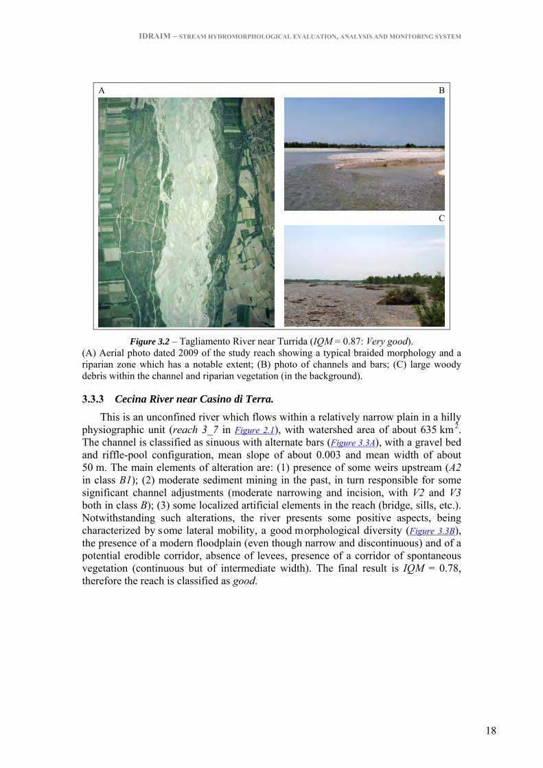
3.3.2 Tagliamento River near Turrida. In this reach, located in the Upper Friulian Plain, the river is unconfined since the
old terraces (one terrace is clearly visible in the right side of Figure 3.2A) are far apart allowing a wide space for lateral mobility (more than 3 km). The river displays a braided morphology and has the following characteristics: the bed is mainly made up of gravels; channel width ranges from 800 m to 1,000 m; average channel slope is 0.003. The elements which determine alterations of morphological quality are very few, due to a relatively low level of human intervention, if compared to other Italian rivers, in the drainage basin and in the alluvial plain. The elements of alteration are: (1) in-channel sediment removal, which occurred mainly in the 1970s and 1980s, and, likely, removal of large woody debris; (2) channel adjustments which have led to significant channel narrowing (about 50%, referring to channel width in the 1950s) and moderate incision (about 1.5 m). The reach has IQM = 0.87, and is classified as very good.
IDRAIM – STREAM HYDROMORPHOLOGICAL EVALUATION, ANALYSIS AND MONITORING SYSTEM
18
A
B
C
Figure 3.2 – Tagliamento River near Turrida (IQM = 0.87: Very good). (A) Aerial photo dated 2009 of the study reach showing a typical braided morphology and a riparian zone which has a notable extent; (B) photo of channels and bars; (C) large woody debris within the channel and riparian vegetation (in the background).
3.3.3 Cecina River near Casino di Terra. This is an unconfined river which flows within a relatively narrow plain in a hilly
physiographic unit (reach 3_7 in Figure 2.1), with watershed area of about 635 km 2. The channel is classified as sinuous with alternate bars (Figure 3.3A), with a gravel bed and riffle-pool configuration, mean slope of about 0.003 and mean width of about 50 m. The main elements of alteration are: (1) presence of some weirs upstream (A2 in class B1); (2) moderate sediment mining in the past, in turn responsible for some significant channel adjustments (moderate narrowing and incision, with V2 and V3 both in class B); (3) some localized artificial elements in the reach (bridge, sills, etc.). Notwithstanding such alterations, the river presents some positive aspects, being characterized by some lateral mobility, a good morphological diversity (Figure 3.3B), the presence of a modern floodplain (even though narrow and discontinuous) and of a potential erodible corridor, absence of levees, presence of a corridor of spontaneous vegetation (continuous but of intermediate width). The final result is IQM = 0.78, therefore the reach is classified as good.

IDRAIM – STREAM HYDROMORPHOLOGICAL EVALUATION, ANALYSIS AND MONITORING SYSTEM
19
A
B
Figure 3.3 – Cecina River near Casino di Terra (IQM = 0.78: Good). (A) Aerial photo dated 2006 of part of the reach highlighting the typical sinuous morphology with alternate bars; (B) detail of the reach showing the morphological variability associated with a diversification of forms and the presence of retreating banks (on the back).
3.3.4 Furkelbach (Furcia Torrent) in Val Pusteria. The Furkelbach (or Furcia) torrent is a left tributary of the Rienza River (Val
Pusteria, Provincia Autonoma di Bolzano), entirely belonging to a physiographic unit of “alpine mountain area”. Its drainage area is 23.4 km2. The analysed reach (length of 1.7 km, from 1,310 to 1,148 m a.s.l., with a mean bed slope of 9.5%) is a single-thread confined stream with a mean channel width of about 8 m . The Furkelbach represents a typical case of an alpine torrent strongly altered by hydraulic structures, the presence of an adjacent road which alters the hillslope – stream continuity, and maintenance interventions on r iparian vegetation. However, the geomorphic functionality results in being of an intermediate level. Regarding artificiality, the highest criticality is represented by the presence of 67 weirs in the reach (Figure 3.4A), with a resulting frequency of about 4 for each 100 m (therefore A4 is in class C with further 14 scores assigned to it because of the very high density). Furthermore, slightly upstream (400 m) there is a big open check dam (Figure 3.4B, A2 in class B1). Other artificiality elements include some bank protections (A6 in class B), and the relative removal and cutting of riparian vegetation and wood (A11 and A12 in class C). Summarising, IAM is equal to 0.54 and IQM to 0.46, meaning that the quality of the reach is poor.

IDRAIM – STREAM HYDROMORPHOLOGICAL EVALUATION, ANALYSIS AND MONITORING SYSTEM
20
A
B
Figure 3.4 – The Furkelbach (Furcia) Torrent in Val Pusteria (IQM = 0.46: Poor). (A) The reach analysed downstream: the influence of the several weirs on the channel morphology is evident from the fact that it does not present a natural channel bed configuration with cascades as would be expected for the given channel slope (9.5%), as well as the artificiality of riparian vegetation subject to periodic cutting, and the total absence of woody material within the channel; (B) the open check dam immediately upstream of the reach.
3.3.5 Panaro River near Vignola. This is an unconfined reach between Vignola and Savignano (length of about
2 km), along the apex of an alluvial fan (physiographic unit of high Apenninic plain), having a mean channel slope of 0.007, and a mean width of 96 m. It represents a case of very strong physical degradation, although the artificiality is not at maximum levels, demonstrated by drastic changes in the channel pattern and width (Figure 3.5A and Figure 3.5B), and of the channel bed (incision > 6 m), mainly related to past intensive mining activity and the reduction of upstream sediment supply. Therefore the channel changes indicators (V1, V2 and V3) result as having maximum scores. Other main critical points are represented by the presence of weirs upstream and in the reach (A2 in class B2 and A4 in class B), the absence of a modern floodplain (Figure 3.5C), the alteration of bed substrate with widespread clay outcrops (F10 in class C2) (Figure 3.5D), and the reduction of morphological diversity, in turn related to the strong incision. The final result is IQM = 0.40, therefore the reach is classified as poor.

IDRAIM – STREAM HYDROMORPHOLOGICAL EVALUATION, ANALYSIS AND MONITORING SYSTEM
21
A
B
C
D
Figure 3.5 – Panaro River near Vignola (IQM = 0.40: Poor). (A) Aerial photo dated 1954 showing a wide braided channel; (B) aerial photo dated 2003 highlighting the drastic narrowing and change in channel pattern (single thread); (C) detail of the reach showing high unstable banks and terraced surfaces deriving from the strong incision; (D) detail showing the clay outcropping on the channel bed and basal banks.
3.3.6 Arno River in Florence. This is an unconfined reach within a plain (physiographic unit of intermountain
plain), well representative of a large river crossing a densely urbanized area Figure 3.6A). The channel is classified as straight, with mean slope of 0.0018, a nd mean channel width of 115 m. The artificiality of the reach is very high, because of the continuous presence of lateral structures, and in part transversal, that prevent any kind of lateral and vertical dynamics (Figure 3.6B), compromising most of the morphological functionalities. Upstream longitudinal continuity is also altered due to the presence of dams and several weirs. The continuous presence of bank protection elements and levees in the reach entails the assignment of additional scores to the indicators A6 and A7, therefore the artificiality reaches the maximum score. The final result is IQM = 0.11, therefore the reach is classified as very poor.

IDRAIM – STREAM HYDROMORPHOLOGICAL EVALUATION, ANALYSIS AND MONITORING SYSTEM
22
A
B
Figure 3.6 – Arno River in Florence (IQM = 0.11: Very poor). (A) Satellite image dated 2007 showing how the reach crosses a highly urbanized area. (B) Detail showing the presence of bank protection elements (with the function of levees) and the homogeneity of cross section.
3.3.7 Gadria Torrent near Lasa. This is a left tributary of the Adige River, subject to very frequent channelized
debris flow, 1÷2 per year in average. The catchment (drainage area of about 14 km2) is very steep and subject to frequent surface landslides. The analyzed reach (2.2 km) crosses the Gadria alluvial fan, one of the biggest in Europe, and consequently presents the characteristics of an unconfined reach in a mountain physiographic context. The channel was channelized at the end of the 19th century, when a straight course with bed revetment was created (Figure 3.7), with the aim of conveying the debris flow down to the Adige River. Later, an open check dam was built just upstream to stop all the sediment. Geomorphological functionality is at the minimum for most of the indicators (except F1). The artificiality is high (class C) only for relatively few indicators. However, the continuous presence of bank protection elements, levees, and bed revetments entails the assignation of additional scores to indicators A6, A7 and A9, causing a maximum artificiality score. The resulting IQM is equal to 0.04 (very poor).
A
B
Figure 3.7 – Gadria Torrent near Lasa (IQM = 0.04: Very poor). (A) Aerial photo dated 2006 showing the alluvial fan crossed by the stream along the study reach. B) Detail showing the artificial configuration of the stream.

IDRAIM – STREAM HYDROMORPHOLOGICAL EVALUATION, ANALYSIS AND MONITORING SYSTEM
23
CHAPTER 4
MONITORING
Two monitoring methodologies can be identified:
(1) Non instrumental monitoring: this consists of periodically repeating the procedure for the assessment of the current morphological conditions. Besides a new field survey and updating the artificial elements, it possibly requires an analysis of new images to evaluate possible channel changes. This monitoring activity allows the verification of the conservation of the previous morphological state or of the evidence of recovery or further reduction of the morphological quality. It is a relatively rapid procedure which does not, however, allow a detailed analysis of the possible causes of alteration or trends of adjustment.
(2) Instrumental monitoring: this requires carrying out periodic field measurements (other than from remote sensing) to analyze in a more systematic way possible channel changes (i.e. channel width or bed elevation changes). This monitoring activity is obviously more onerous but can permit the more detailed analysis of the causes and trends of channel adjustments. A list of the natural morphological elements to monitor is shown in Table 4.1, while monitoring artificial elements corresponds to an updating of the data base of interventions.
For the WFD implementation, non instrumental monitoring is identified with the so called surveillance monitoring and is applied to a relatively high number of reaches in the watershed representative of different physiographic and morphologic conditions, while instrumental monitoring is identified with the operative or investigative monitoring, to be carried out for a limited number of reaches at risk or in particular cases.

IDRAIM – STREAM HYDROMORPHOLOGICAL EVALUATION, ANALYSIS AND MONITORING SYSTEM
24
Table 4.1 – Morphological aspects, parameters, methodologies, and spatial scale for Instrumental Monitoring.
MORPHOLOGICAL ELEMENT METHOD OF SURVEY AND RELATIVE SPATIAL SCALE STREAM TYPOLOGY
1.1 Discharge Hydrometric measurements on existing gauging stations All
1.2 Lateral extension and continuity of modern floodplain
Remote sensing (reach)
Only semi- unconfined channels
1.3 Length of retreating banks and rates of retreat
Remote sensing (reach)
Only semi- unconfined channels
2.1 Sinuosity index Remote sensing or field measurement (small channels) (reach) All
2.2 Braiding index - Remote sensing (reach) - Field measurement (site)
All excluding single thread
2.3 Anastomosing index - Remote sensing (reach) - Field measurement (site)
All excluding single thread
2.4 Bar and island sizes Remote sensing (reach) Only large channels
2.5 Morphological pattern - Remote sensing (reach) - Field measurement (site and/or
reach)
- Only large channels - All
2.6 Channel slope Survey of bed profile, possibly extended from site to reach All
3.1 Channel width - Remote sensing (reach) - Survey of cross-sections (site)
- Only large channels - All
3.2 Channel depth Survey of cross-sections (site) All 3.3 Width to depth ratio Survey of cross-sections (site) All
3.4 Bed-level changes Survey of bed profile extended from site to reach All
4.1 Grain size of bed sediment - Pebble counts (sedimentary unit) - Volumetric sample (sedimentary
unit)
- Wadable gravel-bed rivers
- Sandy and/or not wadable rivers
4.2 Bed structures: armouring ratio and clogging
- Qualitative evaluation (site) - Grain size analysis (sedimentary
unit) in case of high armouring
Only wadable gravel-bed rivers
4.3 In-channel large woody storage
- Field counting (site) - Remote sensing (site)
- Single thread rivers - Large wandering/
braided rivers

IDRAIM – STREAM HYDROMORPHOLOGICAL EVALUATION, ANALYSIS AND MONITORING SYSTEM
25
References
- AGENCES DE L’EAU (1998). SEQ Physique: A System for the Evaluation of the Physical Quality of Watercourses; Agences de l’Eau, 15 pp.
- BARTHOLDY J. & BILLI P. (2002). Morphodynamics of a pseudomeandering gravel bar reach. Geomorphology, 42, 293–310.
- BRICE J.C. (1984). Planform properties of meandering rivers. In River Meandering, Proceedings Conference on Rivers ’83 , Elliott CM (ed.). ASCE: New York; 1–15.
- BRIERLEY G.J. & FRYIRS K.A. (2005). Geomorphology and River Management. Applications of the River Styles Framework. Blackwell Publishing, 398 pp.
- BUFFAGNI A., ERBA S. & CIAMPITTIELLO M. (2005). Il rilevamento idromorfologici e degli habitat fluviali nel contesto della direttiva europea sulle acque (WFD): principi e schede di applicazione del metodo Caravaggio - Notiziario dei metodi analitici, 2, Istituto di Ricerca sulle Acque, CNR IRSA, 32–34.
- CEN (2002). A Guidance Standard for Assessing the Hydromorphological Features of Rivers. CEN – TC 230/WG 2/TG 5: N32
- CHANDESRIS A., MENGIN N., MALAVOI J.R., SOUCHON Y., PELLA H., WASSON J.G. (2008). Systeme Relationnel d’Audit de l’Hydromorphologie des Cours d’Eau. Principes et methodes, v3.1. Cemagref, Lyon Cedex, 81 pp.
- CHURCH M.A. (1992). Channel Morphology and Typology. In: P.Callow and Petts, G.E. (Eds), The Rivers Handbook, Oxford, Blackwell, 126 – 143.
- CLARKE S.J., BRUC-BURGESS L., AND WHARTON G. (2003). Linking form and function: towards an eco-hydromorphic approach to sustainable river restoration. Aquatic Conservation: Marine and Freshwater Ecosystems, 13, 439 – 450.
- ENVIRONMENT AGENCY (1998). River Geomorphology: a pr atical guide. Environment Agency, Guidance Note 18, National Centre for Risk Analysis and Options Appraisal, London, 56 pp.
- EUROPEAN COMMISSION (2000). Directive 2000/60 EC of the European Parliament and of the Council of 23 October 2000 establishing a f ramework for Community action in the field of water policy. Official Journal L 327, 22/12/2000, 73 pp.
- GURNELL A., TUBINO M., TOCKNER K. (2009). Linkages and feedbacks in highly dynamic alpine fluvial systems. Aquatic Science, 71(3), 251-252.
- ISPRA (2009). Implementazione della Direttiva 2000/60/CE - Analisi e valutazione degli aspetti idromorfologici:
- http://www.sintai.sinanet.apat.it/view/index.faces. - KAIL J., HERING D. (2009). The influence of adjacent stream reaches on the local
ecological status of Central European mountain streams. River Research and Applications, 25(5), 537-550.
- LENZI M.A., D’AGOSTINO V. & SONDA D. (2000). Ricostruzione morfologica e recupero ambientale dei torrenti.Criteri metodologici ed esecutivi. Editoriale Bios, 208 pp.
- LEOPOLD L.B. & WOLMAN M.G. (1957). River channel patterns: braided, meandering and straight. US.Geol.Surv., Prof.Paper, 282-B, 39-85.
- MAAS S., BROOKES A. (2009). Fluvial Geomorphology. In: Environment Agency, Fluvial Design Guide, FDG2, 3-1 - 3-20.
- MALAVOI J.R. & BRAVARD J.P. (2010). Elements d’hydromorphologie fluviale. ONEMA, Baume-Les-Dames, France, 224 pp.

IDRAIM – STREAM HYDROMORPHOLOGICAL EVALUATION, ANALYSIS AND MONITORING SYSTEM
26
- MONTGOMERY D.R. & BUFFINGTON J.M. (1997). Channel-reach morphology in mountain drainage basins. Geological Society of America Bulletin, 109 (5), 596-611.
- NARDINI A., SANSONI G., SCHIPANI I., CONTE G., GOLTARA A., BOZ B., BIZZI S., POLAZZO A., MONACI M. (2008). Problemi e limiti della Direttiva Quadro sulle Acque. Una proposta integrativa: FLEA (FLuvial Ecosystem Assessment). Biologia Ambientale, 22 (2), 3-18.
- NEWSON M.D., LARGE A.R.G. (2006). Natural rivers, hydromorphological quality and river restoration: a c hallenging new agenda for applied fluvial geomorphology. Earth Surface Processes and Landforms, 31, 1606-1624.
- OLLERO OJEDA A., BALLARÍN FERRER D., DÍAZ BEA E., MORA MUR D., SÁNCHEZ FABRE M., ACÍN NAVERAC V., ECHEVERRÍA ARNEDO M.T., GRANADO GARCÍA D., IBISATE GONZÁLEZ DE MATAUCO A., SÁNCHEZ GIL L., SÁNCHEZ GIL N. (2007). Un indice hydrogeomorfologico (IHG) para la evaluacion del estado ecologico de sistemas fluviales. Geographicalia, 52, 113-141.
- PALMER M.A., BERNHARDT E.S., ALLAN J.D., LAKE P.S., ALEXANDER G., BROOKS S., CARR J., CLAYTON S., DAHM C.N., SHAH J.F., GALAT D.L., LOSS S.G., GOODWIN P., HART D.D., HASSETT B., JENKINSON R., KONDOLF G.M., LAVE R., MEYER J.L., O’DONNELL T.K., PAGANO L. & SUDDUTH E. (2005). Standard for ecologically successful river restoration. Journal of Applied Ecology, 42: 208-217.
- RAVEN P.J., FOX P.J.A., EVERARD M., HOLMES N.T.H., DAWSON F.H. (1997). River Habitat Survey: a new system for classifying rivers according to their habitat quality. In: Boon P.J. and Howell D.L. (Eds), Freshwater quality: Defining the indefinable? The Stationary Office, Edinburgh, 215-234.
- RAVEN P.J., HOLMES N.T.H., DAWSON F.H., FOX P.J.A., EVERARD M., FOZZARD I.R., ROUEN K.J. (1998). River Habitat Quality. The physical character of rivers and streams in the UK and Isle of Man. River Habitat Survey Report No. 2, 34 pp.
- RINALDI M. (2003). Recent channel adjustments in alluvial rivers of Tuscany, Central Italy. Earth Surface Processes and Landforms, 28 (6), 587-608.
- RINALDI M. (2008). Schede di rilevamento geomorfologico di alvei fluviali. Il Quaternario, 21(1B), 353-366.
- RINALDI M., SURIAN N., COMITI F., BUSSETTINI M. (2010). The morphological quality index (IQM) for stream evaluation and hydromorphological classification. Italian Journal of Engineering Geology and Environment. In press.
- RINALDI M., TERUGGI L.B., SIMONCINI C., NARDI L. (2008). Dinamica recente ed attuale di alvei fluviali: alcuni casi di studio dell’Appennino Settentrionale. Il Quaternario, 21(1B), 291-302.
- SCHUMM S.A. (1977). The Fluvial System. Wiley, New York, 338 pp. - SEAR D.A., NEWSON M.D. & THORNE C.R. (2003). Guidebook of Applied Fluvial
Geomorphology. Defra/Environment Agency Flood and Coastal Defence R&D Programme, R&D Technical Report FD1914, 233 pp.
- SILIGARDI et al. (2007) – IFF2007, Indice di Funzionalità Fluviale. Nuova versione del metodo revisionata e aggiornata. Manuale APAT 2007, 321 pp.
- SURIAN N. & RINALDI M. (2003). Morphological response to river engineering and management in alluvial channels in Italy. Geomorphology, 50 (4), 307-326.
- SURIAN N., RINALDI M., PELLEGRINI L., AUDISIO C., MARAGA F., TERUGGI L., TURITTO O. & ZILIANI L. (2009a). Channel adjustments in northern and central Italy over the last 200 years. In: James L.A., Rathburn S.L., Whittecar G.R. (eds.), Management and Restoration of Fluvial Systems with Broad Historical Changes and Human Impacts, Geological Society of America Special Paper 451, pp. 83-95.

IDRAIM – STREAM HYDROMORPHOLOGICAL EVALUATION, ANALYSIS AND MONITORING SYSTEM
27
- SURIAN N., RINALDI M., PELLEGRINI L., con il contributo di Audisio C., Barbero G., Cibien L., Cisotto A., Duci G., Maraga F., Nardi L., Simoncini C., Teruggi L.B., Turitto O., Ziliani L. (2009b). Linee guida per l’analisi geomorfologica degli alvei fluviali e delle loro tendenze evolutive. CLEUP, Padova, 78 pp.
- THORNE C.R. (1997). Channel types and m orphological classification. In: C.R. Thorne, R.D. Hey and M.D. Newson (Eds), Applied Fluvial Geomorphology for River Engineering and Management, Wiley, 175-222.
- VOGEL R.M. (2011). Hydromorphology: scientific and engineering challenges for 2050. In: Grayman W.M, Loucks, D.P, and Saito L. (Eds), Environment and Water Resources in 2050: A Vision and Path Forward, Emerging and Innovative Technology Committee, EWRI. ASCE Press, 2011, in press.
- WOHL E.E. (2000). Mountain rivers. American Geophysical Union, Washington DC, 320 pp.
- WYŻGA B., AMIROWICZ A., RADECKI-PAWLIK A., ZAWIEJSKA J. (2009). Hydromorphological conditions, potential fish habitats and the fish community in a mountain river subjected to variable human impacts, the Czarny Dunajec, Polish Carpathians. River Research and Applications, 25(5), 517-536.

IDRAIM – STREAM HYDROMORPHOLOGICAL EVALUATION, ANALYSIS AND MONITORING SYSTEM
i
APPENDIX 1
GUIDE TO THE COMPILATION OF THE EVALUATION FORMS

IDRAIM – STREAM HYDROMORPHOLOGICAL EVALUATION, ANALYSIS AND MONITORING SYSTEM
1
GUIDE TO THE COMPILATION OF THE EVALUATION FORMS
In this section, a definition of each indicator and an extended version of the possible answers is reported. Furthermore, for each indicator the following information is reported:
• Spatial scale (longitudinal and lateral); • Type of measurements (e.g. field survey, remote sensing, or other sources of information); • Typology (confined, semiconfined or unconfined); • Range of application (for those indicators that are not applied in specific cases).
GENERALITY AND INITIAL SEGMENTATION The first part of the evaluation form is dedicated to a series of general information, including the
date of the field survey (although the complete compilation of the evaluation form requires a preparation phase and a conclusion phase of the measurements after the field visit), and the name(s) of the operators. Then the name of the catchment and of the stream/river is indicated. The upstream and downstream limits of the reach must be clearly defined (e.g. name of a tributary, if this represents a limit, or planimetric coordinates). It follows the identification code of the segment and reach, and the stream length.
The following part is dedicated to all information and measurements made during the four steps of the general setting and initial segmentation. During STEP 1, the physiographic setting (area and unit) is specified. During STEP 2, the details for the classification of confinement are provided. Note that, as for all the indexes reported in this section, the operator can report the precise value of the index, or only specify the class (e.g. > 90%, 10÷90% or < 10% for the confinement degree). STEP 3 is dedicated to channel morphology. First of all, the name of the image (aerial photo or satellite image) used as a reference for all observations aimed at morphological classification is indicated. Then, all the indexes and other information are reported, including the mean bed slope and the mean channel width along the reach. In STEP 4, information regarding other elements for reach delimitation is reported. Finally, it is possible to report additional available data or information which are useful for the assessment (e.g. sediment sizes and discharges).
GEOMORPHOLOGICAL FUNCTIONALITY
CONTINUITY
F1: Longitudinal continuity in sediment and wood flux DEFINITION
This is the evaluation of whether the longitudinal continuity of sediment and wood solids is altered by human structures that intercept or create obstacles to their flow (discontinuities due to natural factors, such as rock outcroppings, lakes or landslide dams are not considered).
SPATIAL SCALE LONGITUDINAL: Site/Reach LATERAL: Channel MEASUREMENTS: Remote sensing and field survey
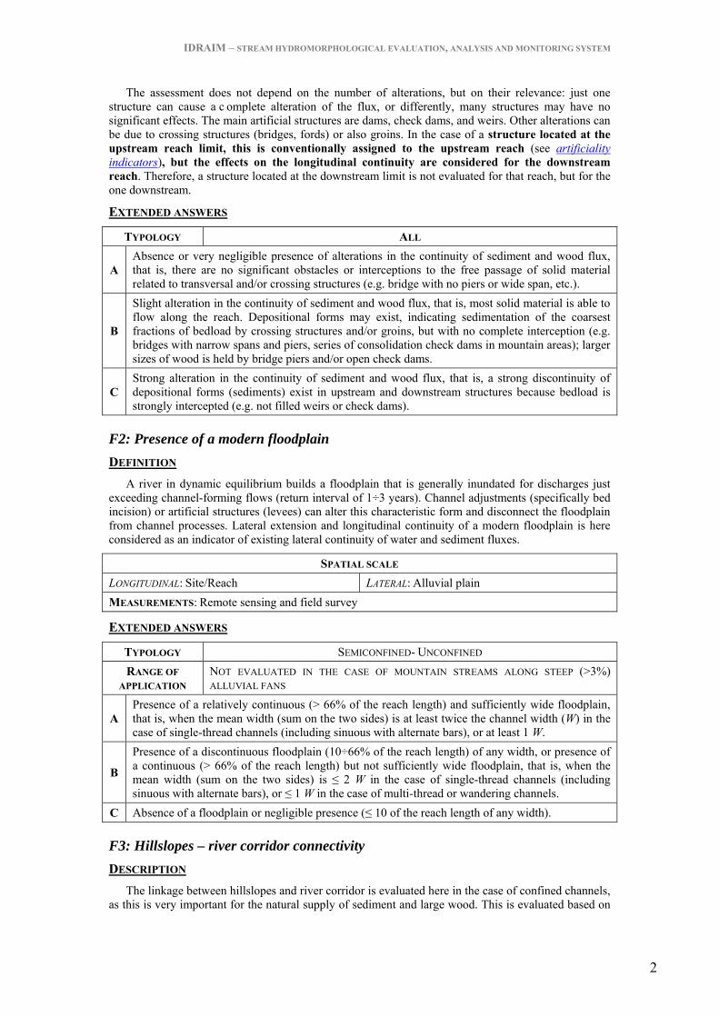
IDRAIM – STREAM HYDROMORPHOLOGICAL EVALUATION, ANALYSIS AND MONITORING SYSTEM
2
The assessment does not depend on the number of alterations, but on their relevance: just one structure can cause a c omplete alteration of the flux, or differently, many structures may have no significant effects. The main artificial structures are dams, check dams, and weirs. Other alterations can be due to crossing structures (bridges, fords) or also groins. In the case of a structure located at the upstream reach limit, this is conventionally assigned to the upstream reach (see artificiality indicators), but the effects on the longitudinal continuity are considered for the downstream reach. Therefore, a structure located at the downstream limit is not evaluated for that reach, but for the one downstream.
EXTENDED ANSWERS
TYPOLOGY ALL
A Absence or very negligible presence of alterations in the continuity of sediment and wood flux, that is, there are no significant obstacles or interceptions to the free passage of solid material related to transversal and/or crossing structures (e.g. bridge with no piers or wide span, etc.).
B
Slight alteration in the continuity of sediment and wood flux, that is, most solid material is able to flow along the reach. Depositional forms may exist, indicating sedimentation of the coarsest fractions of bedload by crossing structures and/or groins, but with no complete interception (e.g. bridges with narrow spans and piers, series of consolidation check dams in mountain areas); larger sizes of wood is held by bridge piers and/or open check dams.
C Strong alteration in the continuity of sediment and wood flux, that is, a strong discontinuity of depositional forms (sediments) exist in upstream and downstream structures because bedload is strongly intercepted (e.g. not filled weirs or check dams).
F2: Presence of a modern floodplain DEFINITION
A river in dynamic equilibrium builds a floodplain that is generally inundated for discharges just exceeding channel-forming flows (return interval of 1÷3 years). Channel adjustments (specifically bed incision) or artificial structures (levees) can alter this characteristic form and disconnect the floodplain from channel processes. Lateral extension and longitudinal continuity of a modern floodplain is here considered as an indicator of existing lateral continuity of water and sediment fluxes.
SPATIAL SCALE LONGITUDINAL: Site/Reach LATERAL: Alluvial plain MEASUREMENTS: Remote sensing and field survey
EXTENDED ANSWERS
TYPOLOGY SEMICONFINED- UNCONFINED RANGE OF
APPLICATION NOT EVALUATED IN THE CASE OF MOUNTAIN STREAMS ALONG STEEP (>3%) ALLUVIAL FANS
A Presence of a relatively continuous (> 66% of the reach length) and sufficiently wide floodplain, that is, when the mean width (sum on the two sides) is at least twice the channel width (W) in the case of single-thread channels (including sinuous with alternate bars), or at least 1 W.
B
Presence of a discontinuous floodplain (10÷66% of the reach length) of any width, or presence of a continuous (> 66% of the reach length) but not sufficiently wide floodplain, that is, when the mean width (sum on the two sides) is ≤ 2 W in the case of single-thread channels (including sinuous with alternate bars), or ≤ 1 W in the case of multi-thread or wandering channels.
C Absence of a floodplain or negligible presence (≤ 10 of the reach length of any width).
F3: Hillslopes – river corridor connectivity DESCRIPTION
The linkage between hillslopes and river corridor is evaluated here in the case of confined channels, as this is very important for the natural supply of sediment and large wood. This is evaluated based on

IDRAIM – STREAM HYDROMORPHOLOGICAL EVALUATION, ANALYSIS AND MONITORING SYSTEM
3
the presence and percentage on the reach length of elements of disconnection (e.g. roads) in a strip conventionally 50 m wide for each river side.
SPATIAL SCALE LONGITUDINAL: Reach LATERAL: Plain/adjacent hillslopes MEASUREMENTS: Remote sensing and field survey
EXTENDED ANSWERS
TYPOLOGY CONFINED
A A full connectivity exists between hillslopes and river corridor (channel and floodplain), extending for most of the reach (> 90%).
B The connectivity between hillslopes and river corridor exists for a significant portion of the reach (33÷90%).
C The connectivity between hillslopes and river corridor exists for a small portion of the reach (≤ 33%).
F4: Processes of bank retreat DEFINITION
Bank erosion is a key process contributing to sediment supply and recovery. An evaluation is necessary as to whether bank erosion processes occur as expected for a given river typology, or if there is a significant difference, such as absence due to widespread bank control, or excessive bank failures due to instability of the system (e.g. due to incision).
SPATIAL SCALE LONGITUDINAL: Site/Reach LATERAL: Channel MEASUREMENTS: Remote sensing and/or field survey
EXTENDED ANSWERS
TYPOLOGY SEMICONFINED- UNCONFINED RANGE OF
APPLICATION NOT EVALUATED IN THE CASE OF STRAIGHT – SINUOUS CHANNELS WITH LOW ENERGY (LOWLAND PLAIN, LOW BED-SLOPE AND/OR BEDLOAD)
A Frequent retreating riverbanks: bank erosion is observed in a number of points along the reach. Erosion is concentrated on the outer bank of bends (single-thread sinuous – meandering channels) and/or in front of bars (braided or wandering channels).
B Retreating riverbanks less frequent than expected for a given channel morphology, because impeded by protective elements and/or scarce channel dynamics: erosion is observed locally and for limited lengths.
C
Complete absence or negligible presence (very localized erosion) of retreating riverbanks due to excessive human control (bank protection) and/or absent channel dynamics (except for reaches at low energy: see range of application). Or presence of unstable banks for mass movements (due to excessive bank height) very common along a predominant portion of the reach (very unstable reaches because of bed incision).
F5: Presence of a potentially erodible corridor DEFINITION
The presence of a potentially erodible corridor is nowadays widely recognised as a positive attribute of rivers. A rapid assessment is performed by evaluating whether the width and longitudinal continuity of areas without relevant human structures or infrastructures (e.g. houses, roads) are within or out of given ranges.

IDRAIM – STREAM HYDROMORPHOLOGICAL EVALUATION, ANALYSIS AND MONITORING SYSTEM
4
SPATIAL SCALE LONGITUDINAL: Reach LATERAL: Alluvial plain MEASUREMENTS: Remote sensing
EXTENDED ANSWERS
TYPOLOGY SEMICONFINED OR UNCONFINED
A
Presence of a relatively continuous (> 66% of the reach length) and sufficiently wide potentially erodible corridor (EC), that is, the mean width (sum of the two sides) is at least twice the channel width (W) in the case of single-thread channels (including sinuous with alternate bars), or at least 1 W.
B
Presence of a potentially erodible corridor (EC) with medium continuity (33÷66% of the reach length) and width , that is, the mean width (sum of the two sides) is at least twice the channel width (W) in case of single-thread channels (including sinuous with alternate bars), or at least 1 W; or a potentially EC for > 66% of the reach length but not sufficiently wide.
C Presence of a potentially erodible corridor (EC) of any width but with low continuity (≤ 33% of the reach length).
MORPHOLOGY
F6: Bed configuration – valley slope DEFINITION
This indicator evaluates whether or not the presence of transversal structures has altered the expected bed configuration (cascade, step-pool, plane bed, riffle-pool, dune-ripple) based on the mean bed slope of the reach. In fact, a strong correlation exists between bed slope and configuration, that is, for increasing slopes the following order of forms is expected: dune-ripples, riffle-pool, plane bed, step-pool / cascade. These morphologies have ecological implications as each of them is characterized by a mosaic of typical habitats.
The existence of a transversal structure can cause an artificial lowering of the local energy slope and therefore a possible alteration of the bed configuration and, consequently, of the associated habitats. This indicator intends therefore to evaluate the magnitude of change caused by transversal structures.
SPATIAL SCALE LONGITUDINAL: Site/Reach LATERAL: Channel MEASUREMENTS: Field survey and Remote sensing
This indicator is evaluated only in the case of single thread confined channels (in case of multi-thread or wandering channels, it is substituted by F7, therefore F6 and F7 are necessarily alternatives).
The operator should determine the mean valley slope along the reach (based on the longitudinal bed profile already used during the phase of segmentation), and then define the expected bed form according to Table 1.
Table 1 – Relations between range of bed slope and expected bed forms.
BED FORMS DOMINANT GRAIN SIZE RANGE OF BED SLOPE Dune-ripple Sand and fine gravel ≤ 0.2 Riffle-pool Gravel and cobbles < 2 Plane bad Cobbles and gravel 1÷4
Step-pool/cascade Boulders and cobbles > 3

IDRAIM – STREAM HYDROMORPHOLOGICAL EVALUATION, ANALYSIS AND MONITORING SYSTEM
5
EXTENDED ANSWERS
TYPOLOGY CONFINED
RANGE OF APPLICATION
APPLIED TO SINGLE-THREAD CHANNELS. NOT EVALUATED IN THE CASE OF CONFINED WITH BEDROCK, AND IN THE CASE OF DEEP STREAMS WHEN IT IS NOT POSSIBLE TO OBSERVE THE BED CONFIGURATION
A
Bed forms consistent with the mean valley slope: bed configuration corresponds to that expected, based on the mean valley slope along the reach (Table 1). Included in this class are also the morphologies imposed by natural factors (e.g. log steps, landslides, etc.) which locally can determine unexpected bed forms (e.g. riffles in a steep reach, etc.).
B
Bed forms not consistent with the mean valley slope: bed configuration does not correspond to that expected, based on the mean valley slope along the reach (Table 1), because of presence of transversal structures (dams, check dams, weirs, sills, ramps, etc.). Included in this class are also the morphologies imposed by natural factors (e.g. log steps, landslides, etc.) which locally can determine unexpected bed forms (e.g. riffles in a steep reach, etc.).
C
Complete alteration of bed forms: all cases in which the bed is completely artificial (revetments) or the distance between transversal structures is so close as to not allow the creation of natural bed forms. Generally this is the case when the scour pool downstream of each structure extends for a length > 40÷50% of the distance between two successive structures.
F7: Forms and processes typical of the channel pattern DEFINITION
The aim of this indicator is to qualitatively assess whether the active processes and resultant forms expected for a given morphological type are present along the reach. For example, a channelized reach classified as meandering based on its planimetric configuration may not exhibit typical processes of that morphology.
SPATIAL SCALE LONGITUDINAL: Site/Reach LATERALE: Channel MEASUREMENTS: Field survey and/or remote sensing
EXTENDED ANSWERS
TYPOLOGY ALL RANGE OF
APPLICATION IN THE CASE OF CONFINED CHANNELS IT IS APPLIED ONLY TO MULTI-THREAD OR WANDERING MORPHOLOGIES
A
Absence or negligible presence (< 5% of the reach length) of alteration of the natural heterogeneity of forms expected for that river type. Braided: typical presence of a multi-thread configuration with several bifurcations and longitudinal bars, frequent pioneer islands and some mature islands. Wandering: typical alternate side bars, chute cut-offs, low-water channel highly sinuous and relatively narrow within the bankfull channel, localized braiding phenomena, presence of pioneer islands and in some cases mature islands. Sinuous with alternate bars: typical alternate side bars, chute cut-offs, low-water channel highly sinuous and relatively narrow within the bankfull channel, succession of riffles and pools (except in sand-bed rivers). Sinuous or meandering with bars: side or point bars, frequent erosion of outer banks (particularly in meandering channels), possible chute cut-offs, succession of riffles and pools (except in sand-bed rivers). Straight, sinuous or meandering at low energy: they do not necessarily exhibit a significant heterogeneity of forms: they can be stable and with no bars.
B Alteration for a limited portion of the reach (≤ 33% of the reach length) of the natural heterogeneity of forms expected for that river type.
C Consistent alteration for a significant portion of the reach (> 33% of the reach length) of the natural heterogeneity of forms expected for that river type.

IDRAIM – STREAM HYDROMORPHOLOGICAL EVALUATION, ANALYSIS AND MONITORING SYSTEM
6
F8: Presence of typical fluvial forms in the alluvial plain DEFINITION
This indicator is applied only to lowland meandering rivers, and accounts for the presence or not of typical fluvial forms (such as oxbow lakes, secondary channels, etc.) that are normally expected to exist in the alluvial plain.
SPATIAL SCALE LONGITUDINAL: Reach LATERAL: Alluvial plain MEASUREMENTS: Remote sensing
EXTENDED ANSWERS
TYPOLOGY SEMICONFINED OR UNCONFINED RANGE OF
APPLICATION IT IS APPLIED ONLY TO MEANDERING CHANNELS (NOW OR IN THE PAST) OF LOWLAND PHYSIOGRAPHIC UNITS
A Presence of natural fluvial forms in the alluvial plain related to the meandering channel dynamics (oxbow lakes, secondary channels, traces of abandoned meanders, wet zones, etc.).
B Presence of traces of fluvial forms in the alluvial plain (abandoned after the 1950s), now not in connection with the present channel but with possible reactivation by recovery interventions.
C Complete absence of fluvial forms in the alluvial plain related to the meandering channel dynamics.
F9: Variability of the cross-section DEFINITION
This indicator accounts for the variability and heterogeneity of forms and surfaces in cross-section expected for a given channel morphology, and the percentage of the reach with altered conditions is evaluated.
SPATIAL SCALE LONGITUDINAL: Site/Reach LATERAL: Channel MEASUREMENTS: Field survey and remote sensing
EXTENDED ANSWERS
TYPOLOGY CONFINED
A
Absence or localized presence (≤ 5% of the reach length) of alteration of the cross-section natural heterogeneity along the entire reach: a natural variability of the cross section (channel width and depth) exists – in relation to the presence of bars, vegetation, boulders, influence of hillslopes – and/or presence of frequent zones of flow separation adjacent to the banks. Or presence of alteration only on one side for ≤ 10 % of the total length of the banks (that is, the sum of both banks) (except for large channels, i.e. W > 30 m).
B
Presence of alteration of the cross-section natural heterogeneity for a limited portion of the reach (≤ 33% of the reach length): a natural variability of the cross section (channel width and depth) exists for >66% of the reach length, and/or occasional zones of flow separation. Or presence of alteration only on one side for ≤ 66 % of the total length of the banks (that is, the sum of both banks) (except for large channels, i.e. W > 30 m).
C
Presence of alteration of the cross-section natural heterogeneity for a significant portion of the reach (> 33% of the reach length): the cross section is nearly homogeneous for a significant portion of the reach (> 33%), and/or absence of zones of flow separation adjacent to the banks. Or presence of alteration only on one side for > 66 % of the total length of the banks (that is, the sum of both banks) (except for large channels, i.e. W > 30 m).

IDRAIM – STREAM HYDROMORPHOLOGICAL EVALUATION, ANALYSIS AND MONITORING SYSTEM
7
TYPOLOGY SEMICONFINED OR UNCONFINED
RANGE OF APPLICATION
NOT EVALUATED IN THE CASE OF STRAIGHT, SINUOUS OR MEANDERING CHANNELS WITH NATURAL ABSENCE OF BARS (LOWLAND RIVERS, LOW GRADIENTS AND/OR LOW BEDLOAD) (NATURAL CROSS-SECTION HOMOGENEITY)
A
Absence or localized presence (≤5% of the reach length) of alteration of the cross-section natural heterogeneity (width and depth) along the reach: a natural variability of channel width exists, in relation to the presence of bars and curvatures, combined with a natural altimetric variability in cross-section, in relation to the presence of side or point bars, eventual high bars, islands (pioneer or mature), secondary channels, and natural banks. Or presence of alteration only on one side for ≤ 10 % of the total length of the banks (that is, the sum of both banks) (except for large channels, i.e. W > 30 m).
B
Presence of alteration of the cross-section natural heterogeneity (width and depth) for a limited portion of the reach (≤ 33% of the reach length); or presence of alteration only on one side for ≤ 66 % of the total length of the banks (that is, the sum of both banks) (except for large channels, i.e. W > 30 m).
C Presence of alteration of the cross-section natural heterogeneity (width and depth) for a significant portion of the reach (> 33%); or presence of alteration only on one side for > 66 % of the total length of the banks (that is, the sum of both banks) (except for large channels, i.e. W > 30 m).
F10: Structure of the channel bed DEFINITION
This indicator takes into account possible alterations of the bed sediment, such as armouring, clogging, substrate outcrops or bed revetments.
SPATIAL SCALE
LONGITUDINAL: Site LATERAL: Channel MEASUREMENTS: Field survey
There are differences between the cases of confined channels and semi- or unconfined channels. In the former case, armouring is not considered, as normally confined channels with a mobile bed (the indicator is not applied in the case of bedrock) have a naturally strong heterogeneity of sediments. Therefore, armouring is assessed only in the case of semiconfined and unconfined channels.
A field evaluation is necessary for this indicator. The evaluation is concentrated at the scale of the representative site, although additional checks at other sites of the reach can be considered. A quantitative assessment of armouring requires sediment sampling and measurements of the surface layer and sub-layer, which are beyond the scope of this procedure. Therefore armouring, as well as clogging, are visually assessed. Only cases of evident and widespread clogging or armouring are taken into consideration . For example, the presence of clogging can be normal in particular situations (e.g. in the pools or along a stream close to hillslopes composed of clay), but it is considered an alteration when it is evident and present in various portions of the site. Two cases are considered: (1) where armouring or clogging is well marked and evident in various portions of the site, but not widespread along most of it (class B); (2) where there is well marked and evident armouring or clogging along the entire site (> 90% of the site length) (class C1).
In the case of semiconfined and unconfined channels, an additional element of alteration is bedrock outcropping. However, it requires careful evaluation: it is to be considered as alteration only when it is evidently related to bed-incision, that is, in alluvial reaches with a mobile bed far from the hillslopes, while it has to be excluded in those cases with hillslopes not far from the channel and where they can represent natural outcrops.

IDRAIM – STREAM HYDROMORPHOLOGICAL EVALUATION, ANALYSIS AND MONITORING SYSTEM
8
EXTENDED ANSWERS
TYPOLOGY CONFINED RANGE OF
APPLICATION NOT EVALUATED FOR BEDROCK OR SAND-BED RIVERS, OR FOR DEEP RIVERS WHEN IT IS NOT POSSIBLE TO OBSERVE THE CHANNEL BED
A Natural heterogeneity of bed sediments in relation to the different sedimentary units (steps, pools, riffles, etc.), with absence of or localized situations of clogging.
B Evident clogging in various portions of the site. C1 Evident and widespread clogging (> 90% of the site length). C2 Widespread substrate alteration by bed revetments (any type) (> 33% of the reach length).
TYPOLOGY SEMICONFINED OR UNCONFINED RANGE OF
APPLICATION NOT EVALUATED FOR BEDROCK OR SAND-BED RIVERS, OR FOR DEEP RIVERS WHEN IT IS NOT POSSIBLE TO OBSERVE THE CHANNEL BED
A Natural heterogeneity of bed sediments in relation to the different sedimentary units (bars, channel bed, pools, riffles, etc.) and also within the same unit, with absence of or localized situations of armouring and/or clogging.
B Evident armouring or clogging in various portions of the site.
C1 Evident and widespread (> 90%) armouring or clogging, or occasional substrate outcrops (≤ 33% of the reach length) due to incision of the alluvial substrate.
C2 Widespread substrate outcrops (> 33% of the reach length) due to incision of the alluvial substrate or widespread substrate alteration by bed revetments (any type) (> 33% of the reach length).
F11: Presence of in-channel large wood DEFINITION
An evaluation is carried out to determine whether altered conditions exist compared to the expected presence of large wood along the reach. Large wood includes trees, trunks, branches, butts having a length > 1 m and diameter > 10 c m. This material has several effects on ge omorphic-hydraulic processes, and has various implications on ecological processes (habitat diversity, input of organic matter, etc.). On the other hand, it is widely recognized that this material represents an important hydraulic hazard factor.
SPATIAL SCALE LONGITUDINAL: Site LATERAL: Channel MEASUREMENTS: Field survey
The indicator is evaluated for both types of streams (confined and semi- unconfined). Given the high spatial and temporal variability of the quantity of wood material, it is not possible to define precise values for the number of woody elements to observe. Reaches are evaluated as altered when the presence of wood is extremely limited or completely absent (approximately < 5 elements every 100 m of channel length).
The operator will carry out the evaluation based on field observations at the spatial scale of the site. In some cases (large channels), remote sensing images can be useful. The evaluation area includes the channel (including islands) and the banks (wood on the floodplain is not considered). Additional rules accounting for particular situations of natural scarcity of wood are reported at the end of the Extended answers. Lastly, the indicator is not evaluated for reaches above the tree-line or where riparian vegetation is completely absent due to natural factors in the reach and in the upstream reaches.

IDRAIM – STREAM HYDROMORPHOLOGICAL EVALUATION, ANALYSIS AND MONITORING SYSTEM
9
EXTENDED ANSWERS
TYPOLOGY ALL RANGE OF
APPLICATION NOT EVALUATED ABOVE THE TREE-LINE AND IN STREAMS WITH NATURAL ABSENCE OF RIPARIAN VEGETATION
A Significant presence of large woody debris: the presence of large woody debris (plants, trunks, branches, butts) within the channel and/or on the banks.
C Very limited presence or absence of large woody debris: when a significant presence of large woody debris is not observed within the channel (including islands) and/or on the banks.
1) In confined channels: in the case of bankfull width > mean tree height, mean bankfull depth > mean tree diameter, and in the absence of significant obstacles (e.g. large boulders), class A is assigned (reach of wood transport: natural absence).
2) In semiconfined - unconfined: in the case of the absence of bars (lowland plain), the relative abundance of woody debris has to be evaluated near the banks.
VEGETATION IN THE FLUVIAL CORRIDOR
The following two indicators (F12 and F13) concern the vegetation existing in the river corridor that includes the adjacent areas extending from the channel to the hillslopes, and that is functional to the normal geomorphic processes (flow resistance, bank stabilization, wood recruitment, sediment trapping, etc.). No ecological considerations are made on the type of vegetation (i.e. invasive species, etc.). Plantations with an industrial purpose (e.g. populus, eucalyptus, paulownia, etc.) are considered as partially functional, as they are characterized by markedly lower densities and consequently do not fully carry out their geomorphic functions. Therefore, lower scores are assigned to this type of vegetation. Other plantations of woody vegetation (e.g. olive tree, grape vine, apple tree, etc.) are not considered as functional.
It is necessary that the vegetation is connected with the channel, in relation to the geomorphic processes considered here (erosion, flooding). Therefore, vegetation external to artificial levees is completely excluded, whereas vegetation external to bank protections is taken into consideration as it may interfere with a number of processes (flow resistance, flooding, wood supply, etc.). In the case of confined channels, roads interrupt this connection (similarly to the artificial levees for unconfined channels).
Indicators F12 and F13 are not applied above the natural tree-line, which is quite variable on Italian territory (approximately around 1,800 ÷2,300 m a.s.l.). In many cases, grazing has lowered this limit: in such a cas e, it is considered as an alteration. Lastly, the indicators are not evaluated in cases of particular climatic conditions (e.g. along “fiumare” in Mediterranean regions) where woody vegetation is not able to colonize the river corridor.
F12: Width of functional vegetation in the fluvial corridor DEFINITION
This indicator assesses the width of functional vegetation directly connected with the channel. In the case of confined channels, the functional width is evaluated up to a distance of 50 m from each bank, excluding the cases of near vertical hillslopes or the presence of landslides, where woody vegetation may be naturally absent. In the case of semiconfined and unconfined channels, the width of functional vegetation is evaluated as a function of channel width.
SPATIAL SCALE LONGITUDINAL: Reach LATERAL: Alluvial plain (semiconfined /
unconfined); Plain/ adjacent hillslopes (confined) MEASUREMENTS: Remote sensing
The evaluation is carried out by remote sensing and GIS analysis, by delimitating the woody/shrub vegetation in the river corridor, up to the limit of 50 m in the case of confined channels. Note that any islands present within the channel are included in the computation.

IDRAIM – STREAM HYDROMORPHOLOGICAL EVALUATION, ANALYSIS AND MONITORING SYSTEM
10
EXTENDED ANSWERS
TYPOLOGY ALL RANGE OF
APPLICATION NOT EVALUATED ABOVE THE TREE-LINE AND IN STREAMS WITH NATURAL ABSENCE OF RIPARIAN VEGETATION
A
High width of functional vegetation, that is: - for CONFINED CHANNELS, functional vegetation occupying > 90% of adjacent plain (if present)
and hillslopes (50 m from each bank, excluding portions with rock or landslides). The functional vegetation includes either woody species (with significant cover, i.e. > 33% of the width) and spontaneous shrub species.
- for SEMI- UNCONFINED CHANNELS, functional vegetation with a total width (sum of the two sides) of at least nLa, where La is the channel width, n = 2 for single-thread channels, n = 1 for multi-thread or wandering channels. The functional width includes either woody and shrub species, with a significant presence of the former (> 33% of the width occupied by woody vegetation).
B
Medium width of functional vegetation, that is: - for CONFINED CHANNELS, functional vegetation occupying 33÷90% of adjacent plain (if
present) and hillslopes (50 m from each bank, excluding portions with rock or landslides). Functional vegetation includes either woody species (with significant cover, i.e. > 33% of the functional width) and spontaneous shrub species.
Or, as in case A, but with largely prevailing shrub species (i.e. woody vegetation ≤ 33% of the functional width). - for SEMI- UNCONFINED CHANNELS, functional vegetation with a total width (sum of the two
sides) between 0.5 La and nLa, where La is the channel width, n = 2 for single-thread channels, n = 1 for multi-thread or wandering channels.
Or, as in case A, but where the width > nLa is determined by the presence of partially functional species (e.g. artificial plantations of populus), or in the case of largely prevailing shrub species (i.e. woody vegetation ≤ 33% of the functional width).
C
Limited width of functional vegetation, that is: - for CONFINED CHANNELS, functional vegetation ≤ 33% of adjacent plain (if present) and
hillslopes (50 m from each bank, excluding portions with rock or landslides). Functional vegetation includes either woody species (with significant cover, i.e. > 33% of the functional width) and spontaneous shrub species.
Or, as in case B, but with largely prevailing shrub species (i.e. woody vegetation ≤ 33% of the functional width). - for SEMI- UNCONFINED CHANNELS, functional vegetation with a total width (sum of the two
sides) ≤ 0.5 La (any channel typology), where La is the channel width. Or, as in case B, but where the width > 0.5 La is determined by the presence of partially functional species (e.g. artificial plantations of populus), or in the case of largely prevailing shrub species (i.e. woody vegetation ≤ 33% of the functional width).
F13: Linear extension of functional vegetation along the banks DEFINITION
This indicator evaluates the longitudinal continuity of functional vegetation along the banks, as a percentage of the length covered by vegetation against the total length of the reach (both banks). Rows of trees for ornamental scopes are considered as partially functional, and they are assimilated to industrial plantations (see previous indicator).
SPATIAL SCALE LONGITUDINAL: Reach LATERAL: Banks MEASUREMENTS: Remote sensing
The evaluation is carried out by remote sensing and GIS analysis. The same delimitation of woody/shrub vegetation in the river corridor carried out for F12 will be used, measuring the length (sum of the two banks) at direct contact with the channel. Then, this length will be compared to the

IDRAIM – STREAM HYDROMORPHOLOGICAL EVALUATION, ANALYSIS AND MONITORING SYSTEM
11
total potential length (sum of the two banks) where functional vegetation can be present (i.e. excluding portions of banks with rock or landslides). In case of difficulties in the interpretation of remote images (confined channels), a check at the scale of the site may be required (e.g. to identify banks with rock).
EXTENDED ANSWERS
TYPOLOGY ALL RANGE OF
APPLICATION NOT EVALUATED ABOVE THE TREE-LINE OR IN STREAMS WITH NATURAL ABSENCE OF RIPARIAN VEGETATION
A Linear extension of functional vegetation for a length > 90% of maximum available length (i.e. sum of both banks excluding those in rock or landslides). Presence of either woody species (> 33% of the length of functional vegetation) or spontaneous shrub species.
B
Linear extension of functional vegetation for a length of 33÷90% of maximum available length (i.e. sum of both banks excluding those in rock or landslides). Or, as in case A, but the extension > 90% is determined by the presence of partially functional species (e.g. industrial plantations of populus or rows for ornamental purposes), or in the case of shrub species largely prevailing (woody species < 33% of the length of the functional vegetation).
C
Linear extension of functional vegetation for a length of ≤ 33% of maximum available length (i.e. sum of both banks excluding those in rock or landslides). Or, as in case B, but the extension > 33% is determined by the presence of partially functional species (e.g. industrial plantations of populus or rows for ornamental purposes), or in the case of shrub species largely prevailing (woody species < 33% of the length of the functional vegetation).
ARTIFICIALITY
UPSTREAM ALTERATION OF LONGITUDINAL CONTINUITY
The first four indicators of artificiality consider the alteration of the driving variables for channel morphology, which are water discharges and sediment transport. It is useful to conceptually separate the alterations of the same variables occurring upstream and within the reach. Indicators A1 and A2 are the only two concerned with the conditions existing upstream (catchment location scale) of the analyzed reach, while the next two indicators A3 and A4 concern the alterations of the same characteristics, but within the reach.
For this purpose, in the case of a structure (e.g. a dam) located at the limit between two reaches (e.g. between an upstream reach n1 and a downstream reach n2), conventionally the structure is assigned to the one upstream. In other terms, the effects of the structure are considered as alterations in the reach (by the indicators A3 and A4) for the upstream reach n1, while they are accounted as upstream alterations (by the indicators A1 and A2) for the downstream reach n2.
A1: Upstream alteration of discharges DEFINITION
This indicator evaluates the possible alterations of channel-forming discharges and/or discharges with higher return intervals due to interventions at the catchment scale (dams, diversions, spillways, retention basins, etc.).
SPATIAL SCALE LONGITUDINAL: Catchment LATERAL: Alluvial plain MEASUREMENTS: Census of interventions, remote sensing
Identification of existing interventions having effects on discharges can be carried out by a census of interventions and remote sensing. This indicator also requires data and information about the management of the structures (e.g. dams) and their effects on discharges. This can be achieved from agencies in charge of the river management. Note that this type of information and hydrologic data collected at the catchment scale is an essential part of the Phase 1 (general setting-up), and this knowledge is then used for all the reaches of a given catchment.
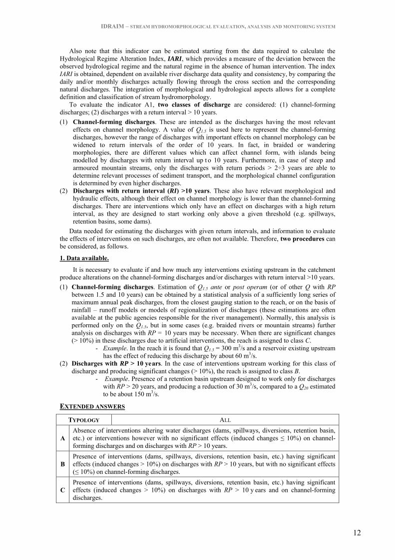
IDRAIM – STREAM HYDROMORPHOLOGICAL EVALUATION, ANALYSIS AND MONITORING SYSTEM
12
Also note that this indicator can be estimated starting from the data required to calculate the Hydrological Regime Alteration Index, IARI, which provides a measure of the deviation between the observed hydrological regime and the natural regime in the absence of human intervention. The index IARI is obtained, dependent on available river discharge data quality and consistency, by comparing the daily and/or monthly discharges actually flowing through the cross section and the corresponding natural discharges. The integration of morphological and hydrological aspects allows for a complete definition and classification of stream hydromorphology.
To evaluate the indicator A1, two classes of discharge are considered: (1) channel-forming discharges; (2) discharges with a return interval > 10 years. (1) Channel-forming discharges. These are intended as the discharges having the most relevant
effects on channel morphology. A value of Q1.5 is used here to represent the channel-forming discharges, however the range of discharges with important effects on channel morphology can be widened to return intervals of the order of 10 years. In fact, in braided or wandering morphologies, there are different values which can affect channel form, with islands being modelled by discharges with return interval up t o 10 years. Furthermore, in case of steep and armoured mountain streams, only the discharges with return periods > 2÷3 years are able to determine relevant processes of sediment transport, and the morphological channel configuration is determined by even higher discharges.
(2) Discharges with return interval (RI) >10 years. These also have relevant morphological and hydraulic effects, although their effect on channel morphology is lower than the channel-forming discharges. There are interventions which only have an effect on discharges with a high return interval, as they are designed to start working only above a given threshold (e.g. spillways, retention basins, some dams).
Data needed for estimating the discharges with given return intervals, and information to evaluate the effects of interventions on such discharges, are often not available. Therefore, two procedures can be considered, as follows.
1. Data available.
It is necessary to evaluate if and how much any interventions existing upstream in the catchment produce alterations on the channel-forming discharges and/or discharges with return interval >10 years. (1) Channel-forming discharges. Estimation of Q1.5 ante or post operam (or of other Q with RP
between 1.5 and 10 years) can be obtained by a statistical analysis of a sufficiently long series of maximum annual peak discharges, from the closest gauging station to the reach, or on the basis of rainfall – runoff models or models of regionalization of discharges (these estimations are often available at the public agencies responsible for the river management). Normally, this analysis is performed only on the Q1.5, but in some cases (e.g. braided rivers or mountain streams) further analysis on discharges with RP = 10 years may be necessary. When there are significant changes (> 10%) in these discharges due to artificial interventions, the reach is assigned to class C.
- Example. In the reach it is found that Q1.5 = 300 m3/s and a reservoir existing upstream has the effect of reducing this discharge by about 60 m3/s.
(2) Discharges with RP > 10 years. In the case of interventions upstream working for this class of discharge and producing significant changes (> 10%), the reach is assigned to class B.
- Example. Presence of a retention basin upstream designed to work only for discharges with RP > 20 years, and producing a reduction of 30 m3/s, compared to a Q20 estimated to be about 150 m3/s.
EXTENDED ANSWERS
TYPOLOGY ALL
A Absence of interventions altering water discharges (dams, spillways, diversions, retention basin, etc.) or interventions however with no significant effects (induced changes ≤ 10%) on channel-forming discharges and on discharges with RP > 10 years.
B Presence of interventions (dams, spillways, diversions, retention basin, etc.) having significant effects (induced changes > 10%) on discharges with RP > 10 years, but with no significant effects (≤ 10%) on channel-forming discharges.
C Presence of interventions (dams, spillways, diversions, retention basin, etc.) having significant effects (induced changes > 10%) on discharges with RP > 10 y ears and on channel-forming discharges.
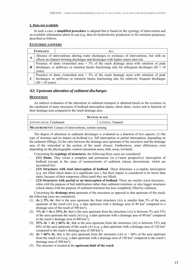
IDRAIM – STREAM HYDROMORPHOLOGICAL EVALUATION, ANALYSIS AND MONITORING SYSTEM
13
2. Data not available
In such a case, a simplified procedure is adopted that is based on the typology of intervention and on available information about its use (e.g. dam for hydroelectric production or for retention purposes), described as follows.
EXTENDED ANSWERS
TYPOLOGY ALL
A Absence of interventions altering water discharges or existence of interventions, but with no effects on channel-forming discharges and discharges with higher return intervals.
B Presence of dams (watershed area > 5% of the reach drainage area) with retention of peak discharges, or spillways or retention basins functioning only for infrequent discharges (RI > 10 years).
C Presence of dams (watershed area > 5% of the reach drainage area) with retention of peak discharges, or spillways or retention basins functioning also for relatively frequent discharges (RI < 10 years).
A2: Upstream alteration of sediment discharges DEFINITION
An indirect evaluation of the alterations in sediment transport is obtained based on the existence in the catchment of main structures of bedload interception (dams, check dams, weirs) and in function of their drainage area compared to the reach drainage area.
SPATIAL SCALE LONGITUDINAL: Catchment LATERAL: Channel MEASUREMENTS: Census of interventions, remote sensing
The degree of alteration in sediment discharges is evaluated as a function of two aspects: (1) the type of structure and its impact on bedload (i.e. full interception or partial interception, depending on the sediment filling); (2) the ratio between the drainage area upstream of the structures and the drainage area of the watershed at the section of the reach closure. Furthermore, some differences exist depending on the physiographic context (mountain areas, hilly areas, lowland).
Concerning the typology of structures, the following three cases are considered: - (T1) Dams. They create a complete and permanent (in a f uture perspective) interception of
bedload (except in the cases of measurements of sediment release downstream, which are accounted for).
- (T2) Structures with total interception of bedload. These determine a co mplete interception (e.g. not filled check dams of a significant size ), but their impact is considered to be lower than dams, because of their temporary effect (until they are filled).
- (T3) Structures with partial or no interception of bedload. These are smaller sized structures , often with the purpose of bed stabilization rather than sediment retention, or also bigger structures (check dams) with the purpose of sediment retention but now completely filled by sediment.
Concerning the drainage area upstream of the structures as opposed to that upstream of the reach, the following cases are considered: (1) As ≤ 5% Ar, that is the area upstream the from structures (As) is smaller than 5% of the area
upstream of the reach (Ar) (e.g. a dam upstream with a drainage area of 40 km2 compared to a drainage area of the reach of 500 km2);
(2) 5% Ar < As ≤ 33% Ar, that is the area upstream from the structures (As) is between 5% and 33% of the area upstream the reach (Ar) (e.g. a dam upstream with a drainage area of 40 km2 compared to the reach’s drainage area of 400 km2);
(3) 33% Ar < As ≤ 66% Ar, that is the area upstream from the structures (As) is between 33% and 66% of the area upstream of the reach (Ar) (e.g. a dam upstream with a drainage area of 120 km2 compared to the reach’s drainage area of 200 km2);
(4) As > 66% Ar, that is the area upstream from the structures (As) is > 66% of the area upstream from the reach (Ar) (e.g. a dam upstream with a drainage area of 150 km2 compared to the reach’s drainage area of 200 km2);
(5) The structure is located at the upstream limit of the reach.

IDRAIM – STREAM HYDROMORPHOLOGICAL EVALUATION, ANALYSIS AND MONITORING SYSTEM
14
The differences depending on the physiographic context are described as follows.
1. Mountain areas.
Structures included in the category T2 are check dams with total sediment retention (retention check dams: usually of large dimensions). Usually these structures are characterized by a s mall reservoir immediately upstream. Included in this category are also abstraction weirs of relevant size (in the order of various meters), which are not filled, and which have the effect of a temporary complete interception (until filling) of bedload.
Structures included in the category T3 can be identified with filled retention check dams, open check dams, and consolidation check dams. The latter are considered only when they are a long sequence of stepped check dams, determining the stabilization of the longitudinal bed profile. The drainage area is referred to the check dam furthest downstream. Therefore, isolated consolidation check dams that are unable to significantly reduce the upstream sediment supply are not considered. Assignation to the alteration class as a function of typology and drainage areas is reported in Table 2.
Table 2 – Definition of classes in mountain areas. As/Ar
TYPOLOGY 5÷33% 33÷66% > 66% UPSTREAM
LIMIT
(T1) Dams B1 B2 C1 C2
(T2) Check dams with total sediment retention A B1 B2 B2
(T3)
Filled or open check dams or sequence of consolidation check dams A A B1 B1
2. Hilly and lowland areas.
Structures included in the category T2 can be identified with consolidation check dams or abstraction weirs of relevant size (in the order of several meters), which are not filled, and which have the effect of temporary complete interception (until filling) of bedload.
Structures in the category T3 include consolidation check dams or abstraction weirs, but of a smaller size, or of a bigger size but filled with sediment. Assignation to the alteration class as a function of typology and drainage areas is reported in Table 3. Table 3 – Definition of classes in hilly or lowland areas.
As/Ar TYPOLOGY
5÷33% 33÷66% > 66% UPSTREAM LIMIT
(T1) Dams B1 B2 C1 C2 (T2) Consolidation check dams or abstraction weirs (big in size) with complete interception
A B1 B2 B2
(T3) Consolidation check dams or abstraction weirs with partial or no interception (or small in size)
A B1 B1 B1
Measures of sediment release or removal. In the case of measures of sediment release downstream from a dam (or other structure), the
score is reduced according to the following rules (in any physiographic context): (1) Measures allowing for the flux of all bedload downstream (complete by-pass): two classes lower
are assigned (e.g. from C2 to B2, or from B1 to A). (2) Measures allowing for a high but not total bedload flux downstream: a class lower is assigned
(e.g. from C2 to C1). Vice versa, if the maintenance agency in charge of a structure carries out a periodic sediment
removal upstream from a check dam (that is not released downstream) in order to prevent it from filling completely, the structure is considered as causing a complete interception of bedload (T2).
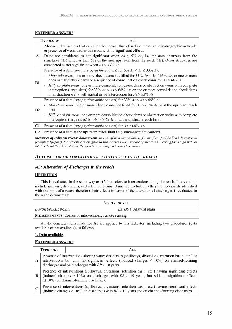
IDRAIM – STREAM HYDROMORPHOLOGICAL EVALUATION, ANALYSIS AND MONITORING SYSTEM
15
EXTENDED ANSWERS
TYPOLOGY ALL
A
Absence of structures that can alter the normal flux of sediment along the hydrographic network, or presence of weirs and/or dams but with no significant effects. Dams are considered as not significant when As ≤ 5% Ar, i.e. the area upstream from the structures (As) is lower than 5% of the area upstream from the reach (Ar). Other structures are considered as not significant when As ≤ 33% Ar.
B1
Presence of a dam (any physiographic context) for 5% Ar < As ≤ 33% Ar. - Mountain areas: one or more check dams not filled for 33% Ar < As ≤ 66% Ar, or one or more
open or filled check dams or a sequence of consolidation check dams for As > 66% Ar. - Hilly or plain areas: one or more consolidation check dams or abstraction weirs with complete
interception (large sizes) for 33% Ar < As ≤ 66% Ar, or one or more consolidation check dams or abstraction weirs with partial or no interception for As > 33% Ar.
B2
Presence of a dam (any physiographic context) for 33% Ar < As ≤ 66% Ar. - Mountain areas: one or more check dams not filled for As > 66% Ar or at the upstream reach
limit. - Hilly or plain areas: one or more consolidation check dams or abstraction weirs with complete
interception (large sizes) for As > 66% Ar or at the upstream reach limit. C1 Presence of a dam (any physiographic context) for As > 66% Ar. C2 Presence of a dam at the upstream reach limit (any physiographic context). Measures of sediment release downstream: in case of measures allowing for the flux of all bedload downstream (complete by-pass), the structure is assigned to two classes lower. in case of measures allowing for a high but not total bedload flux downstream, the structure is assigned to one class lower.
ALTERATION OF LONGITUDINAL CONTINUITY IN THE REACH
A3: Alteration of discharges in the reach DEFINITION
This is evaluated in the same way as A1, but refers to interventions along the reach. Interventions include spillway, diversions, and retention basins. Dams are excluded as they are necessarily identified with the limit of a reach, therefore their effects in terms of the alteration of discharges is evaluated in the reach downstream
SPATIAL SCALE LONGITUDINAL: Reach LATERAL: Alluvial plain MEASUREMENTS: Census of interventions, remote sensing
All the considerations made for A1 are applied to this indicator, including two procedures (data available or not available), as follows.
1. Data available.
EXTENDED ANSWERS
TYPOLOGY ALL
A Absence of interventions altering water discharges (spillways, diversions, retention basin, etc.) or interventions but with no significant effects (induced changes ≤ 10%) on channel-forming discharges and on discharges with RP > 10 years.
B Presence of interventions (spillways, diversions, retention basin, etc.) having significant effects (induced changes > 10%) on discharges with RP > 10 years, but with no significant effects (≤ 10%) on channel-forming discharges.
C Presence of interventions (spillways, diversions, retention basin, etc.) having significant effects (induced changes > 10%) on discharges with RP > 10 years and on channel-forming discharges.

IDRAIM – STREAM HYDROMORPHOLOGICAL EVALUATION, ANALYSIS AND MONITORING SYSTEM
16
2. Data not available.
EXTENDED ANSWERS
TYPOLOGY ALL
A Absence of interventions altering water discharges or existence of interventions, but with no effects on channel-forming discharges and discharges with higher return intervals.
B Presence of spillways, diversions or retention basins functioning only for infrequent discharges (RP > 10 years).
C Presence of spillways, diversions or retention basins functioning also for relatively frequent discharges (RP < 10 years).
A4: Alteration of sediment transport in the reach DEFINITION
This is based on the typology and frequency of structures intercepting bedload in the reach (check dams, weirs, diversion structures, etc.) or other structures causing its alteration (e.g. retention basins, dam downstream).
SPATIAL SCALE LONGITUDINAL: Reach LATERAL: Channel MEASUREMENTS: Census of interventions, Remote sensing, Field survey
In the case of a dam located at the downstream limit of the reach, as previously explained, its effects in terms of bedload interceptions are considered in the downstream reach by the indicator A2. However, the dam also alters the normal bedload flux for the portion of the reach immediately upstream from the structure (class C), by decreasing flow velocity and inducing sedimentation. If the artificial reservoir due to the dam is of a relevant size, it will not be subject to the assessment procedure (because the stream will have completely changed its original characteristics). Relevant size is normally intended to be equivalent to the spatial scale of a site (i.e. length not lower than 10 times the channel width). For reservoirs of a smaller size, they are included within the stream reach.
EXTENDED ANSWERS
TYPOLOGY ALL
A
Absence of any type of structures altering sediment discharges: there are no structures in the reach aimed to intercept sediment and wood (check dams, abstraction weirs, etc.) or which cause an alteration of sediment discharges (retention basins, dam downstream) although not designed for this purpose.
B
- Mountain areas (confined channels, or semi- unconfined steep channels, e.g. along alluvial fans): consolidation check dams with relatively low density (≤ 1 every 200 m on average in the reach) and/or one or more open check dams.
- Hilly – plain areas: one or more consolidation check dam and/or abstraction weirs (≤ 1 every 1000 m on average in the reach).
C
- Mountain areas (confined channels, or semi- unconfined steep channels, e.g. along alluvial fans): consolidation check dams with relatively low density (>1 every 200 m on average in the reach) and/or one or more check dams.
- Hilly – plain areas: one or more consolidation check dam and/or abstraction weir (>1 every 1000 m on average in the reach) and/or presence of a dam.
And/or artificial reservoir at the downstream reach limit (any physiographic context).
If the total density of transversal structures, including bed sills and ramps (see A9) is very high, i.e. > 1 every 100 m in mountain areas, or >1 every 500 m in hilly – plain areas, add 12.

IDRAIM – STREAM HYDROMORPHOLOGICAL EVALUATION, ANALYSIS AND MONITORING SYSTEM
17
A5: Crossing structures DEFINITION
This accounts for the presence and frequency of crossing structures, including bridges, fords, and culverts. Only bridges which interfere with the fluvial corridor are considered, that is, those bridges with some artificial element (piers or abutment) in the channel or adjacent plain, or potentially interfering with water fluxes although for exceptional flood events only. Bridges that are completely unrelated to the fluvial corridor are not counted (e.g. a viaduct crossing a valley markedly higher than the channel and with piers and/or abutments standing directly on hi llslopes). Regarding fords, only those with fixed crossing structures are accounted for here (i.e. dirt roads are not considered). Finally, the cases where streams cross urban areas underground are considered as culverts.
SPATIAL SCALE LONGITUDINAL: Reach LATERAL: Channel MEASUREMENTS: Remote sensing, topographic maps, field survey
EXTENDED ANSWERS
TYPOLOGY ALL A Absence of crossing structures (bridges, fords culverts). B Presence of some crossing structures (≤ 1 every 1000 m on average in the reach). C Presence of many crossing structures (> 1 every 1000 m on average in the reach).
ALTERATION OF LATERAL CONTINUITY
A6: Bank protections DEFINITION
Various types of bank protection are considered, including walls, gabions, groynes, and bioengineering bank stabilizations. The indicator is based on the percentage of protected banks over the total length (sum of both banks).
SPATIAL SCALE LONGITUDINAL: Reach LATERAL: Banks MEASUREMENTS: Census of interventions, remote sensing, field survey
Only bank protections along the bank lines (which are the limits of the bankfull channel) or in the close surroundings are considered: bank protections built in past periods, at present far from the channel and therefore having no immediate effects on channel mobility are not assessed (they may be considered in the indicator F5, having the effect of limiting the erodible corridor).
A particular case is that of the groynes. Similarly to the previous rule, only groynes in contact or within the channel are considered. In the latter case, an evaluation of the greater size between the groyne width and the protruding length is obtained (generally from aerial photos).
EXTENDED ANSWERS
TYPOLOGY ALL
A Absence or localized presence of bank protections, i.e. for a length ≤ 5% total length of the banks (sum of both banks).
B Presence of protections for ≤ 33% total length of the banks (sum of both banks). C Presence of protections for > 33% total length of the banks (sum of both banks). In the case of bank protections along most of the reach (i.e. >80% of total length of the banks) add 12.

IDRAIM – STREAM HYDROMORPHOLOGICAL EVALUATION, ANALYSIS AND MONITORING SYSTEM
18
A7: Artificial levees DEFINITION
This indicator accounts for the presence of artificial levees (or embankments). It is based on their longitudinal continuity and distance from the channel.
SPATIAL SCALE LONGITUDINAL: Reach LATERAL: Alluvial plain MEASUREMENTS: Remote sensing, topographic maps, field survey
Regarding the length, the percentage of the artificial levee’s length over the total length of the banks is considered (similarly to the previous indicator) though, in this case, the length of banks directly in contact with hillslopes is excluded. Regarding the distance, three possible cases are considered: (1) “distant” (set-back embankments): in case of distance > of the mean channel width (W); (2) “close”: in case of distance ≤ W; (3) “in contact”: when they are immediately in contact with the top of the bank, or maximum at a distance of the same order of magnitude as the bank height. Selection of the class is made according to the extended answers and Table 4. Note that the calculation is made separately for the two river sides: e.g. in the case of a left bank with 100% in contact and a right bank with 20% in contact and 80% close, the total in the reach will be 60% in contact and 40% close.
In the case of two artificial levee systems, the distance will be referred to the levees closest to the channel.
Table 4 – Definition of classes as a function of the length of levees in contact and close (in % over the total length of both banks).
CLASS IN CONTACT + CLOSE
[%] IN CONTACT
[%] A 0÷10 0÷10
B 10÷90 0÷50
90÷100 0÷33
C 50÷90 50÷90
90÷100 33÷100
EXTENDED ANSWERS
TYPOLOGY SEMICONFINED OR UNCONFINED
A Levees absent or distant (i.e. distance > W) for any length, or localized presence of close levees and/or in contact (≤ 10% of the total length of the banks).
B
Close levees and/or levees in contact for > 10% of the total length of the banks, including the following cases: (a) levees in contact for ≤ 50% (independently from % of close levees); (b) if the total length of close levees plus those in contact is > 90%, then levees in contact must be ≤ 33% of the total length of the banks.
C Close levees or levees in contact not included in the previous class, that is: (a) levees in contact > 50% (independently by % of close levees); (b) total length close and in contact levees > 90%, with levees in contact > 33% of the total length of the banks.
In the case of artificial levees along most of the reach (i.e. > 80% of total length of the banks) add 12.
ALTERATION OF CHANNEL MORPHOLOGY AND/OR SUBSTRATE
A8: Artificial changes of river course DEFINITION
This indicator accounts for historical changes in the river course. It has to be remarked that this indicator does not require a historical research of channel changes, which would be out of the range of
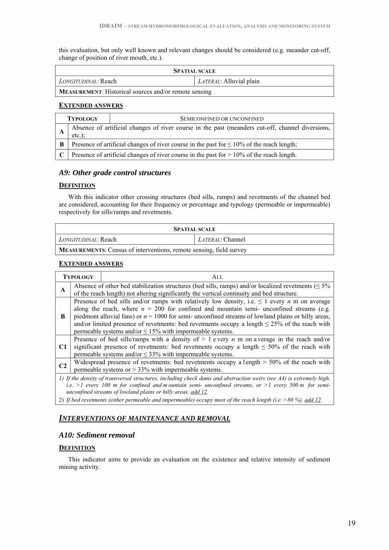
IDRAIM – STREAM HYDROMORPHOLOGICAL EVALUATION, ANALYSIS AND MONITORING SYSTEM
19
this evaluation, but only well known and relevant changes should be considered (e.g. meander cut-off, change of position of river mouth, etc.).
SPATIAL SCALE LONGITUDINAL: Reach LATERAL: Alluvial plain MEASUREMENT: Historical sources and/or remote sensing
EXTENDED ANSWERS
TYPOLOGY SEMICONFINED OR UNCONFINED
A Absence of artificial changes of river course in the past (meanders cut-off, channel diversions, etc.);
B Presence of artificial changes of river course in the past for ≤ 10% of the reach length; C Presence of artificial changes of river course in the past for > 10% of the reach length.
A9: Other grade control structures DEFINITION
With this indicator other crossing structures (bed sills, ramps) and revetments of the channel bed are considered, accounting for their frequency or percentage and typology (permeable or impermeable) respectively for sills/ramps and revetments.
SPATIAL SCALE LONGITUDINAL: Reach LATERAL: Channel MEASUREMENTS: Census of interventions, remote sensing, field survey
EXTENDED ANSWERS
TYPOLOGY ALL
A Absence of other bed stabilization structures (bed sills, ramps) and/or localized revetments (≤ 5% of the reach length) not altering significantly the vertical continuity and bed structure.
B
Presence of bed sills and/or ramps with relatively low density, i.e. ≤ 1 every n m on average along the reach, where n = 200 for confined and mountain semi- unconfined streams (e.g. piedmont alluvial fans) or n = 1000 for semi- unconfined streams of lowland plains or hilly areas, and/or limited presence of revetments: bed revetments occupy a length ≤ 25% of the reach with permeable systems and/or ≤ 15% with impermeable systems.
C1 Presence of bed sills/ramps with a density of > 1 e very n m on a verage in the reach and/or significant presence of revetments: bed revetments occupy a length ≤ 50% of the reach with permeable systems and/or ≤ 33% with impermeable systems.
C2 Widespread presence of revetments: bed revetments occupy a l ength > 50% of the reach with permeable systems or > 33% with impermeable systems.
1) If the density of transversal structures, including check dams and abstraction weirs (see A4) is extremely high, i.e. >1 every 100 m for confined and m ountain semi- unconfined streams, or >1 every 500 m for semi- unconfined streams of lowland plains or hilly areas, add 12.
2) If bed revetments (either permeable and impermeable) occupy most of the reach length (i.e. >80 %), add 12.
INTERVENTIONS OF MAINTENANCE AND REMOVAL
A10: Sediment removal DEFINITION
This indicator aims to provide an evaluation on the existence and relative intensity of sediment mining activity.

IDRAIM – STREAM HYDROMORPHOLOGICAL EVALUATION, ANALYSIS AND MONITORING SYSTEM
20
SPATIAL SCALE LONGITUDINAL: Reach LATERAL: Channel MEASUREMENTS: Census of interventions, remote sensing, field survey
The evaluation is slightly different from confined to semi- unconfined channels. In the former case, the investigated time period is exclusively that of the last 20 years (coherently with the following two indicators). The difference between the three classes is determined by the extension of any removal activity (absent, localized, widespread in the reach) during this time period. In the case of semi- and unconfined channels, two time periods are distinguished: (a) recent activity (last 20 years, as for confined channels); (b) past activity, extended to the 1950s (generally the decade of maximum activity in many areas of Italy). Regarding past activity, the indicator intends to provide a gross evaluation based on available information, since a quantification of extracted volumes is not possible. To this aim, three situations are considered: (1) absent; (2) moderate: when there is reliable information that the number of mining sites and the extracted volumes are significant (not negligible) but not high; (3) intense: when there is reliable information that the number of mining sites and the extracted volumes are particularly relevant. Indirect indicators of intense activity may be the number of mining sites nowadays or in the past (from aerial photos of the 1950s) in the surroundings of the river channel, intense incisions (see V3) that are attributable to mining activity, etc.
EXTENDED ANSWERS
TYPOLOGY CONFINED
A Evidence/reliable information of absent significant sediment removal activity during the last 20 years.
B Evidence/reliable information of significant but localized (only one site) sediment removal activity during the last 20 years.
C Evidence/reliable information of significant and widespread (more sites along the reach) sediment removal activity during the last 20 years.
TYPOLOGY SEMICONFINED OR UNCONFINED
A Absence of significant sediment removal activity either in the past (from 1950s) or during about the last 20 years.
B Moderate sediment removal activity in the past (from 1950s) but absent during about the last 20 years, or sediment removal activity during the last 20 years but absent in the past.
C Intense sediment removal activity in the past (from 1950s), or sediment removal activity during the last 20 years and moderate in the past (from 1950s).
A11: Wood removal DEFINITION
Wood removal can periodically be carried out by various public agencies in charge of river management and maintenance, usually in conjunction with cutting vegetation (see next indicator) and/or sediment removal. Typically, only larger sized woody material is removed, while fine woody debris (small trunks, branches) is left in the channel.
Wood removal is justifiable for safety reasons, however has a s ignificant impact on the fluvial system (e.g. reduction of hydrodynamic complexity, and therefore morphological and sedimentary diversity, with the disappearance of physical habitats for fishes and invertebrates).
SPATIAL SCALE LONGITUDINAL: Reach LATERAL: Channel and floodplain MEASUREMENTS: Information by public agencies
For this indicator, it is necessary to acquire information on total or partial wood removal during the last 20 years. This time interval is motivated both by the availability of information from public agencies, and by the natural capability of streams to once again achieve a sufficient quantity of wood from the banks, hillslopes and upstream reaches. In case of a lack of reliable information, the answer is B. Cases where F11 has not been applied are not evaluated.

IDRAIM – STREAM HYDROMORPHOLOGICAL EVALUATION, ANALYSIS AND MONITORING SYSTEM
21
EXTENDED ANSWERS
TYPOLOGY ALL RANGE OF
APPLICATION NOT EVALUATED ABOVE THE TREE-LINE AND IN STREAMS WITH NATURAL ABSENCE OF RIPARIAN VEGETATION
A Reliable information/evidence of the absence (or only in localized situations) of interventions for the removal of large wood (diameter > 10 cm and length > 1 m), at least in the last 20 years.
B
Reliable information/evidence of partial removal interventions during the last 20 years, that is, the removal of some elements only, often following flood events. Here are also included the cases of permission for removal by private citizens, even without any intervention from public agencies. Some woody material could be cut into elements < 1 m and left within the channel.
C Reliable information/evidence of removal interventions by public agencies during the last 20 years. Some woody material could be cut into elements < 1 m and left within the channel.
A12: Vegetation management DEFINITION
Similarly to the previous indicator, periodic interventions of vegetation cutting by public agencies are motivated by safety reasons, but they have various impacts on the natural processes related to riparian vegetation. In order to reduce such impacts, public agencies are recently oriented towards selective cutting (involving only the oldest trees) rather than a total removal. Note that grazing activity is here assimilated to vegetation cutting, as it prevents vegetation growth.
SPATIAL SCALE LONGITUDINAL: Site/Reach LATERAL: channel and portions of alluvial plain (semi-
unconfined) adjacent to the banks, or adjacent plain / hillslopes (confined)
MEASUREMENTS: Information from public agencies and field site check (presence of butts)
The operator has to collect information from the public agencies responsible for the vegetation management, and to observe in the field any possible evidence of past cuttings (i.e. presence of butts). The indicator is applied in the case of significant cutting activity (just a few plants cut along the reach are not considered). The investigated area corresponds to the width of functional vegetation identified with the indicator F12. For the same reasons as for the previous indicator, the time interval considered includes the last 20 years. The indicator is not applied for those reaches where F12 and F13 have not been evaluated.
EXTENDED ANSWERS
TYPOLOGY ALL RANGE OF
APPLICATION NOT EVALUATED ABOVE THE TREE-LINE AND IN STREAMS WITH NATURAL ABSENCE OF RIPARIAN VEGETATION
A Vegetation not subject to cutting interventions along the banks, or only affected by selective cutting within the areas external to the banks (alluvial plain for semi- unconfined, hillslopes for confined) during the last 20 years.
B Vegetation subject to interventions of selective cutting along the banks for any distance, or total cutting for a length < 50% of the reach; or total cuttings of any distance within the areas external to the banks (last 20 years).
C Vegetation subject to total cutting along the banks for a distance > 50% of the reach during the last 20 years.

IDRAIM – STREAM HYDROMORPHOLOGICAL EVALUATION, ANALYSIS AND MONITORING SYSTEM
22
CHANNEL CHANGES
V1: Changes in channel pattern DEFINITION
This indicator (and the following V2) is based on observation and analysis of aerial photos from the 1950s, compared to the most recent aerial photos. It evaluates whether there has been a change in the morphological type.
SPATIAL SCALE LONGITUDINAL: Reach LATERAL: Alluvial plain MEASUREMENTS: Remote sensing / GIS analysis
As for all the indicators of channel changes, it is applied only to large channels (width > 30 m, at present or in the 1950s). In Italy, aerial photos of the 1950s correspond to the flight IGM GAI covering the entire national territory, at a scale of about 1:33,000. In other countries, flights from the same period can be used. It applies both to confined and semi- unconfined, although some differences in the classes exist.
In the cases of semi- unconfined channels, the assignation to classes B or C depends on whether the change has occurred between similar morphologies (e.g. from meandering to sinuous) or between markedly different morphologies (e.g. from braided to sinuous), as defined in Table 5.
Table 5 – Classes for the different possible changes in channel morphologies. MORPHOLOGIES: ST = straight, S = sinuous, M = Meandering, SAB = Sinuous with Alternate Bars, W = Wandering, B = Braided, A = Anastomosed; = change in both directions. CLASS: B = change to a s imilar morphology; C = change to a markedly different morphology.
MORPHOLOGY CLASS MORPHOLOGY CLASS
ST S B M SAB B
ST M C M W C
ST SAB B M B C
ST W C M A B
ST B C SAB W B
ST A C SAB B C
S M B SAB A C
S SAB B W B B
S W C W A C
S B C B A C
S A B
EXTENDED ANSWERS
TYPOLOGY CONFINED RANGE OF
APPLICATION EVALUATED ONLY FOR LARGE CHANNELS (CHANNEL WIDTH > 30 m)
A Absence of changes of channel pattern from 1950s. B Change of channel pattern from 1950s.

IDRAIM – STREAM HYDROMORPHOLOGICAL EVALUATION, ANALYSIS AND MONITORING SYSTEM
23
V2: Changes in channel width DEFINITION
This indicator evaluates the occurrence and amount of changes in channel width from the 1950s to now.
SPATIAL SCALE LONGITUDINAL: Reach LATERAL: Alluvial plain MEASUREMENTS: Remote sensing / GIS analysis
As for the previous indicator, this indicator is applied only to large channels (width >30 m, at present or in the 1950s), both to confined and semi- unconfined, although some differences in the classes exist. In confined channels, only two classes are defined (in fact significant change in channel width would determine a change to an unconfined channel). The precise measurement of changes in channel width requires a GIS analysis, including the georectification of the different images, the digitizing of channel margins and the measurement of the channel width.
EXTENDED ANSWERS
TYPOLOGY CONFINED RANGE OF
APPLICATION EVALUATED ONLY FOR LARGE CHANNELS (CHANNEL WIDTH > 30 m)
A Absent or limited changes in channel width (≤ 15%) from 1950s. B Changes in channel width > 15% from 1950s.
TYPOLOGY SEMICONFINED OR UNCONFINED RANGE OF
APPLICATION EVALUATED ONLY FOR LARGE CHANNELS (CHANNEL WIDTH > 30 m)
A Absent or limited changes in channel width (≤ 15%) from 1950s. B Moderate changes in channel width (15÷35%) from 1950s. C Intense changes in channel width (> 35%) from 1950s.
TYPOLOGY SEMICONFINED OR UNCONFINED RANGE OF
APPLICATION EVALUATED ONLY FOR LARGE CHANNELS (CHANNEL WIDTH > 30 m)
A Absence of changes of channel pattern from 1950s. B Change to a similar channel pattern from 1950s (Table 5). C Change to a different channel pattern from 1950s (Table 5).

IDRAIM – STREAM HYDROMORPHOLOGICAL EVALUATION, ANALYSIS AND MONITORING SYSTEM
24
V3: Bed-level changes DEFINITION
Bed-level changes (incision or aggradation) are considered among the most relevant physical alterations affecting a n umber of processes (e.g. lateral connection with floodplain, alteration of in-channel habitats, etc.).
SPATIAL SCALE LONGITUDINAL: Reach LATERAL: Channel MEASUREMENTS: Data from cross-sections / longitudinal profiles, field survey
Similarly to V1 and V2, this indicator applies only to large channels (width > 30 m), both to confined and semi- unconfined with some differences. In the case of semi- unconfined channels, a class C2 is defined to account for cases of dramatic changes in bed elevation (> 6 m). Small-sized mountain streams may experience intense bed-level changes during exceptional flood events; however this indicator is not envisaged for such streams, coherently with the other two indicators of channel changes. This indicator is based on existing data (e.g. longitudinal profiles or cross sections), information from existing literature, and field evidence of bed-level changes. Differently from planimetric changes, in this case bed-level changes are referred to a wider temporal scale, i.e. about the last 100 years. This is due to the fact that, according to existing research on a national scale (e.g. SURIAN & RINALDI, 2003; SURIAN et al., 2009d), one or more phases of incision followed by a period of predominant aggradation or equilibrium occurred until about the end of the 19th century. This simplification allows a better utilization of field evidence, consisting of an evaluation of the differences in elevation between modern floodplain and recent terraces, the latter coinciding with the historical floodplain before the incision. In the cases of an absolute lack of data, field evidence or other sources of information, this indicator is omitted and is not included in the final score.
EXTENDED ANSWERS
TYPOLOGY CONFINED RANGE OF
APPLICATION EVALUATED ONLY FOR LARGE CHANNELS (CHANNEL WIDTH > 30 m)
A Negligible bed-level changes (≤ 0.5 m). B Limited or moderate bed-level changes (0.5÷3 m). C Intense bed-level changes (> 3 m).
TYPOLOGY SEMICONFINED OR UNCONFINED RANGE OF
APPLICATION EVALUATED ONLY FOR LARGE CHANNELS (CHANNEL WIDTH > 30 m)
A Negligible bed-level changes (≤ 0.5 m): bed elevation unchanged due to altimetric stability or to recovery by aggradation of a previous phase of incision (e.g. due to a weir).
B Limited or moderate bed-level changes (≤ 3 m). Incised channel: differences in elevation exist between new floodplain (if existing) and recent terraces, but in many cases not evident. Aggraded channel: bed-elevation higher than floodplain elevation.
C1
Intense bed-level changes (3÷6 m). Highly incised channel: very evident differences in elevation between new floodplain (if existing) and recent terraces, with the presence of evidence in several forms , including high and unstable banks, destabilization of transversal structures, exposed bridge piers, etc. Highly aggraded channel: marked differences in elevation between channel bed (much higher) and floodplain.
C2 Very intense bed-level changes (> 6 m). Exceptionally incised channel (e.g. following intense mining activity in the past). Usually, as well as the aforementioned evidence, data or reliable information about such an important incision will exist. Exceptionally aggraded channel.

IDRAIM – STREAM HYDROMORPHOLOGICAL EVALUATION, ANALYSIS AND MONITORING SYSTEM
25
SCORES For each indicator, the partial score relative to classes A, B or C must be circled in the apposite
column on t he right (first column on t he right side of the answers). In the following column, the progressive score is reported, so that the total deviation is immediately available at the end of the compilation of the evaluation form. In the last column on the right (inside the dotted lines), operator should express a degree of confidence in the answer, considering three possible cases: (1) High, (2) Medium, (3) Low. This can be indicated between class A and B, or between B and C. A simplified estimation of the overall uncertainty degree associated with the final evaluation can be obtained that is the range of variation of the final score. An e xample of the procedure can be visualized in the compiled evaluation form (see later).
On the bottom of the evaluation form, the Morphological Alteration Index and the Morphological Quality Index are calculated. The Morphological Alteration Index (IAM) is calculated as:
IAM = Stot / Smax
where Smax is the maximum possible deviation for the given stream typology (it corresponds to the sum of the class C scores for all the questions applicable to the study case).
The Morphological Quality Index (IQM) is expressed as:
IQM = 1 – IAM
SUB-INDEXES Given the structure divided into various aspects and categories, it is possible to calculate a series of
sub-indexes, that is, to sub-divide the two main indexes IAM and IQM into their components. This can be useful for identifying the negative and positive points of a reach.
The functionality, artificiality and channel changes sub-indexes (or “vertical sub-indexes”) can be obtained as follows:
1. FUNCTIONALITY
IAMF = SF tot/Smax IQMF = (SF max/Smax) – IAMF = (SF max – SF tot) / Smax Where SF tot = F1 +…+ F13 (sum of scores of applied F indicators); Max(SF tot) = Max(F1) +…+ Max(F13) (sum of maximum scores of all F indicators); Max(SA tot) = Max(A1) +…+ Max(A12) (sum of maximum scores of all A indicators); Max(SV tot) = Max(V1) +…+ Max(V3) (sum of maximum scores of all V indicators); Max(Stot) = Max(SF tot) + Max(SA tot) + Max(SV tot) (sum of maximum scores of all indicators); Sna(F) = sum of maximum scores of not applied F indicators; Sna = sum of maximum scores of not applied F, A, V indicator; SF max = Max(SF tot) – Sna(F); Smax = Max(Stot) – Sna.
2. ARTIFICIALITY
IAMA = SA tot/Smax IQMA = (SA max/Smax) – IAMA = (SA max – SA tot) / Smax Where:

IDRAIM – STREAM HYDROMORPHOLOGICAL EVALUATION, ANALYSIS AND MONITORING SYSTEM
26
SAtot = A1 +…+ A12 (sum of scores of applied A indicators); Max(SF tot) = Max(F1) +…+ Max(F13) (sum of maximum scores of all F indicators); Max(SA tot) = Max(A1) +…+ Max(A12) (sum of maximum scores of all A indicators); Max(SV tot) = Max(V1) +…+ Max(V3) (sum of maximum scores of all V indicators); Max(Stot) = Max(SF tot) + Max(SA tot) + Max(SV tot) (sum of maximum scores of all indicators); Sna(A) = sum of maximum scores of not applied A indicators; Sna = sum of maximum scores of not applied F, A, V indicator; SA max= Max(SA tot) – Sna(A); Smax = Max(Stot) – Sna.
3. CHANNEL CHANGES IAMV = SV tot/Smax IQMV = (SVmax/Smax) – IAMV = (SV max – SV tot) / Smax Where: SVtot = V1 +…+ V3 (sum of scores of applied V indicators); Max(SF tot) = Max(F1) +…+ Max(F13) (sum of maximum scores of all F indicators); Max(SA tot) = Max(A1) +…+ Max(A12) (sum of maximum scores of all A indicators); Max(SV tot) = Max(V1) +…+ Max(V3) (sum of maximum scores of all V indicators); Max(Stot) = Max(SF tot) + Max(SA tot) + Max(SV tot) (sum of maximum scores of all indicators); Sna(V) = sum of maximum scores of not applied V indicators; Sna = sum of maximum scores of not applied F, A, V indicator; SV max= Max(SV tot) – Sna(V); Smax = Max(Stot) – Sna.
To make the analysis more effective, the sub-indexes can be related to the maximum value that they can reach for a given category (functionality, artificiality, channel changes). For this purpose, the overall value of IAM and IQM is divided in the part relative to each category as follows:
1. FUNCTIONALITY
IAMF max = IQMF max = SF max/Smax
2. ARTIFICIALITY
IAMA max = IQMA max = SA max/Smax
3. CHANNEL CHANGES
IAMV max = IQMV max = SV max/Smax Note that, in case of additional scores for the indicators A4, A6, A7, A9 such that Stot > Smax, the
sum of the three sub-indexes IAMF+IAMA+IAMV results >1. Similarly, continuity, morphology and vegetation sub-indexes (or “horizontal sub-indexes”) can
be obtained. For this purpose, some element of artificiality needs to be shared in more categories: in such cases the score assigned to a given indicator is simply divided by the number of categories. The sub-indexes are defined as follows.
1. CONTINUITY IAMC=IAMCL+IAMCLA IQMC=IQMCL+IQMCLA
Where: C is for continuity, CL is for longitudinal continuity and CLA is for lateral continuity

IDRAIM – STREAM HYDROMORPHOLOGICAL EVALUATION, ANALYSIS AND MONITORING SYSTEM
27
1.1. LONGITUDINAL CONTINUITY IAMCL = (F1+A1+A2+A3+A4/2+A5)/Smax IQMCL=(SCL max/Smax) – IAMCL
Where: SCL max= Max(SCL tot) – Sna(CL); Max(SCL tot) = Max(F1)+Max(A1)+Max(A2)+Max(A3)+Max(A4/2)+ Max(A5) (sum of maximum scores of all CL indicators); Sna(CL) = sum of maximum scores of not applied CL indicators. 1.2. LATERAL CONTINUITY IAMCLA = (F2+F3+F4+F5+A6/2+A7)/Smax IQMCLA=(SCLA max/Smax) – IAMCLA
Where: SCLA max= Max(SCLA tot) – Sna(CLA); Max(SCLA tot) = Max(F2)+Max(F3)+Max(F4)+Max(F5)+Max(A6/2)+ Max(A7) (sum of maximum scores of all CLA indicators); Sna(CLA) = sum of maximum scores of not applied CLA indicators.
2. MORPHOLOGY IAMM=IAMCM+IAMCS+IAMS
IQMM=IQMCM+IQMCS+IQMS
Where: M is for morphology, CM is for morphological pattern, CS is for cross-section configuration and S is for substrate.
2.1. MORPHOLOGICAL PATTERN
IAMCM = (F6+F7+F8+A6/2+A8+V1)/Smax IQMCM=(SCM max/Smax) – IAMCM
Where: SCM max= Max(SCM tot) – Sna(CM); Max(SCM tot) = Max(F6)+Max(F7)+Max(F8)+ Max(A6/2)+ Max(A8)+ Max(V1) (sum of maximum scores of all CM indicators); Sna(CM) = sum of maximum scores of not applied CM indicators. 2.2. CROSS-SECTION CONFIGURATION
IAMCS = (F9+A4/2+A9/2+A10/2+V2+V3)/Smax IQMCS=(SCS max/Smax) – IAMCS
Where: SCS max= Max(SCS tot) – Sna(CS); Max(SCStot)=Max(F9)+Max(A4/2)+Max(A9/2)+Max(A10/2)+Max(V2)+Max(V3) (sum of maximum scores of all CS indicators); Sna(CS) = sum of maximum scores of not applied CS indicators. 2.3. SUBSTRATE
IAMS = (F10+F11+A9/2+A10/2+A11)/Smax IQMS=(SS max/Smax) – IAMS
Where: SS max= Max(SS tot) – Sna(S); Max(SStot)=Max(F10)+Max(F11)+Max(A9/2)+Max(A10/2)+Max(A11) (sum of maximum scores of all S indicators);

IDRAIM – STREAM HYDROMORPHOLOGICAL EVALUATION, ANALYSIS AND MONITORING SYSTEM
28
Sna(S) = sum of maximum scores of not applied S indicators.
3. VEGETATION IAMVE = (F12+F13+A12)/Smax IQMVE=(SVE max/Smax) – IAMVE
Where: VE is for vegetation; SVE max= Max(SVE tot) – Sna(VE); Max(SVE tot) = Max(F12)+Max(F13)+ Max(A12) (sum of maximum scores of all VE indicators); Sna(VE) = sum of maximum scores of not applied VE indicators.
As before, the sub-indexes can be related to the maximum value that they can reach for a given
category, by dividing overall value of IAM and IQM in the part relative to each category as follows:
1. CONTINUITY
IAMC max = IQMC max = SC max/Smax
Where: SC max= Max(SC tot) – Sna(C) = SCL max + SCLA max; Max(SC tot) = Max(SCL tot) + Max(SCLA tot) (sum of maximum scores of all C indicators, or sum of maximum scores of all CL and CLA indicators); Sna(C) = Sna(CL) + Sna(CLA) (sum of maximum scores of not applied C indicators, or sum of maximum scores of not applied CL and CLA indicators).
2. MORPHOLOGY
IAMM max = IQMM max = SM max/Smax
Where: SM max= Max(SM tot) – Sna(M) = SCM max + SCS max + SS max; Max(SM tot) = Max(SCM tot) + Max(SCS tot) + Max(SS tot) (sum of maximum scores of all M indicators, or sum of maximum scores of all CM, CS and S indicators); Sna(M) = Sna(CM) + Sna(CS) + Sna(S) (sum of maximum scores of not applied M indicators, or sum of maximum scores of not applied CM, CS and S indicators).
3. VEGETATION
IAMVE max = IQMVE max = SVE max/Smax
EXAMPLE OF COMPILED EVALUATION FORM An example of a compiled evaluation form is reported as follows. This example is useful in
understanding how to compile the forms and in calculating the confidence value.

IDRAIM – STREAM HYDROMORPHOLOGICAL EVALUATION, ANALYSIS AND MONITORING SYSTEM
29

IDRAIM – STREAM HYDROMORPHOLOGICAL EVALUATION, ANALYSIS AND MONITORING SYSTEM
30

IDRAIM – STREAM HYDROMORPHOLOGICAL EVALUATION, ANALYSIS AND MONITORING SYSTEM
31

IDRAIM – STREAM HYDROMORPHOLOGICAL EVALUATION, ANALYSIS AND MONITORING SYSTEM
32

IDRAIM – STREAM HYDROMORPHOLOGICAL EVALUATION, ANALYSIS AND MONITORING SYSTEM
33
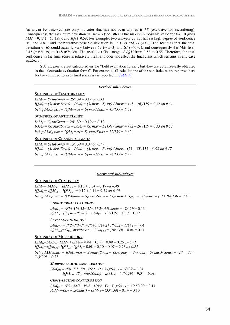
IDRAIM – STREAM HYDROMORPHOLOGICAL EVALUATION, ANALYSIS AND MONITORING SYSTEM
34
As it can be observed, the only indicator that has not been applied is F8 (exclusive for meandering). Consequently, the maximum deviation is 142 – 3 (the latter is the maximum possible value for F8). It gives IAM = 0.47 (= 65/139), and IQM=0.53. For example, two answers do not have a high degree of confidence (F2 and A10), and their relative possible deviation is +2 (F2) and -3 (A10). The result is that the total deviation of 65 could actually vary between 62 (=65–3) and 67 (=65+2), and consequently the IAM from 0.45 (= 62/139) to 0.48 (67/139). The result is a final range of IQM from 0.52 to 0.55. Therefore, the total confidence in the final score is relatively high, and does not affect the final class which remains in any case moderate.
Sub-indexes are not calculated on the “field evaluation forms”, but they are automatically obtained in the “electronic evaluation forms”. For example, all calculations of the sub-indexes are reported here for the compiled form (a final summary is reported in Table 6).
Vertical sub-indexes
SUB-INDEX OF FUNCTIONALITY IAMF = SF tot/Smax = 26/139 = 0.19 on 0.31 IQMF = (SF max/Smax) – IAMF = (SF max – SF tot) / Smax = (43 – 26)/139 = 0.12 on 0.31 being IAMF max = IQMF max = SF max/Smax = 43/139 = 0.31
SUB-INDEX OF ARTIFICIALITY IAMA = SA tot/Smax = 26/139 = 0.19 on 0.52 IQMA = (SA max/Smax) – IAMA = (SA max – SA tot) / Smax = (72 – 26)/139 = 0.33 on 0.52 being IAMA max = IQMA max = SA max/Smax = 72/139 = 0.52
SUB-INDEX OF CHANNEL CHANGES IAMV = SV tot/Smax = 13/139 = 0.09 on 0.17 IQMV = (SV max/Smax) – IAMV = (SV max – SV tot) / Smax= (24 – 13)/139 = 0.08 on 0.17 being IAMV max = IQMV max = SV max/Smax = 24/139 = 0.17
Horizontal sub-indexes
SUB-INDEX OF CONTINUITY IAMC = IAMCL + IAMCLA = 0.13 + 0.04 = 0.17 on 0.40 IQMC = IQMCL + IQMCLA = 0.12 + 0.11 = 0.23 on 0.40 being IAMC max = IQMC max = SC max/Smax = (SCL max + SCLA max)/ Smax = (35+20)/139 = 0.40
LONGITUDINAL CONTINUITY IAMCL = (F1+A1+A2+A3+A4/2+A5)/Smax = 18/139 = 0.13 IQMCL=(SCL max/Smax) – IAMCL = (35/139) – 0.13 = 0.12
LATERAL CONTINUITY IAMCLA = (F2+F3+F4+F5+A6/2+A7)/Smax = 5/139 = 0.04 IQMCLA=(SCLA max/Smax) – IAMCLA = (20/139) – 0.04 = 0.11
SUB-INDEX OF MORPHOLOGY IAMM=IAMCM+IAMCS+IAMS = 0.04 + 0.14 + 0.08 = 0.26 on 0.51 IQMM=IQMCM+IQMCS+IQMS = 0.08 + 0.10 + 0.07 = 0.26 on 0.51 being IAMM max = IQMM max = SM max/Smax = (SCM max + SCS max + SS max)/ Smax = (17 + 33 + 21)/139 = 0.51
MORPHOLOGICAL CONFIGURATION IAMCM = (F6+F7+F8+A6/2+A8+V1)/Smax = 6/139 = 0.04 IQMCM=(SCM max/Smax) – IAMCM = (17/139) – 0.04 = 0.08
CROSS-SECTION CONFIGURATION IAMCS = (F9+A4/2+A9/2+A10/2+V2+V3)/Smax = 19.5/139 = 0.14 IQMCS=(SCS max/Smax) – IAMCS = (33/139) – 0.14 = 0.10

IDRAIM – STREAM HYDROMORPHOLOGICAL EVALUATION, ANALYSIS AND MONITORING SYSTEM
35
SUBSTRATE IAMS = (F10+F11+A9/2+A10/2+A11)/Smax = 11.5/139 = 0.08 IQMS=(SS max/Smax) – IAMS = (21/139) – 0.08 = 0.07
SUB-INDEX OF VEGETATION IAMVE = (F12+F13+A12)/Smax = 5/139 = 0.04 on 0.09 IQMVE=(SVE max/Smax) – IAMVE = (13/139) – 0.04 = 0.06 on 0.09 being IAMVE max = IQMVE max = SVE max/Smax = 13/139 = 0.09
Table 6 – Summary of sub-indexes for the example in the compiled form. In the last column on the right the maximum possible value for the sub-index of each category is reported.
SUB-INDEXES IAM IQM TOTAL Vertical
FUNCTIONALITY 0.19 0.12 0.31 ARTIFICIALITY 0.19 0.33 0.52 CHANNEL CHANGES 0.09 0.08 0.17
Horizontal CONTINUITY 0.17 0.23 0.40 Longitudinal 0.13 0.12 Lateral 0.04 0.11 MORPHOLOGY 0.26 0.25 0.51 Morphological pattern 0.04 0.08 Cross-section configuration 0.14 0.10 Substrate 0.08 0.07 VEGETATION 0.04 0.06 0.09

IDRAIM – STREAM HYDROMORPHOLOGICAL EVALUATION, ANALYSIS AND MONITORING SYSTEM
ii
APPENDIX 2
EVALUATION FORM FOR CONFINED CHANNELS

IDRAIM – STREAM HYDROMORPHOLOGICAL EVALUATION, ANALYSIS AND MONITORING SYSTEM
1

IDRAIM – STREAM HYDROMORPHOLOGICAL EVALUATION, ANALYSIS AND MONITORING SYSTEM
2

IDRAIM – STREAM HYDROMORPHOLOGICAL EVALUATION, ANALYSIS AND MONITORING SYSTEM
3

IDRAIM – STREAM HYDROMORPHOLOGICAL EVALUATION, ANALYSIS AND MONITORING SYSTEM
4

IDRAIM – STREAM HYDROMORPHOLOGICAL EVALUATION, ANALYSIS AND MONITORING SYSTEM
iii
APPENDIX 3
EVALUATION FORM FOR SEMICONFINED OR
UNCONFINED CHANNEL

IDRAIM – STREAM HYDROMORPHOLOGICAL EVALUATION, ANALYSIS AND MONITORING SYSTEM
1

IDRAIM – STREAM HYDROMORPHOLOGICAL EVALUATION, ANALYSIS AND MONITORING SYSTEM
2

IDRAIM – STREAM HYDROMORPHOLOGICAL EVALUATION, ANALYSIS AND MONITORING SYSTEM
3

IDRAIM – STREAM HYDROMORPHOLOGICAL EVALUATION, ANALYSIS AND MONITORING SYSTEM
4

IDRAIM – STREAM HYDROMORPHOLOGICAL EVALUATION, ANALYSIS AND MONITORING SYSTEM
5