
Guide to the (Evolving) Enterprise Architecture Body of ...
141
EABOK DRAFT Public release approved; distribution unlimited Case No. 04-0104, 04-0105 Guide to the (Evolving) Enterprise Architecture Body of Knowledge Draft 6 February 2004 EABOK A Project of The MITRE Corporation Editor MITRE McLean, Virginia Dr. Paula J. Hagan, W900, The MITRE Corporation © 2004 The MITRE Corporation Not an official position of The MITRE Corporation Draft Working Materials – There may be errors and inconsistencies in the materials herein 2004 The MITRE Corporation. All rights reserved. This is the copyright work of the MITRE Corporation. For further information, please contact The MITRE Corporation, Contracts Office, 7515 Colshire Drive, McLean, VA 22102 (703) 883-6000. MITRE Corporation 1
Transcript of Guide to the (Evolving) Enterprise Architecture Body of ...
EABOK DRAFT Public release approved; distribution unlimited Case No. 04-0104, 04-0105
Guide to the (Evolving) Enterprise Architecture Body of Knowledge
Draft
6 February 2004
EABOK
A Project of The MITRE Corporation
Editor
MITRE McLean, Virginia
Dr. Paula J. Hagan, W900, The MITRE Corporation
© 2004 The MITRE Corporation
Not an official position of The MITRE Corporation
Draft Working Materials – There may be errors and inconsistencies in the materials herein
2004 The MITRE Corporation. All rights reserved. This is the copyright work of the MITRE Corporation. For further information, please contact The MITRE Corporation, Contracts Office, 7515 Colshire Drive, McLean, VA 22102 (703)
883-6000.
MITRE Corporation 1

EABOK DRAFT Public release approved; distribution unlimited Case No. 04-0104, 04-0105
Table of Contents
Participants.......................................................................................................................... 5 1. Introduction to the Guide ................................................................................................ 6 2. EA Charter and Context................................................................................................ 12
2.1 Evolution of the Definition of Enterprise Architecture .......................................... 12 2.2 EA Legislation and Guidance ................................................................................. 17
2.2.1 The Evolution of EA-Related Legislation ....................................................... 17 2.2.2 United States Code Sections Relevant to EA .................................................. 19
) Reference Model (NCOW RM)
3.4
2.2.3 Refining EA Guidance through OMB Circulars.............................................. 19 2.2.4 EA Guidance from the CIO Council................................................................ 20
2.5 Historical Developments in EA .............................................................................. 22 3. Foundational Practices and Tools for EA Development............................................... 26
3.1 Enterprise Architecture Frameworks ...................................................................... 28 3.1.1 What is an Enterprise Architecture Framework?............................................. 28 3.1.2 The Zachman EA Framework – Foundational Ideas ....................................... 29 3.1.3 Overview of Major Federally-Sponsored Frameworks ................................... 31 3.1.4 State and Industry-Sponsored Frameworks ..................................................... 40 3.1.5 Comparing Frameworks................................................................................... 41
3.2 Reference Models and Reference Architectures..................................................... 44 3.2.1 OMB Reference Models: The Federal Enterprise Architecture (FEA) ........... 44 3.2.2 Net-Centric Operations and Warfare (NCOW- Future...................................................................................................................... 57 3.2.3 The Global Information Grid (GIG) – Future.................................................. 57
3.3 Processes for Developing the EA ........................................................................... 58 3.3.1 Introduction...................................................................................................... 58 3.3.2 DODAF Six Step Process ................................................................................ 58 3.3.3 MetaGroup Process Model .............................................................................. 59 3.3.4 Spewak’s Enterprise Architecture Planning .................................................... 60 3.3.5 Practical Guide Process.................................................................................... 62 3.3.6 TOGAF Architecture Development Method (ADM) ...................................... 63 3.3.7 Levis Process for Developing Products for the C4ISR (DODAF) Framework63 3.3.8 Other EA Development Processes ................................................................... 64
Modeling Methods ............................................................................................ 66 3.4.1 Introduction...................................................................................................... 66 3.4.2 The Business Process Model ........................................................................... 67 3.4.3 The Data Model – Future ................................................................................. 82 3.4.4 Other Modeling Methods – Future .................................................................. 82
3.5 Architecture Modeling Tools.................................................................................. 83 3.5.1 Types of Architecture Tools and Users ........................................................... 84 3.5.2 Tool Assessment Criteria ................................................................................. 86 3.5.3 Assessment Approach ...................................................................................... 89 3.5.4 Issues with Choosing a Tool ............................................................................ 90 3.5.5 Issues with Organizational Use of Automated Tools ...................................... 91 3.5.6 Recommended Solution ................................................................................... 91
Dummy heading to clear text ............................................................................................ 92
MITRE Corporation 2

EABOK DRAFT Public release approved; distribution unlimited Case No. 04-0104, 04-0105 4. Establishing and Managing the EA Program................................................................ 93
4.3.1 Determining the Information Needed for the Enterprise Architecture ............ 95 4.3.2 Tailoring EA Products for Specific Circumstances .................................. 97
4.5 Risks...................................................................................................................... 104 4.9 Maturing Agency EA Efforts............................................................................... 106
4.9.1 Vision, Values, and Leadership ..................................................................... 106 4.9.2 Areas of Responsibility and Establishing Cooperation ................................. 106 4.9.3 Purpose and Scope ......................................................................................... 107 4.9.4 Simplifications for the Initial EA Products.................................................... 107 4.9.5 Initial and Maturing Processes....................................................................... 107
5. Engineering the EA..................................................................................................... 110 5.1 Engineering Issues for EA Views ......................................................................... 110
5.1.1 The Business Architecture View – FUTURE ................................................ 110 5.1.2 The Data Architecture View .......................................................................... 111 5.1.3 Infrastructure – Future ................................................................................... 115 5.1.4 Security .......................................................................................................... 115
5.3 Component-Based Architectures – Future............................................................ 116 5.4 Federated Architectures – Future.......................................................................... 116 5.5 Using Reference Models and Reference Architectures – Future.......................... 116 5.6 Issues with Legacy Systems – Future ................................................................... 116 5.8 Achieving Flexibility to Incorporate New Technology - Future .......................... 126 5.9 Sequencing Plan – Future ..................................................................................... 126
6. Using the Enterprise Architecture............................................................................... 127 6.1 Compliance within the Service or Agency – Future ............................................. 127 6.2 EA Use in Transformation - Future ...................................................................... 127
6.2.1 Financial......................................................................................................... 127 6.2.2 Business Operations – EA Use in BPR and Process Improvement – Future. 128 6.2.3 Technical – EA Use in Systems Design and Engineering – FUTURE.......... 129 6.2.4 Organizational – EA Use in Organizational Change Management ............... 129
7. Evaluating EA............................................................................................................. 130 7.1 EA Maturity Models ............................................................................................. 130 7.2 Seven High-Level EA Evaluation Criteria ........................................................... 132 7.3 Assessment of EA Products - Future .................................................................... 134 7.4 Assessment of EA Development Processes - Future ............................................ 134 7.5 Assessment of EA Usage Processes – Future ....................................................... 135 7.6 Assessment of EA Resources – Future ................................................................. 135
8. Lessons Learned and Practical Experience................................................................. 136 EABOK Glossary............................................................................................................ 138
MITRE Corporation 3

EABOK DRAFT Public release approved; distribution unlimited Case No. 04-0104, 04-0105 Forward, Preface, Next Steps, Acknowledgements - FUTURE
Acknowledgement Thanks to Frank Driscoll for championing the idea of a Guide to the EABOK and supporting the effort.
Next Steps
Consensus
Best practices EE Revised February 6, 2004
Enhancement
MITRE Corporation 4

EABOK DRAFT Public release approved; distribution unlimited Case No. 04-0104, 04-0105
Participants
Originator – Frank Driscoll
Contributors Reviewers
Arries, Donald Anderson, John Dandashi, Fatma Cane, Sheila Dello Russo, Francis M. Garvey, Paul R. Hagan, Paula J.
Reedy, Ann Woodward, Beverly S. Yokley, Charles A.
Driscoll Jr., Francis B. Klingler, Carol Sowell, P. Kathie Taylor, Sally Yokley, Charles A.
Mularz, Diane
Dandashi, Fatma
MITRE Corporation 5

EABOK DRAFT
Chapter 1
1. Introduction to the Guide1
Enterprise Architecture (EA) is a rapidly evolving but still immature discipline; however, there is considerable knowledge about the discipline available. Capturing and organizing that knowledge will help practitioners advance the discipline by both defining and bounding EA concepts and practices and help others by explaining and showing
guide for technical developers.
Purpose of the Guide
The Guide to the EABOK is a guide, not the EA body of knowledge itself.
Scope
relationships among the elements of the discipline.
An EA describes how the elements of an organization fit together – the business processes, organizations responsible for them, Information Technology (IT) capabilities and infrastructure – today and in the future. The EA also describes how the elements transition to support the organization’s strategic plans. Federal agencies are required to develop an EA to facilitate capital planning and IT development sequencing. In addition, the EA defines high level interoperability needs and specifies standards. It is a useful
The purpose of the Guide to the EA Body of Knowledge (EABOK) is to provide a characterization of and structure to the knowledge content of the EA discipline, promote a consistent view of EA, begin to bound the scope of the discipline, and place the EA discipline in the context of related disciplines. The guide provides topical access to the EABOK. It subdivides EA into knowledge areas and topics within each knowledge area, presents overviews of each topic, and gives references to sources of further information.
The reader may observe that some overviews are summaries of several specific methods or techniques. At the current level of maturity EA evolution, no definitive ‘winner’ of that particular area has yet emerged, but there are dominant contributors. Other overviews are more in-depth tutorials because suitable reference materials for the topic have not been developed. As the field matures and EA becomes more of an engineering discipline, a more even presentation of topic overviews will be provided.
The Guide to the EABOK addresses the purpose, creation, engineering, use, evaluation, and management of an EA and associated best practices, governance, legislation, and guidance. The guide also relates the EA to other disciplines. It does not address the implementation of the EA through the closely related discipline of Enterprise Engineering (EE) in this first edition.
1 Revised January 28, 2004
MITRE Corporation 6
EABOK DRAFT
Intended Audience
The guide is initially intended to serve MITRE in focusing corporate perspectives on EA to present consistent and cohesive guidance to our sponsors on the use and benefits of the discipline of EA. At a later date, the guide is intended to serve Government EA practitioners by providing an organized view of the EA discipline, identifying best practices, and pointing the reader to references with further information. The guide is also intended to serve the engineer and manager from other disciplines by providing an understanding of terms, overview of EA practices, and explanation of how EA fits with
organizing EA presentations.
EA Charter and Context
Evaluating EA
Lessons learned and practical advice
only at this writing.
other disciplines. The guide is useful for teachers in defining course content and
Organization of the Guide
There are many ways to decompose EA into a set of coherent knowledge areas, particularly for a new domain where all knowledge areas may not be recognized at this writing. This guide uses the following knowledge areas:
Foundational practices and tools for EA development
Establishing and managing the EA program
Engineering the EA
Using the EA
Each of the knowledge areas is broken down into a set of topics. The topic breakdown does not assume a particular viewpoint, architecture approach, or philosophy. A write-up is presented for many of the topics in this first edition. References point the reader to further information on the topic at the end of the write-up. Some topics have references
The Knowledge Areas
Figure 1 shows the knowledge areas and topics associated with them. The following paragraphs discuss the topics within the knowledge areas.
MITRE Corporation 7

EABOK DRAFT
l
ll
ii i i
EA i l
i i
latiGui
ic i
i l l
ity ls
i
l
i
i
Financiali
i
l
Design and i
i l –
i l Change
l
i
li
li
lii ls
i
il i
i i
in i
EA Li le
i
ing
ity
i l
i
ii
i
Usi
i
iies
ing Plan iti ing
l
EA Charter and Context
EA Knowledge Areas
EA Charter and
Context
FoundationaPractices and Too s for EA
Deve opment
Establish ng and Managing
the EA Program
Eng neer ng the EA
Evaluat ng Using the EA
Lessons Learned and
Pract caAdvice
Def nit on of EA
Legis on and dance
EA and StrategPlann ng
Scope and Boundary Of EA
Histor caDeve opments In EA
EA MaturMode
Assessment of EA Quality and Propert es
Assessment of EA Products
Assessment of EA Deve opment Processes
Assessment of EA Usage Processes
Assessment of EA Resources
1/6/04
Compliance w thin the Agency
Transform ng the Agency
– EA Use w th Business Cases, CPIC, and Performance Assessment
Business Operat ons – EA Use in BPR and Process Improvement
Technica – EA Use in Systems
Eng neering
Organizat onaEA Use in Organizat ona
Management
EA Frameworks
Reference Models
EA Deve opment Processes
Model ng Methods Business Process Mode ng
Data Modeling Other Mode ng
Methods
EA Mode ng and Analys s Too
EA Governance
EA Plann ng
EA Ta or ng
EA Costs
Risks
EA Conf gurat on Management
IssuesStaff ng the EA Program
fecyc
Matur ng the EA Program
EngineerIssues for Views
Business Architecture
Data Architecture
Infrastructure Secur
Arch tecturaPatterns
Component-Based Arch tectures
Serv ce-oriented Arch tectures
Federated Arch tectures
ng Reference Models and Reference Arch tectures
Issues with Legacy Systems
COTS Issues
Flexibil ty and Other Propert
SequencTrans onand evo ution
Figure 1. EA Knowledge Areas and their Associated Topics
EA has been rapidly evolving since the early 1990s; the definition, scope, and guidance for EA have likewise evolved. This knowledge area covers the evolution of the definition of EA in Federal writings, legislation and guidance mandating agencies develop and use EAs, and how EA is intertwined with strategic planning. The knowledge area also covers the scope and bounds of EA with respect to other disciplines and some historical information on major developments leading to the current state of EA practice.
Foundational Practices and Tools for EA Development
An enterprise architect’ repertoire includes a set of basic tools and practices that could apply at any agency or Service. Normally an agency does not use all of the practices and tools, but rather uses one of several options. The Foundational Practices and Tools knowledge area has five topics: EA frameworks, reference models and reference architectures, EA development processes, modeling methods, and EA modeling and analysis tools. An EA framework provides an organizational structure for the information to be covered in an EA. The topic write-up provides an overview of several widely known EA Frameworks. EA reference models and reference architectures provide a
MITRE Corporation 8

EABOK DRAFT
standard or common categorization of the critical elements of the concept, process, or object being modeled and may serve as a point of departure for more detailed specification. They enable the comparison among various elements. The write-up provides an overview of the OMB Reference Models. Others will be added in a later edition. The topic write-up for EA development processes examines several sources of process information including the DOD Architecture Framework (DODAF), Steven Spewak’s Enterprise Architecture Planning, the CIO Council’s A Practical Guide to tie Federal Enterprise Architecture, and The Open Group’s Architecture Development Method (ADM).
efforts and what to do later.
An EA normally includes models of the business processes, data, and infrastructure and a variety of modeling methods can be used to create them. Along with selecting modeling methods, the agency must select modeling and analysis tools. As commercial software packages, modeling software is being enhanced rapidly to support EA efforts. The topic presentation discusses issues in selecting EA tools and provides a list of selection criteria with references to recent comparison studies.
Establishing and Managing the EA Program
An EA Program, like other programs, needs policy, an organization structure, staff positions, approval boards, procedures, planning, funding, and other management attention. This knowledge area has nine topics directed at these and other subjects to make the EA Program a success. EA Governance addresses the policies, roles and responsibilities, processes, approval mechanisms, and other governance needed to establish and operate an EA Program. The topics also include planning; tailoring the EA project, processes, and products; costs and issues related to costs of establishing and maintaining the EA program; risks associates with the EA and possible mitigation strategies; and EA staffing issues. The EA and the enterprise capabilities its implementation changes must be placed under Configuration Management and EA lifecycle processes must be in place to keep the EA current and relevant. These two topics will be addressed in a future version of the guide. As an agency begins to establish an EA program, to conserve resources they want to separate those things that must be done first from those things that can be postponed for a time. The topic on maturing the EA Program provides advice based in government experience on how to simplify initial
Engineering the EA
Developing a quality EA is not just a matter of using a framework and following a process. There are some engineering decisions to be made and tradeoffs to be considered. Which decisions are EA decisions and which decisions are systems engineering decisions is not always clear. How to incorporate security into the EA is increasingly important. The Engineering the EA knowledge area has ten topics that begin to address engineering issues in the EA. They include engineering issues in different views, including the business, data architecture, infrastructure, and security; architectural patterns; component-based architectures; service-oriented architectures; federated architectures;
MITRE Corporation 9
EABOK DRAFT
using reference models and reference architectures; issues with legacy systems; COTS issues; flexibility and other properties need to incorporating new technology; and the sequencing plan, sometimes called the transition plan (Futures).
Using the EA
The EA is both a tool for executives, managers, and technical developers. Managers and executives use the EA to ensure investments and systems are linked to the mission and agency strategy. Executives and managers also use the EA for planning and sequencing
Evaluating EA
Lessons Learned and Practical Advice
Appendices
acquisitions and making sure investments are effective and non redundant. Engineers use the EA to examine redundancy, consistency, integration, interoperability, and standardization issues and to look for ‘good design’. The EA provides management visibility and control over investments while providing a shared vision of the future direction across the agency. This knowledge area has two topics, one with four subtopics: Compliance within the Agency or Service and Transforming the Agency EA with sub-topics addressing financial practices using the EA with business cases and Capital Planning and Investment Control (CPIC), EA use in business process transformation, EA use for technical transformation through systems design and engineering, and EA organizational use in transformation of the Agency or Service (Future).
There has been considerable EA work and many products produced, and the quality and usefulness of that work needs to be evaluated. This knowledge area has six topics: EA maturity models, EA quality and properties, assessment of EA products (Future), assessment of the EA development processes (Future), assessment of EA usage processes (Future), and assessment of EA resources, staff, and capabilities (Future).
This knowledge area condenses some of the EA experience and ‘mis-experience’ into succinct lessons learned. As this knowledge area grows, it will be subdivided into topics such as making transformation more efficient, on the selection of modeling tools, managing the team and subcontractor, or designs to avoid.
Appendix A provides a glossary of EA-related terms.
References
Guide to the Software Engineering Body of Knowledge Trial Version SWEBOK, James W. Moore, editor, IEEE Computer Society, May 2001.
MITRE Corporation 10

EABOK DRAFT
Guide to the Program Management Body of Knowledge (PMBOK), Project Management Institute, http://www.pmi.org/prod/groups/public/documents/info/pp_pmbok2000welcome.asp
Configuration Management Body of Knowledge - http://www.cmcrossroads.com/cgi-bin/cmwiki/bin/view.cgi/CM/CMBoK
MITRE Corporation 11

EABOK DRAFT
Chapter 2
2. EA Charter and Context
Table of Contents 2.1 Evolution of the Definition of Enterprise Architecture 2.2 EA Legislation and Guidance
2.2.1. The Evolution of EA-Related Legislation 2.2.2. United States Code Sections Relevant to EA
2.1 Evolution of the Definition of Enterprise Architecture2
Dr. Paula Hagan
703 883 6518
2.2.3. Refining EA Guidance through OMB Circulars 2.2.3.1 Required EA Content - OMB A-130 2.2.3.2 Relating Business Cases to EA in Budget Submissions - OMB Circular A-11 2.2.3.3 OMB A-76 Performance of Commercial Activities
2.2.4. EA Guidance from the CIO Council 2.2.4.1 An EA Framework - The Federal Enterprise Architecture Framework 2.2.4.2 EA Development Process and Governance – A Practical Guide to Federal Enterprise Architecture 2.2.4.3 EA and CPIC - Architecture Alignment and Assessment Guide
2.3 Enterprise Architecture is a Strategic Management Tool 2.3.1 EA Solidifies Strategic Plan and Ensures Mission Alignment 2.3.2 EA Guides Capital Investment 2.3.3 EA Basis for Performance Measures and Assessment 2.3.4 EA Guides Technical Development
2.4 Scope and Boundaries of EA 2.5 Historical Developments in EA
MITRE Corporation, Software Engineering Center
The definition of Enterprise Architecture (EA) has evolved over several years. The E-Government Act of 2002 (Public Law (PL) 107-347) states that Enterprise Architecture
“(A) means - (i) a strategic information asset base, which defines the mission; (ii) the information necessary to perform the mission; (iii) the technologies necessary to perform the mission; and (iv) the transitional processes for implementing new technologies in response to changing needs; and
(B) includes -(i) a baseline architecture; (ii) a target architecture; and (iii) a sequencing plan”.
2 Revised January 19, 2004
MITRE Corporation 12
EABOK DRAFT
This definition draws on terms used elsewhere in Federal EA writings. The following paragraphs trace the evolution of the definition of EA and show the source and meaning given to the terms in those sources.
Webster’s Dictionary associates the word architecture with the concepts of ‘the science, art, or profession of designing and constructing…., a style of construction, … any framework, system, etc., and the design and interaction of components …‘.
In April 1995, Garlan and Perry cited a definition of software architecture developed in
architecture work.
3
The 1999 (FEAF) describes the FEAF itself,
4
strategic information asset base
Management of Federal
group discussion at the Software Engineering Institute (SEI) as
The structure of the components of a program/system, their interrelationships, and principles and guidelines governing their design and evolution over time.
IEEE built on this definition in its IEEE Recommended Practice for Architectural Description of Software-Intensive Systems (STD 1471-2000). The emphasis on components, relationships, principles, and guidelines has continued to characterize
The 1996 Clinger Cohen Act (CCA) (PL 104-106) requires agencies to have an Information Technology Architecture which, “with respect to an executive agency, means an integrated framework for evolving or maintaining information technology and acquiring new information technology to achieve the agency’s strategic goals and information resources management goals” (CCA Section 5125). The CCA Information Technology Architecture concept was expanded to an EA which includes the description of the business processes in OMB A-130 guidance.
Federal Enterprise Architecture Frameworkan architecture framework, as an organizing mechanism for managing the development and maintenance of architecture descriptions. It provides a structure for organizing Federal resources and describing and managing the Federal Enterprise Architectureactivities. The FEAF introduces the term ; it describes the Federal Enterprise Architecture as a ‘strategic information asset base that defines the business, information necessary to operate the business, technologies necessary to support the business operations, and transitional processes for implementing new technologies in response to the changing needs of the business’ (FEAF p 2).
The November 2000 version of OMB Circular A-130: Information Resources describes an Enterprise Architecture as the explicit description and documentation of the current and desired relationships among business and
3 The choice of the word ‘framework’ reflected one aspect of the dictionary definition of architecture, but overlayed the term within the EA field, confusing it with the concept of an architecture framework such as that already published by Zachman as an organizing structure for architecture information rather than the architecture itself. 4 The FEAF reference to a Federal Enterprise Architecture should not be confused with the OMB Reference Model reference to a Federal Enterprise Architecture. See the description of the FEAF under Frameworks and the OMB Reference Model sections for a fuller explanation.
MITRE Corporation 13
EABOK DRAFT
management processes and information technology. It describes the current and target architectures, and includes the rules, standards, and systems lifecycle information to optimize and maintain the environment which the agency wishes to create and maintain by managing its Information Technology (IT) portfolio. The EA must also provide a strategy that will enable the agency to support its current state and also act as the roadmap for transition to its target environment. The transition processes will include agency capital planning and investment control processes, agency EA planning processes, and agency systems lifecycle methodologies. The EA will define principles and goals and set direction on such issues as the promotion of interoperability, open systems, public
The 2001
The Practical Guide describes a baseline architecture
is
architecture productsSequencing Plan
5 An
access, compliance with the Government Paperwork Elimination Act (GPEA) (PL 105277), end user satisfaction, and IT security. In the creation of an EA, agencies must identify and document business processes, information flow and relationships, applications, data descriptions and relationships, and technology infrastructure and include a technical reference model and standards profile.
A Practical Guide to the Federal Enterprise Architecture (Practical Guide) built on the definitions in the FEAF and OMB A-130 to define an EA as “a strategic information asset base, which defines the mission, the information necessary to perform the mission and the technologies necessary to perform the mission, and the transitional processes for implementing new technologies in response to the changing mission needs. An enterprise architecture includes a baseline architecture, target architecture, and a sequencing plan (p 5)”. At the same time, the Practical Guide defines an architecture as “the structure of components, their interrelationships, and the principles and guidelines governing their design and evolution over time (p 5)”.
as the set of products that portray the existing enterprise, the current business practices, and the technical infrastructure. It is commonly referred to as the ‘As-Is’ or current architecture. The target architecturethe set of products that portray the future or end-state enterprise, generally captured in the organization’s strategic thinking and plans. It is commonly referred to as the ‘To-Be’ architecture. The are the graphics, models, and/or narrative that depict the enterprise environment and design. The is a document that defines the strategy for changing the enterprise from the current baseline to the target architecture. It schedules multiple, concurrent, interdependent activities, and incremental builds that will evolve the enterprise.
The EA is distinct from an EA framework, though the two are sometimes confused. A framework is a logical structure for classifying and organizing complex information.enterprise architecture framework provides an organizing structure for the information contained in and describing an EA. The framework does not contain the EA itself. Many organizations can use the same EA framework, but each EA with its content is organization-specific.
Today, there is general agreement that, at a minimum, the EA includes models of business practices or processes, data, computing systems for mission-related and business
5 From the Practical Guide to the Federal Enterprise Architecture
MITRE Corporation 14

EABOK DRAFT
support, networks and other technology infrastructure, for both the baseline, or current, and target architectures; several source also include the organization structure. The EA includes a standards profile, security considerations, and a sequencing plan, sometimes called a transition plan; is linked to agency strategic plans; and is a major basis for investment decisions. Figure 1 shows the elements on an EA.
i i
• j
• •
Standards – TRM Standards – TRM
Secu
rity
Info
rmat
ion
Flow
Structure-Relat onships
Applications Technology Organization
Business Data
Secu
rity
Info
rmat
ion
Flow
Structure- Relat onships
Applications Technology Organization
Business Data
Baseline Architecture
Target Architecture
Mission
Sequencing Plan
Transition Processes Capital Planning and Investment Control (CPIC) EA Planning System lifecycle methodologies
Figure 1. Elements of an Enterprise Architecture
The agency achieves its target architecture by: Managing its investment portfolio to invest in pro ects that implement the agency strategy in accordance with the sequencing plan, Enforcing the EA through its Configuration Management (CM) boards, Managing the delivery of capabilities identified in the EA through its Systems/Software Development Life Cycle (SDLC) and Capital Planning and Investment Control (CPIC) processes, and
• Evaluating the result of its delivered capabilities through its CPIC processes. The agency continually updates its EA through its EA planning processes.
MITRE Corporation 15

EABOK DRAFT
Editorial Comment
Architects and planners should keep in mind the descriptive communication, planning, engineering, and management value of the EA when defining it for their intentions.
One might try to make a distinction between an EA as a description and an EA as an information asset base. A description calls for something to be pictured with words. As an architecture, an EA is usually pictured with models and words describing the models. These models are best captured electronically with searchable, analyzable data available
2000.
Officers Council, September 1999.
Officers Council, February 2001.
.
from them, but the word descriptions should not be lost. As an information asset base, one might be tempted to think of the EA as only a (relational) database and omit the descriptive and graphical aspects of the architecture. To serve EA users well, the EA must be viewed as a strategic information asset base with models, text descriptions, and relationships available in both electronic and human readable form.
References
Clinger Cohen Act of 1996 (PL 104-106) - Legislation can be found by law number on http://thomas.loc.gov/
E-Government Act of 2002 (PL 107-347) - Legislation can be found by law number on http://thomas.loc.gov/
OMB Circular A-130: Management of Federal Information Resources, November 30, http://www.whitehouse.gov/omb/circulars/a130/a130trans4.html
Federal Enterprise Architecture Framework (FEAF) Version 1.1, Chief Information http://www.cio.gov/documents/fedarch1.pdf
A Practical Guide to Federal Enterprise Architecture, Version 1.0, Chief Information http://www.cio.gov/documents/bpeaguide.pdf
IEEE Recommended Practice for Architectural Description of Software-Intensive Systems, IEEE Standard 1471-2000. http://ieeexplore.ieee.org
Webster’s New World Dictionary of American English, Third College Edition, Victoria Neufeldt editor, New York: Simon and Schuster, Inc., 1988.
Garlin and Perry, Guest Editorial, IEEE Transactions on Software Engineering Vol 21 No 4 (April).
MITRE Corporation 16
EABOK DRAFT
2.2 EA Legislation and Guidance6
Dr. Paula Hagan MITRE Corporation, Software Engineering Center
703 883 6518 [email protected]
(GPRA
(PRA) of 1995
The Federal government has been passing legislation and providing guidance to agencies and Services to improve management and financial accountability for over a decade. Using an Enterprise Architecture (EA) to identify needs, plan investments, establish transition strategies, and guide development is a mechanism to improve management and financial accountability. The following sections outline how direction on EA has evolved through legislation, Office of Management and Budget (OMB) direction, and Chief Information Officers (CIO) Council guidance. The material covers only items at the Federal level, not DoD, Service, or Agency-specific direction.
2.2.1 The Evolution of EA-Related Legislation
Developing and using an EA is directed at improving the management, planning, investment, and technology capabilities of an enterprise. To improve the management and planning of government agencies, the Government Performance and Results Act
) of 1993 requires each agency to develop and submit to OMB a five year strategic plan stating the mission, goals, and objectives for its major functions and operations and a description of how they will be achieved. The detailed requirements for the strategic plan are addressed in OMB Circular A-11. The strategic plan is essential to developing a target enterprise architecture; it provides the vision and goals for major agency functions and operations which the target architecture must support. The GPRA required performance plan identifies performance indicators to measure outputs, service levels, and outcomes which the architecture must support.
The planning emphasis continued in the Paperwork Reduction Act (Public Law (PL) 104-13, May 22, 1995, 44 United States Code (USC) 3501 et seq.). It requires an Information Resources Management (IRM) strategic plan that describes how IRM activities help accomplish the agency mission and links to the strategic plan required by GPRA. The PRA also began the emphasis on integrated decision making by requiring integration of Information Technology (IT) management operations and decisions with organizational planning, budget, financial management, Human Resources (HR), and program decisions. It introduced the Select, Control, Evaluate terminology that eventually matured into the Capital Planning and Investment Control Process (CPIC) later described in OMB Circular A-130. The PRA also called for reducing the burden on the public.
6 Revised January 25, 2004
MITRE Corporation 17
EABOK DRAFT
the Clinger-Cohen Act (CCA) of 1996 (PL 104-106) (part of which is called the Information Technology Management Reform Act (ITMRA)), mandates an Information Technology Architecture integrated framework7 for evolving or maintaining existing information technology and acquiring new information technology to achieve the agency’s strategic and information resources management goals. The Chief Information Officer (CIO) is responsible for its development, maintenance, and facilitation. The CCA also calls for a capital planning process, process benchmarking, process revision (i.e., Business Process Reengineering (BPR)) before investing in Information Technology (IT),
GPEA)
The E-Government Act of 2002
modular contracting, and adequate security practices.
At the same time the Federal government was improving its management processes and investment practices, it was also defining characteristics of the interactions it wanted available for citizens and the operation of its technology systems. The 1998 Government Paperwork Elimination Act ( (PL 105-277, October 21, 1998) (Title 17, section 1701 FF (1710)) requires Federal agencies to provide individuals or entities that deal with the agencies the option to submit information or transact with the agency electronically, and to maintain records electronically, when practicable. The Act encourages Federal government use of a range of electronic signature alternatives.
(PL 107-347, Dec 17, 2002) continues the emphasis on electronic interaction with the government. It calls for maintaining and promoting an integrated Internet-based system for providing the Public access to government information and services, provides funding for digital signature certification, and addresses information security, privacy, and disclosure issues. It requires each agency to have a publicly accessible web site with prescribed content. It also establishes the OMB Office of Electronic Government to oversee the implementation of electronic government, oversee the development of enterprise architectures within and across agencies (Section 3602 (14)), and lead the activities of the CIO Council. It establishes the Interagency Committee on Government Information to submit recommendations for standards to enable the organization and categorization of government information in ways to be electronically searchable and interoperable across agencies. It requires a continuity of operations plan (COOP) and an inventory of major information systems and their system and network interfaces. The E-Government Act of 2002 also contains a definition of EA as a strategic information asset base with a baseline architecture, target architecture, and sequencing plan. This definition is similar to the definition in the Practical Guide to the Federal Enterprise Architecture.
Other legislation that requires capabilities in Federal agencies includes: • Freedom of Information Act (FOIA) (5 United States Code (USC) 552) calls for
public access to agency records to the greatest extent possible unless protected or exempted.
7 See the comments on the definition of EA for a clarification of the term framework in the context of EA.
MITRE Corporation 18
EABOK DRAFT
• Computer Security Act of 1987 (40 USC 1441) (PL 100-235) requires Federal agencies to identify and afford security protections commensurate with risk and harm.
• Government Information Security Reform Act (GISRA) (PL 106-398) requires efforts to secure electronic information and systems, including the integrity, confidentiality, authenticity, availability, and non repudiation of information and information systems and to assess their security management practices.
• FISMA) - Future
• Cyber Security Act of 2002 - Future
2.2.3.1 Required EA Content - OMB A-130
Federal Information Security Management Act of 2002 (
2.2.2 United States Code Sections Relevant to EA
After legislation is passed, it is added to sections of the United States Code. Some of the sections relevant to EA include Title 40 Chapter 25 on Information Technology Management which describes policies, responsibilities, and other aspects of IT management. It codifies many elements for the PRA and CCA.
CIO responsibilities are described in Title 44 Sec. 3506 and Title 40 Sec 1425. Title 40 Sec 1425 (b) (2) codifies the CIO responsibility for developing, maintaining, and facilitating a sound and integrated enterprise architecture.
2.2.3 Refining EA Guidance through OMB Circulars
The CCA and other legislation and guidance were expanded upon in Office of Management and Budget (OMB) Circular A-130: Management of Federal Information Resources (November 2000). A-130 describes the required content of an Enterprise Architecture which must be submitted to OMB. The EA is the explicit description and documentation of the current and desired relationships among business and management processes and information technology. In the EA, agencies must identify and document business processes, information flow and relationships, applications, data descriptions and relationships, and technology infrastructure, among other things. The EA must provide a strategy that will enable the agency to support its current state and transition to its target state.
OMB A-130 also describes the select, control, and evaluate components of a Capital Planning and Investment Control (CPIC) process, how agencies will ensure security in information systems, and how agencies will acquire information systems. See Chapter 6 for more information on CPIC. NOTE – OMB A-130 is being revised at this writing.
MITRE Corporation 19

EABOK DRAFT
2.2.3.2 Relating Business Cases to EA in Budget Submissions - OMB Circular A-11
OMB Circular A-11: Preparation, Submission and Execution of the Budget (Revised 05/27/2003) requires agency Capital Asset Plans (Exhibit 300 business cases) to be mapped against the OMB reference models (See Chapter 3 for a description of the OMB Reference Models.). In 2002, the Exhibit 300 had to be related to only the Business Reference Model (BRM). Mappings to other models are now required since more reference models have been published. The reader should check the latest A-11 guidance for details.
Architecture Framework (FEAF
Architecture.”
Enterprise Architecture
2.2.3.3 OMB A-76 Performance of Commercial Activities
OMB A-76: Performance of Commercial Activities should be addressed in the scope and content of governance and performance sections of an EA to reflect the basic differences between internally operated systems and outsourced managed services.
2.2.4 EA Guidance from the CIO Council
2.2.4.1 An EA Framework - The Federal Enterprise Architecture Framework
In September 1999, the Federal CIO Council published the Federal Enterprise ) Version 1.1 to “promote shared development for
common Federal processes, interoperability, and sharing of information among the agencies of the Federal Government and other Governmental agencies.” It “consists of various approaches, models, and definitions for communicating the overall organization and relationship of architecture components required for maintaining a Federal Enterprise
2.2.4.2 EA Development Process and Governance – A Practical Guide to Federal
The Federal CIO Council sponsored the publication of A Practical Guide to Federal Enterprise Architecture in February 2001 to provide ‘a step-by-step guide to assist agencies in defining, maintaining, and implementing EAs by providing a disciplined and rigorous approach to EA lifecycle management. It describes major EA program management areas, beginning with suggested organizational structure and management controls, a process for development of baseline and target architectures, and development of a sequencing plan. The guide also describes EA maintenance and implementation, as well as oversight and control.8’ More detail on the Practical Guide processes are presented in the section on EA development processes in Chapter 3.
2.2.4.3 EA and CPIC - Architecture Alignment and Assessment Guide
8 From the Preface to A Practical Guide to Federal Enterprise Architecture
MITRE Corporation 20

EABOK DRAFT
The Architecture Assessment and Alignment Guide (AAAG) was published by the CIO Council in October 2000 to provide agencies an overview of the integration of enterprise architecture with the CPIC process. The CPIC process ensures an agency follows its EA once it is approved. The AAAG identifies touchpoints between the EA and CPIC and describes a U.S. Customs Service prototype to demonstrate and document the need for an integrated architecture and investment process. The AAAG also provides an example 2 X 2 matrix that relates organizational goals with project requirements.
References
Legislation can be found by law number on
The United States Code (USC) can be searched at http://uscode.house.gov/usc.htm or located through
May 27, 2003)
2000
Officers Council, September 1999.
October 2000.
Officers Council, February 2001.
http://thomas.loc.gov/
http://www.access.gpo.gov/congress/cong013.html. It is also available at the Government Printing Office.
OMB Circular A-11: Preparation, Submission and Execution of the Budget (Revised http://www.whitehouse.gov/omb/circulars/a11/02toc.html
OMB Circular A-76: Performance of Commercial Activities, May 29, 2003 http://www.whitehouse.gov/omb/circulars/a076/a76_rev2003.pdf
OMB Circular A-130: Management of Federal Information Resources, November 30, http://www.whitehouse.gov/omb/circulars/a130/a130trans4.html
Federal Enterprise Architecture Framework (FEAF) Version 1.1, Chief Information http://www.cio.gov/documents/fedarch1.pdf
Architecture Alignment and Assessment Guide, Chief Information Officers Council, http://www.cio.gov/documents/arch_align_assess_oct_2000.pdf
A Practical Guide to the Federal Enterprise Architecture, Version 1.0, Chief Information http://www.cio.gov/documents/bpeaguide.pdf
2.3 The Enterprise Architecture Is a Strategic Management Tool
MITRE Internal Draft
2.4 Boundaries of EA and Relationship to Other Disciplines
MITRE Internal Draft
MITRE Corporation 21

EABOK DRAFT
2.5 Historical Developments in EA9
Dr. Paula Hagan MITRE Corporation, Software Engineering Center
703 883 6518 [email protected]
Enterprise Architecture (EA) contributions have come from many sources through
200519951990 2000
Clinger-Cohen
i
Levis
Fi
AAAG
commercial, Federal, state, and local government efforts. The contributions provided guidance that motivated the need for EA, structures to organize EA information, and processes to develop an EA. They shaped the description and improved the utility of the EA. Today, EA efforts are moving toward compliance issues, evaluation, and use of the EA. Figure 1 shows some major contributions to the field.
1985
Zachman Framework
Spewak EAP
Thinking Tool, Views
Contribution Strategic Plan
C4ISR AF DoD AF
Area of Development
TAFIM
Technical Reference Model
JTA
Framework Products
OMB-A130 Legislation and Guidance
Defined EA CIO, BPR
...
Hagan 9/22/2003
FEAF 1.1
TEAF
GPRA
Pract cal Guide
TRM
Converging Frameworks
CPIC
nkelstein, Chen, Yourdon, others
Frameworks
Methods and Processes
Assessment
TOGAF
Taxonomies and Standards
Early Work
OMB Ref Models
Process
E-gov Act
Performance measures, Common categories
GAO Maturity Model
Development
Figure 1. Major Developments in the History of EA
Clive Finkelstine’s development of Information Engineering in 1976 was designed to address the growing problem of data redundancy. Data modeling techniques and system analysis and design methods expanded in the 1970s and 1980s with Peter Chen’s Enterprise Relationship (E-R) diagrams, Yourdon’s structured analysis and design, and
9 Revised January 25, 2004
MITRE Corporation 22

EABOK DRAFT
others. Finkelstein states that business driven information engineering had evolved into Enterprise Engineering by 198610.
Zachman first published his EA Framework as an Information Systems Architecture Framework in 1987 and republished a revision of it as an Enterprise Architecture (EA) framework in 1992. The Zachman EA framework provides structure for EA information and serves as a thinking tool on what to consider and how to organize EA information. Steven Spewak published his Enterprise Architecture Planning text in 1995 (possibly 1993 in informal versions). The text describes a process, information to collect, and other
TOGAF) Version 1 in 1995 based on the
ADM
(first published in
DOD Architecture Framework (DODAFLevis
processes.
advice to develop an EA based on the Zachman Framework.
In the early 1990s, DOD was addressing interoperability issues that emerged in the 1991 Gulf War. The Technical Architecture Framework for Information Management (TAFIM), begun in 1992, was an effort to provide guidance for the evolution of the DoD technical infrastructure. It did not provide a specific system architecture, but rather provided the services, standards, design concepts, components, and configurations that could be used to guide the development of technical architectures that meet mission specific requirements. The TAFIM is now superceded by other documents including the Joint Technical Architecture (JTA).
The Open Group, an international vendor and technology-neutral consortium, developed The Open Group Architectural Framework (TAFIM. The TOGAF supports building business, applications, data, and technology architectures, has an architecture development Method ( ), a Technical Reference Model that provides a taxonomy of generic platform services, and a Standards Information Base (SIB) - a database of open industry standards.
The DoD developed the Command, Control, Communications, Computers, Intelligence, Surveillance, and Reconniassance (C4ISR) Architecture Framework 1996) to provide direction to contractors and agencies on how to document system architectures to allow comparability and promote interoperability across systems, projects, and Services. It has been revised several times and is now called the
). It is often adapted for EA descriptions. Alexander of George Mason University developed a process to produce architecture
descriptions according to the C4ISR framework. Several Services now have their own
DoD recognized the need for information to flow quickly and seamlessly among DoD sensors, processing and command centers, shooters, and support activities and the need for standards across the supporting systems. The DoD developed the Joint Technical Architecture (JTA) in 1997 to provide the minimum set of standards that, when implemented, facilitates the flow of information in support of the warfighter.
In the 1990s, Congress passed several pieces of legislation aimed at improving government management and performance. The Government Performance and Results
10 Finkelstein, Building Corporate Portals with XML, p 34
MITRE Corporation 23
EABOK DRAFT
Act (GPRA) required agencies to develop five year strategic plans and report on their performance annually. The Clinger Cohen Act (CCA) required the position of a Chief Information Officer (CIO) and gave the CIO responsibility for an Information Technology Architecture for the agency. The CCA also called for a capital planning process, benchmarking, and revision of a process before investing in IT.
As agencies began to create their Information Technology Architectures, the need for guidance was recognized. The CIO Council sponsored the development of the Federal Enterprise Architecture Framework (FEAF) (1999) to provide a framework based on the
OMB published OMB Circular A-130
CPIC) process
the Department of the Treasury. The Treasury EA Framework (TEAF) combined
GAO developed an EA Maturity Modeltheir EA processes in 2002.
OMB Reference Models: the Business
Zachman Framework and A Practical Guide to the Federal Enterprise Architecture (2001) to provide advice on setting up an EA program and a process for developing and maintaining the EA.
: Management of Federal Information Resources in November of 2000 amplifying CCA guidance. It defined the required content of an EA, described elements of a Capital Planning and Investment Control (required by the CCA, and discussed how agencies will ensure the security in information systems.
Several agencies developed their own EA frameworks between 1998 and 2001, notably
concepts from the Zachman-oriented FEAF and the C4ISR Architecture Framework, including many C4ISR-like products for architecture description.
to gauge the progress agencies were making with
Despite all these EA efforts, in 2002 the Government still did not have a government-wide EA on which to build its E-Gov initiatives. Therefore, OMB began to build the Federal Enterprise Architecture through five Reference Model (BRM), Performance Reference Model (PRM), Service Component Reference Model (SRM), Data Reference Model (DRM), and Technical Reference Model (TRM). These models facilitate identification of related business functions, services, and standards across the Federal government. Equally importantly, the models are aimed at developing common performance measures.
EA as a discipline is in its early years with the emphasis beginning to move from frameworks, modeling methods, and tools to compliance and performance issues. The future is likely to emphasize EA best practices, EA assessment, and effective use of the EA to improve government management.
References
Finkelstein, Clive, and Aiken, Peter, Building Corporate Portals with XML, New York: McGraw-Hill, 2000.
MITRE Corporation 24
EABOK DRAFT
Zachman, J.A., “A Framework for Information Systems Architecture”, IBM Systems Journal Vol 26, No 3, 1987.
Zachman, J.A., and Sowa, J.F., “Extending and Formalizing the Framework for Information Systems Architecture”, IBM Systems Journal, Vol 31, No 3, 1992
Spewak, Steven H., Enterprise Architecture Planning, New York: John Wiley and Sons (Copyright approximately 1993)
Architecture Design, To be published
DoD Architecture Framework Version 1.0 (Draft) http://aitc.aitcnet.org/dodfw
) Version 1.1, CIO Council,
) http://www-
http://www.opengroup.org/architecture/
Officers Council, February 2001.
Levis, A., and L. Wagenhals, C4ISR Architectures I: Developing a Process for C4ISR , Systems Engineering, Vol. 3, No. 4, Fall 2000.
Office of Management and Budget, Circular No. A-130, Management of Federal Information Resources, November 30, 2002.
Joint Technical Architecture (JTA) http://www-jta.itsi.disa.mil/
Federal Enterprise Architecture Framework (FEAFSeptember 1999.
Treasury Enterprise Architecture Framework (TEAF) Version 1, Department of the Treasury Chief Information Officer Council, July 2000.
Technical Architecture Framework for Information Management (TAFIMlibrary.itsi.disa.mil/tafim/tafim3.0/pages/word.htm http://www2.umassd.edu/swarchresearch/tafim/v4.pdf
The Open Group Architecture Framework (TOGAF):
A Practical Guide to the Federal Enterprise Architecture, Version 1.0, Chief Information http://www.cio.gov/documents/bpeaguide.pdf
The FEA Program Management Office published the OMB Reference Models. Official versions of the Reference Model descriptions can be found on the FEAPMO Web site. http://www.feapmo.gov
A Framework for Assessing and Improving Enterprise Architecture Management (Version 1.1) GAO-03-584G, United States General Accounting Office, April 2003. http://www.gao.gov/ - Contains a description of the GAO Five Stage EA Maturity Framework. NOTE – A Version 2 has been published.
MITRE Corporation 25

EABOK DRAFT
Chapter 3
3. Foundational Practices and Tools for EA Development
Developing an EA requires several key decisions in the planning process. The organization and documentation of the information to collect must be determined. The
Table of Contents
(NASCIO)
3.2.1 Overview 3.2.2 Model Overview Descriptions 3.2.2.1 Business Reference Model (BRM) 3.2.2.2
processes to use to collect, present, and market the EA must be established. The modeling methods and tools must be selected. The reference models to be related to must be determined. A team must be established. The architect draws on EA frameworks, processes, and tools that are available to all EA practitioners and tailors them to his organization’s needs. Before EA project planning or management is well under way, the architect and planners should be generally familiar with the choices available and what they can contribute. The following sections provide an overview of the major EA frameworks, reference models and reference architectures, processes to develop the EA, modeling choices, and modeling tools.
3.1 Enterprise Architecture Frameworks 3.1.1 What is an Enterprise Architecture Framework? 3.1.2 The Zachman Framework – Foundational Ideas 3.1.3 Overview of Major Federally-Sponsored Frameworks
3.1.3.1 Federal Enterprise Architecture Framework (FEAF) 3.1.3.2 DoD Architecture Framework (DODAF) 3.1.3.3 Treasury Enterprise Architecture Framework (TEAF)
3.1.4 State and Industry-Sponsored Frameworks 3.1.4.1 National Association of State Chief Information Officers
3.1.4.2 The Open Group Architecture Framework (TOGAF) 3.1.4.3 Reference Model for Open Distributed Processing (RM-ODP)
3.1.5 Comparison of Frameworks 3.2 OMB Reference Models: The Federal Enterprise Architecture (FEA)
Performance Reference Model (PRM) 3.2.2.3 Service Components Reference Model (SRM) 3.2.2.4 Technical Reference Model (TRM) 3.2.3 FEAMS
3.3 Processes for Developing the EA3.3.1 Introduction 3.3.2 DODAF Six Step Process 3.3.3 MetaGroup Process Model 3.3.4 Spewak’s Enterprise Architecture Planning 3.3.5 Practical Guide Process
MITRE Corporation 26
EABOK DRAFT
3.3.6 TOGAF Architecture Development Method 3.3.7 Levis Process for Developing Products for the C4ISR (DODAF) Framework 3.3.8 Other EA Development Processes
3.4 Modeling Methods 3.5 Tool Assessment Criteria
MITRE Corporation 27

EABOK DRAFT
3.1 Enterprise Architecture Frameworks11
Paula Hagan MITRE Corporation, Software Engineering Center
703 883 6518 [email protected]
An •
(EA), • •
3.1.1 What is an Enterprise Architecture Framework?
enterprise architecture framework Identifies the types of information needed to portray an Enterprise Architecture
Organizes the types of information into a logical structure, and Describes the relationships among the information types.
Often the information is categorized into architecture models and viewpoints.
This categorization of EA information facilitates thinking about the architecture and how the information fits together. The EA framework can also identify the product types, sometimes called models, needed to describe the EA and show how to portray linkages between different types of EA information such as mission needs, business processes, data, and IT capabilities. This helps structure and mange the development of the EA. Using predetermined EA product descriptions speeds the architecture development process. Using the same framework and product types across different but related EAs increases the comparability of the EAs and facilitates communications among the architects, planners, and developers working with the different EAs. The EA Framework is not the EA itself, but rather tells how to organize and describe the EA.
Based on the required information content of an EA (See Chapter 2 on definition of EA), an EA framework should, at a minimum, organize information types and describe the relationships between business processes, data, IT mission systems, and IT infrastructure used to perform the enterprise mission and planned to achieve the future strategy of the enterprise. The framework should also address standards, security, relating the EA to the corporate strategy and objectives, and the sequencing plan/transition strategy to move from the baseline architecture to the target architecture. Since an EA has many different users, the EA framework may also address what types of information are appropriate for different user viewpoints. Some frameworks also address repository needs or provide guidance on processes, governance, or Configuration Management. Most frameworks do not prescribe a modeling methodology, analytical methods, or tools.
The November 2000 version of OMB Circular A-130 required the use of an EA framework to develop an agency EA. With the advent of the OMB reference models, there is a trend in some circles to eliminate or minimize the importance of frameworks.
11 Revised January 31, 2004
MITRE Corporation 28

EABOK DRAFT
Two frameworks, the Federal Enterprise Architecture Framework (FEAF) and the Treasury Enterprise Architecture Framework (TEAF) are not actively supported at this time. Nevertheless, the following discussion includes these frameworks because of their contribution to the EA field. The following sections contain a brief overview of major frameworks. Table 1 provides a comparison of characteristics of several frameworks. The references point the reader to further information.
3.1.2 The Zachman EA Framework – Foundational Ideas
12
functions in the owner level.
Foundational thinking for many EA frameworks came from John Zachman’s framework for information systems architecture first published in 1987 when Zachman was working at IBM. Zachman has evolved it over time into an EA framework. His EA Framework is organized as a ‘schema’ of six columns and five rows. The columns are based on the six interrogatives what, how, where, who, when, and why leading to column titles of data, function, network, people, time, and motivation. The five rows represent the views of users of the EA - the planner, owner, designer, builder, and subcontractor. (See Figure 1.) Zachman sees each cell as independent single variables – normalized in relational database thinking; data should be treated independently of function and independent of network location to allow clarity of thinking and flexibility. Zachman uses the term primitive as opposed to composite to describe the independent single variables. A composite might combine information from several cells such as data and business function or network location. Within a cell, information might be at a high level or, as Zachman would say, at ‘an excruciating level of detail’, e.g., 10 high-level processes summarizing corporate functions at the owner level, or 200 processes detailing corporate
12 Zachman prefers the term schema instead of matrix
MITRE Corporation 29

EABOK DRAFT
13Figure 1. The Zachman EA Framework
While Zachman states that each cell has different models and constraints, no product specifications are provided, only ‘for example’ descriptions of what is in each cell. The framework also provides no direction on security (Zachman has published a note on security, but it does not contain substantive detail.) There is no discussion of standards, principles, transition strategy, or repositories. The motivation column could be construed to incorporate agency strategic vision and plans. Some columns of the framework are not as well developed as others, for example, time and motivation. The framework is methodology and tool independent.
Zachman has expanded on his original thinking and recognizes that each cell has relationships to other cells in the same row as shown in Figure 2. Data could be used in a function, transmitted between locations, or produced by a particular organization. That information could be presented in a matrix.
Today Zachman sees his framework as a thinking tool. It helps the architect and manager isolate issues and sort out what needs to be addressed. The Zachman EA Framework has contributed to the organization of several later frameworks and much architectural thinking.
13 The Zachman EA Framework diagram is available at http://www.zifa.com
MITRE Corporation 30

EABOK DRAFT
Time
ple
Net
wor
k
X
X X
X
X X
X
X
What
How
Plan
ner
Owne
r
Desig
ner
Build
er
Subc
ontra
ctor
FEAF)
Data
Function
Network
People
Motivation
After style of Stan Locke
Function
Peo
Function
15 Matrices Relate
Pairs in Row
etc.
Hagan 5/1/2002
Why
When
Who
Where
Figure 2. Zachman Identifies Relationships Across Cells in the Same Row
3.1.3 Overview of Major Federally-Sponsored Frameworks
3.1.3.1 Federal Enterprise Architecture Framework (
The 1999 Federal CIO Council-sponsored Federal Enterprise Architecture Framework (FEAF) defined eight framework components: architecture drivers, strategic direction, current architecture, target architecture, transitional processes, architectural segments, architectural models, and standards (See Figure 3). The strategic direction guides the development of the agency target architecture and includes the agency vision, principles, and goals and objectives. The architectural models define the business, data, applications, and technology architectures. The models are strongly based on the Zachman EA Framework and Zachman provided a brief (one paragraph) description of what should be in the models for the FEAF publication.
While the FEAF identifies standards and transitional processes as part of the EA, it does not identify how the standards should be organized or presented and provides no guidance on the transitional processes or transition strategy. The FEAF acknowledges the
MITRE Corporation 31
EABOK DRAFT
need for a repository, but does not provide any detail. The FEAF does not provide guidance on security.
As originally conceived, the FEAF was to be a framework for the development of the Federal Enterprise Architecture, not an agency EA. The FEAF architectural segment concept was an attempt to divide the Federal Government into cross-cutting business areas such as common administrative systems, international trade, or criminal justice. While grants and international trade pilots were developed, the concept did not move forward; it depended largely on volunteers. Segments are a different approach to dividing
titled (EAP) for processes to develop the EA. Its
up the Federal government work than the OMB reference model approach, but there are similarities.
The FEAF was a major step forward in defining the elements of an EA. It recognized the link to strategic plans and goals and the need for transition. It referred to the Spewak text
Enterprise Architecture Planningweakness is the lack of specific product direction to help an agency to move forward with concepts that were new at the time the FEAF was published and to produce comparable EA products across agencies. Nevertheless, the FEAF was widely adopted by civilian agencies for development of agency EAs. Many concepts from the FEAF became part of November 2000 OMB A-130 EA direction, but the FEAF itself is presented as guidance only, not mandatory. A revision to the FEAF was initiated in 2002 to include many of the products in the DoD Architecture Framework (DODAF) thus adding actionable substance and direction, but the revision was not completed.
MITRE Corporation 32

EABOK DRAFT
• •
Components
Figure 3. The Eight Components of the FEAF
DODAF)
Business Architecture
Design Architecture
Data • Applications • Technology
Strategic Direction
Standards
Transitional Processes
Business Architecture
Design Architecture •Data • Applications • Technology
Business Models
Design Models
Data • Applications • Technology
Architectural Models
Business Drivers Design Drivers
Current Target
Federal Enterprise Architecture Framework
3.1.3.2. DoD Architecture Framework (
The DODAF was originally developed as the Command, Control, Communications, Computers, Intelligence, Surveillance, and Reconniassance (C4ISR) Architecture Framework (AF), first published in June 1996 for use in the C4ISR community. Now its use is mandated across all of DoD; it is also used by other civilian and international organizations, making it a very widely used framework. The development of the C4ISR AF was originally motivated by the need for complete and comparable architectural descriptions for very complex systems of systems which must be interoperable. Today, the DODAF is used for enterprise, system, and system-of-systems architectures.
The DODAF ‘defines a common approach for DoD architecture description development, presentation, and integration. The framework is intended to ensure that architecture descriptions can be compared and related across organizational boundaries, including Joint and multinational boundaries.’ (DODAF Version 1, Vol 1 ES-1)
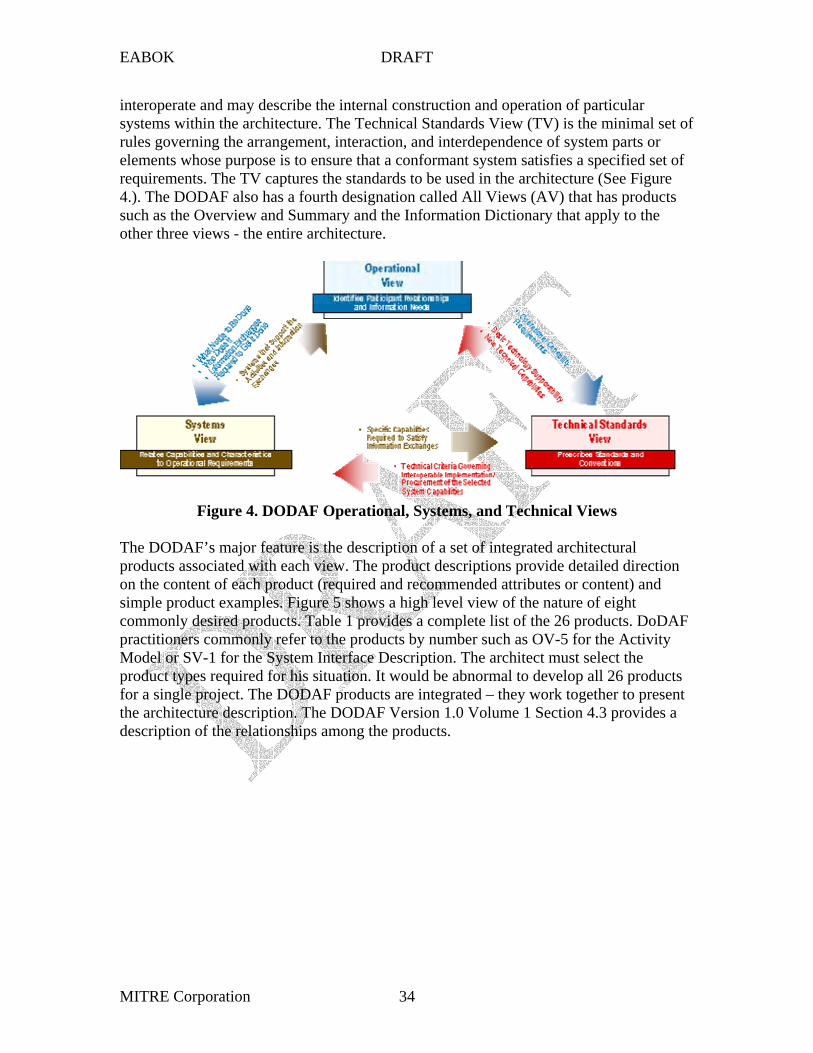
The DODAF is organized around three architectural views. The Operational View (OV) is a description of the tasks and activities, operational elements, and information exchanges required to accomplish DoD missions. The Systems View (SV) is a description, including graphics, of systems and interconnections providing for, or supporting, DoD functions. For a domain, the SV shows how multiple systems link and
MITRE Corporation 33
EABOK DRAFT
interoperate and may describe the internal construction and operation of particular systems within the architecture. The Technical Standards View (TV) is the minimal set of rules governing the arrangement, interaction, and interdependence of system parts or elements whose purpose is to ensure that a conformant system satisfies a specified set of requirements. The TV captures the standards to be used in the architecture (See Figure 4.). The DODAF also has a fourth designation called All Views (AV) that has products such as the Overview and Summary and the Information Dictionary that apply to the other three views - the entire architecture.
Figure 4. DODAF Operational, Systems, and Technical Views
The DODAF’s major feature is the description of a set of integrated architectural products associated with each view. The product descriptions provide detailed direction on the content of each product (required and recommended attributes or content) and simple product examples. Figure 5 shows a high level view of the nature of eight commonly desired products. Table 1 provides a complete list of the 26 products. DoDAF practitioners commonly refer to the products by number such as OV-5 for the Activity Model or SV-1 for the System Interface Description. The architect must select the product types required for his situation. It would be abnormal to develop all 26 products for a single project. The DODAF products are integrated – they work together to present the architecture description. The DODAF Version 1.0 Volume 1 Section 4.3 provides a description of the relationships among the products.
MITRE Corporation 34

EABOK DRAFT
OR
Trii )
(
OV-5
( i i )
iOV-2
HQ
DP
( i )
/
ivi i
Figure 5. Eight Commonly Used DODAF Products
Table 1.
Systems Interface Description SV-1
System Node
Communications Path System
System Node
System
System
System Node
System
Technical Standards Profile TV-1
Operational Information Exchange Matrix
OV-3
Producing Node
Producing Activity
Receiving Node
Receiving Activity
Communications Needline
Information Exchanged
IEM
Also Includes: ggering Event Descript on, ‘Properties’,
Performance, Security
Service Area Service Standard
Applications Software
Data Document XML 1.0 Interchange Interchange
Overview and Summary Information
(AV-1)
Integrated Dictionary (AV-2
Dictionary allows capture of Arch definitions, relationships, attributes,
rules
Business Process)
Operational Activity Model
Analyze Market
Data Report Outputs
Business Organ zat on
Operational Node Connectivity Descript on
Field Office
Center
Phone e-mail
Phone e-mail T3 Line, Satellite
Phone E-mail Inputs
Bus ness Concept
High-Level Operational Concept Graphic
OV-1
Importer/ExporterBroker
SAFE, LEGAL, OPEN TRADE
Carriers Goods Activity 1 Act ty 2 Act vity 3
Activity 4 Activity 5
Activity Hierarchy
DODAF Architecture Products
Applicable View
Framework Product Framework Product Name General Description
All Views AV-1 Overview and Summary Information
Scope, purpose, intended users, environment depicted, analytical findings
All Views AV-2 Integrated Dictionary Data repository with definitions of all terms used in all products
Operational OV-1 High-Level Operational Concept Graphic
High-level graphical/ textual description of operational concept
Operational OV-2 Operational Node Connectivity Description
Operational nodes, operational activities performed at each node, connectivity and information exchange needlines between nodes
Operational OV-3 Operational Information Exchange Matrix
Information exchanged between nodes and the relevant attributes of that exchange
Operational OV-4 Organizational Relationships Chart
Organizational, role, or other relationships among organizations
Operational OV-5 Operational Activity Model Operational Activities, relationships among activities, inputs and outputs. Overlays can show cost, performing nodes, or other pertinent information
Operational OV-6a Operational Rules Model One of the three products used to describe operational activity sequence and timing - identifies business rules that constrain operation
MITRE Corporation 35

EABOK DRAFT
OV-6c
OV-7
SV-1
SV-2
SV-3
SV-4
SV-5
SV-6 Matrix
SV-7 Parameters Matrix )
SV-8
SV-9
SV-10a
SV-10b
SV-10c
SV-11
TV-1 Profile
TV-2
Applicable View
Framework Product Framework Product Name General Description
Operational OV-6b Operational State Transition Description
One of three products used to describe operational activity sequence and timing - identifies business process responses to events
Operational Operational Event-Trace Description
One of three products used to describe operational activity sequence and timing - traces actions in a scenario or sequence of events and specifies timing of events
Operational Logical Data Model Documentation of the data requirements and structural business process rules of the Operational View.
Systems Systems Interface Description
Identification of systems and system components and their interconnections, within and between nodes
Systems Systems Communications Description
Systems nodes and their related communications lay-downs
Systems Systems-Systems Matrix Relationships among systems in a given architecture; can be designed to show relationships of interest, e.g., system-type interfaces, planned vs. existing interfaces, etc.
Systems Systems Functionality Description
Functions performed by systems and the information flow among system functions
Systems Operational Activity to Systems Function Traceability Matrix
Mapping of systems back to operational capabilities or of system functions back to operational activities
Systems Systems Data Exchange Provides details of systems data being exchanged between systems
Systems Systems Performance Performance characteristics of each system(s) hardware and software elements, for the appropriate timeframe(s
Systems Systems Evolution Description
Planned incremental steps toward migrating a suite of systems to a more efficient suite, or toward evolving a current system to a future implementation
Systems Systems Technology Forecast
Emerging technologies and software/hardware products that are expected to be available in a given set of timeframes, and that will affect future development of the architecture
Systems Systems Rules Model One of three products used to describe systems activity sequence and timing—Constraints that are imposed on systems functionality due to some aspect of systems design or implementation
Systems Systems State Transition Description
One of three products used to describe systems activity sequence and timing—Responses of a system to events
Systems Systems Event-Trace Description
One of three products used to describe systems activity sequence and timing -- System-specific refinements of critical sequences of events and the timing of these events
Systems Physical Schema Physical implementation of the information of the Logical Data Model, e.g., message formats, file structures, physical schema
Technical Technical Standards Extraction of standards that apply to the given architecture
Technical Technical Standards Forecast
Description of emerging standards that are expected to apply to the given architecture, within an appropriate set of timeframes
The DODAF is published in three volumes. Volume I: Definitions and Guidelines explains the value of architectures, provides an overview of the framework, describes how the views and products relate to each other, relates products to their use, provides principles for describing architectures, presents a six step process for building the EA (See EABOK section on process), and discusses the C4ISR Core Architecture Data Model (CADM) and repository issues. Volume II contains the product descriptions
MITRE Corporation 36

EABOK DRAFT
including the attributes required and recommended for each product. Volume III is called the Deskbook. It provides architecture guidance on the development and use of the EA, use of UML techniques, incorporating security into the architecture, use of the EA in Capital Planning and Investment Control (CPIC), and tools. It does not address the transition plan extensively.
As a framework that has been revised twice over an extended period of time, the DODAF contains considerable supplemental and explanatory material relating to the Program Objectives Memorandum (POM) process, OMB reference models, UML, architecture repositories, and other topics.
:
TEAF)
View organize and define the standards to be used in the agency.
Editor’s CommentMany novice EA practitioners comment that they find the DODAF too complex for a starting point to build an enterprise architecture. Others practitioners find the DODAF a good source of product description information to get them started. Guidance is needed to know which products to begin with depending on the needs of the situation, how the products fit together, and what level of detail to include.
3.1.3.3 Treasury Enterprise Architecture Framework (
The TEAF builds on the Zachman EA Framework, the FEAF, and the C4ISR (now the DODAF) frameworks. It was published in July 2000 as guidance to the Department of the Treasury and its bureaus. It includes not only an EA framework to organize and structure EA information with a prescribed set of products, but also recognizes the need for strategic direction to determine what the target EA must support, requires a transition strategy to show how the EA will evolve to support future capabilities, and provides principles to define the characteristics of the target EA. The TEAF relates the EA to the enterprise life cycle, identifies issues associated with basic EA activities, discusses the need for Configuration Management and a repository, and provides guidance on architecture management roles and responsibilities.
Figure 6 shows how the TEAF is divided into three parts - direction, description, and accomplishment - and the products for each part. The EA Description part is a matrix somewhat like Zachman’s. Its columns are four architectural views – Functional, Information, Organizational, and Infrastructure. Its rows are four perspectives – Planner, Owner, Designer, and Builder. Figures 7 and 8 provide definitions of these terms. The TEAF does not see views as mutually exclusive. The TEAF prescribes products for each matrix cell. Many of the products are based on DODAF products. The TEAF addresses security in the Information Assurance Policy and the Information Assurance Trust Model. The Technical Reference Model and Standards Profile products in the Infrastructure
The TEAF benefited from the earlier work of the Zachman, FEAF, and C4ISR (DODAF) frameworks by recognizing the end-to-end nature (strategic planning, investment, development, transition) of an EA and providing product specifications, many of which
MITRE Corporation 37

Esse
ntia
lW
ork
Prod
ucts
Supp
ortin
gW
ork
Prod
ucts
Legi
slat
ion
& D
irect
ives
Age
ncy
Polic
ies
Stra
tegi
cPl
ans
Ente
rpris
ePr
inci
ples
Info
rmat
ion
Ass
uran
cePo
licy
Ente
rpris
eR
equi
rem
ents
Ente
rpris
eA
rchi
tect
ure
Roa
dmap
Ente
rpris
eTr
ansi
tion
Stra
tegy
Fore
cast
s
Dat
a C
RU
D M
atric
es
Logi
cal D
ata
Mod
el
Bus
ines
s Pr
oces
s/Sy
stem
Fun
ctio
n M
atrix
Even
t Tra
ce D
iagr
ams
Stat
e C
hart
s
Syst
emFu
nctio
nalit
yD
escr
iptio
n
Phys
ical
Dat
a M
odel
Mis
sion
&Vi
sion
Stat
emen
tsIn
form
atio
nD
ictio
nary
Org
aniz
atio
n C
hart
Tech
nica
l Ref
eren
ceM
odel
Info
rmat
ion
Exch
ange
Mat
rix(C
once
ptua
l)
Nod
e C
onne
ctiv
ityD
escr
iptio
n(C
once
ptua
l)
Act
ivity
Mod
el
Info
rmat
ion
Ass
uran
ceTr
ust M
odel
Syst
em In
terf
ace
Des
crip
tion
Leve
l 1
Info
rmat
ion
Ass
uran
ceR
isk
Ass
essm
ent
Nod
e C
onne
ctiv
ityD
escr
iptio
n(L
ogic
al)
Syst
em In
terf
ace
Des
crip
tion
Leve
ls 2
& 3
Nod
e C
onne
ctiv
ityD
escr
iptio
n(P
hysi
cal)
Syst
em In
terf
ace
Des
crip
tion
Leve
l 4
Syst
em P
erfo
rman
cePa
ram
eter
s M
atrix
Stan
dard
s Pr
ofile
Info
rmat
ion
Exch
ange
Mat
rix(L
ogic
al)
Info
rmat
ion
Exch
ange
Mat
rix(P
hysi
cal)
Esse
ntia
lW
ork
Prod
ucts
Supp
ortin
gW
ork
Prod
ucts
Info
rmat
ion
Ass
uran
cePo
licy
Ente
rpris
eA
rchi
tect
ure
Roa
dmap
Ente
rpris
eTr
ansi
tion
Stra
tegy
Fore
cast
s
Org
aniz
atio
n C
hart
Info
rmat
ion
Exch
ange
Mat
rix(C
once
ptua
l)
Nod
e C
onne
ctiv
ityD
escr
iptio
n(C
once
ptua
l)
Info
rmat
ion
Exch
ange
Mat
rix(L
ogic
al)
Info
rmat
ion
Exch
ange
Mat
rix(P
hysi
cal)
EABOK DRAFT
MITRE Corporation 38
had already been tested in the field. It attempts to expand and improve the guidance to the architect. Today the TEAF is not actively supported.
EA
Des
crip
tion
EA
Acc
ompl
ishm
ent
EAD
irect
ion
Oth
er
Res
ourc
es
Planner Perspective
Owner Perspective
Designer Perspective
Builder Perspective
Func
tiona
lVi
ew
Infr
astr
uctu
re
View
O
rgan
izat
iona
l Vi
ew
Info
rmat
ion
View
Esse
ntia
l W
ork
Prod
ucts
Su
ppor
ting
Wor
k Pr
oduc
ts
EAD
escr
iptio
nEA
Acc
ompl
ishm
ent
EAD
irect
ion
Oth
erR
esou
rces
Legi
slat
ion
& D
irect
ives
Age
ncy
Polic
ies
Stra
tegi
c Pl
ans
Ente
rpris
e Pr
inci
ples
En
terp
rise
Prin
cipl
es
Info
rmat
ion
Ass
uran
ce
Polic
y
Ente
rpris
e R
equi
rem
ents
Ente
rpris
e A
rchi
tect
ure
Roa
dmap
Ente
rpris
e Tr
ansi
tion
Stra
tegy
Fore
cast
s Planner
PerspectiveOwner
PerspectiveDesigner
PerspectiveBuilder
Perspective
Func
tiona
lVi
ewIn
fras
truc
ture
View
Org
aniz
atio
nal
View
Info
rmat
ion
View
Dat
a C
RU
D M
atric
es
Logi
cal D
ata
Mod
el
Bus
ines
s Pr
oces
s/
Syst
em F
unct
ion
Mat
rix
Even
t Tra
ce D
iagr
ams
Stat
e C
hart
s
Syst
em
Func
tiona
lity
Des
crip
tion
Phys
ical
Dat
a M
odel
Mis
sion
& V
isio
n St
atem
ents
In
form
atio
n D
ictio
nary
O
rgan
izat
ion
Cha
rt
Tech
nica
l Ref
eren
ce
Mod
el
Info
rmat
ion
Exch
ange
Mat
rix
(Con
cept
ual)
Nod
e C
onne
ctiv
ity
Des
crip
tion
(Con
cept
ual)
Act
ivity
Mod
el
Info
rmat
ion
Ass
uran
ce
Trus
t Mod
el
Syst
em In
terf
ace
Des
crip
tion
Leve
l 1
Info
rmat
ion
Ass
uran
ce
Ris
k A
sses
smen
t
Nod
e C
onne
ctiv
ity
Des
crip
tion
(Log
ical
)
Nod
e C
onne
ctiv
ityD
escr
iptio
n(L
ogic
al)
Syst
em In
terf
ace
Des
crip
tion
Leve
ls 2
& 3
Nod
e C
onne
ctiv
ity
Des
crip
tion
(Phy
sica
l)
Syst
em In
terf
ace
Des
crip
tion
Leve
l 4
Syst
em P
erfo
rman
ce
Para
met
ers
Mat
rix
Stan
dard
s Pr
ofile
Info
rmat
ion
Exch
ange
Mat
rix
(Log
ical
)
Info
rmat
ion
Exch
ange
Mat
rix
(Phy
sica
l)
Figure 6. The TEAF Work Products for EA Direction, Description, and Accomplishment

Business functions,processes, andactivities that capturemanipulate, andmanage the businessinformation tosupport businessoperations
All informationneeded to performenterprise businessoperations andthe relationshipsamong thatinformation
The organizationalstructure of theenterprise, majoroperations performedby organizations,types of workers,work locations, andthe distribution of theorganizations tolocations
The hardware,software, networks,telecommunications,and general servicesconstituting theoperating environ-ment in whichbusiness applica-tions operate
The perspective focusing on strategic plans, enterprise-level processes, keyinformation and infrastructure important to the enterprise, and the structure of theorganization and its operating locations
The perspective focusing on the logical business process design, logical information model, component and application design, and system distributionand deployment approach
The perspective considering the constraints of tools, technology, and materials.The builder must translate the designer’s specifications into plans for physicalimplementation. The builder also focuses on integration and test.
The perspective focusing on conceptual-level models of business processes, information, business logistics, and IT infrastructure
EABOK DRAFT
Functional View
Infrastructure View
Organizational View
Information
Views
FunctionalView
InfrastructureView
OrganizationalView
Information
Views
ViewView
Pers
pect
ives
Planner
Owner
Designer
Builder
Pers
pect
ives
Planner
Owner
Designer
Builder
Business functions, processes, and activities that capture manipulate, and manage the business information to support business operations
All information needed to perform enterprise business operations and the relationships among that information
The organizational structure of the enterprise, major operations performed by organizations, types of workers, work locations, and the distribution of the organizations to locations
The hardware, software, networks, telecommunications, and general services constituting the operating environment in which business applications operate
Figure 7. TEAF Core Views
Functional View
Infrastructure View
Organizational View
Information View
Views
Pers
pect
ives
Planner
Owner
Designer
Builder
FunctionalView
InfrastructureView
OrganizationalView
InformationView
Views
Pers
pect
ives
Planner
Owner
Designer
Builder
The perspective focusing on strategic plans, enterprise-level processes, key information and infrastructure important to the enterprise, and the structure of the organization and its operating locations
The perspective focusing on the logical business process design, logical information model, component and application design, and system distribution and deployment approach
The perspective considering the constraints of tools, technology, and materials. The builder must translate the designer’s specifications into plans for physical implementation. The builder also focuses on integration and test.
The perspective focusing on conceptual-level models of business processes, information, business logistics, and IT infrastructure
Figure 8. TEAF Core Perspectives
MITRE Corporation 39

EABOK DRAFT
3.1.4 State and Industry-Sponsored Frameworks
3.1.4.1 National Association of State Chief Information Officers (NASCIO)
The state-sponsored National Association of State Chief Information Officers (NASCIO) Enterprise Architecture Development Tool-Kit V 2.0 approach has business, technology, and governance frameworks. Its governance framework contains descriptions of EA related positions, e.g., chief architect, organizational roles and structures, processes for governance (documentation, review, compliance, communication, framework vitality,
TOGAF)
The
As described on the TOGAF web site
and blueprint vitality). The extensive detail of the technology architecture is planned for a later version of the tool kit. There are many EA examples from state governments (e.g., Kentucky) developed using the NASCIO tool-kit available on the web.
3.1.4.2 The Open Group Architectural Framework (
TOGAF 8: Enterprise Edition provides an Architecture Development Method (ADM) as part of a framework for developing an enterprise architecture. The TOGAF was developed by consensus among members of The Open Group. Its method can be used with other frameworks or based on the information recommended in the TOGAF. TOGAF was originally based on the Technical Architecture Framework for Information Management (TAFIM) and includes a Technical Reference Model organizing service categories, standards information, a discussion of boundaryless information flow and Integrated Information Infrastructure Reference Model (III-RM) concepts, discussions on developing various architecture views such as business, security, and software, governance information, and templates to help readers get started.
‘There are four main parts to the TOGAF document. PART I: Introduction … provides a high-level introduction to some of the key concepts behind enterprise architecture and in particular the TOGAF approach.
PART II: Architecture Development Method is the core of TOGAF. It describes the TOGAF Architecture Development Method - a step-by-step approach to developing an enterprise architecture.
PART III: Enterprise Continuum describes the TOGAF Enterprise Continuum, a virtual repository of architecture assets, which includes the TOGAF Foundation Architecture, and the Integrated Information Infrastructure Reference Model.
PART IV: Resources comprises the TOGAF Resource Base - a set of tools and techniques available for use in applying TOGAF and the TOGAF ADM.’
3.1.4.3 Reference Model for Open Distributed Processing (RM-ODP) - FUTURE
This section will describe the RM-ODP framework if warranted. ISO standard ISO/IEC 10746-1: Reference Model – Open Distributed Processing (RM-ODP)
MITRE Corporation 40
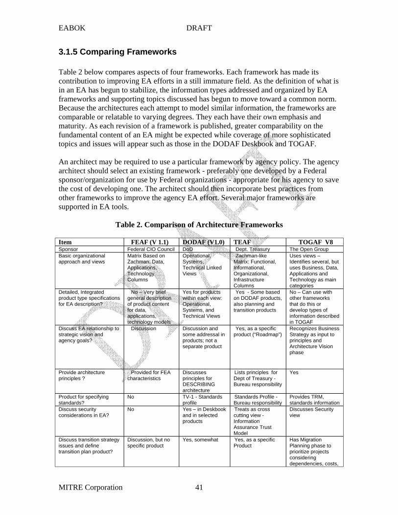
EABOK DRAFT
3.1.5 Comparing Frameworks
Table 2 below compares aspects of four frameworks. Each framework has made its contribution to improving EA efforts in a still immature field. As the definition of what is in an EA has begun to stabilize, the information types addressed and organized by EA frameworks and supporting topics discussed has begun to move toward a common norm. Because the architectures each attempt to model similar information, the frameworks are comparable or relatable to varying degrees. They each have their own emphasis and maturity. As each revision of a framework is published, greater comparability on the
supported in EA tools.
Item ) ( ) TEAF Sponsor
Matrix Based on
Applications,
Columns
Technical Linked
Zachman-like
Informational,
Infrastructure Columns
Identifies several, but
Applications and
categories
for EA description? general description
for data, applications,
wialso planning and
i
that do this or
iDiscuss EA relationship to strategic vision and
Discussion some addressal in products; not a
Recognizes Business
principles and Architecture Vision phase
Provide architecture principles ?
Provided for FEA istics
Discusses principles for
architecture
for
Bureau responsibility
ing standards?
No profile Bureau responsibility
Provides TRM,
Discuss security considerations in EA?
No and in selected products Information
Assurance Trust Model
Discusses Security view
issues and define Discussion, but no specific product Product
Has Migration Planning phase to prioritize projects considering dependencies, costs,
fundamental content of an EA might be expected while coverage of more sophisticated topics and issues will appear such as those in the DODAF Deskbook and TOGAF.
An architect may be required to use a particular framework by agency policy. The agency architect should select an existing framework - preferably one developed by a Federal sponsor/organization for use by Federal organizations - appropriate for his agency to save the cost of developing one. The architect should then incorporate best practices from other frameworks to improve the agency EA effort. Several major frameworks are
Table 2. Comparison of Architecture Frameworks
FEAF (V 1.1 DODAF V1.0 TOGAF V8 Federal CIO Council DoD Dept. Treasury The Open Group
Basic organizational approach and views Zachman: Data,
Technology
Operational, Systems,
Views
Matrix: Functional,
Organizational,
Uses views –
uses Business, Data,
Technology as main
Detailed, Integrated product type specifications
No – Very brief
of product content
technology models
Yes for products thin each view:
Operational, Systems, and Technical Views
Yes - Some based on DODAF products,
transition products
No – Can use w th other frameworks
develop types of information described n TOGAF
agency goals?
Discussion and
separate product
Yes, as a specific product (“Roadmap”) Strategy as input to
characterDESCRIBING
Lists principlesDept of Treasury -
Yes
Product for specify TV-1 - Standards Standards Profile - standards information
Yes – in Deskbook Treats as cross cutting view -
Discuss transition strategy
transition plan product?
Yes, somewhat Yes, as a specific
MITRE Corporation 41

EABOK DRAFT
Item FEAF (V 1.1) DODAF (V1.0) TEAF TOGAF V8 and benefits
Discuss EA Repository Mentions need for Yes Assigns agency the Issues? one responsibility Provide guidance on EA development process?
Minimal- refers to EAP text, generally outside scope – see Practical Guide
High level 6 step process
Some – develop EA strategy, EA roles and responsibilities, CM, investment
Yes – Architecture Development Method (ADM) forms ‘core’ of framework
management Maturity/Status Version 1.1 Sept
1999 – 2002 revision not
Two major revisions
Version 1 2000 – Currently on hold
Version 8.1 Had several revisions
completed – Currently on hold
Tool Support Popkin System Architect Plug in
Systems/Organizations Global Information Using Framework Grid (GIG);
CCIC2S
Comments
Provides
tailoring, and presents lessons learned.
Journal Vol 26, No 3, 1987.
/publications
References
Goicoechea, Ambrose, What is the Best EA Framework for your Customer? Criteria for EA Framework Selection and/or Tailoring, MITRE Corporation, October 2003. an overview of several frameworks, relates them to a methodology and criteria, discusses
Zachman, J.A., A Framework for Information Systems Architecture, IBM Systems
Zachman, J.A., and Sowa, J.F., Extending and Formalizing the Framework for Information Systems Architecture, IBM Systems Journal, Vol 31, No 3, 1992.
John Zachman Web Site: http://www.zifa.com - Has a bibliography of Zachman’s
Zachman Framework Tutorial: http://www.va.gov/oirm/architecture/EA/theory/tutorial.ppt
Office of Management and Budget, Circular No. A-130, Management of Federal Information Resources, November 30, 2002.
Federal Enterprise Architecture Framework (FEAF) Version 1.1, Federal CIO Council, September 1999.
DoD Architecture Framework Version 1.0 (Draft) aitc.aitcnet.org/dodfw
MITRE Corporation 42
EABOK DRAFT
Treasury Enterprise Architecture Framework (TEAF) Version 1, Department of the Treasury Chief Information Officer Council, July 2000.
Enterprise Architecture Development Tool-Kit, V 2.2, National Association of State Chief Information Officers (NASCIO), July 2002. (provides guidance on roles and governance) https://www.nascio.org/hotIssues/EA/
The Open Group Architecture Framework (TOGAF) Version 8 Enterprise Edition: http://www.opengroup.org/architecture/
ISO standard ISO/IEC 10746-1
(TBD)
(TBD)
(TBD)
as Kentucky.
Reference Model – Open Distributed Processing (RM-ODP) 1996, http://www.dstc.edu.au/Research/Projects/ODP/ref_model.html
FEAF Example Products: See the W900 Web Site
TEAF Example Products: See the W900 Web Site
DODAF Example Products: See the W900 Web Site
NASCIO Example Products: Examine the web sites for various state governments such
MITRE Corporation 43

EABOK DRAFT
3.2 Reference Models and Reference Architectures14
3.2.1 OMB Reference Models: The Federal Enterprise Architecture (FEA)15
Dr. Paula Hagan MITRE Corporation, Software Engineering Center
703 883 6518
3.2.1.1 Overview
16
service delivery. 17
for collaboration.
The Office of Management and Budget (OMB) Federal Enterprise Architecture (FEA) Program Management Office (FEA-PMO) describes the FEA as a business and performance-based framework for cross agency, government-wide improvement. The purpose of the FEA is to identify opportunities to simplify processes, re-use Federal IT investments, and unify work across the agencies and within the lines of business of the Federal Government, i.e., the focus is on performance, comparability, and reuse. The outcome of the effort will be a more citizen-centered, customer-focused government that maximizes technology investments to better achieve mission outcomes. The OMB views the Federal Enterprise Architecture not as a model, but as a program built into the annual budget process to repeatedly and consistently improve all aspects of government
Because of the newness of the OMB Reference Models, this section provides an in-depth explanation of the models. For the complete details, the reader should examine the references.
The FEA is composed of five interrelated reference models as portrayed by OMB in Figure 1. The models are designed to facilitate cross-agency analysis and opportunities
14 Revised January 31, 2004 15 Much of the factual material in this document has been taken directly from the OMB references cited for the BRM, PRM, SRM, and TRM. 16 The Service Component Reference Model (SRM) Version 1.0 Page 33. 17 The Business Reference Model Version 2.0 Page 1.
MITRE Corporation 44

EABOK DRAFT
• Li i
ili
lity i
i i i
i(Citi
i ifi
i
18
sub-functions.
define standards and specifications.
Business Reference Model (BRM) nes of Bus ness
• Agencies, Customers, Partners
Service Component Reference Model (SRM) • Service Layers, Serv ce Types • Components, Access and De very Channels
Technical Reference Model (TRM) • Service Component Interfaces, Interoperabi• Technolog es, Recommendations
Data Reference Model (DRM) • Bus ness-focused data standard zat on • Cross-Agency Information exchanges
Business-Drven Approach
zen-Centered Focus)
Performance Reference Model (PRM)
• Government-wide Performance Measures & Outcomes • Line of Bus ness-Spec c Performance Measures & Outcomes
Component-Based Arch
tectures
Figure 1. Five Reference Models Compose the FEA
The four models (BRM, PRM, SRM, and TRM) published at this writing each use a hierarchical structure to develop and refine classification categories for their respective domains. The BRM hierarchy identifies Business Areas, Lines of Business (LOB) and
Example of sub-functions are Legal Investigation, Worker Safety, and Goods Acquisition. The PRM defines Measurement Areas such as Customer Results, Measurement Categories such as Timeliness, and Indicators such as percent of calls answered within 15 seconds. The SRM classifies service components with respect to how they support business or performance objectives. The SRM identifies seven service domains like Customer Services or Business Management Services, then defines service types and associated components for each. A component is a self contained business process or service with predetermined functionality such as Call Center Management, Case/Issue Management, or Data Recovery. The lower levels of the TRM hierarchy
These classification categories allow OMB and agencies to separate business functions, relate performance measures and service components to those functions, and relate standards and specifications to the service components needed to support the business functions. OMB is interested in uniquely separating business functions to identify redundant efforts and potential cross agency investments. The President’s Management Agenda calls for the development of a common set of performance measures across the government. The PRM supports that goal by identifying categories of measures for which
18 Taken from OMB Reference Models materials
MITRE Corporation 45

Program Admin ComplianceServices to Citizens
Public Asset ManagementMarketable Asset ManagementDefense & Nat’l Security OpsDiplomacy & Foreign RelationsDisaster ManagementDomestic EconomyEducationEnergy ManagementInsurancePublic HealthRecreation & National Resource sSocial ServicesR&D & Science
Regulated Activity ApprovalConsumer Safety
Environmental ManagementLaw Enforcement
LegalRevenue Collection
Trade (Import/Export)Transportation
Workforce Management
Support Delivery of ServicesLegislative ManagementBusiness Management of InformationIT ManagementPlanning and Resource AllocationRegulatory Management
Controls and OversightPublic AffairsInternal Risk Management and MitigationFederal Financial Assistance
People Technology
CustomerResults
BusinessResults
Other Fixed Assets
EABOK DRAFT
agencies will collaboratively define specific indicators associated with business functions identified in the BRM.
The Agency Chief Architect and other planners can identify efforts from other agencies through the BRM, SRM, and TRM to determine if another agency has already developed a capability for a needed business function that the agency could potentially reuse as portrayed in Figure 2.
Internal Operations/Infrastructure Human Resou rce s Fi nancial Management Ad m in S up ply Chain M a na g e m e n t
Huma n Re sou rce s Fina ncial Management Ad min Supply Cha in Management
Inter-Agency Intra-Agency
Program Admin Compliance Services to Citizens
Public Asse t Management Ma rketable Asse t Management De fe n se & Na t’ l S e cu ri t y Op s Dipl omacy & Foreign Re la tions Di saster Management Do m e stic Eco no m y Educati on Energy Manageme nt In su r a n ce Publi c He alth Re crea tion & Na tiona l Resource s So cial Ser vices R&D & Scie nce
Re gula ted Activity Ap proval Con sume r Sa fe ty
Environme ntal Ma na geme nt La w Enfor ceme nt
Legal Reve nue Collection
Tra de (Import/Ex port) Tra nsp o rta tion
W orkforce Ma na ge me nt
Support Delivery of Services
Internal Operations/InfrastructureInternal Operations/Infrastructure
Legisla tive Management Bu siness Management of Info rm ati on IT Management Planning a nd Re source Al locati on Regula tory Managem ent
Co ntrol s and Oversigh t P u b l ic Affa irs Inte rna l Risk M ana ge me nt and Mi tigati on Fe dera l Fina ncial Assi sta nce
Human Resource s Financial ManagementAdmin Supply Chain Management
Human Resource s Financial Management Admin Supply Chain Management
Inter-Agency Intra-Agency
1 A new performance gap is identified. How do I improve performance?
2 Is the business function being performed across the Government?
FEA Business Reference Model (BRM)
3
4
Create Service Component, Advance FEA Capabilities
Implement Component-based Architecture and TRM standards
Service Level Agreements
6
5
Will the Components support the business need? What modifications are needed?
What Service Components are being used to support the business and process?
What performance measures, and outcomes are the Service Components supporting?
Processes and ActivitiesProcesses and Activities
People Technology
Customer Results
Business Results
Strategic Outcomes
Other Fixed Assets
Value
Performance Reference Model (PRM)
Service Component Reference Model (SRM)
Yes
No
Buy, Build, Borrow
Exhibit 300’s
Same Business Process?
Support ServicesSecurity Management Systems Management Forms
Communication Collaboration
Search
Customer Services
Process Automation Services
Business Management Services
Digital Asset Services
Business Analytical Services
Back Office Services
Customer Preferences Customer Relationship M anage ment (CRM)
Data Management Human Resources Financial Management
Assets / Materials Management Development and Integration
Human Capital / Workforce Management
Analysis and Statistics Business Intellige nce
Visualization Reporting
Content Management Knowledge Management
Docume nt M anage me nt Records Management
Management if Process Organizational Management
Supply Chain Management
Investment Management
Tracking and Workflow Routing and Automation
Customer Initiated Assistance
What Access Channels can be used to access the Component? (i.e., PDA, Web Service, etc.)
Service Access and Delivery Access Channels Web Browser Wireless/PDA Device Collaboration / Communication Other Electronic Channels
Delivery Channels Internet, Intranet Extranet Peer to Peer (P2P)Virtual Private Network (VPN)
Service Requirements Legislative / Compliance Authentication / Single Sign-On Hosting
Service Transport Netw ork Services
Transport
Support Platforms Wireless / M obile PlatformIndependent (J2EE)Platform Dependent (.NET)
Database / Storage Database Storage Devices
Delivery Servers Web, M edia Application Portal
Software EngineeringIntegrated Development Environment (IDE) Software ConfigurationManagement (SCM)Testing Management, Modeling
Hardware / Infrastructure Servers Computers
Embedded Technology Devices
Peripherals WAN/LAN
Network Devides/Standards Video Conferencing
SecurityCertificates / Digital Signature Supporting Security Services
Data Interchange Data Exchange
Presentation / Interface Static Display Dynamic Server – Side Display Content Rendering Wireless / Mobile / Voice
Business Logic PlatformIndependent Platform Dependent
Data Management Database Connectivity
Reporting and Analysis
Integration Middleware Database Access Transaction Processing Object Request Broker
InteroperabilityData Format / Classification Data Types / Validation Data Transformation
Interface Service Discovery
Service Description / Interfae
Service Platform and Infrastructure
Component Framework
Service Interface and Integration
Technical Reference Model (TRM)
Figure 2. Using the Reference Models in EA Planning19
The Chief Architect can use the SRM and TRM to speed component-based architecture solutions by identifying Service Components associated with a business function through the SRM, then identify the e-business pattern associated with the agency needs and finally locating products that can provide the capability for that pattern through the TRM. (See the reference on e-business patterns for more on patterns.) Figure 3 shows the high-level relationships between the five models.
19 Taken from OMB Reference Models materials
MITRE Corporation 46

EABOK DRAFT
MITRE Corporation 47
Lines of BusinessCategories of Business functions
Outcomes, Measures, MetricsMeasure example: Processes - Cycle Time and Resource TimeIndicator Example: Number of satisfied customers
Sub function Example:Project Planning
System Development
Categories of capabilities or Service ComponentsExample: Business management services-Management of Process - Requirements Management
Standards and specificationsorganized by service area and category
Agency specifiesmeasure detail for business function
Service Components
support business function
Standard or Specificationfor Specific Component
DRM(future)
Identifies data categories
and small set of schemas
Used by business process &component
Processes and Activities
Human Capital Technology
ResultsMission &Bus. Reslts Results
CustomerResults
Strategic Outcomes
Other Fixed Assets
INPUTS
Service Types
Components
PRM
TRM SRM
Management of Government Resources
Support DeliveryOf Services
Services forCitizens
Mode ofDelivery
Defen se and N ational Securit yHomelan d SecurityIntellig en ce Op eration sLaw EnforcementIntrnational Affairs and C ommerceLitigation and Judicial ActivitiesCorrection al Activities
Edu cationEn erg yHealth
Tran sport ationIncome Securit y
Environ mental Manag ementNatural R esources
Disaster Manag ementCommun it y and So cial Services
Economic D ev elopmentW orkforce M an agement
Gen eral Scien ce and Inn ovation
Government Service D eliveryDirect Services for Citizen sKno wledg e Creation and MgmtPublic Good s Creatio n and MgmtRegulatory Co mplian ce and Enforcement
Finan cial VehiclesFed eral Fin an cial Assistance
Credit and Insu ran ceTransfers to States and
Local Gov ernment s
Legislative R elationsPublic AffairsRegulatory D evelo pmentPlanning an d R esource Allo cation
Gen eral Gov ernment
Controls and Oversig htRevenue Collection
Intern al Risk Man ag ement and Mitigation
Supply C hain Man ag ement
Human R esource M an ag ement
Finan cial Management
Ad ministrative M an ag ement
Information an d Tech nolog y Management
BRM
Support ServicesSecurity ManagementSystems ManagementForms
CommunicationCollaboration
Search
Customer Services
Process Automation Services
Business Management Services
Digital Asset Services
Business Analytical Services
Back Office Services
Customer PreferencesCustomer Relationship Management (CRM)
Data ManagementHuman ResourcesFinancial Management
Assets / Materials ManagementDevelopment and Integration
Human Capital / Workforce Management
Analysis and StatisticsBusiness Intelligence
VisualizationReporting
Content ManagementKnowledge Management
Document ManagementRecords Management
Management if ProcessOrganizational Management
Supply Chain ManagementInvestment Management
Tracking and Workflow Routing and Automation
Customer Initiated Assistance
Service Domains
Service Access and Delivery
Access Ch ann elsW eb Bro wserW ireless/PD A DeviceCollaboration / Co mmunicationOther Electronic C hannels
Delivery Ch ann elsIntern et, Intran etExtranetPeer to Peer (P2P)Virtual Pr ivate Network ( VPN)
Service R equirement sLegislative / Co mplian ceAuth entication / Single Sign-OnHosting
Service Tran sportNet work Services
Tran sport
Supp ort PlatformsW ireless / MobilePlatform Ind ep endent (J2EE)Platform Depen dent (.NET)
Datab ase / Storag eDatab aseStorage Devices
Delivery ServersW eb, MediaAp plicationPortal
Software Engin eeringIntegrated D ev elopment Environment (ID E)Software Co nfiguration Man ag em ent (SCM)Testing Man ag ement, Modeling
Hardware / InfrastructureSer vers C omputers
Embedded T echnology DevicesPeri pheralsWAN/LAN
Network D evi des/StandardsVideo C onfer encing
Secur it yCertificates / Digital Sign atureSupp orting Securit y Services
Data Interch ang eData Exchange
Presentation / InterfaceStatic DisplayDynamic Ser ver – Side DisplayContent Renderi ngWirel ess / Mobil e / Voice
Busin ess LogicPlatform Indep end entPlatform Dependent
Data ManagementDatabase C onnecti vityReporting and Anal ysis
IntegrationMiddlewareDatab ase AccessTran saction ProcessingObject R equ est Broker
Interop erabilityData Format / ClassificationData T yp es / Valid ationData Transformation
InterfaceSer vice D iscovery
Ser vice D escription / Interfae
Service Platform andInfrastructure
Component Framework
Service Interface and Integration
Figure 3. Relationships Among the OMB Reference Models
OMB will use the FEA to analyze investments in information technology to identify • What agencies share common business functions, processes, and activities • What budget requests support duplicative business functions and information
systems • Where the government is investing money on redundant capabilities, including
work under the human capital strategy • How IT investment is supporting the achievement of performance goals.
OMB will enforce the use of the FEA by requiring agencies to link or relate their proposed initiatives to the reference models in their 300 submissions required by OMB Circular A-11. Agencies must explain alignment with the BRM in submissions for FY 2005 funding. They must identify
• All Lines of Business and Sub-Functions from the FEA Business Reference Model that IT investment supports II.A.1.E.
• What types of data will be used in the project II.A.2.A. • Relationship to the Service Component Reference Model Section of the FEA.
Include a discussion of the components included in the major IT investment. II.A.3.A.
• Relationship to the Technical Reference Model Section of the FEA. Identify each Service Area, Service Category, Service Standard, and Service Specification that

EABOK DRAFT
collectively describes the technology supporting the major IT investment. II.A.3.C.
The reader should consult the latest version of OMB A-11 for the current guidance.
3.2.1.2. Model Overview Descriptions
3.2.1.2.1 Business Reference Model (BRM)
The BRM provides a functional as opposed to organizational (i.e., by Department) way of
shows the Service Areas and Lines of Business (LOBs).
Mode of
i
li
Figure 4. BRM Version 2.0 Business Areas and Lines of Business
looking at government operations that allows identification and comparison of functions across agencies. The BRM three tier hierarchy has business areas, lines of business (LOB) within the business areas, and sub-functions for the lines of business. Figure 4
Management of Government Resources
Support Delivery Of Services
Services for Citizens
Delivery
Defense and National Security Homeland Security Intelligence Operations Law Enforcement Intrnational Affairs and Commerce Litigation and Judicial Activities Correctional Activities
Education Energy Health
Transportation Income Security
Environmental Management Natural Resources
Disaster Management Community and Social Services
Economic Development Workforce Management
General Sc ence and Innovation
Government Service De very Direct Services for Citizens Knowledge Creation and Mgmt Public Goods Creation and Mgmt Regulatory Compliance and Enforcement
Financial Vehicles Federal Financial Assistance
Credit and Insurance Transfers to States and
Local Governments
Legislative Relations Public Affairs Regulatory Development Planning and Resource Allocation General Government
Controls and Oversight Revenue Collection
Internal Risk Management and Mitigation
Supply Chain Management
Human Resource Management Financial Management
Administrative Management
Information and Technology Management
The four Business Areas are Services for Citizens, Mode of Delivery, Support Delivery of Services, and Management of Government Resources. A Mode of Delivery like ‘Credit and Insurance’ is a way to deliver a service like ‘Economic Development’ to the citizen. Each Line of Business has associated sub-functions. For example, Workforce Management has the sub-functions Training and Employment, Labor Rights Management, and Worker Safety. Figure 5 shows sub-functions associated with the Services for Citizens LOBs from Version 2.0. The OMB Reference Model writeup
MITRE Corporation 48

EABOK DRAFT
provides diagrams of all business areas and their LOBs, and associated sub-functions and a few lines of description of each sub-function.
National i l lli i Di
and Planning
i i l i
i l il i ion i
Exhibition
Heal i
igation and i
Litigation
ional ivities ii
itiServices For
Citizens
Defense and Secur ty Home and Security
Strategic National and Theater Defense
Operational Defense Tactical Defense
Border and Transportation Security
Key Asset and Critical Infrastructure Protection
Catastrophic Defense
Inte gence Operat ons
TBD
saster Management
Disaster Monitoring and Prediction
Disaster Preparedness
Disaster Repair and Restore Emergency Response
Internat onal Affa rs and Commerce
Foreign Affairs International Development and
Humanitarian Aid Global Trade
Water Resource Management Conservation, Marine, and
Land Management Recreational Resource
Management and Tourism Agricultural Innovation
and Services
Natura Resources Energy
Energy Supply Energy Conservation and
Preparedness Energy Resource Management Energy Production
Env ronmental Management
Environmental Monitoring and Forecasting
Environmental Remediation Pollution Prevention
and Control
Econom c Deve opment Commun ty and Socia Serv ces Transportat Educat on
Business and Industry Development
Industry Sector Income Stabilization
Intellectual Property Protection Financial Sector Oversight
Homeownership Promotion Community and Regional
Development Social Services Postal Services
Air Transportation Ground Transportation Water Transportation Space Operations
Elementary, Secondary, and Vocational Education
Higher Education Cultural and Historic
Preservation Cultural and Historic
Workforce Management th Income Secur ty Law Enforcement
Training and Employment Labor Rights Management Worker Safety
Illness Prevention Immunization Management Public Health Monitoring Health Care Services Consumer Health and Safety
General Retirement and Disability Unemployment Compensation Housing Assistance Food and Nutrition Assistance Survivor Compensation
Criminal Apprehension Criminal Investigation
and Surveillance Citizen Protection Crime Prevention Leadership Protection Property Protection Substance Control
LitJud cial Activities
Judicial Hearings Legal Defense Legal Investigation Legal Prosecution and
Resolution Facilitation
Correct Act General Sc ence And Innovat on
Criminal Incarceration Criminal Rehabilitation
Scientific and Technical Research and Innovation
Space Exploration and Innovation
Sub-functions Line of Business
BRM V 2.0 Services for C zens Business Area
Figure 5. Example Sub-Functions for Services For Citizens – BRM Version 2.0
In Version 1.0 of the BRM, the statement was made that the BRM had been normalized – lines of business and sub-functions did not overlap, a good feature for a mechanism designed to distinguish and separate for identifying overlap and redundancy. Figure 6 illustrates the BRM acting as a sorting mechanism for new initiatives.
MITRE Corporation 49
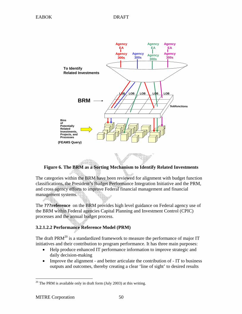
EABOK DRAFT
LOB LOB LOB
bfu ti s
EA
of
BRM
EA EA
)
The ???reference
processes and the annual budget process.
3.2.1.2.2 Performance Reference Model (PRM)
LOB LOB
Su nc on
Agency 300s
Agency 300s
Agency 300s
Agency
Bins
Potentially Related Investments, Projects, and Processes
To Identify Related Investments
Agency Agency
Agency 300s
(FEAMS Query
Figure 6. The BRM as a Sorting Mechanism to Identify Related Investments
The categories within the BRM have been reviewed for alignment with budget function classifications, the President’s Budget Performance Integration Initiative and the PRM, and cross agency efforts to improve Federal financial management and financial management systems.
on the BRM provides high level guidance on Federal agency use of the BRM within Federal agencies Capital Planning and Investment Control (CPIC)
The draft PRM20 is a standardized framework to measure the performance of major IT initiatives and their contribution to program performance. It has three main purposes:
• Help produce enhanced IT performance information to improve strategic and daily decision-making
• Improve the alignment - and better articulate the contribution of - IT to business outputs and outcomes, thereby creating a clear ‘line of sight’ to desired results
20 The PRM is available only in draft form (July 2003) at this writing.
MITRE Corporation 50
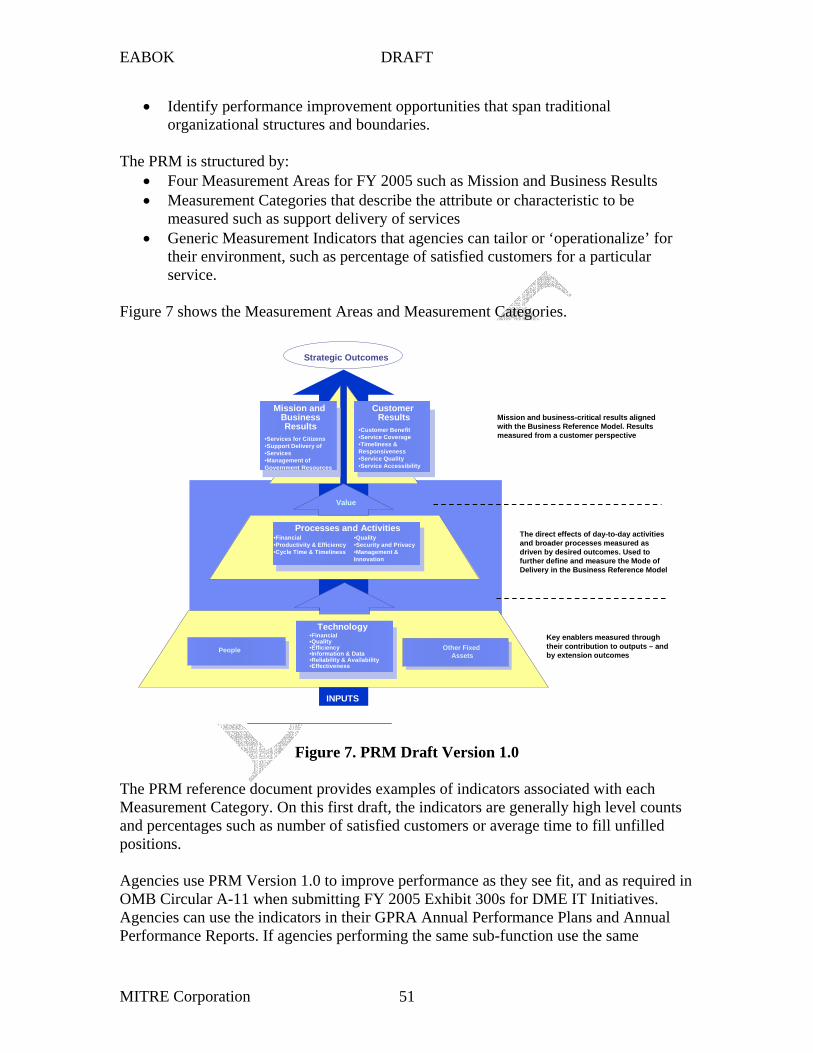
Processes and Activities
People Technology
Customer
Results
Business
Results
Other Fixed Assets
EABOK DRAFT
• Identify performance improvement opportunities that span traditional organizational structures and boundaries.
The PRM is structured by: • Four Measurement Areas for FY 2005 such as Mission and Business Results • Measurement Categories that describe the attribute or characteristic to be
measured such as support delivery of services • Generic Measurement Indicators that agencies can tailor or ‘operationalize’ for
their environment, such as percentage of satisfied customers for a particular service.
••••
•••
••
•••
•••
••••••
i
iwi
Figure 7. PRM Draft Version 1.0
Figure 7 shows the Measurement Areas and Measurement Categories.
Processes and Activities
People
Technology
Strategic Outcomes
Other Fixed Assets
INPUTS
Mission and Business Results
Services for Citizens Support Delivery of Services Management of
Government Resources
Customer Results
Customer Benefit Service Coverage Timeliness &
Responsiveness Service Quality Service Accessibility
Value
Financial Productivity & Efficiency Cycle Time & Timeliness
Quality Security and Privacy Management &
Innovation
Financial Quality Efficiency Information & Data Reliability & Availability Effectiveness
Key enablers measured through their contribution to outputs – and by extension outcomes
The d rect effects of day-to-day activities and broader processes measured as driven by desired outcomes. Used to further define and measure the Mode of Delivery in the Business Reference Model
Mission and bus ness-critical results aligned th the Business Reference Model. Results
measured from a customer perspective
The PRM reference document provides examples of indicators associated with each Measurement Category. On this first draft, the indicators are generally high level counts and percentages such as number of satisfied customers or average time to fill unfilled positions.
Agencies use PRM Version 1.0 to improve performance as they see fit, and as required in OMB Circular A-11 when submitting FY 2005 Exhibit 300s for DME IT Initiatives. Agencies can use the indicators in their GPRA Annual Performance Plans and Annual Performance Reports. If agencies performing the same sub-function use the same
MITRE Corporation 51

EABOK DRAFT
performance indicators or measures to assess their outputs and outcomes, the Government has a way to compare how effectively and efficiently agencies are performing similar functions. This is consistent with the President’s Management Agenda Budget and Performance Integration item.
3.2.1.2.3 Service Component Reference Model (SRM)
The SRM is a business driven, functional framework that classifies service components with respect to how they support business and/or performance objectives. A component is
be exposed through a business or technology service.”21 The SRM defines five levels of
which in turn sustain the BRM sub-functions.
“a self contained business process or service with predetermined functionality that may
component granularity, four of which are included in the SRM. Federated Component, Business Component System, Business Component, and Distributed Component are included; Language Class (e.g., COBAL) is not included. The conceptual hierarchy of these components is shown in Figure 9. The effective identification, assembly, and usage of components allow for aggregate services to be shared across agencies and governments. The services provide the functionality and execution of business processes
Federated Component
Business Component System Business Component System
Business Component
Distributed Components
Business Component
Distributed Components
Business Component
Distributed Components
Business Component
Distributed Components
Figure 9. Conceptual Hierarchy of Components showing Granularity
Some of the reasons the SRM was created are to:
21 SRM Version 1.0 Page 3.
MITRE Corporation 52

EABOK DRAFT
1) provide a framework that identifies service components and their relationships to the technology architecture of agencies, 2) classify, categorize, and recommend components for the reuse of business services and capabilities, and 3) align and leverage existing federal guidance and application/architecture recommendations.
The SRM is intended for use in discovering government-wide business and application Service Components in IT investments and assets. The SRM is business-driven and
( )
classifies Service components with respect to how they support business and/or performance objectives.
The SRM’s three level hierarchical structure to support categorization consists of Service Domains, Service Types, and Components. Figure 10 shows the SRM structure listing the domain services and their supporting service types. The service domains are differentiated by the business-oriented capability they represent.
Support Services Security Management Systems Management Forms
Communication Collaboration
Search
Customer Services
Process Automation Services
Business Management Services
Digital Asset Services
Business Analytical Services
Back Office Services
Customer Preferences Customer Relationship Management CRM
Data Management Human Resources Financial Management
Assets / Materials Management Development and Integration
Human Capital / Workforce Management
Analysis and Statistics Business Intelligence
Visualization Reporting
Content Management Knowledge Management
Document Management Records Management
Management if Process Organizational Management
Supply Chain Management Investment Management
Tracking and Workflow Routing and Automation
Customer Initiated Assistance
Figure 10. SRM Structure with 7 Service Domains and 29 Associated Service Types
OMB provides a description of each service domain, service type, and component. The following table shows examples of each. See the OMB SRM document for the complete description.
Table 1. Example SRM Service Domain, Service Type, and Component
MITRE Corporation 53
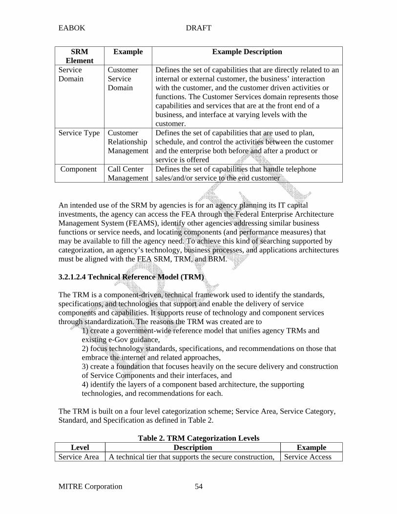
EABOK DRAFT
SRM Example Example Description Element
Service Domain
Customer Service
Defines the set of capabilities that are directly related to an internal or external customer, the business’ interaction
Domain with the customer, and the customer driven activities or functions. The Customer Services domain represents those capabilities and services that are at the front end of a business, and interface at varying levels with the customer.
Service Type Customer Relationship Management
Defines the set of capabilities that are used to plan, schedule, and control the activities between the customer and the enterprise both before and after a product or service is offered
Component Call Center Defines the set of capabilities that handle telephone Management sales/and/or service to the end customer
must be aligned with the FEA SRM, TRM, and BRM.
An intended use of the SRM by agencies is for an agency planning its IT capital investments, the agency can access the FEA through the Federal Enterprise Architecture Management System (FEAMS), identify other agencies addressing similar business functions or service needs, and locating components (and performance measures) that may be available to fill the agency need. To achieve this kind of searching supported by categorization, an agency’s technology, business processes, and applications architectures
3.2.1.2.4 Technical Reference Model (TRM)
The TRM is a component-driven, technical framework used to identify the standards, specifications, and technologies that support and enable the delivery of service components and capabilities. It supports reuse of technology and component services through standardization. The reasons the TRM was created are to
1) create a government-wide reference model that unifies agency TRMs and existing e-Gov guidance, 2) focus technology standards, specifications, and recommendations on those that embrace the internet and related approaches, 3) create a foundation that focuses heavily on the secure delivery and construction of Service Components and their interfaces, and 4) identify the layers of a component based architecture, the supporting technologies, and recommendations for each.
The TRM is built on a four level categorization scheme; Service Area, Service Category, Standard, and Specification as defined in Table 2.
Table 2. TRM Categorization Levels Level Description Example
Service Area Service AccessA technical tier that supports the secure construction,
MITRE Corporation 54

est anagement, ng
EABOK DRAFT
exchange, and delivery of business or service components. Each service area groups the requirements of component-based architectures within the Federal Governement into functional areas.
and Delivery
Service Category
Sub-tier of the Service Area to classify lower levels of technologies, standards, and specifications in respect to the business or technology function they serve
Access Channel
Standard Hardware, software, or specifications that are widely used and accepted (de facto) or are sanctioned by a standards organization (de jure).
Web Browser
Specification A formal layout/blueprint/design of an application development model for developing distributed component-based architectures.
Internet Explorer
Figure 11 shows the four service areas, their service categories (underlined), and their standards. The OMB TRM writeup contains a description of each of these and associated specifications.
Service Access and Delivery Access Channels Web Browser Wireless/PDA Device Collaboration / Communication Other Electronic Channels
Delivery Channels Internet, Intranet Extranet Peer to Peer (P2P) Virtual Private Network (VPN)
Service Requirements Legislative / Compliance Authentication / Single Sign-On Hosting
Service Transport Network Services
Transport
Service Platform and Infrastructure Support Platforms Wireless / Mobile Platform Independent (J2EE) Platform Dependent (.NET)
Database / Storage Database Storage Devices
Delivery Servers Web, Media Application Portal
Software Engineering Integrated Development Environment (IDE) Software Configuration Management (SCM)
Hardware / Infrastructure Servers Computers
Embedded Technology Devices Peripherals WAN/LAN
Network Devides/Standards Video Conferencing
T ing M Modeli Component Framework Security Certificates / Digital Signature Supporting Security Services
Data Interchange Data Exchange
Presentation / Interface Static Display Dynamic Server – Side Display Content Rendering Wireless / Mobile / Voice
Business Logic Platform Independent Platform Dependent
Data Management Database Connectivity Reporting and Analysis
Service Interface and Integration Integration Middleware Database Access Transaction Processing Object Request Broker
Interoperability Data Format / Classification Data Types / Validation Data Transformation
Interface Service Discovery
Service Description / Interfae
Figure 11. TRM Version 1.0 Service Areas, Service Categories, and Standards
OMB views the TRM as providing “the foundation for identifying target technical architectures and should be reflected where applicable in baseline architectures. Migration strategies should be developed to outline the approach to achieving the target
MITRE Corporation 55
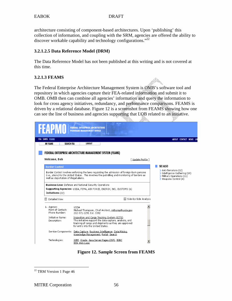
EABOK DRAFT
architecture consisting of component-based architectures. Upon ‘publishing’ this collection of information, and coupling with the SRM, agencies are offered the ability to discover workable capability and technology configurations.”22
3.2.1.2.5 Data Reference Model (DRM)
The Data Reference Model has not been published at this writing and is not covered at this time.
3.2.1.3 FEAMS
The Federal Enterprise Architecture Management System is OMB’s software tool and repository in which agencies capture their FEA-related information and submit it to OMB. OMB then can combine all agencies’ information and query the information to look for cross agency initiatives, redundancy, and performance comparisons. FEAMS is driven by a relational database. Figure 12 is a screenshot from FEAMS showing how one can see the line of business and agencies supporting that LOB related to an initiative.
Figure 12. Sample Screen from FEAMS
22 TRM Version 1 Page 46
MITRE Corporation 56

EABOK DRAFT
References
The FEA Program Management Office (PMO) published the OMB Reference Models. Official version of the Reference Model descriptions can be found on the FEAPMO Web site. http://www.feapmo.gov
The Business Reference Model Version 2.0, FEA-PMO, June 2003. The Business Reference Model Version 1.0, FEA-PMO, July 2002.
2003. The Technical Reference Model Version 1.0, FEA-PMO, June 2003.
Patterns for e-business, A Strategy for Reuse
Architecture 2003, September 10, 2003.
(NCOW RM) - Future
References
Performance Reference Model Development, FEA-PMO, October 29, 2002 The Performance Reference Model Version 1.0, FEA-PMO, DRAFT, July 2003 The Service Component Reference Model (SRM) Version 1.0, FEA-PMO, June
, Jonathan Adams, Srinivas Koushik, Guru Vasudeva, and George Galambos, Double Oak, TX:IBM Press, 2001
How FEA Reference Models Impact Agency-Wide Strategies, Diane A. Reeves, OMB, Scott Bernard, Syracuse University, August 20, 2003 presented at e-gov Enterprise
http://www.e-gov.com/events/2003/ea/downloads/
3.2.2 Net-Centric Operations and Warfare (NCOW) Reference Model
This section will discuss DoD’s NCOW RM.
3.2.3 The Global Information Grid (GIG) – Future
This section will discuss the GIG.
Habitats: Organizing the Global Information Grid, Assad Moini, Software Productivity Consortium, http://www.software.org/pub/darpa/habitats/overview.pdf
MITRE Corporation 57
EABOK DRAFT
3.3 Processes for Developing the EA23
Dr. Paula Hagan MITRE Corporation, Software Engineering Center
703 883 6518 [email protected]
Deskbook.
3.3.1 Introduction
There have been several publications on how to gather the information for an Enterprise Architecture (EA), each with different scopes and detail. The scopes vary with such things as whether they address getting executive support, maintenance of the EA, and using the EA. They all address the process of building EA products. At least three of them are based on a particular architecture framework. The concepts and tasks within all of them are generally applicable and the planner can gain insight from examining each of them. None of them are complete because they do not deal with all topics, such as planning, selecting tools, or estimating cost.
The following sections provide overviews of the DoD Architecture Framework (DODAF) six step process which is a high-level, simple introduction, Enterprise Architecture Planning (EAP) which was developed by Steven Spewak and based on the Zachman EA Framework, the process presented in the Practical Guide to the Federal Enterprise Architecture which is based on the Federal Enterprise Architecture Framework (FEAF), and The Open Group Architecture Framework (TOGAF) Architecture Development Method (ADM) . The sections also identify other sources of information. A Work Breakdown Structure (WBS) for EA development can be found in the DODAF
3.3.2 DODAF Six Step Process
The DODAF has a high-level, generic six step process for building an EA shown in Figure 1 and described in Volume Three (Deskbook), Section 2.4, of the DODAF. The description has detail on developing the DODAF operational, systems, and technical views and a suggested build sequence for DODAF products. The DODAF Deskbook Section 2.5 contains Department of the Navy CIO process guidance that includes a work breakdown structure for developing DODAF architecture products and identifies a web site that contains the full navy Architecture Development Process Model (ADPM).
23 Revised January 19, 2004
MITRE Corporation 58

EABOK DRAFT
/
Ti
iistics
detail across the
l
product set)
built
Use
l
i
1
2 3 4 5 6
Figure 1. DODAF Six-Step Process for EA Development
Geographicaloperational bounds
mephase(s) Functional bounds Technology constraints Architecture resources/ schedule
Requ red character(commensurate
different views) and measures of performance
All essentiaproducts Relevant supporting products
Completed architecture (populated
Prudent investments Improved business processes Increased interoperability
Determine the architecture
scope
Determine the Characteristics To be captured
Determine the Views and
Products to be
Determine the requisite products
architecture for intended
purpose
Purpose Critica issues
Target objectives Key tradeoffs
Probably analys s methods
Universal Guidance
Determine the Intended use of
architecture
3.3.3 MetaGroup Process Model
The MetaGroup developed a process model that has a broader focus including the need for the business vision, the cycle of applying and revising the architecture, and assessing the EA program. A modified version of it is shown in Figure 2.
MITRE Corporation 59
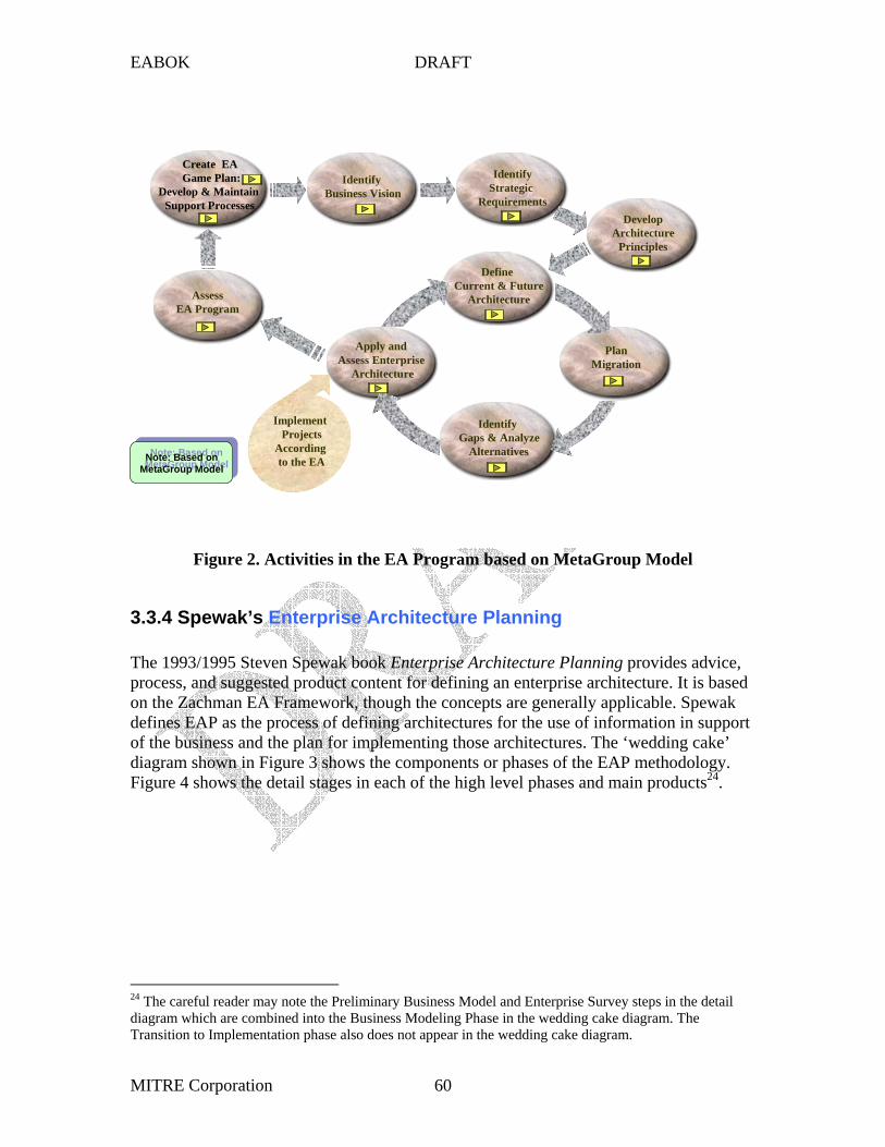
EABOK DRAFT
EA l
to the EA
The 1993/1995 Steven Spewak book provides advice,
24 .
CreateGame P an:
Develop & Maintain Support Processes
Identify Business Vision
Identify Strategic
Requirements Develop
Architecture Principles
Assess EA Program
Apply and Assess Enterprise
Architecture
Define Current & Future
Architecture
Plan Migration
Identify Gaps & Analyze
Alternatives
Implement Projects
According Note: Based on MetaGroup Model Note: Based on
MetaGroup Model
Figure 2. Activities in the EA Program based on MetaGroup Model
3.3.4 Spewak’s Enterprise Architecture Planning
Enterprise Architecture Planning process, and suggested product content for defining an enterprise architecture. It is based on the Zachman EA Framework, though the concepts are generally applicable. Spewak defines EAP as the process of defining architectures for the use of information in support of the business and the plan for implementing those architectures. The ‘wedding cake’ diagram shown in Figure 3 shows the components or phases of the EAP methodology. Figure 4 shows the detail stages in each of the high level phases and main products
24 The careful reader may note the Preliminary Business Model and Enterprise Survey steps in the detail diagram which are combined into the Business Modeling Phase in the wedding cake diagram. The Transition to Implementation phase also does not appear in the wedding cake diagram.
MITRE Corporation 60
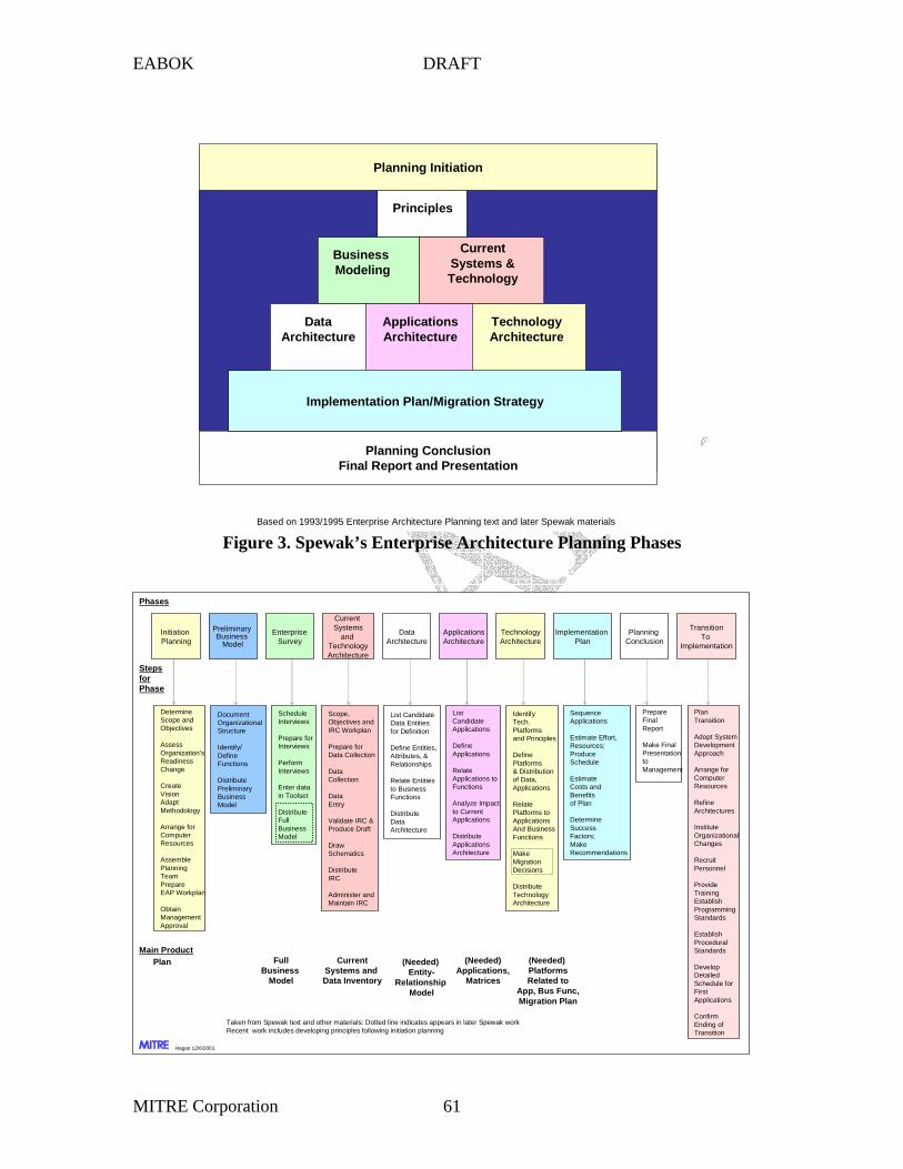
EABOK DRAFT
i i l l ials
iPl
Adapt
le
l
i
lan
ll i
Coll i
li
i
Di i
inii
Dataand l
i l
Identi / i
ions
Di ii
l
iImpl Pl
l ion
itiTo
iti
i ii
ies to Busi
ions
Di i
i
i
ii
Reliions
i
Di iii
i
of Plan
i
l
i l
to
Refii
l
it
iing
ing
l
lop il
i
ii
l i ll i l i
( ( ) ( )
MITRE
le
l
iFull
l
Identi
iples
ine
i i
i
Rel
ii
ions
Mi
Di i
i
Planning Initiation
Planning Conclusion Final Report and Presentation
Implementation Plan/Migration Strategy
Technology Architecture
Principles
Business Modeling
Current Systems & Technology
Data Architecture
Applications Architecture
Based on 1993/1995 Enterpr se Arch tecture P anning text and ater Spewak mater
Figure 3. Spewak’s Enterprise Architecture Planning Phases
Initiat on anning
Determine Scope and Objectives
Assess Organization’s Readiness Change
Create Vision
Methodology
Arrange for Computer Resources
AssembPlanning Team Prepare EAP Workplan
Obtain Management Approva
Enterprise Survey
Appl cations Architecture
Scope, Objectives and IRC Workp
Prepare for Data Co ect on
Data ect on
Data Entry
Va date IRC & Produce Draft
Draw Schemat cs
str bute IRC
Adm ster and Mainta n IRC
Architecture
Current Systems
Technology Architecture
Preliminary Business
Mode
Document Organ zationaStructure
fyDef ne Funct
str bute Prelim nary Business Mode
Technology Arch tecture
Phases
ementation Plan
anning Conc us
Trans on
Implementation
List Candidate Data Entities for Defin on
Def ne Entit es, Attr butes, & Relationships
Relate Entitness
Funct
str bute Data Arch tecture
List Candidate Appl cations
Def ne Appl cations
ate Appl cations to Funct
Analyze Impact to Current Appl cations
str bute Appl cations Arch tecture
Sequence Appl cations
Estimate Effort, Resources; Produce Schedule
Estimate Costs and Benefits
Determ ne Success Factors; Make Recommendations
Prepare FinaReport
Make F naPresentation
Management
Plan Transition
Adopt System Development Approach
Arrange for Computer Resources
ne Arch tectures
Institute OrganizationaChanges
RecruPersonnel
Prov de TrainEstablish ProgrammStandards
Establish ProceduraStandards
DeveDeta ed Schedule for First Appl cations
Conf rm Ending of Transition
Hagan 12/6/2001
Taken from Spewak text and other mater als: Dotted line indicates appears in later Spewak work Recent work includes deve op ng principles fo owing nitiation p ann ng
Plan Full Business
Model
Current Systems and Data Inventory
Needed) Entity-
Relationship Model
NeededApplications,
Matrices
NeededPlatforms Related to
App, Bus Func, Migration Plan
Main Product
Steps for Phase
ScheduInterviews
Prepare for Interviews
Perform Interviews
Enter data in Too set
Distr bute
Business Mode
fy Tech. Platforms and Princ
DefPlatforms & D str bution of Data, Appl cations
ate Platforms to Appl cations And Bus ness Funct
Make gration
Decisions
str bute Technology Arch tecture
MITRE Corporation 61

EABOK DRAFT
Figure 4. EAP Process Steps for Each Phase
Spewak’s EAP was foundational work at the time it was written. It champions the 80/20 rule - showing results quickly rather than getting the last detail correct. The text contains many checklists, ideas for planning, example products, and practical advice. Spewak does not favor a fixed set of EA products, but rather would determine the specifics of EA products on a case by case basis25. He emphasizes the use of matrices to relate elements of the EA, e.g., systems to business functions.
3.3.5 Practical Guide Process
in i
i
ii
Poli
ior i
i i
lil
Reviittee
liCapi l
il )
lii
ittee
i
li
ice
i
l
( i il i
l
i-l
l
il
ii
i i
i
ii
i
i
Seli
Sel
Sel
ii
i
i
i
i)
lder i
i
ili ia
i
i i
lii
litori
lop li
ii
lop Target
ii
li
liTarget
Di
i
i
Train l
li
i
Cri
/
Mili
in
i
EA i lly
ider
EA i
l
ify
i
i
A Practical Guide to the Federal Enterprise Architecture provides a process for developing an EA as shown in Figure 5. The process steps overlap with those in the Spewak EAP processes. The Practical Guide adds governance, more on tools, establishing a Program Mangement Office (PMO), transitioning, and marketing the EA. The practitioner can combine Practical Guide and EAP process ideas.
ObtaExecut ve Buy-in and Support
CIO Ensure Agency Head Buy- n and Support
Issue Executive Enterpr se Arch tecture
cy
Obtain Support From SenExecut ves and Bus ness Un ts
Estab sh Technica
ew Comm
Estab sh ta
Investment Counc (CIC
Estab sh EA Execut ve Steering Comm
Appoint Chief Arch tect
Estab sh EA Program Management Off
Establ sh Management and Structure
Contro
EA Program Activities
and Products)
Def ne an Architecture Process and
Approach
Use the Enterprise
Architecture
Ma ntain the Enterprise Architecture
Deve op the Enterprise Arch tecture Control and Oversee EA
Program
Deve op EA Marketing Strategy and Communcations P an
Deve op EA Program Management Plan
Init ate Deve opment of Enterpr se Arch tecture
Def ne ntended Use of Arch tecture
Def ne Scope of Arch tecture
Determ ne Depth of Arch tecture
ect Appropr ate EA Products
Evaluate and ect a
Framework
ect an EA Toolset
Rev ew Documentat on And Literature
Conduct Prelim nary Meetings and Interv ews
Conduct Familiarizat on Training
Generate Prelim nary (StrawmanProducts
Conduct StakehoBrainstorm ng
Conduct SME – In-Depth Interv ews
Revise Products As Needed
Rev ew and Va date vIndependent & SME rev ew
Generate and Present Br ef ng
Get TRC, EAESC Approval
Pub sh Arch teture Products
Popu ate Tools & Repos es
DeveBase ne Enterpr se Arch tecture
Deve
Enterpr se Arch tecture
Deve op the Sequenc ng Plan
Identify Gaps-Base ne and
Define and fferentiate
Legacy, Migrat on, and New Systems
Plan the Migrat on
Integrate EA, CPIC, & SLC Processes
Personne
Estab sh Enforcement Processes and Procedures
Def ne Compliance
teria and Consequences
Set Up Integrated CPIC EA Enforcement
estone Rev ews
Execute the Integrated Process
MaintaEA As Enterpr se Evolves
Reassess
Period ca
ConsProposals for
Mod fications
Ensure PM Controls in P ace, Functioning
IdentWhere EA Program Expectations Not Met
Take Action to Address Dev ations
Ensure Cont nuous Improvement
Figure 5. Process Steps from the Practical Guide
25 Based on statement by Spewak at FEAF revision Committee meeting.
MITRE Corporation 62
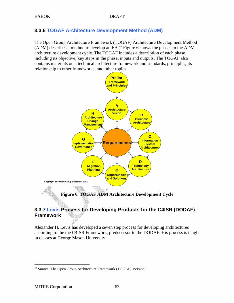
EABOK DRAFT
3.3.6 TOGAF Architecture Development Method (ADM)
The Open Group Architecture Framework (TOGAF) Architecture Development Method (ADM) describes a method to develop an EA.26 Figure 6 shows the phases in the ADM architecture development cycle. The TOGAF includes a description of each phase including its objective, key steps in the phase, inputs and outputs. The TOGAF also contains materials on a technical architecture framework and standards, principles, its
A
H
G
D
C
B
E
F
Prelim:
3.3.7
relationship to other frameworks, and other topics.
Architecture Vision
Architecture Change
Management
Implementation Governance
Technology Architecture
Information System
Architectures Requirements
Business Architecture
Opportunities and Solutions
Migration Planning
Framework and Principles
Copyright The Open Group December 2002
Figure 6. TOGAF ADM Architecture Development Cycle
Levis Process for Developing Products for the C4ISR (DODAF) Framework
Alexander H. Levis has developed a seven step process for developing architectures according to the the C4ISR Framework, predecessor to the DODAF. His process is taught in classes at George Mason University.
26 Source: The Open Group Architecture Framework (TOGAF) Version 8.
MITRE Corporation 63
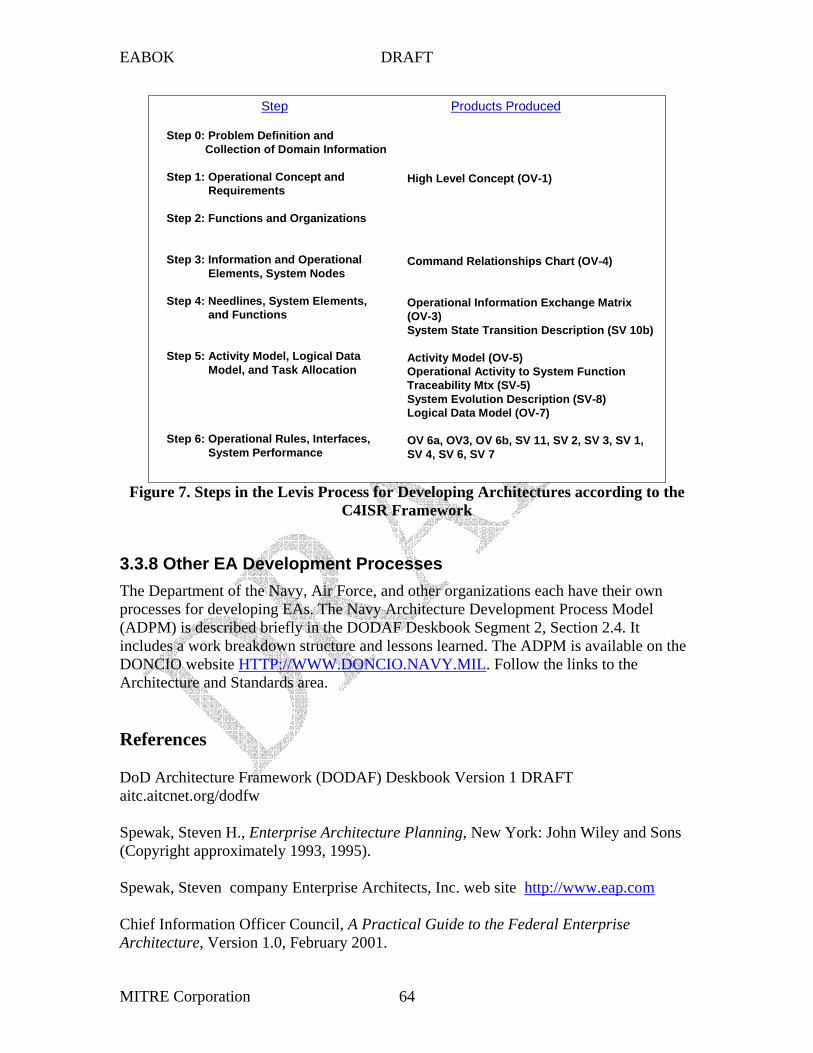
EABOK DRAFT
(OV-3)
(SV-5)
DONCIO website HTTP://Architecture and Standards area.
Step 0: Problem Definition and Collection of Domain Information
Step 1: Operational Concept and Requirements
Step 2: Functions and Organizations
Step 3: Information and Operational Elements, System Nodes
Step 4: Needlines, System Elements, and Functions
Step 5: Activity Model, Logical Data Model, and Task Allocation
Step 6: Operational Rules, Interfaces, System Performance
High Level Concept (OV-1)
Command Relationships Chart (OV-4)
Operational Information Exchange Matrix
System State Transition Description (SV 10b)
Activity Model (OV-5) Operational Activity to System Function Traceability Mtx System Evolution Description (SV-8) Logical Data Model (OV-7)
OV 6a, OV3, OV 6b, SV 11, SV 2, SV 3, SV 1, SV 4, SV 6, SV 7
Step Products Produced
Figure 7. Steps in the Levis Process for Developing Architectures according to the C4ISR Framework
3.3.8 Other EA Development Processes The Department of the Navy, Air Force, and other organizations each have their own processes for developing EAs. The Navy Architecture Development Process Model (ADPM) is described briefly in the DODAF Deskbook Segment 2, Section 2.4. It includes a work breakdown structure and lessons learned. The ADPM is available on the
WWW.DONCIO.NAVY.MIL. Follow the links to the
References
DoD Architecture Framework (DODAF) Deskbook Version 1 DRAFT aitc.aitcnet.org/dodfw
Spewak, Steven H., Enterprise Architecture Planning, New York: John Wiley and Sons (Copyright approximately 1993, 1995).
Spewak, Steven company Enterprise Architects, Inc. web site http://www.eap.com
Chief Information Officer Council, A Practical Guide to the Federal Enterprise Architecture, Version 1.0, February 2001.
MITRE Corporation 64

EABOK DRAFT
Bienvenu, M., I. Shin, and A. Levis, C4ISR Architectures III: An Object-Oriented Approach for Architecture Design, Systems Engineering, Vol. 3, No. 4, Fall 2000.
The Open Group Architecture Framework (TOGAF) Version 8 Enterprise Edition. http://www.opengroup.org/architecture/
Levis, A., and L. Wagenhals, C4ISR Architectures I: Developing a Process for C4ISR Architecture Design, To be published, Systems Engineering, Vol. 3, No. 4, Fall 2000.
, to be publishedEngineering, Vol. 3, No. 4.
Navy ADPM process description
Wagenhals, L., I. Shin, D. Kim, & A. Levis, C4ISR Architectures II: A Structured Analysis Approach for Architecture Design, Fall 2000 , Systems
http://www.doncio.navy.mil
MITRE Corporation 65

EABOK DRAFT
3.4 Modeling Methods27
Fatma Dandashi MITRE Corporation, Software Engineering Center
703 883 7914 [email protected]
Paula Hagan
703 883 6518
Table of Contents 3.4.1. Introduction 3.4.2 The Business Process Model
3.4.2.1 Purpose 3.4.2.2 Model Content 3.4.2.3 Modeling Techniques
3.4.2.3.2 BPMN
3.4.2.3.4 IDEF 0 3.4.2.4 3.4.2.5 Related Disciplines
3.4.2.5.1 Business Process Engineering - FUTURE
3.4.3 The Data Model - FUTURE
redundant efforts.
MITRE Corporation, Software Engineering Center
3.4.2.3.1 A Simple Hierarchy Chart
3.4.2.3.3 UML Diagrams
Organizing the Business Processes – Value Chain Management Analysis
3.4.2.5.2 Activity Based Costing - FUTURE
3.4.1 Introduction Economy demands that all elements of an enterprise fit together and work well
with minimal investment while taking advantage of reuse and eliminating unnecessary Elements of an enterprise include the business processes,
organizations responsible for them, information and systems data they need to inter-operate, information technology (IT) capabilities, systems, infrastructure, and specific technical standards that facilitate their inter-operation. An enterprise architecture (EA) describes these elements, their structures, and inter-relationships to facilitate capital planning and IT development sequencing.
EA models allow understanding and visualization of enterprise elements and their relationships, and facilitate analysis. The modeling done for Enterprise Architecture includes many aspects of the enterprise such as business processes, resources (people as
27 Revised October 2003
MITRE Corporation 66

Software Engineering
SoftwareArchitecture
System of Systems (Enterprise)Engineering
EnterpriseArchitecture
Systems Engineering
System Architecture
Structured Analysis & Design• IDEF0• Data Flow• ER Diagrams
OO Analysis & Design• Use Case Diagrams• Activity Diagrams• Class Diagrams
Structured Analysis & Design• IDEF0• Data Flow• ER Diagrams
OO Analysis & Design• Use Case Diagrams• Activity Diagrams• Class Diagrams
• Network Diagrams
• Hardware Layout Diagrams
• Models & Simulation
Structured Analysis & Design• IDEF0• Data Flow• ER Diagrams
OO Analysis & Design• Use Case Diagrams• Activity Diagrams• Class Diagrams
• Organizational Diagrams
• Enterprise Vision
Functions (How)
Data (what)
Network (where)
Time (When)
People (Who)
Motivation (Why)
Network
Time• Network Diagrams
• Hardware Layout Diagrams
• Models & Simulation
Functions
Data
Functions
Data
EABOK DRAFT
well as IT and other equipment), systems, infrastructure, and so on. By way of comparison, software design models are used in software and systems analysis. Similarly, EA models addresses enterprise elements at different levels of detail and have a broader scope. Figure 1 shows some of the differences in elements modeled and modeling techniques used in software, system, and enterprise models.
business and data of an enterprise.
)
ArchitectureArchitecture
•
•
•
)
)
)
Network
Time •
•
•
Figure 1. Differences in Elements Modeled and Modeling Approaches
The following sections identify some modeling issues and techniques for modeling the
3.4.2 The Business Process Model
The sophistication of the enterprise architecture business model has ranged from the simple activity hierarchy chart to extensive business process, software, and information flow modeling notations (e.g., BPMN [BPMI, 2002], IDEF0 [FIPS 183 1993], and UML [OMG, 2002]). The practitioner must determine the reason(s) for modeling the processes, the elements related to processes wanted, the organization strategy for the processes, the
Software Engineering
Software Architecture
System of Systems (EnterpriseEngineering
Enterprise
Systems Engineering
System
Structured Analysis & Design • IDEF0 • Data Flow • ER Diagrams
OO Analysis & Design • Use Case Diagrams • Activity Diagrams • Class Diagrams
Structured Analysis & Design • IDEF0 • Data Flow • ER Diagrams
OO Analysis & Design • Use Case Diagrams • Activity Diagrams • Class Diagrams
Network Diagrams
Hardware Layout Diagrams
Models & Simulation
Structured Analysis & Design • IDEF0 • Data Flow • ER Diagrams
OO Analysis & Design • Use Case Diagrams • Activity Diagrams • Class Diagrams
• Organizational Diagrams
• Enterprise Vision
Functions (How
Data (what)
Network (where)
Time (When
People (Who)
Motivation (Why
Network Diagrams
Hardware Layout Diagrams
Models & Simulation
Functions
Data
Functions
Data
process modeling technique, and the level of detail needed to begin the modeling process.
3.4.2.1 Purpose of the Business Process Model There are many reasons to create a business model, for example:
1. Get a first round general picture of how the enterprise operates 2. Identify the current authority and accountability for the process 3. Show the relationship other elements like IT, data, etc. 4. Provide a communications tool 5. Provide a basis for cost modeling
MITRE Corporation 67

EABOK DRAFT
6. Provide a basis for simulation 7. Provide a basis for performance assessments 8. Provide a basis for process reengineering 9. Define new methods or processes 10. Provide a basis for systems development 11. Show the future or expected manner of operation 12. Show alignment with other business processes in other organizations
The reasons for developing a business process model affect the information to be shown,
purposes as well. is an abstraction that yields a
[RM-ODP 1996].
activities.
Activities
Processes Resources People
Sequencing Dependencies
the level of detail needed, the type of model, process breakdown or categories, and the relationships shown to other aspects of an enterprise such as its data, organizations, and information systems. For example, the categories of business processes used for cost analysis may be more closely related to budget line items whereas business processes for IT design may be more closely related to decomposition for communications or system boundary separation. No matter what reason for developing the business model is chosen, as a resource describing the business, the model will in all likelihood be adapted for other
Models also typically have viewpoints. A viewpoint specification of the whole enterprise related to a particular set of concerns (adapted from
Business models could be presented as the executive sees the company, the service provider, the customer, IT needs, accounting, etc. The viewpoint affects what information is modeled, what detail is captured, and sometimes the style of presentation. The Zachman EA Framework represents the views of five users of the EA - the planner, owner, designer, builder, and subcontractor in each of the five rows, each with different associated models and different information in the models. Other possible viewpoints might be that of the Citizen or that of a particular Government Agency.
3.4.2.2. Business Process Model Content It may seem obvious that the business model is going to model the business activities, but some models model capabilities, some high level functions, some processes, some
The following list suggests the variety than can be included depending on the intended uses of the model.
Capabilities High-level Functions
Time required Relative timing
Coordination requirements Collaboration
Organizations Locations Data used or generated (inputs and outputs) It Systems Equipment Costs Roles
Constraints Controls Parallelism possible Decision points Business rules Automated or manual activities Transaction vs. processes distinction
MITRE Corporation 68

EABOK Draft
3.4.2.3 Process Modeling Techniques This section discusses various popular techniques for business process modeling
and does not include a discussion of other modeling techniques (such as modeling the dynamic behavior of a software system). Styles of modeling business processes have come out of the business process reengineering, cost modeling, and system/software engineering arenas. Table 1 shows some methods and the type of information they portray. The following sections discuss some of the techniques and point the reader to fuller discussions of them. The discussion will address only styles of diagrams (methodologies) to show what the style has to offer to allow the reader to determine whether he may want to explore it further.
Table 1. Information portrayed by Modeling Techniques Category Examples Reference Information Depicted User requirements and business tasks
BPMN UML Use Case Diagrams
[BPMI, 2002] [OMG, 2001]
Business process flow The use cases represent functionality of a system or a classifier, like a subsystem or a class, as manifested to external actors with the system or the classifier.
Task Dependency
PERT Chart Gannt Chart
Activity breakdown Required sequences
Flow Chart Schedule (for Gantt charts) Decision Point Diagram UML Activity Diagram
[OMG, 2001]
Components, decisions (for Flow Charts) Complex Decisions (for Decision Point Diagram)
Information Flow
BPMN Data Flow Diagram (DFDs) IDEF0 Diagram
BPMI, 2002 [DeMarco 1979], [GANE 1977], [Yourdon 1989] [FIPS 183 1993]
Information Flow Activity breakdown Activity inputs, outputs Mechanisms, controls (for IDEF0)
UML Sequence Diagram
[OMG, 2001]
Work Flow IDEF3 Model [IDEF3, 1995] Activity breakdown, Role assignments
BPMN [BPMI, 2002] Modeling of complex business processes with consideration for implementation, architecture, and technology in environments such as Web Services.
Dynamic UML Sequence [OMG, 2001] Sequence and timing of Behavior Diagram operations, events, and Event-Trace information flow Diagram Dynamic Petri-Nets, [Kristensen, 1998] the states which the system may Behavior Harel Statecharts [HAREL 1987a,b] be in and the transitions between State UML State [OMG, 2001] these states Transition Transition Diagrams Diagram
3.4.2.3.1 A Simple Function Hierarchy Chart
MITRE Corporation 69

EABOK Draft
The function hierarchy chart, sometimes called a node tree diagram, lists the high level functions of the business in a hierarchical decomposition (See Figure 2). It usually goes to three or four levels of detail. The diagram is usually presented in one of two forms. One uses a columnar arrangement of the activities as shown below. The other has a more inverted tree branches-like appearance. The choice of which style to use is the modeler’s and will depend on the number of boxes – breadth and depth of the hierarchy - to be presented and the customary practice of the modeling group. The chart provides no detail on, for example, IT systems used, locations, or organizations. The chart does confront the issues of what are the business functions, and how to organize and separate functions.
i
i l i l f
l i i
ii
ii ii i
j i i
i ifi
ii
i
i i i i
il i il i
ii
l i i i
i
if i i
f i
i lii
ii i
i l ii
i
i i i le i l i i
i
li
lii mi I
lii l l l i
i l l l i
Depending on the skill of the modeler, they may give some sense of process flow or business organization structure. Hierarchical function charts provide a quick context reference with no distraction by other information. They can be useful even if a more sophisticated model is available.
FEDERAL INT ERNATIONAL TRADE PILOT ARCHITECTURE ACTIVITY HIERARCHY CHART
A0 Perform Federal International Trade Respons bilities
A6 Man ag e Trade Infrastr ucture A2 Manage Internat ona Trade Trans act ons
A1 Promote Ex port Trad e
A4 Com pil e an d Ana yze Tra de In orm atio n
A5 Dev elo p Po cy an d Ne got ate Trade Agr eem ents
A61 License Sure ty Compan es A62 Manage Brokers’ Licenses and Per m ts A63 License, Inspect, and Superv se Warehouses A64 Adm nister Fore gn Trade Zones A65 Prov de Transportaton In frastructure A66 Process Protests and Ad ud cate D sputes
A21 Manage Import Transactions A211 Manage Import Licenses,Per m ts, and Cer t ca tes
of Compliance A212 Process Author zed Bonds A213 Process Entry Doc umenta ton
A2131 Ver fy Bond has Been Posted A2132 Examine Visa and Quota Restric tions and Documents A2133 Ver fy Licenses and Perm ts A2134 Deter mine Intens ve Inspection Cand dates
A214 Conduct Import Border-Only Operatons A2141 Pace Goods n Fore gn Trade Zone A2142 Pace Goods n Bonded Warehouse A2143 Conduct Inspections
A215 Process Tar ff And Fee Payments A2151 Process Entry Sum mar es A2152 Process Payment Monies A2153 Reconci e and L iqu date Transacton En tr es
A22 Manage Export Transactons A221 Manage Export Licenses A222 Provide Cert catons A223 Process SED A224 Per orm R s k Assessment A225 Conduct Necessary Export Examinat ions A226 Process Drawback Payments
A11 Prov de Pub c Walk-In ,Call- In, Web, and Classroom Trade In format on
A12 Encourage U.S. Compan es to Export A13 Prov de Foreign Market Informa ton A14 Promote US Goods Abroad A15 Assis tCompany w th Its ExportDea
A151 Prov de Leads and Contac ts A152 Prov de Tailored Marketor Company
Reports or Sta tis tics A153 Prov de Loan Guarantees , Loan Insurance,
or Loans A154 Increase Market Access A155 Advocate for Company a t Proposal Evaluat ion
A41 Prov de Harmon zed Tar ff ScheduA42 Comp e Import and Export Sta ts tcs A43 Evaluate Trends, Impacts, and Trade Practces
A51 Develop Trade Po icy A52 Negota te Trade Agree ments A53 Pursue Trade Agree ment En forcement
15 Au g 200 1
A3 Co nduct C omp a nce and Cr n al nve stigat ions
A31 Inspect In formed Comp ance Procedures A32 Preventand Investgate I ega Import Sh pments
and Fraud A33 Preventand Investgate I ega Export Sh pmen ts
Figure 2 Example of a Hierarchy Function Chart
3.4.2.3.2 Business Process Management Notation Editor’s Comment: This topic will be addressed more thoroughly in a future edition. Business Process Management Notation (BPMN) is a standard notation for business process modeling that is the result of the Business Process Management Initiative. The initiative (BPMI.org) is a non-profit corporation whose mission is to promote and develop the use of Business Process Management (BPM) through the establishment of standards for process design, deployment, execution, maintenance, and optimization. BPMI.org develops open specifications, assists IT vendors for marketing their
MITRE Corporation 70

EABOK Draft
implementations, and supports businesses for using Business Process Management technologies.
BPMN will provide businesses with the capability of defining and understanding their internal and external business procedures through a Business Process Diagram, which will give organizations the ability to communicate these procedures in a standard manner. BPMN will also be supported with an internal model that will enable the generation of executable BPML.
the Business Process
the-shelf Database
3.4.2.3.3 UML Diagrams
j
BPMN provides a standardized notation for defining internal and external business processes and a formal mechanism to generate an executable business process (such as
Modeling Language [BPML]) from the Business Level notation. BPML is a meta-language for the modeling of business processes, just as XML is a metalanguage for the modeling of business data. BPML provides an abstracted execution model for collaborative & transactional business processes based on the concept of a transactional finite-state machine.
In much the same way XML documents are usually described in a specific XML Schema layered on top of the eXtensible Markup Language, BPML processes can be described in a specific business process modeling language layered on top of the extensible BPML XML Schema. BPML represents business processes as the interleaving of control flow, data flow, and event flow, while adding orthogonal design capabilities for business rules, security roles, and transaction contexts.
BPMI.org also defines open specifications, such as the Business Process Query Language (BPQL), that will enable the standards-based management of e-Business processes with forthcoming Business Process Management Systems (BPMS), in much the same way SQL enabled the standards-based management of business data with off-
Management Systems (DBMSs). The first draft of BPML was made available to the public on March 8, 2001.
The Unified Modeling Language (UML) is a modeling language devoid of a methodology or a modeling process. The UML is maintained as a standard by the Object Management Group [OMG, 2002] which is composed of a broad consortium of ma or companies. The UML contributes several styles of diagrams that are useful for modeling business processes. A diagram is a view into a model, presented from the aspect of a particular stakeholder. It provides a partial representation of the system (or enterprise), and it is semantically consistent with other views. A diagram is a graphical representation of a set of elements, most often rendered as a connected graph of vertices (things) and arcs (relationships). UML diagrams include:
• Class diagram • Object diagram • Behavior diagrams:
o Use Case Diagram
MITRE Corporation 71

EABOK Draft
o Statechart diagram o Activity diagram o Interaction diagrams:
� Sequence diagram � Collaboration diagram
• Implementation diagrams: o Component diagram o
Figure 3. Example Use Case Diagram
( i )
( i ) i
( i
( i )
Deployment diagram
The underlying UML integrates these different perspectives so that a consistent and integrated system can be analyzed and built.
The use case describes the behavior of a system or other semantic entity, like an enterprise, without revealing the entities internal structure. More formally a Use Case is “A specification of sequences of actions including variant sequences and error sequences, that a system, subsystem or class can perform by interacting with outside actors.” Use case diagrams show actors and use cases together with their relationships Use cases are sometimes expressed as narratives. Figure 3 shows an example of a Use Case Diagram.
DeactivateSystem from Bus ness Use-Case Model
ActivateAll from Bus ness Use-Case Model
Secur tyGuard from Bus ness Use-Case Model)
ActivateFireOnly from Bus ness Use-Case Model
TriggerSensor Burglar (from Business Use-Case Model)
Fire (from Business Use-Case Model)
(from Business Use-Case Model)
MITRE Corporation 72

EABOK Draft
Use Case Interaction Diagrams consist of sequence diagrams or collaboration diagrams (equivalent). They show:
– Roles (classes) or their instantiated objects – Association roles Or links (in case of instantiated diagrams) – Messages and message flow
Sequence diagrams describe the time-ordered sequence of messages sent between instances. The sequence diagram is also called an event trace or event flow diagram in some methodologies. Sequence diagrams show the sequence of events that occurs between sending and receiving participants – objects, usually for a scenario describing a
Figure 4. Example of a Sequence Diagram
– • Use cases • Classes • •
cases) Nodes (a collection of components/software and other
: i : l
: i
l
() ()
i () i
Tri
I
(i l )
business process or transaction. Event trace diagrams are good for capturing the sequence of actions. Figure 4 shows an example of a sequence diagram.
Activity diagrams model a process as a collection of activities and transitions between those activities, i.e., they model the dynamic behavior of the business processes.
Typically attached to (to capture the behavior of):
Interfaces Components (a collection of classes that realize a use case or use
SecurityGuard : Burglar : S ren
Contro Box Secur tySensorMonitor : FireSensorMonitor : SecuritySensor Hal : SecuritySensor
Activate
Sound(pip)
Monitor
Tr ggerTr gger
gger
ntruder
Sound ntruderAert
Monitor
• components/hardware)
• Operations (within classes and objects)
MITRE Corporation 73

Design NewProduct
Sell Product
MarketProduct Manufacture
Product
DeliverProduct
Marketing DeliveryManufacturing
DesignReady
Design Not Ready
EABOK Draft
models.
3.4.2.3.4 IDEF0 Diagrams
Forks
Joins
ReadyReady
Figure 5. Example of a UML Activity Diagram
The DoDAF provides suggestions on using UML with the DODAF products. The examples are useful to consider using UML with any framework’s business process
‘IDEF function modeling is designed to represent the decisions, actions, and activities of an existing or prospective organization or system. IDEF0 graphics and accompanying text are presented in an organized and systematic way to gain understanding, support analysis, provide logic for potential changes, specify requirements, and support system-level design and integration activities. (from IDEF 0 standard document)‘ IDEF0 is used heavily in military and industrial environments. The references cite the standard for IDEF0 Modeling. IDEF0 has a top level context diagram, decomposition diagrams, and
Swimlanes
Design New Product
Sell Product
Market Product Manufacture
Product
Deliver Product
Marketing Delivery Manufacturing
Design Design Not
facing page text that describes the diagrams.
The Context Diagram establishes the bounds for the model and depicts the major Inputs, Controls, Outputs, and Mechanisms (ICOMS) used to perform the activity as shown in Figure 6. The diagram consists of a single box and its related ICOMS. It sets the general context and scope of what is being modeled and displays the purpose and viewpoint of the model. This diagram is labeled A-0 (A minus 0).
MITRE Corporation 74

EABOK Draft
(
Figure 6. IDEF0 Context Diagram Style
Activity
Activity Controls Data that constrains or regulates the activity. Controls regulate the transformation of inputs to outputs
Activity Outputs Data or materials produced by or resulting from the activity
Activity Inputs Data or material used to produce an output of an activity
Activity Mechanisms Resources usually people, machines, or systems) that provide energy to or perform the activity
Context Diagram
Purpose: State the purpose of the model here
Viewpoint: Give the viewpoint of the model here
The Decomposition Diagram describes the components of an activity and their relationships to one another (See Figure 7). The diagrams also show the flow of ICOMs among activities. A decomposition diagram shows only one level of decomposition below its parent on each page. The first decomposition diagram of a model is labeled A0. The subsequent second level decomposition diagrams are labeled with the number of the box within A0 that they refine, e.g., A1 or A3. Third level decomposition labels could be, for example, A11 for a box that refines A1 or A32 for a box that refines A3. There is no significance to the size of boxes. Some are larger to accommodate spacing ICOMs neatly. By tradition the boxes are arranged upper left to lower right within a page. The order of boxes on the page does not imply a sequence of operations. Figure 8 shows an example of an Activity Decomposition Diagram.
MITRE Corporation 75

EABOK Draft
ies
Figure 7. IDEF0 Decomposition Diagram Style
Sub activity
Sub activity
Sub activity
Each major activity is further described by the sub activitthat compose it. The activities are not necessarily executed left to right or top to bottom. Inputs
Controls
Mechanism
Mechanisms
Mechanism
Output
Output becoming Control
Output becoming Input
Decomposition Diagram
MITRE Corporation 76

EABOK Draft
il
2 3 4 5 6 7 8 9 10
A0
6
2
I
5
1
ACS
N
OGA
EAC
OGA
TOP
/ /
SBA
OGA
EPA
BXA
NRC
OGA
I
BXA
3
4
BEA
ILI
I
FTZ
I IFFS IFF
484
3.4.2.4
USED AT : AUTH OR : D ATE : 22 D ec . 2000 PROJ ECT: Trade Federal P o t REV :
NOTES : 1
WORKING
DRAFT RECOMM ENDED PUBL IC AT ION
READER DATE CONTEX T:
NODE: TITL E: NUMBER : PERFORM FEDERAL INTERNATIONAL TRADE RESPONSIBILITIES
MANAGE INTERNATIONAL
TRADE T RANSACT IONS
DEVELOP POLICY AND NEGOT ATE
TRADE AGREEMENTS MANAGE
TRADE INFRA
STRUCTURE
LAWS, REGULATION S, AND POLICIES
PROMOT E EXPORT TRADE
AES ECASS OASIS ATS-NCAP SEACATS SNAP ERIC STELA
CUSTOMS ITA DOT ITC TREASURY
TPCC ITA FAS OIT STATE
EX-IM BAN K STAT-U SA ITC
TRADE POLICY AND TRA DE AGREEMENTS
SED DATA
24 S ep t 2001
IN FRASTRUCTURE NEEDS
BUYERSELLERBROKER DATA
REQUESTS FOR TRA DE ASSISTANCE
COMP LIA NCE AND CRIMINAL ENFORCE ME NT INFORMA TION
USTR ITA FAS STATE
ITC TR EASURY
C OMMITTEES
CUS TOMS USDA FDA
DOT INS
ODTC
OFA C DOE NOA A NIS T
NTDB WEB SITES EXR-ON LIN E SBATLAS OTH ER MEANS
CONDUCT COMPLIANCE
AND CRIMINAL INVESTIGAT ONS
COMPILE AND ANALYZE TRADE
INFORMAT ION
CUSTOMS
DEA ATF COAST
GU ARD
CENSUS
ITC ITA ERS STATE
C OMMITTEE IN PUT
HTS
PROTEST FILINGS
SUPPORTING TRADE FA C TIE S
LICENSE S
RULINGS
LICENSES AND SUPPORTING TRADE FACILITIES
NTE RNA TION A L TRADE INFORMA TION
EXPORT DE AL ASSISTANCE
FORE IGN TA RIFF, RE GULA TION, A ND BUSINESS INFORMA TION
PAYMENTS
REPORT ENTRY SUMMARY DATA
REVENUE
WEB SITE CUTAND
CLOSEOUT PROCESSING SOFTWARE
TPIS
TPIS TA RA SUBSIDIES ENFORCE ME NT DATABASE
ITC DataWeb
GOODS
FOR E GN TA RA ND REGULA TIONS
RE LEA SED GOODS
REGULATING, MONITORING, AND MARKETIN G AGENCIES
A UTOMATED SYSTEMS AND OTHER MEANS
HTS QUERY
SELECTIVITY CRITERIA
LICENSE S, PERMITS, A ND CERTIFICA TIONS
CRIMINAL INVESTIGATION INFORMA TION
TEC S SEACATS CAPPS NIPS OAS ECASS
GOODS LICENSES AND PERMITS
IN TERNATION AL TRAD E IN FORMATION
U.S. TRADE STATISTICS
TRADE AND TA R ASSESSMENT STUDIES
COMMIT TE E RECOMME NDATIONS
Figure 8. Example of IDEF0 Activity Decomposition Diagram
While each diagram should, by and large, stand on its own, IDEF0 adds facing page text for the diagram to provide a place to explain ambiguities or additional details not evident in the diagram. The A-0 facing page text emphasizes the purpose and viewpoint of the model and the high-level ICOMs. The A0 facing page text description emphasizes the interaction among the high-level activities performed. Lower level decomposition diagram facing page text emphasizes the interactions between the activities and how the activities support each other. The text can address input, output, control, or mechanism issues, who is involved in performing the activity, anomalies, what could change a process, who approves the outputs, or other aspects of interest.
Organizing the Business Processes - Value Chain (Management) Analysis
Michael Porter introduced the concept of Value Chains in his 1985 book Competitive Advantage as the basic tool providing a systematic way of examining all the activities a firm performs and how they interact to analyze the sources of competitive advantage. The value chain disaggregates a firm into its strategically relevant activities to understand the behavior of costs and the existing and potential sources of differentiation. Differentiation refers to a firm differentiating itself, services, or products in its target markets from its competitors. A Value Chain is a system of interdependent activities. “Every firm’s value chain is composed of nine generic categories of activities which are linked together in
MITRE Corporation 77

EABOK Draft
characteristic ways. There are five generic primary activities as shown in Figure 9. Which category is vital depends on the industry the firm is engaged in. There are four generic support activities and three categories within each type: Direct, Indirect, and Quality Assurance.
I
i
i i
i i i
Margin Margin
Figure 9.
Firm nfras tructure
Hum an Resources Management
Technology Development
Procurement
Support Acti v ties
Inbound Logistics Operat ons Outbound
Logistics Market ng & Sales
Service
Pr mary Act vit es
Porter’s Generic Value Chain
Each firm constructs its own value chain for the particular activities it performs. The value chain provides a systematic way to divide a firm into its discrete activities, and thus can be used to examine how the activities of a firm are and could be grouped – how to group organizational units. The need for coordination and integration is indicated in linkages between value activities. Value activities are the physically and technologically distinct activities a firm performs. Every value activity uses purchased inputs, human resources, and some form of technology to perform its function. Each activity also creates and uses information, and may create financial assets and liabilities. Identification of value activities requires the isolation of activities that are technologically and strategically distinct. The ordering of activities should broadly follow the process flow. Some activities are done in parallel. “The appropriate degree of disaggregation depends on the economics of the activities and the purposes for which the value chain is being analyzed.” Some basic principles are to isolate and separate those activities that have 1) different economies, 2) have high potential impact of differentiation, or 3) represent a significant or growing proportion of cost. Assigning activities to the appropriate category may require judgment. Place them based on the best representation of their contribution to competitive advantage. Activities are related by linkages within the value chain. Further explanations of value chain analysis can be found in references by Porter.
MITRE Corporation 78

EABOK Draft
Using the concept of a value chain provides an organizing strategy for other modeling approaches.
3.4.2.5 General Advice - Future
This material may belong in Chapter 5. Selecting a technique What detail to include Level of Detail – Determine whether this goes in planning, here, or engineering
processes. Where to Place Emphasis
intend to develop.
training needs.
processes
Some general rules of thumb. Sometimes see guidance that says 150-300 processes. Sometimes see 3-4 levels of detail. If the top layer contained 5 processes, the second layer provided 5 processes of each of those, and the third layer provided 5 processes for each of those, one would have 125 processes. Also see one estimate that says 8-12 per parent breakdown, 4 levels which would yield around 1500
Some general guidelines are to: 1) Develop those areas where you plan to make investments. Develop
them to sufficient level of detail that you can see the new projects you
2) Develop areas where you are experiencing difficulties such as performance problems or coordination problems.
3) Develop nontrivial areas where there is high turnover and constant
4) Develop areas where you will have significant interaction with other organizations and the interface needs to be well defined.
Shortcoming of the hierarchy What makes the model useful What makes the model useless Relating the business process model to IT Distinguish transaction modeling, process modeling, product production
3.4.2.6 Related Disciplines - Future
Editor’s Note: This material may belong elsewhere, possibly in the section on using the EA.
3.4.2.6.1 Business Process Reengineering (BPR) Discuss how Pareto charts, fishbone charts, etc. relate to the diagrams and models producted for an EA, how they are different, how the EA supports BPR– show samples
MITRE Corporation 79

EABOK Draft
Discuss relationship with Six Sigma (but a process, not a business modeling technique per see Goals-Means (Multi-Level Flow Modeling (MFM) – Check if value – Lind, M. The Use of Flow Models for Automated Plant Diagnosis, Human Detection and Diagnosis of System Failures, J Rasmussen & W.B. Rouse eds, London: Plenum Press, 1981, pp 411-432.
3.4.2.6.2 Activity Based Costing – Future Explain how EA Models can support ABC, different needs of the two models
[DeMarco 1979]
[HAREL 1987a] Harel, D., Statecharts:
[HAREL 1987b]
[IEEE, 1990]
1990, Piscataway, NJ, 1990. [IEEE, 1995]
[Kristensen, 1998]
References
General Modeling DeMarco, Tom, Structured Analysis and Systems
Specification, Prentice-Hall, Englewood Cliffs, New Jersey, 1979. [GANE 1977] Gane, , and T. Sarson, “Structured Systems Analysis: Tools and Techniques”, McDonnell Douglas Information, June 1977 Gou, Hongmei, Huang, Biqing, Liu, Wenhuang, Ren, Shouju, and Li, Yu, Petri-Net-Based Business Process Modeling for Virtual Enterprises, IEEE 2000. Shows extensions for process modeling.
A visual Formalism for complex systems, The Science of Computer Programming, 1987, 8, pp. 231-274.
Harel, D., A. Pnueli, J.P. Schmidt, and R. Sherman, On The Formal Semantics of Statecharts, Proceedings, Second IEEE Symposium, Logic Computer Science, Dorset House, New York, 1987, pp. 54-64. [IEEE Std 1471-2000] IEEE Recommended Practice for Architectural Description of Software-Intensive Systems, The Institute of Electrical and Electronics Engineers, Inc., 3 Park Avenue, New York, NY, 2000.
Institute of Electrical and Electronics Engineers, Inc., IEEE Standard Glossary of Software Engineering Terminology, IEEE STD 610.12-
Institute of Electrical and Electronics Engineers, Inc., Guide to POSIX Open Systems Environment, IEEE STD 1003.0 (ISO/IEC Technical Requirement 14252-1995), Piscataway, NJ, 1995.
Lars M. Kristensen, S_ren Christensen, Kurt Jensen, “The Practitioner's Guide To Coloured Petri Nets,” Springer-Verlag, 1998 [Jacobson et al., 1992] Jacobson, I; M. Christianson; P. Jonsson; G. Overgaard, Object-Oriented Software Engineering – A Use-Case Driven Approach, Addison-Wesley, 1992. [Jacobson et al., 1995] Jacobson, I., M. Ericsson, A. Jacobson, The Object Advantage: Business Process Reeingineering with Object technology, Addison-Wesley Publishing Company, Wokingham, England, 1995. Workflow Management Coalition http://www.wfmc.org
MITRE Corporation 80

EABOK Draft
Yokley, Charles, Process Improvement in Enterprise Architecutre (briefing), MITRE Corporation, June 20, 2002. [Yourdon 1989] Yourdon, Edward., Modern Structured Analysis, ISBN 0-13-598624-9, Prentice-Hall, Englewood Cliffs, New Jersey, 1989. [Shlaer and Mellor, 1988] Shlaer, S., S. Mellor, J. Stephen, Object-Oriented Systems Analysis: Modeling the World in Data; Yourdon Press, Englewood Cliffs, NJ, April 1988.
BPMI ,
[BPMI-Arkin 2002]
UML
, [ ]
IDEF
1320.1-1998, 1998. [FIPS 183 1993]
1993. [FIPS 184 1993]
1993. [IDEF3, 1995]
Value Chain Competitive Advantage
[BPMI, 2002] Business Process Modeling Notation, Working Draft (0.9)November 13, 2002. http://www.bpmi.org/
Assaf Arkin, “Business Process Modeling Language,” November 13, 2002
[OMG, 2001] Object Management Group, UML 2001, Unified Modeling Language Specification, Version 1.4, Framingham, Mass., September 2001, Internet: http://www.omg.org
OMG, 2003 Object Management Group, Unified Modeling Language Specification, Version 1.5, Framingham, Massachusetts, March 2003, Available: Internet: http://www.omg.org/docs/formal/03-03-01.pdf
Institute of Electrical and Electronic Engineers, Inc., IEEE Standard for Functional Modeling Language – Syntax and Semantics for IDEF0, IEEE Std
Integration Definition for Function Modeling (IDEF0), Federal Information Processing Standards (FIPS) Publication 183, 21 December
Integration Definition for Data Modeling (IDEF1X), Federal Information Processing Standards (FIPS) Publication 184 21 December
“Information Integration For Concurrent Engineering (IICE) IDEF3 Process Description Capture Method Report,” KBSI-IICE-90-STR-01-0592-02, Knowledge Based Systems, Incorporated, 1995
Porter, Michael E., Creating and Sustaining Superior Performance, New York: The Free Press, 1985, 1998. Developing a Results Driven Enterprise Architecture, Kimberly McCabe, Advanced Performance and Consulting Group (APCG), Value Chain information Slides 7-9 presented at Sept 11, 2003, eGov Enterprise Architecture Conference, http://www.e-gov.com/events/2003/ea/downloads/
BPR Dr. Michael Hammer http://www.Hammerandco.comSix Sigma reference – Panda, DFSS reference - ______
ABC
MITRE Corporation 81

EABOK Draft
“Activity-Based Costing, Accounting for Operational Readiness,” A concept paper from The LearningSource, at the OSD Comptroller iCenter, 2002. From: http://www.dod.mil/comptroller/icenter/learn/abcosting.htm
Daniels, Introduction to Process Modeling and Activity Decomposition, MITRE Institute Class. Daniels, Activity Flows, MITRE Institute Class. Fox, Introduction to Data Modeling, MITRE Institute Class. Fox – Data Modeling Special Topics, MITRE Institute Class.
NOTES (Consider the terminology change from business process model A 130 to business practices (Egov 2002 legislation)
redesign. Look for T. H. Davenport work
3.4.3 The Data Model – Future
Describe modeling methods for data and information applicable to the EA.
3.4.4 Other Modeling Methods – Future
Describe other modeling approaches or methods applicable to EA.
Add discussion on what should be in model depending on need, modeling technique Recognize to include this list have a complex model, not primitive approach. Value of tools, database, separation of elements. Recognize dependencies, what can separate and
MITRE Corporation 82

Decision Support Tools
Acq Dev Test Deploy Op/Sustain Dispose
Acquisition Tools
Requirements Mgt Tools
Architecture ToolsArchitecture Tools
Development Tools
Test Tools
Acq Dev Test Deploy Op/Sustain Dispose
EABOK Draft
3.5 Architecture Modeling Tools28
Dr. Fatma Dandashi MITRE Corporation, Software Engineering Center
703 883 7914 [email protected]
The purpose of this section is to provide criteria for evaluating architecture modeling tools and architecture data repository tools that effectively support Enterprise Architecture description needs for any enterprise. The assessment criteria should be customized (and relevant weights assigned) based on the enterprise’s intended use of the architecture. Tools are also to be evaluated with respect to an integrated approach for dealing with architecture data elements and architecture design and modeling efforts.
The scope of the evaluation criteria is modeling tools for producing architecture products and repository tools that store data and their metadata. Figure 1 illustrates this scope. Tools for various purposes and uses are illustrated against the system development processes. The scope of this report is limited to the architecture modeling and repository tools shown in the box labeled “Architecture Tools” and does not include other tools (such as acquisition tools or decision support tools).
Management Oversight Tools
Concept Dev
(Proj Mgt, SOW/WBS Development, Cost/ Schedule, Earned Value, Milestone Mgt, etc.)
System
Development Process
Technical Modeling and Development Tools
Decision Support Tools ManagementOversightTools
ConceptDev
ConceptDev Acq Dev Test Deploy Op/Sustain Dispose
Acquisition Tools (Proj Mgt, SOW/WBS Development, Cost/Schedule, Earned Value, Milestone Mgt, etc.)
Requirements Mgt Tools
Architecture ToolsArchitecture Tools
System
DevelopmentProcess
Development Tools
Technical Modeling andDevelopment Tools
Test Tools
Figure 1. Scope of Architecture Tools with Respect to Other Tools
28 Revised October 2003
MITRE Corporation 83

EABOK Draft
3.5.1 Types of Architecture Tools and Users An architecture modeling and repository tool set may be used by architects and by managers to:
• Serve as a centralized repository to effect communication • Organize, integrate, and roll up architecture information across
organizations • Identify Information Technology (IT) systems and standards, and associate
them with architecture information •
•
o o The operational processes
•
•
•
•
on their use in the organization.
Include capabilities for configuration and change management Facilitate identifying, organizing, and disseminating
The mission or vision
Facilitate integrating architecture development within an organization Facilitate collaboration, information sharing, and information reuse Provide decision makers with better, more consistent information and tools Facilitate linking important program milestones and resource decisions to architecture activities
Architecture modeling and repository tools may be grouped into several sets depending Figure 2 illustrates these sets, ranging from repository
(relational or object-oriented [OO]) tools or database management systems (DBMSs) and development tools that form the foundation for constructing, storing, and manipulating architecture data, and ending with the web viewer tools and report generation tools that present the finished enterprise architecture (EA) models and architecture data to the architecture users who do not need to be expert architects or expert tools users to access and utilize the architecture data to aid them in making decisions.
MITRE Corporation 84

EA Modeling Tools
EA Repository Tool -
• GUI Interface
Configuration Management Tool -• Tracks (models and elements)• Multiple versions of the same EA• Multiple timelines of EA
EA Web SiteDynamic, hyperlinked, read-only access to EA Models
(e.g., HTML, XML, text files)
ReportsEA Management Views
(HTML Reports)
Supporting Development Languages
System Development Tools and Environment
Basic Drawing Tools
Supporting Relational DBMS or Object-BasedStorage
EABOK Draft
EA Data
EA Models EA Data
EA Data EA Data
EA Models EA Data
EA Models
EA Data EA Modeling Tools
EA Repository Tool
• GUI Interface
Configuration Management Tool • Tracks (models and elements) • Multiple versions of the same EA • Multiple timelines of EA
EA Web Site Dynamic, hyperlinked, read-only access to EA Models
(e.g., HTML, XML, text files)
Reports EA Management Views
(HTML Reports)
Supporting Development Languages
System Development Tools and Environment
Basic Drawing Tools
Supporting Relational DBMS or Object-Based Storage
EA ModelsEA Data
EA Data EA Data
EA ModelsEA Data
EAModels
Figure 2. Architecture Modeling and Repository Tool Suite
A variety of users may need to use architecture tools to access architecture information. The following are categories of users:
• Architecture Designers and Developers: Require direct support throughmodeling, modeling standards, and customization capabilities
• Architects: Need to maintain, update, and oversee the architectural data elements, and work products across the organization
• Planners, Stakeholders, and Management: Need to run analysis, obtainguidance, and evaluate baseline and current models
• Browsers: Need specific views and perspectives of the architecture via technologies such as the HTML
Several user characteristics influence the choice of architecture modeling tools. Users:
• May be in several locations • Have a variety of IT platforms • Require numerous mechanisms to access the information • Can view relatively static information on Web pages • Have interactive access to components and relationships
Tools for modeling EAs are rapidly changing. Any evaluation that recommends one tool over another would be outdated with each vendor’s next release. The reader can consult
MITRE Corporation 85

EABOK Draft
latest industry publications on tool evaluations (see References). The following sections provide criteria for evaluating architecture modeling tools and architecture repository tools based on six different evaluation categories coupled with an assessment approach to help the reader select the best tool for his or her environment.
3.5.2 Tool Assessment Criteria
To aid tool users in evaluating and deciding on a tool or tool set for their organization, the following sets of criteria have been developed based on industry best practices and
•
•
•
•
•
• months/quarter/years, target)
•
• architecture products
•
• for the whole organization
•
current research on architecture modeling and repository tools.
3.5.2.1 Framework Products Modeling Support – Criteria
The first set of evaluation criteria consists of criteria for evaluating architecture modeling tools or tools whose purpose is to create architecture models or products. Architecture modeling tools should meet the following criteria:
Ability to roll up and describe an organization's architecture as a high-level summary for use in planning, budgeting, decision analysis, etc. Ability to link cost and budgeting information to architecture elements Ability to describe the architecture of complex systems for use in system development Ability to build an architecture, as described by the Framework of use Ability to organize architecture products into views that are subsets of the organization information architecture Ability to support views of time-based architecture (i.e., current, current+n
Ability to customize and enforce robust traversal relationships between architecture products and architecture data elements Ability to perform consistency and completeness checks among the various
Ability to choose modeling notation and methodology The scope of the products encompasses architecture information description
The products illustrate the essential information flows and process flows Tool offers a variety of industry accepted modeling standards (e.g., Unified • Modeling Language [UML], Business Process Modeling Notation [BPMN], etc.)
• Ability to customize data dictionary capability with attributes and relationships, as required by the architecture products
• Ability to support simulation
MITRE Corporation 86

EABOK Draft
3.5.2.2 EA Repository Tools – Criteria
The second set of evaluation criteria consists of criteria for evaluating architecture repository tools or tools whose purpose is to create, store, and provide access to architecture data for use in architecture models or products. EA repository tools should meet the following criteria:
• Ability to maintain architecture data in a repository/database using a nonproprietary, commercial (COTS) DBMS based on relational technology, persistent object storage, or using XML
•
•
•
•
• and data from external data sources
A tool suite should support the following:
•
•
•
•
•
•
• defined properties)
•
Ability for user customization and manipulation of the data schema or the persistent object attributes Ability to generate custom reports Ability to create, update, delete, and retrieve data from repository (knowledge) base using a graphical user interface (GUI) Ability to use simple queries to generate high-level, summary reports for management from the architecture data that facilitate acquisition, requirements generation/management, or budgeting decisions Ability to populate data repository by importing architecture data elements
3.5.2.3 Customization Support – Criteria
The third set of evaluation criteria consists of criteria for evaluating the ability of the tool suite to allow customization in support of varying user needs and user environments.
Ability to provide formal graphical modeling symbols Ability to create custom symbols Ability to import third-party graphical symbols Ability to add custom icons to the tool’s set of modeling symbols Ability to customize diagrams Ability to create report templates Provide an easily extendable internal structure (e.g., ability to add user
A capability to collect and publish various architecture products (diagrams, tables, and requirements) in standard document templates
• Ability to support queries and custom reports within specific architectures and across groups of architectures
3.5.2.4 Interoperability – Criteria
The fourth set of evaluation criteria consists of criteria for evaluating the ability of the tool suite to interoperate with other tools. A tool suite should support the following:
• Ability to integrate with other tools
MITRE Corporation 87

EABOK Draft
• Two-way interfaces for architecture models to multiple tools including notation and semantics
• Interface with office automation and productivity tools • Import/export database information (entities, attributes, and relationships)
from other existing DBMSs, or object-based storage using open standards and techniques (e.g., Open Data Base Connectivity [ODBC])
• Ability to support multiple data exchange formats • Enable data sharing (import/export) with other tools via standard formats
•
•
3.5.2.5 General Purpose Characteristics – Criteria
•
•
• architecture
•
•
•
•
•
•
• /•
• )
•
(e.g., Comma Separated Values [CSV] file formats, XML, ISO AP233) Ability to support defined, published import/export interface (e.g., XMI) Provide open standard Application Program Interface (API)
The fifth set of evaluation criteria covered consists of general purpose criteria that apply to any of the tools in the tool suite. A tool suite should support the following:
Configuration Management of model data Ability to create, maintain, and compare different versions Ability to group versions by architecture and by product within the
Ability to support other Configuration Management (CM) functions such as change management and status accounting Ability to track ownership of data entered Ability to enforce/customize various security standards Ability to support a multi-user environment Ability to support collaboration among project team members Ability to provide read-only Intranet access or ability to generate HTML Ability to support direct HTML publishing and or offer a free viewer Ability to support a Web interface (with access to the models or data repository from geographically distributed locations) Scalability (to thousands of architectural elements and relationships, and multiple versions of the architectureAdaptability (to new standards, techniques, etc.)
• Support various IT platforms (e.g., Windows, Unix, or both) • Cost of ownership (initial and ongoing maintenance costs, training costs) • Usability, refers to the quality of a user’s experience when interacting with
the EA tool • Short learning curve, reasonably easy to use • Ease of use of GUI (e.g., MS Explorer-like interface)
MITRE Corporation 88

EABOK Draft
• Ease of use of query capability (e.g., is knowledge of a query language needed?)
• Spell check capability • Adaptable/customizable user interface
3.5.2.6 Vendor Assessment – Criteria
The sixth set of evaluation criteria is general purpose criteria that apply to tool vendors. Figure 2 highlights the set of tools covered by these criteria. The criteria are listed below.
• Training:learn how to use the tool.
o Classroom o o
•
• Technical support • Online help •
• Help-desk response time - quality of vendor support •
• Vendor Stability: •
industry, etc.) •
•
•
•
• Tool Release Schedule •
3.5.3 Assessment Approach The following approach can be used for assessments:
The vendor provides training or training material to help users Kinds of training offered should include:
Computer-based training/tutorial Customized training
Quick training time (3–5 days)
User manuals and support documentation
Maintenance agreement upgrades The vendor is a recognized, stable tool vendor
Customer categories and experience (e.g., Military, Federal, private
Target market Number of installed licenses Number of years in business Product development history (“roots”)
Vendor’s future plans for the package
Weights are assigned to evaluation criteria. For example, each criterion can be assigned a weight on a scale from 4 to 1. The weights reflect theusers’ needs: 4 = must have (i.e., tool must satisfy criterion) 3 = important to have 2 = desirable to have 1 = nice to have
MITRE Corporation 89

EABOK Draft
For each criterion, scores are assigned to each tool based on testing results. For example, scores can be based on a 3-point scale: 1 (if tool meets criterion) 0 (if tool does not meet it) 0.5 (if tool only partially meets criterion)
Measurements are calculated for each criterion per each tool based on the criterion weight multiplied by the tool score for that criterion.
repository tool or tool suite.
• Therefore, users need to
tools. •
when introducing new tools and processes.
not introduced. •
non-interoperable architecture tools. This results in disjoint
tool. Groups should: � Use tools compliant with industry-standard data
�
Totals for each tool are computed by summing up the total measurements for the tool.
The total obtained for each tool can be compared to totals of other tools, and a final decision can be made based on the totals obtained.
3.5.4 Issues with Choosing a Tool
The following issues exist when dealing with choosing and adopting an architecture and
Currently, no one tool(s) meets all criteria. choose a tool(s) that currently exists and satisfies immediate needs, and has the potential to meet the criteria in the future. Mitigation: Choose a tool(s) that provides the most open interface
to industry-standard data formats and to other industry-standard
Initial investment costs (i.e., cost, training, learning curve) are incurred
Mitigation: Weigh long-term cost-benefit analysis against potential cost overruns if automated tools and new processes are
Several groups are responsible for related architectures but are using
architectures that can be readily compared, or integrated. Mitigation: Groups should not be forced to use one “standard”
formats Use tools that follow a common data model
� Use integrated repository to: -- Bring together architectures and EA data
information -- Enable chief architect to make sound investment
decisions
MITRE Corporation 90

EABOK Draft
3.5.5 Issues with Organizational Use of Automated Tools
Many types of issues are associated with organizational use of architecture modeling tools and repositories including:
Programmatic issues How to roll up architecture information - authority
Architecture issues
currently is not supported by policy.
repository.
Limited time and resources to define criteria and assessment approach and choose and customize too
Resolution of data naming conflicts Policy compliance issues
While policy requires use of a common data model, there is no enforcement mechanism.
A common data taxonomy is needed for interoperability but
3.5.6 Recommended Solution
A recommended approach is to follow a common data model and to use tools that allow the direct import and export of architecture data between the chosen tools and the data
Figure 3 illustrates this recommended approach.
MITRE Corporation 91

Tool FTool E
Tool D
Tool B ModelsProprietary Storage
Tool AModels
Tool CTool B
Tool A
Integrated Information
Model
Tool F ModelsTool E Models
Tool D Models
Tool C Models
EABOK Draft
Figure 3. Approaches to utilizing tools in supporting architecture development
References
Dandashi, Dr. Fatma, MITRE, Architecture Modeling and Repository Tools: Assessment Criteria and Approach, Briefing sponsored for the Federal CIO Council, October 5, 2002.
Gartner Group, “What Is the Right Scope for a Tool Suite?” COM-13-5238, M. Blechar, Research Note, May 2001
Gartner Group, “IT Metadata Repository Magic Quadrant Update 2002,” M. Blechar, Research Note , October 2001
International Council on Systems Engineering (INCOSE) System Architecture, Tools Survey, Available: http://www.incose.org/tools/tooltaxs.html, September 2001.
Indicates Data Transformation
Other DBOther DBInformationInformation
Current Activity Future Activity
DocumentsReports
Independent Repositories of data
Integrated Data, Tools Recommendation
MS AccessMS Access
Other Documents
Stores Architecture Artifacts
Non-Proprietary Storage
Proprietary Storage
Tool F Tool E
Tool D
Indicates DataTransformation
Other DBOther DBInformationInformation
Current Activity Future Activity
DocumentsReports
Independent Repositories of data
Integrated Data, ToolsRecommendation
MS AccessMS Access
Other Documents
Stores ArchitectureArtifacts
Tool B Models
Non-Proprietary Storage
ProprietaryProprietaryStorageStorage
Tool A Models
Tool C Tool B
Tool A
Integrated Information
Model
Tool F Models Tool E Models
Tool D Models
Tool C Models
Comparison of Business Process Modeling Tools, Working Note WN 02W0000049, Pawlowski, T, Payne, D, Hawkins, A, MITRE Corporation, September 2002. Discusses Bonapart, Extend, and Re-Think
Dummy heading to clear text
MITRE Corporation 92

EABOK Draft
Chapter 4
4. Establishing and Managing the EA Program
Table of Contents
4.1.3 Design the Architecture Process and Approach
4.1.7 Summary and Conclusions 4.2 Planning
4.3.2.4 Uncertain Priorities
4.3.2.6 Controversy 4.4 EA Costs 4.5 Risks
4.7 Issues in Staffing the EA Program – FUTURE
4.9 Maturing the EA Program 4.9.1 Vision, Values, and Leadership
4.9.3 Purpose and Scope
4.9.5 Initial and Maturing Processes
4.1 EA Policy, Roles, and Responsibilities Supporting Governance 4.1.1 Stage 1 – Obtain Executive Buy-In and Support 4.1.2 Stage 2- Establish Management Structure and Control
4.1.4 Assigning Work – Governance in Stages 4 and 5 4.1.5 Controlling- Using the Architecture to Make Decisions 4.1.6 Governance in Stage 8 – Assessing the Enterprise Architecture
4.3 Tailoring EA Planning, Processes, Products, and Practices to Agency Needs 4.3.1 Determining the Information Needed for the Enterprise Architecture 4.3.2 Tailoring EA Products for Specific Circumstances
4.3.2.1 Multiple Autonomous Communities 4.3.2.2 Incremental Architecture 4.3.2.3 Un-architected Systems
4.3.2.5 Uncertain Requirements
4.6 EA Configuration Management – FUTURE
4.8 The EA Lifecycle – Keeping the EA Current - FUTURE
4.9.2 Areas of Responsibility and Establishing Cooperation
4.9.4 Simplifications for the initial EA Products
4.9.5.1 Ability to Manage and Maintain 4.9.5.2 Ability to Communicate 4.9.5.3 Ability to Enforce 4.9.5.4 Ability to Analyze
4.1 EA Policy, Roles, and Responsibilities Supporting Governance
MITRE Corporation 93

EABOK Draft
MITRE Internal Draft
4.2 Planning
MITRE Internal Draft
MITRE Corporation 94

EABOK Draft
4.3 Tailoring EA Planning, Processes, Products, and Practices to Agency Needs29
Editor’s Note: The scope of this section needs to be thought about. Should considerations on tailoring planning to agency needs be put in with the planning sections? Should considerations about tailoring practices and processes be elsewhere? Possibly. But they are decisions
a beginning.
Charles A. Yokley
703 883 7635
• Strategic planning
• Mission analysis/process
•
•
•
which are part of managing the program and agency specific, not generic. This section is
MITRE Corporation, Software Engineering Center
4.3.1 Determining the Information Needed for the Enterprise Architecture
An enterprise architecture (EA), as an information resource, provides input to critical decisions that determine the evolution of the enterprise. These decisions are embedded in key management and technical decision processes that, together, determine how the enterprise will change (Figure 1). They include:
Portfolio management and the Information Technology (IT) investment decision
The emerging systems acquisition life cycle, and
Data management
One approach to developing an EA is to analyze these processes to precisely define the decisions required and the information required to make those decisions. That information will become the content and structure of the enterprise architecture.
29 Revised January 25, 2004
MITRE Corporation 95

EABOK Draft
Develop
Pl
l
i i
ic
ils
l
ions
ional ii
i l
i ion
i
Figure 1. Key Management and Technical Decision Processes
1.
2.
3.
4.
5.
System
Make Investment Decision
an Strategy
Engineer Process
insta led system
Develop System Concept
Manage Data
nformat on model, data standard
process, metr
metr cs actua
information flow
information mode
Conduct Operat
approved concept
system funct requ rement, system arch tecture
process, nfo f ow, user requirement, metr c, project
performance object ve
The actual definition and tailoring of the architecture requires six simple steps: Analyze/model the EA goals to determine the intended uses of the architecture and the processes associated with those uses. Determine the decisions that must be made using the information in the EA.
Analyze the decisions to identify the information required to make those decisions; analyze any non-decision uses to identify the information required;
Re-engineer the decision processes to capture, validate, and consume that information as an integrated architecture, building other improvements as appropriate into the new logical process and ensuring that the enterprise’s architecture objectives are fulfilled;
Update the decision support information as needed to accommodate process improvements;
Model that information as a single, integrated meta-model defining architecture content (the architecture’s semantic model);
6. Map the information meta-model into a standard architecture model set – generally taken from an architecture framework – and tailor the model definitions as needed to capture the necessary information.
Editor’s Note: Need to relate the above process to the EA development processes described in Chapter 3.
MITRE Corporation 96

EABOK Draft
4.3.2 Tailoring EA Products for Specific Circumstances
As part of building in the agency EA objectives into EA processes and product models, the architect may discover agency circumstances or characteristics that impact the information required in the EA. Figure 2 identifies a set of architectural models to support a specific enterprise architecture goal given particular issues that an organization may face in building and applying the EA. The following sections discuss each issue.
AGENCY ISSUE
EA
Multiple, autonomous communities
Incremental architecture
Unarchitected systems
Uncertain priorities
Uncertain requirements
Controversy
GOAL
Inform strategic planning
Semantic model
Process model w/ metrics, values
(as is)
Improve mission
processes Semantic
model
High-level process models;
foundation semantic model
Process model w/ metrics, values
(as is)
Process model w/ user functional requirements
Decision point model w/ metrics
Tailor IT to mission needs
Semantic model; process model
w/information flows
Transitional process model; system function
map
Process model w/ metrics, projections
(to-be)
Process model w/ user functional requirements
Fully allocated process model w/ information flows
Prioritize development
projects
Transitional system function
map
Process model w/ metrics, projections
(to-be)
Process model w/ metrics, projections
(to-be)
Ensure viable system concept
Semantic model; to-be process
model w/ information
flows;
Transitional system function
map
Process model w/ user functional requirements
Fully allocated process model w/ information flows
Interoperability
Semantic model; process model w/
data sampling,information flows
Transitional system
interfaces, transactions
4.3.2.1 Multiple, Autonomous Communities
Figure 2. Architecture Products to Support EA Goals For Given Agency Issues
For purposes of architecture, there is no such thing as “plain English.” Work teams that operate in relative isolation develop separate vocabularies, often with very subtle semantic differences; external contractor or consulting personnel can aggravate the problem. Misinterpretation and misunderstanding can interfere with consensus among teams on any complex issue, including the appropriate IT support for mission and objectives. However, establishing a shared vocabulary among architecture stakeholders can begin with a semantic model, which includes concept relationships that place otherwise unavoidably ambiguous text definitions in context. A process model, cross-referenced to the semantic model through information flow definitions, can further help if it identifies where and how information is generated or captured, and where that information impacts specific decisions. To ensure data interoperability, a process model
MITRE Corporation 97

EABOK Draft
may need sufficient detail to define just how processes generate, capture, or sample information, precisely defining its semantics. In most cases, this information suffices to define concepts for the most naïve participants.
4.3.2.2 Incremental Architecture In many cases, organizations are simply too big and too complex to halt all IT projects and other change initiatives while the organization builds and validates a complete enterprise architecture. However, permitting projects to go forward before completing the whole architecture raises the possibility that early projects will build new systems with
4.3.2.4 Uncertain Priorities
assumptions inconsistent with later work. These risks can be mitigated by an integrated product team (IPT) working with high-level, early process models to identify information shared across functional increments. An early, “foundation” version of the semantic model that focuses on core business objects can help identify other shared information missed by the process models.
4.3.2.3 Un-architected Systems For the first iteration, many enterprise architectures face the challenge of projects already underway that cannot, for a variety of reasons, be halted. Legacy systems and technical infrastructure pose the same problem. The architecture must somehow integrate new concepts and projects with these un-architected systems. However, a transitional view of the enterprise, beginning with a map of the allocation of functions to systems, shows how each step in a transition deviates from the to-be architecture baseline. This information allows the architect to check coverage and overlap of system functions and estimate the viability of any step in the transition process. Also, note that technically viable system concepts may imply organizationally infeasible mission processes; attempting to validate a transitional process model gives the architect an opportunity to catch such problems. Finally, the detailed system-to-system interfaces can identify system-level data dependencies that may impact scheduling priorities at both project and implementation phase levels; this information should be input to approval and scheduling decisions under Portfolio Management to ensure interoperability at each transition.
Resolving strategic planning and process improvement priorities requires knowledge of actual performance against goals. For strategic planning, the goals in questions are the concrete performance goals associated with annual performance planning under OMB Circular A-11; in process improvement, the goals refer to success criteria and planned performance metrics at the process level. In either case, actual measurements or other results may be recorded during execution of a specific mission process. Systematically resolving uncertainty in priorities, therefore, implies that individual process models incorporate concrete success criteria and performance metrics, that these metrics can be traced to annual performance goals, and that the organization capture actual values against the metrics. In addition, developing and prioritizing new systems concepts requires some idea of how they will impact these goals and metrics; therefore, to-be process models may require projections of expected metrics outcomes.
MITRE Corporation 98

EABOK Draft
4.3.2.5 Uncertain Requirements While many process owners have clear concepts for new systems or process improvements, many do not, and may only vaguely understand the opportunities in technology. To leverage technology and tailor IT support to mission needs, the organization needs a method for generating – not simply recording – functional requirements explicitly from mission processes (such as Decision Point Analysis (DPA)). The halting criterion for decomposition is consensus among participants that a particular set of functional requirements, defined from the users’ point of view, suffices for a particular process. The analysis produces separate user functional requirements for that
4.3.2.6 Controversy
process. Such an approach helps to ensure that IT actually serves to improve operational processes, that functional requirements are traceable through process back to mission, and that systems so defined conform to the perceived needs of the users and are therefore more likely to succeed in real terms.
Many initiatives fail because of unresolved conflict stemming from real or perceived disagreement, or simple competition. Conflicts thrive in the abstract; participants cannot directly compare their expectations and can hide, avoid, or simply miss critical issues. In addition, apparent consensus may collapse unless participants record and publish the details of an agreement. Many conflict resolution and consensus building techniques therefore focus on concrete detail to help resolve issues and keep them resolved. To improve mission processes, for example, a decision point model would identify who makes what decisions and who owns what processes on which metrics are captured. The process of developing these models would provide a forum for establishing consensus on and balancing levels of authority and accountability within new work processes. Additionally, to define functional requirements, process decomposition would continue all the way to a “fully allocated” process model, in which the lowest-level activities are either candidate automated functions or completely manual. A process model detailed down to the point where analysts could reasonably project metrics outcomes would provide a concrete foundation for developing consensus on investment decisions. Finally, a fully allocated process model allows analysts to place a system concept into context, to ensure that it forms part of a viable operational solution.
MITRE Corporation 99

EABOK Draft
4.4 EA Costs
Editor’s Comment: Newer materials are under development.
With permission based on work by
How do You Cost an Enterprise Architecture?
Francis M. Dello Russo Paul R. Garvey Beverly S. Woodward
Corporation
781 271 6939
Corporation [email protected]
781 271 6002
Corporation
781 271 6248
CASA, MITRE
CASA, MITRE CASA, MITRE
MITRE Corporation 100

EABOK DRAFT
The United States General Accounting Office (GAO) surveyed more than 116 federal agencies to collect the costs to complete and maintain an EA. The cost data, summarized in the February 2002 report Enterprise Architecture Use across the Federal Government Can Be Improved, shows a significant spread of monies that agencies have committed to EAs. Fourteen agencies provided actual costs as shown in Table 1. Estimated costs to complete and maintain an EA were submitted by an additional 32 agencies and are listed in Table 2.
Source: Enterprise Architecture Use across the Federal Government Can Be Improved
Table 1: Agencies’ Reported Actual Costs to Complete EA and Annual Costs to Maintain EA
Agency Actual cost to complete EA
($000s)
Actual cost to maintain EA
($000s) Patent and Trademark Office International Trade Administration Defense Legal Services Agency Federal Railroad Administration Farm Service Agency Bureau of Prisons Census Bureau Defense Contract Audit Agency Office of Personnel Management Small Business Administration Veterans Health Administration Department of Energy Customs Service Internal Revenue Service
None reported 70
120 194 200 276 285 358 400
1,100 2,100 3,600 6,000
18,200
Source: Agency survey responses.
30 10 30 0
None reported 0
170 0
65 200
1,000 800
1,500 None reported
Table 1: Agencies’ Reported Actual Costs to Complete EA and Annual Costs to Maintain EA
AgencyActual cost to complete EA
($000s)
Actual cost to maintain EA
($000s)Patent and Trademark OfficeInternational Trade AdministrationDefense Legal Services AgencyFederal Railroad AdministrationFarm Service AgencyBureau of PrisonsCensus BureauDefense Contract Audit AgencyOffice of Personnel ManagementSmall Business AdministrationVeterans Health AdministrationDepartment of EnergyCustoms ServiceInternal Revenue Service
None reported70
120194200276285358400
1,1002,1003,6006,000
18,200
Source: Agency survey responses.
3010300
None reported0
1700
65200
1,000800
1,500None reported
Table 2: Agencies’ Reported Estimated Costs to Complete EA
Agency Estimated cost to
complete EA ($000s)
Economic Development Administration Smithsonian Institution Peace Corps Ballistic Missile Defense Organization Coast Guard Railroad Retirement Board
100 225 250 300 300 400
Agency
Immigration and Naturalization Service Department of the Interior Federal Bureau of Investigation National Highway Traffic Safety Administration Drug Enforcement Administration Department of the Treasury
1,600 2,280 2,500 2,500 2,800 3,000
Estimated cost to complete EA
($000s)
Table 2: Agencies’ Reported Estimated Costs to Complete EA
AgencyEstimated cost to
complete EA($000s)
Economic Development AdministrationSmithsonian InstitutionPeace CorpsBallistic Missile Defense OrganizationCoast GuardRailroad Retirement Board
100225250300300400
Agency
Immigration and Naturalization ServiceDepartment of the InteriorFederal Bureau of InvestigationNational Highway Traffic Safety AdministrationDrug Enforcement AdministrationDepartment of the Treasury
1,6002,2802,5002,5002,8003,000
Estimated cost to complete EA
($000s)
Bureau of Alcohol, Tobacco, and FirearmsBureau of Alcohol, Tobacco, and FirearmsAdministration for Children and FamiliesAdministration for Children and FamiliesFederal Law Enforcement Training CenterFederal Law Enforcement Training CenterGeneral Services AdministrationGeneral Services AdministrationU.S. MintU.S. Mint
500500750750750750898898900900
Department of TransportationDepartment of TransportationDepartment of the StateDepartment of the StateDepartment Threat Reduction AgencyDepartment Threat Reduction AgencyDepartment of LaborDepartment of LaborForest ServiceForest Service
3,0003,0004,2804,2806,7316,7317,0007,000
12,50012,500Bureau of ReclamationBureau of Reclamation 1,0001,000 Department of the NavyDepartment of the Navy 15,00015,000Social Security AdministrationSocial Security Administration 1,1001,100 Federal Motor Carrier Safety AdministrationFederal Motor Carrier Safety Administration 15,00015,000Defense Logistics AgencyDefense Logistics Agency 1,2001,200 Natural Resources Conservation ServiceNatural Resources Conservation Service 15,00015,000Bureau of Indian AffairsBureau of Indian Affairs 1,5001,500 National Imagery and Mapping AgencyNational Imagery and Mapping Agency 20,00020,000Securities and Exchange Commission 1,500 Nuclear Regulatory Commission 25,300Securities and Exchange Commission 1,500 Nuclear Regulatory Commission 25,300
Source: Agency survey responses.Source: Agency survey responses.
Source: Enterprise Architecture Use across the Federal Government Can Be Improved
MITRE Corporation 101

EABOK DRAFT
As shown, costs to build an EA vary. Thus the resources, in terms of staffing, that each agency commits to build the EA will vary. Determining the appropriate staffing level depends on many factors, including:
o Size and complexity of agency o Objective of the architecture o Specificity of recommendations to be made o o o o o o o
In other
EA costs.
=
+ EA Maintenance Cost
Extent of agency transformation Timeframe to be examined Number of communities involved Type of information required Fidelity of information required Volatility of information collected Risk willing to accept
Additionally, the cost analyst must consider the boundary of the estimate. words, the analyst must set ground rules that outline which costs are to be included and which costs extend beyond the scope of the analysis. Framework selection and product selection, including the level of detail projected for the products, will greatly influence
As noted, the EA must be tailored to the specific needs and objectives of each agency. Thus there is no set of activities to build an EA that is appropriate across all agencies. However, a “generic” activity structure is being designed to provide insight into generic cost elements, activities, and cost content. This structure is intended to serve as a point of departure for discussion between cost analysts and architects in scoping an EA program as well as estimating its costs.
A general equation for the cost of an enterprise architecture is:
EA Lifecycle Cost EA Initiation/Definition Cost + EA Development Cost
+ EA Implementation Cost
There are a number of costing challenges for an enterprise-wide capability, but EAs are important from a cost perspective because EAs should provide a more cost-effective use of limited resources (dollars, people, and equipment) through economies of scale that offer ways of sharing services, elimination of duplicative, incompatible, or non critical capabilities, identification of new business initiatives or innovative IT solutions through gap analysis, and information for the Selection, Control, and Evaluation of IT decisions.
MITRE Corporation 102

EABOK DRAFT
References
“How do You Cost an Enterprise Architecture?”, Dello Russo, Francis M., Garvey, Paul R., and Woodward, Beverly S. MITRE Institute Training Program, January 27, 2003.
Enterprise Architecture Use across the Federal Government Can Be Improved, GAO-02-6, General Accounting Office, February 2002, http://www.gao.gov . Contains lists of costs and estimated costs from agencies to develop and maintain EAs. Also contains a description of the GAO Five Stage EA Maturity Framework and survey results from
Documents the use
to produce a small EA of 50 some business functions from 17 interviews.
agencies identifying where they are on the maturity framework.
Federal Pilot Architecture Project Analysis and Lessons Learned, Paula Hagan, Ann Reedy, P. Kathie Sowell, MITRE Corporation, September 28, 2001. of seven staff months over a period of five months including about 3.5 staff months from the primary analyst; 2.7 staff months from other analysts providing interview, modeling expertise, sounding board, and review support; and 0.8 staff months of management time
MITRE Corporation 103

EABOK DRAFT
4.5 Risks30
Charles A. Yokley MITRE Corporation, Software Engineering Center
703 883 7635 [email protected]
There are many risks in establishing and executing an Enterprise Architecture (EA) Program. There are cultural risks from internal resistance, risks of inconsistent or incomplete plans, business processes, or technical implementations, risks from delays in implementation or funding changes. The following table identifies some risks and associated mitigation strategies for them. These risks should be addressed in the agency
Table 1: Enterprise Architecture Major Risks Summary
EA strategy and implementation approach.
RISK MITIGATORS
Insufficient models, information:
Models are insufficient to support key decisions in strategic planning, functional/operational area analysis, portfolio management, technology refreshment, and the systems life cycle process.
Tailor the architecture structure and level of modeling detail to specific decision points in management processes.
Poor Quality Information:
Quality of architecture information reduced by poor or obsolete documentation, resistance.
Consistency checking through a central architecture repository that assists with identification of gaps and overlaps. Top management attention, support. Carrot: participative planning and decision-making, focus on aids to process success; may consider non-monetary rewards structure. Stick: danger of loss of IT support, processes imposed from above with audits to enforce compliance.
Non-Viable Transition State:
Risk of non-viable transition state as agency implements initiatives, program phases in moving from current to program architecture baseline.
Explicit identification of program/phase dependencies, both technical and operational in setting master program schedule, ability to extract “transition” architectures from repository to facilitate validation.
Inconsistencies from Incremental Development:
Incremental development that locks in inconsistencies with unarchitected functional areas.
Architecture Integrated Project Team (IPT) working from enterprise models to identify specific areas of consistency risk; resolve through “spot” modeling.
30 Reviewed January 25, 2004
MITRE Corporation 104

EABOK DRAFT
RISK MITIGATORS
Wrong Increment Prioritization:
Prioritization of increments for architecture development is inappropriate robbing the architecture of immediate impact and delaying Return On Investment (ROI).
Prioritize list of functional areas based on defined criteria, including potential for impact, critical path considerations, and functional priorities.
Wrong Process Improvement Priorities:
Inappropriate process improvement priorities may dilute architecture impact and lead to inappropriate investment decisions.
Dynamic process simulation to estimate sensitivity of strategic performance goals to specific processes, generate reliable process performance projections.
Architecture not Mainstream:
Risk of isolating architecture from rest of organization, leading to “shelfware” architecture.
Institutionalize the architecture by designating owners of models required to develop and maintain through tailored management decision processes. Architecture team stays small; will function as consultants, facilitators, and reviewers only.
Resistance from Loss of Autonomy:
Resistance to implied loss of autonomy due to visibility of processes and IT solutions (especially as applied to the field activities), and centralized IT funding decisions. Resistance to cultural, business, or system change.
Top management attention, support. Carrot: participative planning and decision-making, focus on aids to process success; may consider non-monetary rewards structure. Stick: danger of loss of IT support, processes imposed from above with audits to enforce compliance.
Loss of Momentum, Currency:
Long architecture development lead time leading to architecture obsolescence; especially due to loss of focus in initial current baseline and getting bogged down in recreating system documentation.
Initial current baselining limited to available documentation plus minimum analysis for enterprise-level models to establish scope, vocabulary. Other current models developed only as needed to ground specific analyses. Incremental “core-out” architecture beginning with key mission/investment area; not waiting on unarchitected functional areas to define initiatives, systems.
MITRE Corporation 105

EABOK DRAFT
4.9 Maturing Agency EA Efforts
Dr. Paula Hagan MITRE Corporation, Software Engineering Center
703 883 6518 [email protected]
The United States General Accounting Office (GAO) has developed a five stage maturity model
the Section on Governance.
defined considering the agency size and staff.
for enterprise architecture that shows maturing policy development, functioning staff and oversight bodies, maturing current and target architecture products, and metrics to measure the benefit of enterprise architecture (EA). The following discusses some initial capabilities and those that might be developed as the agency efforts mature. An agency can use these materials and others to gather ideas on how to mature its EA efforts.
Editor’s note: This section needs to be coordinated and possibly consolidate with parts of
4.9.1 Vision, Values, and Leadership
Before beginning an EA effort to develop a baseline and target architecture, the agency needs a strategic plan that contains a vision of where the agency wants to go in the future. This strategic plan guides the development of the target architecture and the transition plan. As part of the strategic planning effort, the agency needs to assess its core values and driving force to allow later development of principles to guide architectural decisions. Some agencies may value fast and easy customer interface while others may value highly accurate and current data more. Some agencies may be, for example, production capability driven; others may be customer service driven.
Ea leadership must be clearly identified. EA leadership is essential to provide direction and to oversee the use of the EA. Leadership also publicizes the benefits of EA and promotes cooperation.
4.9.2 Areas of Responsibility and Establishing Cooperation
Both large and small agencies must set up roles and responsibilities for the EA. The Practical Guide to the Federal Enterprise Architecture, the NASCIO Toolkit, and other references provides guidance on roles and responsibilities. These roles have to be
The EA team building the initial version of an agency’s EA should be a balance of business and Information Technology (IT) representatives. When one group has control over one section of the EA, such as the business processes, and a different group has control over another section, such as all IT systems, or administrative systems only, the groups must work out a collaborative arrangement to ensure consistency and cohesiveness. Affinity groups can be established to focus efforts on a particular area of
MITRE Corporation 106

EABOK DRAFT
the architecture. The affinity group may address a particular business process, best practices, or standards to provide advice and guidance on development of that area of the architecture. Examples of affinity group areas might be desktop standards or emergency response.
4.9.3 Purpose and Scope
One of the first tasks in developing an EA is to determine its purpose, or intended use, and scope. These will change as the EA matures. In broad terms, the EA provides a basis
Risks
(CPIC
for investment decisions and guidance for process improvement and IT development. The intended use will determine the information detail to be captured. For example, if the EA is to be used to assess the cost of processes, then capturing a process at a level of detail where its cost can be determined and possibly capturing the cost itself are appropriate. If the EA is to be used as a baseline for new initiatives in three particular areas, current and target models should be developed for those three areas. If the funding to support the EA effort is limited, the scope could be restricted to key mission areas, developing back office functions in a later revision (unless investments are planned in back office functions in the near future). However, the scope should be large enough to cover the business process, data, applications, and technology of a significant portion of the enterprise. ( from not having a fully defined EA are discussed elsewhere).
4.9.4 Simplifications for the Initial EA Products
Maturing the EA, incorporating its use into Capital Planning and Investment Control ), and achieving the target architecture are multi-year endeavors. The initial EA
might model only the agency’s core mission functions and areas where major investment is anticipated in the near future; other high level or incomplete areas can be detailed as the EA matures. The initial technology infrastructure models may contain only the identification of network needs without the detail of path connections and capacity. The first data model may be conceptual with only high-level subject areas described. The standards profile might use an industry or government standard technical reference model to show the organization of service areas. Getting an initial target EA is critical for investment planning and business case development.
The first transition plan may have the dependencies known for major projects, but not all projects. The sequencing/transition plan should reflect realistic schedules for incorporation of those capabilities. Using examples drawn from other agencies will speed the process. The initial EA effort should not shortchange the development of the integrated dictionary that defines all the terms in the EA and their relationships – the business processes, data and data flows, systems, standards EA products, etc. This dictionary becomes a repository that will be used repeatedly and promotes consistency. The simplifications or adjustments to the EA products described in the selected framework can be documented in a tailoring plan.
4.9.5 Initial and Maturing Processes
MITRE Corporation 107

EABOK DRAFT
The Practical Guide, the Enterprise Architecture Planning (EAP) text, and other references provide guidance on processes to build the EA. The following discussion provides some tips on what might be critical initially, and what might be developed as the EA matures.
4.9.5.1 Ability to Manage and Maintain
Initial Requirements • An EA approval authority, normally the executive steering committee. •
control and defined procedures for change •
•
Maturing Capabilities •
new strategic goals • EA capture with tools set that supports all analysis tasks
4.9.5.2 Ability to Communicate
• •
•
• •
The ability to place the EA under Configuration Management with version
The ability to capture the EA with tools suitable for analysis. NOTE: Some agencies have more funds available for tools than others and so may be able to begin their EA efforts with more sophisticated tools. EA products can be developed with Office Automation (OA) tools if necessary, but they require more manual checking for consistency and completeness. A repository of terms and definitions developed as products are constructed, incorporating Federal Enterprise Architecture (FEA) terms and definitions and agency terms and definitions
A process for regular maintenance of the EA, incorporating recommended changes from ongoing projects, new projects, new business drivers, and
Initial Capabilities Ability to communicate the essence of the EA to executives Ability to show EA benefits and gain proactive participation from stakeholders Ability to communicate the use of the EA to project managers, technical staff, and investment planners
Maturing Capabilities Have regular planned distribution of EA information Obtain regular feedback from stakeholders
4.9.5.3 Ability to Enforce
Initial Requirements • A policy and procedure that requires a new initiative or project to show it
is part of the target architecture, is represented in the sequencing plan, and is being implemented in the proper sequence, i.e., all of the capabilities upon which it will depend will be in place and are funded prior to the new project capabilities needing them for test or fielding, before the project can
MITRE Corporation 108

EABOK DRAFT
be funded. The procedure should be linked to existing CPIC, Systems Development Life Cycle (SDLC), and acquisition processes. The SDLC process addition could be as simple as an additional step to require that the project is compliant with the EA.
• A policy and procedure that requires all projects to comply with the standards profile of the EA. This can be incorporated into the existing systems development and acquisitions lifecycles.
Maturing Capabilities •
and FEA repository. •
4.9.5.4 Ability to Analyze
Maturing Capabilities •
FEAF.
Policy that requires the use of data, applications, and technology, consistent definitions, standard schemas, components, etc. from the EA
Full incorporation of use of EA into CPIC and SDLC processes. The agency systems lifecycle should require any proposed project to be compliant with the EA to be funded and to continue to demonstrate that compliance at each milestone review and post implementation assessment. Agency business cases should consider OMB Performance Reference Model PRM measures.
The EA can be used to answer significant management and technical questions such as those contained in the Uses of EA section of the
MITRE Corporation 109

EABOK DRAFT
Chapter 5
5. Engineering the EA
Table of Contents 5.1 Engineering Issues for Views
5.1.1 The Business Architecture View – FUTURE 5.1.2 The Data Architecture View
5.1.2.3 Common Risk Areas 5.1.2.4 General Approaches
5.1.3 Infrastructure - FUTURE 5.1.4 Security
5.2 Architectural Patterns – FUTURE
5.4 Federated Architectures – FUTURE 5.5 Using Reference Models and Reference Architectures – FUTURE
5.7.1 Introduction
5.7.3.2 Project-Based Allocation 5.7.3.3 Site-Based Allocation Strategy 5.7.3.4 Conclusion
5.1 Engineering Issues for EA Views
5.1.2.1 Data Access and Integration Architectures Overview 5.1.2.2 Strengths and Weaknesses
5.3 Component-Based Architectures – FUTURE (Possibly combine with SOA)
5.6 Issues with Legacy Systems – FUTURE 5.7 COTS Issues
5.7.2 Evolutionary Process for Integrating COTS-Based Systems (EPIC) 5.7.3 Enterprise Architecture and COTS-Intensive System Acquisition Strategies
5.7.3.1 Functional Allocation Along Architectural Lines
5.8 Achieving Flexibility to Incorporate New Technology - FUTURE 5.9 Sequencing Plan - FUTURE
5.1.1 The Business Architecture View – FUTURE
This section will discuss issues in designing and modeling business processes that relate to the EA and developing the business view of the EA.
References
Desired Business Results (DBRs): A Case Study, Lizann Messerschmidt, TEM Presentation, July 17, 2003.
MITRE Corporation 110

EABOK DRAFT
An Approach to Capabilities Based Analysis Using DOD Architecture Products, Dave Payne, TEM Presentation, July 17, 2003.
5.1.2 The Data Architecture View Editor’s Note: This section should provide an overview of the types of decisions, choices available, and issues for enterprise level data architecture and management strategies/approaches plus any other topics appropriate for the data view of the enterprise and associated
Reviewed January 25, 2004
and further considerations.
5.1.2.1 Data Access and Integration Architectures Overview
E.D. Ziesler MITRE Corporation MITRE Corporation
Mike Hooper MITRE Corporation,
Services
references. The following material is provided as a beginning. It points to MITRE materials that one agency contractor used to guide its decisions in making data strategy decisions at the enterprise level. Other topics to address in the future are the general framework and conclusions material from the material referenced, semantic mapping issues, and the difficulties of data standardization.
Many government agencies are data driven. Some are transaction oriented. Some push data, information, and knowledge to their customers. Some government processes require sharing or communicating significant volumes of data electronically across agencies or with customers. The decisions on basic strategies to manage data in such situations are of such significance and widespread influence that they should be addressed at the enterprise level rather than at the system design level. The agency chief architect in collaboration with the Chief Information Officer (CIO) should assess data management decisions and determine those issues that should be addressed in the enterprise architecture (EA) and those that should be addressed at the systems design level. Both require engineering evaluations. The following material identifies some data management options and their strengths and weaknesses to inform such decisions. The reader is encouraged to examine the references to understand the complexity of data management
Extracted from
M.Cassandra Smith
Enterprise-Wide
703 883 3383 [email protected]
MITRE Corporation 111

EABOK DRAFT
The taxonomy in Figure 1 provides an overview of data management (DM) architecture approaches. These architectures are supported by mature, commercially available technologies.
Data
Mart
Data
Data Management Metadata Management
Decision Support Operational
Distributed
Heterogeneous Homogeneous
Centralized
Replicated Mediator
Other Structural
Pattern
Warehouse
Repository Dictionary
Current Emerging
Partitioned
MITRE
Figure 1. Data Management Architectures: Overview
Metadata applies to all DM architectures. Metadata includes a repository for managing metadata and the data itself, which for DM minimally includes a data dictionary.
Operational data stores support day-to-day business data and are transaction oriented. Approaches include:
• Centralized database having single database management system (DBMS), language, location, operating system (OS), and platform.
• Distributed homogeneous database having single DBMS but data is distributed. Additionally there is support for partitioned data (horizontal fragmentation) and replication of data.
• Distributed heterogeneous databases involve multiple DBMSs/platforms, which are distributed and are accessed through a data mediator (which is a kind of database middleware).
MITRE Corporation 112

EABOK DRAFT
• Decision support includes data warehouse and associated data marts. Note: A centralized operational database (DB) has many of the characteristics of a data warehouse but primarily supports operations vice decision support or data mining.
• Other structures like Bridge, Adaptor interface, Proxy, language interpreter, gateway, and mediator interface are proven architecture solutions that are used in industry applicable to a range of distributed data management interoperability problems and a wide variety of different circumstances [Gang-of-4, Design Patterns].
5.1.2.2 Strengths and Weaknesses
The following lists strengths and weaknesses of some approaches.
DDBMS Homogeneous- Partitioned Strengths
o Global applications o Continuous operations (high availability) o No synchronization problems (currency control) o Distributed updating with security and integrity managed o Data location and OS transparency o Scaleable with respect to adding horizontal fragments and sites o Mature products supported by major DBMS vendors
Weaknesses o Cannot manage database from different product (e.g. Oracle cannot
manage a Sybase fragment) o Performance penalties for users not close to needed fragment o Limited local autonomy o Schema growth limitations
Data Mediator Architecture Weaknesses
o Performance (can be slow) o No update capability in some data mediation systems o Does not scale well, in terms of number of data sources capable of being
added o Commercial Off-the-Shelf (COTS) available, but still maturing o Interoperability between two or more data mediators
Data Warehouse Architecture Strengths
o Increases speed and flexibility of analysis o Optimized for supporting ad hoc queries, including tools to help users
formulate queries o Provides a foundation for enterprise-wide data analysis and access o Improves or re-invents business processes o Gain a clear understanding of customer behavior
MITRE Corporation 113

EABOK DRAFT
o Data stored for ease of reporting and understanding Weaknesses
o High total cost of ownership (purchase, implement, scale, evolve, manage, maintain)
o Very large data sets require massive processing power o Does not typically provide direct access to operational data
Messaging Architectures General Strengths
Infrastructure for Application Integration o Message queuing, message handling services support compose,
submit o Message routing, e.g., for distribution lists and guaranteed delivery
Flexible communications o Added value for X.500 – Directory services support enter, store,
and retrieve user addresses, security credentials, and routing information
o Variety of mechanisms, e.g., group messaging, broadcast messages, store and forward, etc.
General weaknesses (Implications for lack of workflow, business model integration)
Key weakness is that messaging approaches offer no way of representing transformations other than opaque codes. More difficult to program than familiar data-oriented APIs, e.g., SQL.4
o Variable message formats – preparation systems o Proprietary protocols – translations and cost of change o Large messages require bandwidth and reliability
5.1.2.3 Common Risk Areas
Access Control Policies o Disparate policies limit data sharing… owners unwilling to share unless
THEIR policies are enforced
Assured quality of service (Network) o User frustration because of unstable or unavailable systems o Expensive systems reengineering needed to correct deficiencies
Interoperability of systems/data o Effort required to reach agreements and maintain translations o System performance impacts due to adaptation for interoperability o Site autonomy is limited to extent required by agreements o Data misinterpreted when mapped to new context
MITRE Corporation 114

EABOK DRAFT
5.1.2.4 General Approaches
Table 1 shows some DM approaches to consider for particular situations.
Table 1. General Approaches Supporting IT Architecture If your motivation is Consider these
technologies And mitigate these risks
Global application w/ distributed updates, scalable
DDBMS Message Broker
System administration Configuration management
Ad Hoc query of heterogeneous operational data
Data Mediator, XML Performance, Scalability Interface management
Query of voluminous data for mining and forecasting
Data warehouse Data marts
Costs to model, populate, and reorganize warehouse
Integration of COTS packages or legacy applications
Message broker, OTM, ORB Distributed objects
System administration, CM Cost to adapt applications
Integration of added-value, reuse components to existing systems
Application frameworks Unknown development costs New roles, and supporting methods and tools
Electronic commerce/ Electronic data interchange
Mediation Agents XML
Inter-domain management Standards incomplete
User assistance and information monitoring/ control
Mediation agents Messaging
High development costs Performance
References
Zeisler, E.D., Smith, M. Cassandra, and Hooper, Mike, Data Access and Integration Architectures Overview, MITRE Corporation, March 10, 2000.
5.1.3 Infrastructure – Future
5.1.4 Security
MITRE Internal Draft
MITRE Corporation 115

EABOK DRAFT
5.2 Architectural Patterns – Future
This section will discuss the value and types and identification of patterns that can improve the design and implementation of the EA (and systems).
References
Patterns for e-business, A Strategy for Reuse, Jonathan Adams, Srinivas Koushik, Guru Vasudeva, and George Galambos, Double Oak, TX:IBM Press, 2001
5.3 Component-Based Architectures – Future
This section will describe what component-based architectures are, their value, and how to incorporate the approach into the EA. It may be combined with the Service-Oriented Architecture section.
References
Service-Oriented Architecture: A Primer, Michael S. Pallos, EAI Journal, 2001. http://www.eaijournal.com/PDF/SOAPallos.pdf
5.4 Federated Architectures – Future
This section will discuss the issues associated with related or overlapping EAs. The following paragraphs and picture begin the discussion of the ideas.
5.5 Using Reference Models and Reference Architectures – Future
This section will discuss how to relate the EA to and incorporate EA reference Models and Reference Architectures such as the OMB FEA Reference Models, the NCOW Reference Model, and the Global Information Grid (GIG).
5.6 Issues with Legacy Systems – Future
MITRE Corporation 116

EABOK DRAFT
This section will discuss issues in retiring and in modernizing Legacy Systems and the planning needed for such actions.
References
Seacord, Rovert C., Plakosk, Daniel, and Lewis, Grace A., Modernizing Legacy Systems: Software Technologies, Engineering Processes, and Business Practices, Boston: Addison-Wesley, 2003.
Brodie, Michael and Michael Stonebraker: Migrating Legacy Systems: Gateways, Interfaces, and the Incremental Approach, Morgan Kaufman, April 1995 (Possibly out of print).
MITRE Corporation 117

EABOK DRAFT
5.7 COTS Issues
Based on a presentation given at the Third Annual Conference on the Acquisition of Software-Intensive Systems, Arlington, VA., 29 January 2003, “Enterprise Architecture and COTS-Intensive System Acquisition Strategies”, Diane Mularz (MITRE), James Smith (SEI), Duane Hybertson (MITRE). Contact: Diane Mularz, [email protected].
5.7.1 Introduction
Business demands and available technical solutions are constantly and rapidly changing. An enterprise architecture (EA) serves to make informed choices about what technology to acquire and when, while Commercial Off-The-Shelf (COTS) holds the promise of being able to rapidly field the technology and align with the changing business demands.
While EA-based acquisition and COTS-based solutions hold promise as a way to operate in the midst of change, these two approaches have competing objectives.
• The goal of EA-based acquisition is to ensure that Information Technology (IT) solutions align with business needs. Here the focus is on a single enterprise and its business demands and the architecture that can support the business needs.
• The goal of the COTS market place is to find reusable solutions that span enterprises. Here vendors focus on reusable products that can be applied to many problem domains with some tailoring possible for each enterprise.
A COTS-intensive architecture is constrained by how close the market can come to satisfying the needs. Therefore, there is a need for negotiation and compromise among the competing concerns: business needs, market offerings, and architecture. The Evolutionary Process for Integrating COTS-Based Systems (EPIC) is a COTS integration process model that recognizes the need for tradeoffs among these concerns, tempered by risk. The EPIC process calls for simultaneous refinement of problem and solution, and therefore successive narrowing of the trade space. EPIC also recognizes the need for rapid iteration to understand risks and for improving the understanding of what is possible (marketplace) vs. what is acceptable (enterprise stakeholders. This approach keeps requirements and architecture fluid, allowing for optimized use of available components.
Strategies for an EA-based acquisition of a COTS-intensive system are non-trivial to define. There is no right or wrong answer on how to structure the acquisition but without consideration given to the implications of a particular model, the ability to be successful at integrating COTS for the enterprise can be hampered. Acquisition strategists need to consider the ramifications of their strategy carefully and put in place mechanisms for dealing with issues that will arise under different execution allocation schemes because of the need to negotiate and iterate across multiple spheres of influence.
MITRE Corporation 118

EABOK DRAFT
5.7.2 Evolutionary Process for Integrating COTS-Based Systems (EPIC)
The Software Engineering Institute (SEI) reports that attempts to exploit COTS or other preexisting components ‘through traditional engineering approaches that involve defining requirements, formulating an architecture, and then searching for components that meet the specified requirements within the defined architecture have been disappointing.’ SEI has developed EPIC, a process model for COTS integration. EPIC ‘redefines acquisition, management, and engineering practices to more effectively leverage the COTS marketplace and other sources of pre-existing components. This is accomplished through concurrent discovery and negotiation among four diverse spheres of influence: user needs and business processes, applicable technology and components, target architecture, and programmatic constraints as depicted in Figure 1. EPIC codifies these practices in a structured flow of key activities and artifacts. This approach is a risk-based disciplined, spiral engineering approach which leverages the Rational Unified Process (RUP) ®. The approach is fully described in SEI-2002-TR-009 and SEI-2002-TR-005.
/
/
Increasing stakeholder buy-in
Accumulating knowledge
IndustryMarket
Requirements/ Business Processes
Architecture/ Design
ProgrammaticsRisk
Trade Space
Simultaneous Definition
and Tradeoffs
Iteratively converge decisions
From ‘Evolutionary Process for Integrating COTS-Based Systems (EPIC)’ SEI, TR-2002-005, November 2002
Figure 1. EPIC Iteratively Converges Decisions Among Four Spheres of Influence
EPIC recognizes the need for tradeoffs among business needs, architecture, and the marketplace, tempered by risk. Tradeoffs among these four ‘spheres of influence’ lead to simultaneous refinement of problem and solution; and therefore successive narrowing of the trade space. EPIC uses a risk-based spiral that supports rapid iteration to understand risks and improve understanding of what is possible (marketplace) vs. what is acceptable
MITRE Corporation 119

EABOK DRAFT
(enterprise stakeholders). This approach keeps requirements and architecture fluid, allowing for optimized use of available components.
5.7.3 Enterprise Architecture and COTS-Intensive System Acquisition Strategies
Choosing an acquisition strategy for an EA-based acquisition of a COTS-intensive system is a complex, multi-faceted problem. Not only must consideration be given to allocation of responsibilities for execution of the program but the selected allocation scheme must be considered in the context of a COTS integration process such as EPIC. In particular, there is a need to iterate and negotiate across the spheres of influence. Since it is highly unlikely that all responsibilities (spheres of influence) will be allocated to a single contractor, negotiations will span contract boundaries. It is not a question of which acquisition approach is the right one; it is a matter of understanding the issues for a chosen approach and developing a strategy to address them.
Three commonly-used strategies, based on different allocations of execution responsibility, are:
• Strategy #1: “Functional” allocation, with specific acquisition responsibilities assigned to discrete organizations (both Government and contractor)
• Strategy #2: “Project based” allocation, where responsibilities are assigned according to the scope of the effort (e.g., enterprise, project “x,” etc.)
• Strategy #3: “Site based” allocation, where responsibilities are assigned on the basis of geographic “spheres of influence”
Each strategy will be described based on the EPIC model for executing a COTS integration followed by a discussion of the issues associated with actually integrating COTS products given that allocation strategy. There is also a brief discussion of some of the trade-offs which need to be considered in the context of any program.
MITRE Corporation 120

EABOK DRAFT
Tyranny of the dominant decomposition: In the field of software engineering one deals with complexity of a software system by using a separation of concerns. Many approaches have been devised to deal with complexity. For instance in an object-oriented approach the system is defined in terms of objects. This can cause distortions as to how the problem is modeled. This distortion has been labeled the 'tyranny of the dominant decomposition' because by focusing on one way to separate concerns the result is that only concerns that align with the dominant hierarchy can be separated. Likewise by fixing the allocation of execution responsibilities for purposes of an acquisition, one might say that we now have a parallel notion in acquisition. There is nothing wrong with fixing some aspect of the problem in order to deal with complexity but when it comes to a COTS-intensive system acquisition, the interplay of execution responsibilities and needed negotiation points becomes critical to examine simultaneously. What may seem clean from an organizationally-based allocation of responsibilities can lead to critical negotiation areas that cross contractual/government boundaries for a COTS-intensive system. By explicitly acknowledging such issues up front, the acquisition strategy can be refined to improve the likelihood of success.
5.7.3.1 Functional Allocation Along Architectural Lines
The Functional Allocation strategy aligns responsibilities roughly based on the C4ISR/DODAF framework architecture views, allocating the operational architecture/business process decisions to the enterprise architect and the system architecture to the system developer.
/ /
/
IndustryMarket
Requirements/ Business Processes
ArchitectureDesign
ProgrammaticsRisk
Simultaneous Definition
and Tradeoffs
Enterprise Architect Enterprise-level architectural/business process decisions (i.e., Scope and
Enterprise levels of the Zachmann Framework, Levels I and II of the FEAF, or Operational Architecture views in the C4ISRAF)
System Developer System architecture (i.e., below the enterprise-level as defined above) Market/technology forecasting System implementation/spiral management/product selection/modernization
decisions
Sustainment Maintenance of fielded systems
© 2003 The MITRE Corporation. All rights reserved. © 2003 Carnegie Mellon University. All rights reserved.
Figure 2. Functional Allocation Acquisition Strategy
MITRE Corporation 121

EABOK DRAFT
Allocation of responsibilities along architecture view lines is clean from an architecture perspective but not from a COTS integration perspective. An acquisition strategy must consider these issues:
• Responsibilities cross organizational boundaries: The architecture responsibilities are split between the system developer and the sustainment group. There must be decisions made about migration of legacy which requires negotiation between the sustainment contractor and system developer.
• Reconciling business processes and architecture: In the EPIC model there are trades needed between requirements and architecture, thus there must be consideration given to how the two contractor organizations will operate and negotiate.
• Continuously evolving systems: At one stage in the implementation the system developer will have control of the architecture but the sustainment contractor will maintain it and make changes as needed to support operations. This could lead to a need to migrate to a new version of a COTS package or to consider other options.
5.7.3.2 Project-Based Allocation
A second possible strategy is to allocate responsibilities for all trade areas to a contractor on a project-by-project basis. Here the enterprise architect has global responsibility for governance at the enterprise level while each project developer is allocated local responsibilities with a requirement to demonstrate compliance with the enterprise architecture.
MITRE Corporation 122

/
EABOK DRAFT
/
ject #3
/
j
j
jProj
ject #2
/
j
j/
jProj
ject #1
j
j
jProj
Industry/ Market
Enterprise Requirements
Business Processes
Enterprise Architecture/ Design
Enterprise Programmatics/ Risk
Simultaneous
Definition
and Tradeoffs
Pro
IndustryMarket
Pro ect #3 Requirements
/Business Processes
Pro ect #3 Architecture/
Design
Pro ect #3 Programmatic
s/ Risk
Simultaneous Definition
and Tradeoffs ect #3
Pro
IndustryMarket
Pro ect #2 Requirements
/Business Processes
Pro ect #2 Architecture
Design
Pro ect #2 Programmatic
s/ Risk
Simultaneous Definition
and Tradeoffs ect #2
Pro
Industry Market
Pro ect #1 Requirements
/Business Processes
Pro ect #1 Architecture/
Design
Pro ect #1 Programmatic
s/ Risk
Simultaneous Definition
and Tradeoffs ect #1
Enterprise architectGoverns overall enterprise architecture and its realignment based on project
demands/outcomesDecides on projects to be developed, order of acquisition/development, and their degree of
parallelism
Project DevelopersEach developer (Government entity, or contractor) is allocated requirements and business
processes. Contractor has responsibility for project-specific requirements, businessprocesses, architecture, market survey, standards, …with additional requirement todemonstrate that project is EA compliant
© 2003 The MITRE Corporation. All rights reserved. © 2003 Carnegie Mellon University. All rights reserved.
Figure 3. Project-Based Allocation
A project-based allocation makes the allocation of responsibilities self-contained at the project level but project-specific decisions must be reconciled within the greater context of the enterprise. A project-based strategy must consider:
• Reconciling project clashes - Trades will be done locally but may have global impact. Clashes between component selections, business process models, etc. must be identified and resolved, especially if there are project-spanning implications. For instance, a business process may cross project boundaries. Different decisions on COTS products or modification of requirements to accommodate a COTS product in a project may cause compliance problems at the enterprise level.
• Maintaining EA compliance - If multiple projects are being executed simultaneously it will be difficult to maintain compliance since there will be the potential for competing concepts and decisions. This strategy may require more elaborate integration testing to ensure EA compliance and perhaps some incremental reviews across projects to minimize impact at the end of a project.
MITRE Corporation 123

EABOK DRAFT
5.7.3.3 Site-Based Allocation Strategy
In a site-based allocation strategy, there is an overall enterprise architect with a site integrator responsible for integrating multiple projects associated with a site and project developers responsible for individual systems.
I /
i /
/
/
l
iti
/
/
i / i
ion jn
j n
/
j n i /
j n
cs/
Sij2
j
/
ji /
j
cs/
j1
j
/
ji /
j
cs/
ndustry Market
Enterprise Requ rementsBusiness Processes
Enterprise ArchitectureDesign
Enterprise Programmatics Risk
Simu taneous
Defin on
and Tradeoffs
Industry Market
Site “A" Requirements
Business Processes
Enterprise Arch tecture Des gn
Site “A” Programmatics/ Risk
Simultaneous
Definit
and Tradeoffs
Pro ect
Industry / Market
Pro ect Requirements
Business Processes
Pro ect Arch tecture
Design
Pro ect Programmati
Risk
multaneous Definition
and Tradeoffs
Pro ect
Industry / Market
Pro ect 2 Requirements
Business Processes
Pro ect 2 Arch tecture
Design
Pro ect 2 Programmati
Risk
Simultaneous Definition
and Tradeoffs
Pro ect
Industry / Market
Pro ect 1 Requirements
Business Processes
Pro ect 1 Arch tecture
Design
Pro ect 1 Programmati
Risk
Simultaneous Definition
and Tradeoffs
Enterprise architect Governs overall enterprise architecture and its realignment based on project demands/outcomes Allocates site responsibilities to site integrators
Site integrator Each site integrator is allocated requirements and business processes. Responsibility for site-
specific requirements, business processes, architecture, market survey, standards, etc., with oversight of site projects to ensure EA compliance
Project developers Responsible for development and sustainment of systems under site integrator direction
© 2003 The MITRE Corporation. All rights reserved. © 2003 Carnegie Mellon University. All rights reserved.
Figure 4. Site-Based Allocation
A site-based allocation allows for flexibility in how sites acquire and integrate systems but the impacts on the enterprise must be considered. There are similar issues as in the project-based allocation with another layer of allocation to deal with between the project and the enterprise.
5.7.3.4 Conclusion
Strategies for an EA-based acquisition of a COTS-intensive system are non-trivial to define. There is no right or wrong answer on how to structure the acquisition but without consideration given to the implications of a particular model, the ability to be successful at integrating COTS for the enterprise can be hampered. Acquisition strategists need to
MITRE Corporation 124

EABOK DRAFT
consider the ramifications of their strategy carefully and put in place mechanisms for dealing with issues that will arise under different execution allocation schemes because of the need to negotiate and iterate across multiple spheres of influence.
References
Evolutionary Process for Integrating COTS-Based Systems (EPIC): An Overview, CMU/SEI-2002-TR-009, Albert, Cecilia, in collaboration with Col. David Bentley, Thomas Bono, Edwin Morris, and Deborah Pruitt, 64 pages, July 2002. http://www.sei.cmu.edu/publications/
Evolutionary Process for Integrating COTS-Based Systems (EPIC): Building, Fielding, and Supporting Commercial-off-the-Shelf (COTS) Based Solutions, CMU/SEI-2002-TR-005, Cecilia Albert, Lisa Brownsword in collaboration with: Colonel David Bentley (USAF),Thomas Bono (MITRE),Edwin Morris (Software Engineering Institute), Deborah Pruitt (MITRE), 275 pages, November 2002. http://www.sei.cmu.edu/publications/
Enterprise Architecture and COTS-Intensive System Acquisition Strategies, briefing, Mularz, Diane, Jim Smith, and Duane Hybertson, January 2003. http://www.sei.cmu.edu/products/events/acquisition/2003-presentations/mularz.pdf
COTS Architecture Analysis Method, Kieth Balliruo, Software Productivity Consortium, SPC-2002002-CMC, January 2002. An approach to analyze and resolve architectural decisions for COTS-intensive systems. The system architect uses CAAM to help expose hidden architectural constraints between COTS products, legacy applications, and infrastructure. http://www.software.org/pub/darpa/darpa.html#CAAM
MITRE Corporation 125

EABOK DRAFT
5.8 Achieving Flexibility to Incorporate New Technology - Future
EA design requires a long term view. Being able to incorporate new technologies and new capabilities without having to redesign the entire EA requires flexibility in the EA and enterprise. This section will discuss issues related to putting some of the ‘ility properties, e.g., flexibility and scalability in the EA and incorporating new technologies.
5.9 Sequencing Plan – Future
The Sequencing Plan, sometimes called the Transition Plan, is a major product of the EA program. It identifies dependencies and recommends sequencing for new investments and retirement of legacy systems. It guides Capital Planning and Investment Control (CPIC). This section will discuss issues in developing the Sequencing Plan.
MITRE Corporation 126

EABOK DRAFT
Chapter 6
6. Using the Enterprise Architecture
6.1 Compliance within the Service or Agency – Future
This section will address requirements and processes inside a Service or Agency through which Service or Agency systems development and other investments should comply with the Service or Agency EA.
References
Enterprise Architecture Compliance and Certification, John Anderson, Briefing at MITRE TIE, May 28, 2003.
6.2 EA Use in Transformation - Future
6.2.1 Financial
Goal - Link mission needs, information, and IT effectively and efficiently
Select Control 1.
)
)
Support core government mission functions
Have Benefit-Cost Analysis (BCA
Consistency with EAs (federal, agency bureauNo duplication of IT capability
10. Max usefulness, min public burden, preserve integrity, usability, availability, confidentiality
12. Not restrict state, local, tribal governments 13. Facilitate accessibility for disabled
1. Performance measures and monitor
3. Proceed timely, agreed milestones, in
4. Risk mitigation strategy
6. Provide management controls for the
2. No private sector alternative actual against expected 3. Work processes redesigned 2. Periodic oversight review for changed 4. Avoid custom components requirements, results, performance, 5. Demonstrate = or better ROI interoperability, maintenance 6.7. Have IT investment portfolio life cycle, meet expectations, deliver 8. benefits, meet user requirements, provide 9. security protection
5. Financial Management Systems conform to 11. Oversight mechanisms OMB A-127
disposition of records 7. Follow Enterprise Architecture procedures
Evaluate 1. Post implementation benefits-cost assessment,
document effective management practices 2. Evaluate Systems for ROI, continue/modify/terminate decision 3. Document lessons learned and redesign processes and performance levels 4. Re-assess business case, technical compliance, and EA compliance 5. Update EA and IT Capital Planning processes
Figure 1. OMB A-130 Requirements for Capital Planning and Investment Control Process
MITRE Corporation 127

EABOK DRAFT
References
OMB A-11
OMB A-130
A Summary of First Practices and Lessons Learned, CIO Council, March 2002
Reflecting EA in OMB Exhibit 300 and 53 Reports, Darren Ash, Dept. of Transportation, Sept 10, 2003 presented at e-gov Enterprise Architecture 2003, September 10, 2003. http://www.e-gov.com/events/2003/ea/downloads/
Integration of EA, Security, and Capital Planning Processes, Michael Tiemann, AT&T Government Solutions Sept 10, 2003 Slides 7, 18, 32, 40 presented at e-gov Enterprise Architecture 2003, September 10, 2003. http://www.e-gov.com/events/2003/ea/downloads/
Coast Guard EA Program, Richard Tucker, MITRE TEM Presentation, Feb 17, 2003. (John Anderson’s transfer folder – EA IDM TEM folder )
EA and CPIC at U.S. Customs Service, William J. Bunting, Raymond Beamer, MITRE TEM presentation, Feb. 17, 2003. (John Anderson’s transfer folder – EA IDM TEM folder)
Department of Homeland Security CPIC and EA Alignment, Jennifer Charfield, MITRE TEM presentation, Feb. 17, 2003. (John Anderson’s transfer folder – EA IDM TEM folder)
DOD (c) IT Investment Approval Process, Tom Arnsperger, MITRE TEM presentation, March 3, 2003. FOR INTERNAL USE ONLY (John Anderson’s transfer folder – EA IDM TEM folder)
Add references to agency CPICs like HHS.
Smart Practices in Capital Planning, Federal CIO Council, October 2000
6.2.2 Business Operations – EA Use in BPR and Process Improvement – Future
This section will discuss how the models and analysis done for the EA contribute to BPR and process improvement.
MITRE Corporation 128

EABOK DRAFT
6.2.3 Technical – EA Use in Systems Design and Engineering – FUTURE
This section will discuss how the EA facilitiates system design and engineering and how system design and engineering projects should be incorporating information in the EA into their efforts.
6.2.4 Organizational – EA Use in Organizational Change Management
This section will discuss how the EA is used in change management and other organizational topics.
MITRE Corporation 129

EABOK DRAFT
Chapter 7
7. Evaluating EA
7.1 EA Maturity Models31
Editor’s Comment: This section describes only the GAO maturity model Version 1. GAO has published a later version. If other major models arise, they will be addressed here.
The United States General Accounting Office (GAO) has developed an Enterprise Architecture Management Maturity Framework (EAMMF) that outlines steps toward achieving a stable and mature process for managing the development, maintenance, and implementation of Enterprise Architecture (EA). The framework has five hierarchical stages of management maturity and four attributes that are critical to success. For each of the five stages, core elements are defined for each attribute as shown in Table 1.
Table 1. Summary of GAO’s EAMMF Maturity Stages, Critical Success Attributes, and Core Elements
Stage 5: Leveraging the EA to manage change
Stage 4: Completing EA products Stage 3:
Developing EA products
Stage 2: Building the EA management foundation
Stage 1: Creating EA awareness
Attribute 1: Demonstrates commitment
Adequate resources exist. Committee or group representing the enterprise is responsible for directing, overseeing, or approving EA.
Written and approved organization policy exists for EA development.
Written and approved organization policy exists for EA maintenance
Written and approved organization policy exists for IT investment compliance with EA
Attribute 2: Provides
Program office responsible for EA
EA products are under configuration
EA products and management processes
Process exists to formally manage EA
capability to meet commitment
development and maintenance exists. Chief architect exists. EA is being developed using a framework, methodology, and automated tools.
management undergo independent verification and validation.
change. EA is integral component of IT investment managementprocess.
Attribute 3: Demonstrates satisfaction of
EA plans call for describing both the “asis” and the “to-be”
EA products describe or will describe both the “as-is” and the “to-
EA products describe both the “as-is” and the “to-be” environments of
EA products are periodically updated. IT investments
commitment environments of the enterprise, as well as a sequencing plan for transitioning from the “as-is” and the “to-be”
be” environments of the enterprise, as well as a sequencing plan for transitioning from the “as-is” to the “to-
the enterprise, as well as a sequencing plan for transitioning from the “as-is” to the “to-be”. Both the “as-is” and the
comply with EA. Organization head has approved current version of EA.
environments in terms of be”. “to-be” environments are business, performance, information/data, application/service, and technology.
Both the “as-is” and the “to-be” environments are described or will be
described in terms of business, performance, information/data, application/service, and
31 Based on October 2003 Information. Revised January 25, 2004.
MITRE Corporation 130

EABOK DRAFT
EA plans call for business, performance, information/data, application/service, and
described in terms of business, performance, information/data,
technology. Business, performance, information/data, application/service, and
technology descriptions to address security.
application/service, and technology. Business, performance, information/data, application/service, and technology descriptions address or will address
technology descriptions address security. Organization CIO has approved current version of EA. Committee or group representing the enterprise or the investment review board
security. has approved current version of EA.
Attribute 4: Verifies satisfaction of commitment
EA plans call for developing metrics for measuring EA progress, quality, compliance, and return on investment.
Progress against EA plans is measured and reported.
Quality of EA products is measured and reported.
Return on EA investment is measured and reported. Compliance with EA is measured and reported.
Matuation ->
GAO sees the EAMMF being used 1) to provide a set of benchmarks against which to determine where the enterprise stands in its progress toward the ultimate goal: having architecture management capabilities that effectively facilitate institutional change (maturity stage 5), and 2) as a high-level basis for developing specific architecture management improvement plans, as well as for measuring, reporting, and overseeing progress in implementing these plans. The references provide a detailed description of the model.
References
A Framework for Assessing and Improving Enterprise Architecture Management (Version 1.1) GAO-03-584G, United States General Accounting Office, April 2003. http://www.gao.gov/ - Contains a description of the GAO Five Stage EA Maturity Framework
Enterprise Architecture Use across the Federal Government Can Be Improved GAO-02-6, United States General Accounting Office, February 2002. http://www.gao.gov/
Contains an early description of the GAO Five Stage EA Maturity Framework and survey results from agencies identifying where they are on the maturity framework.
GAO’s Enterprise Architecture Management Maturity Framework (Version 1.1), Randy Hite, GAO, Sept 12, 2003, briefing presented at eGov Enterprise Architecture Conference, http://www.e-gov.com/events/2003/ea/downloads/
MITRE Corporation 131

EABOK DRAFT
7.2 Seven High-Level EA Evaluation Criteria32
Dr. Paula Hagan MITRE Corporation, Software Engineering Center
703 883 6518 [email protected]
As the EA and its associated processes mature, an agency and others will assess EA efforts. The assessments may examine the EA description represented in EA products, the processes used to produce and manage the EA, and other processes such as capital planning and investment management or systems development that use the EA. This discussion focuses primarily on the EA content and use.
An EA portrays the end state an organization wishes to achieve so must have the right target. That target must be well-engineered for the business to function properly and efficiently. The EA must be well-described to capture all the relevant information consistently and completely and to communicate among users of the EA. The EA must be well-captured to be modifiable and available for analysis. An EA must be useful for investment decisions, guiding development efforts, and managing the enterprise.
High-Level EA Evaluation Criteria EA Creation EA Use - Transformation Right Target Invest Well Well-Engineered Manage Well Well-Described Guide Development Well-Captured
These seven high-level criteria focus on what an enterprise needs to address to have a quality, useful EA.
The EA is a management and a technology tool. It has many facets and uses that are overlapping and intertwined. Therefore, its evaluation criteria are overlapping and intertwined. By focusing on the following seven areas, the evaluator can remember the forest amid the detail of the trees.
1. (Right Target) Are the vision and strategic goals of the enterprise supported (the focus of) in the target EA?
An EA guides the evolution of the entire enterprise. The target architecture description portrays how the enterprise is to function, its capabilities, and its
32 Written September 2003.
MITRE Corporation 132

EABOK DRAFT
infrastructure. That portrayal should accurately reflect the business vision. The business vision should incorporate agency strategic objectives as well as government values such as easy, electronic public access to data, privacy protection, or providing quick responses in an emergency.
2. (Well-Engineered) Is the target EA engineered to provide the desired qualities in the business, data, applications, and technology architectures?
Some desired qualities include the flexibility to change in response to new drivers, data sharing, security protection, privacy, interoperability, upgradability, operational effectiveness, and use of a component-based approach with the incorporation of shared solutions such as e-gov initiatives, common Federal components, or state, local, or international interfaces. Note that the qualities described here may overlap with achieving the target vision which is tied to strategic goals, but these qualities are designed or engineered into the EA.
3. (Well-Described) Do the EA descriptive products contain the necessary information presented in a useful, readable manner consistent with the chosen framework?
The Federal Enterprise Architecture Framework (FEAF) provides direction on product organization and content to help achieve an integrated, consistent EA description that can be compared across agencies. Completeness, consistency, traceability, and readability are important aspects of those products. The EA should portray not only within-agency information, but also incorporate cross-agency, cross-departmental, state, local, and outsourcing relationships. These relationships could involve data exchange, data sharing, business process, solution sharing, or service provision. They affect the EA detail needed, investments, and the solutions required to achieve the target architecture. The EA should also use terminology consistent with legislation, directives, industry standards, and other guidance. It is beneficial if the agency EA, as part of the total Federal Enterprise Architecture, is comparable to other Federal EA descriptions and linked to the Business Reference Model (BRM).
4. (Well-Captured) Is the EA captured in such a way that it is available easily, maintainable, can have different elements extracted for selected audiences, and can be analyzed?
The EA should be available electronically, possibly on a web site, and captured with tools such that it can be easily managed and updated. Portions for executive, engineering, contracting, or other audiences should be extractable while conforming to security, privacy, and release concerns. Analysis on the EA to examine performance, dependencies, investment planning, and other issues should be facilitated by the capture tool.
5. (Invest Well) Do the current EA and its transition plan contain enough detail to identify and sequence the efforts and investments needed to achieve the target architecture?
MITRE Corporation 133

EABOK DRAFT
To guide investment decisions, the EA must indicate where changes are needed and the dependencies and sequencing among the changes. Much of this is addressed in the transition strategy which is addressed under the Manage-Well criterion. The EA provides the information to guide decisions and begin examining consequences of alternative choices; executives, through the Capital Planning and Investment Control (CPIC) Process, use that information to reach investment decisions.
6. (Guide Implementation) Does the EA provide guidance for developers to know what environment they must fit into and the standards they must follow?
The EA, through its standards profile and description of the environment and context into which a new capability must operate, should provide the builder with the necessary ‘build to’ information.
7. (Manage Well) Does the EA provide information necessary to manage change, support cost and value assessments, assess the impact of potential changes, and identify risks?
The EA transition strategy includes a plan to achieve the target architecture. Through its direction, dependency, sequencing, risk, and priority information the transition strategy provides Management the information needed for sound technical and resource planning, risk management, and assessment of ‘what-ifs.’ The EA should also support metrics to assess costs and value.
Editor’s Note: This material will be replaced by EA Property and Quality Assessment in a future edition.
7.3 Assessment of EA Products - Future
This section will address criteria and techniques or processes to evaluate EA products, i.e., the description including models of the enterprise architecture that is developed and used by the Service or Agency. The evaluation includes how well the products serve their intended use.
7.4 Assessment of EA Development Processes - Future
This section will address criteria and techniques or processes to evaluate the quality of the processes used to develop and manage the EA. It is concerned with the quality of the of those processes and ways to improve EA Program management and execution. The boundary between the management of the EA Program and use of the EA needs to be established.
MITRE Corporation 134

EABOK DRAFT
7.5 Assessment of EA Usage Processes – Future
This section will address criteria and techniques to evaluate the use of the EA in strategic planning, financial investment, technical engineering, and organizational transformation processes.
7.6 Assessment of EA Resources – Future
MITRE Corporation 135

EABOK DRAFT
Chapter 8
8. Lessons Learned and Practical Experience
Editors Comment: A strategy for presenting and organizing this material needs to be developed. Users don’t necessarily like long lists of things. The material also needs to be worked back into the sections where they are applicable, a possible organizing strategy.
MITRE Internal Draft
References
Overall Presentations on EA
E-Gov EA 2003 Pest Practices in Implementing Federal Enterprise Architectures, Patrick Bolton, Headstrong and FEAF Institute, Sept 11, 2003, eGov Enterprise Architecture Conference, http://www.e-gov.com/events/2003/ea/downloads/
Designing an EA for Business Value and Relevance, Patrick Bolton, Headstrong and FEAF Institute, Sept 11, 2003, eGov Enterprise Architecture Conference, http://www.e-gov.com/events/2003/ea/downloads/
Lessons Learned
Lessons Learned in Developing an Enterprise Architecture Program for the USDA Forest Service, John King, USDA Forest Service, , Sept 11, 2003, eGov Enterprise Architecture Conference, http://www.e-gov.com/events/2003/ea/downloads/
“Governing Enterprise Architecture: Lessons Learned from Implementing Federal Government EAs,” by Patrick Bolton, in The Cutter IT Journal, Volume 16, No. 7, July 2003. A free copy of the article may be obtained by downloading the report “EA Governance: From Platitude to Progress” at the following URL: http://www.cutter.com/architecture/eaemail.html. (Registration is required.)
Lessons Learned, Notions, Tips, and Tricks, Based on Years of Enterprise Architecture Experience, Michael Tiemann, DOE (now AT&T) Briefing.
Enterprise Architecture – What Works, What Doesn’t, George Brundage, Scott Bernard, Col. Bill Nelson, Lewis Sanford, Briefing Slides, Oct 8, 2002.
Architecture ROI : Exercise ‘Victory Scrimmage’ Lessons Learned, John Manley, MITRE TEM presentation, (Winter –Spring 2003- No date cited) (John Anderson’s transfer folder – EA IDM TEM folder)
MITRE Corporation 136

EABOK DRAFT
Seven Architecture Management Best Practices,” by Greta A. James of the Gartner Group (http://www.gartner.com), 31 December 2002; 4 pages, $95.
General Web Sites
OMB FEA PMO http://www.feapmo.gov/resources/
Federal CIO Council http://www.cio.gov
NASCIO http://www.nascio.gov
ArchitecturePlus http://www.itpolicy.gsa.gov
The Open Group (TOGAF) http://www.opengroup.org
National Defense University http://knet.ndu.edu
Egov conference http://www.e-gov.com/events/2003/ea/downloads/
Government EA Conference http://www.dci.com/eac
Federal EA Certification Institute http://www.feacinstitute.org
EA Community http://www.eacommunity.com
MITRE Corporation 137

EABOK DRAFT
EABOK Glossary33
Activity
Architecture - the science, art, or profession of designing and constructing…., a style of construction, any framework, system, etc., and the design and interaction of components. Source: Webster’s Dictionary
Architecture products - the graphics, models, and/or narrative that depict the enterprise environment and design. (Source: Practical Guide)
As-Is Architecture – See baseline architecture
Baseline architecture - the set of products that portray the existing enterprise, the current business practices, and the technical infrastructure. It is commonly referred to as the ‘As-Is’ architecture. Source:
(Business) Function
Capability (Get DoD definition)
Capital Planning and Investment Control (CPIC) is the same as capital programming and is a decision-making process fro ensuring the information technology (IT) investments integrate strategic planning, budgeting, procurement, and the management of IT in support of agency missions and business needs. The term comes from the Clinger-Cohen Act of 1996 and is generally used in relationship to IT management issues. Source: OMB A-11 Section 300 (300-3).
Capital Programming means an integrated process within an agency for planning, budgeting, procurement, and management of the agency’s portfolio of capital assets to achieve agency strategic goals and objectives with the lowest life-cycle cost and least risk. Source OMB A-11 Section 300.
CIMOSA defines a model based enterprise engineering method which categorizes manufacturing operations into Generic and Specific (Partial and Particular) functions. These can then be combined to create a model which can be used for process simulation and analysis. The same model can be used on line in the manufacturing enterprise for scheduling, dispatching, monitoring, and providing process information. http://www.pera.net/Arc_cimosa.html
Current Architecture – See baseline architecture
33 January, 2004
MITRE Corporation 138

EABOK DRAFT
Engineering – the science concerned with putting scientific knowledge to practical uses, divided into different branches, divided into different branches, as civil, electrical, mechanical, and chemical engineering. The planning, designing, construction, or management of machinery, roads, bridges, buildings, etc. The act of maneuvering or managing. (Webster’s Dictionary)
Enterprise – An organization supporting a defined business scope and mission. An enterprise is comprised of interdependent resources (people, organizations, and technology) who must coordinate their functions and share information in support of a common mission (or set of related missions). Source: Practical Guide
Enterprise Architecture -“(A) means -
(i) a strategic information asset base, which defines the mission; (ii) the information necessary to perform the mission; (iii) the technologies necessary to perform the mission; and (iv) the transitional processes for implementing new technologies in response to changing needs; and
(C) Includes -(i) a baseline architecture; (ii) a target architecture; and (iii) a sequencing plan”.
Source: 2002 E-Government Act of 2002 (Public Law (PL) 107-347)
Enterprise Architecture Engineering (EAE) TBD.
Enterprise architecture framework - provides an organizing structure for the information contained in and describing an EA. The framework does not contain the EA itself. Many organizations can use the same EA framework, but each EA with its content is organization-specific. An enterprise architecture framework
• Identifies the types of information needed to portray an Enterprise Architecture (EA),
• Organizes the types of information into a logical structure, and • Describes the relationships among the information types.
Often the information is categorized into architecture models and viewpoints. - An organizing mechanism for managing the development and maintenance of architecture descriptions (Source: FEAF V 1.1)
Enterprise Engineering – that body of knowledge, principles, and practices having to do with the analysis, design, implementation and operation of an enterprise. The enterprise engineer addresses a fundamental question: ‘how to design and improve all elements associated with the total enterprise through the use of engineering and analysis methods and tools to more effectively achieve its goals and objectives. Source: The Enterprise
MITRE Corporation 139

EABOK DRAFT
Engineering Discipline, Donald H Liles, Mary E. Johnson, Laura Meed, University of Texas. http://arri.uts.edu/enteng/ent_eng.htm
Event Trace – an ordered list of events between different objects assigned to columns in a table (Rumbaugh p173)
Framework – a structure, usually rigid serving to hold the parts of something together or to support something constructed or sketched over or around it. The basic structure, arrangement, or system. (Webster’s Dictionary)
Governance - The governance structure of an enterprise is concerned with the leadership, organizational structures, and processes that:
• Set strategic enterprise goals • Provide direction and strategy on achieving those goals • Secure resources and allocate those resources to activities • Establish measures for activities and results directed at achieving the goals • Manage risks in the process of achieving the goals and operating the business • Measure performance to ensure business value is being achieved
Source: Board Briefing on IT Governance, It Governance Institute, Information Systems Audit and Control Foundation, ISBN 1-893209-27-X, Rolling Meadows IL 60008, 2001.
Process – a repeatable unit of work with recognizable starting and stopping points, using personnel, materials, tools, and information to create products and/or new information
Process Model
Sequencing Plan - a document that defines the strategy for changing the enterprise from the current baseline to the target architecture. It schedules multiple, concurrent, interdependent activities, and incremental builds that will evolve the enterprise. (Source: Practical Guide)
Service-Oriented Architecture – In Service Oriented Architectures, services, data, and workflow processes are enabled, through object-oriented languages, XML protocols, and standards, to be shared across the distributed, inter-connected set of users. A user discovers the set of shared service components and data that are appropriate for the user’s application process through directory services. These services are dynamically invoked and assembled at run time, and intended to operate on data made available within ‘shared spaces.’ Service oriented architectures may take advantage of network-associated storage (NAS) or storage-area-networks (SANs) to distribute, stage, and manage information content and services. Publish and subscribe protocols to move data into ‘shared spaces’ enable the decoupling of information producers and consumers. Service-oriented architectures use n-tiered server architectures to meet the needs of distributed, interconnected users in the most efficient manner. Service-Oriented architectures are component-based (i.e., object-oriented) and machine independent. Source: NCOW Reference Model
MITRE Corporation 140

EABOK DRAFT
Software Architecture – The structure of the components of a program/system, their interrelationships, and principles and guidelines governing their design and evolution over time. Source: IEEE Transactions on Software Engineering Vol 21 No 4 April 1995 guest editorial by Garlan and Perry
Target architecture - the set of products that portray the future or end-state enterprise, generally captured in the organization’s strategic thinking and plans. It is commonly referred to as the ‘To-Be’ architecture. (Source: Practical Guide)
To-Be Architecture – See target architecture
Transition processes will include agency capital planning and investment control processes, agency EA planning processes, and agency systems lifecycle methodologies. Source: OMB A-130, Nov 2000.
Transition Strategy Source OMB A-130 – term sometimes used interchangeably with sequencing plan. However the concept is broader and more inclusive. (WORK THIS OUT)
Use Case – a narrative document that describes the sequence of events of an actor (an external agent) using a system to complete a process (Jacobson 92 p 49 of Larman – get from UML SPEC)
Value Chain - disaggregates a firm into its strategically relevant activities to understand the behavior of costs and the existing and potential sources of differentiation (from other companies/products) (Source – Competitive Advantage by Michael Porter)
Workflow – describes the automation of internal business operations, tasks, and transactions that simplify and streamline current business processes (source – http://www.WFMC.org web site)
MITRE Corporation 141


