Guide to Presenting Reinforcing Steel Design Details · 2019-10-03 · 117, ACI 131.1R, and ACI...
56
Guide to Presenting Reinforcing Steel Design Details Reported by Joint ACI-CRSI Committee 315 ACI 315R-18
Transcript of Guide to Presenting Reinforcing Steel Design Details · 2019-10-03 · 117, ACI 131.1R, and ACI...
Guide to Presenting Reinforcing Steel Design DetailsReported by Joint ACI-CRSI Committee 315
AC
I 315
R-1
8
First PrintingJanuary 2018
ISBN: 978-1-945487-96-5
Guide to Presenting Reinforcing Steel Design Details
Copyright by the American Concrete Institute, Farmington Hills, MI. All rights reserved. This material may not be reproduced or copied, in whole or part, in any printed, mechanical, electronic, film, or other distribution and storage media, without the written consent of ACI.
The technical committees responsible for ACI committee reports and standards strive to avoid ambiguities, omissions, and errors in these documents. In spite of these efforts, the users of ACI documents occasionally find information or requirements that may be subject to more than one interpretation or may be incomplete or incorrect. Users who have suggestions for the improvement of ACI documents are requested to contact ACI via the errata website at http://concrete.org/Publications/DocumentErrata.aspx. Proper use of this document includes periodically checking for errata for the most up-to-date revisions.
ACI committee documents are intended for the use of individuals who are competent to evaluate the significance and limitations of its content and recommendations and who will accept responsibility for the application of the material it contains. Individuals who use this publication in any way assume all risk and accept total responsibility for the application and use of this information.
All information in this publication is provided “as is” without warranty of any kind, either express or implied, including but not limited to, the implied warranties of merchantability, fitness for a particular purpose or non-infringement.
ACI and its members disclaim liability for damages of any kind, including any special, indirect, incidental, or consequential damages, including without limitation, lost revenues or lost profits, which may result from the use of this publication.
It is the responsibility of the user of this document to establish health and safety practices appropriate to the specific circumstances involved with its use. ACI does not make any representations with regard to health and safety issues and the use of this document. The user must determine the applicability of all regulatory limitations before applying the document and must comply with all applicable laws and regulations, including but not limited to, United States Occupational Safety and Health Administration (OSHA) health and safety standards.
Participation by governmental representatives in the work of the American Concrete Institute and in the development of Institute standards does not constitute governmental endorsement of ACI or the standards that it develops.
Order information: ACI documents are available in print, by download, through electronic subscription, or reprint and may be obtained by contacting ACI.
Most ACI standards and committee reports are gathered together in the annually revised the ACI Collection of Concrete Codes, Specifications, and Practices.
American Concrete Institute38800 Country Club DriveFarmington Hills, MI 48331Phone: +1.248.848.3700Fax: +1.248.848.3701
www.concrete.org
This document guides designers of concrete structures how to determine information and design details that are required to prepare reinforcing steel fabrication details and placing drawings. The guide stresses the importance of this information to ensure that the reinforcing steel detailer effectively and accurately captures the intent of the designer, presenting it in a manner that is clear and unambiguous to the reinforcing steel fabricator and placer. Recom-mendations are also provided concerning the review of placing drawings.
Keywords: concrete structures; design details; detailing; engineering drawings; fabrication details; placing drawings; reinforcement; reinforcing steel; tolerances.
CONTENTS
CHAPTER 1—INTRODUCTION AND SCOPE, p. 21.1—Introduction, p. 21.2—Scope, p. 2
CHAPTER 2—NOTATION AND DEFINITIONS, p. 22.1—Notation, p. 22.2—Definitions, p. 2
CHAPTER 3—GENERAL CONSIDERATIONS, p. 23.1—Building information modeling (BIM), p. 23.2—Tolerance considerations, p. 43.3—General cautions, p. 113.4—Drawing types and purposes, p. 12
CHAPTER 4—STRUCTURAL DRAWINGS, p. 124.1—Scope, p. 124.2—General, p. 124.3—Order of sheets, p. 134.4—General notes sheets, p. 134.5—Plan sheets, p. 204.6—Elevation sheets, p. 224.7—Section sheets, p. 234.8—Large-scale view sheets, p. 234.9—Detail sheets, p. 244.10—Schedule and diagram sheets, p. 264.11—Foundation sheets and schedules, p. 314.12—User-defined sheets, p. 324.13—Three-dimensional representations, p. 32
CHAPTER 5—DESIGNING FOR CONSTRUCTABILITY, p. 32
5.1—Defining requirements for concrete cover, clearance, development, and splices, p. 33
5.2—Defining bar placing configuration, p. 335.3—Foundations, p. 345.4—Walls, p. 365.5—Columns, p. 405.6—Beams, p. 42
Richard H. Birley, Chair Anthony L. Felder, Secretary
ACI 315R-18
Guide to Presenting Reinforcing Steel Design Details
Reported by Joint ACI-CRSI Committee 315
Mark Douglas AgeeGregory P. BirleyDavid H. DeValve
Grant Doherty
Pedro EstradaDavid A. Grundler Jr.
Robert W. HallTodd R. Hawkinson
Dennis L. HunterDavid W. Johnston
William M. KlormanJaved B. Malik
Christopher J. PerryPeter Zdgiebloski
Consulting Member
Dale Rinehart
ACI Committee Reports, Guides, and Commentaries are intended for guidance in planning, designing, executing, and inspecting construction. This document is intended for the use of individuals who are competent to evaluate the significance and limitations of its content and recommendations and who will accept responsibility for the application of the material it contains. The American Concrete Institute disclaims any and all responsibility for the stated principles. The Institute shall not be liable for any loss or damage arising therefrom.
Reference to this document shall not be made in contract documents. If items found in this document are desired by the Architect/Engineer to be a part of the contract documents, they shall be restated in mandatory language for incorporation by the Architect/Engineer.
ACI 315R-18 supersedes ACI 315-99 and was adopted and published January 2018.Copyright © 2018, American Concrete Institute.All rights reserved including rights of reproduction and use in any form or by
any means, including the making of copies by any photo process, or by electronic or mechanical device, printed, written, or oral, or recording for sound or visual reproduction or for use in any knowledge or retrieval system or device, unless permission in writing is obtained from the copyright proprietors.
1

5.7—Slabs, p. 43
CHAPTER 6—REVIEW OF PLACING DRAWINGS, p. 46
6.1—Scope, p. 466.2—Definition, p. 466.3—Overview, p. 466.4—Procedure, p. 466.5—Review of placing drawings, p. 486.6—Levels of approval, p. 49
CHAPTER 7—REFERENCES, p. 49Authored documents, p. 50
CHAPTER 1—INTRODUCTION AND SCOPE
1.1—IntroductionThe purpose of this document is to guide the licensed
design professional (LDP) in determining the information a reinforcing steel detailer requires to properly prepare rein-forcing steel fabrication details and placing drawings. Guid-ance to the LDP is provided on how to present that informa-tion on their structural drawings so that the design intent is effectively and accurately conveyed.
The intent of this guide is to encourage clarity and consis-tency in reinforcing steel design details to help improve the quality and uniformity of steel reinforcement detailing, fabrication, and installation. It is intended to facilitate clear communication between LDPs, reinforcing steel detailers, fabricators, and placers by encouraging clear presentation of design details and information. Information presented is consistent with the requirements and recommendations of several ACI documents, including ACI 318, ACI 301, ACI 117, ACI 131.1R, and ACI 132R.
1.2—ScopeThis guide provides general and specific information, as
well as illustrative design details that are required for steel-reinforced concrete members such as slabs, beams, and columns. The importance of this information is emphasized to ensure that the reinforcing steel detailer effectively and accurately captures the intent of the LDP, and presents it in a manner that is clear and unambiguous to the reinforcing steel fabricator and placer. Recommendations are also provided concerning the review of placing drawings by the LDP.
CHAPTER 2—NOTATION AND DEFINITIONS
2.1—NotationAg = gross area of concrete section, in.2 (mm2) where for
a hollow section, Ag is the area of the concrete only and does not include the area of the void(s)
Ast = total area of nonprestressed longitudinal reinforce-ment, including bars or steel shapes and excluding prestressing reinforcement, in.2 (mm2)
b = width of member, in. (mm)d = distance from extreme compression fiber to centroid
of tension reinforcement, in. (mm)
dagg = nominal maximum size of coarse aggregate, in. (mm)db = nominal diameter of bar or wire, in. (mm)fc′ = specified compressive strength of concrete, psi
(MPa)fy = specified yield strength for nonprestressed rein-
forcement, psi (MPa)h = overall thickness, height, or depth of member, in.
(mm)ℓd = development length in tension of deformed bar,
deformed wire, or plain and deformed welded wire reinforcement, in. (mm)
ℓdh = development length in tension of deformed bar or deformed wire with a standard hook, measured from outside end of hook, point of tangency, toward critical section, in. (mm)
ℓext = straight extension at the end of a standard hook, in. (mm)
Vu = factored shear force
2.2—DefinitionsACI provides a comprehensive list of definitions through
an online resource, ACI Concrete Terminology. The defini-tions provided herein complement that resource.
design details—drawings or other information presented by the licensed design professional (LDP) defining steel reinforcement sizes, locations, clearances, splices, geom-etry, points of termination, relationships, and tolerances.
detailer—person, firm, or corporation producing the rein-forcing steel fabrication details and placing drawings based on the design drawings and design details for the structure.
detailing—the process of determining fabrication details based on design details.
fabrication details—dimensions and geometry of steel reinforcement determined for fabrication.
fabricator—person, firm, or corporation producing the reinforcing steel cut and bent to needed dimensions and geometry.
federated model—a building information model (BIM) that electronically links, but does not merge, single-disci-pline models together for analysis or presentation; the model databases remain distinct and are not combined into a single database.
placing drawings—detailed drawings that give the quan-tity, size, dimensions, spacing, locations, and other informa-tion required for reinforcement fabrication and installation.
CHAPTER 3—GENERAL CONSIDERATIONS
3.1—Building information modeling (BIM)3.1.1 Introduction to BIM—Building information
modeling is a three-dimensional process used to generate and manage digital models of buildings and other structures. This process is used by those who plan, design, and build structures, as well as those who manage these facilities. The process involves creating and maintaining intelligent models with attributes that represent characteristics of a facility and contain parametric data about the elements within the model. Many software packages exist that fall within the definition
American Concrete Institute – Copyrighted © Material – www.concrete.org
2 GUIDE TO PRESENTING REINFORCING STEEL DESIGN DETAILS (ACI 315.1R-18)
of BIM; each of these have distinct advantages to varying elements of the life cycle of a facility, from its design to construction through operation.
Although the focus of most BIM discussions center on the three-dimensional virtual model, the parametric data is of equal importance. The following is from the National BIM Standard-United States™ (NBIMS-US™ 2015):
Building Information Model: Is the DIGITAL REPRESENTATION of physical and functional characteristics of a facility. As such it serves as a shared knowledge resource for information about a facility, forming a reliable basis for decisions during its life cycle from inception onwards.
In general, what makes BIM different than simple three-dimensional modeling is more information; not only is it a virtual mockup of a structure, but also a relational database of information.
A building information model is applied to the details of concrete reinforcement in the design and construction phases of a structure. In the design phase, BIM is often used by the design team to define the physical characteristics of the concrete to be reinforced by defining concrete edges in phys-ical space, and reinforcement information using either data within the concrete elements or physical representations of the reinforcement. During the construction phase, concrete geometry is often further developed to the level required for construction, and reinforcement is defined to a level from which it can be fabricated and installed. The definition of the level of modeling, which is known as the Level of Develop-ment (LOD), is a key concept described as follows.
3.1.2 Level of Development—The content and reliability of a BIM is defined by an industry standard referred to as the Level of Development (LOD). The American Institute of Architects (AIA) and BIMForum have developed an LOD specification (2016) to standardize these definitions. The specification enables BIM stakeholders to specify and discuss with precision the content and reliability of models at different stages of the design and construction process. The LOD speci-fication incorporates the AIA definition from the AIA G202™-2013 form and is organized in The Construction Specifica-tions Institute (CSI) UniFormat™ (2010), which defines the important properties of model elements at various levels of development. This establishes a framework that allows model creators and users to establish reliable uses for the model. The intent of the specification is strictly to facilitate communi-cation; it does not establish or prescribe what LOD is to be attained at any specific point in the project.
For example, in the construction phase, the concrete geom-etry is defined to a construction level of at least LOD 300 or 350, and the reinforcement is defined to LOD 350 to 400 to assure proper fabrication and placement (CSI UniFormat™ 2010). Many structural design models produced are not able to provide this level of detail for reinforcing steel.
3.1.3 Benefits and challenges of BIM—The technology of building construction and the preparation of documents for construction is rapidly evolving. All stakeholders should be
aware of the potential benefits and wary of potential chal-lenges in using new or evolving technology.
Licensed design professionals who are using BIM will, in most cases, be focused on developing models for the primary purpose of design rather than construction. Conse-quently, downstream users of design models should be wary that the information found in them might not be developed to the level required for their purposes.
The benefits of BIM accrue at all stages of a project to all stakeholders, including the owner, owner’s representative, construction manager, contractors, subcontractors, material and equipment suppliers, and designers. The manner of BIM implementation can be tailored to the nature of the project, nature of the owner, delivery method, and delivery time available. Potential benefits include:
3.1.3.1 Design and detailing—a) Better visualization, especially when dealing with
complex structuresb) Improved coordination between trades through infor-
mation sharing, which is one goal of a BIM processc) Ability to rapidly compare alternativesd) Improved communications and efficiency and reduced
errors through:1) Detecting and addressing issues earlier in the design
process, thereby reducing the number of requests for infor-mation (RFIs) and issues in the field
2) Clearer communication of structural geometry and design intent from the LDP to the reinforcement detailer than what would be possible using traditional two-dimen-sional documents
3) Reinforcing details presented in three dimensions at a construction LOD
4) Better communication of reinforcement fabrication and placement information with downstream entities
3.1.3.2 Construction—Enhanced project visualization made possible by having full building models and related information readily available
a) More accurate material takeoffs, leading to less waste and reduced overall project costs
b) Improved project coordination, clash detection, and resolution achieved by combining three-dimensional models from various subcontractors into a single federated model
c) Validate the work sequence or progress with four-dimensional models created by the intelligent linking of individual three-dimensional components or assemblies with time- or schedule-related information
d) Increased change management so stakeholders better understand the impacts associated with them
3.1.3.3 Operationa) Better ‘as-built’ documentation than conventional two-
dimensional drawings, leading to easier remodels, rebuilds, and additions
b) Improved management of a building’s life cycle achieved by using the three-dimensional model as a central database of all the building’s systems and components
c) Enhanced tracking of building performance and main-tenance needs
American Concrete Institute – Copyrighted © Material – www.concrete.org
GUIDE TO PRESENTING REINFORCING STEEL DESIGN DETAILS (ACI 315.1R-18) 3

3.1.4 IFC files and BIM file transfers—Numerous BIM software packages exist that can define concrete geometry and data, detailing reinforcement, or both. Most BIM soft-ware is compatible with an open file format specification known as the Industry Foundation Classes (IFC) data models (ISO 16739:2013). This is an object-based file format that allows ease of interoperability between software platforms. Industry Foundation Classes files can be exported from, and imported into, most BIM software platforms, allowing model content and data created in different software to be viewed and used in other software.
In addition to IFC data file transfers, which can be brought directly into a building information model, there are many other electronic deliverable formats available for conveying model content to other stakeholders. Many programs share information-rich models securely, accurately, and in a relevant context that can be viewed on a variety of plat-forms––from desktop computers to hand-held tablets and smartphones. There are also various types of two- and three-dimensional PDF documents that can be used.
3.1.5 State of the technology—Building information modeling began in the late 1990s. One characteristic that makes BIM superior to past technologies is the ability to change and evolve with newly developing technologies that are providing an ever-increasing level of detail and volume of information. Building information modeling use varies with companies, industry segments, and regions, and is continu-ally expanding. The introduction and development of tech-nology for mobile access to data and the documentation of field conditions is shaping the development of BIM methods and capabilities for the future. A major focus for the evolution of BIM is improving the ability of different users applying different tools to readily use the database information. Although most BIM software packages are compatible with opening IFC format databases, each interprets the data differ-ently, which leads to differences and errors when applying this method. The goal of improved access is not only intended for designer-to-designer transfer; there has also been much effort in developing processes for transferring data for downstream fabrication uses. Structural steel, pipe and duct, and rein-forcing steel fabricators benefit from the ability to seamlessly use information from the building information model directly on the fabrication line of these elements.
Reinforcement placement in the field is being enhanced through technology in similar ways to others in the reinforcing market. Using devices such as tablets and smartphones makes access to BIM, fabrication information, placing drawings, three-dimensional PDFs, and a host of other electronic data available on the job site at the point of reinforcement place-ment. This easy access to information, which in many cases is bidirectional, is providing a real-time exchange of infor-mation that ensures the most up-to-date details are installed correctly, a better visual understanding, and more efficient tracking of work. From hand-held scanners to smart devices, field placement crews can also record important information in real-time by scanning a variety of data from fabrication tags and other identification markers to track receipt, installation, location, heat and mill cert information and production rates,
as well as actual installation as-built conditions that can then be used for documentation, change management, coordina-tion, and constructability reviews.
3.2—Tolerance considerations3.2.1 Introduction and ACI 117—ACI 301 requires that
construction tolerances comply with ACI 117. ACI 117 provides tolerances for concrete construction, including tolerances for concrete forming, reinforcing bar fabrication, and placement. These tolerances, which can have an effect on cover, strength, constructability, and serviceability, are required to make concrete construction physically possible and economically practical. If more restrictive tolerances are required than those shown in ACI 117, they should be clearly indicated in the construction documents.
Note that while welded wire reinforcement (WWR) is not explicitly referenced in ACI 117, the fabrication toler-ance information therein is normally applicable to WWR produced for concrete construction, and is enforced at the plant level accordingly. Fabrication of WWR styles is carried out in accordance with ASTM A1064/A1064M with due consideration for tolerances set forth in ACI 117. Refer to the Wire Reinforcement Institute manuals WWR-500-R-16 and WWR-600 for additional specifics.
In areas of potential reinforcement congestion, the LDP should consider combinations of tolerances— namely, rein-forcing bar fabrication; reinforcing bar placement; clear-ance and congestion resulting from items such as couplers, headed bars, and other reinforcing bar accessories; and formwork. Combinations of tolerances can result in place-ment conflicts that are not readily resolved in the field. As an example, bars fabricated to the maximum positive (+) tolerance could create a conflict with required cover in some circumstances, or with an embedded element. The design/construction team should be aware of tolerances and work to identify and remove conflicts prior to construction.
3.2.2 Concrete cover for reinforcement—ACI 301 and ACI 318 define concrete cover requirements for reinforce-ment. Concrete cover as protection of reinforcement against weather and other effects is measured from the concrete surface to the outermost surface of the steel to which the cover requirement applies. ACI 117 defines tolerances for concrete cover (measured perpendicular to the concrete surface). There are two measurements for concrete cover, as shown in Fig. 3.2.2:
(1) Face cover – measured from the face or surface of a bar to the concrete surface
Fig. 3.2.2—Face cover and end cover for reinforcement.
American Concrete Institute – Copyrighted © Material – www.concrete.org
4 GUIDE TO PRESENTING REINFORCING STEEL DESIGN DETAILS (ACI 315.1R-18)

(2) End cover – measured from the end of a bar (straight or hooked) to the concrete surface
Cover values defined by ACI 301 and ACI 318 vary based on exposure conditions and the concrete element containing the reinforcement.
Where concrete cover is prescribed for a class of structural members, it is measured to the:
a) Outer edge of stirrups, ties, or spirals if transverse rein-forcement encloses main reinforcement
b) Outermost layer of reinforcement if more than one layer is used without stirrups or ties
c) Metal end fitting or duct on post-tensioned prestressing steel
d) Outer edge of mechanical splicese) Outermost part of the head on headed barsThe condition, “concrete surfaces exposed to earth or
weather,” in addition to temperature changes, refers to direct exposure to moisture changes. Slab or thin shell soffits are not usually considered directly exposed unless subject to alternate wetting and drying, including that due to condensa-tion conditions or direct leakage from exposed top surface, run off, or similar effects.
3.2.3 Spacing of reinforcement—The spacing of rein-forcement should comply with project drawings with some exceptions including one or more of the following:
(a) Field conditions(b) Accumulating tolerances(c) Coordination of concrete reinforcement(d) Other embedded itemsACI 117 defines tolerances for the spacing of reinforcement.The reinforcement spacing tolerance consists of an enve-
lope with an absolute limitation on one side of the enve-lope determined by the limit on the reduction in distance between reinforcement. In addition, the allowable tolerance on spacing should not cause a reduction in the specified area of reinforcement used.
Designers are cautioned that selecting member sizes that exactly meet their design requirements might not allow for reinforcement placement tolerance. This can occur when laps or intersecting reinforcement elements take up extra space and, therefore, cannot accommodate the placement tolerance. Where reinforcement quantities and available space conflict with spacing requirements, the contractor and designer might consider bundling a portion of the reinforce-ment. Bundling of bars requires approval of the designer.
In the case of WWR, where reinforcement styles are prefabricated with electrical resistance welding, wire spacing and style squareness are also subject to tolerances prescribed in ASTM A1064/A1064M.
3.2.4 Reinforcement placement3.2.4.1 General information—Just as there are tolerances
in the fabrication of a bar or WWR style, there are also tolerances in the placement of reinforcement in a concrete member, creating potential placement tolerance clouds. Because LDPs and reinforcement detailers could overlook the impact of placement tolerances on constructability, a few examples are given herein.
3.2.4.2 Tolerance cloud—The tolerances for reinforce-ment location are found in ACI 117. Cover tolerances vary from 1/4 in. (6 mm) for member sizes of 4 in. (100 mm) or less to 1 in. (25 mm) when member size is over 2 ft (0.6 m). The maximum reduction in cover is limited to one-third of the specified cover. In slabs and walls, the spacing tolerance is 3 in. (76 mm) for reinforcement other than stirrups and ties. For example, consider the simple 14 x 14 in. (355 x 355 mm) concrete column shown in Fig. 3.2.4.2a.
The column is reinforced with four No. 8 (No. 25) bars enclosed within No. 4 (No. 13) ties. Normally, concrete cover to the ties of this column would be 1-1/2 in. (38 mm). The cover tolerance is ±1/2 in. (13 mm). If the reinforcement was placed to the minimum tolerance in two directions, the column could appear as in Fig. 3.2.4.2b.
However, the reinforcement could be placed to minimum tolerance in any of the four directions. Thus, the placement tolerance clouds would appear as in Fig. 3.2.4.2c. This could be a significantly different image than the precise image envisioned at the outset.
Fig. 3.2.4.2a—Column the designer defined. (Note: 1 in. = 25.4 mm.)
Fig. 3.2.4.2b—Column that could be placed within the spec-ified tolerances. (Note: 1 in. = 25.4 mm.)
American Concrete Institute – Copyrighted © Material – www.concrete.org
GUIDE TO PRESENTING REINFORCING STEEL DESIGN DETAILS (ACI 315.1R-18) 5

For a second example, consider the case of a simple 14 in. (355 mm)-thick wall reinforced with No. 8 (No. 25) vertical bars at 12 in. (300 mm) on center each face, and No. 4 (No. 13) horizontal bars at 12 in. (300 mm) on center each face (Fig. 3.2.4.2d).
The outside face cover is 1-1/2 in. (38 mm) and inside face cover is 3/4 in. (19 mm). The cover tolerance for the bars on the outside face is ±1/2 in. (13 mm). For the inside face cover, the maximum cover reduction is limited to one-third of the specified cover, resulting in a cover tolerance of +1/2 or –1/4 in. (+13 or – 6.5 mm). Thus, the outside face cover could be as little as 1 in. (25 mm) and the inside face cover as little as 1/2 in. (13 mm) (Fig. 3.2.4.2e).
Consider that any one of the vertical and horizontal bars can be located as far as 3 in. (76 mm) either way from its designated location; the tolerance cloud would appear as in Fig 3.2.4.2f.
3.2.4.3 Design considerations—Like the fabrication toler-ance cloud of a single bar, the placement cloud of a group of placed bars presents a different image than the one prob-ably envisioned by the designer or reinforcement detailer. If placement tolerances are factored into the design, they would realize the available space expected, which is to pass beam bars through a column or to place a vertical embed in a wall, might not be what is actually available, especially if the beam reinforcement and embed considered also have fabri-
cation and placement tolerances of their own. Awareness of placement tolerance clouds can lead to design options that avoid tolerance issues.
3.2.5 Reinforcing bar fabrication3.2.5.1 General information—The Concrete Reinforcing
Steel Institute (CRSI) Manual of Standard Practice (2017) list properties of reinforcing bars. Practical limitations of equipment and production efficiency have led to the estab-lishment of certain fabrication tolerances that can be met with standard shop equipment. These standard tolerances are shown in ACI 117 and the CRSI Manual of Standard Practice (2017) for both straight and bent bars. Where more restrictive tolerances are required than those shown in the referenced figures, they should be clearly indicated in the contract documents.
3.2.5.2 Restrictive tolerances—Tolerances more restric-tive than those in ACI 117 should be used sparingly. If more restrictive tolerances are required, this is generally charac-terized as special bending by the reinforcing bar fabricator and requires special arrangements in the production shops. These special arrangements include, but are not limited to: additional equipment, modifications to existing equipment, additional staff, and inspection devices. Special bending is generally more time-consuming than normal bending, can be subject to additional costs, and could create delays in material deliveries to the job site.
Fig. 3.2.4.2c—Column with placement tolerance clouds (1 in. = 25.4 mm).
Fig. 3.2.4.2d—Wall the designer defined. (Note: 1 in. = 25.4 mm).
Fig. 3.2.4.2e—Wall that could be placed within the specified tolerances. (Note: 1 in. = 25.4 mm.)
Fig. 3.2.4.2f—Wall with placement tolerance clouds. (Note: 1 in. = 25.4 mm.)
American Concrete Institute – Copyrighted © Material – www.concrete.org
6 GUIDE TO PRESENTING REINFORCING STEEL DESIGN DETAILS (ACI 315.1R-18)
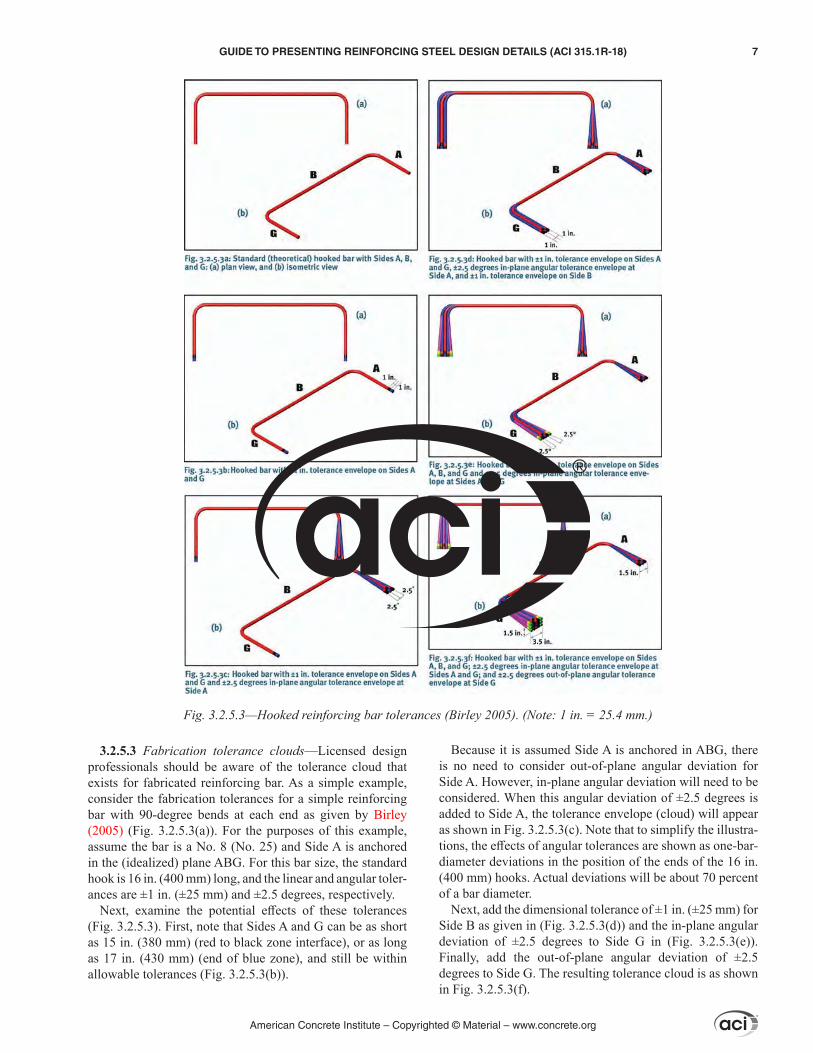
3.2.5.3 Fabrication tolerance clouds—Licensed design professionals should be aware of the tolerance cloud that exists for fabricated reinforcing bar. As a simple example, consider the fabrication tolerances for a simple reinforcing bar with 90-degree bends at each end as given by Birley (2005) (Fig. 3.2.5.3(a)). For the purposes of this example, assume the bar is a No. 8 (No. 25) and Side A is anchored in the (idealized) plane ABG. For this bar size, the standard hook is 16 in. (400 mm) long, and the linear and angular toler-ances are ±1 in. (±25 mm) and ±2.5 degrees, respectively.
Next, examine the potential effects of these tolerances (Fig. 3.2.5.3). First, note that Sides A and G can be as short as 15 in. (380 mm) (red to black zone interface), or as long as 17 in. (430 mm) (end of blue zone), and still be within allowable tolerances (Fig. 3.2.5.3(b)).
Because it is assumed Side A is anchored in ABG, there is no need to consider out-of-plane angular deviation for Side A. However, in-plane angular deviation will need to be considered. When this angular deviation of ±2.5 degrees is added to Side A, the tolerance envelope (cloud) will appear as shown in Fig. 3.2.5.3(c). Note that to simplify the illustra-tions, the effects of angular tolerances are shown as one-bar-diameter deviations in the position of the ends of the 16 in. (400 mm) hooks. Actual deviations will be about 70 percent of a bar diameter.
Next, add the dimensional tolerance of ±1 in. (±25 mm) for Side B as given in (Fig. 3.2.5.3(d)) and the in-plane angular deviation of ±2.5 degrees to Side G in (Fig. 3.2.5.3(e)). Finally, add the out-of-plane angular deviation of ±2.5 degrees to Side G. The resulting tolerance cloud is as shown in Fig. 3.2.5.3(f).
Fig. 3.2.5.3—Hooked reinforcing bar tolerances (Birley 2005). (Note: 1 in. = 25.4 mm.)
American Concrete Institute – Copyrighted © Material – www.concrete.org
GUIDE TO PRESENTING REINFORCING STEEL DESIGN DETAILS (ACI 315.1R-18) 7

3.2.5.4 Design considerations—The fabricated bar arriving at the construction site can be different from the bar the LDP or reinforcing bar detailer expected. Keeping this in mind during design could significantly reduce construc-tability problems. For instance, if our example bar was replaced with two hooked bars lapped in the middle (Fig. 3.2.5.4a), the only tolerance that might introduce problems would be in-plane angular deviation.
Because both hooks could be rotated, there would be no out-of-plane deviations. Further, because the lap length could be adjusted slightly in the field, there would be little chance of problems with the length of Side B.
Consideration of tolerances becomes even more of an issue when two or more bars are being assembled together in a structure. In this case, work with the accumulation of tolerances.
ACI 318-14 Section 25.3 restricts the minimum inside bend diameter of standard hook geometry for deformed bars in tension and the minimum inside bend diameters and standard hook geometry of stirrups, ties, and hoops. Primary factors affecting the minimum bend diameter are feasibility of bending without breakage and avoidance of crushing the concrete inside the bend. ACI 117 tolerance on these minimum inside bend diameters is –0 in. (–0 mm). Thus, bars cannot be requested, or expected, to be bent to a tighter diameter to solve a fit-up or congestion problem. Further-more, there is not a + tolerance for minimum bend diam-eter, and the bend diameter can be larger than the minimum due spring-back and other factors. Design drawings some-times illustrate hooks wrapping tightly around another bar with assumed bar positions based on the sum of the required cover, diameter of one bar, and half diameter of the other bar. A comparison of that incorrect assumption to the reality with a 6db minimum bend diameter is shown in Fig. 3.2.5.4b, and for larger bars, the minimum bend diameter could be 8db or 10db.
3.2.6 Forming tolerances3.2.6.1 General information—The last two sections
discussed tolerance clouds associated with fabrication and placement of reinforcing bars. While every builder strives to cast concrete to the precise dimensions indicated by the designer, reasonable constraints of time, technology, and
economy make this impractical. Therefore, it is important for designers to understand the forming tolerances associ-ated with concrete construction.
3.2.6.2 Forming tolerance clouds—Tolerances for forming concrete are found in ACI 117. The tolerances for cross-sectional dimensions of cast-in-place members vary with the overall dimension. Using the example from Section 3.2.4.2 of a 14 x 14 in. (355 x 355 mm) column, the tolerance is +1/2 in. or –3/8 in. (+13 mm or –10 mm). Ignoring vertical alignment, this produces the forming tolerance cloud shown in Fig. 3.2.6.2a, with a column having acceptable dimen-sions as large as 14-1/2 x 14-1/2 in. (368 x 368 mm) or as small as 13-5/8 x 13-5/8 in. (346 x 346 mm).
While it is highly unlikely that these small variations would create any constructability or design concerns with everything else being perfect, a different scenario arises when they are considered in conjunction with other possible tolerances.
With 1-1/2 in. (38 mm) cover, the design width for the column ties is 11 in. (280 mm), and the tolerance is ±1/2 in. (19 mm). Combining the maximum acceptable tie dimen-sions with the minimum acceptable column dimensions produces the configuration shown in Fig. 3.2.6.2b. With the reinforcing cage centered, the cover is reduced from the design value of 1-1/2 in. to 1-1/16 in. (38 mm to 27 mm) on all four sides. Recalling that the placement tolerances allow the cover to decrease to 1 in. (25 mm) minimum, the cage should be placed within ±1/16 in. (1.6 mm) of the center of the column in both directions if it is to meet tolerance requirements. Considering the straightness of the bars and forms, this could be difficult for the contractor.
Fig. 3.2.5.4a—Reducing tolerance problems by replacing single bar with two lapped bars. Note that the lap splice shown offset is for clarity only.
Fig. 3.2.5.4b—Comparison of minimum bend diameter position effect for a No. 7 (No. 22) bar.
American Concrete Institute – Copyrighted © Material – www.concrete.org
8 GUIDE TO PRESENTING REINFORCING STEEL DESIGN DETAILS (ACI 315.1R-18)

For the example of a 14 in. (355 mm)-thick wall that was discussed in previous sections, the situation is somewhat different because there are no tie tolerances to contend with. However, as seen in the following example, other issues arise that should be dealt with. The forming tolerance for the wall thickness allows the wall to be between 14-1/2 and 13-5/8 in. (368 and 346 mm) thick, as shown in Fig. 3.2.6.2c.
Reinforcement placement tolerances allow the 1-1/2 in. (38 mm) design cover on the outside face to be between 1 and 2 in. (25 and 50 mm) and the 3/4 in. (19 mm) design cover on the inside face to be between 1/2 and 1-1/4 in. (13 and 32 mm). The minimum wall thickness combined with the maximum cover on the outside face reinforcing is shown in Fig. 3.2.6.2d.
In this case, the original effective depth of 12 in. (250 mm) for the vertical No. 8 (No. 25) bars on the outside face has decreased to only 11-1/8 in. (282 mm). Assuming 4000 psi (25.6 MPa) concrete and Grade 60 reinforcement, this reduction in effective depth would result in a decrease in
nominal moment capacity from the original 45.1 kip·ft/ft (200 kNm/m) to 41.6 kip·ft/ft (185 kNm/m)—a 7.7 percent reduction due to forming and placement tolerances alone. The effect on moment strength would be even more drastic for thinner walls. To guard against this, Section 26.6.2.1(a) of ACI 318-14 places a tolerance on effective depth d of ±3/8 in. (10 mm) for d ≤ 8 in. (200 mm) and ±1/2 in. (±13 mm) for d > 8 in. (200 mm). These tolerances would produce a 4.4 percent reduction in nominal moment strength for the example wall considered herein; however, designers should realize that effective depth is not checked in the field. Rein-forcement is placed and tolerances checked relative to the formwork surfaces.
3.2.7 Confined reinforcing bars—Confined reinforcing bars add one more level of complexity to the tolerance issues described in previous sections. In the context of detailing and placing reinforcing steel, a confined bar is one that is restricted by face cover requirements at both ends. The best example of a confined reinforcing bar is a bar with hooks at each end, as would be seen in an elevated beam as shown in Fig. 3.2.7a.
On the surface, this does not seem to be significant, other than the tolerance issues previously discussed. However, when considering that in most cases there is adjacent rein-forcement for a beam, column, or wall, and that this double-hooked bar needs to fit within, the situation becomes much more complicated as shown in Fig. 3.2.7b.
Fig. 3.2.6.2a—Forming tolerance cloud for the column. (Note: 1 in. = 25.4 mm.)
Fig. 3.2.6.2b—Combining the maximum acceptable tie dimensions with the minimum acceptable column dimen-sions effectively limits placing tolerances to ±1/16 in. (±2 mm). (Note: 1 in. = 25.4 mm.)
Fig. 3.2.6.2c—Forming tolerance cloud for the wall. (Note: 1 in. = 25.4 mm.)
Fig. 3.2.6.2d—Minimum acceptable wall thickness and maximum acceptable cover combine to produce an effective depth for outside face vertical bars violating ACI 318 toler-ances (1 in. = 25.4 mm).
American Concrete Institute – Copyrighted © Material – www.concrete.org
GUIDE TO PRESENTING REINFORCING STEEL DESIGN DETAILS (ACI 315.1R-18) 9
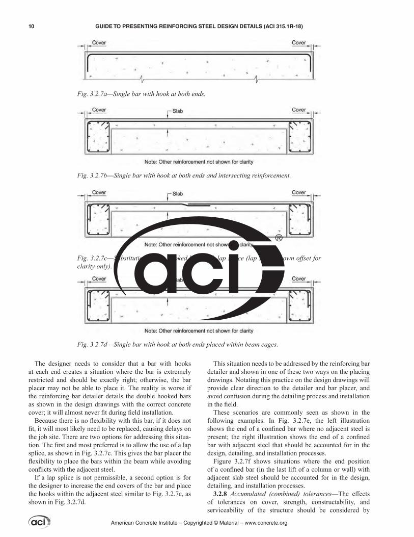
The designer needs to consider that a bar with hooks at each end creates a situation where the bar is extremely restricted and should be exactly right; otherwise, the bar placer may not be able to place it. The reality is worse if the reinforcing bar detailer details the double hooked bars as shown in the design drawings with the correct concrete cover; it will almost never fit during field installation.
Because there is no flexibility with this bar, if it does not fit, it will most likely need to be replaced, causing delays on the job site. There are two options for addressing this situa-tion. The first and most preferred is to allow the use of a lap splice, as shown in Fig. 3.2.7c. This gives the bar placer the flexibility to place the bars within the beam while avoiding conflicts with the adjacent steel.
If a lap splice is not permissible, a second option is for the designer to increase the end covers of the bar and place the hooks within the adjacent steel similar to Fig. 3.2.7c, as shown in Fig. 3.2.7d.
This situation needs to be addressed by the reinforcing bar detailer and shown in one of these two ways on the placing drawings. Notating this practice on the design drawings will provide clear direction to the detailer and bar placer, and avoid confusion during the detailing process and installation in the field.
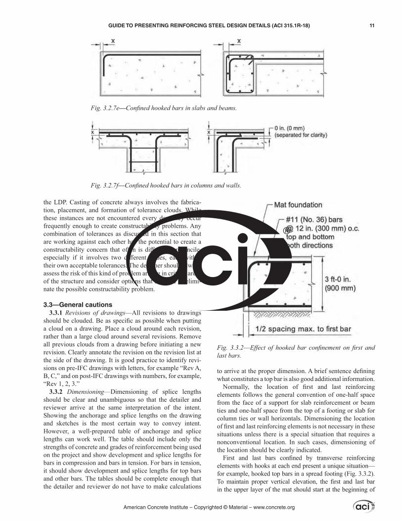
These scenarios are commonly seen as shown in the following examples. In Fig. 3.2.7e, the left illustration shows the end of a confined bar where no adjacent steel is present; the right illustration shows the end of a confined bar with adjacent steel that should be accounted for in the design, detailing, and installation processes.
Figure 3.2.7f shows situations where the end position of a confined bar (in the last lift of a column or wall) with adjacent slab steel should be accounted for in the design, detailing, and installation processes.
3.2.8 Accumulated (combined) tolerances—The effects of tolerances on cover, strength, constructability, and serviceability of the structure should be considered by
Fig. 3.2.7a—Single bar with hook at both ends.
Fig. 3.2.7b—Single bar with hook at both ends and intersecting reinforcement.
Fig. 3.2.7c—Substitution of two hooked bars with lap splice (lap splice shown offset for clarity only).
Fig. 3.2.7d—Single bar with hook at both ends placed within beam cages.
American Concrete Institute – Copyrighted © Material – www.concrete.org
10 GUIDE TO PRESENTING REINFORCING STEEL DESIGN DETAILS (ACI 315.1R-18)
the LDP. Casting of concrete always involves the fabrica-tion, placement, and formation of tolerance clouds. While these instances are not encountered every day, they occur frequently enough to create constructability problems. Any combination of tolerances as discussed in this section that are working against each other has the potential to create a constructability concern that often is difficult to reconcile, especially if it involves two different trades, each within their own acceptable tolerances. The designer should always assess the risk of this kind of problem arising in critical areas of the structure and consider options that mitigate or elimi-nate the possible constructability problem.
3.3—General cautions3.3.1 Revisions of drawings—All revisions to drawings
should be clouded. Be as specific as possible when putting a cloud on a drawing. Place a cloud around each revision, rather than a large cloud around several revisions. Remove all previous clouds from a drawing before initiating a new revision. Clearly annotate the revision on the revision list at the side of the drawing. It is good practice to identify revi-sions on pre-IFC drawings with letters, for example “Rev A, B, C,” and on post-IFC drawings with numbers, for example, “Rev 1, 2, 3.”
3.3.2 Dimensioning—Dimensioning of splice lengths should be clear and unambiguous so that the detailer and reviewer arrive at the same interpretation of the intent. Showing the anchorage and splice lengths on the drawing and sketches is the most certain way to convey intent. However, a well-prepared table of anchorage and splice lengths can work well. The table should include only the strengths of concrete and grades of reinforcement being used on the project and show development and splice lengths for bars in compression and bars in tension. For bars in tension, it should show development and splice lengths for top bars and other bars. The tables should be complete enough that the detailer and reviewer do not have to make calculations
to arrive at the proper dimension. A brief sentence defining what constitutes a top bar is also good additional information.
Normally, the location of first and last reinforcing elements follows the general convention of one-half space from the face of a support for slab reinforcement or beam ties and one-half space from the top of a footing or slab for column ties or wall horizontals. Dimensioning the location of first and last reinforcing elements is not necessary in these situations unless there is a special situation that requires a nonconventional location. In such cases, dimensioning of the location should be clearly indicated.
First and last bars confined by transverse reinforcing elements with hooks at each end present a unique situation—for example, hooked top bars in a spread footing (Fig. 3.3.2). To maintain proper vertical elevation, the first and last bar in the upper layer of the mat should start at the beginning of
Fig. 3.2.7e—Confined hooked bars in slabs and beams.
Fig. 3.2.7f—Confined hooked bars in columns and walls.
Fig. 3.3.2––Effect of hooked bar confinement on first and last bars.
American Concrete Institute – Copyrighted © Material – www.concrete.org
GUIDE TO PRESENTING REINFORCING STEEL DESIGN DETAILS (ACI 315.1R-18) 11
the radius of the bend, not at the specified clearance from the concrete face. In such a case, one could question if the LDP intends that spacing be from the center lines of the first and last bars or from clearance-to-clearance. In this situation, it would be better for the LDP to give a quantity of reinforcing elements or area of steel required rather than spacing of the bars.
3.3.3 Field cutting of bars—Methods for field cutting any reinforcing steel, other than saw cutting, should be approved by the LDP. If the location is confined, the only practical alternative is to flame-cut the reinforcement. Bar placers are trained in the use of a cutting torch and can make the cut without any deleterious effect on the steel material. ACI 301 prohibits flame cutting of epoxy-coated bars. If the LDP has some compelling reason against flame-cutting uncoated rein-forcement, this should be stated clearly in the general notes. In the absence of such an instruction, the bar placer will assume that flame-cutting uncoated reinforcement is permitted.
3.3.4 Field bending of bars—Field bending of embedded reinforcement may occasionally be required due to incor-rect fabrication or placing, or due to a design change that requires the reinforcement to be reconfigured. ACI 301 specifies requirements for field bending. Small bars can usually be bent cold, especially if it is their first bend; that is, a straight wall vertical bar being bent into a slab. Large bars require preheating. Straightening and rebending of previ-ously bent reinforcement should be approached cautiously. With caution, and if the bend radius is sufficiently large, the bars should not be affected. Other more extreme situations may require that the LDP set parameters for the process and ensure that the operation is supervised and executed by qual-ified personnel, subject to on-site inspector review.
3.3.5 Mechanical connectors—Mechanical connectors require similar considerations to those for splices. The LDP should indicate on the drawing where they are to be used. Specific limitations should be listed such as spacing, stagger, and clearance. The type of connector should be listed along with the manufacturer if this is critical.
3.3.6 Mixing grades of steel on a project—Frequently a project will require more than one grade of steel or more than one kind of coating. The LDP should be specific about where the various grades or coatings are to be used. This informa-tion can be given in the general notes and on the drawings to avoid any ambiguity about intent. Mixing grades or coat-ings in a single member should be avoided if possible. For example, do not call for coated top reinforcement in a beam while the remainder of the reinforcement is uncoated bar.
3.4—Drawing types and purposesDesign drawings for concrete structures are developed
by LDPs. Those documents render the design and establish the design predicates for the construction. They include, at a minimum, building code required information for review by the pertinent code authority.
Design drawings are also contract documents. These form the contractual basis between the general contractor and owner. They should graphically show the scope, extent, and character of the construction work.
Placing drawings for reinforcement (and shop drawings for other trades) include graphics and schedules, and are specifically prepared by the contractor to illustrate specific portions of the construction work. These drawings, whether approved or not, do not become contact documents or design plans.
The normal process is for the designer to render the design and for the contractor (and subcontractors) to prepare trade-specific drawings extracted from the design plans that define the particular work. Usually the trade-specific drawings are submitted to the designer of record for review to confirm that contractor’s interpretation of the design intent is correct.
Field construction is then conducted from the approved trade-specific drawings in conformance with the contract documents.
CHAPTER 4—STRUCTURAL DRAWINGS
4.1—ScopeThis chapter describes information typically necessary to
the structural design drawings, so the scope of the construc-tion based on the design plans can be established. Normally, engineering offices develop an office standard suitable to their practice area for the presentation of design informa-tion. This guide, as an example, presents the project sheet order found in the United States National CAD Standard® (NCS-V6), as outlined in 4.3.
4.2—GeneralStructural drawings are prepared by a licensed design
professional (LDP). The drawings, along with the project specifications, form the bulk of the contract documents. Structural drawings should contain an adequate set of notes, instructions, and information necessary to permit the rein-forcing steel detailer to produce reinforcing steel placing drawings. Each sheet should have a title block, production data, and a drawing area as shown in Fig. 4.2.
The drawing area, which is the largest portion of the sheet, is where technical information is presented. Examples of technical information are the overall framing plan, sections, and details needed to illustrate information at specific areas, and additional notes as required.
The production data area is located in the left margin of the sheet and includes information such as the computer-aided design (CAD) filename and path to the file, default settings, printer/plotter commands, date and time of plot, overlay drafting control data, and reference files.
The title block area, which is located to the right side of the sheet, usually includes the designer’s name, address, and logo; basic information about the project, including location of the work site, owner, and project name; an information block regarding issue type of this sheet, such as addendum, design development, bidding, and bulletin; a sheet respon-sibility block that indicates the project manager, engineer, draftsman, and reviewer of the information on the drawing; a sheet title block; and a sheet numbering block. The title block also contains space for a disclaimer, if it is a prelimi-
American Concrete Institute – Copyrighted © Material – www.concrete.org
12 GUIDE TO PRESENTING REINFORCING STEEL DESIGN DETAILS (ACI 315.1R-18)
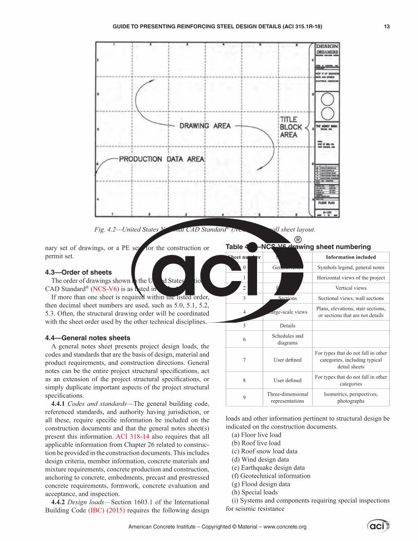
nary set of drawings, or a PE seal for the construction or permit set.
4.3—Order of sheetsThe order of drawings shown in the United States National
CAD Standard® (NCS-V6) is as listed in Table 4.3.If more than one sheet is required within the listed order,
then decimal sheet numbers are used, such as 5.0, 5.1, 5.2, 5.3. Often, the structural drawing order will be coordinated with the sheet order used by the other technical disciplines.
4.4—General notes sheetsA general notes sheet presents project design loads, the
codes and standards that are the basis of design, material and product requirements, and construction directions. General notes can be the entire project structural specifications, act as an extension of the project structural specifications, or simply duplicate important aspects of the project structural specifications.
4.4.1 Codes and standards—The general building code, referenced standards, and authority having jurisdiction, or all these, require specific information be included on the construction documents and that the general notes sheet(s) present this information. ACI 318-14 also requires that all applicable information from Chapter 26 related to construc-tion be provided in the construction documents. This includes design criteria, member information, concrete materials and mixture requirements, concrete production and construction, anchoring to concrete, embedments, precast and prestressed concrete requirements, formwork, concrete evaluation and acceptance, and inspection.
4.4.2 Design loads—Section 1603.1 of the International Building Code (IBC) (2015) requires the following design
loads and other information pertinent to structural design be indicated on the construction documents.
(a) Floor live load(b) Roof live load(c) Roof snow load data(d) Wind design data(e) Earthquake design data(f) Geotechnical information(g) Flood design data(h) Special loads(i) Systems and components requiring special inspections
for seismic resistance
Fig. 4.2—United States National CAD Standard® (NCS-V6) overall sheet layout.
Table 4.3—NCS-V6 drawing sheet numberingSheet number Sheet title Information included
0 General notes Symbols legend, general notes
1 Plans Horizontal views of the project
2 Elevations Vertical views
3 Sections Sectional views, wall sections
4 Large-scale views Plans, elevations, stair sections, or sections that are not details
5 Details
6 Schedules and diagrams
7 User definedFor types that do not fall in other
categories, including typical detail sheets
8 User defined For types that do not fall in other categories
9 Three-dimensional representations
Isometrics, perspectives, photographs
American Concrete Institute – Copyrighted © Material – www.concrete.org
GUIDE TO PRESENTING REINFORCING STEEL DESIGN DETAILS (ACI 315.1R-18) 13
Design loads are presented on the general notes sheet. Floor live loads, roof live loads, snow loads, and other simple gravity loads are commonly shown in a table. Basic wind load criteria assumptions and, when necessary, wind-loading diagrams are included. Earthquake design data are usually presented as a list of the different criteria used to develop the design earthquake loads. It is preferred to indi-cate if and where live load reductions were applied.
Geotechnical design information shown is usually supplied to the structural designer in a geotechnical report. This can be presented as a note when the soil and water table on-site is relatively consistent, or in a table format when there is significant soil or water table variability.
Flood design data and criteria used to determine the flood design loads are typically shown using notes.
Special loads not included in the code-required live loads are also noted in the table that includes live loads. Examples of such loads are architectural features, partition live loads, ceiling and hanging loads, and superimposed dead loads. A diagram might be needed for heavy pieces of equipment, such as forklifts, with their assumed wheel spacing and axle loads.
Showing the self-weight of the structure is not a require-ment of the code. However, an indication of where light-weight, normalweight, and heavyweight concrete is used should be provided on the drawings so that the self-weight of the structure can be reasonably determined by the form-work engineer.
4.4.3 Specifications—The first concrete general note is commonly a reference to require construction be in accor-dance with ACI 301. The LDP ensures that the construc-tion documents meet code provisions; therefore, requiring the contractor to conform to ACI 318 is not appropriate, as it provides code requirements to the LDP and not the contractor or materials supplier. By incorporating ACI 301 by reference into the construction documents and using the ACI 301 mandatory and optional checklists, the concrete materials and construction requirements will satisfy ACI 318. In addition, ACI 301 also specifies that fabrication and construction tolerances should comply with ACI 117.
ACI 301 contains the following three checklists: manda-tory requirements, optional requirements, and submittals. The LDP is often also the specifier on a project and should go through these checklists and make necessary exceptions to ACI 301 in the construction documents. The general notes sheet is a convenient way to communicate any necessary exceptions to ACI 301.
4.4.4 Concrete notes—The Mandatory Requirements Checklist items in ACI 301 that are related to concrete can be specified in the general concrete notes and indicate that the construction documents include:
(a) Exposure class and specified compressive strength, fc′, for different concrete elements
(b) Handling, placing, and constructing requirements(c) Designations and requirements for architectural
concrete, lightweight concrete, mass concrete, post-tensioned concrete, shrinkage-compensating concrete, industrial floor slabs, tilt-up construction, and precast concrete
Concrete general notes can show this information in a table with each structural element type, along with its corre-sponding exposure class, specified compressive strength, and other requirements.
Construction documents should also indicate any excep-tions to the default requirements of ACI 301. ACI 301 lists possible exceptions in the Optional Requirements Checklist. Concrete general notes often contain the following optional requirements checklist exceptions to ACI 301 default requirements:
(a) Air entrainment in percentage (%), along with the respective tolerance
(b) Slump in inches (in.), along with the respective tolerance
(c) When high-range water-reducing admixtures are allowed or required
(d) Additional testing and inspection services4.4.5 Reinforcement notes—ACI 301 Mandatory Require-
ments Checklist items related to reinforcing steel can be specified in the general reinforcement notes and indicate that the construction documents include:
(a) Type and grade of reinforcing steel(b) Bar development and splice lengths and locations(c) Types of reinforcement supports and locations used
within the structure(d) Cover for headed shear stud reinforcement and headed
reinforcing barsConstruction documents should indicate any exceptions to
the default requirements of ACI 301. ACI 301 lists possible exceptions to the default requirements in the Optional Requirements Checklist. Some exceptions to ACI 301 default requirements can include the following:
(a) Weldability of bars(b) Concrete cover to reinforcement(c) Specialty item type and grade(d) Coatings such as epoxy or zinc where applicable(e) Permitting field cutting of reinforcement and cutting
methodsReinforcement requires concrete cover to protect the steel
from corrosion. ACI 301 Table 3.3.2.3 shows concrete cover requirements for specific members. The concrete cover requirements for a project are typically shown in a table or list showing the type of member, concrete exposure, type of reinforcement, and concrete cover requirements for each. If there are questionable locations on a specific project, the contract documents should indicate the specific concrete cover requirement controls at each location; an example is fire-rated elements.
When proprietary reinforcement products are required on a project, they can be specified in the general notes.
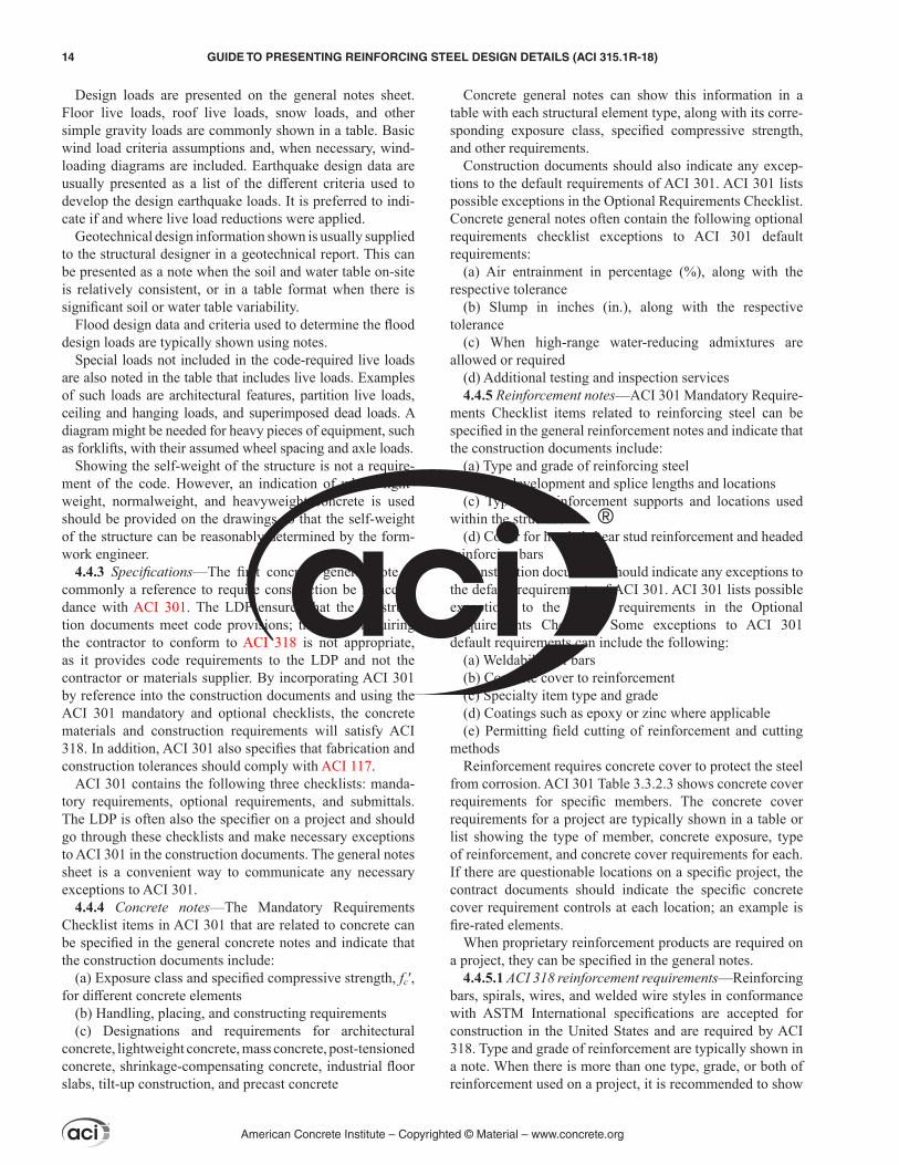
4.4.5.1 ACI 318 reinforcement requirements—Reinforcing bars, spirals, wires, and welded wire styles in conformance with ASTM International specifications are accepted for construction in the United States and are required by ACI 318. Type and grade of reinforcement are typically shown in a note. When there is more than one type, grade, or both of reinforcement used on a project, it is recommended to show
American Concrete Institute – Copyrighted © Material – www.concrete.org
14 GUIDE TO PRESENTING REINFORCING STEEL DESIGN DETAILS (ACI 315.1R-18)
this information in a table indicating the type and grade used in specific parts of the structure (Fig. 4.4.5.1).
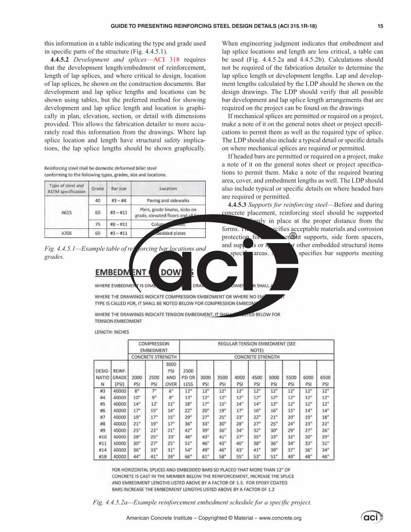
4.4.5.2 Development and splices—ACI 318 requires that the development length/embedment of reinforcement, length of lap splices, and where critical to design, location of lap splices, be shown on the construction documents. Bar development and lap splice lengths and locations can be shown using tables, but the preferred method for showing development and lap splice length and location is graphi-cally in plan, elevation, section, or detail with dimensions provided. This allows the fabrication detailer to more accu-rately read this information from the drawings. Where lap splice location and length have structural safety implica-tions, the lap splice lengths should be shown graphically.
When engineering judgment indicates that embedment and lap splice locations and length are less critical, a table can be used (Fig. 4.4.5.2a and 4.4.5.2b). Calculations should not be required of the fabrication detailer to determine the lap splice length or development lengths. Lap and develop-ment lengths calculated by the LDP should be shown on the design drawings. The LDP should verify that all possible bar development and lap splice length arrangements that are required on the project can be found on the drawings
If mechanical splices are permitted or required on a project, make a note of it on the general notes sheet or project specifi-cations to permit them as well as the required type of splice. The LDP should also include a typical detail or specific details on where mechanical splices are required or permitted.
If headed bars are permitted or required on a project, make a note of it on the general notes sheet or project specifica-tions to permit them. Make a note of the required bearing area, cover, and embedment lengths as well. The LDP should also include typical or specific details on where headed bars are required or permitted.
4.4.5.3 Supports for reinforcing steel—Before and during concrete placement, reinforcing steel should be supported and held firmly in place at the proper distance from the forms. The LDP specifies acceptable materials and corrosion protection for reinforcement supports, side form spacers, and supports or spacers for other embedded structural items or specific areas. ACI 301 specifies bar supports meeting
Fig. 4.4.5.1—Example table of reinforcing bar locations and grades.
Fig. 4.4.5.2a—Example reinforcement embedment schedule for a specific project.
American Concrete Institute – Copyrighted © Material – www.concrete.org
GUIDE TO PRESENTING REINFORCING STEEL DESIGN DETAILS (ACI 315.1R-18) 15

the requirements of the Concrete Reinforcing Steel Institute (CRSI) RB4.1.
If the construction documents only state that reinforce-ment needs to be accurately placed, adequately supported, and secured against displacement within permitted toler-ances, the contractor selects the type, class, and spacing of wire supports, precast blocks, composite (plastic), or other materials to use for each area.
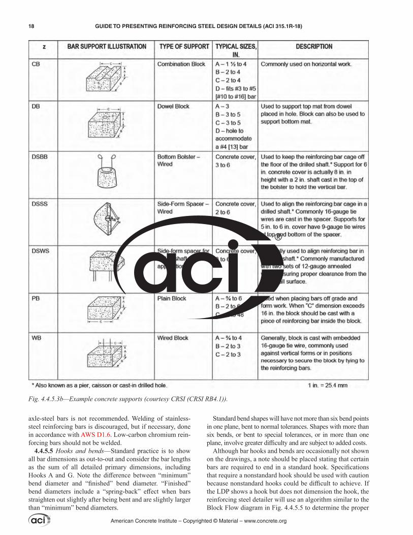
CRSI RB4.1 describes the various types of wire, composite, and precast bar supports. There are three common material types of bar supports: wire bar supports shown in Fig. 4.4.5.3a, precast concrete block bar supports shown in Fig. 4.4.5.3b, and composite (plastic) bar supports shown in Fig 4.4.5.3c.
Certain reinforcement support types can cause aesthetic issues. For example, if precast blocks are used and the surface has a sand-blasted finish, the different texture and color between the precast blocks and the cast-in-place concrete might be objectionable. Also, Class 3 wire bar supports could leave rust stains on the exposed concrete surfaces due to corrosion. A common sub-type of wire bar supports is plastic-tipped wire bar supports that are often used when surface corrosion spots would be of concern. The LDP should clearly define areas on the drawings where
specific types of supports are needed to avoid aesthetic prob-lems and future repairs that can be costly.
Beam bolsters support bottom beam reinforcement and are placed in the beam form, usually perpendicular to the axis of the beam under the stirrups. Beams can also be supported with individual chairs or blocks placed under the beam stirrups.
Bar supports are furnished for bottom bars in grade beams or slabs-on-ground only if required in the construction docu-ments. For a structural element, the LDP should specify bar supports for the bottom bars in grade beams or slabs-on-ground. Aesthetics are not a concern in the bottom of a slab-on-ground or grade beam, which allows the use of precast blocks for bar supports.
Side form spacers (Fig. 4.4.5.3d) can be specified for use, but are usually selected by the contractor.
4.4.5.4 Weldability of bars—The weldability of steel is established by its chemical composition. The American Welding Society (AWS) D1.4 sets the minimum preheat and interpass temperatures and provides the applicable welding procedures. Carbon steel bars conforming to ASTM A615/A615M are weldable with appropriate preheating. Only rein-forcing bars conforming to ASTM A706/A706M are preap-proved for welding without preheating. Welding of rail-and
Fig. 4.4.5.2b—Example reinforcement lap schedule for a specific project.
American Concrete Institute – Copyrighted © Material – www.concrete.org
16 GUIDE TO PRESENTING REINFORCING STEEL DESIGN DETAILS (ACI 315.1R-18)
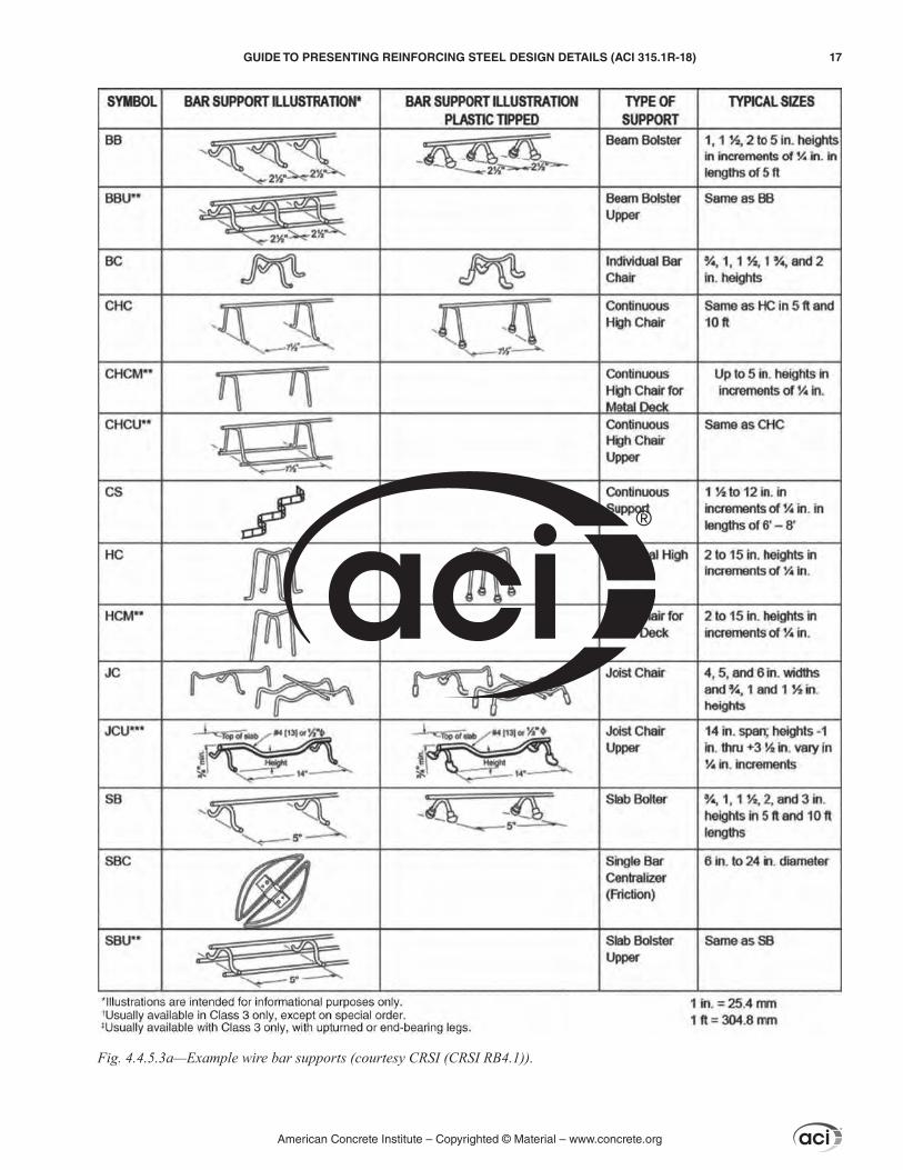
Fig. 4.4.5.3a—Example wire bar supports (courtesy CRSI (CRSI RB4.1)).
American Concrete Institute – Copyrighted © Material – www.concrete.org
GUIDE TO PRESENTING REINFORCING STEEL DESIGN DETAILS (ACI 315.1R-18) 17
axle-steel bars is not recommended. Welding of stainless-steel reinforcing bars is discouraged, but if necessary, done in accordance with AWS D1.6. Low-carbon chromium rein-forcing bars should not be welded.
4.4.5.5 Hooks and bends—Standard practice is to show all bar dimensions as out-to-out and consider the bar lengths as the sum of all detailed primary dimensions, including Hooks A and G. Note the difference between “minimum” bend diameter and “finished” bend diameter. “Finished” bend diameters include a “spring-back” effect when bars straighten out slightly after being bent and are slightly larger than “minimum” bend diameters.
Standard bend shapes will have not more than six bend points in one plane, bent to normal tolerances. Shapes with more than six bends, or bent to special tolerances, or in more than one plane, involve greater difficulty and are subject to added costs.
Although bar hooks and bends are occasionally not shown on the drawings, a note should be placed stating that certain bars are required to end in a standard hook. Specifications that require a nonstandard hook should be used with caution because nonstandard hooks could be difficult to achieve. If the LDP shows a hook but does not dimension the hook, the reinforcing steel detailer will use an algorithm similar to the Block Flow diagram in Fig. 4.4.5.5 to determine the proper
Fig. 4.4.5.3b—Example concrete supports (courtesy CRSI (CRSI RB4.1)).
American Concrete Institute – Copyrighted © Material – www.concrete.org
18 GUIDE TO PRESENTING REINFORCING STEEL DESIGN DETAILS (ACI 315.1R-18)

Fig. 4.4.5.3c—Example plastic supports (courtesy CRSI (CRSI RB4.1)).
American Concrete Institute – Copyrighted © Material – www.concrete.org
GUIDE TO PRESENTING REINFORCING STEEL DESIGN DETAILS (ACI 315.1R-18) 19
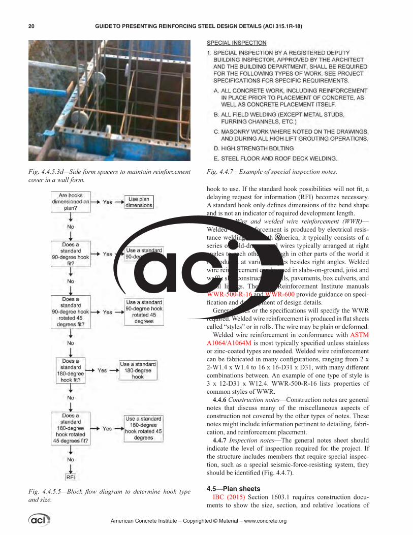
hook to use. If the standard hook possibilities will not fit, a delaying request for information (RFI) becomes necessary. A standard hook only defines dimensions of the bend shape and is not an indicator of required development length.
4.4.5.6 Wire and welded wire reinforcement (WWR)—Welded wire reinforcement is produced by electrical resis-tance welding. In North America, it typically consists of a series of cold-drawn steel wires typically arranged at right angles to each other, although in other parts of the world it is produced at various angles besides right angles. Welded wire reinforcement can be used in slabs-on-ground, joist and waffle slab construction, walls, pavements, box culverts, and canal linings. The Wire Reinforcement Institute manuals WWR-500-R-16 and WWR-600 provide guidance on speci-fication and development of design details.
General notes or the specifications will specify the WWR required. Welded wire reinforcement is produced in flat sheets called “styles” or in rolls. The wire may be plain or deformed.
Welded wire reinforcement in conformance with ASTM A1064/A1064M is most typically specified unless stainless or zinc-coated types are needed. Welded wire reinforcement can be fabricated in many configurations, ranging from 2 x 2-W1.4 x W1.4 to 16 x 16-D31 x D31, with many different combinations between. An example of one type of style is 3 x 12-D31 x W12.4. WWR-500-R-16 lists properties of common styles of WWR.
4.4.6 Construction notes—Construction notes are general notes that discuss many of the miscellaneous aspects of construction not covered by the other types of notes. These notes might include information pertinent to detailing, fabri-cation, and reinforcement placement.
4.4.7 Inspection notes—The general notes sheet should indicate the level of inspection required for the project. If the structure includes members that require special inspec-tion, such as a special seismic-force-resisting system, they should be identified (Fig. 4.4.7).
4.5—Plan sheetsIBC (2015) Section 1603.1 requires construction docu-
ments to show the size, section, and relative locations of
Fig. 4.4.5.3d—Side form spacers to maintain reinforcement cover in a wall form.
Fig. 4.4.5.5—Block flow diagram to determine hook type and size.
Fig. 4.4.7—Example of special inspection notes.
American Concrete Institute – Copyrighted © Material – www.concrete.org
20 GUIDE TO PRESENTING REINFORCING STEEL DESIGN DETAILS (ACI 315.1R-18)
structural members with floor levels, column centers, and offsets dimensioned. A plan drawing provides informa-tion about an identified building floor, including overall geometry and dimensions, and concrete member width and thicknesses, either directly or by a designation keyed to a schedule, as well as reinforcement information for concrete members either directly, or by a designation keyed to a schedule. A plan drawing can include a general reference to other sheets, such as an elevation or detail sheet. A floor plan also includes orientation information, such as column line numbers, a north arrow, top of concrete relative to a datum, and general notes specific to the floor plan.
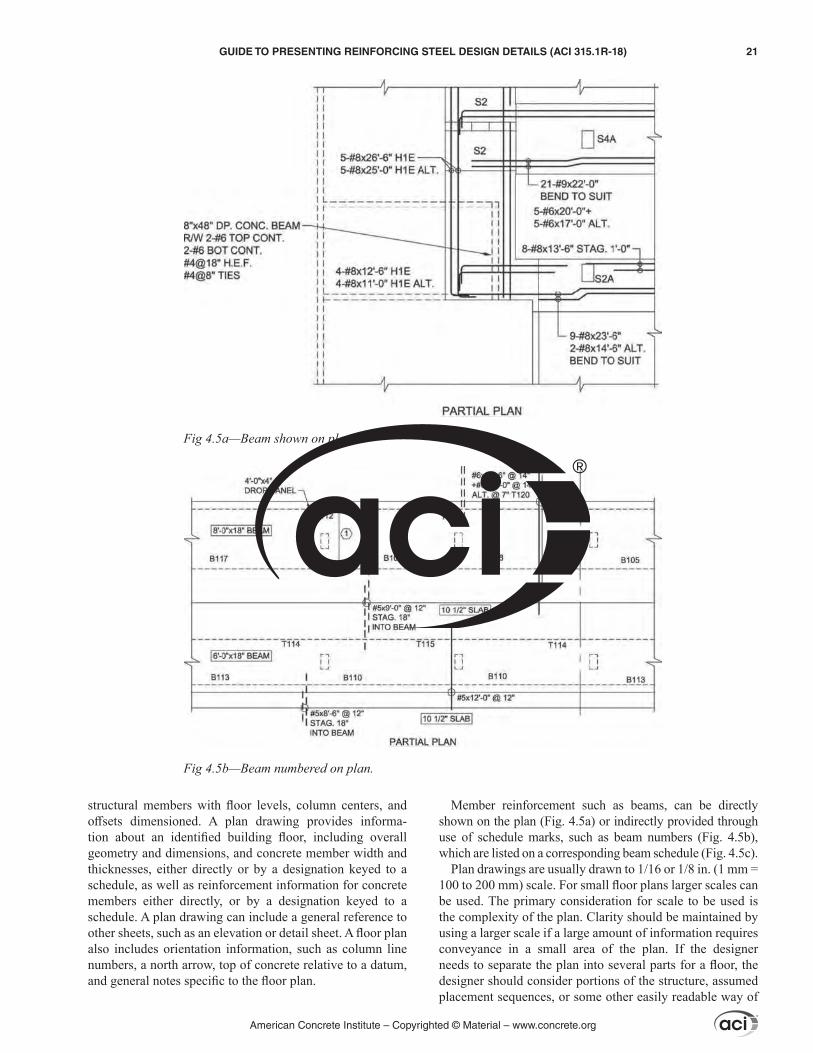
Member reinforcement such as beams, can be directly shown on the plan (Fig. 4.5a) or indirectly provided through use of schedule marks, such as beam numbers (Fig. 4.5b), which are listed on a corresponding beam schedule (Fig. 4.5c).
Plan drawings are usually drawn to 1/16 or 1/8 in. (1 mm = 100 to 200 mm) scale. For small floor plans larger scales can be used. The primary consideration for scale to be used is the complexity of the plan. Clarity should be maintained by using a larger scale if a large amount of information requires conveyance in a small area of the plan. If the designer needs to separate the plan into several parts for a floor, the designer should consider portions of the structure, assumed placement sequences, or some other easily readable way of
Fig 4.5a—Beam shown on plan.
Fig 4.5b—Beam numbered on plan.
American Concrete Institute – Copyrighted © Material – www.concrete.org
GUIDE TO PRESENTING REINFORCING STEEL DESIGN DETAILS (ACI 315.1R-18) 21
breaking the plan into smaller parts. Match lines, indicating the adjacency of the separated parts, are typically used.
Because plans only provide information in the horizontal direction, use section cuts and elevations to clarify geometric and reinforcement information in the vertical direction. A section cut is indicated by a directional mark or cut drawn on the floor plan (Fig. 4.5d and 4.5e).
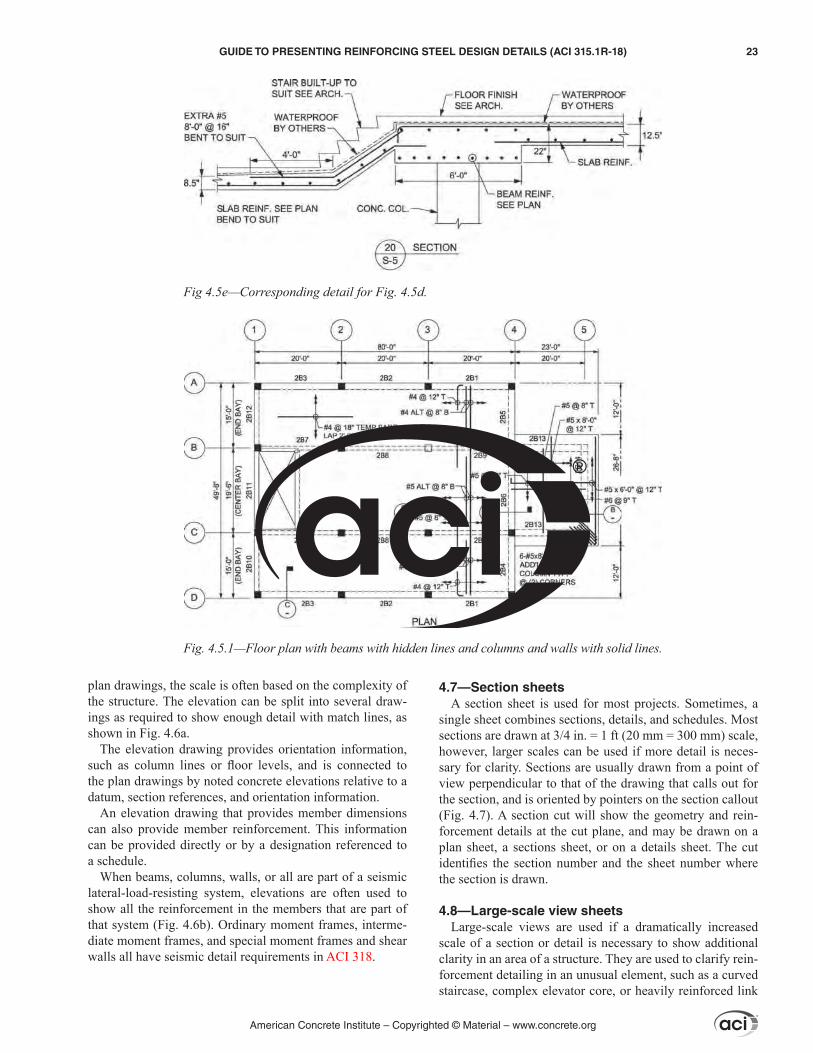
4.5.1 Plan graphics and member geometry—The assumed view point for a plan drawing is above the slab on each floor level of a structure (Fig. 4.5.1). Therefore, slab edges are shown as solid lines on the plan drawings. Concrete beams’ and girders’ locations are usually shown as hidden on the plan drawings because they are typically below the surface
of the slab. Columns and walls above the slab are shown with solid lines.
Columns and walls that are shown solid extend above the slab on the plan. These vertical members of the structure will be shown on all the plans from their lowest elevation in the structure, usually the foundation but occasionally a transfer girder or slab, to their highest elevation in the structure, usually the top tier where they will be drawn as hidden.
Foundations are drawn as hidden when they are below the slab-on-ground and solid when not covered by structural members or slab-on-ground concrete. Soil is not considered a structural member for this purpose.
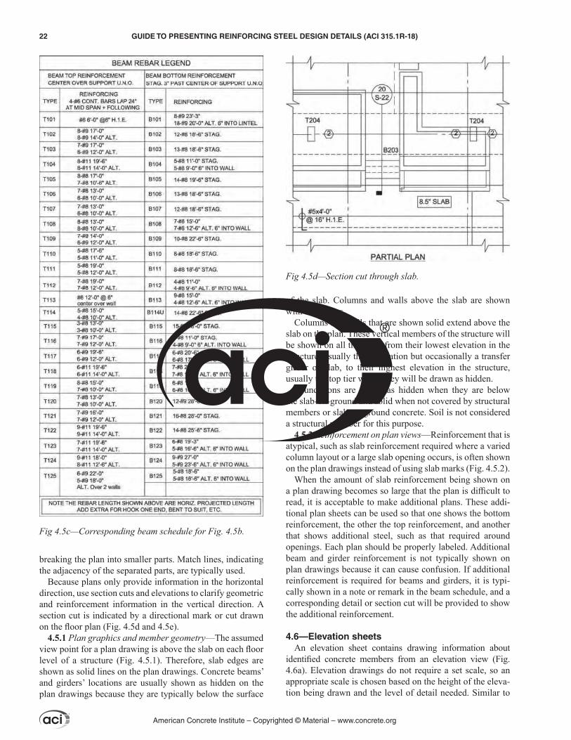
4.5.2 Reinforcement on plan views—Reinforcement that is atypical, such as slab reinforcement required where a varied column layout or a large slab opening occurs, is often shown on the plan drawings instead of using slab marks (Fig. 4.5.2).
When the amount of slab reinforcement being shown on a plan drawing becomes so large that the plan is difficult to read, it is acceptable to make additional plans. These addi-tional plan sheets can be used so that one shows the bottom reinforcement, the other the top reinforcement, and another that shows additional steel, such as that required around openings. Each plan should be properly labeled. Additional beam and girder reinforcement is not typically shown on plan drawings because it can cause confusion. If additional reinforcement is required for beams and girders, it is typi-cally shown in a note or remark in the beam schedule, and a corresponding detail or section cut will be provided to show the additional reinforcement.
4.6—Elevation sheetsAn elevation sheet contains drawing information about
identified concrete members from an elevation view (Fig. 4.6a). Elevation drawings do not require a set scale, so an appropriate scale is chosen based on the height of the eleva-tion being drawn and the level of detail needed. Similar to
Fig 4.5c—Corresponding beam schedule for Fig. 4.5b.
Fig 4.5d—Section cut through slab.
American Concrete Institute – Copyrighted © Material – www.concrete.org
22 GUIDE TO PRESENTING REINFORCING STEEL DESIGN DETAILS (ACI 315.1R-18)
plan drawings, the scale is often based on the complexity of the structure. The elevation can be split into several draw-ings as required to show enough detail with match lines, as shown in Fig. 4.6a.
The elevation drawing provides orientation information, such as column lines or floor levels, and is connected to the plan drawings by noted concrete elevations relative to a datum, section references, and orientation information.
An elevation drawing that provides member dimensions can also provide member reinforcement. This information can be provided directly or by a designation referenced to a schedule.
When beams, columns, walls, or all are part of a seismic lateral-load-resisting system, elevations are often used to show all the reinforcement in the members that are part of that system (Fig. 4.6b). Ordinary moment frames, interme-diate moment frames, and special moment frames and shear walls all have seismic detail requirements in ACI 318.
4.7—Section sheetsA section sheet is used for most projects. Sometimes, a
single sheet combines sections, details, and schedules. Most sections are drawn at 3/4 in. = 1 ft (20 mm = 300 mm) scale, however, larger scales can be used if more detail is neces-sary for clarity. Sections are usually drawn from a point of view perpendicular to that of the drawing that calls out for the section, and is oriented by pointers on the section callout (Fig. 4.7). A section cut will show the geometry and rein-forcement details at the cut plane, and may be drawn on a plan sheet, a sections sheet, or on a details sheet. The cut identifies the section number and the sheet number where the section is drawn.
4.8—Large-scale view sheetsLarge-scale views are used if a dramatically increased
scale of a section or detail is necessary to show additional clarity in an area of a structure. They are used to clarify rein-forcement detailing in an unusual element, such as a curved staircase, complex elevator core, or heavily reinforced link
Fig 4.5e—Corresponding detail for Fig. 4.5d.
Fig. 4.5.1—Floor plan with beams with hidden lines and columns and walls with solid lines.
American Concrete Institute – Copyrighted © Material – www.concrete.org
GUIDE TO PRESENTING REINFORCING STEEL DESIGN DETAILS (ACI 315.1R-18) 23

beam. These sheets are rarely titled “large-scale views,” but instead, usually titled by what is being shown on the sheet. For example, “Stairs – Plans and Sections” could be an example title for a large-scale view sheet for a stair tower.
4.9—Detail sheetsDetails are usually drawn from the same point of view as
the drawing that calls out the detail (Fig. 4.9a).A separate detail sheet is usually used on a project.
However, small projects may have a single sheet that combines sections, details, and schedules. Many details are drawn at 3/8 to 1 in. = 1 ft (1 mm = 10 to 50 mm) scales, but larger scales are used if needed for clarity. In heavily congested areas, using full-scale drawings is suggested to help with checking constructability.
Details that are applicable to commonly encountered conditions are usually placed on “typical details” sheets. Often, the typical details are schematic only and are not exactly drawn. When the typical details are schematic only, the information regarding the detail is shown in a sepa-rate table or given in the notes. If not, it is typically shown simply as an example of what needs to be done, giving the contractor some freedom to choose the best means and methods for building the detailed item as shown.
Fig. 4.5.2—Supplementary reinforcement shown on floor plan.
Fig. 4.6a—Building elevation with detail callouts.
American Concrete Institute – Copyrighted © Material – www.concrete.org
24 GUIDE TO PRESENTING REINFORCING STEEL DESIGN DETAILS (ACI 315.1R-18)
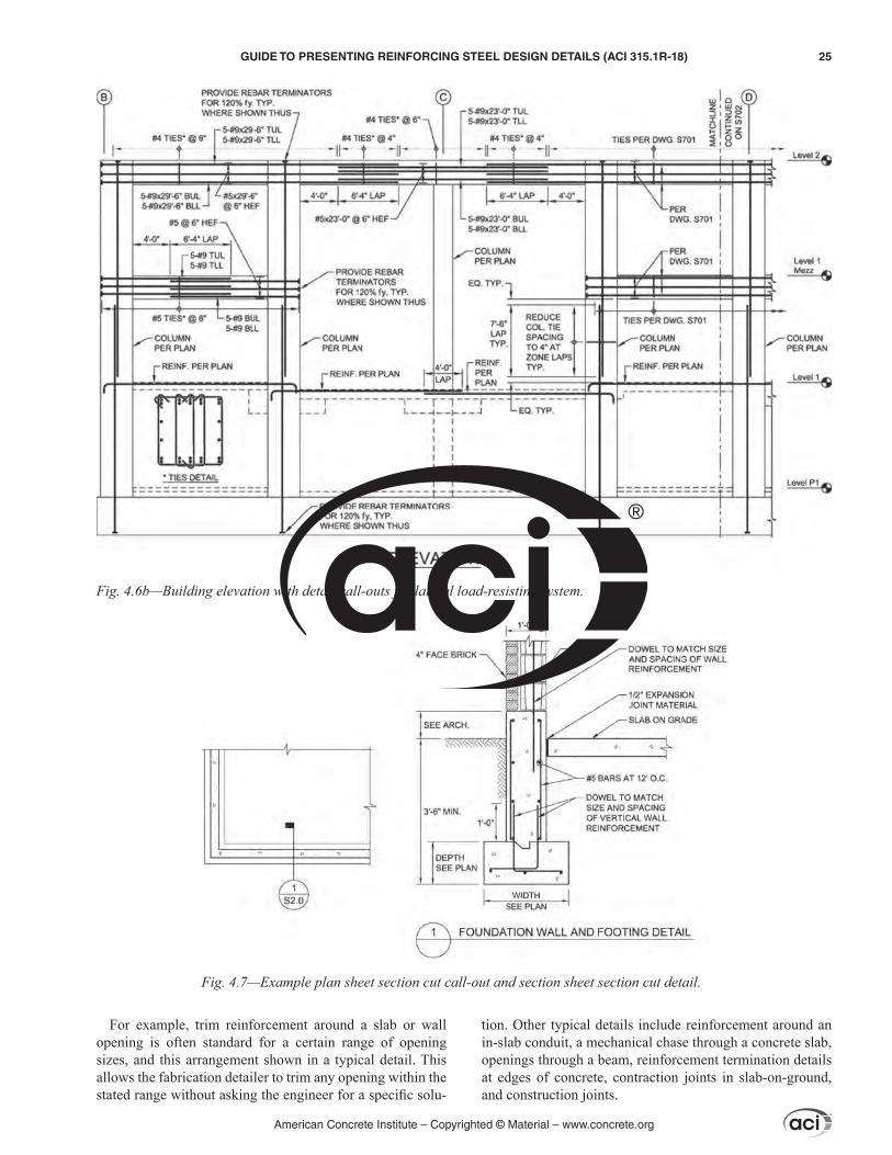
For example, trim reinforcement around a slab or wall opening is often standard for a certain range of opening sizes, and this arrangement shown in a typical detail. This allows the fabrication detailer to trim any opening within the stated range without asking the engineer for a specific solu-
tion. Other typical details include reinforcement around an in-slab conduit, a mechanical chase through a concrete slab, openings through a beam, reinforcement termination details at edges of concrete, contraction joints in slab-on-ground, and construction joints.
Fig. 4.6b—Building elevation with detail call-outs for lateral load-resisting system.
Fig. 4.7—Example plan sheet section cut call-out and section sheet section cut detail.
American Concrete Institute – Copyrighted © Material – www.concrete.org
GUIDE TO PRESENTING REINFORCING STEEL DESIGN DETAILS (ACI 315.1R-18) 25
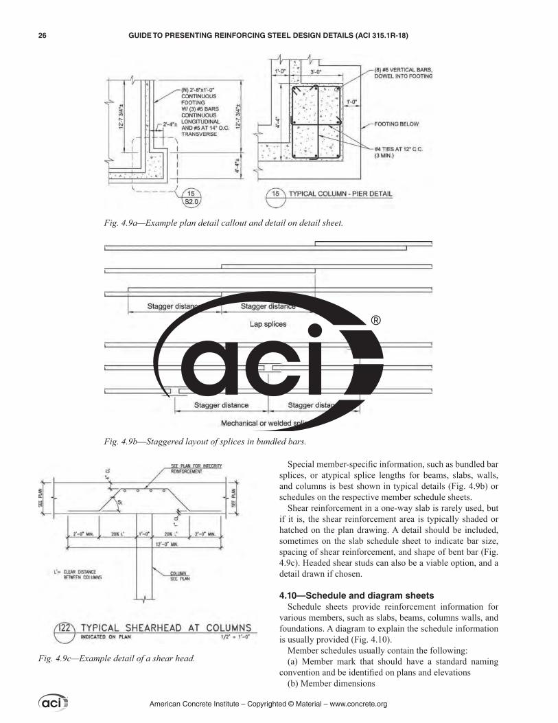
Special member-specific information, such as bundled bar splices, or atypical splice lengths for beams, slabs, walls, and columns is best shown in typical details (Fig. 4.9b) or schedules on the respective member schedule sheets.
Shear reinforcement in a one-way slab is rarely used, but if it is, the shear reinforcement area is typically shaded or hatched on the plan drawing. A detail should be included, sometimes on the slab schedule sheet to indicate bar size, spacing of shear reinforcement, and shape of bent bar (Fig. 4.9c). Headed shear studs can also be a viable option, and a detail drawn if chosen.
4.10—Schedule and diagram sheetsSchedule sheets provide reinforcement information for
various members, such as slabs, beams, columns walls, and foundations. A diagram to explain the schedule information is usually provided (Fig. 4.10).
Member schedules usually contain the following:(a) Member mark that should have a standard naming
convention and be identified on plans and elevations(b) Member dimensions
Fig. 4.9a—Example plan detail callout and detail on detail sheet.
Fig. 4.9b––Staggered layout of splices in bundled bars.
Fig. 4.9c—Example detail of a shear head.
American Concrete Institute – Copyrighted © Material – www.concrete.org
26 GUIDE TO PRESENTING REINFORCING STEEL DESIGN DETAILS (ACI 315.1R-18)

(c) Member reinforcement(d) Remarks or notes describing to include atypical rein-
forcement patterns, elevation, and concrete strength4.10.1 Slab schedulesSlab schedules usually contain the slab mark, thickness
of slab, bottom and top reinforcement, and any notes or remarks necessary for that slab.
If the LDP choses to terminate some of the reinforcement short of the support in one-way slabs, it should be indicated in a detail similar to Fig. 4.10.1a.
Two-way slabs supported by edge walls or by edge-beams require reinforcement in the top and bottom of the slab at the intersection of the two-way slab and edge members. This reinforcement is shown using typical details if it occurs throughout the structure, or the information is shown right on the plan drawings if it is not a prevalent detail. Refer to Fig. 4.10.1b for an example.
Two-way slab structural integrity reinforcement require-ments can be shown in different ways. The splicing require-ments for structural integrity reinforcement can be shown on the slab schedule diagram. The requirement of two column strip bottom bars or wires that are required to go through the columns can also be shown on the plan or in a typical detail. The typical detail option is probably used most often because other information can be shown on the same detail if the designer wishes. Refer to Fig. 4.10.1c for an example.
Two-way shear reinforcement in slabs could be headed shear studs, typical stirrups, or structural steel members. Headed shear studs are used most often; a detail should be drawn to show the layout of the headed shear studs, espe-cially at a column. When several different layouts of headed shear studs are needed in a structure, it may be clearer to use a series of headed shear stud diagrams, possibly in a table, to show their layouts as they vary throughout the structure
(Fig. 4.10.1d). The plan drawings should be marked at each column to indicate which headed shear stud diagram should be used at that location.
While stirrups are not used as regularly as headed shear studs for two-way shear reinforcement, they are permitted by the ACI 318 Code. When stirrups are used for two-way shear reinforcement, they can be shown on a schedule similar to the schedule for headed shear studs (Fig. 4.10.1e). Structural steel members are rarely used; however, if they are used their locations should be identified and special details provided.
4.10.2 Beam and girder schedules—Beams and girders are often shown in the same schedule and the information presented is similar. For simplicity of wording, the terms “beam” and “beam schedule” will be used here to include both. Beam schedules contain the beam mark, beam width and depth, top and bottom reinforcement and extent, post-tensioning reinforcement when applicable, and stirrup size, and spacing (Fig. 4.10.2).
Along with the beam schedule, there should be a diagram to show the basic layout of the reinforcing steel in a beam. For clarity, this often requires two diagrams with one showing the longitudinal reinforcing steel and the other showing the shear reinforcing steel. The diagrams are often
Fig. 4.10—Diagram provided to explain schedule information.
Fig. 4.10.1a—Example reinforcement terminations for a one-way slab.
American Concrete Institute – Copyrighted © Material – www.concrete.org
GUIDE TO PRESENTING REINFORCING STEEL DESIGN DETAILS (ACI 315.1R-18) 27

split into the following different types of beams: single span, multiple spans, and cantilever.
When applicable, the post-tensioning is typically speci-fied using the assumed effective force that is expected to be applied to the beam, or using the number of tendons from the design. Typical shear reinforcing stirrup sizes and spacing are shown in the schedule by specifying each group of stirrups. For example, a beam might need six No. 4 (No.13) stirrups at 2 in. (50 mm) o.c., and then six No. 4 (No. 13) stirrups at 6 in.
(150 mm) o.c. at each beam end, and the remainder along the length of the beam at 12 in. (300 mm) o.c.
Often, this type of shear reinforcement spacing at the ends of the beams or at other special shear reinforcing locations is shown in a typical diagram on the beam schedule sheet. The design drawings should provide a detail of stirrups showing the stirrup shape.
4.10.3 Column schedules—Column schedules usually contain the column mark, vertical reinforcement, and the
Fig. 4.10.1b—Termination rules for a two-way slab.
American Concrete Institute – Copyrighted © Material – www.concrete.org
28 GUIDE TO PRESENTING REINFORCING STEEL DESIGN DETAILS (ACI 315.1R-18)
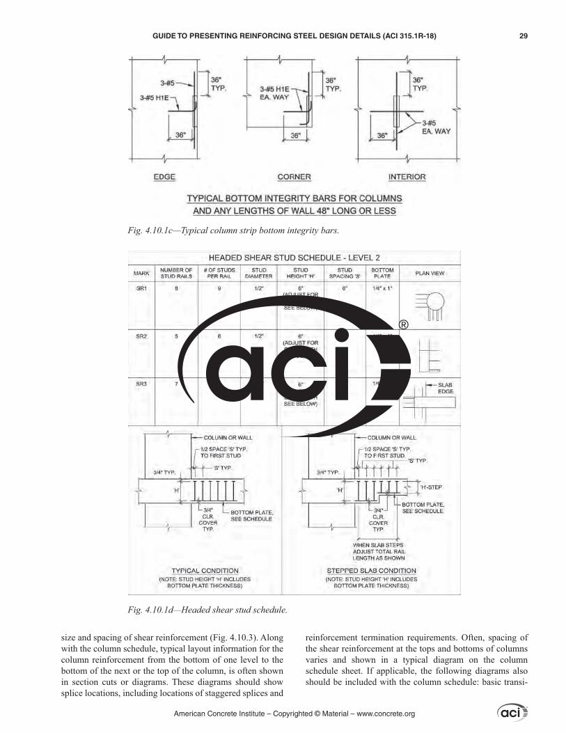
size and spacing of shear reinforcement (Fig. 4.10.3). Along with the column schedule, typical layout information for the column reinforcement from the bottom of one level to the bottom of the next or the top of the column, is often shown in section cuts or diagrams. These diagrams should show splice locations, including locations of staggered splices and
reinforcement termination requirements. Often, spacing of the shear reinforcement at the tops and bottoms of columns varies and shown in a typical diagram on the column schedule sheet. If applicable, the following diagrams also should be included with the column schedule: basic transi-
Fig. 4.10.1c—Typical column strip bottom integrity bars.
Fig. 4.10.1d—Headed shear stud schedule.
American Concrete Institute – Copyrighted © Material – www.concrete.org
GUIDE TO PRESENTING REINFORCING STEEL DESIGN DETAILS (ACI 315.1R-18) 29

tion from floor-to-floor, offset transitions, sloped transitions, and top of column terminations.
4.10.4 Wall schedules—Wall schedules usually contain the wall mark and amount of vertical and horizontal rein-forcement for each curtain of reinforcement required.
Along with the wall schedule, typically there will be a diagram of the wall from the bottom of the wall to the top of the wall, sometimes with section cuts showing the layout information for the wall reinforcement. These diagrams should show splice locations, including locations of stag-gered splices if necessary. Placing location of the rein-
Fig. 4.10.1e—Shear stirrup schedule.
Fig. 4.10.2—Example grade beam schedule.
American Concrete Institute – Copyrighted © Material – www.concrete.org
30 GUIDE TO PRESENTING REINFORCING STEEL DESIGN DETAILS (ACI 315.1R-18)
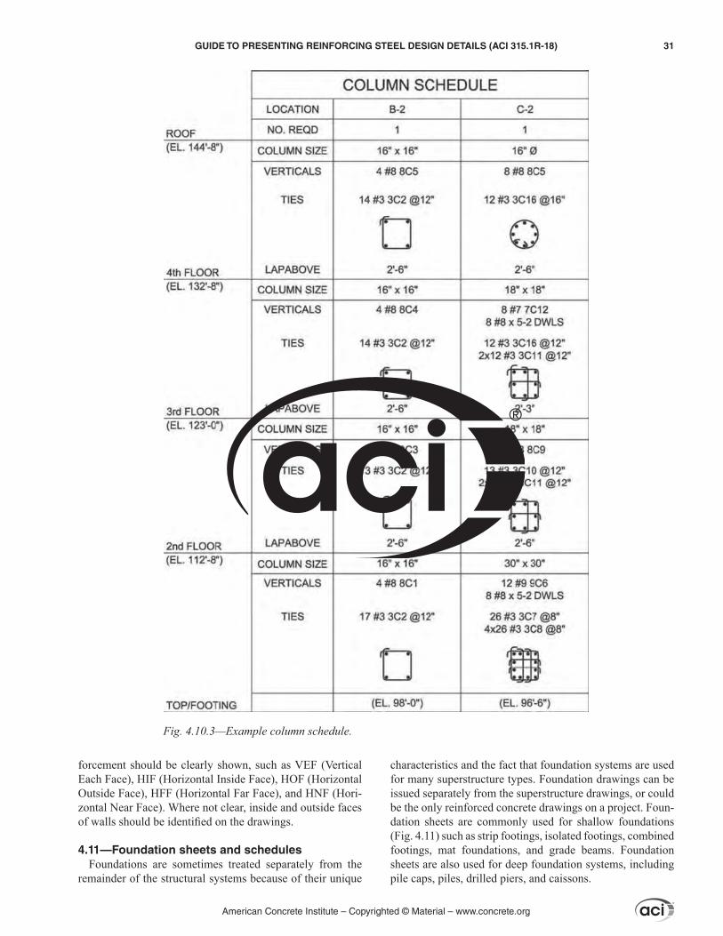
forcement should be clearly shown, such as VEF (Vertical Each Face), HIF (Horizontal Inside Face), HOF (Horizontal Outside Face), HFF (Horizontal Far Face), and HNF (Hori-zontal Near Face). Where not clear, inside and outside faces of walls should be identified on the drawings.
4.11—Foundation sheets and schedulesFoundations are sometimes treated separately from the
remainder of the structural systems because of their unique
characteristics and the fact that foundation systems are used for many superstructure types. Foundation drawings can be issued separately from the superstructure drawings, or could be the only reinforced concrete drawings on a project. Foun-dation sheets are commonly used for shallow foundations (Fig. 4.11) such as strip footings, isolated footings, combined footings, mat foundations, and grade beams. Foundation sheets are also used for deep foundation systems, including pile caps, piles, drilled piers, and caissons.
Fig. 4.10.3—Example column schedule.
American Concrete Institute – Copyrighted © Material – www.concrete.org
GUIDE TO PRESENTING REINFORCING STEEL DESIGN DETAILS (ACI 315.1R-18) 31

Foundation drawings can show foundation members with the reinforcement individually indicated or shown in a schedule. In a schedule, the member is identified by a letter or letters and a number. For example, P1 is usually related to a pile cap, F1 to a shallow footing, and GB1 to a grade beam. An Abbreviation and Notation Legend should always be included in the drawing sheet for clarity and ease of identification. Grade beam schedules are similar to elevated beam schedules; guidelines regarding beam schedules are shown in 4.10.2. Pile cap schedules should include dimen-sions of the pile cap and the required reinforcement in each one. Footing schedules are usually similar, with the schedule containing footing dimensions and the required reinforce-ment in each direction. Drilled piers are often not sched-uled by mark, but by shaft and bell diameters. The schedule should include a listing of vertical reinforcement, tie rein-forcement, and minimum distance that the reinforcement should extend into the top of the pier.
Each type of foundation element on the project should have a corresponding typical diagram that is referenced from the schedule. This typical diagram will show a typical layout of the member with typical locations of the reinforcement inside of it.
Although shear reinforcement in a foundation is not frequently used, when it is used, the design detail is presented in a manner similar to a beam. When stirrups are used for shear reinforcement, they should be shown on the founda-tion schedule and a separate detail or section considered.
4.12—User-defined sheetsUser-defined sheets show information that is not presented
on other sheets.
4.13—Three-dimensional representationsAlthough three-dimensional representations or isometric
sketches are not commonly used, they can be helpful to show an especially complicated connection or joint, or to coordinate among different disciplines to prevent clashes among different systems
CHAPTER 5—DESIGNING FOR CONSTRUCTABILITY
Reinforcing steel design and detailing should conform to ACI 318-14. Minimum spacing of reinforcement should be in accordance with Section 25.2. Standard hook geometry should be in accordance with Section 25.3. Development lengths and splices of deformed reinforcement should be in accordance with Sections 25.4 and 25.5 respectively.
Code requirements often refer to minimum or maximum values. Good design practice should generally strive to avoid the indiscriminate use of minimum code values without considering constructability. For example, avoid or reduce constructability issues due to interference between overcrowding of steel reinforcement and loss of concrete cover or spacing problems between reinforcing bars due to incremental tolerance buildup. The licensed design profes-sional (LDP) should render the design clearly. Clarity will assist the detailer and contractor in correctly interpreting the
Fig. 4.11—Foundation plan drawing.
American Concrete Institute – Copyrighted © Material – www.concrete.org
32 GUIDE TO PRESENTING REINFORCING STEEL DESIGN DETAILS (ACI 315.1R-18)
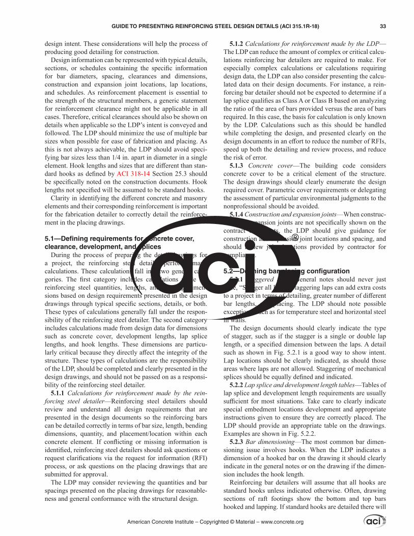
design intent. These considerations will help the process of producing good detailing for construction.
Design information can be represented with typical details, sections, or schedules containing the specific information for bar diameters, spacing, clearances and dimensions, construction and expansion joint locations, lap locations, and schedules. As reinforcement placement is essential to the strength of the structural members, a generic statement for reinforcement clearance might not be applicable in all cases. Therefore, critical clearances should also be shown on details when applicable so the LDP’s intent is conveyed and followed. The LDP should minimize the use of multiple bar sizes when possible for ease of fabrication and placing. As this is not always achievable, the LDP should avoid speci-fying bar sizes less than 1/4 in. apart in diameter in a single element. Hook lengths and sizes that are different than stan-dard hooks as defined by ACI 318-14 Section 25.3 should be specifically noted on the construction documents. Hook lengths not specified will be assumed to be standard hooks.
Clarity in identifying the different concrete and masonry elements and their corresponding reinforcement is important for the fabrication detailer to correctly detail the reinforce-ment in the placing drawings.
5.1—Defining requirements for concrete cover, clearance, development, and splices
During the process of preparing the detail drawings for a project, the reinforcing steel detailer performs many calculations. These calculations fall into two general cate-gories. The first category includes calculations made for reinforcing steel quantities, lengths, and bending dimen-sions based on design requirements presented in the design drawings through typical specific sections, details, or both. These types of calculations generally fall under the respon-sibility of the reinforcing steel detailer. The second category includes calculations made from design data for dimensions such as concrete cover, development lengths, lap splice lengths, and hook lengths. These dimensions are particu-larly critical because they directly affect the integrity of the structure. These types of calculations are the responsibility of the LDP, should be completed and clearly presented in the design drawings, and should not be passed on as a responsi-bility of the reinforcing steel detailer.
5.1.1 Calculations for reinforcement made by the rein-forcing steel detailer—Reinforcing steel detailers should review and understand all design requirements that are presented in the design documents so the reinforcing bars can be detailed correctly in terms of bar size, length, bending dimensions, quantity, and placement/location within each concrete element. If conflicting or missing information is identified, reinforcing steel detailers should ask questions or request clarifications via the request for information (RFI) process, or ask questions on the placing drawings that are submitted for approval.
The LDP may consider reviewing the quantities and bar spacings presented on the placing drawings for reasonable-ness and general conformance with the structural design.
5.1.2 Calculations for reinforcement made by the LDP—The LDP can reduce the amount of complex or critical calcu-lations reinforcing bar detailers are required to make. For especially complex calculations or calculations requiring design data, the LDP can also consider presenting the calcu-lated data on their design documents. For instance, a rein-forcing bar detailer should not be expected to determine if a lap splice qualifies as Class A or Class B based on analyzing the ratio of the area of bars provided versus the area of bars required. In this case, the basis for calculation is only known by the LDP. Calculations such as this should be handled while completing the design, and presented clearly on the design documents in an effort to reduce the number of RFIs, speed up both the detailing and review process, and reduce the risk of error.
5.1.3 Concrete cover—The building code considers concrete cover to be a critical element of the structure. The design drawings should clearly enumerate the design required cover. Parametric cover requirements or delegating the assessment of particular environmental judgments to the nonprofessional should be avoided.
5.1.4 Construction and expansion joints—When construc-tion and expansion joints are not specifically shown on the contract documents, the LDP should give guidance for construction and expansion joint locations and spacing, and should review joint locations provided by contractor for compliance.
5.2—Defining bar placing configuration5.2.1 Staggered laps—General notes should never just
state, “Stagger all laps.” Staggering laps can add extra costs to a project in terms of detailing, greater number of different bar lengths, and placing. The LDP should note possible exceptions, such as for temperature steel and horizontal steel in walls.
The design documents should clearly indicate the type of stagger, such as if the stagger is a single or double lap length, or a specified dimension between the laps. A detail such as shown in Fig. 5.2.1 is a good way to show intent. Lap locations should be clearly indicated, as should those areas where laps are not allowed. Staggering of mechanical splices should be equally defined and indicated.
5.2.2 Lap splice and development length tables—Tables of lap splice and development length requirements are usually sufficient for most situations. Take care to clearly indicate special embedment locations development and appropriate instructions given to ensure they are correctly placed. The LDP should provide an appropriate table on the drawings. Examples are shown in Fig. 5.2.2.
5.2.3 Bar dimensioning—The most common bar dimen-sioning issue involves hooks. When the LDP indicates a dimension of a hooked bar on the drawing it should clearly indicate in the general notes or on the drawing if the dimen-sion includes the hook length.
Reinforcing bar detailers will assume that all hooks are standard hooks unless indicated otherwise. Often, drawing sections of raft footings show the bottom and top bars hooked and lapping. If standard hooks are detailed there will
American Concrete Institute – Copyrighted © Material – www.concrete.org
GUIDE TO PRESENTING REINFORCING STEEL DESIGN DETAILS (ACI 315.1R-18) 33

be no lap. The design drawings should clearly indicate if a lap is intended and if so, dimension the lap (Fig. 5.2.3).
Where standard hooks would be too long to fit within the concrete member, the desired hook should be clearly dimen-sioned on the drawing.
5.2.4 Skewed bars—In plan views of trapezoidal-shaped slabs, the LDP should clearly indicate if the main bars are perpendicular to the parallel sides or parallel to the sloped sides (Fig. 5.2.4). Also indicate if the spacing of the bars is measured at right angles to the main bars or along the skew. These points should also be made clear for triangular or other irregular-shaped slabs.
Top steel over beams in skewed slabs can conflict with top bars from adjacent regular-shaped slabs and could cause layering and clearance problems. These conditions should be considered and addressed by the LDP.
5.2.5 Termination of vertical bars—The design drawings should always indicate how vertical bars are to be termi-nated. If the bars are to be hooked, there are several consid-erations as follows:
(a) If the hook is not a standard hook, the length should be indicated
(b) If the hook is located in either of the top layers or beneath both layers
(c) If the member into which the hook is to be embedded is sufficiently deep enough to accommodate the curvature of the bend
(d) If the direction of the hook is critical, it should be clearly indicated.
If nothing is indicated, hook direction will not be noted on the shop drawings and will likely be placed based on other field constraints. Member intersections can require addi-tional consideration of bar interferences.
5.2.6 Beam stirrups—On a beam schedule, it should be clear whether a stirrup callout—for example, 3 @ 6 in.; 5 @ 9 in.; rem @ 12 in. (3 @ 150 mm; 5 @ 225 mm; rem @ 300 mm)—is referring to the number of stirrups or the number of spaces. If spacing of the first stirrup from a support is
critical, it should be indicated, otherwise it will be located one-half space from the face of support.
In multiple tie sets, indicate if these are to be a series of nested stirrups or a series of interlocking stirrups. If open stirrups are indicated, if possible, try to provide a continuous top bar in each stirrup hook. Consider a greater quantity of smaller longitudinal bars rather than fewer larger bars.
In very narrow beams, determine if the stirrup hooks will allow the top bars to fit within the tie. If critical, indicate if longitudinal bars are to be lapped in a vertical or hori-zontal plane. At intersecting beams, indicate if the stirrups run through one beam or the other, or through both beams.
5.3—FoundationsThis section applies to nonprestressed steel reinforcement
of shallow and deep structural foundations as defined by ACI 318-14 Chapter 13 and includes piles, drilled piers, and caissons as further discussed in ACI 336.3R and ACI 543R. Refer to Section 5.5 of ACI 543R-12 for the supplemental details of deep foundations in structures assigned to Seismic Design Categories D, E, and F as prescribed by ACI 318-14 Section 18.13.4.
5.3.1 Types—Generally, foundation systems are catego-rized as either shallow foundations or deep foundations. Shallow foundations include such types as strip footings; isolated, spread, or pad footings; mat foundations; and grade beams. Caps are typically shallow elements transferring load to deep foundations.
5.3.2 Bar arrangements—Bar arrangements vary widely based on both the foundation type and the lateral, gravity, and torsional loadings imposed on the foundations. The example reinforcing details described in this section are common arrangements. The LDP should specify appropriate bar arrangements for the various conditions.
Shallow foundations such as strip, isolated, and mat foun-dations often have a bar arrangement similar to that of a slab with a bottom mat, a top mat, or both bottom and top mat of reinforcement with bars in each direction. In some instances,
Fig. 5.2.1—Staggered lap splices and staggered mechanical splices.
American Concrete Institute – Copyrighted © Material – www.concrete.org
34 GUIDE TO PRESENTING REINFORCING STEEL DESIGN DETAILS (ACI 315.1R-18)

Fig 5.2.2—Development and lap splice table.
Fig. 5.2.3—Possible hook configurations at edge of raft footing.
Fig. 5.2.4—Skewed slab.
American Concrete Institute – Copyrighted © Material – www.concrete.org
GUIDE TO PRESENTING REINFORCING STEEL DESIGN DETAILS (ACI 315.1R-18) 35

the bars can be required to be hooked at ends for develop-ment as prescribed by the LDP.
Grade beams and tie beams sometime span between foun-dation elements such as pile caps. Grade beams usually project above grade to support walls; tie beams are usually below grade and spread lateral loads to multiple deep foun-dations. Grade beams and tie beams have two primary rein-forcement arrangements. The first is similar to a beam with reinforcing ties or stirrups, top and bottom longitudinal steel, and in some cases side longitudinal steel. The second arrangement is still similar to a beam; however, it might only have top and bottom reinforcement. Ties in the second arrangement may only be required for constructability as a method to support the top reinforcement.
Deep foundations are often round and have a bar arrange-ment similar to that of a round column with circular ties or a spiral around the perimeter and longitudinal steel spaced around the perimeter inside the tie. Smaller drilled piers might only have longitudinal steel that is centered in the drilled pier. In these cases, reinforcement can be added for constructability to keep the reinforcement centered in the shaft. Although reinforcement in piers is similar to that of columns, it is not fully prescribed by ACI 318 and, therefore, is often excluded from the ACI 318-14 Section 25.7.2.4.1 requirement for standard hooks at the ends of ties, except for the case of piers in Seismic Design Categories D, E, and F. Refer to Fig. 5.3.2 of this guide.
5.3.3 Bar supports—Special consideration should be given to mat foundations. Top steel support systems are commonly designed by the contractor, bar fabricator, or bar placer. Support systems for concrete foundations 4 ft (1.2 m) or more in depth should be approved by a licensed profes-sional engineer. The supports should carry the weight of the steel and the forces created by movement of the concrete crew and others walking on the top mat. Contractors can request the use of WWR for worker safety on slabs and mat foundations, if a foot could slip between bars and fall 2 ft or more. At times, workers may have to work between the bottom and top mats. Bottom reinforcement of elements cast against the earth is usually supported on concrete or concrete blocks known as “dobies.”
Support systems can vary from simple standees to elabo-rate structural frames. Design of the support system should consider that the support/top mat structure is not free-standing, but requires lateral support by the formwork. The
formwork for a thick mat foundation has been designed to withstand the lateral forces of a significant head of fresh concrete. While the vertical load of the top mat is signifi-cant, the lateral forces generated within the formwork are relatively small. Plastic or concrete spacers can secure the top mat against the formwork. The need for the formwork to restrain lateral movement of the support/top mat structure should be coordinated with the formwork engineer.
5.3.4 Layering—The direction of reinforcing steel layers in foundations primarily only applies to shallow founda-tions because grade beams are typically reinforced, similar to beams and deep foundations are typically reinforced similar to columns as noted in 5.3.2. For strip footings, the layering might be with transverse bars bottom-most for flex-ural strength, but for construction efficiency in placing rein-forcement, it is better to locate the longitudinal bars bottom-most. Isolated pad footing layering most often depends on the geometry of the pad footing. For square pad footings, layering can go either way. For rectangular pad footings, reinforcement along the larger dimension usually runs in the bottom and top outer layers, and the reinforcement along the shorter dimension runs inside of the outer layers. For thick mat foundations not supported by deep foundations, the layering will be similar to that of rectangular pad footings. The cases discussed previously are typical layering condi-tions for foundations; however, each is also dependent on the design of the foundation. Always refer to the contract documents for specific requirements. Contract documents should specifically note the layering arrangement when it is critical to the design.
All reinforcement layering should be properly supported to keep the reinforcement at the correct location in the element.
5.4—WallsACI 318-14 Section 2.3 defines a wall as “A vertical
element designed to resist axial load, lateral load, or both, with a horizontal length-to-thickness ratio greater than 3, used to enclose or separate spaces.” Concrete walls are structural elements that are generally used as vertical- and lateral-force-resisting members. Walls may be used in under-ground or aboveground tanks to contain liquids, as retaining walls, or for providing one-sided lateral confinement for soil or other materials, and for providing continuous support for floor or roof systems, in which case they should absorb and resist all reactions from these systems.
This section applies to steel reinforcement of nonpre-stressed ordinary structural walls, including: cast-in-place, precast in-plant and precast on-site, and tilt-up construction as defined in ACI 318-14 Chapter 11.
5.4.1 General—Steel reinforcement should be provided in walls to resist all in-plane and out-of-plane forces acting on ordinary structural walls, as shown in Fig. 5.4.1 of this guide (ACI 318-14 Chapter 11). Walls subjected to these forces will require longitudinal and transverse reinforcement, as well as additional reinforcement around openings. Design requirements are contained in ACI 318-14 Sections 11.3, 11.4 and 11.5.
Fig. 5.3.2—Pier tie arrangements.
American Concrete Institute – Copyrighted © Material – www.concrete.org
36 GUIDE TO PRESENTING REINFORCING STEEL DESIGN DETAILS (ACI 315.1R-18)
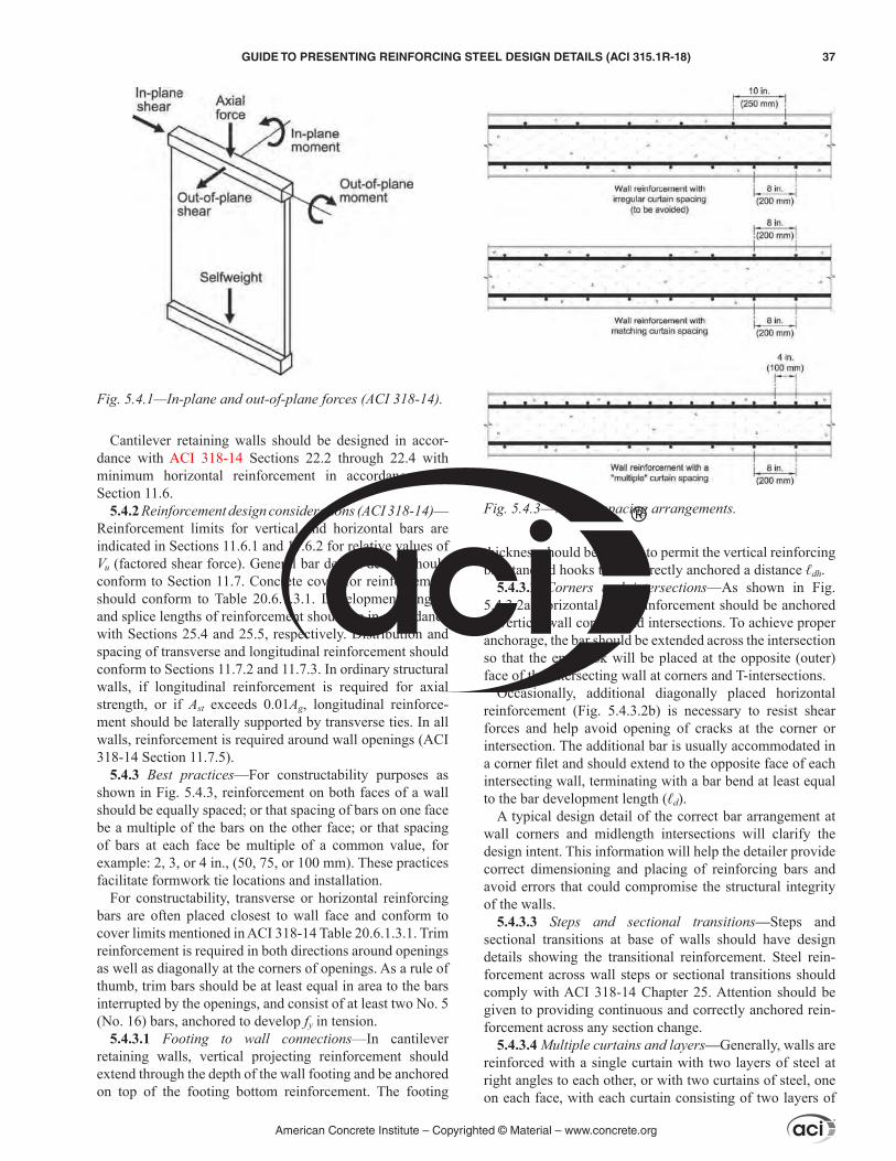
Cantilever retaining walls should be designed in accor-dance with ACI 318-14 Sections 22.2 through 22.4 with minimum horizontal reinforcement in accordance with Section 11.6.
5.4.2 Reinforcement design considerations (ACI 318-14)—Reinforcement limits for vertical and horizontal bars are indicated in Sections 11.6.1 and 11.6.2 for relative values of Vu (factored shear force). General bar design details should conform to Section 11.7. Concrete cover for reinforcement should conform to Table 20.6.1.3.1. Development lengths and splice lengths of reinforcement should be in accordance with Sections 25.4 and 25.5, respectively. Distribution and spacing of transverse and longitudinal reinforcement should conform to Sections 11.7.2 and 11.7.3. In ordinary structural walls, if longitudinal reinforcement is required for axial strength, or if Ast exceeds 0.01Ag, longitudinal reinforce-ment should be laterally supported by transverse ties. In all walls, reinforcement is required around wall openings (ACI 318-14 Section 11.7.5).
5.4.3 Best practices—For constructability purposes as shown in Fig. 5.4.3, reinforcement on both faces of a wall should be equally spaced; or that spacing of bars on one face be a multiple of the bars on the other face; or that spacing of bars at each face be multiple of a common value, for example: 2, 3, or 4 in., (50, 75, or 100 mm). These practices facilitate formwork tie locations and installation.
For constructability, transverse or horizontal reinforcing bars are often placed closest to wall face and conform to cover limits mentioned in ACI 318-14 Table 20.6.1.3.1. Trim reinforcement is required in both directions around openings as well as diagonally at the corners of openings. As a rule of thumb, trim bars should be at least equal in area to the bars interrupted by the openings, and consist of at least two No. 5 (No. 16) bars, anchored to develop fy in tension.
5.4.3.1 Footing to wall connections—In cantilever retaining walls, vertical projecting reinforcement should extend through the depth of the wall footing and be anchored on top of the footing bottom reinforcement. The footing
thickness should be such as to permit the vertical reinforcing bar standard hooks to be correctly anchored a distance ℓdh.
5.4.3.2 Corners and intersections—As shown in Fig. 5.4.3.2a, horizontal wall reinforcement should be anchored in vertical wall corners and intersections. To achieve proper anchorage, the bar should be extended across the intersection so that the end hook will be placed at the opposite (outer) face of the intersecting wall at corners and T-intersections.
Occasionally, additional diagonally placed horizontal reinforcement (Fig. 5.4.3.2b) is necessary to resist shear forces and help avoid opening of cracks at the corner or intersection. The additional bar is usually accommodated in a corner filet and should extend to the opposite face of each intersecting wall, terminating with a bar bend at least equal to the bar development length (ℓd).
A typical design detail of the correct bar arrangement at wall corners and midlength intersections will clarify the design intent. This information will help the detailer provide correct dimensioning and placing of reinforcing bars and avoid errors that could compromise the structural integrity of the walls.
5.4.3.3 Steps and sectional transitions—Steps and sectional transitions at base of walls should have design details showing the transitional reinforcement. Steel rein-forcement across wall steps or sectional transitions should comply with ACI 318-14 Chapter 25. Attention should be given to providing continuous and correctly anchored rein-forcement across any section change.
5.4.3.4 Multiple curtains and layers—Generally, walls are reinforced with a single curtain with two layers of steel at right angles to each other, or with two curtains of steel, one on each face, with each curtain consisting of two layers of
Fig. 5.4.1—In-plane and out-of-plane forces (ACI 318-14).
Fig. 5.4.3—Various spacing arrangements.
American Concrete Institute – Copyrighted © Material – www.concrete.org
GUIDE TO PRESENTING REINFORCING STEEL DESIGN DETAILS (ACI 315.1R-18) 37
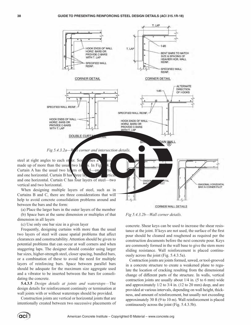
steel at right angles to each other. Sometimes a curtain is made up of more than the usual two layers. In Fig. 5.4.3.4, Curtain A has the usual two layers of steel—one vertical, and one horizontal. Curtain B has three layers—two vertical and one horizontal. Curtain C has four layers of steel—two vertical and two horizontal.
When designing multiple layers of steel, such as in Curtains B and C, there are three considerations that will help to avoid concrete consolidation problems around and between the bars and the form:
(a) Place the larger bars in the outer layers of the member(b) Space bars at the same dimension or multiples of that
dimension in all layers(c) Use only one bar size in a given layerFrequently, designing curtains with more than the usual
two layers of steel will cause spatial problems that affect clearances and constructability. Attention should be given to potential problems that can occur at wall corners and when staggering laps. The designer should consider using larger bar sizes, higher-strength steel, closer spacing, bundled bars, or a combination of these to avoid the need for multiple layers of reinforcing bars. Space between parallel bars should be adequate for the maximum size aggregate used and a vibrator to be inserted between the bars for consoli-dating the concrete.
5.4.3.5 Design details at joints and waterstops—The design details for reinforcement continuity or termination at wall joints with or without waterstops should be provided.
Construction joints are vertical or horizontal joints that are intentionally created between two successive placements of
concrete. Shear keys can be used to increase the shear resis-tance at the joint. If keys are not used, the surface of the first pour should be cleaned and roughened as required per the construction documents before the next concrete pour. Keys are commonly formed in the wall base to give the stem more sliding resistance. Wall reinforcement is placed continu-ously across the joint (Fig. 5.4.3.5a).
Contraction joints are joints formed, sawed, or tool-grooved in a concrete structure to create a weakened plane to regu-late the location of cracking resulting from the dimensional change of different parts of the structure. In walls, vertical contraction joints are usually about 1/4 in. (5 to 6 mm) wide and approximately 1/2 to 3/4 in. (12 to 20 mm) deep, and are provided at various intervals, depending on wall height, thick-ness, and amount of reinforcement, but usually not exceeding approximately 30 ft (9 to 10 m). Wall reinforcement is placed continuously across the joint (Fig. 5.4.3.5b).
Fig 5.4.3.2a—Wall corner and intersection details.
Fig 5.4.3.2b—Wall corner details.
American Concrete Institute – Copyrighted © Material – www.concrete.org
38 GUIDE TO PRESENTING REINFORCING STEEL DESIGN DETAILS (ACI 315.1R-18)
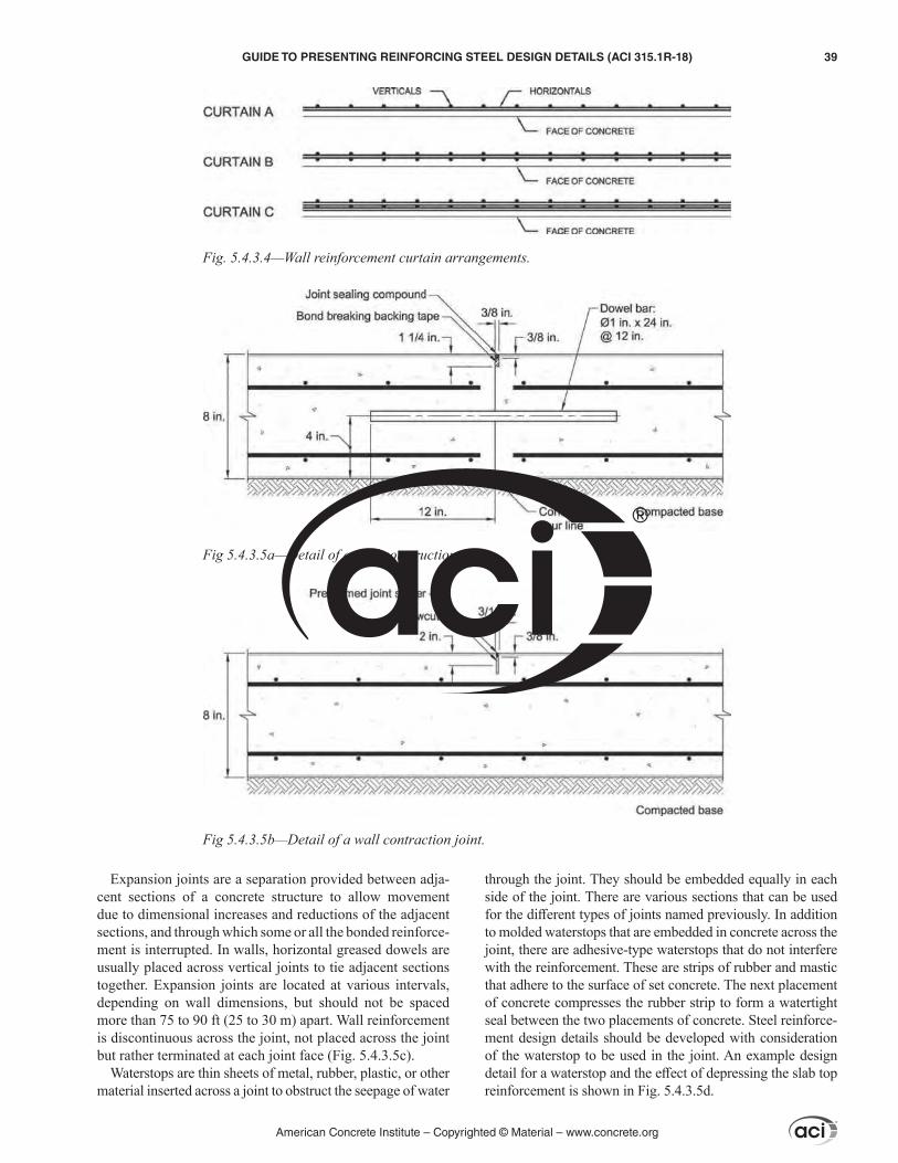
Expansion joints are a separation provided between adja-cent sections of a concrete structure to allow movement due to dimensional increases and reductions of the adjacent sections, and through which some or all the bonded reinforce-ment is interrupted. In walls, horizontal greased dowels are usually placed across vertical joints to tie adjacent sections together. Expansion joints are located at various intervals, depending on wall dimensions, but should not be spaced more than 75 to 90 ft (25 to 30 m) apart. Wall reinforcement is discontinuous across the joint, not placed across the joint but rather terminated at each joint face (Fig. 5.4.3.5c).
Waterstops are thin sheets of metal, rubber, plastic, or other material inserted across a joint to obstruct the seepage of water
through the joint. They should be embedded equally in each side of the joint. There are various sections that can be used for the different types of joints named previously. In addition to molded waterstops that are embedded in concrete across the joint, there are adhesive-type waterstops that do not interfere with the reinforcement. These are strips of rubber and mastic that adhere to the surface of set concrete. The next placement of concrete compresses the rubber strip to form a watertight seal between the two placements of concrete. Steel reinforce-ment design details should be developed with consideration of the waterstop to be used in the joint. An example design detail for a waterstop and the effect of depressing the slab top reinforcement is shown in Fig. 5.4.3.5d.
Fig. 5.4.3.4—Wall reinforcement curtain arrangements.
Fig 5.4.3.5a—Detail of a wall construction joint.
Fig 5.4.3.5b—Detail of a wall contraction joint.
American Concrete Institute – Copyrighted © Material – www.concrete.org
GUIDE TO PRESENTING REINFORCING STEEL DESIGN DETAILS (ACI 315.1R-18) 39

5.5—ColumnsThis section applies to steel reinforcement of nonpre-
stressed structural columns as defined by ACI 318-14 Chapter 10, and portions of deep foundations described by ACI 318-14 Section 13.4.3.1, as portions of deep founda-tion members in air, water, or soils not capable of providing adequate restraint throughout the member length to prevent lateral buckling.
5.5.1 Vertical bar arrangement—Vertical bar arrange-ment is prescribed by ACI 318-14 Section 10.7.3, requiring a minimum of three vertical bars with a triangular tie, four vertical bars within rectangular and circular ties, and six vertical bars enclosed by spiral ties or for columns in special moment frames enclosed by circular ties. Vertical reinforce-ment is most commonly arranged equally spaced around the perimeter of the column and enclosed by tie reinforcement, and includes at least a vertical bar in each corner of noncir-cular columns.
The LDP should provide clear tie arrangements for various numbers of longitudinal bars in a member (Fig 5.5.1).
5.5.2 Ties—Tie reinforcement is prescribed by ACI 318 Sections 10.7.6 and 25.7.2. As noted in ACI 318-14 Section 25.7.2, ties are required to have a minimum clear spacing of four-thirds the nominal maximum coarse aggregate size and a maximum of the lesser of 16 longitudinal bar diam-eters, 48 tie bar diameters, and the smallest dimension of the column. Spirals are required to be spaced continuously with the clear spacing being at least the greater of 1 in. (25 mm) and four-thirds the nominal maximum coarse aggregate size and a maximum of 3 in. (75 mm).
The smallest tie size should be No. 3 (No. 10) for longitu-dinal bars No. 10 (No. 32) and smaller, and No. 4 (No. 13) for ties enclosing No. 11 (No. 36) bars and larger. Alterna-tively, typical tie reinforcement can be replaced by welded wire reinforcement (WWR) of an equivalent area, except for spiral ties and special seismic systems. Deformed wire can be used for spiral ties. For rectangular ties, the tie arrange-ment should provide lateral support for every corner and alternate longitudinal bar with 135-degree hook. Additional tie reinforcement is required to provide lateral support for every longitudinal bar enclosed by a rectangular tie when the clear spacing between laterally supported longitudinal bars exceeds 6 in. (150 mm) on each side. Circular tie reinforce-ment should lap by a minimum of 6 in. (150 mm), terminate with standard hooks at each end that enclose a longitudinal bar, and be staggered around the perimeter.
Per ACI 318-14 Section 10.7.6, at member ends or transi-tions, the bottom tie is to be located, at most, one-half the tie spacing above the top of footing or slab. The top tie should also not be located more than one-half the tie or spacing below the lowest horizontal reinforcement in the slab, drop panel, or shear cap above. In the case of beams or brackets framing into all sides of a column, the top tie is to be located within 3 in. (75 mm) below the lowest horizontal reinforce-ment in the shallowest beam or bracket. For spiral reinforce-ment, the bottom of the spiral should be located at the top of the footing or slab, with the top conforming to ACI 318-14 Table 10.7.6.3.2.
5.5.3 Detail at steps and transitions—At steps and transi-tions (Fig. 5.5.3), the vertical reinforcement often is detailed with an offset bend, covered in ACI 318-14 Section 10.7.4. The slope of this transition should not exceed one (H) to six
Fig 5.4.3.5c—Detail of a wall expansion joint.
Fig 5.4.3.5d—Detail of wall-to-slab joint with waterstop.
American Concrete Institute – Copyrighted © Material – www.concrete.org
40 GUIDE TO PRESENTING REINFORCING STEEL DESIGN DETAILS (ACI 315.1R-18)
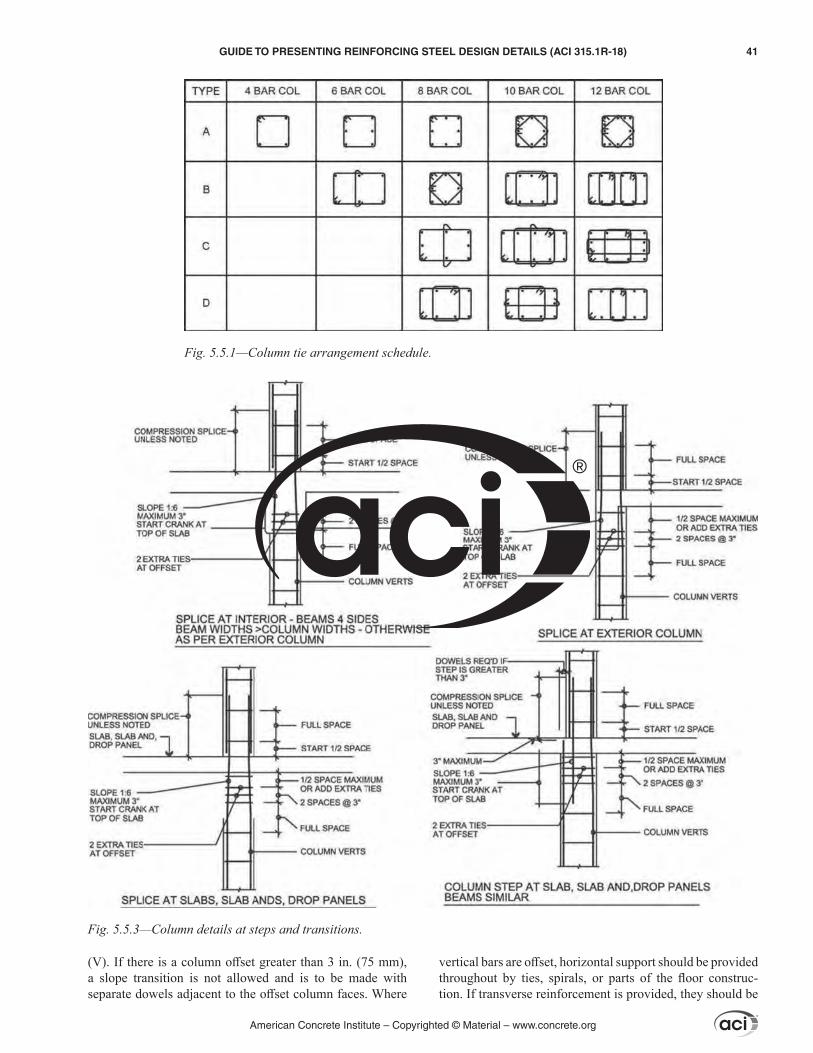
(V). If there is a column offset greater than 3 in. (75 mm), a slope transition is not allowed and is to be made with separate dowels adjacent to the offset column faces. Where
vertical bars are offset, horizontal support should be provided throughout by ties, spirals, or parts of the floor construc-tion. If transverse reinforcement is provided, they should be
Fig. 5.5.1—Column tie arrangement schedule.
Fig. 5.5.3—Column details at steps and transitions.
American Concrete Institute – Copyrighted © Material – www.concrete.org
GUIDE TO PRESENTING REINFORCING STEEL DESIGN DETAILS (ACI 315.1R-18) 41

placed no more than 6 in. (150 mm) from the points of the bend per ACI 318-14 Section 10.7.6.4. Offset bend locations should be specified by the LDP as appropriate. If not noted, the offset bends will be located based on ease of construction and contractor preference.
5.5.4 Laps—Column reinforcement lap lengths should be specifically indicated in the design drawings. Guidance should be given through schedules, notes, or other methods to accurately prescribe lap requirements per column. Gener-ally, compression laps can be allowed in gravity columns. These splices lengths can be factored by 0.83 when the effec-tive area of tie reinforcement through the lap zone meets the requirements of ACI 318, 10.7.5.2.1(a), or can be factored by 0.75 when spiral reinforcement is provided in accordance to ACI 318-14 Section 25.7.3. Attention should be given to areas of laps due to congestion.
Spiral reinforcement laps are dictated by ACI 318-14 Table 25.7.3.6, where the most common lap length is 48-bar diameters. Spiral reinforcement is required to be anchored by 1-1/2 extra turns of the spiral bar per ACI 318-14 Section 25.7.3.4.
5.5.5 Termination of vertical bars—Termination of vertical column reinforcement into beams and slabs is prescribed by ACI 318-14 Chapter 15. Termination of vertical column reinforcement into foundations is prescribed by ACI 318-14 Section 16.3. In heavily congested areas, headed bars are an effective alternate to hooks.
Termination of vertical bars in round columns requires special consideration (Fig. 5.5.5). Many round columns are formed with laminated paper fiber tubes. If the column vertical bars are terminated with hooks, the tube form cannot be slipped down over the erected column, nor can the column
reinforcement be installed if the tube is put in place first. The LDP should consider, if not subject to seismic provi-sions in ACI 318-14 Chapter 18, designing the termination with hooked bars spliced to the vertical bars after the tube form is in place.
5.6—BeamsThis section applies to steel reinforcement of nonpre-
stressed beams, as defined in ACI 318-14 Section 9.1.1. General reinforcing bar design details should conform to ACI 318-14 Sections 9.6 and 9.7. Bundled bars should be in accordance with ACI 318-14 Section 25.6. Develop-ment lengths and splices of deformed reinforcement should be in accordance with ACI 318 Sections 25.4 and 25.5, respectively.
5.6.1 Layering of beam bars at intersections—ACI 318-14 Sections 15.2 and 15.4 provide requirements for steel rein-forcement at beam-column joints. Longitudinal beam rein-forcement in beam-to-beam connections should be designed in such a way that the secondary beam’s top and bottom layers will be contained within the primary beam’s top and bottom longitudinal layers. Consideration should be given to intersecting beam depth dimensions and concrete cover for each of the intersecting members. Attention should be given to ACI 318 Sections 9.7 and 25.4.
5.6.2 Depth of beams at intersections—Generally, primary beams will be dimensioned for greater loads than secondary intersecting beams and, thus, will normally be larger in both width and depth. Dimensioning different depths for members in beam-to-beam and beam-to-girder connections will facilitate passage of longitudinal reinforcing bar layers through the intersection without affecting specified concrete cover (Fig. 5.6.2). When dimensioning both beams to the same depth to facilitate formwork, the additional bottom soffit cover for the secondary beam should be defined to avoid interference.
5.6.3 Tie arrangements—ACI 318-14 Sections 25.7.1 and 25.7.2, respectively, provide requirements for stirrups and ties. Both should extend as close to the compression and tension surfaces of the member as cover requirements and proximity of other reinforcement permit, and are to be anchored at both ends. Stirrups can be used to resist shear and torsion forces in a beam member; they consist typically of deformed bars, deformed wires, or WWR either single leg or bent into L, U, or rectangular shapes, and located perpen-dicular to, or at an angle to, longitudinal reinforcement. Ties should consist of a closed loop of deformed bar with spacing in accordance with 25.7.2.1. Tie bar diameter should be at least No. 3 (No. 10) for enclosing bars No. 10 (No. 32) or smaller, and No. 4 (No. 13) for enclosing bars No. 11 (No. 36) or larger and bundled longitudinal bars. Rectilinear ties should be arranged to satisfy 25.7.2.3. Stirrups used for torsion or integrity reinforcement can be either closed stir-rups placed perpendicular to the beam axis, as specified in 25.7.1.6, or can be made up of two pieces of reinforcement when conditions in 25.7.1.6.1 are met.
For large beams with long spans and heavy reinforce-ment, closed ties may reduce constructability. The long bars
Fig. 5.5.5—Showing hooked bars spliced to vertical bars in a round column.
American Concrete Institute – Copyrighted © Material – www.concrete.org
42 GUIDE TO PRESENTING REINFORCING STEEL DESIGN DETAILS (ACI 315.1R-18)

should be threaded into the beams through column verticals and other obstructions. With open stirrups, the long bars are simply lifted and dropped into place without any threading required. Once the bars are installed, the stirrups can be capped as necessary.
If the LDP shows only the closed ties option on the design documents, the detailer will likely issue an RFI requesting a change of stirrup configuration to open/capped style (Fig. 5.6.3). This process may significantly delay the detailer, depending on turnaround time for RFIs. This is usually an unnecessary interruption; in most cases, the open/capped tie option is approved. Design documents that clearly show both options whenever open ties are acceptable speeds up the detailing process and reduces the document flow required by the designer, contractor, and detailer, and constructability is enhanced.
5.6.4 Arrangement of longitudinal bars—ACI 318 Chap-ters 9 and 25 provide requirements for longitudinal reinforce-ment in beams. Clear spacing between bars in a horizontal layer should be at least the greater of 1 in. (25 mm), 1.0db, and (4/3)dagg. For parallel nonprestressed reinforcement placed in two or more horizontal layers, reinforcement in the upper layers should be placed directly above reinforcement in the bottom layer with a clear spacing between layers of at least 1 in. (25 mm). Standard hooks for the development of deformed bars in tension should conform to ACI 318-14 Table 25.3.1. Reinforcement limits should be in accordance with ACI 318-14 Section 9.6. Attention should be given to
ACI 318-14 Section 9.7.2.3, for detailing skin reinforcement in beams with depth h exceeding 36 in. (900 mm). Design of longitudinal reinforcement should comply with ACI 318-14 Section 9.7.3. Requirements for structural integrity are contained in ACI 318-14 Section 9.7.7.
In general, especially with multi-leg tie arrangements, numerous continuous longitudinal top and bottom bars should be placed to occupy the necessary positions required for every corner or leg of the tie set; the remaining bars will be spaced across the remaining space, in one or more layers. This will permit secure fastening in position of the ties in their correct shear-resisting position as well as provide lateral confinement for the longitudinal bars.
5.6.5 Beam steps—ACI 318 Chapters 9 and 25 provide requirements for steel reinforcement across beam steps or along beam section changes. Attention should be given to bar anchorage, development lengths, and providing continuous and correctly anchored reinforcement across any section change (Fig. 5.6.5).
5.6.6 Special details—Where nontypical conditions for steel reinforcement in beams, either geometrical or for other reasons, cannot be fully and correctly represented by eleva-tions, sections, and schedules, specific design details should be presented for these conditions. The governing criteria should be to present clear and precise information for the detailer to help avoid misinterpretation of design drawings and delays in the detailing process.
5.6.7 Beam schedules—Beams with similar geometry and steel reinforcement distribution can be represented with typical details and a beam schedule (Fig. 5.6.7) containing the specific information for bar diameters and dimensions, development and cutoff lengths, continuity of structural integrity reinforcement, and other information. Clarity in identifying the different beams and their corresponding rein-forcement is important for the detailer to be able to correctly detail steel reinforcement in the placing drawings.
5.7—SlabsThis section applies to steel reinforcement of nonpre-
stressed slabs, as defined in ACI 318-14 Chapters 7 and 8, and ACI 421.1R-08.
5.7.1 Bottom and top reinforcement—Construction docu-ments should include the minimum cover from the bottom, sides, and top of concrete in sections and details.
ACI 318-14 Section 25.5 provides reinforcement design requirements for embedment. Drawings should include the minimum embedment lengths into beams, columns, pilas-ters, or other supporting elements. These lengths should be shown in details, sections, plans, or schedules.
Fig. 5.6.2—Primary beam–secondary beam connection.
Fig. 5.6.3—Possible options for a tie set with closed design.
American Concrete Institute – Copyrighted © Material – www.concrete.org
GUIDE TO PRESENTING REINFORCING STEEL DESIGN DETAILS (ACI 315.1R-18) 43
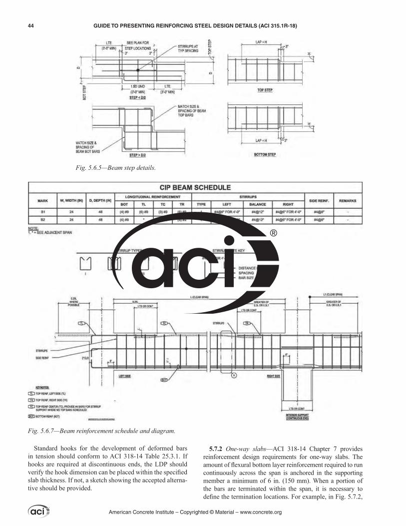
Standard hooks for the development of deformed bars in tension should conform to ACI 318-14 Table 25.3.1. If hooks are required at discontinuous ends, the LDP should verify the hook dimension can be placed within the specified slab thickness. If not, a sketch showing the accepted alterna-tive should be provided.
5.7.2 One-way slabs—ACI 318-14 Chapter 7 provides reinforcement design requirements for one-way slabs. The amount of flexural bottom layer reinforcement required to run continuously across the span is anchored in the supporting member a minimum of 6 in. (150 mm). When a portion of the bars are terminated within the span, it is necessary to define the termination locations. For example, in Fig. 5.7.2,
Fig. 5.6.5—Beam step details.
Fig. 5.6.7—Beam reinforcement schedule and diagram.
American Concrete Institute – Copyrighted © Material – www.concrete.org
44 GUIDE TO PRESENTING REINFORCING STEEL DESIGN DETAILS (ACI 315.1R-18)
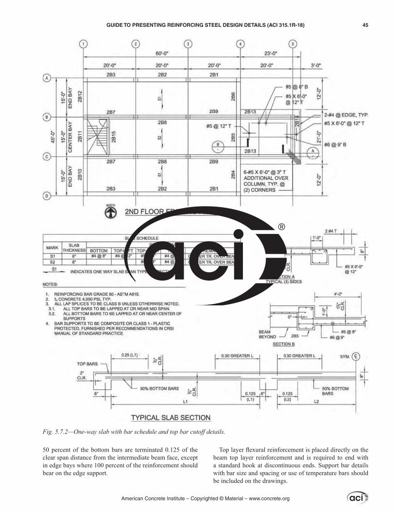
50 percent of the bottom bars are terminated 0.125 of the clear span distance from the intermediate beam face, except in edge bays where 100 percent of the reinforcement should bear on the edge support.
Top layer flexural reinforcement is placed directly on the beam top layer reinforcement and is required to end with a standard hook at discontinuous ends. Support bar details with bar size and spacing or use of temperature bars should be included on the drawings.
Fig. 5.7.2—One-way slab with bar schedule and top bar cutoff details.
American Concrete Institute – Copyrighted © Material – www.concrete.org
GUIDE TO PRESENTING REINFORCING STEEL DESIGN DETAILS (ACI 315.1R-18) 45
Transverse temperature bars run continuously with the specified lap and are required to run through intermediate supporting members and at end supports are embedded a minimum of 6 in. (150 mm).
Terminations of top bars and bottom bars should be clearly dimensioned in the contract documents. Support members should be clearly marked. Calculations used for the top bar projections should be based on the clear distance between supports. Construction, contraction, isolation, and expansion joints should be located and dimensioned on the contract documents to ensure accurate placing of the reinforcement and required dowels. Standard hooks for the development of deformed bars in tension should conform to ACI 318-14 Table 25.3.1. Refer to Fig 5.7.2.
5.7.3 Two-way slabs—ACI 318-14 Chapter 8 provides reinforcement design requirements for two-way slabs (Fig. 5.7.3). Slab bottom layer flexural reinforcement is placed in both directions, runs continuously across the span, and is anchored in the support a minimum of 6 in. (150 mm).
Slab top layer reinforcement is placed in both directions directly on the top layer beam reinforcement and is required to terminate with a standard hook at discontinuous ends. Support bar details with bar size and spacing should be included on the drawings.
Specific details for bar layering at openings and varying span widths should be included in the contract documents. Construction, contraction, isolation, and expansion joints should be located and dimensioned on the contract docu-ments to ensure accurate placing of the reinforcement and required dowels. Standard hooks for the development of deformed bars in tension should conform to ACI 318-14 Table 25.3.1.
5.7.4 Edges and openings—Standard hooks for the devel-opment of deformed bars in tension should conform to ACI 318 Table 25.3.1. If hooks are required at discontinuous end, the LDP should verify the hook dimension can be placed within the specified slab thickness. Details of bar conditions at slab edges and openings should be included in the contract documents. Trim bars should be shown in specific details on the drawings.
5.7.5 Steps and depressions—Design details for steps and depressions should be presented separately for different step dimensions (Fig. 5.7.5(a) and (b)). This should include directions for draping the main reinforcement, hooking and lapping, or furnishing a bent bar. Attention should be given to providing continuous and correctly anchored reinforce-ment across any section change. Dimensions of steps and depressions should be clearly shown on the structural draw-ings and located from grid lines or from concrete edge.
CHAPTER 6—REVIEW OF PLACING DRAWINGS
6.1—ScopeThe information found in this chapter is intended to
provide a general overview of the definition, purpose, review process, and use of reinforcing steel placing drawings. For more specific information and guidelines, refer to Chapter 6 of the CRSI Manual of Standard Practice (2017). Addition-
ally, for a better understanding of the fundamentals and best practices in the preparation of reinforced concrete placing drawings, refer to CRSI Reinforcing Bar Detailing (2015).
6.2—DefinitionPlacing drawings are working documents that show the
quantity, bar size, dimensions, and location of reinforcing steel as required for fabrication and placement. Placing drawings may comprise plans, details, elevations, schedules, material lists, and bending details. They can be prepared manually or by computer.
6.3—OverviewPlacing drawings are the fabricator’s interpretation of
the licensed design professional’s (LDP’s) design intent as defined in the contract documents. The purpose is to assure proper fabrication and placement of reinforcing steel. The contract documents, plus changes issued by the LDP (per terms agreed upon in the contract if issued after the contract is made), constitute the sole authority for information in placing drawings. Because no new design intent is added during the creation of placing drawings, they do not require an engineer’s seal. The LDP should furnish a clear state-ment of the design requirements in the project specifications and structural drawings, and should not refer the fabrication detailer to an applicable building code or other codes for information necessary to prepare the placing drawings. Such information should be provided by the LDP in the form of specific design details or notes.
Necessary additional information such as field condi-tions, field measurements, location of construction joints, and sequence of placing concrete should be supplied by the contractor. Information supplied by the contractor should be provided in a timely manner so that complete placing draw-ings can be provided to meet deadlines required for rein-forcement fabrication (Birley 2008). It is more important that placing drawings be prepared based on available infor-mation required by the reinforcing steel detailer to accurately complete the drawings. This includes shop drawings from other trades that are approved for construction. All parties need to work together to complete submittal, review, and approval processes in a timely manner that does not impact construction schedules. After review by the LDP, including necessary revisions, the drawings can be used for fabrication and placing of reinforcing steel.
6.4—ProcedurePlacing drawings are most commonly prepared by a
detailer, typically employed or contracted by the reinforcing steel fabricator. General steps for producing and using placing drawings are:
(1) Detailer prepares placing drawings based on informa-tion found in the project specifications and structural draw-ings, as well as information related to construction require-ments obtained from the contractor.
(2) Placing drawings are submitted to the contractor or their designee for review and approval. On many projects, the contractor will also forward the placing drawings to the
American Concrete Institute – Copyrighted © Material – www.concrete.org
46 GUIDE TO PRESENTING REINFORCING STEEL DESIGN DETAILS (ACI 315.1R-18)
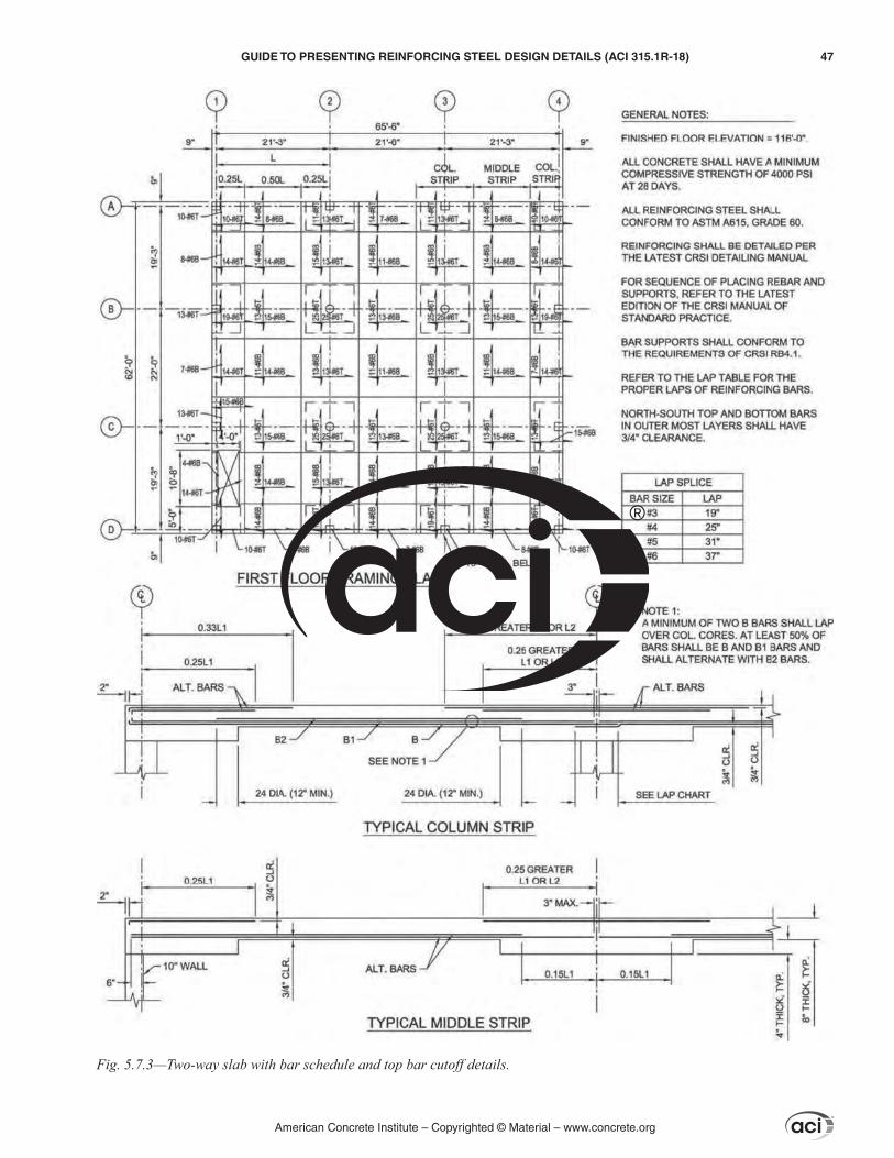
Fig. 5.7.3—Two-way slab with bar schedule and top bar cutoff details.
American Concrete Institute – Copyrighted © Material – www.concrete.org
GUIDE TO PRESENTING REINFORCING STEEL DESIGN DETAILS (ACI 315.1R-18) 47

LDP for their review and approval. Refer to Sections 6.5 and 6.6 of this guide for detailed explanations of placing drawing review and approval processes.
(3) Once placing drawings have been approved, bar fabri-cation lists are prepared from the bar lists on the placing drawings, based on a delivery sequence agreed on between the fabricator and the contractor.
(4) Releases are submitted for fabrication in accordance with the current delivery schedule.
(5) Reinforcing steel is cut, bent, tagged, bundled, and delivered to the job site along with other material, such as bar supports, as specified in the contract.
(6) Reinforcing steel is installed based on details found on the placing drawings and in accordance with requirements of the contract documents.
6.5—Review of placing drawingsPractices and requirements for LDP review of placing draw-
ings vary by geographic region, as well as by the nature of the project and client. In some geographic regions, it is customary for the LDP to review the placing drawings. In other regions, this is rarely done. For some types of projects—usually larger or publicly funded projects—review by the LDP is required by the owner. Review of the placing drawings by the LDP can reduce errors, lost production time, and rework during inspec-tion, and is encouraged as a good practice.
6.5.1 Benefits of review—Review is deemed to have several worthwhile benefits, including:
(a) A tendency to include the LDP as part of the team effort(b) Verification conformance with general design intent(c) Verification that the most recent revised contract draw-
ings have been used(d) Catching and correcting small errors or omissions that
would otherwise delay the project if left to be discovered during inspection in the field
(e) Providing assurance that the detailer understands the design concepts and is proceeding correctly
(f) Allowing reviewed placing drawings to form a large part of the “As-built” documents package
Most project specifications allow a given period of time for the LDP review of placing drawings—in most cases, 2 weeks. The detailer and construction team factor this review time into their schedules. Therefore, it is important for the LDP to work within this time constraint to help keep the project on schedule.
6.5.2 Review process—Ideally the process for submission and review of placing drawings should be outlined in the contract documents. Although the process varies from each project, it generally will include the following steps:
(1) Detailer submits the placing drawings to the contractor or their designee
Fig. 5.7.5—Slab step details (a) and (b).
American Concrete Institute – Copyrighted © Material – www.concrete.org
48 GUIDE TO PRESENTING REINFORCING STEEL DESIGN DETAILS (ACI 315.1R-18)

(2) Contractor or their designee reviews the drawings and forwards them to the LDP
(3) LDP completes their review and returns the drawings to the contractor in a timely manner
(4) Reviewed drawings are returned to the detailer(5) Detailer makes all necessary amendments and either
resubmits if required, or authorizes the detailed reinforcing steel for fabrication
6.5.3 Checklists for review of placing drawings—Although the LDP will have an individual checklist, it generally will include at least the following items:
(a) Verification of the latest issue of contract drawings(b) Verification of the latest issue of addenda and supple-
mentary documents, such as requests for information (RFIs), design change notices (DCNs), and field change notices (FCNs)
(c) Verification of grades, coatings, and sizes of rein-forcing steel
(d) Verification that all reinforcing steel has been included and properly located
6.6—Levels of approvalThere are many variations of approval levels. Each LDP
usually develops one that suits individual requirements. Although terms can vary, most will include, as a minimum, the following levels:
(a) Approved––These drawings meet all design require-ments and are approved for fabrication and installation.
(b) Approved as noted––These drawings require small corrections that do not impact the design intent. Once corrections are completed they are approved for fabrication and installation. Resubmittal is not required.
(c) Revise and resubmit––These drawings have significant errors that impact the design intent or do not comply with the specifications. The LDP requires resubmittal.
(d) Not approved––These drawings do not meet the design intent. Alternately, perhaps, the LDP is aware that new or revised design documents are about to be issued that will supersede previous contract drawings. In either case, entirely new placing drawings are required and submitted.
The LDP normally reviews the placing drawings for general conformance with the contract documents, but does not materially change the design or make contract amend-ments in that review. Errors or omissions in the placing drawings are not generally the responsibility of the LDP.
CHAPTER 7—REFERENCESACI committee documents and documents published by
other organizations are listed first by document number, full title, and year of publication followed by authored docu-ments listed alphabetically.
American Concrete InstituteACI 117-10(15)—Specification for Tolerances for
Concrete Construction and Materials and CommentaryACI 131.1R-14—Information Delivery Manual for Cast-
in-Place Concrete
ACI 132R-14—Guide for Responsibility in Concrete Construction
ACI 301-16—Specifications for Structural ConcreteACI 314R-16––Guide to Simplified Design for Rein-
forced Concrete BuildingsACI 318-11––Building Code Requirements for Structural
Concrete and CommentaryACI 318-14—Building Code Requirements for Structural
Concrete and CommentaryACI 336.3R-14—Report on Design and Construction of
Drilled PiersACI 421.1R-08—Guide to Shear Reinforcement for SlabsACI 543R-12––Guide to Design, Manufacture, and Instal-
lation of Concrete Piles
American Institute of ArchitectsAIA Document G202™-2013—Project Building Informa-
tion Modeling Protocol Form
American Welding SocietyAWS D1.4/D1.4M:2011—Structural Welding Code –
Reinforcing SteelAWS D1.6/D1.6M:2007—Structural Welding Code –
Stainless Steel
ASTM InternationalASTM A615/A615M-16—Standard Specification for
Deformed and Plain Carbon-Steel Bars for Concrete Reinforcement
ASTM A706/A706M-16—Standard Specification for Deformed and Plain Low-Alloy Steel Bars for Concrete Reinforcement
ASTM A1064/A1064M-16—Standard Specification for Carbon-Steel Wire and Welded Wire Reinforcement, Plain and Deformed, for Concrete
BIMForumLOD 2016—Level of Development (LOD) Specification
Concrete Reinforcing Steel InstituteCRSI––Manual of Standard Practice, 29th Edition, 2017CRSI—Reinforcing Bar Detailing, Fifth Edition, 2015CRSI RB4.1-2016—Supports for Reinforcement Used in
Concrete
Construction Specifications InstituteCSI UniFormat™ 2010: A Uniform Classification of
Construction Systems and Assemblies
International Code CouncilIBC 2015—International Building Code
International Organization for StandardizationISO 16739:2013—Industry Foundation Classes (IFC)
National Institute of Building SciencesNBIMS-US™ 2015—National BIM Standard-United
States, Version 3
American Concrete Institute – Copyrighted © Material – www.concrete.org
GUIDE TO PRESENTING REINFORCING STEEL DESIGN DETAILS (ACI 315.1R-18) 49

NCS-V6—United States National CAD Standard®
Wire Reinforcement Institute®
WWR-500-R-16—Manual of Standard Practice––Struc-tural Welded Wire Reinforcement
WWR-600—Structural Detailing Manual 2006
Authored documentsBirley, D., 2005, “The Tolerance Cloud,” Concrete Inter-
national, V. 27, No. 6, June, pp. 61-63.Birley, D., 2008, “Reinforcing Placing Drawings are not
Shop Drawings,” Concrete International, V. 30, No. 12, Dec., pp. 48-50.
American Concrete Institute – Copyrighted © Material – www.concrete.org
50 GUIDE TO PRESENTING REINFORCING STEEL DESIGN DETAILS (ACI 315.1R-18)


As ACI begins its second century of advancing concrete knowledge, its original chartered purpose remains “to provide a comradeship in finding the best ways to do concrete work of all kinds and in spreading knowledge.” In keeping with this purpose, ACI supports the following activities:
· Technical committees that produce consensus reports, guides, specifications, and codes.
· Spring and fall conventions to facilitate the work of its committees.
· Educational seminars that disseminate reliable information on concrete.
· Certification programs for personnel employed within the concrete industry.
· Student programs such as scholarships, internships, and competitions.
· Sponsoring and co-sponsoring international conferences and symposia.
· Formal coordination with several international concrete related societies.
· Periodicals: the ACI Structural Journal, Materials Journal, and Concrete International.
Benefits of membership include a subscription to Concrete International and to an ACI Journal. ACI members receive discounts of up to 40% on all ACI products and services, including documents, seminars and convention registration fees.
As a member of ACI, you join thousands of practitioners and professionals worldwide who share a commitment to maintain the highest industry standards for concrete technology, construction, and practices. In addition, ACI chapters provide opportunities for interaction of professionals and practitioners at a local level to discuss and share concrete knowledge and fellowship.
American Concrete Institute38800 Country Club DriveFarmington Hills, MI 48331Phone: +1.248.848.3700Fax: +1.248.848.3701
www.concrete.org
38800 Country Club Drive
Farmington Hills, MI 48331 USA
+1.248.848.3700
www.concrete.org
The American Concrete Institute (ACI) is a leading authority and resource
worldwide for the development and distribution of consensus-based
standards and technical resources, educational programs, and certifications
for individuals and organizations involved in concrete design, construction,
and materials, who share a commitment to pursuing the best use of concrete.
Individuals interested in the activities of ACI are encouraged to explore the
ACI website for membership opportunities, committee activities, and a wide
variety of concrete resources. As a volunteer member-driven organization,
ACI invites partnerships and welcomes all concrete professionals who wish to
be part of a respected, connected, social group that provides an opportunity
for professional growth, networking and enjoyment.
9 781945 487965


![Microstructure Characteristics of GFRP Reinforcing Bars in ...2019/01/15 · ACI 440.3R & ASTM D7205 [3, 16] Tensile strain (%) ACI 440.3R & ASTM D7205 [3, 16] Tensile modulus (MPa)](https://static.fdocuments.net/doc/165x107/60b50b9c12845f3fce7fef1e/microstructure-characteristics-of-gfrp-reinforcing-bars-in-20190115-aci.jpg)