
Guide to Optimum Marine Coating Application - Part 1 - Environmental Conditions Testing and...
44
Guide to Optimum Marine Coating Application Part 1 Environmental Conditions Testing and Monitoring by Alexandros Michelis 1
description
Guide to Optimum Marine Coating Application - Part 1 - Environmental Conditions Testing and Monitoring by Alexandros Michelis
Transcript of Guide to Optimum Marine Coating Application - Part 1 - Environmental Conditions Testing and...

Guide to Optimum
Marine Coating Application
Part 1
Environmental Conditions
Testing and Monitoring
by Alexandros Michelis
1

Environmental Conditions Testing & Monitoring
2
General
• Environmental conditions are crucial to all stages of
coating process (surface preparation, coating application
and curing).
• Optimal environmental conditions:
o Key to high quality surface preparation.
o Key to high quality coating application.
o Maximize service life and in service performance of
the coating.
• Ensuring optimal environmental conditions should be
continuous throughout the whole coating process.

Environmental Conditions Testing & Monitoring
3
General
• The majority of shipyards and marine construction /
repair facilities carry out most or all construction / repair
work outdoors. Only few have the means to perform
surface preparation and coating application under cover
and under controlled environmental conditions.
• Optimal environmental conditions for the application of a
coating may differ from product to product and relevant
information is provided by the manufacturer.
• Special products exist for application in extreme / severe
environmental conditions.
Environmental Conditions Testing & Monitoring
4
General
• Proper inspection of the coating process should include
testing / monitoring of the environmental conditions.
• Testing / Monitoring of environmental conditions is part of
the job of the coating inspector.
• Environmental conditions should be addressed by the
job specification.

Environmental Conditions Testing & Monitoring
5
Environmental Conditions Affecting Coating
Application
• Substrate temperature
• Ambient conditions:
o Air temperature
o Relative humidity
o Dew point
o Wind
• Contaminants (soluble salts, dust, debris, exhaust
fumes, oil, grease, flame burns, etc)

Environmental Conditions Testing & Monitoring
6
Substrate Temperature
• Substrate: surface to be coated (metal, wood, composite
material, etc)
• Need to follow coating manufacturer’s recommendations
concerning upper and lower limits of substrate
temperature during coating application.
• Relative information should be obtained from coating
technical data sheet or directly from the manufacturer.
Environmental Conditions Testing & Monitoring
7
Substrate Temperature
• Substrate temperature too low → substrate temperature
≤ dew point → condensation of moisture → flash rusting
of blasted steel → poor performance of applied coating /
coating failure.
• Substrate temperature too high → rapid solvent
evaporation → film formation failures and poor wetting of
surface (poor coating flow).

Environmental Conditions Testing & Monitoring
8
Substrate Temperature
Instruments used to measure substrate temperature are:
• Magnetic surface-contact thermometer. Analogue
function. Cheapest and most common type of gauge.
Direct measuring. Need time to stabilize.
• Direct-reading thermocouple / thermistor. Digital
instrument. Direct measuring. Fast reading.
• Infrared thermometer (laser thermometer). Digital
instrument. No need for contact. Fast reading.

Environmental Conditions Testing & Monitoring
9
Substrate Temperature
Remarks:
• Measurements should be made at the actual surface to
be coated, and not to adjacent structures.
• The number of measurements should provide sufficient
temperature mapping of the substrate.
• Need to pay special attention to hotter or colder areas of
the structure, such as areas exposed to direct sunlight.

Environmental Conditions Testing & Monitoring
10
Air Temperature
• Affects directly the coating process.
• Increased air temperature causes acceleration of solvent
evaporation and drying of the coating, which can result in
failures such as poor wetting or film formation defects
(mud cracking, alligatoring).
• Too low air temperature can cause inability of the coating
to dry / cure after application.
• Coating manufacturer’s recommendations concerning
upper and lower limits of air temperature during coating
application and curing must be followed. Relevant
information should be obtained from coating technical
data sheet or directly from the manufacturer.

Environmental Conditions Testing & Monitoring
11
Air Temperature
• Job specifications may also provide limits of air
temperature.
• For example, NATO AEP-611 defines application
temperature to be no less than 5°C, and no greater than
35°C.
1 NATO PUBLICATION AEP-61, EDITION 2, PERFORMANCE REQUIREMENTS FOR UNDERWATER HULL PAINT
SYSTEMS, FEBRUARY 2009.

Environmental Conditions Testing & Monitoring
12
Relative Humidity
• Relative Humidity (RH): measurement of the amount of
moisture in the air compared to saturation level (0-
100%).
• Coating specifications / manufacturers provide upper
and lower limits of RH during coating application,
depending on the coating type and the environment in
which it is applied.
• General rule for most coatings when coating outdoors:
maximum RH = 80-85%.
• According to NATO AEP-591, maximum RH when
coating tanks, voids and vent plenums should be 50%.
1 NATO PUBLICATION AEP-59, EDITION 1, APPLICATION PROCESS FOR OPTIMUM PAINT AND COATING
SYSTEM’S PERFORMANCE, SEPTEMBER 2006

Environmental Conditions Testing & Monitoring
13
Relative Humidity
• Too high RH blocks solvent evaporation and affects
curing. Furthermore, solvent vapors can be entrapped
and cause formation of blisters.
• Coatings exposed to high RH after application often
display coating defects such as blushing (amine
sweating).
• Waterborne coatings, which use water as solvent, are
more likely to be affected by high RH.

Environmental Conditions Testing & Monitoring
14
Dew Point
• Dew Point (DP): temperature below which water vapor in
air condenses into liquid water, leaving dew on a solid
surface.
• Dew will cause rapid rusting of freshly blasted steel
(flash rust).
• Moisture trapped between two coating films can cause
failure (delamination, peeling) due to loss of adhesion.
• High RH indicates that DP is also high and close to the
current air temperature.

Environmental Conditions Testing & Monitoring
15
Dew Point
• Newly blasted surfaces should receive the first protective
coat (primer, self-primed epoxy, etc) as soon as possible,
and before nightfall, especially if surface preparation is
performed outdoors.
• General rule: blast cleaning and coating application
should not take place unless surface temperature is at
least 3°C (5°F) higher than the dew point.

Environmental Conditions Testing & Monitoring
16
DP & RH Measurement
• Instruments used to measure dew point / relative humidity
are analogue or digital psychrometers / hygrometers.
• Operating principle: measurement of the air temperature
(dry-bulb temperature) and of the so-called wet-bulb
temperature. This information is used to calculate dew
point and RH.

Environmental Conditions Testing & Monitoring
17
DP & RH Measurement – Analogue (Sling) Psychrometer
• Instrument enclosing two identical thermometers.
• The bulb of one of the thermometers is covered with a
sock / wick. This bulb is called “wet bulb”, because it is wet
/ saturated in water prior to the measuring process.
• The second bulb is called “dry bulb”.

Environmental Conditions Testing & Monitoring
18
Operation of Sling Psychrometer
Steps (1):
• Saturate the sock / wick of the wet bulb with distilled
water.
• Spin the instrument fast for about 40 seconds, and
then read the wet-bulb temperature. Spinning causes
the evaporation of moisture on the wet-bulb, thus
having a cooling effect.
(source: ABS)

Environmental Conditions Testing & Monitoring
19
Operation of Sling Psychrometer
Steps (2):
• Repeat the spinning process without additional wetting
until the temperature reading of the wet-bulb is stable.
• Record the wet-bulb temperature.
• Record the dry-bulb temperature.
• Calculate the wet-bulb depression (difference between
dry and wet-bulb temperature).
(source: ABS)

Environmental Conditions Testing & Monitoring
20
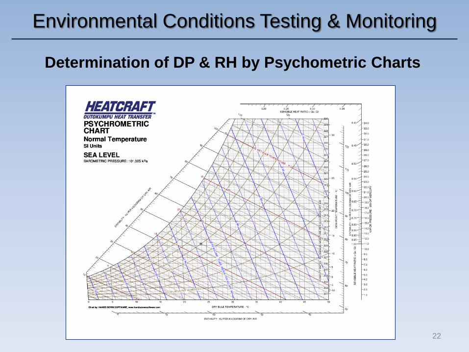
Determination of DP & RH by Psychometric Tables
• Use of psychrometric table: Enter the table with the dry-bulb
temperature (vertical axis) and the wet-bulb temperature /
depression (horizontal axis), and read the intersection of the
their values. The reading corresponds to the relevant value of
dew point (or relative humidity, depending on the table).

Environmental Conditions Testing & Monitoring
21
Determination of DP & RH by Psychometric Tables
• Remark: DP and RH vary with atmospheric pressure. The
atmospheric pressure is not constant, but changes with
altitude and weather.
• Series of psychrometric tables are provided for different
values of atmospheric pressure. Typically, one should first
measure the atmospheric pressure by using a barometer,
and then refer to the respective psychrometric table.
• The table referring to an atmospheric pressure equivalent to
the average sea-level pressure (101.325 kPa or 1013.25
mbar or 29.92 inches of mercury (inHg) or 760 millimeters of
mercury (mmHg)) may be used with small error.
• Psychrometric charts and calculators use the same principle
with the psychrometric tables.
Environmental Conditions Testing & Monitoring
22
Determination of DP & RH by Psychometric Charts

Environmental Conditions Testing & Monitoring
23
Determination of DP & RH by Psychometric Calculators

Environmental Conditions Testing & Monitoring
24
Control of RH
• By using heat to increase temperature.
• By dehumidification (by circulating air through a
refrigeration unit or desiccants).

Environmental Conditions Testing & Monitoring
25
Wind
• Wind effects must be taken into consideration during all
stages of coating application.
• Wind can have an unfavorable and even detrimental effect
by carrying contaminants (dust, debris, abrasives, salts,
etc) on the substrate before / during / after surface
preparation and coating application. These surface
contaminants may cause cosmetic problems, but most
importantly, may become inclusions and cause coating
defects / failure.
• Wind can cause dry spray during application (coating
defect). It appears like sand / dust on the coating surface.

Environmental Conditions Testing & Monitoring
26
Wind
• Can accelerate solvent evaporation during curing, causing
film formation defects and poor wetting of surface.
• Can cause overspray during coating application (loss of
coating, cosmetic problems, collateral damage).

Environmental Conditions Testing & Monitoring
27
Contaminants – Soluble Salts
• The significance of contamination by soluble salts and their
impact on marine structures has been recognized by the
marine industry for long time.
• The most common salts in marine industry are chloride
compounds (sodium chloride) due to the proximity to
seawater (direct contact, spray carried by the wind, etc).
• It has been reported that a small increase in the chloride
salt content (+1μg/cm2) can lead to a 200% decrease in
the lifetime of an epoxy resin coating1.
• Other salts are sulfurous compounds (generated in
industrial environments) and nitrogenous compounds
(generated in urban environments). 1 A.W. MOMBER AND W.D. GREVERATH, SURFACE PREPARATION STANDARDS FOR STEEL SUBSTRATES
- A CRITICAL REVIEW, JPCL, THE JOURNAL OF PROTECTIVE COATINGS & LININGS, FEBRUARY 2004

Environmental Conditions Testing & Monitoring
28
Contaminants – Soluble Salts
• Soluble salts form deposits on the substrate, which can
cause coating failure:
o By inducing corrosion under the coating film. Their
chemical reaction with the substrate creates new
compounds, which are electrochemically bound to the
surface and form active corrosion cells.
o By promoting osmotic blistering, which is one of the
most common coating defects in marine environment.
o By causing loss of adhesion (delamination, peeling).
• Soluble salts boost corrosion (galvanic, pitting, crevice,
etc) by increasing the efficiency of the electrolyte (humid
air, dew, water) and the ion concentration.

Environmental Conditions Testing & Monitoring
29
Contaminants – Soluble Salts
Osmotic blistering: Formation of a hemispherical projection
(blister) by drawing water through the coating, from an area of
low ionic concentration to an area of high ionic concentration.
Schematic osmotic blister formation (source: ABS1)
1 ABS,GUIDANCE NOTES ON THE INSPECTION, MAINTENANCE AND APPLICATION OF MARINE COATING
SYSTEMS, 3RD EDITION, 2007

Environmental Conditions Testing & Monitoring
30
Testing for Soluble Salts
• Proper inspection during the coating process should include
testing for soluble salts.
• Usually, testing for soluble salts takes place after the stage
of surface preparation and prior to coating application.
• Optimally, testing for soluble salts should be performed
before the stage of surface preparation.
• Abrasive blasting or power tool cleaning might not remove
soluble salts effectively or even cause “pinning” / spreading
of the salt compounds on the substrate.
• If soluble salts are detected on the substrate, corrective
measures may be required, depending on the acceptable
level of contamination by the applied standard /
specification.

Environmental Conditions Testing & Monitoring
31
Testing for Soluble Salts
Two methods:
• Chloride testing
o Measures chloride ions concentration.
o Units:
Surface concentration: μg/cm2, mg/m2
Volumetric concentration: μg/cm3 (ppm)
o Sulfates and nitrates concentrations can also be measured.
• Conductivity testing
o Measures conductivity of a sample (ability to conduct
electricity).
o Measures more than just chlorides (total ionic content).
o Units: μS/cm (microsiemens/cm)
Environmental Conditions Testing & Monitoring
32
Testing for Soluble Salts
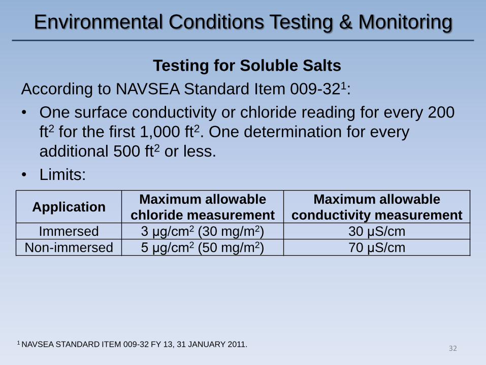
According to NAVSEA Standard Item 009-321:
• One surface conductivity or chloride reading for every 200
ft2 for the first 1,000 ft2. One determination for every
additional 500 ft2 or less.
• Limits:
1 NAVSEA STANDARD ITEM 009-32 FY 13, 31 JANUARY 2011.
Application Maximum allowable
chloride measurement Maximum allowable
conductivity measurement Immersed 3 μg/cm2 (30 mg/m2) 30 μS/cm
Non-immersed 5 μg/cm2 (50 mg/m2) 70 μS/cm

Environmental Conditions Testing & Monitoring
33
Testing for Soluble Salts
• According to NATO AEP-591, “for immersed applications,
concentration due to soluble salts (total ionic) shall not
exceed 5μg/cm2. For non-immersed applications,
concentration due to soluble salts (total ionic) shall not
exceed 10μg/cm2”.
• According to IMO PSPC2, the water soluble salt limit
(equivalent to NaCl) of dedicated seawater ballast tanks is ≤
50mg/m2 (5μg/cm2) of sodium chloride.
1 NATO PUBLICATION AEP-59 EDITION 1, APPLICATION PROCESS FOR OPTIMUM PAINT AND COATING
SYSTEM’S PERFORMANCE, SEPTEMBER 2006 2 IMO RESOLUTION MSC.215(82), PERFORMANCE STANDARD FOR PROTECTIVE COATINGS FRO
DEDICATED SEAWATER BALLAST TANKS IN ALL TYPES OF SHIPS AND DOUBLE-SIDE SKIN SPACES OF
BULK CARRIERS, ADOPTED ON 8 DECEMBER 2006
Environmental Conditions Testing & Monitoring
34
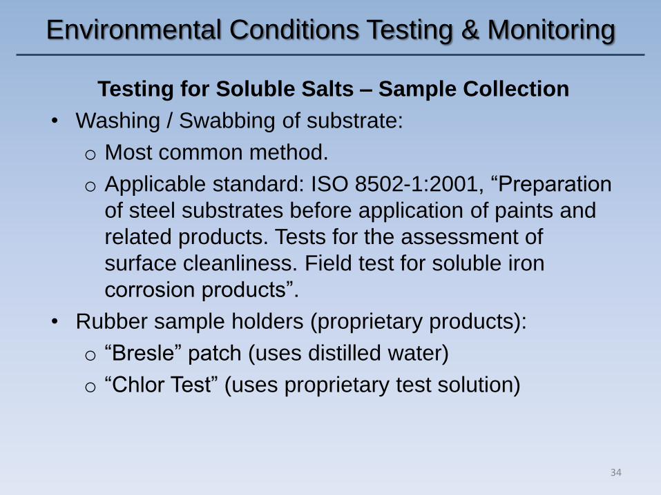
Testing for Soluble Salts – Sample Collection
• Washing / Swabbing of substrate:
o Most common method.
o Applicable standard: ISO 8502-1:2001, “Preparation
of steel substrates before application of paints and
related products. Tests for the assessment of
surface cleanliness. Field test for soluble iron
corrosion products”.
• Rubber sample holders (proprietary products):
o “Bresle” patch (uses distilled water)
o “Chlor Test” (uses proprietary test solution)

Environmental Conditions Testing & Monitoring
35
Testing for Soluble Salts – Testing Liquid Samples
• Indicator papers
• Kitagawa tubes
• Lab tests
• Conductivity measurement
Environmental Conditions Testing & Monitoring
36
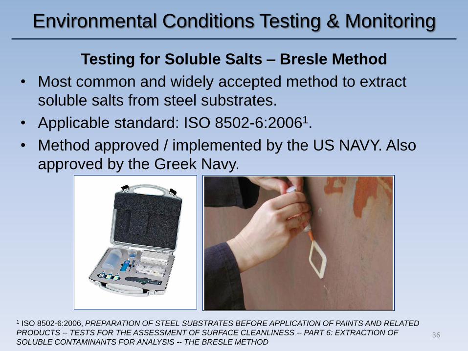
Testing for Soluble Salts – Bresle Method
• Most common and widely accepted method to extract
soluble salts from steel substrates.
• Applicable standard: ISO 8502-6:20061.
• Method approved / implemented by the US NAVY. Also
approved by the Greek Navy.
1 ISO 8502-6:2006, PREPARATION OF STEEL SUBSTRATES BEFORE APPLICATION OF PAINTS AND RELATED
PRODUCTS -- TESTS FOR THE ASSESSMENT OF SURFACE CLEANLINESS -- PART 6: EXTRACTION OF
SOLUBLE CONTAMINANTS FOR ANALYSIS -- THE BRESLE METHOD

Environmental Conditions Testing & Monitoring
37
Testing for Soluble Salts – Chlor Method
• Measures chlorides.
• Applicable standard: ISO 8502-5:19981.
1 ISO 8502-5:1998, PREPARATION OF STEEL SUBSTRATES BEFORE APPLICATION OF PAINTS AND RELATED
PRODUCTS -- TESTS FOR THE ASSESSMENT OF SURFACE CLEANLINESS -- PART 5: MEASUREMENT OF
CHLORIDE ON STEEL SURFACES PREPARED FOR PAINTING (ION DETECTION TUBE METHOD)

Environmental Conditions Testing & Monitoring
38
• Replicates the Bresle process (ISO
8502-6).
• Automated.
• According to manufacturer, 8x faster
compared to the Bresle Patch method.
Total process time: 1 min.
• Equivalent to ISO 8502-9 (the field
method for the conductometric
determination of soluble salts).
• Approved / Implemented by the US Navy1.
Testing for Soluble Salts – Soluble Salt Meter
by HedoN Electronic Developments
(ARP Soluble Salt Meter model RPCT-07-001)
1 NAVSEA STANDARD ITEM 009-32 FY-13

Environmental Conditions Testing & Monitoring
39
Testing for Soluble Salts – Soluble Salt Meter
by HedoN Electronic Developments
(ARP Soluble Salt Meter model RPCT-07-001)

Environmental Conditions Testing & Monitoring
40
Testing for Soluble Salts – SaltSmart
by Innovative Productivity, Inc.
• Developed over a 5 year
program with funding from the
US Navy1.
• One-time-use disposable
sensor. Multiple tests can be
run in parallel.
• According to manufacturer,
sample time: 8 min for strip
development, 15 sec for meter
analysis .
• Equivalent to ISO 8502-9.
1 NAVSEA STANDARD ITEM 009-32 FY-13
Environmental Conditions Testing & Monitoring
41
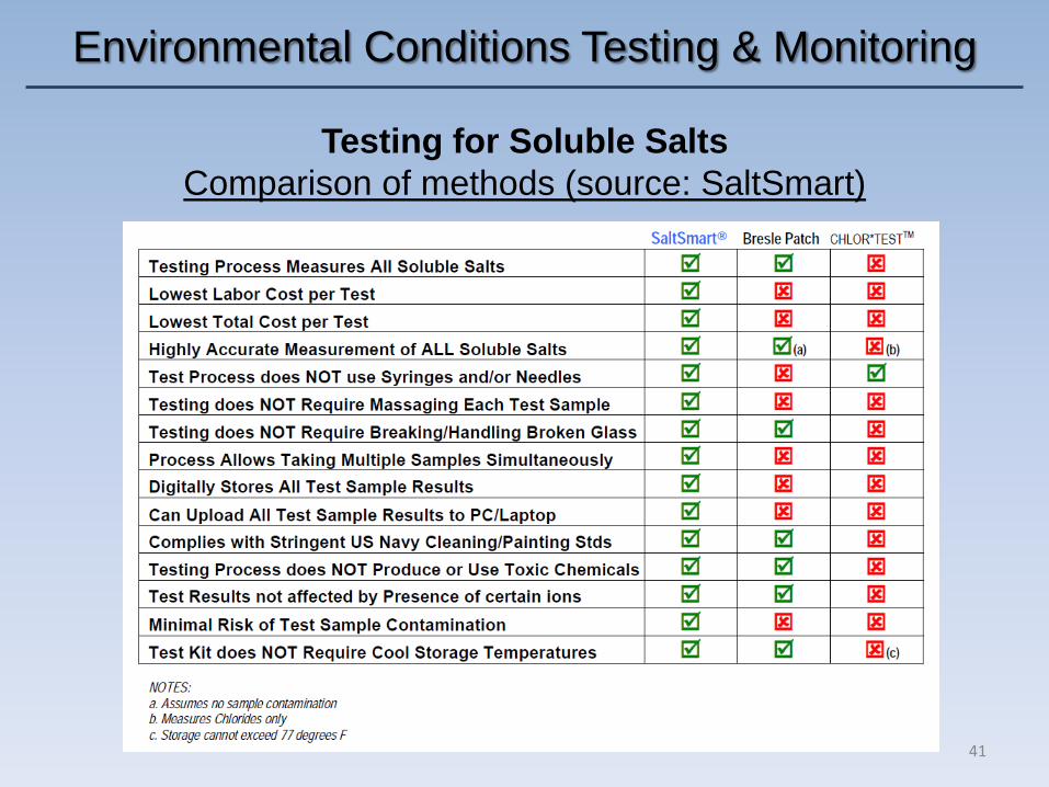
Testing for Soluble Salts
Comparison of methods (source: SaltSmart)

Environmental Conditions Testing & Monitoring
42
Removal of Soluble Salts
• Soluble salts should be removed (dissolved) by clean fresh
water washing. Pressure (< 70 MPa) may be used1.
• Most specifications call for a 3000 psi ≈ 20.7 MPa wash
down.
1 According to ISO 12944-4:1998, PAINTS AND VARNISHES. CORROSION PROTECTION OF STEEL
STRUCTURES BY PROTECTIVE PAINT SYSTEMS. TYPES OF SURFACE AND SURFACE PREPARATION.

Environmental Conditions Testing & Monitoring
43
Removal of Soluble Salts
• Removal of soluble salts should take place before the
stage of surface preparation by abrasive blasting or hand /
power tool cleaning.
• According to NSTM 6311, “for all types of substrate
materials, before surface preparation to the specified
cleanliness level using any method other than waterjetting
or wet abrasive blasting, the area to be cleaned shall be
washed with low pressure freshwater to remove any
residual soluble salts”. For best efficiency, the freshwater
used should have a maximum conductivity of 200 μS/cm.
1 NAVAL SHIPS’ TECHNICAL MANUAL CHAPTER 631, REVISION 3, PRESERVATION OF SHIPS IN SERVICE –
GENERAL, 1 NOVEMBER 2008

Environmental Conditions Testing & Monitoring
44
1 ISO 12944-4:1998, PAINTS AND VARNISHES. CORROSION PROTECTION OF STEEL STRUCTURES BY
PROTECTIVE PAINT SYSTEMS. TYPES OF SURFACE AND SURFACE PREPARATION.
Removal of Soluble Salts
• Repeat water wash and retest until satisfactory levels of salt
contamination are obtained.
• The presence of pitting corrosion on the substrate makes the
removal of soluble salt contamination more difficult and time
consuming.
• Other options (according to ISO 12944-4:19981): steam
cleaning and alkaline cleaning.
Residual contamination in pits (source: ABS)


