Guide to EIFS ConstructionGuideto EIFS...
15
Fig. 2 CONCRETE AND MASONRY EIFS attached to concrete or masonry using adhesive. Mechanical fasteners may also be used. Finish Coat Reinforcing Mesh Embedded in Base Coat Base Coat Insulation Board Adhesive Applied To Concrete Or Masonry Substrate Fig. 1 STEEL OR WOOD FRAMING EIFS may be attached by mechanical fasteners (as shown) or by adhesive (as shown below). Fasteners Insulation Board Wood or Steel Framing Reinforcing Mesh Substrate Base Coat Embedded in Base Coat Finish Coat Insulation Board 2000 EIMA ISSUE: 6/00 Printed in U.S.A. These drawings and comments are for general information only, and EIMA specifically disclaims any design or construction intent or responsibility. THERE ARE NO WARRANTIES, EXPRESS OR IMPLIED, ISSUED OR MADE BY EIMA IN CONNECTION WITH THESE DRAWINGS AND COMMENTS OR REGARDING THE USE OF EIFS. These drawings are not intended and should not be used as a substitute for the EIFS system manufacturer's specifications and recommended construction practices and/or for professional building design services. The specification, design and construction of all EIFS must comply with local building codes and standards, applicable compliance reports and the individual manufacturer's system requirements. These requirements differ materially. Only the EIFS manufacturer or design professional can furnish specifications, details, drawings, and construction practices to be followed for actual construction and use of an EIFS product and for compliance with applicable local building codes and construction practices. The successful installation and performance of EIFS cladding is dependent upon the proper design and construction of the adjacent materials and systems of the structure. For these reasons, only a licensed and qualified design professional can create and issue specifications, drawings and details for actual or prospective construction or renovation using EIFS. These drawings and comments apply only to new construction beginning in 2000, and are not intended for inspections, retrofit or repair. These drawings are not intended as an exclusive method for achieving desired performance. Alternative configurations may achieve equal or better performance. These drawings and comments apply only to complete EIFS products as specifically defined in the current edition of EIMA Classification Paper. EIFS Industry Members Association 3000 Corporate Center Drive Morrow, GA 30260 (800) 294-3462 TYPICAL EIFS CONFIGURATION Guide to EIFS Construction Guide to EIFS Construction 1
Transcript of Guide to EIFS ConstructionGuideto EIFS...
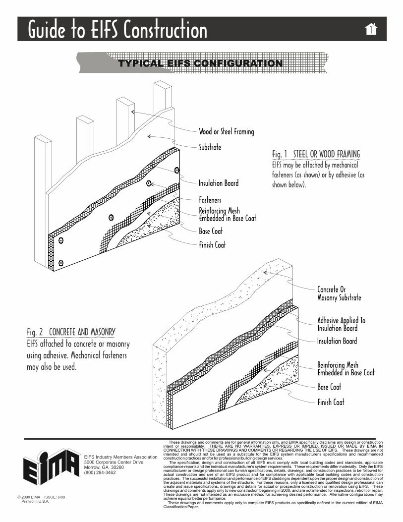
Fig. 2 CONCRETE AND MASONRYEIFS attached to concrete or masonryusing adhesive. Mechanical fastenersmay also be used.
Finish Coat
Reinforcing MeshEmbedded in Base Coat
Base Coat
Insulation Board
Adhesive Applied To
Concrete OrMasonry Substrate
Fig. 1 STEEL OR WOOD FRAMINGEIFS may be attached by mechanicalfasteners (as shown) or by adhesive (asshown below).
Fasteners
Insulation Board
Wood or Steel Framing
Reinforcing Mesh
Substrate
Base Coat
Embedded in Base Coat
Finish Coat
Insulation Board
2000 EIMA ISSUE: 6/00Printed in U.S.A.
These drawings and comments are for general information only, and EIMA specifically disclaims any design or constructionintent or responsibility. THERE ARE NO WARRANTIES, EXPRESS OR IMPLIED, ISSUED OR MADE BY EIMA INCONNECTION WITH THESE DRAWINGS AND COMMENTS OR REGARDING THE USE OF EIFS. These drawings are notintended and should not be used as a substitute for the EIFS system manufacturer's specifications and recommendedconstruction practices and/or for professional building design services.
The specification, design and construction of all EIFS must comply with local building codes and standards, applicablecompliance reports and the individual manufacturer's system requirements. These requirements differ materially. Only the EIFSmanufacturer or design professional can furnish specifications, details, drawings, and construction practices to be followed foractual construction and use of an EIFS product and for compliance with applicable local building codes and constructionpractices. The successful installation and performance of EIFS cladding is dependent upon the proper design and construction ofthe adjacent materials and systems of the structure. For these reasons, only a licensed and qualified design professional cancreate and issue specifications, drawings and details for actual or prospective construction or renovation using EIFS. Thesedrawings and comments apply only to new construction beginning in 2000, and are not intended for inspections, retrofit or repair.These drawings are not intended as an exclusive method for achieving desired performance. Alternative configurations mayachieve equal or better performance.
These drawings and comments apply only to complete EIFS products as specifically defined in the current edition of EIMAClassification Paper.
EIFS Industry Members Association3000 Corporate Center DriveMorrow, GA 30260(800) 294-3462
TYPICAL EIFS CONFIGURATION
Guide to EIFS ConstructionGuide to EIFS Construction 1

Insulation Board AppliedIn a Running Bond Pattern
Starter Row of Insulation
Board At CornersInterlock Edges of Insulation
Board Used to OffsetInsulation Board Joints From
Sheathing Board Joints
At Corners of WallInsulation Board “L” Cut
Penetrations
Encapsulate Insulation BoardEdge With Reinforcing Mesh
And Base Coat.
Strips of Reinforcing MeshPlaced Diagonally At
Opening Corners
Fig. 2 MESH TREATMENT AT FENESTRATIONTo further guard against cracking, diagonal pieces ofmesh called butterflies are placed over the wrappedmesh at corners of the opening.
Fig. 1 EPS BOARD LAYOUTThe Expanded Polystyrene Board (EPS) is placed on thewall in a running-bond pattern. The first row is generallyhalf width to minimize EPS board joints from lining upwith sheathing joints. To decrease base coat stress atcorners of wall openings, EPS boards are “L” cut.
Guide to EIFS ConstructionGuide to EIFS Construction 2
EPS BOARD LAYOUT
Window flashings, not shown,are placed at the head and sill.
NOTE:
2000 EIMA ISSUE: 6/00Printed in U.S.A.
These drawings and comments are for general information only, and EIMA specifically disclaims any design or constructionintent or responsibility. THERE ARE NO WARRANTIES, EXPRESS OR IMPLIED, ISSUED OR MADE BY EIMA INCONNECTION WITH THESE DRAWINGS AND COMMENTS OR REGARDING THE USE OF EIFS. These drawings are notintended and should not be used as a substitute for the EIFS system manufacturer's specifications and recommendedconstruction practices and/or for professional building design services.
The specification, design and construction of all EIFS must comply with local building codes and standards, applicablecompliance reports and the individual manufacturer's system requirements. These requirements differ materially. Only the EIFSmanufacturer or design professional can furnish specifications, details, drawings, and construction practices to be followed foractual construction and use of an EIFS product and for compliance with applicable local building codes and constructionpractices. The successful installation and performance of EIFS cladding is dependent upon the proper design and construction ofthe adjacent materials and systems of the structure. For these reasons, only a licensed and qualified design professional cancreate and issue specifications, drawings and details for actual or prospective construction or renovation using EIFS. Thesedrawings and comments apply only to new construction beginning in 2000, and are not intended for inspections, retrofit or repair.These drawings are not intended as an exclusive method for achieving desired performance. Alternative configurations mayachieve equal or better performance.
These drawings and comments apply only to complete EIFS products as specifically defined in the current edition of EIMAClassification Paper.
EIFS Industry Members Association3000 Corporate Center DriveMorrow, GA 30260(800) 294-3462
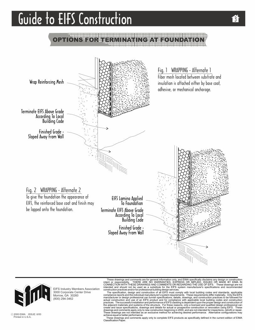
Wrap Reinforcing Mesh
Terminate EIFS Above GradeAccording To Local
Building Code
Finished Grade -Sloped Away From Wall
EIFS Lamina AppliedTo Foundation
Fig. 1 WRAPPING - Alternate 1Fiber mesh located between substrate andinsulation is attached either by base coat,adhesive, or mechanical anchorage.
Fig. 2 WRAPPING - Alternate 2To give the foundation the appearance ofEIFS, the reinforced base coat and finish maybe lapped onto the foundation. Terminate EIFS Above Grade
According To LocalBuilding Code
Finished Grade -Sloped Away From Wall
Guide to EIFS ConstructionGuide to EIFS Construction 3
OPTIONS FOR TERMINATING AT FOUNDATION
2000 EIMA ISSUE: 6/00Printed in U.S.A.
These drawings and comments are for general information only, and EIMA specifically disclaims any design or constructionintent or responsibility. THERE ARE NO WARRANTIES, EXPRESS OR IMPLIED, ISSUED OR MADE BY EIMA INCONNECTION WITH THESE DRAWINGS AND COMMENTS OR REGARDING THE USE OF EIFS. These drawings are notintended and should not be used as a substitute for the EIFS system manufacturer's specifications and recommendedconstruction practices and/or for professional building design services.
The specification, design and construction of all EIFS must comply with local building codes and standards, applicablecompliance reports and the individual manufacturer's system requirements. These requirements differ materially. Only the EIFSmanufacturer or design professional can furnish specifications, details, drawings, and construction practices to be followed foractual construction and use of an EIFS product and for compliance with applicable local building codes and constructionpractices. The successful installation and performance of EIFS cladding is dependent upon the proper design and construction ofthe adjacent materials and systems of the structure. For these reasons, only a licensed and qualified design professional cancreate and issue specifications, drawings and details for actual or prospective construction or renovation using EIFS. Thesedrawings and comments apply only to new construction beginning in 2000, and are not intended for inspections, retrofit or repair.These drawings are not intended as an exclusive method for achieving desired performance. Alternative configurations mayachieve equal or better performance.
These drawings and comments apply only to complete EIFS products as specifically defined in the current edition of EIMAClassification Paper.
EIFS Industry Members Association3000 Corporate Center DriveMorrow, GA 30260(800) 294-3462

Guide to EIFS ConstructionGuide to EIFS Construction 4
SEALANT CONFIGURATION OPTIONS
Fig. 1 FILLET JOINTFillet beads may be used for weather seal joints,such as at window and door perimeter. Note thatsealant is applied to the reinforced base coat andnot to the finish coat.
Fig. 2 BUTT JOINTExpansion joints should be designed for a minimumof four times the anticipated movement, but not lessthan 3/4” (19 mm). For joints where movement hasbeen determined to be negligible, the minimum buttjoint size is 1/2” (13 mm). Note that sealant isapplied to the reinforced base coat and not to thefinish coat.
TriangularBacker Rod
Insulation Board
Reinforcing MeshEmbedded InBase Coat
Embedded In Base Coat
Quarter Round Backer
Breaker Options Below)
Reinforcing Mesh
Bond Breaker Options
Bond BreakerTape
Sealant With ClosedCell Backer Rod
Fillet Joint
Rod (Refer to Bond
Insulation Board
Refer to the sealant manufacturer’s guidelinesfor specific installation requirements.
2000 EIMA ISSUE: 6/00Printed in U.S.A.
These drawings and comments are for general information only, and EIMA specifically disclaims any design or constructionintent or responsibility. THERE ARE NO WARRANTIES, EXPRESS OR IMPLIED, ISSUED OR MADE BY EIMA INCONNECTION WITH THESE DRAWINGS AND COMMENTS OR REGARDING THE USE OF EIFS. These drawings are notintended and should not be used as a substitute for the EIFS system manufacturer's specifications and recommendedconstruction practices and/or for professional building design services.
The specification, design and construction of all EIFS must comply with local building codes and standards, applicablecompliance reports and the individual manufacturer's system requirements. These requirements differ materially. Only the EIFSmanufacturer or design professional can furnish specifications, details, drawings, and construction practices to be followed foractual construction and use of an EIFS product and for compliance with applicable local building codes and constructionpractices. The successful installation and performance of EIFS cladding is dependent upon the proper design and construction ofthe adjacent materials and systems of the structure. For these reasons, only a licensed and qualified design professional cancreate and issue specifications, drawings and details for actual or prospective construction or renovation using EIFS. Thesedrawings and comments apply only to new construction beginning in 2000, and are not intended for inspections, retrofit or repair.These drawings are not intended as an exclusive method for achieving desired performance. Alternative configurations mayachieve equal or better performance.
These drawings and comments apply only to complete EIFS products as specifically defined in the current edition of EIMAClassification Paper.
EIFS Industry Members Association3000 Corporate Center DriveMorrow, GA 30260(800) 294-3462
Guide to EIFS ConstructionGuide to EIFS Construction 5
WINDOW - METAL FRAMED, EXPOSED SILL PAN
2000 EIMA ISSUE: 6/00Printed in U.S.A.
These drawings and comments are for general information only, and EIMA specifically disclaims any design or constructionintent or responsibility. THERE ARE NO WARRANTIES, EXPRESS OR IMPLIED, ISSUED OR MADE BY EIMA INCONNECTION WITH THESE DRAWINGS AND COMMENTS OR REGARDING THE USE OF EIFS. These drawings are notintended and should not be used as a substitute for the EIFS system manufacturer's specifications and recommendedconstruction practices and/or for professional building design services.
The specification, design and construction of all EIFS must comply with local building codes and standards, applicablecompliance reports and the individual manufacturer's system requirements. These requirements differ materially. Only the EIFSmanufacturer or design professional can furnish specifications, details, drawings, and construction practices to be followed foractual construction and use of an EIFS product and for compliance with applicable local building codes and constructionpractices. The successful installation and performance of EIFS cladding is dependent upon the proper design and construction ofthe adjacent materials and systems of the structure. For these reasons, only a licensed and qualified design professional cancreate and issue specifications, drawings and details for actual or prospective construction or renovation using EIFS. Thesedrawings and comments apply only to new construction beginning in 2000, and are not intended for inspections, retrofit or repair.These drawings are not intended as an exclusive method for achieving desired performance. Alternative configurations mayachieve equal or better performance.
These drawings and comments apply only to complete EIFS products as specifically defined in the current edition of EIMAClassification Paper.
EIFS Industry Members Association3000 Corporate Center DriveMorrow, GA 30260(800) 294-3462
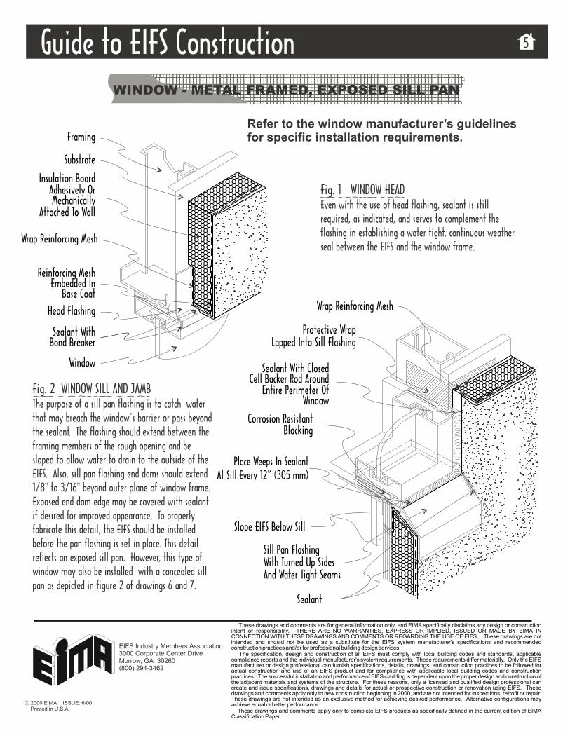
Fig. 1 WINDOW HEADEven with the use of head flashing, sealant is stillrequired, as indicated, and serves to complement theflashing in establishing a water tight, continuous weatherseal between the EIFS and the window frame.
Fig. 2 WINDOW SILL AND JAMBThe purpose of a sill pan flashing is to catch waterthat may breach the window’s barrier or pass beyondthe sealant. The flashing should extend between theframing members of the rough opening and besloped to allow water to drain to the outside of theEIFS. Also,
To properlyfabricate this detail, the EIFS should be installedbefore the pan flashing is set in place. This detailreflects an exposed sill pan. However, this type ofwindow may also be installed with a concealed sillpan as depicted in figure 2 of drawings 6 and 7.
sill pan flashing end dams should extend1/8" to 3/16" beyond outer plane of window frame.Exposed end dam edge may be covered with sealantif desired for improved appearance.
Framing
Substrate
Insulation BoardAdhesively OrMechanically
Attached To Wall
Wrap Reinforcing Mesh
Reinforcing MeshEmbedded In
Head Flashing
Sealant WithBond Breaker
Window
Base Coat
Sill Pan FlashingWith Turned Up SidesAnd Water Tight Seams
Slope EIFS Below Sill
Sealant With ClosedCell Backer Rod Around
Place Weeps In SealantAt Sill Every 12” (305 mm)
Sealant
Entire Perimeter OfWindow
Corrosion ResistantBlocking
Wrap Reinforcing Mesh
Protective WrapLapped Into Sill Flashing
Refer to the window manufacturer’s guidelinesfor specific installation requirements.
Guide to EIFS ConstructionGuide to EIFS Construction 6
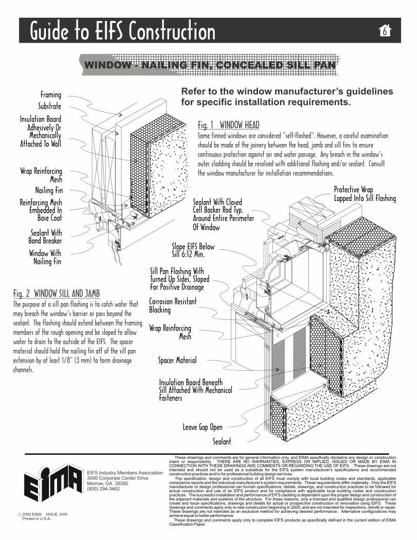
WINDOW - NAILING FIN, CONCEALED SILL PAN
Fig. 1 WINDOW HEADSome finned windows are considered “self-flashed”. However, a careful examinationshould be made of the joinery between the head, jamb and sill fins to ensurecontinuous protection against air and water passage. Any breach in the window’souter cladding should be resolved with additional flashing and/or sealant. Consultthe window manufacturer for installation recommendations.
Fig. 2 WINDOW SILL AND JAMBThe purpose of a sill pan flashing is to catch water thatmay breach the window’s barrier or pass beyond thesealant. The flashing should extend between the framingmembers of the rough opening and be sloped to allowwater to drain to the outside of the EIFS. The spacermaterial should hold the nailing fin off of the sill panextension by at least 1/8” (3 mm) to form drainagechannels.
Framing
Substrate
Insulation BoardAdhesively OrMechanically
Attached To Wall
Wrap ReinforcingMesh
Reinforcing MeshEmbedded In
Sealant WithBond Breaker
Window WithNailing Fin
Base Coat
Nailing Fin
Sill Pan Flashing WithTurned Up Sides, SlopedFor Positive Drainage
Slope EIFS BelowSill 6:12 Min.
Sealant With ClosedCell Backer Rod Typ.
Spacer Material
Around Entire PerimeterOf Window
Insulation Board BeneathSill Attached With MechanicalFasteners
Sealant
Leave Gap Open
Corrosion ResistantBlocking
Refer to the window manufacturer’s guidelinesfor specific installation requirements.
Wrap ReinforcingMesh
Protective WrapLapped Into Sill Flashing
2000 EIMA ISSUE: 6/00Printed in U.S.A.
These drawings and comments are for general information only, and EIMA specifically disclaims any design or constructionintent or responsibility. THERE ARE NO WARRANTIES, EXPRESS OR IMPLIED, ISSUED OR MADE BY EIMA INCONNECTION WITH THESE DRAWINGS AND COMMENTS OR REGARDING THE USE OF EIFS. These drawings are notintended and should not be used as a substitute for the EIFS system manufacturer's specifications and recommendedconstruction practices and/or for professional building design services.
The specification, design and construction of all EIFS must comply with local building codes and standards, applicablecompliance reports and the individual manufacturer's system requirements. These requirements differ materially. Only the EIFSmanufacturer or design professional can furnish specifications, details, drawings, and construction practices to be followed foractual construction and use of an EIFS product and for compliance with applicable local building codes and constructionpractices. The successful installation and performance of EIFS cladding is dependent upon the proper design and construction ofthe adjacent materials and systems of the structure. For these reasons, only a licensed and qualified design professional cancreate and issue specifications, drawings and details for actual or prospective construction or renovation using EIFS. Thesedrawings and comments apply only to new construction beginning in 2000, and are not intended for inspections, retrofit or repair.These drawings are not intended as an exclusive method for achieving desired performance. Alternative configurations mayachieve equal or better performance.
These drawings and comments apply only to complete EIFS products as specifically defined in the current edition of EIMAClassification Paper.
EIFS Industry Members Association3000 Corporate Center DriveMorrow, GA 30260(800) 294-3462

Guide to EIFS ConstructionGuide to EIFS Construction 7
WINDOW - BRICK MOLD, CONCEALED SILL PAN
Fig. 2 WINDOW SILL AND JAMBThe purpose of a sill pan flashing is to catchwater that may breach the window’s barrier orpass beyond the sealant. The flashing shouldextend between the framing members of therough opening and be sloped to allow water todrain to the outside of the EIFS. The drainagemedium should hold the EPS insulation board offof the sill pan extension by at least 1/8” (3mm). This detail depicts a concealed sill pan.However, this type of window may also beinstalled with an exposed sill pan as depicted infigure 2 of drawing 5.
Framing
Substrate
Insulation BoardAdhesively OrMechanically
Attached To Wall
Wrap ReinforcingMesh
Reinforcing MeshEmbedded In
Sealant With ClosedCell Backer Rod
Window WithBrick Mold
Base Coat
Head Flashing
Sill Pan Flashing WithTurned Up Sides AndWater Tight Seams
Slope EIFS ForDrainage
Sealant With ClosedCell Backer Rod Typ.
Drainage Medium
Around Entire PerimeterOf Window
Insulation Board BeneathSill Attached With MecahnicalFasteners
Sealant
Leave Gap Open
Sealant
Corrosion ResistantBlocking
Refer to the window manufacturer’s guidelines forspecific installation requirements.
Protective Wrap LappedInto Sill Pan Flashing
Fig. 1 WINDOW HEADEven with the use of head flashing, sealant is still required, as indicated,and serves to complement the flashing in establishing a water tight,continuous weather seal between the EIFS and the window frame.
Wrap ReinforcingMesh
Wrap Reinforcing Mesh
2000 EIMA ISSUE: 6/00Printed in U.S.A.
These drawings and comments are for general information only, and EIMA specifically disclaims any design or constructionintent or responsibility. THERE ARE NO WARRANTIES, EXPRESS OR IMPLIED, ISSUED OR MADE BY EIMA INCONNECTION WITH THESE DRAWINGS AND COMMENTS OR REGARDING THE USE OF EIFS. These drawings are notintended and should not be used as a substitute for the EIFS system manufacturer's specifications and recommendedconstruction practices and/or for professional building design services.
The specification, design and construction of all EIFS must comply with local building codes and standards, applicablecompliance reports and the individual manufacturer's system requirements. These requirements differ materially. Only the EIFSmanufacturer or design professional can furnish specifications, details, drawings, and construction practices to be followed foractual construction and use of an EIFS product and for compliance with applicable local building codes and constructionpractices. The successful installation and performance of EIFS cladding is dependent upon the proper design and construction ofthe adjacent materials and systems of the structure. For these reasons, only a licensed and qualified design professional cancreate and issue specifications, drawings and details for actual or prospective construction or renovation using EIFS. Thesedrawings and comments apply only to new construction beginning in 2000, and are not intended for inspections, retrofit or repair.These drawings are not intended as an exclusive method for achieving desired performance. Alternative configurations mayachieve equal or better performance.
These drawings and comments apply only to complete EIFS products as specifically defined in the current edition of EIMAClassification Paper.
EIFS Industry Members Association3000 Corporate Center DriveMorrow, GA 30260(800) 294-3462

Fig. 1 HOSE BIBB ATTACHMENTFor accessories subjected to handling, such as hosebibs and railing supports, wood blocking offersprotection to the EIFS while providing a base for rigidattachment. The wood blocking may be painted orencapsulated in flashing.
Fig. 2 ELECTRICAL ATTACHMENTElectrical box installations, whether for light fixturesor outlets, may be shimmed back to the sheathingto allow for flush mounting of the electricalaccessory.
EIFS Finish Coat
Decay and CorrosionResistant BlockingPainted Or Flashed
For Protection
Hose Bibb
Cell Backer RodSealant with Closed
Substrate
Fixture
Insulation BoardAdhesively orMechanically
Attached To Wall
Sealant with Closed
Wrap Reinforcing Mesh
EIFS Finish Coat
Cell Backer Rod
Sealant In FilletConfiguration
Seal Fixture ToFace of EIFS
Guide to EIFS ConstructionGuide to EIFS Construction 8
PLUMBING AND ELECTRICAL PENETRATIONS
2000 EIMA ISSUE: 6/00Printed in U.S.A.
These drawings and comments are for general information only, and EIMA specifically disclaims any design or constructionintent or responsibility. THERE ARE NO WARRANTIES, EXPRESS OR IMPLIED, ISSUED OR MADE BY EIMA INCONNECTION WITH THESE DRAWINGS AND COMMENTS OR REGARDING THE USE OF EIFS. These drawings are notintended and should not be used as a substitute for the EIFS system manufacturer's specifications and recommendedconstruction practices and/or for professional building design services.
The specification, design and construction of all EIFS must comply with local building codes and standards, applicablecompliance reports and the individual manufacturer's system requirements. These requirements differ materially. Only the EIFSmanufacturer or design professional can furnish specifications, details, drawings, and construction practices to be followed foractual construction and use of an EIFS product and for compliance with applicable local building codes and constructionpractices. The successful installation and performance of EIFS cladding is dependent upon the proper design and construction ofthe adjacent materials and systems of the structure. For these reasons, only a licensed and qualified design professional cancreate and issue specifications, drawings and details for actual or prospective construction or renovation using EIFS. Thesedrawings and comments apply only to new construction beginning in 2000, and are not intended for inspections, retrofit or repair.These drawings are not intended as an exclusive method for achieving desired performance. Alternative configurations mayachieve equal or better performance.
These drawings and comments apply only to complete EIFS products as specifically defined in the current edition of EIMAClassification Paper.
EIFS Industry Members Association3000 Corporate Center DriveMorrow, GA 30260(800) 294-3462
Guide to EIFS ConstructionGuide to EIFS Construction 9
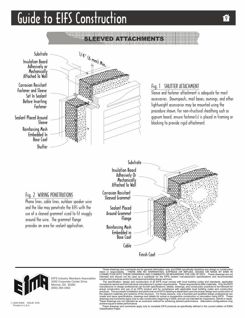
SLEEVED ATTACHMENTS
Finish Coat
Fig. 1 SHUTTER ATTACHMENTSleeve and fastener attachment is adequate for mostaccessories. Downspouts, mail boxes, awnings, and otherlightweight accessories may be mounted using theprocedure shown. For non-structural sheathing such asgypsum board, ensure fastener(s) is placed in framing orblocking to provide rigid attachment.
Fig. 2 WIRING PENETRATIONSPhone lines, cable lines, outdoor speaker wireand the like may penetrate the EIFS with theuse of a sleeved grommet sized to fit snugglyaround the wire. The grommet flangeprovides an area for sealant application.
Corrosion ResistantFastener and Sleeve
Reinforcing MeshEmbedded In
SleeveSealant Placed Around
Substrate
Before InsertingSet In Sealant
Shutter
Sleeved Grommet
Cable
Sealant PlacedAround Grommet
Embedded inReinforcing Mesh
Substrate
Corrosion Resistant
Insulation BoardAdhesively OrMechanically
Attached To Wall
Fastener
Base Coat
Flange
Base Coat
1/4” (6 mm) Min.Insulation Board
Adhesively orMechanically
Attached To Wall
2000 EIMA ISSUE: 6/00Printed in U.S.A.
These drawings and comments are for general information only, and EIMA specifically disclaims any design or constructionintent or responsibility. THERE ARE NO WARRANTIES, EXPRESS OR IMPLIED, ISSUED OR MADE BY EIMA INCONNECTION WITH THESE DRAWINGS AND COMMENTS OR REGARDING THE USE OF EIFS. These drawings are notintended and should not be used as a substitute for the EIFS system manufacturer's specifications and recommendedconstruction practices and/or for professional building design services.
The specification, design and construction of all EIFS must comply with local building codes and standards, applicablecompliance reports and the individual manufacturer's system requirements. These requirements differ materially. Only the EIFSmanufacturer or design professional can furnish specifications, details, drawings, and construction practices to be followed foractual construction and use of an EIFS product and for compliance with applicable local building codes and constructionpractices. The successful installation and performance of EIFS cladding is dependent upon the proper design and construction ofthe adjacent materials and systems of the structure. For these reasons, only a licensed and qualified design professional cancreate and issue specifications, drawings and details for actual or prospective construction or renovation using EIFS. Thesedrawings and comments apply only to new construction beginning in 2000, and are not intended for inspections, retrofit or repair.These drawings are not intended as an exclusive method for achieving desired performance. Alternative configurations mayachieve equal or better performance.
These drawings and comments apply only to complete EIFS products as specifically defined in the current edition of EIMAClassification Paper.
EIFS Industry Members Association3000 Corporate Center DriveMorrow, GA 30260(800) 294-3462
Guide to EIFS ConstructionGuide to EIFS Construction 10
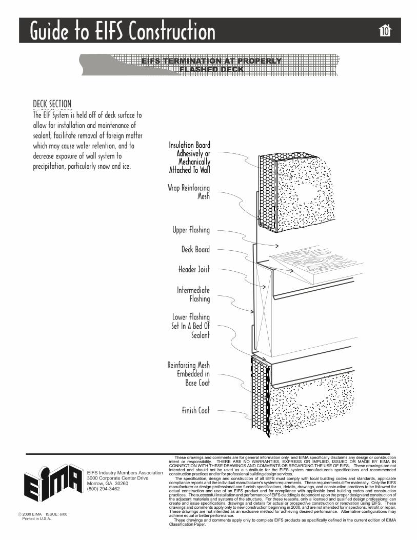
EIFS TERMINATION AT PROPERLY
FLASHED DECK
Wrap ReinforcingMesh
Upper Flashing
Deck Board
Header Joist
Intermediate
Lower FlashingSet In A Bed Of
Sealant
Reinforcing Mesh
Finish Coat
Embedded in
Flashing
Base Coat
Insulation BoardAdhesively orMechanically
Attached To Wall
DECK SECTIONThe EIF System is held off of deck surface to
facilitate removal of foreign matterwhich may cause water retention, and todecrease exposure of wall system toprecipitation, particularly snow and ice.
allow for installation and maintenance ofsealant,
2000 EIMA ISSUE: 6/00Printed in U.S.A.
These drawings and comments are for general information only, and EIMA specifically disclaims any design or constructionintent or responsibility. THERE ARE NO WARRANTIES, EXPRESS OR IMPLIED, ISSUED OR MADE BY EIMA INCONNECTION WITH THESE DRAWINGS AND COMMENTS OR REGARDING THE USE OF EIFS. These drawings are notintended and should not be used as a substitute for the EIFS system manufacturer's specifications and recommendedconstruction practices and/or for professional building design services.
The specification, design and construction of all EIFS must comply with local building codes and standards, applicablecompliance reports and the individual manufacturer's system requirements. These requirements differ materially. Only the EIFSmanufacturer or design professional can furnish specifications, details, drawings, and construction practices to be followed foractual construction and use of an EIFS product and for compliance with applicable local building codes and constructionpractices. The successful installation and performance of EIFS cladding is dependent upon the proper design and construction ofthe adjacent materials and systems of the structure. For these reasons, only a licensed and qualified design professional cancreate and issue specifications, drawings and details for actual or prospective construction or renovation using EIFS. Thesedrawings and comments apply only to new construction beginning in 2000, and are not intended for inspections, retrofit or repair.These drawings are not intended as an exclusive method for achieving desired performance. Alternative configurations mayachieve equal or better performance.
These drawings and comments apply only to complete EIFS products as specifically defined in the current edition of EIMAClassification Paper.
EIFS Industry Members Association3000 Corporate Center DriveMorrow, GA 30260(800) 294-3462
Guide to EIFS ConstructionGuide to EIFS Construction 11
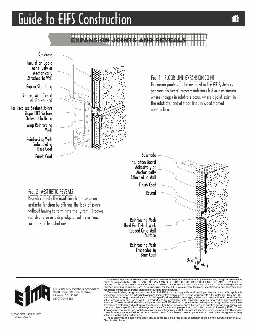
EXPANSION JOINTS AND REVEALS
Fig. 1 FLOOR LINE EXPANSION JOINTExpansion joints shall be installed in the EIF System asper manufacturers’ recommendations but as a minimumwhere changes in substrate occur, where a joint exists inthe substrate, and at floor lines in wood framedconstruction.
Fig. 2 AESTHETIC REVEALSReveals cut into the insulation board serve anaesthetic function by offering the look of jointswithout having to terminate the system. Groovescan also serve as a drip edge at soffits or headlocations of fenestrations.
Substrate
Wrap ReinforcingMesh
Sealant With Closed
Gap in Sheathing
Cell Backer Rod
Reinforcing MeshEmbedded in
Finish Coat
Base Coat
For Recessed Sealant JointsSlope EIFS SurfaceOutward To Drain
Substrate
Reinforcing MeshUsed For Detail Work
Finish Coat
Base CoatEmbedded in
Reinforcing Mesh
Reveal
SurfaceLapped Onto Wall
3/4" (19 mm)Min.
Insulation BoardAdhesively orMechanically
Attached To Wall
Insulation BoardAdhesively orMechanically
Attached To Wall
2000 EIMA ISSUE: 6/00Printed in U.S.A.
These drawings and comments are for general information only, and EIMA specifically disclaims any design or constructionintent or responsibility. THERE ARE NO WARRANTIES, EXPRESS OR IMPLIED, ISSUED OR MADE BY EIMA INCONNECTION WITH THESE DRAWINGS AND COMMENTS OR REGARDING THE USE OF EIFS. These drawings are notintended and should not be used as a substitute for the EIFS system manufacturer's specifications and recommendedconstruction practices and/or for professional building design services.
The specification, design and construction of all EIFS must comply with local building codes and standards, applicablecompliance reports and the individual manufacturer's system requirements. These requirements differ materially. Only the EIFSmanufacturer or design professional can furnish specifications, details, drawings, and construction practices to be followed foractual construction and use of an EIFS product and for compliance with applicable local building codes and constructionpractices. The successful installation and performance of EIFS cladding is dependent upon the proper design and construction ofthe adjacent materials and systems of the structure. For these reasons, only a licensed and qualified design professional cancreate and issue specifications, drawings and details for actual or prospective construction or renovation using EIFS. Thesedrawings and comments apply only to new construction beginning in 2000, and are not intended for inspections, retrofit or repair.These drawings are not intended as an exclusive method for achieving desired performance. Alternative configurations mayachieve equal or better performance.
These drawings and comments apply only to complete EIFS products as specifically defined in the current edition of EIMAClassification Paper.
EIFS Industry Members Association3000 Corporate Center DriveMorrow, GA 30260(800) 294-3462
Guide to EIFS ConstructionGuide to EIFS Construction 12
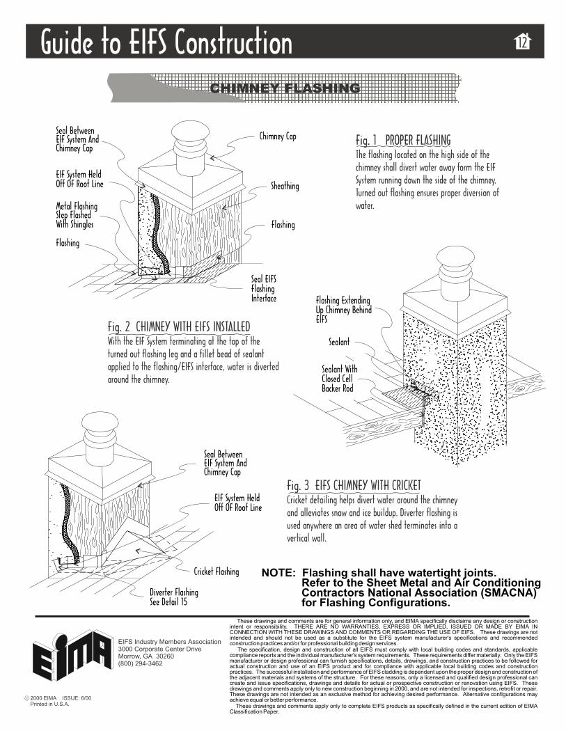
CHIMNEY FLASHING
Fig. 1 PROPER FLASHINGThe flashing located on the high side of thechimney shall divert water away form the EIFSystem running down the side of the chimney.Turned out flashing ensures proper diversion ofwater.
Fig. 3 EIFS CHIMNEY WITH CRICKETCricket detailing helps divert water around the chimneyand alleviates snow and ice buildup. Diverter flashing isused anywhere an area of water shed terminates into avertical wall.
Sealant WithClosed CellBacker Rod
Sealant
With Shingles
Metal FlashingStep Flashed
Flashing
Flashing
Seal EIFSFlashingInterface
Chimney Cap
Sheathing
Seal BetweenEIF System AndChimney Cap
Flashing ExtendingUp Chimney BehindEIFS
EIF System HeldOff OF Roof Line
Diverter FlashingSee Detail 15
Cricket Flashing
Seal BetweenEIF System AndChimney Cap
Fig. 2 CHIMNEY WITH EIFS INSTALLEDWith the EIF System terminating at the top of theturned out flashing leg and a fillet bead of sealantapplied to the flashing/EIFS interface, water is divertedaround the chimney.
NOTE: Flashing shall have watertight joints.Refer to the Sheet Metal and Air ConditioningContractors National Association (SMACNA)for Flashing Configurations.
EIF System HeldOff OF Roof Line
2000 EIMA ISSUE: 6/00Printed in U.S.A.
These drawings and comments are for general information only, and EIMA specifically disclaims any design or constructionintent or responsibility. THERE ARE NO WARRANTIES, EXPRESS OR IMPLIED, ISSUED OR MADE BY EIMA INCONNECTION WITH THESE DRAWINGS AND COMMENTS OR REGARDING THE USE OF EIFS. These drawings are notintended and should not be used as a substitute for the EIFS system manufacturer's specifications and recommendedconstruction practices and/or for professional building design services.
The specification, design and construction of all EIFS must comply with local building codes and standards, applicablecompliance reports and the individual manufacturer's system requirements. These requirements differ materially. Only the EIFSmanufacturer or design professional can furnish specifications, details, drawings, and construction practices to be followed foractual construction and use of an EIFS product and for compliance with applicable local building codes and constructionpractices. The successful installation and performance of EIFS cladding is dependent upon the proper design and construction ofthe adjacent materials and systems of the structure. For these reasons, only a licensed and qualified design professional cancreate and issue specifications, drawings and details for actual or prospective construction or renovation using EIFS. Thesedrawings and comments apply only to new construction beginning in 2000, and are not intended for inspections, retrofit or repair.These drawings are not intended as an exclusive method for achieving desired performance. Alternative configurations mayachieve equal or better performance.
These drawings and comments apply only to complete EIFS products as specifically defined in the current edition of EIMAClassification Paper.
EIFS Industry Members Association3000 Corporate Center DriveMorrow, GA 30260(800) 294-3462
Guide to EIFS ConstructionGuide to EIFS Construction 13
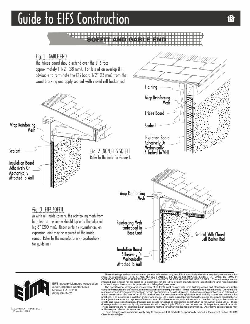
SOFFIT AND GABLE END
2000 EIMA ISSUE: 6/00Printed in U.S.A.
These drawings and comments are for general information only, and EIMA specifically disclaims any design or constructionintent or responsibility. THERE ARE NO WARRANTIES, EXPRESS OR IMPLIED, ISSUED OR MADE BY EIMA INCONNECTION WITH THESE DRAWINGS AND COMMENTS OR REGARDING THE USE OF EIFS. These drawings are notintended and should not be used as a substitute for the EIFS system manufacturer's specifications and recommendedconstruction practices and/or for professional building design services.
The specification, design and construction of all EIFS must comply with local building codes and standards, applicablecompliance reports and the individual manufacturer's system requirements. These requirements differ materially. Only the EIFSmanufacturer or design professional can furnish specifications, details, drawings, and construction practices to be followed foractual construction and use of an EIFS product and for compliance with applicable local building codes and constructionpractices. The successful installation and performance of EIFS cladding is dependent upon the proper design and construction ofthe adjacent materials and systems of the structure. For these reasons, only a licensed and qualified design professional cancreate and issue specifications, drawings and details for actual or prospective construction or renovation using EIFS. Thesedrawings and comments apply only to new construction beginning in 2000, and are not intended for inspections, retrofit or repair.These drawings are not intended as an exclusive method for achieving desired performance. Alternative configurations mayachieve equal or better performance.
These drawings and comments apply only to complete EIFS products as specifically defined in the current edition of EIMAClassification Paper.
EIFS Industry Members Association3000 Corporate Center DriveMorrow, GA 30260(800) 294-3462
Fig. 1 GABLE ENDThe frieze board should extend over the EIFS faceapproximately 1 1/2” (38 mm). For less of an overlap it isadvisable to terminate the EPS board 1/2” (13 mm) from thewood blocking and apply sealant with closed cell backer rod.
Fig. 2 NON EIFS SOFFITRefer to the note for Figure 1.
Sealant
Insulation BoardAdhesively OrMechanically
Attached To Wall
Sealant With ClosedCell Backer Rod
Reinforcing MeshEmbedded In
Base Coat
Insulation BoardAdhesively OrMechanicallyAttached To Wall
Sealant
Flashing
Wrap ReinforcingMesh
Insulation BoardAdhesively OrMechanicallyAttached To Wall
Frieze Board
Fig. 3 EIFS SOFFITAs with all inside corners, the reinforcing mesh fromboth legs of the corner should lap onto the adjacentleg 8” (200 mm). Under certain circumstances, anexpansion joint may be required at the insidecorner. Refer to the manufacturer’s specificationsfor guidelines.
Wrap ReinforcingMesh
Wrap ReinforcingMesh
Guide to EIFS ConstructionGuide to EIFS Construction 14
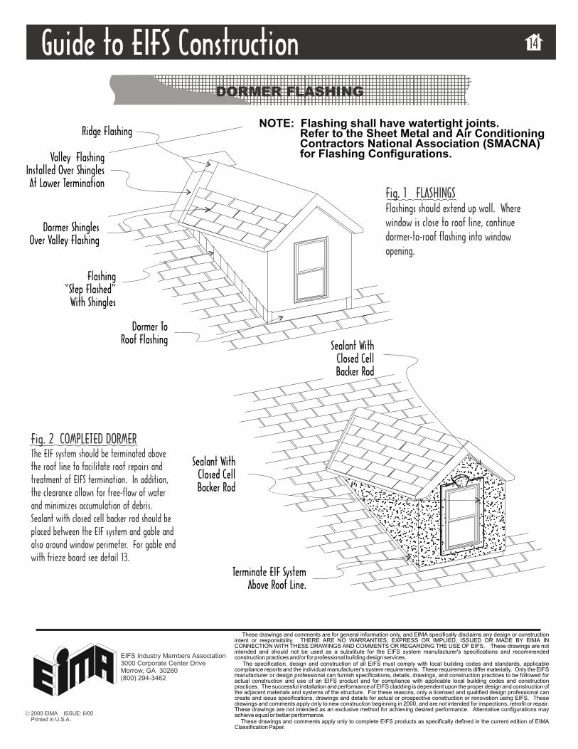
DORMER FLASHING
2000 EIMA ISSUE: 6/00Printed in U.S.A.
These drawings and comments are for general information only, and EIMA specifically disclaims any design or constructionintent or responsibility. THERE ARE NO WARRANTIES, EXPRESS OR IMPLIED, ISSUED OR MADE BY EIMA INCONNECTION WITH THESE DRAWINGS AND COMMENTS OR REGARDING THE USE OF EIFS. These drawings are notintended and should not be used as a substitute for the EIFS system manufacturer's specifications and recommendedconstruction practices and/or for professional building design services.
The specification, design and construction of all EIFS must comply with local building codes and standards, applicablecompliance reports and the individual manufacturer's system requirements. These requirements differ materially. Only the EIFSmanufacturer or design professional can furnish specifications, details, drawings, and construction practices to be followed foractual construction and use of an EIFS product and for compliance with applicable local building codes and constructionpractices. The successful installation and performance of EIFS cladding is dependent upon the proper design and construction ofthe adjacent materials and systems of the structure. For these reasons, only a licensed and qualified design professional cancreate and issue specifications, drawings and details for actual or prospective construction or renovation using EIFS. Thesedrawings and comments apply only to new construction beginning in 2000, and are not intended for inspections, retrofit or repair.These drawings are not intended as an exclusive method for achieving desired performance. Alternative configurations mayachieve equal or better performance.
These drawings and comments apply only to complete EIFS products as specifically defined in the current edition of EIMAClassification Paper.
EIFS Industry Members Association3000 Corporate Center DriveMorrow, GA 30260(800) 294-3462
Fig. 1 FLASHINGSFlashings should extend up wall. Wherewindow is close to roof line, continuedormer-to-roof flashing into windowopening.
Fig. 2 COMPLETED DORMERThe EIF system should be terminated abovethe roof line to facilitate roof repairs andtreatment of EIFS termination. In addition,the clearance allows for free-flow of waterand minimizes accumulation of debris.Sealant with closed cell backer rod should beplaced between the EIF system and gable andalso around window perimeter. For gable endwith frieze board see detail 13.
Valley FlashingInstalled Over ShinglesAt Lower Termination
Dormer ToRoof Flashing
Dormer ShinglesOver Valley Flashing
Flashing“Step Flashed”
With Shingles
Ridge Flashing
Sealant WithClosed CellBacker Rod
Sealant WithClosed CellBacker Rod
Terminate EIF SystemAbove Roof Line.
NOTE: Flashing shall have watertight joints.Refer to the Sheet Metal and Air ConditioningContractors National Association (SMACNA)for Flashing Configurations.
Guide to EIFS ConstructionGuide to EIFS Construction 15
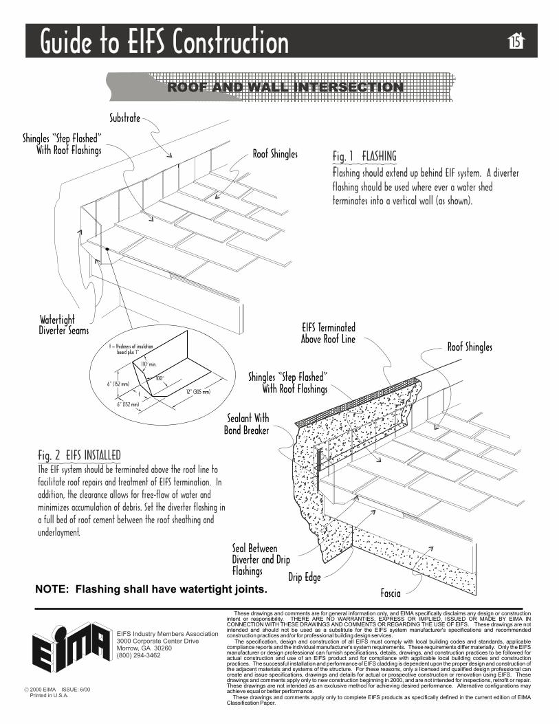
ROOF AND WALL INTERSECTION
t = thickness of insulationboard plus 1”
Fig. 1 FLASHINGFlashing should extend up behind EIF system. A diverterflashing should be used where ever a water shedterminates into a vertical wall (as shown).
Fig. 2 EIFS INSTALLEDThe EIF system should be terminated above the roof line tofacilitate roof repairs and treatment of EIFS termination. Inaddition, the clearance allows for free-flow of water andminimizes accumulation of debris. Set the diverter flashing ina full bed of roof cement between the roof sheathing andunderlayment.
Sealant WithBond Breaker
Shingles “Step Flashed”With Roof Flashings
Shingles “Step Flashed”With Roof Flashings
EIFS TerminatedAbove Roof Line
Roof Shingles
Fascia
Diverter SeamsWatertight
Roof Shingles
Drip Edge
6” (152 mm)
6” (152 mm)
Substrate
12” (305 mm)t
100
110 min.
NOTE: Flashing shall have watertight joints.
Seal BetweenDiverter and DripFlashings
2000 EIMA ISSUE: 6/00Printed in U.S.A.
These drawings and comments are for general information only, and EIMA specifically disclaims any design or constructionintent or responsibility. THERE ARE NO WARRANTIES, EXPRESS OR IMPLIED, ISSUED OR MADE BY EIMA INCONNECTION WITH THESE DRAWINGS AND COMMENTS OR REGARDING THE USE OF EIFS. These drawings are notintended and should not be used as a substitute for the EIFS system manufacturer's specifications and recommendedconstruction practices and/or for professional building design services.
The specification, design and construction of all EIFS must comply with local building codes and standards, applicablecompliance reports and the individual manufacturer's system requirements. These requirements differ materially. Only the EIFSmanufacturer or design professional can furnish specifications, details, drawings, and construction practices to be followed foractual construction and use of an EIFS product and for compliance with applicable local building codes and constructionpractices. The successful installation and performance of EIFS cladding is dependent upon the proper design and construction ofthe adjacent materials and systems of the structure. For these reasons, only a licensed and qualified design professional cancreate and issue specifications, drawings and details for actual or prospective construction or renovation using EIFS. Thesedrawings and comments apply only to new construction beginning in 2000, and are not intended for inspections, retrofit or repair.These drawings are not intended as an exclusive method for achieving desired performance. Alternative configurations mayachieve equal or better performance.
These drawings and comments apply only to complete EIFS products as specifically defined in the current edition of EIMAClassification Paper.
EIFS Industry Members Association3000 Corporate Center DriveMorrow, GA 30260(800) 294-3462