
Guide to Dual Flight Operations - National Weather … html/Performing Dual Radiosonde...Guide to...
12
Guide to Dual Flight Operations Preparing & Releasing a Dual Flight Bar Vaisala RS92-NGP ® Sippican B2 ® Upper Air Data Continuity Study -DRAFT- Prepared by Sterling Field Support Center U.S. DEPARTMENT OF COMMERCE National Oceanic and Atmospheric Administration National Weather Service/Office of Operational Systems Field Systems Operations Center/Observing Systems Branch
Transcript of Guide to Dual Flight Operations - National Weather … html/Performing Dual Radiosonde...Guide to...
Guide to Dual Flight Operations Preparing & Releasing a Dual Flight Bar
Vaisala RS92-NGP® Sippican B2®
Upper Air Data Continuity Study
-DRAFT-
Prepared by
Sterling Field Support Center
U.S. DEPARTMENT OF COMMERCE
National Oceanic and Atmospheric Administration
National Weather Service/Office of Operational Systems
Field Systems Operations Center/Observing Systems Branch

ACRONYMS AND ABBREVIATIONS
TERMS DEFINITION
BILS Balloon Inflation Launch Shelter
CDU Control Display Unit:
GPS Global Positioning System
hPa. Hectopascal
IF Intermediate Frequency
KHz Kilohertz
LOS Line-Of-Sight
Mb Millibar
PSI Pounds Per Square Inch
IB Inflation Building
MHz Megahertz
MSL Mean Sea Level
NCDC National Climatic Data Center
NEC National Electrical Code
NFPA National Fire Protection Association
NOTAM Notice to Airman
PITS Protocol Interface Tests Suite
RF Radio Frequency
RRS Radiosonde Replacement System
RSOIS Radiosonde Surface Observing Instrument System
RWS RRS Workstation
SDM Station Duty Manual
SPS Signal Processing System
SPSS Statistical Package for the Social Sciences
TRS Telemetry Receiving System
UHF Ultra High Frequency
UPS Uninterruptible Power Source
UTC Universal Time Code
WMO World Meteorological Organization
1.0 Introduction
The Upper Air Data Continuity Study (DCS) is useful for investigating the relationship between
climate variation and change due to measurement error. To replace the antiquated
Microcomputer Automatic Radio-theodolite (MicroART), a system that has been in operation
since the late 1980s, new Global Positioning System (GPS) radiosondes are being introduced.
The NWS upper air network has witnessed a significant impact on operations from the
implementation of these new GPS radiosondes due to sensor changes for temperature, pressure
and relative humidity measurements. Because these have differing characteristics than other
current radiosondes, the Data Continuity Study is pertinent in assessing the sensors in a variety
of climatic and meteorological conditions.
The Data Continuity Study flight configuration will consist of flying two radiosondes on the
same balloon during the 00z and 12z synoptic windows one day a week. The day that flights will
occur will be left up to the site’s discretion; however, once DCS flights begin, the site will
continue with that scheduled day. These flights must be conducted as precisely as possible in
order to accurately assess the sensors’ behavior. The purpose of this document is therefore to
guide observers through the steps to properly assemble and release a dual flight bar in order to
complete an accurate and successful flight using the Vaisala RS92-NGP and Sippican B2
radiosondes.
2.0 Procedures
The following procedures detail the prescribed order of operations to be conducted when
performing a dual flight. More specific instructions can be found in the Guide to Dual Flight
Operations Performance Checklist.
1.) Equipment Warm-Up
Powering on UPS and other hardware to allow for warm-up operations
2.) Balloon Inflation and Train Assembly
Preparing balloon and train assembly for flight
3.) Radiosonde Preparation
Preparing radiosondes according to vendor documentation
4.) Ground Equipment Preparation Procedures
Completing hardware status checks, pre-observation information, instrument
baseline and antenna positioning
5.) Release Site Processes
Final train preparations, obtaining launch approval, and possible repositioning of
antenna
6.) In-Flight Procedures
Ensuring release was detected, monitoring the flight using displays and plots,
transmitting messages
7.) Archiving Flights
Uploading compressed flight data to FTP site for NCDC

3.0 Instructions for Balloon Inflation and Train Assembly
Pre-observation procedures are an important component in successful upper-air operations. The
care taken in preparing for an observation decreases the likelihood of having an unsuccessful or
missed observation due defective parts or from using improper procedures. The observer should
be aware of changing weather conditions that may affect the decision on train components used
for the flight, the amount of gas, and release obstacles that may result from such conditions.
Begin inflating an HM-32 Balloon
Determine the additional weight needed for the dual flight depending on the
present weather conditions and those expected at the time of release. The
following chart can assist in determining this weight based on the prevailing
weather type and intensity:
Precipitation Frozen Precipitation
Intensity Additional Weight (g) Intensity Additional Weight (g)
Light Rain 1100-1300 g Light Frozen 1200-1400 g
Moderate Rain 1300-1500 g Moderate Frozen 1400-1500 g
Heavy Rain 1500-1800 g Heavy Frozen 1700-1900 g
No Precipitation: 800-1000 g
* Use this table as a guideline for applying additional weight since ranges are heavily
dependent upon location, temperature variations, and balloon manufacturing
procedures. It is important to monitor the flight to ensure SFC-Term ascent rates of
250-350 m/min are being achieved.*
To prepare the train using two parachutes, first tie a 7 foot length of double strand
cord to the top of the first parachute, leaving free the other end. Repeat this step
again, except tying the cord to the top of the second parachute. This cord should
then be knotted securely to the bottom of the first parachute.
Figure 1. Tying parachutes together
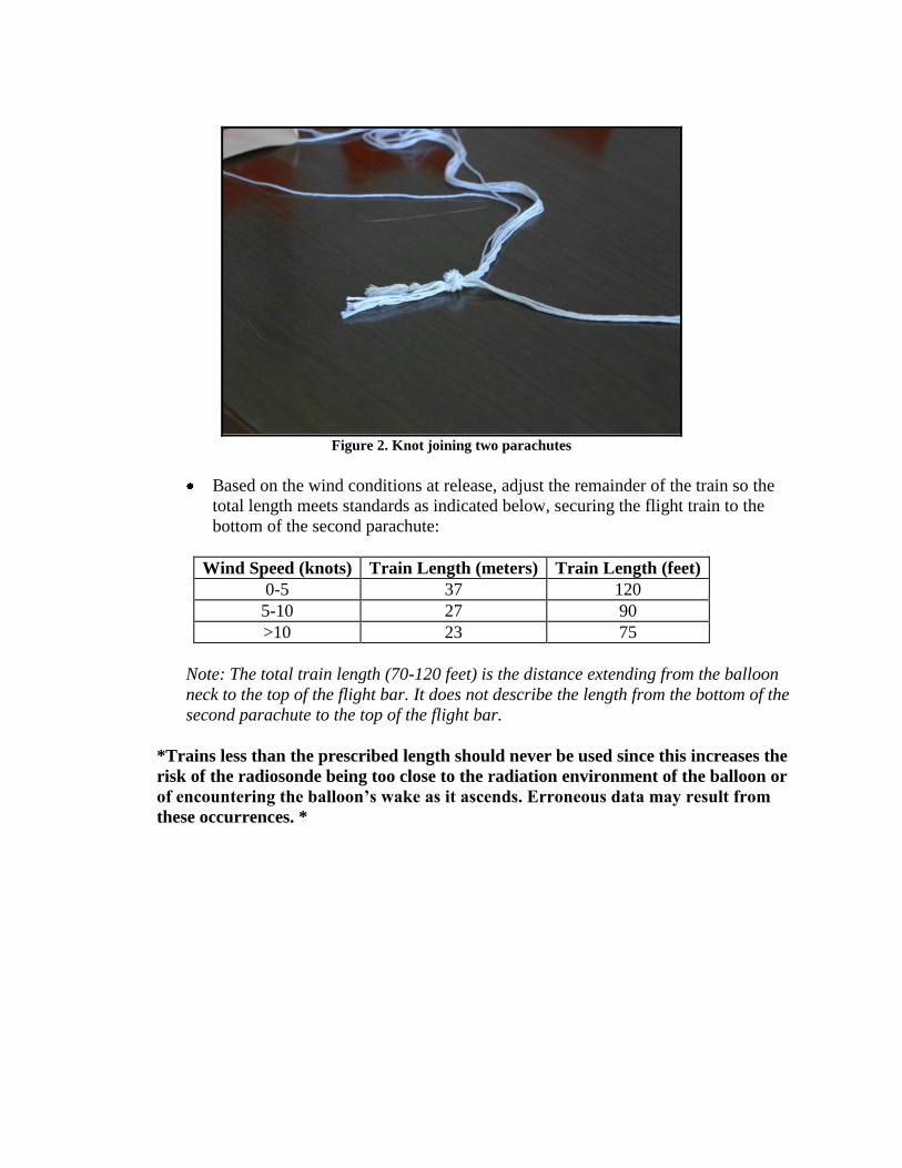
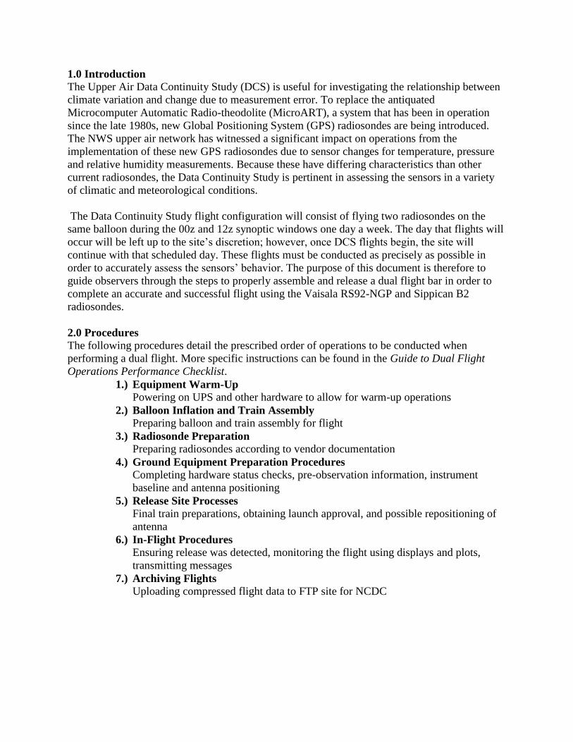
Figure 2. Knot joining two parachutes
Based on the wind conditions at release, adjust the remainder of the train so the
total length meets standards as indicated below, securing the flight train to the
bottom of the second parachute:
Wind Speed (knots) Train Length (meters) Train Length (feet)
0-5 37 120
5-10 27 90
>10 23 75
Note: The total train length (70-120 feet) is the distance extending from the balloon
neck to the top of the flight bar. It does not describe the length from the bottom of the
second parachute to the top of the flight bar.
*Trains less than the prescribed length should never be used since this increases the
risk of the radiosonde being too close to the radiation environment of the balloon or
of encountering the balloon’s wake as it ascends. Erroneous data may result from
these occurrences. *
Position and secure the flight bar on the RTS and tie the train assembly to the end
of the string extending from the top of the bar.
Figure 3. Tying flight train to flight bar
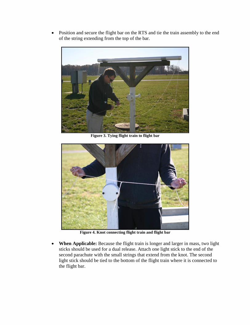
Figure 4. Knot connecting flight train and flight bar
When Applicable: Because the flight train is longer and larger in mass, two light
sticks should be used for a dual release. Attach one light stick to the end of the
second parachute with the small strings that extend from the knot. The second
light stick should be tied to the bottom of the flight train where it is connected to
the flight bar.
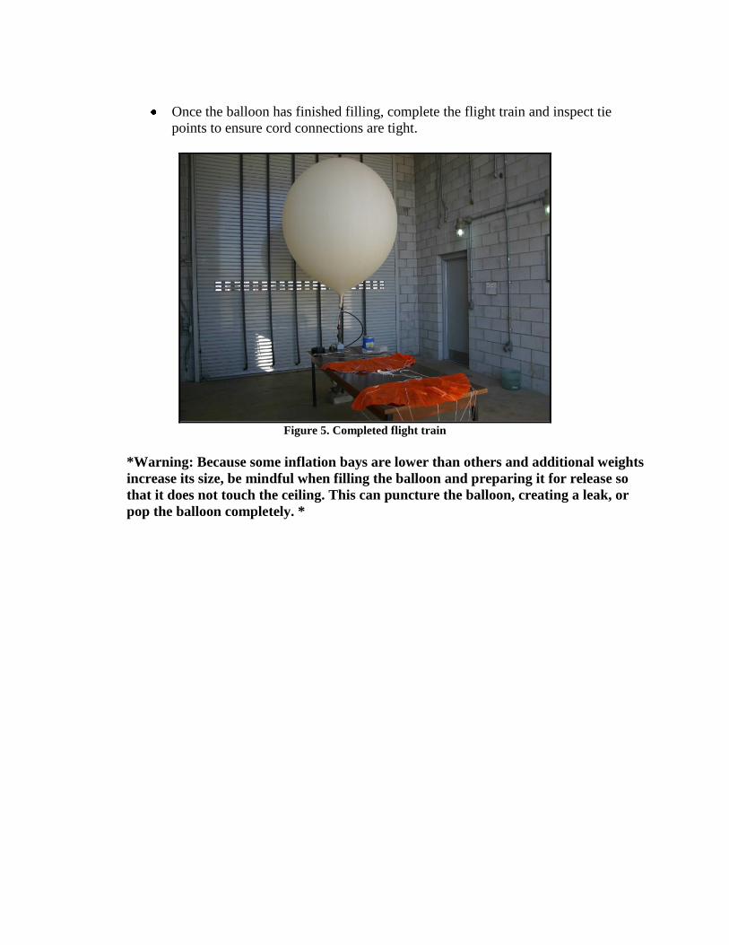
Once the balloon has finished filling, complete the flight train and inspect tie
points to ensure cord connections are tight.
Figure 5. Completed flight train
*Warning: Because some inflation bays are lower than others and additional weights
increase its size, be mindful when filling the balloon and preparing it for release so
that it does not touch the ceiling. This can puncture the balloon, creating a leak, or
pop the balloon completely. *
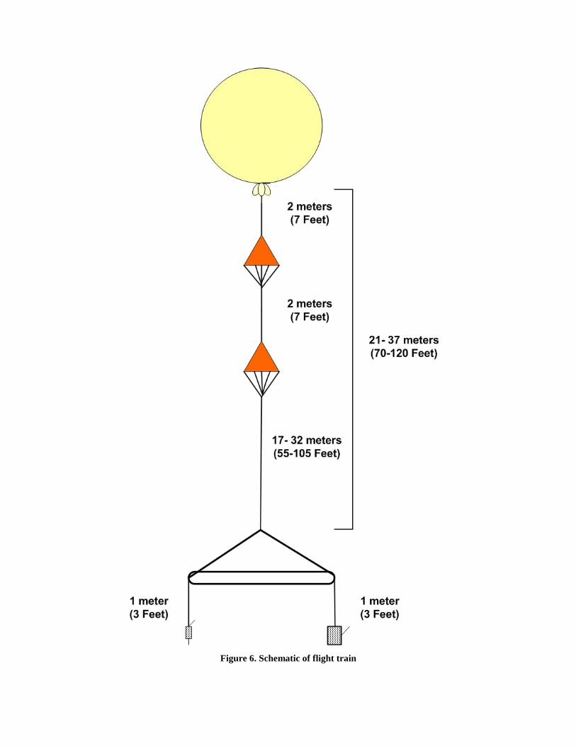
Figure 6. Schematic of flight train

3.1 Release Site Processes
Upon arriving at the release site, tie the radiosondes to the assembled flight bar,
first attaching the Vaisala RS92-NGP radiosonde to the string that has a knotted
loop. The loop should be slipped through the gaps in the eyelet. Following this,
the B2 radiosonde should be tied on to ensure that it hangs at the same height as
the RS92-NGP. This enables the radiosondes to collect data at the same points
and time, yielding a more reliable data comparison.
Figure 7. RS92-NGP on knotted loop on flight bar
Figure 8. Sippican B2 tied to assembled flight bar
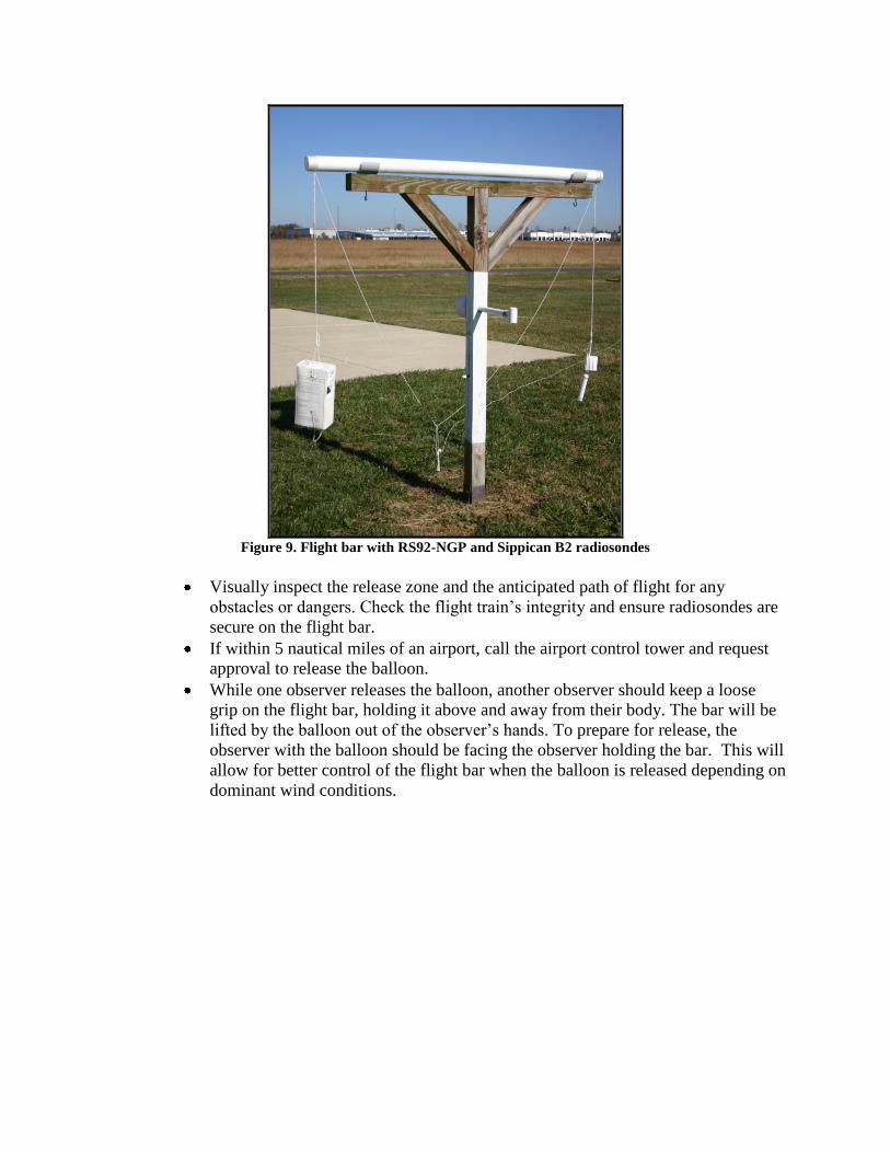
Figure 9. Flight bar with RS92-NGP and Sippican B2 radiosondes
Visually inspect the release zone and the anticipated path of flight for any
obstacles or dangers. Check the flight train’s integrity and ensure radiosondes are
secure on the flight bar.
If within 5 nautical miles of an airport, call the airport control tower and request
approval to release the balloon.
While one observer releases the balloon, another observer should keep a loose
grip on the flight bar, holding it above and away from their body. The bar will be
lifted by the balloon out of the observer’s hands. To prepare for release, the
observer with the balloon should be facing the observer holding the bar. This will
allow for better control of the flight bar when the balloon is released depending on
dominant wind conditions.

Figure 10. Preparing for balloon release with flight bar
Figure 11. Release of flight bar
After release, the observer can use the RCDU to verify the frequency has not
shifted for the Vaisala RS92-NGP. Double check to ensure the antenna is
positioned to the appropriate azimuth and elevation and that AFC is on. For the
Sippican B2, open the remote release panel and turn up the speaker volume to
check for a clean signal.
NWS Direct Field Support
The NWS Direct Field Support Help Desk serves to provide operational assistance to
National Weather Service field personnel with questions that pertain with the operation of a
new RWS system, including pre-flight and flight assistance during synoptic soundings. The
Radiosonde Replacement System (RRS) Help Line assists users in order to ensure continuity
in understanding of the RWS system and quality data collection among all operating
deployment sites.
Hours of Operation Contact
M-F 10:00-02:00 UTC (301) 713-9800 (703) 661-1293


