Guide for Design & Operation of Small-Scale Solar-Powered ... For Design %26 Operation … ·...
25
Guide for Design & Operation of Small-Scale Solar-Powered Network Resource Nodes Greenstar Network: Green IT: 216
Transcript of Guide for Design & Operation of Small-Scale Solar-Powered ... For Design %26 Operation … ·...

Guide for Design & Operation ofSmall-Scale Solar-PoweredNetwork Resource Nodes
Greenstar Network:Green IT: 216

Table of Contents
Acknowlegements ....................................................... 1
Abstract ....................................................................... 1
1.0 Introduction .....................................................2 1.1 Organization of this document .............................2
2.0 GSN Node Network Requirements .....................3 2.1 Solar vs Grid Power ............................................... 5 2.1 Maintaining Operating Environment ................... 5
3.0 GSN Node Network Requirements .....................6
4.0 Network Description ..........................................6 4.1 IP Address Allocation Scheme ............................ 6
5.0 GSN Node Server ...............................................8
6.0 GSN Node PDU ...................................................9
7.0 Remote Control and Monitoring of the Solar Powered System (SPS) or Wind Powered System (WPS) ....................................................9
8.0 Appendix “A” Description of the CRC Solar Powered Node .....9
9.0 Appendix “A.1” CRC Solar Powered Node Installation Photos .. 12
10.0 Appendix “A.2” Launching the greenMonitor Software ............. 14
11.0 Appendix “A.3” Configuration of the IOLAN DS1 Serial-to-IP Converter ................................................... 15
12.0 Appendix “B” Configuring the Allied Telesis AT-8000GS/24 Switch ................................................... 17
13.0 Appendix “C” Setting up the Arista Network 7124S L2/L3 Switch at ÉTS .................................................. 18
14.0 Appendix “D” Configuration of the GSN Servers.................... 19
Install KVM ................................................................19 Mounting the Storage Array Located at ÉTS.........19
15.0 Appendix “E” Configuring the Raritan PDU ........................... 20
16.0 Appendix “F” Configuration of the IOLAN DS1 Serial-to-IP Converter ...................................................22

1
Abstract
This document introduces Communication Research Centre
Canada’s (CRC) “GSN Node” to readers interested in
implementation and experience with very low carbon network
resources. This GSN Node was constructed by CANARIE’s
GreenStar Network Project; it provides small scale hosting of
virtual machines, intended as one of many such renewably-
powered nodes in a network of ICT resources. The GSN Node
was deployed in 2010 at CRC in Ottawa and at Cybera in
Calgary, and was used throughout 2010 - 2011.
This report provides practical guidance for designers of very
low carbon ICT facilities.
Key words: Renewable energy, network node, cloud computing
Acknowledgements
Appreciation is extended to the following for the creation of
this document:
• Michel Savoie & Bobby Ho,
Communications Research Centre Canada
• Martin Brooks & John Spence,
iDeal Consulting

2
1.0 Introduction
The CANARIE GreenStar Network Project designed, built
& fielded two identical outdoor, solar powered ICT facilities,
at Communications Research Centre Canada in Ottawa,
and Cybera in Calgary. Each node contained power &
environmental equipment, a Dell server running a virtual
machine hypervisor, and a network switch, all powered
by a bank of solar panels to the largest possible degree.
Control systems maintain each node’s power availability and
acceptable operating conditions. Software interfaces provide
remote computer monitoring & control.
CANARIE is Canada’s Advanced Research and Innovation
Network. CANARIE provided funding and technical support
for the GreenStar Network Project throughout 2010 – 2011 as
part of the $2.4 million Green IT Program. The program funded
for ground-breaking Green IT projects aimed at reducing
ICT’s carbon footprint and measuring the impact of ICT and
cyberinfrastructure on university electric consumption. The
GreenStar Network Project was led by Dr. Mohamed Cheriet,
at École de technologie supérieure in Montréal.
Communications Research Centre Canada (CRC) led design
and the first implementation of the solar-powered GSN Node. A
second, identical solar-powered GSN Node was subsequently
constructed at Cybera, in Calgary. The two nodes were in
continuous use throughout the GSN Project, as key elements
of a “follow-the-sun” very low carbon distributed cloud. Similar
nodes, but with varying power sources, were constructed in
China, Europe, USA and elsewhere in Canada.
By providing the GSN team’s insight & experience, the
GreenStar Network Project hopes to accelerate design &
deployment of very low carbon ICT facilities.
1.1 Organization of this document
This document provides a high-level description of the
concept & context of the GSN Node, with emphasis on the
multiple systems comprising the Node. Use of the GSN Node
within the very low carbon GSN Network is described, and
use experience and lessons learned are discussed. Finally,
technical aspects of the Node are presented in detail.
GSN Node Description
A GSN node should consist of the following Special Purpose
Equipment (SPE),
• A Layer 2 (L2) Switch• A Server based on the Intel E5500 or Later Chip Set• A Power Distribution Unit (PDU)• A Solar Powered System (SPS) or Wind Powered System
(WPS).
The SPS should include solar panels, a charge controller, an
inverter and battery banks. For the WPS, the solar panels
would be replaced by a wind turbine. Note that remote control
and monitoring is required for either an SPS or WPS.
A typical GSN node installation is depicted in Figure 1. The
CRC Solar Powered Node is fully described in Appendix “A”.

3
Figure 1. The CRC Solar Powered Node
MUX/DEMUXMUX/DEMUX
Allied Telesis AT-8000GS/24
ActivFlexBADLAB
ActivFlexOttawa
Raritan DPXR-8-15
Outdoor Enclosure withClimate Control (DBB Unlimited)
Charge Controller +Sealed Batteries
Grid Power
Sealed Inverter(Outback Inverter
FX2524T)
MATE
IOLAN DS1
SFP
C6509
9* Salon Blue (220W)Roof of Building 2CSolar Panels
C3750
Dell PowerEdge R710
Roof of Building 2A
2.0 GSN Nodes: design decisions and lessons learned
The GSN node was designed with the intent that it would be
one of several – or perhaps a large number – of identical
nodes across the world. Together, these nodes would provide
a renewably-powered distributed cloud. Virtual Machines
(VMs) would migrate from node to node, moving from nodes
having less renewable power to nodes having more.
The network and VM hosting components of the GSN Node
were replicated in several locations, including:
• Canada: Montréal (ÉTS) & Kelowna (RackForce)• Ireland: Dublin (DKIT) & Wexford (EPA)• Iceland: Reyjkavik (NORDUnet)• USA: San Diego (UCSD)• China: Shanghai (WiCO)
Outdoor solar powered GSN nodes were implemented only in
Ottawa (CRC) and Calgary (Cybera). This document focuses
on those two nodes, which were almost identical.
The nodes were the principal hardware component of the
GreenStar Network (GSN). In addition to the nodes, GSN
consisted of Research & Education network connections
between the nodes, middleware providing access & control
of the nodes, and “follow the sun & wind” controller software
that determined when, from where and to where VMs should
be migrated.
The CRC & Cybera nodes were unique among the GSN nodes
in two ways: (1) They were placed outdoors (on rooftops), and
therefore did not use indoor sources of temperature control;
and, (2) each was built alongside a dedicated bank of solar
panels that served as the primary source of power for the
compute & network node components.
This document focuses primarily on the CRC and Cybera solar
powered nodes.

4
Windmill located at DKIT Dundalk Institute of Technology, Dublin, Ireland.
Andrew Mackarel, HEAnet: Solar PV array at the EPA Environmental Protection Authority headquarters in Wexford, Ireland.

5
2.1 Solar vs Grid Power
Solar power was not intended as the only power source for
the nodes, due to several considerations, discussed in these
sections.
It was neither expected nor desirable that the solar panels,
together with their battery storage, should be able to provide
around-the-clock power. To the contrary, GSN is predicated
on the assumption that availability of renewable power will
wax & wane in relation to sun and wind. Part of GSN’s value
proposition was demonstration that continuous operation of
VMs could be achieved despite fluctuating power availability,
by means of controlled VM migration between nodes.
In full sun, with batteries fully charged, the GSN node’s
solar energy supply would be sufficient to power the outdoor
enclosure’s temperature and humidity controls as well as the
ICT gear inside it. However, environmental controls use the
majority of the power, and there were many daytime periods
when sunshine cannot maintain the batteries at full charge.
Therefore, it was decided that temperature and humidity
control would be powered by the grid; only the node’s server
(hosting VMs), network switch and power distribution unit
(PDU) were solar powered.
A central question arising early in the node design process was
what one should do with the server and switch during periods
of insufficient solar power: Turn them off, or power them
from the grid? The decision was to provide grid power when
solar power was not available, and thus maintain continuous
operation. This then led to the question of whether or not the
server should host VMs when operating under grid power.
The decision was “not, if possible”. In other words, as solar
power dwindles, the controller attempts to migrate the node’s
VMs to other nodes, but if for any reason this migration fails
or occurs too late – so that VMs are still running on the server
as it switches to grid power – then these VMs will continue
to run normally until they can be migrated. This discussion
shows that the node’s carbon footprint is non-zero, but as
small as practically achievable within the project’s constraints.
Another central question was to determine when to switch
between solar and grid power; the following design was
implemented: The battery bank consists of four deep cycle
12 V batteries in a 2+2 series-parallel configuration having a
nominal 24 V at the battery bank connection point. Although
nominally 24 V, in fact these batteries are typically charged up
to approximately 29 V. When discharging, the 50%-remaining
point, as identified by the battery manufacturer, is 24 V. Thus,
when the voltage drops below 24 V for one hour, then the
enclosure’s ICT gear is switched to grid power. When the
voltage remains at 26 V or above for one hour, then the ICT
gear is switched back to the solar-charged battery power.
2.2 Maintaining Operating Environment
The node’s outdoor enclosure was equipped with an air
conditioner for summer and a heater for winter. This aspect
was a significant source of operational challenges.
Both Ottawa and Calgary have cold winters and hot summers;
it turned out that heating during winter was the more difficult
problem. Based on observation of the enclosure’s interior
temperature falling below the recommended operating
temperature for the server and switch, a 400 watt heater
(with fan) was installed. With the additional heater we were
able to maintain the minimum operating temperature for the
server & switch.
During summer, measurements indicated the relative humidity
inside the container sometimes approached dangerous levels.
A “smoke test” determined that the enclosure’s door seals
were not fully functional; they were replaced, but high humidity
persisted. Although the enclosure’s air conditioner actively
vents moisture while active, the periods of air conditioner
activation were insufficient to vent enough moisture. This
problem was solved in innovative way: When the humidity
approached dangerous levels, the 400 W heater was turned
on, despite the fact that the summer requirement is to keep
the enclosure cool. Turning on the heater had two effects: It
insured that moisture did not condense, and it caused the air
conditioner to switch on and thereby vent the moisture out
of the enclosure.

6
3.0 GSN Node Network Requirements
A GSN node is expected to connect to the GreenStar Network
using a 1 Gbps LightPath (LP) across CANARIE that would
be terminated at the ÉTS Hub Node in Montréal using a 1
GbE interface.
For a site connecting through GÉANT, the preferred exchange
point with CANARIE is the MANLAN in New York.
The Special Purpose Equipment (SPE) that constitutes a GSN
Node includes an L2 Switch to connect the equipment to it
and to terminate the LP onto it. Due to the budget constraints
within the GSN project, the recommended L2 Switch is the
Allied Telesis AT-8000GS/24 model.
The required optics for the Small Form-factor Pluggable (SFP)
transceiver will depend on the distance and type of fibre used
to establish the connection between the L2 Switch and the
network end point. If CWDM equipment is used the matching
wavelength will be required.
For ÉTS, a second and more powerful L2 switch, an Arista
Network 7124S L2/L3 Switch, is required to terminate all the
LPs associated with the remote GSN nodes. Instructions on
how to configure the Allied Telesis AT-8000GS/24 and Arista
Network 7124S switches are contained in Appendices “B” and
“C” respectively. As the complexity of the network grows as the
number of GSN nodes that come on line, tagged and untagged
circuits will be used on the GreenStar Network. A third Cisco
3750 L2 Switch is introduced at Montreal to handle all the
tagged LP circuits. All untagged LP circuits are terminated
on the Arista L2/L3 Switch.
4.0 Network Description
For the first two phases of the GSN project, a flat network
is required to support the live migration of VMs. In the third
phase, virtual routing will be required to support multi-domains.
The following describes the flat network implementation.
4.1 IP Address Allocation Scheme
The following IP address scheme was deployed early in the
project. We have confirmed with most sites that this IP range
will not conflict with their local network. It was important to
ensure the IP address allocation scheme deployed did not
conflict with each node’s local IP network. Because of the
additional hardware requirements (data storage, multiple
servers, PDUs, L2 switches) to manage the hub at ÉTS, more
IP addresses were assigned to them.
Example of assignment:
10.20.100.0/2410.20.100.1 – 10.20.100.20 ÉTS10.20.100.21 – 10.20.100.30 CRC10.20.100.31 – 10.20.100.40 RackForce10.20.100.41 – 10.20.100.50 Cybera10.20.100.51 – 10.20.100.60 HEAnet 10.20.100.61 – 10.20.100.70 HEAnet 210.20.100.71 – 10.20.100.80 HEAnet 310.20.100.81 – 10.20.100.90 ……10.20.100.91 – 10.20.100.100 10.20.100.101 – 10.20.100.11010.20.100.111 – 10.20.100.120
10.20.100.121 and up will be used for the VMs using a DHCP
server. The DHCP server is located at ÉTS. The GSN IP
addressing scheme is depicted in Figure 2.

7
The successful national and international profile of the project
resulted in the need to accommodate additional GSN nodes
and revise the IP networking scheme.
Sample of revised IP addresses scheme.
10.20.0.0/17
10.20.101.0 and up are reserved for the DHCP server for VMs
10.20.100.0 - 10.20.100.255 to ÉTS10.20.99.0 - 10.20.99.255 to CRC10.20.98.0 - 10.20.98.255 to Cybera10.20.97.0 - 10.20.97.255 to GRC10.20.96.0 - 10.20.96.255 to RackForce10.20.95.0 - 10.20.95.255 to HEAnet #110.20.94.0 - 10.20.94.255 to HEAnet #2 (EPA)10.20.93.0 - 10.20.93.255 to HEAnet #3 (DKIT)10.20.92.0 - 10.20.92.255 to IBBT
10.20.91.0 - 10.20.91.255 to i2CAT10.20.90.0 - 10.20.90.255 to Calit210.20.89.0 - 10.20.89.255 to NORDUnet10.20.88.0 - 10.20.88.255 to WiCO10.20.87.0 – 10.20.87.255 to ….
All sites using 255.255.128.0 as the subnet mask. Default
gateway is available for L3 Internet access for software and
security update. Default gateway IP address is 10.20.100.251.
A development testbed was created to test new functionalities
to avoid disruption of the production network. VLAN 101 with
an IP range of 10.21.100.0/24 was trunked on the same LP.
The diagram below depicts the GSN network with all the STS
circuits and port assignments.
Figure 2. GSN IP Addressing Scheme
International Nodes
NORDUnetHEAnetCalit2WiCO
Allied TelesisAT-8000GS/24
Allied TelesisAT-8000GS/24
Cisco Nexus
Cisco UCS
HP Procurve
HP Servers
Allied TelesisAT-8000GS/24
Arista Network7124S
Dell PowerEdge R710 ServerHP Proliant DL 180G Disk Array
Dell PowerEdge R710 Server
Dell PowerEdge R710 Server
10.20.xxx.x
10.20.xxx.x
10.20.xxx.x
10.20.xxx.x
10.20.xxx.x
10.20.xxx.x
10.20.xxx.x
RackForce (Kelowna)
CRC (Ottawa)
ÉTS (Montreal)
Cybera (Calgary)GRC (Calgary)

8
Figure 3. CANARIE Network Resources Allocated to the GSN
Cisco 2950
Cisco 2950
Cisco 2950
L2 Switch
GÉANTRedIRIS
C-WAVEt
NORDUnet
SHAW10 Gbps
BCNET
MUX/DEMUX
MUX/DEMUX MUX/DEMUX
MUX/DEMUX
GRC
ActivFlex 6500Vancouver
ActivFlex 6500Calgary
Nexus 7000
Nexus 5010
Nexus 2148
CiscoUCS
ActivFlex 6500Chicago
ActivFlex 6500Toronto
ActivFlex 6500Ottawa
ActivFlex 6500Montreal
ActivFlex 6500New York
ActivFlex6500
Chicago
Cisco6509
DKIT
EPA
LP to HEAnetTagged Circuit
VLAN 153, 160, 960
TaggedVLAN 685
CoreDirector
ActivFlex 6500St. John’s
HP Procurve
Allied TelesisAT-8000GS/24
ActiveFlex BADLAB
Allied TelesisAT-8000GS/24
Allied TelesisAT-8000GS/24
Cisco Catalyst
JuniperMX480
Cisco6509
Catalyst3750
Catalyst 6509
TaggedCircuit
STS-21 STS-21STS-21
13-1
13-1
153
160
960
12-1
13-1 3.1
3-1
5-2 11-1
4-3 4-34-4
2 x GETrunked Circuit
GeoChronos and GSN Vlans
5 x GE
GEGE
8-1
5-5
8-3
6-3
6-1 12-1
17-1
18-1 17-1
10-1
17-117-1
16-1
18-1
TaggedCircuit
UntaggedCircuit
Tagged Circuit CarryingGSN Network &
GSN-Devel Network
Port 5-5 is a GEon the L255 Card
Arista Network7120-4S
Cybera CRC BADLAB
i2CAT, Spain
RackForce
MANLAN,New York
Calit2 HEAnet, Ireland
ÉTS Bastionhost
status: October 31, 2011
5.0 GSN Node Server
Minimum requirements: the server should support the Intel
E5500 or later chip set. The Dell PowerEdge R710 server*
was deployed with the following configuration,
Processor: Dual Xeon 2.4GHz Quad Core ProcessorsMemory: 48 GB 1333MHz Dual Ranked RDIMMsHard Disk Drive: 80 GB 7.2K RPM SATA 2.5” Hot Plug Hard
Drive
Instructions on how to configure the GSN servers are
contained in Appendix “D”.
*NOTE: selection and procurement of hardware was limited to budget
project allocation.

9
6.0 GSN Node PDU
The recommended PDU for a GSN node is the Raritan DPXR8-
15 PDU.
Power Distribution Unit (PDU) minimum requirements:
Network features: Telnet, SSH, SNMPPower Metrics: Each outlet on the PDU are individually
monitored
Instructions on how to configure the Raritan PDU are
contained in Appendix “E”.
7.0 Remote Control and Monitoring of the Solar Powered System (SPS) or Wind Powered System (WPS)
The Facility Manager component of the GSN Middleware
requires the ability to monitor parameters associated with
an SPS and/or a WPS. In addition, a network connection is
required to provide remote control and monitoring of SPS and
WPS. The SPS Outback equipment was selected for the CRC
GSN Node. The MATE system display and controllers are
the management tools for the Outback power system. The
MATE is accessible over the network using the IOLAN DS1
Serial-to-IP Converter.
Instructions on how to configure the IOLAN DS1 Serial-to-IP
Converter are contained in Appendix “F”.
8.0 Appendix “A” - Description of the CRC Solar Powered Node
Solar Powered Node at CRC
The installation of the Solar Powered System (SPS) at CRC
was completed and fully operational on March 2010. Photos
of the solar powered node installation at CRC are included
in Appendix “A.1”. The SPS is being used to power the node
consisting of the following equipment: one Raritan PDU with
temperature and humidity sensors, one R710 Dell server with
E5530 processors, one Allied Telesis AT-8000GS/24 and
one IOLAN DS1 Serial-to-IP converter. The AC output from
the inverter feeds the PDU and the remaining equipment is
connected to the PDU. The climate control (air conditioning

10
Figure A.1. Equipment Connectivity for CRC Solar Powered Node
ClimateControl
Watts up?.net
ChargeController Inverter
MATE
IOLANDS1
HUB
Sensor
Raritan PDU
Fibre Patch Panel
Fibre Patch Panel
Dell PowerEdge R710
Trunked LineL3 and L2 VLAN
Single Mode Fibre
Allied Telesis AT-8000GS/24Management 142.92.xx.xxx
PowerCable
Serial
1st Mate
100 Mbps
Management 142.92.xx.xxx
Management 142.92.xx.xxx
status: October 31, 2011
1000 Mbps
eth1 : 142.92.xx.xxxPower supply 1
Power supply 2 eth0 : 10.20.xxxx
Management142.92.xx.xxx
PowerCable
PowerCable
PowerCable
PowerCable
Grid Power
LX GBIC
2/12
LX SFP
8
g16g15g24 g1
g14g13
7 6 1
12
Outdoor Enclosure
Cisco6509
and heating element) associated with the DDB outdoor
enclosure is powered by the regular power grid. An Internet
enabled plug-load meter is configured to measure the power
usage by the climate control unit. The meter is remotely
accessible over the network.
Details on how the equipment is interconnected in the outdoor
enclosure are shown in Figure A.1.
The inverter has been programmed to use the alternate power
source (grid power), when the battery bank has dropped to
50% of its charge capacity (i.e. at the 24 Vdc set point for
one hour). It will drop the alternate power source when the
battery bank has reached the 26 Vdc set point and maintained
it for at least one hour.
The greenMonitor software was installed on a Virtual Machine
(VM) in the CRC BADLAB. The software was launched to
remotely control and monitor the CRC and Cybera SPS. The
greenMonitor Server is now able to retrieve live data from
the CRC and Cybera SPS. The Server’s main window is
shown in Figure A.2.
Figure A.2. greenMonitor Server’s Main Window

11
Various client applications can be launched from within
the Server’s main window. The screen shots for the Mate,
QuickView, and Viewer client applications are depicted in
Figures A.3-A.5.
Figure A.3. greenMonitor: Mate Window
Figure A.4. greenMonitor: QuickView Window
Figure A.5. greenMonitor: Viewer Window
Some initial software issues were experienced that resulted
in the inverter being inadvertently turned off. To rectify the
situation, one must access the Outback Mate in the outdoor
enclosure to manually issue the command to turn the inverter
back on. Support engineers at greenHouse Computers
concluded that it was due to the Outback Mate not recognizing
some character sequences in the serial command sent by the
greenMonitor software. A software update was issued that
fixed the problem. The greenMonitor support engineer also
provided some php scripts to enable posting of raw statistics
files onto websites. That can be useful at some point in the
project.
Instructions on how to launch the greenMonitor software are
included in Appendix “A.2”. Instructions on how to configure
the IOLAN DS1 Serial-to-IP converter are included in Appendix
“A.3”. Instructions on how to configure the Raritan PDU are
included in Appendix “A.4”.


14
10.0 Appendix “A.2” - Launching the greenMonitor Software
Double-click on the gmServer.bat executable in the
greenMonitor software windows installation. In the gmServer
main window, use the following parameters to connect to the
CRC serial-to-IP converter:
Under “Type”, select “Host”. In the host name field, specify
142.92.xxx.x, that’s the IP address of the Serial-to-IP Converter
attached to the CRC Outback Mate. Use ‘10001’ for both ‘TCP
Port’ and ‘Server Port’ fields. It is important to uncheck the
“Server” checkbox, because we are connecting to a Serial-to-
IP Converter, not another gmServer instance. After following
all of the above steps, click on the ‘Connect’ button, and the
‘Health’ column should have a green ‘Okay’ field displayed
underneath.
Remember to uncheck the ‘Server’ checkbox again in case
it’s automatically checked after having connected. Now you
can see a list of available greenMonitor utilities by clicking on
‘142.92.xx.:10001’ under the ‘Host’ column.
To save your connection settings, select “System” from the
“Type” pulldown menu, then click “Save”. This will ensure that
the changes are reloaded the next time you start the gmServer.

15
11.0 Appendix “A.3” - Configuration of the IOLAN DS1 Serial-to-IP Converter
Configuring the Perle IOLAN DS1 Serial-to-IP converter will require the CD, which is included along with the unit. Connect the unit and the PC to the same VLAN or using a cross over cable. When you start the CD, you should see the following screen.
Select EasyConfig to configure the IOLAN DS1 with a static IP address (can also use DHCP if required).
Select IOLAN Easy Configuration Wizard. This will install an
application onto your local drive. The application will detect
the IOLAN DS1 unit.
Select “Next” to scan the network for available IOLAN DS1
devices.
All available devices will be listed under the IOLAN List. Select
the device you want to configure and select “Next”.

16
Assign a System Name and select “Use the following IP
address”. Manually enter the IP address, subnet mask and
the default gateway, and then click “Next”. This will download
the new configuration to the IOLAN DS1 device. When the
download is completed, connect the Ethernet cable to the
correct network port and the DS1 should now be accessible
via a web browser as shown below.

17
12.0 Appendix “B” - Configuring the Allied Telesis AT-8000GS/24 Switch
1) Configure AT-8000GS
For the CLI Commands of the Allied Telesis switch, please
refer to,
http://www.alliedtelesis.com/media/datasheets/guides/AT-
S95_V20019_CLI_Guide_RevA.pdf
a. Configure startup from terminal window Using the RS232 adaptor that comes with the Allied Telesis,
you can connect to the switching using a terminal emulator application like HyperTerminal from Microsoft Windows.
- Set the data format to 8 data bits, 1 stop bit, and no parity. - Set Flow Control to none. - Under Properties, select VT100 for Emulation mode. The default user name is “manager” and default password
is “friend”. Configure enable password, hostname, username, remote
access, snmp, etc. CLI is very similar to Cisco’s CLI. # configure (config)# hostname <hostname> (config)# username <username> password <password> (config)# snmp-server community public ro (config)# exit # clock hh:mm:ss may 3 2010
b. Configure interface for GreenStar Network # configure (config)# Vlan database (config-vlan)# vlan 100 (config-vlan)# exit (config)# exit #
# configure (config)# interface vlan 100 (config-if)# description GreenStar Network (config-if)# ip address 10.20.100.x 255.255.255.0 (config-if)# exit (config)# interface ethernet g25 (config-if)# switchport mode access (config-if)# switchport access vlan 100 (config-if)# no shutdown (config-if)# exit
(config)# exit # # copy running-config startup-config // This will save
the configuration
2) Establish an L3 connection to the Allied Telesis AT-8000GS for remote access.
Note: This does not require a GbE connection. This is only a control
plane for ARGIA access.
3) Establish a connection from the Allied Telesis AT-8000GS (GbE SFP) to the OME on CANARIE’s network.
4) Request has been made to CANARIE for the LP from each node to ÉTS (and between RF and GRC). Need to obtain the resource from CANARIE to have the circuits all in place.
a. CANARIE has indicated that the circuits will most likely be STS-3c-7v. May be able to request STS-24c.
5) Establish a ping between the AT-8000GS interfaces once the circuits on the CANARIE Network are in place.
6) Throughput testing: Would request a simple PC with iPerf running on the GSN APN for throughput testing to verify that we are achieving Gbps rates.
a. Will require SSH access or have iPerf daemon running.7) Install KVM on the Dell server as the host OS.8) Connect the Dell server (when ready) to the AT-8000GS
switch.

18
13.0 Appendix “C” - Setting up the Arista Network 7124S L2/L3 Switch at ÉTS
The Arista Network L2 switch will be used for routing the
tagged VLANs coming from the extended nodes coming from
HEAnet in Ireland, IBBT in Belgium, and i2CAT in Spain.
Current IP address for the 7124S at ÉTS is 217.162.xxx.xx.
# configure terminal(config)# hostname arista-gsn(config)# interface management 1(config-if-Ma1)# ip address 10.20.xxx.xx.255.255.255.0(config-if-Ma1)# interface management 2(config-if-Ma2)# ip address 217.162.xxx.xx 255.255.255.0(config-if-Ma2)# exit(config)# ip routing(config)# snmp-server community public RO(config)# vlan 100(config)# vlan 153 #HEAnet tagged VLAN ID(config)# vlan 160 #HEAnet tagged VLAN ID(config)# vlan 960 #HEAnet tagged VLAN ID(config)# interface ethernet 21(config-if-Et21)# description “1490nm - BastionHost”(config-if-Et21)# switchport access vlan 100(config-if-Et21)# interface ethernet 22(config-if-Et22)# description “1530nm - Cybera”(config-if-Et22)# switchport access vlan 100(config-if-Et22)# interface Ethernet23(config-if-Et23)# description “1550nm - CRC”(config-if-Et23)# switchport access vlan 100(config-if-Et23)# interface Ethernet24(config-if-Et24)# description “1570nm - HEAnet”(config-if-Et24)# switchport mode trunk(config-if-Et24)# switchport truck allow vlan all

19
14.0 Appendix “D” - Configuration of the GSN Servers
Before booting up and installing KVM, the Intel’s VT-x feature
must be enabled in the BIOS for virtualization support. As
well, the server BIOS must be configured to automatically
boot when power is detected. This can be found under the
power management option within the BIOS.
Install KVM
1. Install the Operating System. Ubuntu 10.04 LTS 64-bit OS2. Activate the virtualization capability of PCs. This function
is found in the “Performance” category of the setup menu of PCs (press F2 or F12 when booting a PC).
3. Install kvm: sudo apt-get install kvm4. Install libvrt: sudo apt-get install libvirt-bin5. Once installed, you can verify that everything okay by
running: kvm-ok If you get the following message you are good to go,
otherwise something not configured or the BIOS is not set for HW Virtualization:
# kvm-ok INFO: Your CPU supports KVM extensions INFO: /dev/kvm exists KVM acceleration can be used
Mounting the Storage Array Located at ÉTS
1. Mount a shared storage to all the hosts. I use sshfs: sshfs -o idmap=user $USER@storageIP:/home/vmm /home/vmm
• To interconnect the testbed with the main GSN testbed, you will need to use the same shared storage at ETS.
2. If you want to move a VM from host1 to host2, make sure that both hosts appear in the /etc/hosts of each other, because by default libvirt does not recognise IP addresses.
3. You may want to install virt-manager in order to have a graphical interface. The current version of virt-manager has some bugs when moving VMs. So it would be better to install virt-manager 0.8.4: http://pyl.pylanglois.com/2010/05/12/how-i-installed-virt-manager-0-8-4-on-ubuntu-10-04/
4. Create a generic username “GsnM-ws-VmmEngine”.
Create a RSA Key and export this key to the other servers, so that when migrating from node to node, the user will not require to input the password every time. Only need to input the password once during the RSA Key upload.
5. Use vmbuilder to create vm: • sudo apt-get install ubuntu-vm-builder • cd /home/vmm • sudo ubuntu-vm-builder kvm karmic --addpkg
openssh-server --addpkg screen --mem 256 --libvirt qemu:///system
6. Start VM and move it using virt-manager or virsh command line:
• sudo virsh; • virsh#start ubuntu • virsh#list (This will list the VMs that are currently
running on the server) • virsh#migrate ubuntu qemu+ssh://remotehost/system

21
Alternative option:
In the case of Cybera, the network configuration of the Raritan
PDU was done remotely. If the Raritan unit is installed in the
outdoor enclosure and you would like to configure or make
network configuration changes to the Raritan, you can do so
by connecting the serial adapter to the serial port on the Dell
R710 server co-located inside the enclosure. Using SSH, log
onto the server that should already have Ubuntu 10.04 64-bit
Server OS running. Using a terminal emulator like minicom,
changes to the network preferences can be made.
#apt-get update#apt-get install minicom#minicom –s
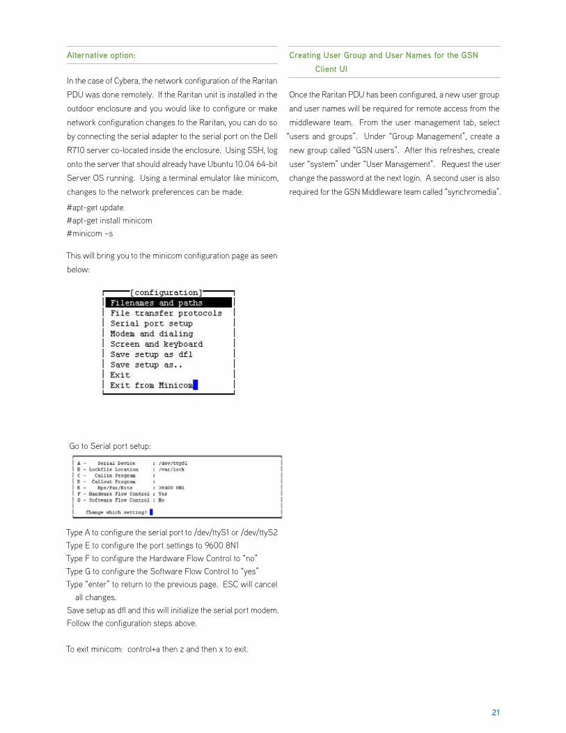
This will bring you to the minicom configuration page as seen
below:
Go to Serial port setup:
Type A to configure the serial port to /dev/ttyS1 or /dev/ttyS2 Type E to configure the port settings to 9600 8N1Type F to configure the Hardware Flow Control to “no”Type G to configure the Software Flow Control to “yes”Type “enter” to return to the previous page. ESC will cancel
all changes.Save setup as dfl and this will initialize the serial port modem.Follow the configuration steps above.
To exit minicom: control+a then z and then x to exit.
Creating User Group and User Names for the GSN
Client UI
Once the Raritan PDU has been configured, a new user group
and user names will be required for remote access from the
middleware team. From the user management tab, select
“users and groups”. Under “Group Management”, create a
new group called “GSN users”. After this refreshes, create
user “system” under “User Management”. Request the user
change the password at the next login. A second user is also
required for the GSN Middleware team called “synchromedia”.

22
16.0 Appendix “F” - Configuring the IOLAN Serial to IP Converter
Configuring the Perle IOLAN DS1 will require the CD which is
included along with the unit. Connect the unit and the PC to
the same VLAN or using a cross over cable. When you start
the CD, you should see the following screen.
Select EasyConfig to configure the IOLAN with a static IP
address (can also use DHCP if required).
Select IOLAN Easy Configuration Wizard. This will install an
application onto your local drive. The application will detect
IOLAN DS1 unit.
Select “Next” to scan the network for available IOLAN DS1
devices.
All available devices will be listed under the IOLAN List.
Select the device you want to configure and select “Next”.

23
Assign a System Name and select “Use the following IP
address”. Manually enter the IP address, subnet mask
and the default gateway, and then click “Next”. This will
download the new configuration to the IOLAN DS1 device.
When the download is completed, connect the Ethernet
cable to the correct network port and the DS1 should now
be accessible via a web browser as shown below.


![Apostila Cursos CRC - Administração de Departamento Pessoal CRC[1]](https://static.fdocuments.net/doc/165x107/5571f85049795991698d254a/apostila-cursos-crc-administracao-de-departamento-pessoal-crc1.jpg)