Guidance on Taped Insulating Sheathing Drainage Planes ... · PDF file1 Guidance on Taped...
57
Guidance on Taped Insulating Sheathing Drainage Planes: Final Report Research Report - 1301 December 2012 Aaron Grin and Joseph Lstiburek Abstract: building science.com © 2013 Building Science Press All rights of reproduction in any form reserved. The order of work completed during home construction and retrofit improvements is important. Health and safety issues must be addressed first and are more important than durability issues. And durability issues are more important than saving energy. Not all techniques can apply to all houses. Special conditions will require special action. Some builders or homeowners will wish to do more than the important but basic retrofit strategies outlined by this guide.
Transcript of Guidance on Taped Insulating Sheathing Drainage Planes ... · PDF file1 Guidance on Taped...
1
Guidance on Taped InsulatingSheathing Drainage Planes:Final Report
Research Report - 1301 December 2012Aaron Grin and Joseph Lstiburek
Abstract:
building science.com © 2013 Building Science Press All rights of reproduction in any form reserved.
The order of work completed during home construction and retrofit improvements is important.Health and safety issues must be addressed first and are more important than durability issues.And durability issues are more important than saving energy. Not all techniques can apply to allhouses. Special conditions will require special action. Some builders or homeowners will wish todo more than the important but basic retrofit strategies outlined by this guide.

NOTICE
This report was prepared as an account of work sponsored by an agency of the United States government. Neither the United States government nor any agency thereof, nor any of their employees, subcontractors, or affiliated partners makes any warranty, express or implied, or assumes any legal liability or responsibility for the accuracy, completeness, or usefulness of any information, apparatus, product, or process disclosed, or represents that its use would not infringe privately owned rights. Reference herein to any specific commercial product, process, or service by trade name, trademark, manufacturer, or otherwise does not necessarily constitute or imply its endorsement, recommendation, or favoring by the United States government or any agency thereof. The views and opinions of authors expressed herein do not necessarily state or reflect those of the United States government or any agency thereof.
Available electronically at http://www.osti.gov/bridge
Available for a processing fee to U.S. Department of Energy and its contractors, in paper, from:
U.S. Department of Energy Office of Scientific and Technical Information
P.O. Box 62 Oak Ridge, TN 37831-0062
phone: 865.576.8401 fax: 865.576.5728
email: mailto:[email protected]
Available for sale to the public, in paper, from: U.S. Department of Commerce
National Technical Information Service 5285 Port Royal Road Springfield, VA 22161 phone: 800.553.6847
fax: 703.605.6900 email: [email protected]
online ordering: http://www.ntis.gov/ordering.htm
Printed on paper containing at least 50% wastepaper, including 20% postconsumer waste

Task 7 - Evaluation of Advanced Retrofit Measures and Development of Retrofit Measure Guidelines
Deliverable 7.2.2 – Guidance on Taped Insulating Sheathing Drainage
Planes: Final Report
Prepared for:
Building America
Building Technologies Program
Office of Energy Efficiency and Renewable Energy
U.S. Department of Energy
Prepared by:
Building Science Corporation
30 Forest Street
Somerville, MA 02143
December 2012

[This page left blank]

i
Contents List of Figures............................................................................................................................................. ii List of Tables ............................................................................................................................................. iii Definitions .................................................................................................................................................. iv Abstract .......................................................................................................................................................1 Progression Summary ...............................................................................................................................2 1 Introduction..............................................................................................................................................2 2 Decision Making Criteria.........................................................................................................................4
Cost and Performance ................................................................................................................4 Risk Identification......................................................................................................................4
3 Technical Description .............................................................................................................................5 4 Recommended Best Practices ...............................................................................................................5
Penetration Details .....................................................................................................................5 Insulating Sheathing Joint Requirements, Recommendations, and Tape Materials..................9
5 Construction Sequencing Details for Recommendations .................................................................13 GOOD - Basic Exterior Insulation Drainage Plane .................................................................13 BETTER - Improved Exterior Insulation Drainage Plane.......................................................16 BEST – Z-Flashed Exterior Insulation Drainage Plane...........................................................19
6 Summary ................................................................................................................................................22 Attachment A: Compliance......................................................................................................................24 Attachment B: Product Materials............................................................................................................29 References ................................................................................................................................................30 Appendix A – Homebuilder Interviews ...................................................................................................31 Appendix B: Future Research - Exposure Rack Recommendation Verification ................................32

ii
List of Figures Figure 1 - Pan Flashing to Drain Openings..............................................................................................6 Figure 2 - Types of Pan Flashing ..............................................................................................................7 Figure 3 - Step 1 - Install Insulating Sheathing........................................................................................7 Figure 4 - Step 2 - Install Backdam ...........................................................................................................7 Figure 5 - Step 3 Apply First Piece of Self-Adhered Sill Flashing .........................................................7 Figure 6 - Step 4 Install Second Piece of Sill Flashing ...........................................................................8 Figure 7 - Step 5 Install Corner Flashing Patches...................................................................................8 Figure 8 - Step 6 Install Window ...............................................................................................................8 Figure 9 - Step 7 Install Self Adhered Jamb Flashing.............................................................................8 Figure 10 - Step 8 Install Self Adhered Head Flashing ...........................................................................8 Figure 11 - Step 9 Termination Tape top edge of head flashing ............................................................8 Figure 12 - Roof to Wall Intersection ........................................................................................................9 Figure 13 – Example Through Drainage Plane Z-Flashing ...................................................................11 Figure 14 – Example Termination Tape Offset High on Butyl Tape.....................................................11 Figure 15 – Example Wide Tape Intentionally Offset High ...................................................................12 Figure 16 - West Test Panels...................................................................................................................33 Figure 17 - Center and East Test Panels ................................................................................................33 Figure 18 - West Test Panel Layout ........................................................................................................34 Figure 19 - Center and East Panel Layout..............................................................................................34 Figure 20 - Full Exposure Test Platform.................................................................................................35 Figure 21 - Typar Tape on ffPIC (left) and XPS (right)...........................................................................36 Figure 22 - Typar Tape with Termination Tape on ffPIC (right) and XPS (left) ...................................36 Figure 23 - Typar Tests ............................................................................................................................36 Figure 24 - Henry Blueskin on ffPIC (left) and XPS (right)....................................................................37 Figure 25 - Henry Blueskin with Termination Tape on ffPIC (right) and XPS (left) ............................37 Figure 26 – Henry Blueskin Tests ...........................................................................................................37 Figure 27 - Dupont Tyvek Tape on ffPIC (left) and XPS (right).............................................................38 Figure 28 - Tuck Tape on ffPIC (left) and XPS (right) ............................................................................38 Figure 29 - Dupont Tyvek Tape Tests.....................................................................................................38 Figure 30 - Tuck Tape Tests ....................................................................................................................38 Figure 31 - Dupont Straightflash Tape on ffPIC (left) and XPS (right).................................................39 Figure 32 - Dupont Straightflash Tape Tests .........................................................................................39 Figure 33 – Dow Weathermate Butyl with Termination Tape on ffPIC (left) and XPS (right).............40 Figure 34 - Dow Weathermate Butyl with Termination Tape Tests......................................................40 Figure 35 – Dow Weathermate Butyl on ffPIC (left) and XPS (right)....................................................41 Figure 36 - Dow Weathermate Butyl Tests.............................................................................................41 Figure 37 – Dow Weathermate Acrylic on ffPIC (left) and XPS (right).................................................42 Figure 38 – Dow Weathermate Acrylic Tests .........................................................................................42 Figure 39 - Dow Weathermate Acrylic on ffPIC - Large Test ................................................................43 Figure 40 - Dow Aluminum White Foil on ffPIC - Large Test................................................................43 Figure 41 - Dow Aluminum Foil on ffPIC - Large Test...........................................................................43 Figure 42 - Dow Weathermate Butyl on ffPIC - Large Test ...................................................................43 Figure 43 - Dow Weathermate Acrylic on XPS - Large Sample............................................................44 Figure 44 - Dupont Tyvek Tape on XPS - Large Sample.......................................................................44 Figure 45 - Dow Weathermate Butyl on XPS - Large Sample...............................................................44 Figure 46 - Dupont Straightflash on XPS - Large Sample ....................................................................44 Figure 47 – West Large Sample Tests Upper.........................................................................................45 Figure 48 – West Large Sample Tests Lower ........................................................................................45 Figure 49 - Center Small Sample Tests ..................................................................................................46 Figure 50 - East Small Sample Tests ......................................................................................................47

iii
List of Tables
No table of figures entries found.
iv
Definitions
ffPIC Foil Faced Polyisocyanurate XPS Extruded Polystyrene

1
Abstract
This guide provides information and recommendations to the following groups:
• Insulation contractors • General contractors • Builders • Home remodelers • Mechanical contractors • Homeowners as a guide to the work that needs to be done
The order of work completed during home construction and retrofit improvements is important. Health and safety issues must be addressed first and are more important than durability issues. And durability issues are more important than saving energy. Not all techniques can apply to all houses. Special conditions will require special action. Some builders or homeowners will wish to do more than the important but basic retrofit strategies outlined by this guide. The following research was conducted by the Building Science Corporation (BSC) Building America Research Team’s “Energy Efficient Housing Research Partnerships” project for Task Order No. KNDJ-1-40337-03. Guidance on Taped Insulating Sheathing Drainage Planes is Subtask 7.2 under Task 7.0 – Evaluation of Advanced Retrofit Measures and Development of Retrofit Measure Guidelines. The goal of this research is to provide durable and long-term water management solutions using exterior insulating sheathing as part of the water management system. It is possible to tape or seal the joints in insulating sheathing to create a drainage plane and even an air control layer. There exists the material durability component of the tape as well as the system durability component being the taped insulating sheathing as the drainage plane. The following are best practice and product recommendations from the interviewed contractors and homebuilders who collectively have a vast amount of experience. Three significant items were discussed with the group which are required to make taped insulating sheathing a simple, long term, and durable drainage plane:
1. Horizontal joints should be limited or eliminated wherever possible 2. Where a horizontal joint exists use superior materials 3. Frequent installation inspection and regular trade training are required to maintain proper
installation Section 5 of this measure guideline contains the detailed construction procedure for the three recommended methods to effectively seal the joints in exterior insulating sheathing to create a simple, long term, and durable drainage plane.
2
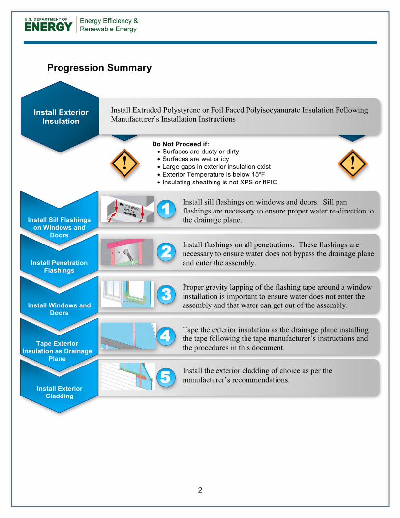
Progression Summary
ss
Do Not Proceed if: • Surfaces are dusty or dirty • Surfaces are wet or icy • Large gaps in exterior insulation exist • Exterior Temperature is below 15°F • Insulating sheathing is not XPS or ffPIC
! !
Install Sill Flashings
on Windows and Doors
Install sill flashings on windows and doors. Sill pan flashings are necessary to ensure proper water re-direction to the drainage plane.
1
Install Penetration
Flashings
Install flashings on all penetrations. These flashings are necessary to ensure water does not bypass the drainage plane and enter the assembly.
2
Install Windows and Doors
Proper gravity lapping of the flashing tape around a window installation is important to ensure water does not enter the assembly and that water can get out of the assembly.
3
Tape Exterior Insulation as Drainage
Plane
Tape the exterior insulation as the drainage plane installing the tape following the tape manufacturer’s instructions and the procedures in this document.
4
Install Exterior Cladding
Install the exterior cladding of choice as per the manufacturer’s recommendations. 5
Install Exterior Insulation
Install Extruded Polystyrene or Foil Faced Polyisocyanurate Insulation Following Manufacturer’s Installation Instructions
3
1 Introduction
The lowest-cost, highest performing rainwater management strategy is rigid polymeric foam sheathing with sealed joints (Lstiburek 2006, 2010). There is an existing construction challenge of sealing the joints in rigid polymeric foam sheathing in a reliable and durable manner to prevent water ingress. This research provides simple, long term, and durable solutions to the water intrusion issues that are possible by using tapes and membranes as integral portions of the drainage plane of the wall system. The knowledge gained from this research will be used in future Building America construction prototypes and well as other residential construction projects to increase the long-term moisture related durability of the enclosure, and reduce the risk of liquid water intrusion. Sustainability is not possible without durability; if you double the life of a building and you use the same amount of resources to construct it, the building is twice as resource efficient. Therefore durability is a key component of sustainability. It seems that one thing that both the development community and the environmental community can agree on is that durability is a good thing. The lessons of durability have come principally out of failure. Engineering is an iterative process of design by failure. Buildings are constructed. Problems are experienced. Designs and processes are changed. Better buildings are constructed. The building industry is in essence a reactive industry, not a proactive industry. It can be argued that the industry continues to do things until they become intolerably bad and then the industry changes. Examining failures gives us guidance on increasing the durability of building constructions. (BSD – 144) Taping and sealing of joints in insulating sheathing has been occurring for over two decades. Some failures and many successes have been reported over this time frame. A survey of existing installations, installers, contractors, and builders was conducted to determine the factors of success and failure. The recommendations are being refined using laboratory testing and field exposure testing. The exposure testing and feedback from contractors may be used to help or direct the development of new and refinement of current products. The survey provides insight into how builders across the country make taped insulating sheathing a simple, long term, and durable drainage plane. The team members involved with this project include members from Building Science Corporation, BASF, Dow, and Dupont.

4
2 Decision Making Criteria
Overall, the goal of the U.S. Department of Energy's (DOE) Building America program is to “reduce home energy use by 30%-50% (compared to 2009 energy codes for new homes and pre-retrofit energy use for existing homes).” To this end, we conduct research to “develop market-ready energy solutions that improve efficiency of new and existing homes in each U.S. climate zone, while increasing comfort, safety, and durability.” Using exterior board foam insulation as part of a whole house retrofit package can be a very effective method to reduce heat loss through the wall system aiding in achieving the energy use reduction goals of the U.S. DOE. Sealing the face of certain board foam insulation products can create an effective and code approved drainage plane. Some moisture related ingress failures due to failed joints have occurred in using this system prompting the necessity to develop further recommendations to improve the durability of the system. Cost and Performance It is difficult to assign a cost to durability but the costs and associated issues that occur with enclosure failures resulting in moisture durability issues are very expensive. Our experience with many production homebuilders in the United States has provided us with anecdotal evidence that the costs (on average) to repair a house, have increased an order of magnitude from approximately $100 ten years ago, to approximately $1500 today, largely as a result of water management issues. Because this is an average, and some houses have no reported problems, the houses that do have problems cost significantly more than $1500. This increase in costs is also related to an order of magnitude increase in the incidences of water management issues in the last decade from poorly installed and detailed water management systems. According to discussions during the survey of builders responsible for over 27,000 homes in 2011 the following cost related information is summarized. Most builders found when comparing taped insulating sheathing to installing a sheet weather barrier system, both methods had approximately the same total installed cost. The labour and material costs, when considering a whole house, were roughly the same. The decision to choose one method over the other generally is not made based on the cost of installation. One builder has found with continued use of taped insulating sheathing as the drainage plane that a cost savings has developed. As a secondary benefit, some builders have seen an improvement in whole house airtightness as a result of using taped insulating sheathing as the drainage plane. Risk Identification The builder survey indicated that taped insulating sheathing as the drainage plane has little to no risk when the correct materials are used and the installation is completed in a careful manner. Careless installation or improperly selected materials may result in issues. Each builder insisted that frequent installation inspection and regular trade training are required to maintain proper installation. The methods shown in Section 5 are the best practice recommendations that
5
minimize risk according to industry experience. Attachment A contains the ICC evaluation showing taped foam plastic insulating sheathing as a code compliant water-resistive barrier. 3 Technical Description
The following research questions will be answered by this project.
• What materials are available for this purpose? What are the characteristics of these materials?
• Which new materials meet the performance requirements for water management with insulating sheathing?
• What is the experience of installers in all climates? The performance of the taped sheathing system relies on material durability and system durability. The material durability component refers to the tape. The system durability component refers to the taped insulating sheathing as the drainage plane. Contractors have a unique perspective on these products and systems as they have first-hand experience in the site preparation & application. They also have an opportunity to see how the materials interact and perform over short time periods (e.g. during construction) and over longer time periods (e.g. through call-backs). Several contractors have implemented their own grass roots experimental programs to assess the buildability, performance, and durability of new products and systems. There is a need for researchers and product manufacturers to work with these contractors. An important first step is to document their experience, then to apply building science in the interpretation of the testing and to participate in the development of future products and testing. 4 Recommended Best Practices
Little argument should remain in the industry over the energy efficiency based financial benefits of adding exterior insulation. Using the exterior insulation as the drainage plane, removing the necessity to install a sheet or liquid applied weather barrier is the next logical step. Field implementation and durably taping the joints in the insulation in a repeatable manner is discussed in Section 5. To bring together the experience of the nation, six homebuilders were interviewed who represent the experience of building over 27,000 homes in 2011. Many of the recommendations from the homebuilders were in the form of recommended products or material properties (primarily adhesives). Installation methods and design recommendations are also included. Penetration Details In terms of window, door, and penetration flashing methods, most of the contractors and builders agreed that these details are already available and that using the right material and maintaining trade training and supervision were all that was required for success.
6
Flashings details are included in the following documents available online at www.buildingscience.com:
• Water Management Details – Housewraps/Flashings/Windows • Building Science Information Sheet 303 - Common Flashing Details • Building Science Digest-013 - Rain Control in Buildings • Building Science Digest-105 - Understanding Drainage Planes • Building Science Digest-144 - Increasing the Durability of Buildings
More details are available in these books by Building Science Press:
• Water Management Guide • Each of the climate specific Builder’s Guides
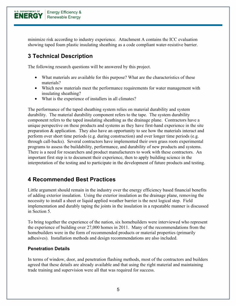
In addition, almost every tape or flashing product manufacturer have, or are building, their own in-house drawings which depict their recommended installation methods. Some of the most important penetrations to properly flash and drain are windows and doors. It is crucial to the durability of an assembly to install all windows and doors in a sub-sill pan flashing. All windows leak through their frames eventually and it is important that this water is properly directed outside the enclosure system. Figure 1 shows how the window or door is to sit in the pan flashing, Figure 2 shows three methods of creating the sub-sill pan flashing. The full process to install and flash the window is shown in Figure 3 through Figure 11. These same details shown can be applied to a door.
Figure 1 - Pan Flashing to Drain Openings

7
Figure 2 - Types of Pan Flashing
Figure 3 - Step 1 - Install
Insulating Sheathing
Figure 4 - Step 2 - Install
Backdam
Figure 5 - Step 3 Apply First Piece
of Self-Adhered Sill Flashing
8
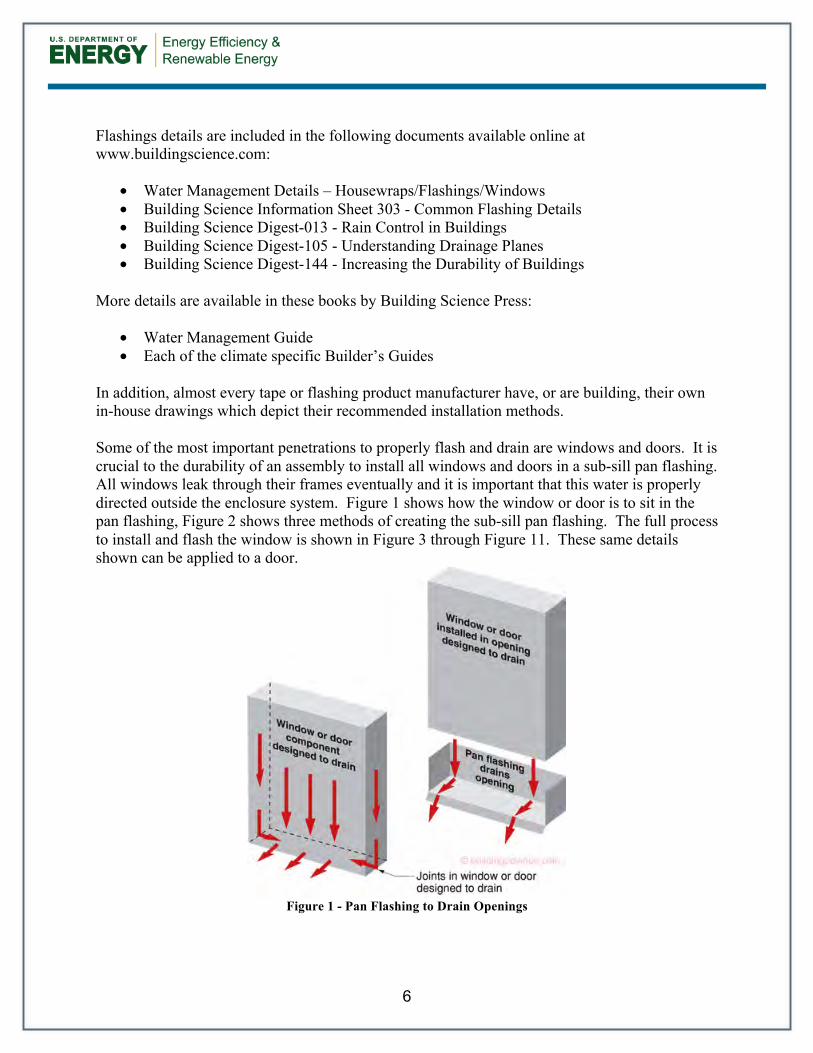
Figure 6 - Step 4 Install Second
Piece of Sill Flashing
Figure 7 - Step 5 Install Corner
Flashing Patches
Figure 8 - Step 6 Install Window
Figure 9 - Step 7 Install Self
Adhered Jamb Flashing
Figure 10 - Step 8 Install Self
Adhered Head Flashing
Figure 11 - Step 9 Termination Tape top edge of head flashing

9
Other key details covered in more detail in the recommended documents include penetrations as well as intersections between roofs and walls. An example roof to wall detail is shown in Figure 12.
Figure 12 - Roof to Wall Intersection
Insulating Sheathing Joint Requirements, Recommendations, and Tape Materials The following are best practice and product recommendations from the interviewed contractors and homebuilders who collectively have a vast amount of experience. Three significant items were discussed with the group which are required to make taped insulating sheathing a simple, long term, and durable drainage plane:
4. Horizontal joints should be limited or eliminated wherever possible 5. Where a horizontal joint exists use superior materials 6. Frequent installation inspection and regular trade training are required to maintain proper
installation Where horizontal joints cannot be avoided, it was recommended by all contractors that cheap/poor/inferior products and methods should be avoided. This includes using tapes that are not designed as sheathing tapes, using thin polyethylene as z-flashing, installing narrow tape, not following the manufacturer’s guidelines as to surface preparation etc. In their experiences, it is not worth the risk to save the few dollars to be found in buying the cheap tape materials or using short-cut methods and hoping they do not fail. Each group interviewed had specific opinions on what methods and products produced a successful taped insulating sheathing drainage plane. All of the groups have used taped insulating sheathing as the drainage plane although not all groups currently use this method. The following is a summary of the homebuilder’s opinions and recommendations:

10
• A superior thin tape is:
o Acrylic adhesive based o Available in wide widths up to 4” o Through experience be able to adhere to almost any substrate with high reliability
in a range of climatic situations o Have good temperature and UV resistance o Available nationwide at a competitive price
• A superior flashing tape is: o Butyl adhesive based o Not more than 20 mil thick (ensures overlaps do not build-up too much) o Available in 6” to 9” widths o Have a facer that is very expansion/contraction compatible with its adhesive
substrate o Have a facer that is no wider than the adhesive as to not trap water o Through experience be able to adhere to almost any substrate with high reliability
in a range of climatic situations o Have good temperature and UV resistance o Available nationwide at a competitive price, although builders would pay a
premium for a product that repeatedly performed reliably • Foil tapes rip easily, and their backer materials are sometimes difficult to deal with • Foil tapes can have the tendency to ‘walk-off’ their substrates over time • Drainage planes must be:
o Smooth or not significantly textured o Clean o Dust free o Ideally warm
• Tapes must be: o Clean o Dust free o Ideally warm
• Z-flashings should be used on any high-risk horizontal joint (Figure 13) o Contractors who have walls with high water deposition and/or wind loads prefer
to use Z-flashings for horizontal joints o Some contractors use this method for all horizontal joints o Butyl based tapes 6”-9” wide are preferred o No contractor recommends using polyethylene sheet as a Z-flashing

11
Figure 13 – Example Through Drainage Plane Z-Flashing
• Where thick tapes (20-30mil) are installed horizontally, a termination strip of thin tape
should always be used (Figure 14). • A tape termination strip is easier than a caulk termination strip.
Figure 14 – Example Termination Tape Offset High on Butyl Tape
• On horizontal joints, the tape should be offset favoring more tape and hence adherence to
the upper sheet of substrate. In general 2/3 of the tape should be on the top sheet, and the remainder lapped over the bottom sheet (Figure 15).

12
Figure 15 – Example Wide Tape Intentionally Offset High
• Backup wood blocking should be installed behind horizontal joint locations
o Provides a backup and stiffness o Allows the perimeter of the sheet to be fastened properly o Provides support for when the tape is installed
• In terms of flashing tapes, almost all groups interviewed prefer butyl base tapes over asphaltic based tapes
• Vertical joints should land on framing members and be taped with a minimum 3” wide acrylic tape and gravity lapped with the horizontal joint
In an effort to confirm the opinions of the homebuilders interviewed and provide some insight to the long-term lifespan of various tape materials, recommended for use in a taped insulating sheathing drainage plane, an outdoor exposure rack was developed and the tapes will be monitored over time. Details pertaining to the verification testing can be found in Appendix B. Section 5 of this measure guideline contains the detailed construction procedure developed from the contractor recommendations. Three recommended methods are provided to effectively seal the joints in exterior insulating sheathing to create a simple, long term, and durable drainage plane. Attachment B contains links to the materials discussed and recommended in this measure guideline.
13
5 Construction Sequencing Details for Recommendations
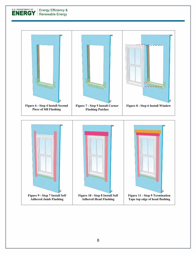
GOOD - Basic Exterior Insulation Drainage Plane
Steps 1 - 14
1. Frame wall
2. Install horizontal blocking where joints in the exterior insulation will exist
3. Install lower insulation as per
manufacturer’s recommendations
4. Clean taping areas
5. Tape vertical joint on lower insulation
6. Press tape firmly to ensure adhesion

14
7. Install upper insulation as per
manufacturer’s recommendations
8. Clean taping areas
9. Tape horizontal joint with minimum 3”
wide tape placing tape offset high on the joint. 2/3 of the tape should be adhered to the upper sheet of insulation.
10. Press tape firmly to ensure adhesion
11. Clean taping areas
12. Install tape on vertical joint of upper
insulation
13. Press tape firmly to ensure adhesion

15
14. Wall is now ready for exterior cladding
installation
16
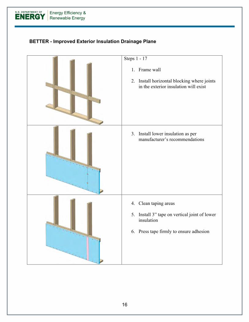
BETTER - Improved Exterior Insulation Drainage Plane
Steps 1 - 17
1. Frame wall
2. Install horizontal blocking where joints in the exterior insulation will exist
3. Install lower insulation as per
manufacturer’s recommendations
4. Clean taping areas
5. Install 3” tape on vertical joint of lower
insulation
6. Press tape firmly to ensure adhesion
17
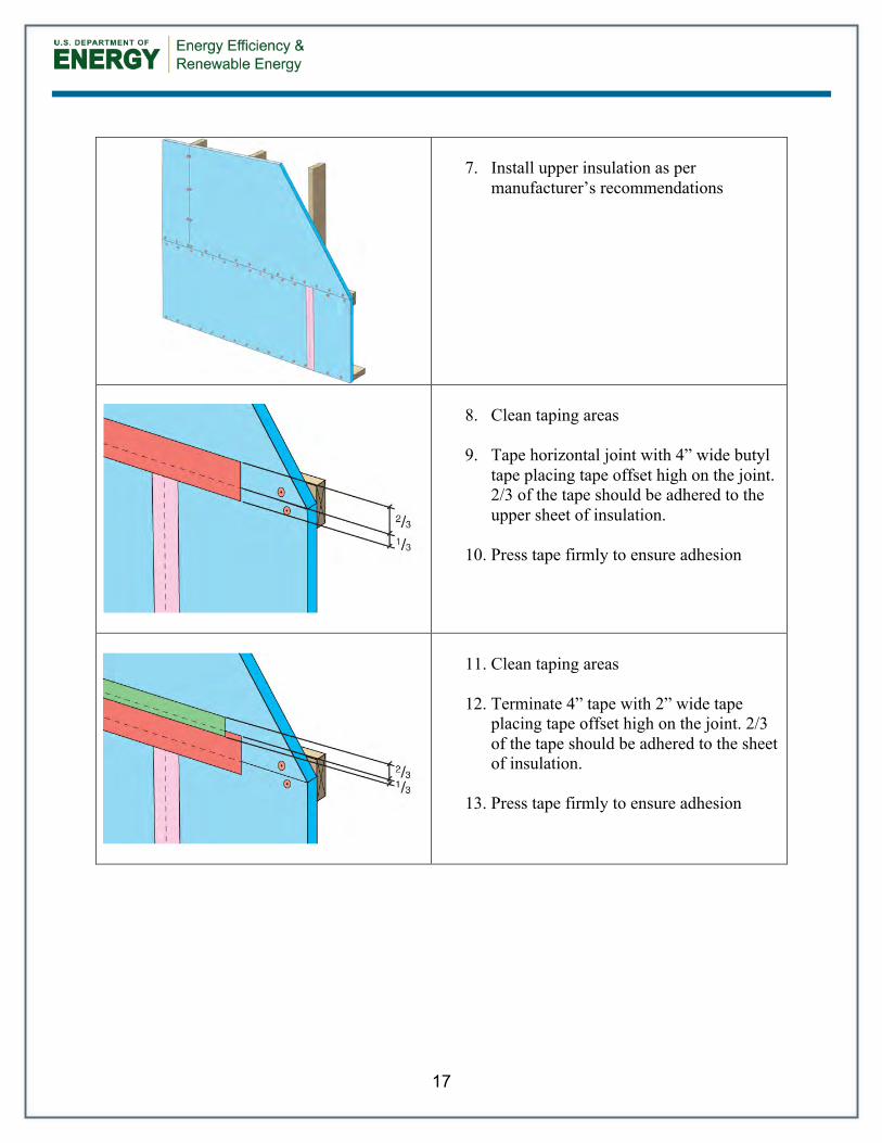
7. Install upper insulation as per
manufacturer’s recommendations
8. Clean taping areas
9. Tape horizontal joint with 4” wide butyl
tape placing tape offset high on the joint. 2/3 of the tape should be adhered to the upper sheet of insulation.
10. Press tape firmly to ensure adhesion
11. Clean taping areas
12. Terminate 4” tape with 2” wide tape
placing tape offset high on the joint. 2/3 of the tape should be adhered to the sheet of insulation.
13. Press tape firmly to ensure adhesion

18
14. Clean taping areas
15. Install 3” tape on vertical joint of upper
insulation overlapping the horizontal joint.
16. Press tape firmly to ensure adhesion
17. Wall is now ready for exterior cladding
installation

19
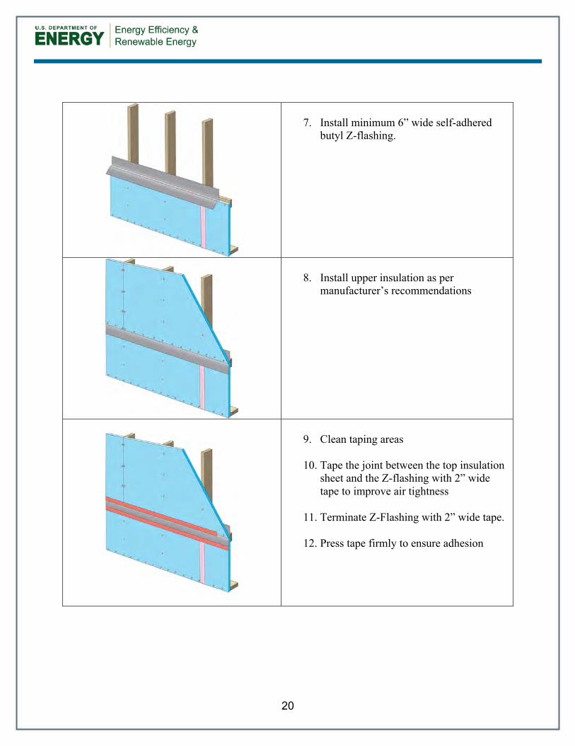
BEST – Z-Flashed Exterior Insulation Drainage Plane
Steps 1 - 16
1. Frame wall
2. Install horizontal blocking where joints in the exterior insulation will exist
3. Install lower insulation as per
manufacturer’s recommendations
4. Clean taping areas
5. Install 3” tape on vertical joint of lower
insulation
6. Press tape firmly to ensure adhesion
20
7. Install minimum 6” wide self-adhered
butyl Z-flashing.
8. Install upper insulation as per
manufacturer’s recommendations
9. Clean taping areas
10. Tape the joint between the top insulation
sheet and the Z-flashing with 2” wide tape to improve air tightness
11. Terminate Z-Flashing with 2” wide tape.
12. Press tape firmly to ensure adhesion
21
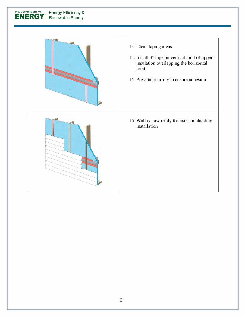
13. Clean taping areas
14. Install 3” tape on vertical joint of upper
insulation overlapping the horizontal joint
15. Press tape firmly to ensure adhesion
16. Wall is now ready for exterior cladding
installation

22
6 Summary
Questions 1 and 2 - What materials are available for this purpose? What are the characteristics of these materials? Which new materials meet the performance requirements for water management with insulating sheathing? Answer.
• A superior thin tape is: o Acrylic adhesive based o Available in wide widths up to 4” o Through experience be able to adhere to almost any substrate with high reliability
in a range of climatic situations o Have good temperature and UV resistance o Available nationwide at a competitive price
• A superior flashing tape is: o Butyl adhesive based o Not more than 20 mil thick (ensures overlaps do not build-up too much) o Available in 6, 9, and 12” widths o Have a facer that is very expansion/contraction compatible with its adhesive
substrate o Have a facer that is no wider than the adhesive as to not trap water o Through experience be able to adhere to almost any substrate with high reliability
in a range of climatic situations o Have good temperature and UV resistance o Available nationwide at a competitive price
Question 3 - What is the experience of installers in all climates? Answers: The following are best practice and product recommendations from the interviewed contractors and homebuilders who collectively have a vast amount of experience. Three items are required to make taped insulating sheathing a simple, long term, and durable drainage plane:
1. Horizontal joints should be limited or eliminated wherever possible 2. Where a horizontal joint exists use high quality materials 3. Frequent installation inspection and regular trade training are required
The following is a summary of the homebuilder’s opinions and recommendations on methods and products:
• On horizontal joints, the tape should be offset favoring more tape on the upper sheet of substrate. A decent rule is that 2/3 of the tape should be on the top sheet, and the remainder lapped over the bottom sheet
23
• Z-flashings can be used on all horizontal joints and should be used on any high-risk horizontal joint
• Drainage planes and tapes must be smooth, clean, dust free, and ideally warm • A termination strip of thin tape should always be used for thick tapes • Backup wood blocking should be installed behind horizontal joint locations • Vertical joints should land on framing members and be taped with a minimum 3” wide
acrylic tape and gravity lapped with the horizontal joint • In terms of flashing tapes, almost all groups interviewed prefer butyl based tapes over
asphaltic based tapes • Dow Weathermate is an thin tape product that was recommended by most homebuilders • Dow Weathermate Flashing is a flashing tape product that was recommended by most
homebuilders
24
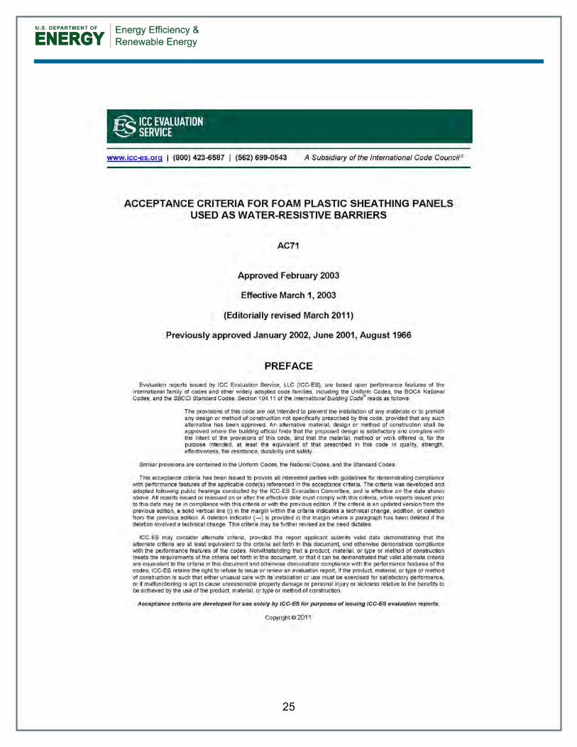
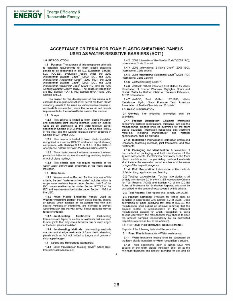
Attachment A: Compliance
International Code Council Evaluation Service – AC71 – Acceptance Criteria for Foam Plastic Sheathing Panels Used as Water-Resistive Barriers
25
26

27

28

29
Attachment B: Product Materials
Dow Weathermate Tape, Weathermate Flashing Tape, and Foil Tapes Link – http://building.dow.com/na/en/products/specialty/accessories.htm Dupont Tyvek Tape and Straightflash Link – http://www2.dupont.com/Tyvek_Weatherization/en_US/products/residential/resi_accessories.html Henry Blueskin Tape Link – http://henry.com/airandvapor/nonpermeable/blueskinWB Typar Tape Link – http://typar.com/homeowner/products/accessories/ Tuck Tape Link – http://www.cttgroup.com/cantech/en/details/135/

30
References
Building Science Digest - 013: Rain Control in Buildings, Building Science Corporation, 2006, www.buildingscience.com, accessed July 2012 Building Science Digest - 105: Understanding Drainage Planes, Building Science Corporation, 2006, www.buildingscience.com, accessed July 2012 Building Science Digest - 144: Increasing the Durability of Building Constructions, Building Science Corporation, 2006, www.buildingscience.com, accessed July 2012 Building Science Corporation. (2007) “Water Management Details for Residential Buildings.” Building Science Corporation, www.buildingscience.com , accessed July 2012 Building Science Guides and Manuals: Water Management Details for Residential Buildings – Housewraps/Flashings/Windows, Building Science Corporation, 2007, www.buildingscience.com, accessed July 2012 Building Science Information Sheet - 303: Common Flashing Details, Building Science Corporation, 2009, www.buildingscience.com, accessed July 2012 ICBO Evaluation Service, Inc. (2001) “Acceptance Criteria for Flashing Materials” AC148, Whittier, CA. ICC Evaluation Service, Inc. (2003) “Interim Criteria for Foam Plastic Sheathing Panels Used As Weather-Resistive Barriers” AC71, Whittier, CA. Lstiburek, J.W. (January 2010). “Building Sciences: Mind the Gap, Eh?.” ASHRAE Journal (vol. 52); pp. 57-63. Lstiburek, Joseph. (2006) Water Management Guide. Building Science Press: Westford, MA.

31
Appendix A – Homebuilder Interviews
Six homebuilders were interviewed who represent the experience of building over 27,000 homes in 2011. Builders were asked the following questions and BSC facilitated the discussions that followed. The findings were the basis for the Best Practices and Construction Details sections within the measure guideline.
• Do you use taped insulating sheathing as the drainage plane? • Do you build your walls with two drainage planes or one? • What materials have you used as your drainage planes? • How long have you been using taped drainage planes? • Have you had call backs related to failures? If yes, what did you find? If no, have you
ever removed siding to see if it is still sticking? • How come you have never used taped sheathing? • Do you want to learn how to use taped insulating sheathing? • Have you ever had issues with tape sticking to sheathing? • What do you do to make tape stick to insulating sheathing? • What tapes do you use? • Have you ever switched manufacturers? • Is there a manufacturer that you prefer? • Do you always pair the insulating sheathing with the tape made for that sheathing? • What insulating sheathing manufacturers do you use? • Have you ever used self-adhered self-sealing membrane materials? • Do you use termination mastics or tapes? • What widths of tapes have you tried? • Have you ever tried flashing the joints of the insulating sheathing? • Do you integrate sub sill flashings for all openings?

32
Appendix B: Future Research - Exposure Rack Recommendation Verification
The purpose of constructing the exposure rack is to determine the best performing tapes and tape systems under harsh conditions while implementing some of the best practices and materials as recommended by the interviewed homebuilders. The theory would be that the best performing tape or system on the exposure rack would not perform any worse behind a protective cladding and would likely perform better. Exposure Rack Design The rack was tilted to 75 degrees from horizontal vs the normal 90 degrees to horizontal that a wall would stand. This lean increases incidental rain and night sky radiation based cooling, thereby increasing the severity of the weather conditions experienced by the tapes and systems. An overhang is not provided to help ensure all of the samples experience similar wetting. Gaps are left between the samples to help ensure the lower samples do not see the run-off from the upper samples. The panels are raised off the platform by 24” to limit the splash-back on the lower samples. The rack system is to be faced South for maximum solar exposure (both thermal cycling and degradation), but it is built on a mobile platform so that other orientations can be tested if desired. The test rack has been located in a Zone 5 climate in an exposed location away from shading. Three 4’x8’ panels were built on 10’ tall racks and tilted back to 75 degrees from horizontal. The West panel has 8 horizontal joint samples while the center and East panels have 20 panels each for a total of 48 tested joints. The West panel tests have an 11” x 22” upper and lower section of insulation joined at the middle by a tape (Figure 16). The center and East panels have a 9” x 11” upper and lower section of insulation joined at the middle by a tape (Figure 17). All panels have 6” on center cap-nail fasteners at the perimeter where the tape is applied as required by the insulation manufacturer. The tape is not shown in the drawings as the tape width, color, and translucence vary by manufacturer. The intention of having two different sized panels is to allow the tape to experience two different expansion and contraction tests. The panel layouts are shown in Figure 18 and Figure 19. The tapes include acrylic, asphalt, and butyl adhesives and a range of facer materials and widths. Some tapes were installed and tested in combination.

33
Figure 16 - West Test Panels
Figure 17 - Center and East Test Panels

34
Figure 18 - West Test Panel Layout
Figure 19 - Center and East Panel Layout
Error! Not a valid link.

35
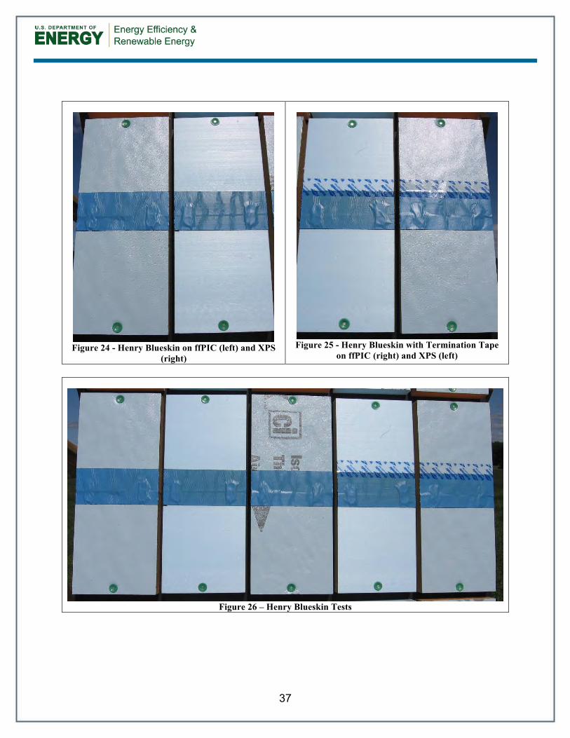
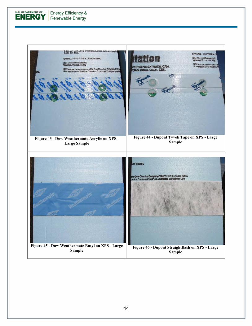
Exposure Rack Testing The following photos show the exposure rack built as the follow-up experiment to the contractor’s recommendations. Key items monitored over the long-term testing period will be visible changes in the surface characteristics, inspection for peeling or curling, lack of long-term adherence, and differences between tape material performance on XPS or ffPIC substrates. XPS and ffPIC insulation were considered because they can be used as a drainage plane. As this is a long-term test, no results are available at this time. These figures (Figure 20 through Figure 50) show the tapes within 7 days of installation. All tapes were installed on clean, warm, dry, dust free surfaces at approximately 75°F. Each tape was pressed into the surface by hand as recommended by the homebuilders.
Figure 20 - Full Exposure Test Platform

36
Figure 21 - Typar Tape on ffPIC (left) and XPS
(right)
Figure 22 - Typar Tape with Termination Tape on
ffPIC (right) and XPS (left)
Figure 23 - Typar Tests
37
Figure 24 - Henry Blueskin on ffPIC (left) and XPS
(right)
Figure 25 - Henry Blueskin with Termination Tape
on ffPIC (right) and XPS (left)
Figure 26 – Henry Blueskin Tests
38
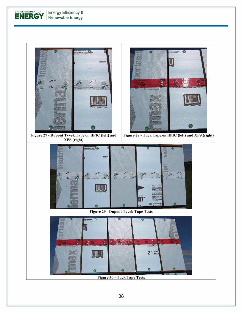
Figure 27 - Dupont Tyvek Tape on ffPIC (left) and
XPS (right)
Figure 28 - Tuck Tape on ffPIC (left) and XPS (right)
Figure 29 - Dupont Tyvek Tape Tests
Figure 30 - Tuck Tape Tests

39
Figure 31 - Dupont Straightflash Tape on ffPIC (left) and XPS (right)
Figure 32 - Dupont Straightflash Tape Tests

40
Figure 33 – Dow Weathermate Butyl with Termination Tape on ffPIC (left) and XPS (right)
Figure 34 - Dow Weathermate Butyl with Termination Tape Tests

41
Figure 35 – Dow Weathermate Butyl on ffPIC (left) and XPS (right)
Figure 36 - Dow Weathermate Butyl Tests
42
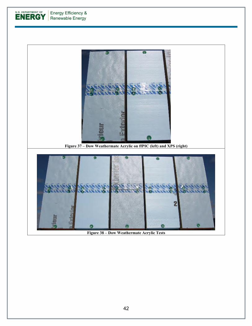
Figure 37 – Dow Weathermate Acrylic on ffPIC (left) and XPS (right)
Figure 38 – Dow Weathermate Acrylic Tests
43
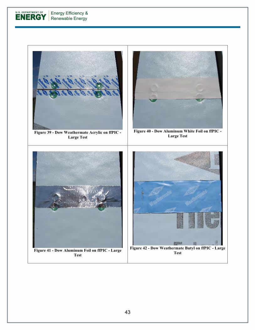
Figure 39 - Dow Weathermate Acrylic on ffPIC -
Large Test
Figure 40 - Dow Aluminum White Foil on ffPIC -
Large Test
Figure 41 - Dow Aluminum Foil on ffPIC - Large
Test
Figure 42 - Dow Weathermate Butyl on ffPIC - Large
Test
44
Figure 43 - Dow Weathermate Acrylic on XPS -
Large Sample
Figure 44 - Dupont Tyvek Tape on XPS - Large
Sample
Figure 45 - Dow Weathermate Butyl on XPS - Large
Sample
Figure 46 - Dupont Straightflash on XPS - Large
Sample

45
Figure 47 – West Large Sample Tests Upper
Figure 48 – West Large Sample Tests Lower

46
Figure 49 - Center Small Sample Tests

47
Figure 50 - East Small Sample Tests

DOE/GO- KNDJ-1-40337-02 ▪ October, 2012
Printed with a renewable-source ink on paper containing at least 50% wastepaper, including 10% post-consumer waste.

RR-1301: Guidance on Taped Insulating Sheathing Drainage Planes: Final Report
About the Authors
Direct all correspondence to: Building Science Corporation, 30 Forest Street, Somerville, MA 02143.
Limits of Liability and Disclaimer of Warranty:
Building Science documents are intended for professionals. The author and the publisher of this article have used their best efforts to provide accurate and authoritative information in regard to the subject matter covered. The author and publisher make no warranty of any kind, expressed or implied, with regard to the information contained in this article.
The information presented in this article must be used with care by professionals who understand the implications of what they are doing. If professional advice or other expert assistance is required, the services of a competent professional shall be sought. The author and publisher shall not be liable in the event of incidental or consequential damages in connection with, or arising from, the use of the information contained within this Building Science document.
Joseph Lstiburek, Ph.D., P.Eng., is a principal of Building Science Corporation inSomerville, Massachusetts. Joe is an ASHRAE Fellow and an internationally recognizedauthority on indoor air quality, moisture, and condensation in buildings. More informa-tion about Joseph Lstiburek can be found at www.joelstiburek.com.
Aaron Grin is a building scientist and researcher with a background in structural Civil Engineering. More information about Aaron Grin can be found at www.buildingscienceconsulting.com