Guidance notes on the design, construction, approval and ...
65
Technical Services Partnership Witham Park House Waterside South, Lincoln, LN5 7JN Tel CSC: (01522) 782070 Fax: (01522) 516716 E-mail: [email protected] Guidance notes on the design, construction,
Transcript of Guidance notes on the design, construction, approval and ...

Technical Services Partnership Witham Park House Waterside South, Lincoln, LN5 7JN Tel CSC: (01522) 782070 Fax: (01522) 516716 E-mail: [email protected]
Guidance notes on the design, construction, approval and drawing standards for projects
on Lincolnshire highways

LincolnshireCOUNTY COUNCIL
LincolnshireCOUNTY COUNCIL
HIGHWAYS ALLIANCE
Note: This information is held digitally in a live time system. If you are reading this on printed media, there is a risk it may not be current. Please check for updates.
Summary of Contents
General Introduction Roads Structures Street Lighting Traffic Signals Signs & Lines
Cross Discipline Topics Drawing Standards (NB Detail not included in CPO information as not relied on for design) CAD User Guide (NB Detail not included in CPO information as not relied on for design) Road Safety Audits
Exception Reports Departures from Standard Traffic Regulation Orders Considerations in Design Typical Details Site Supervision (NB Detail not included in CPO information as not relied on for design) Considerations in Construction (NB Detail not included in CPO information as not relied on for design)

Note: This information is held digitally in a live time system. If you are reading this on printed media, there is a risk it may not be current. Please check for updates.
General Introduction
This design Guide is intended to provide guidance on the design and
construction of highways within Lincolnshire. It is intended that this document is for the use of anyone involved in this type of work.
This is a live document and is held electronically – if you are reading this on
printed media there is a risk it may not be current. Please check for updates.

Technical Services Partnership Roads Design Guide
Note: This information is held digitally in a live time system. If you are reading this on printed media, there is a risk it may not be current. Please check for updates.
LincolnshireCOUNTY COUNCIL
LincolnshireCOUNTY COUNCIL
HIGHWAYS ALLIANCE
Roads Contents
INTRODUCTION AND BACKGROUND
Definitions
HIGHWAY DESIGN
Junction Design
Highway Alignment
Horizontal Design Vertical Design
Design of Roundabouts
Design of Mini Roundabouts
Design of Footways
Design of Cycleways
Highway Construction
Highway Drainage Design – Sealed
Design of Bus Stops
SURVEY EQUIPMENT CALIBRATION
OTHER SOURCES OF INFORMATION

Technical Services Partnership Roads Design Guide
Note: This information is held digitally in a live time system. If you are reading this on printed media, there is a risk it may not be current. Please check for updates.
Introduction and Background
Introduction The TSP Roads Team Design Guide has been produced to provide help with the selection of the appropriate design standards for the projects being undertaken within Technical Services Partnership. It is not intended for the guide to replace any of the standards that the County Council has adopted, but it will provide guidance on their application. The guide has been broken down into sections: - Surveys (Data Gathering) Highway Design Preparation of Contracts Statutory Processes This document is a live publication and is only current at the time of use. The user should not print off copies of any of the guidance notes and continue to refer to them, but rather should access the information as new from the web based master copy.
Background The guide has been developed from the original work instructions first developed some years ago. Once the subject covered has been introduced into the guide the relevant work instruction will be withdrawn. All copies held by users of the work instructions should be destroyed. HAT 34, defines the Principal Documents used by the County Council in controlling the standards used in the design of schemes.
Back to contents page

Technical Services Partnership Roads Design Guide
Note: This information is held digitally in a live time system. If you are reading this on printed media, there is a risk it may not be current. Please check for updates.
Definitions
HIGHWAY – the public road system including all elements that makes the system safe
and usable including bridges, lighting, drainage, signing and markings etc ROAD – the adopted carriageway and associated footways ESTATE ROAD – a carriageway constructed by a private concern on private land normally
with a view to it being adopted DRAINAGE SYSTEM – a combination of a number of drain runs and chambers to remove
rain water from a large or complex area DRAINAGE – the provision of localised drainage such as a gully and outfall pipe CAD – computer aided design / drafting [Note: “aided”, computers do not design or draw,
they only aid the user] S38 – a legal agreement between the Highway Authority and a private developer to enable
an estate road to be adopted S278 – a legal agreement between the Highway Authority and another party to enable
work to be done within the Highway that will be to the benefit of both the public and the other party
Back to contents page

Technical Services Partnership Roads Design Guide
Note: This information is held digitally in a live time system. If you are reading this on printed media, there is a risk it may not be current. Please check for updates.
Highway Design
Junction Design Author R. D. May
Scope The guide covers all aspects of junction design, including the design of simple major/minor priority junctions through to grade separated junctions. It does not cover the design of roundabouts or signalised junctions. Standards Subject to the contents of HAT 34 the following standards may be applicable, the latest version of which should be useless otherwise stated. (NOTE: Documents not contained in HAT 34, such as new standards, may be of relevance to some schemes.)
TD9 Highway link Design link to document
TD42 Major/Minor junctions link to document
TD22 Layout of Grade Separated Junctions link to document
TD40 Layout of Compact Grade Separated Junctions link to document
Development Road Guide link to document
Disability Advice link to document
TD41 Access on to Trunk Roads [junctions below 500AADT] link to document
HAT 30 County Council policy on Cycle provision link to document Application All junctions shall where practical comply with the relevant standards set out above. For all principal and classified (non estate roads) junctions should be designed to conform to the standards set out in TD9, TD42, TD22, TD40 and TD41 as appropriate. For estate roads the standards set out in the development road guide shall be used. The designer should note that where the estate makes a junction with the classified road network it should be designed in accordance with TD42 or other relevant national guidance and not to the development road guide.

Technical Services Partnership Roads Design Guide
Note: This information is held digitally in a live time system. If you are reading this on printed media, there is a risk it may not be current. Please check for updates.
Notes/Guidance
Designers will need to take into account the following: -
TD42 or any of the other TDs should not be read in isolation. TD9 gives a great deal of guidance on the application of design standards and the various criteria that need to be considered.
Adequate visibility is crucial to the safe operation of any junction, too great a visibility can have a detrimental impact. Particular note should be paid to TD9 paragraph 1.26.
TD42, as with many of the national design guides, focuses on the design of the carriageway for motorised traffic and pays little attention to other road users such as pedestrians and cyclists. The designer will need to consider whether the junction is likely to be used by cyclist and/or pedestrians and if so the likely level of usage that will need to be taken into account.
Particular attention to the provision of safe crossing points, especially for the less able needs to be considered. The crossing points should be located as near to the desired lines as possible. Location away from the desired lines will reduce the effectiveness of the provision.
The designer should always consider the capacity of the junction at the time of construction, but also will need to take into account future traffic demands. Guidance on the choice of junctions is set out in TD42 and TD 41. If capacity is an issue then layout capacity should be tested using PICADY, a programme that will calculate the capacity of a junction.
Many junctions will reside on abnormal road routes. Reference to TSP structures section should be made before finalising any design options.
Advice should be requested from specialist engineers regarding lighting, signs etc.
Back to contents page

Technical Services Partnership Roads Design Guide
Note: This information is held digitally in a live time system. If you are reading this on printed media, there is a risk it may not be current. Please check for updates.
Highway Alignment Author: R. D. May
Scope The Design guide covers the design of the horizontal and vertical alignment of carriageways. Standards Subject to the contents of HAT 34 the following standards may be applicable, the latest version of which should be useless otherwise stated. (NOTE: Documents not contained in HAT 34, such as new standards, may be of relevance to some schemes.)
TD9 Highway link Design link to document
Development Road Specification link to document
Disability Advice link to document
Guidance on the use of Tactile Paving Surfaces link to document
HAT 30 County Council policy on Cycle provision link to document
TD27 Cross-Sections and Headrooms link to document Application The horizontal and vertical alignment of links (the section of carriageway between junctions) shall comply where possible with the relevant standards set out above. For all principal and classified (non estate roads) all links should be designed to conform to the standards set out in TD9. Further guidance is given in the Maintenance Manual and is applicable to minor improvements of existing roads. For estate roads the standards set out in the development road guide should be used. The designer should note that where the development forms an improvement of the existing classified road network it shall be designed in accordance with TD9 and not to the development road guide.

Technical Services Partnership Roads Design Guide
Note: This information is held digitally in a live time system. If you are reading this on printed media, there is a risk it may not be current. Please check for updates.
Notes/Guidance Designers will need to take into account the following: -
TD9 or any of the other TDs should not be read in isolation. TD9 gives a great deal of guidance on the application of design standards and the various criteria that need to be considered.
Adequate visibility is crucial to the safe operation of any highway. Particular note should be paid to TD9 paragraph 1.26.
TD9, as with many of the national design guides, focuses on the design of the carriageway for motorised traffic and pays little attention to other road users such as pedestrians and cyclists. The designer will need to consider whether the links are likely to be used by cyclists and/or pedestrians and if so the potential level of usage that will need to be taken into account.
Particular attention to the provision of safe crossing points, especially for the less able needs to be considered. The crossing points should be located as near to the desire lines as possible. Location away from the desire lines will reduce the effectiveness of the provision.
The designer should always consider the capacity of the links, both at time of construction, but also will need to take into account future traffic demands.
Many links will form part of abnormal road routes. Reference to TSP structures section should be made before finalising any design.
Advice should be requested from specialist engineers regarding lighting, signs etc.
Horizontal Design
Whilst the design of an arc can be simple, most alignments will require the application of transitions. Use of transitions will have a significant impact upon the plan location of the arc. This is an important consideration especially when assessing the feasibility of an alignment. In most cases initial alignments should be manually designed and developed using MX design software. Layouts drafted in AutoCad are not generally adequate and should be used only where the alterations are minor. Manual design can be appropriate in some cases, certainly initially. REMEMBER, the final horizontal design must tie in with the existing alignments at either end regardless of the effect this has on the new design.

Technical Services Partnership Roads Design Guide
Note: This information is held digitally in a live time system. If you are reading this on printed media, there is a risk it may not be current. Please check for updates.
Vertical Design
MX uses the M value in calculating the vertical alignment of the carriageway. TD9 uses K values. K = L/(a-b) where L is the length of the vertical curve, a = the gradient at the start of the vertical curve (expressed as a percentage) and b = the gradient at the end of the vertical curve (expressed as a percentage). M = 100/K For example TD9 gives the minimum crest K value for stopping sight distance (SSD) of a 100 kph road as 100. Therefore: - M = 100/K = 100/100 = 1 Manual design can be appropriate in some cases, certainly initially. REMEMBER, the final vertical design must tie in with the existing alignments at either end regardless of the effect this has on the new design.
Back to contents page

Technical Services Partnership Roads Design Guide
Note: This information is held digitally in a live time system. If you are reading this on printed media, there is a risk it may not be current. Please check for updates.
Design of Roundabouts Author: R. D. May
Scope The guide covers all aspects of roundabout design, excluding the design of mini roundabouts. Standards Subject to the contents of HAT 34 the following standards may be applicable, the latest version of which should be useless otherwise stated. (NOTE: Documents not contained in HAT 34, such as new standards, may be of relevance to some schemes.)
TD9 Highway link Design link to document
TD16 Geometric Design of Roundabouts link to document
Disability Advice link to document
Guidance on the use of Tactile Paving Surfaces link to document
HAT30 County Council policy on Cycle provision link to document Application All roundabouts should comply with the standards set out above. S278 schemes shall also be subject to these standards unless a relaxation or departure is approved. Notes/Guidance Designers will need to take into account the following: -
TD16 or any of the other TDs should not be read in isolation. TD9 gives a great deal of guidance on the application of design standards and the various criteria that need to be considered.
Adequate visibility is crucial to the safe operation of any roundabout, too great a visibility can have a detrimental impact. Particular note should be paid to TD9 paragraph 1.26.
TD16, as with many of the national design guides, focuses on the design of the carriageway for motorised traffic and pays little attention to other road users such as pedestrians and cyclists. The designer will need to consider whether the

Technical Services Partnership Roads Design Guide
Note: This information is held digitally in a live time system. If you are reading this on printed media, there is a risk it may not be current. Please check for updates.
roundabout is likely to be used by cyclists and/or pedestrians and if so the likely level of usage that will need to be taken into account.
Particular attention to the provision of safe crossing points, especially for the less able needs to be considered. The crossing points should be located as near to the desire lines as possible. Location away from the desire lines will reduce the effectiveness of the provision.
The designer should always consider the capacity of the junction, both at time of construction, but also will need to take into account future traffic demands. Guidance is set out in TD16. If capacity is an issue then layout capacity should be tested using ARCADY, a programme that will calculate the capacity of a Roundabout.
Many roundabouts will reside on abnormal road routes. Reference to TSP structures section should be made before finalising any design options.
Roundabouts will only operate safely if the geometric properties restrict the vehicle speeds at entry. Deflection requirements shall apply to all roundabout approaches; this is because it is essential to regulate vehicle speed before entry and not whilst on the roundabout.
As a general rule it is difficult to achieve adequate deflection on roundabouts of less than 40m diameter (single carriageway approaches) and 80m (dual carriageway approaches).
Landscape designers are particularly keen to plant up the centre of roundabouts. Designers must ensure that the mature size of and proposed planting is taken into account to ensure that the planting does not encroach into the visibility envelopes. Works of art, particularly mobile features should not be sited on the central islands as these can easily distract drivers.
Safety fencing and signing should be sited with care to ensure that sight lines are not obstructed.
Care will need to be taken with the design of the vertical alignment. Designers should be aware that sudden/steep changes in gradient are a major contributory factor to accidents at roundabouts, particular affecting large vehicles. No change in grade shall be greater than 5%.
Back to contents page

Technical Services Partnership Roads Design Guide
Note: This information is held digitally in a live time system. If you are reading this on printed media, there is a risk it may not be current. Please check for updates.
Design of Mini Roundabouts Author: R. D. May
Scope The guide covers all aspects of mini roundabout design. The design of conventional roundabouts is dealt with in D103.01 Standards Subject to the contents of HAT 34 the following standards may be applicable, the latest version of which should be useless otherwise stated. (NOTE: Documents not contained in HAT 34, such as new standards, may be of relevance to some schemes.)
TD9 Highway link Design link to document
TD16 Geometric Design of Roundabouts link to document
TD54 Design of Mini-Roundabouts link to document
Mini Roundabouts Good Practice Guide (MRGPG) link to document
Disability Advice link to document
Guidance on the use of Tactile Paving Surfaces link to document
HAT30 County Council policy on Cycle provision link to document Application All roundabouts should comply with the standards set out above. S278 schemes shall also be subject to these standards unless a relaxation or departure is approved. Mini roundabouts shall not be used on roads that have a speed greater than 30mph. Notes/Guidance Designers will need to take into account the following: -
TD54, Mini Roundabouts Good Practice Guide and TD16 or any of the other TDs should not be read in isolation. MRGPG and TD9 gives a great deal of guidance on the application of design standards and the various criteria that need to be considered.

Technical Services Partnership Roads Design Guide
Note: This information is held digitally in a live time system. If you are reading this on printed media, there is a risk it may not be current. Please check for updates.
Adequate visibility is crucial to the safe operation of any roundabout, too great a visibility can have a detrimental impact. Particular note should be paid to TD9/93 paragraph 1.26.
TD54, MRGPG and TD16, as with many of the national design guides, focuses on the design of the carriageway for motorised traffic and pays little attention to other road users such as pedestrians and cyclists. The designer will need to consider whether the roundabout is likely to be used by cyclists and/or pedestrians and if so the likely level of usage that will need to be taken into account.
Particular attention to the provision of safe crossing points, especially for the less able needs to be considered. The crossing points should be located as near to the desire lines as possible. Location away from the desire lines will reduce the effectiveness of the provision.
The designer should always consider the capacity of the junction, both at time of construction, but also will need to take into account future traffic demands. Guidance is set out in TD16. If capacity is an issue then layout capacity should be tested using ARCADY, a programme that will calculate the capacity of a Roundabout.
Mini roundabouts may reside on abnormal road routes. Reference to TSP structures section should be made before finalising any design options.
Mini roundabouts will only operate safely if the geometric properties restrict the vehicle speeds at entry, deflection is key to ensuring that the roundabout works safely. This can be difficult to achieve due to the nature of the sites that are usually put forward for mini roundabouts. However, the designer should always try to induce some form of deflection if at all possible.
The layout of mini roundabouts needs to be visible to the user.
Safety fencing, guard railing and signing should be sited with care to ensure that sight lines are not obstructed.
Care will need to be taken with the design of the vertical alignment. Designers should be aware that sudden/steep changes in gradient are a major contributory factor to accidents at roundabouts, particular affecting large vehicles.
Back to contents page
Technical Services Partnership Roads Design Guide
Note: This information is held digitally in a live time system. If you are reading this on printed media, there is a risk it may not be current. Please check for updates.
Design of Footways Author: R. D. May
Scope The design guide covers the design of new footways. Standards Subject to the contents of HAT 34 the following standards may be applicable, the latest version of which should be useless otherwise stated. (NOTE: Documents not contained in HAT 34, such as new standards, may be of relevance to some schemes.)
Maintenance Design Manual link to document
Guidance on the use of Tactile Paving Surfaces link to document
HAT 30 County Council policy on Cycle provision link to document
Development Road Specification link to document Application All footways should comply with the standards set out above. For all existing county roads they shall be designed to conform to the standards set out in the Highways Maintenance Design Manual, the use of tactile pavements and the County Council policy on Cycle provision (HAT 30). For estate roads the standards set out in the development road guide shall be used. Notes/Guidance Designers will need to take into account the following: -
Where possible footways should be located to the back of the verge, with a minimum gap of 1.0m between the carriageway and the footway. Smaller gaps pose an increased safety risk and it is difficult to establish a good growth of grass due to the effects of de-icing salts and poor drainage. Narrower widths should be filled with a suitable material such as block paving.
The designer will need to consider whether the footway is likely to be used by the disabled and if so the level of usage that will need to be taken into account. This may impact upon footway widths and safety provision e.g. tactile paving.

Technical Services Partnership Roads Design Guide
Note: This information is held digitally in a live time system. If you are reading this on printed media, there is a risk it may not be current. Please check for updates.
All footways should have concrete edgings, however, see Highway Maintenance Design Guide.
Footways should be designed to drain away from adjoining properties unless there is suitable drainage provided.
Traditionally footways have been designed with a 1 in 30 crossfall. Current guidance recommends that 1 in 40 be used, especially where use by the disabled (e.g. electric buggies) is likely to be a regular occurrence.
Longfall should be limited to no greater than 1 in 14.
The crossing of private accesses can cause difficulties Whilst in ideal circumstances the footway levels should not need alteration from a smooth line to cross accesses this may not be possible. In such circumstances levels should not: -
i. form a switchback profile ii. produce changes in gradient that could cause a risk of grounding vehicles.
Details of footway construction can be found in the Maintenance Design Manual and in the TD/5 series of typical details.
Care should be taken with the choice of footway materials. Designers should ensure that materials have a good slip resistance. Falls can occur when adjacent materials have different resistance to slipping. This can be a problem when working with natural materials especially when they are being specified for their aesthetic appearance rather than their physical properties.
Remember that any new footway facility must fit into the existing situation even if this does require Departure from Standards.
Back to contents page

Technical Services Partnership Roads Design Guide
Note: This information is held digitally in a live time system. If you are reading this on printed media, there is a risk it may not be current. Please check for updates.
Design of Cycleways Author: R. D. May
Scope The design guide covers the design of new cycleways and the improvement of existing facilities. Standards
Subject to the contents of HAT 34 the following standards may be applicable, the latest version of which should be used unless otherwise stated. (NOTE: Documents not contained in HAT 34, such as new standards, may be of relevance to some schemes.)
Maintenance Design Manual link to document
Guidance on the use of Tactile Paving Surfaces link to document
HAT 30 County Council policy on Cycle provision link to document
Development Road Specification link to document Application All Cycleways should comply with the standards set out above. For all existing county roads they should be designed to conform to the standards set out in the Highways Maintenance Design Manual, the use of tactile pavements and the County Council policy on Cycle provision (HAT 30). For estate roads the standards set out in the development road guide should be used. Notes/Guidance Designers will need to take into account the following: -
Where possible cycleways should be located to the back of the verge, with a minimum gap of 1.0m between the carriageway and the footway. Smaller gaps pose an increased safety risk and it is difficult to establish a good growth of grass due to the effects of de-icing salts and poor drainage. Narrower widths should be filled with a suitable material such as block paving.
All cycleways should have concrete edgings.

Technical Services Partnership Roads Design Guide
Note: This information is held digitally in a live time system. If you are reading this on printed media, there is a risk it may not be current. Please check for updates.
Cycleways should be designed to drain away from adjoining properties unless there is suitable drainage provided.
The crossing of private accesses can cause difficulties. Whilst in ideal circumstances the cycleway levels should not need alteration from a smooth line to cross accesses this may not be possible. In such circumstances levels should not:-
i. form a switchback profile ii. produce changes in gradient that cause the risk of grounding vehicles.
Details of cycleway construction can be found in the maintenance manual and in the kerbs, footways and paved areas series of typical details.
Obstructions such as Bollards and signs and lighting columns should be avoided. Where an existing footway is being upgraded existing street furniture is frequently a problem and should be moved if possible. The designer must ensure that the owner of the street furniture is made aware of its removal and that any necessary replacements are provided.
Segregation of cyclists and pedestrians should be considered whenever possible, but the hierarchy included within the county council's cycle design guide not be considered.
Where cycle lanes on existing carriageways are required the designer will need to establish whether the lane is mandatory or advisory. Mandatory lanes will require a Traffic Regulation Order.
Back to contents page

Technical Services Partnership Roads Design Guide
Note: This information is held digitally in a live time system. If you are reading this on printed media, there is a risk it may not be current. Please check for updates.
Highway Construction Author: P. A. Saxby
Scope The Design guide covers the design of the construction of carriageways. Standards Subject to the contents of HAT 34 the following standards may be applicable, the latest version of which should be useless otherwise stated. (NOTE: Documents not contained in HAT 34, such as new standards, may be of relevance to some schemes.)
Development Road Specification link to document
LCC Maintenance Design Manual link to document
IAN73/06 Design Guidance for Road Pavements link to document
HD26 Pavement Design link to document
HD36 Surfacing Materials for New and Maintenance Construction link to document Application The construction of the carriageway shall where possible comply with the relevant standards set out above. Generally:
Main roads improvements, including S278s, are designed to the HA design guides
– IAN73/06, HD26 and HD36.
Estate roads are designed to the Development Road Specification.
Maintenance works are designed to the Maintenance Design Manual.
However, requirements are scheme specific and may need to be confirmed by the
client or Divisional Highway Manager as appropriate.
Notes/Guidance Designers will need to take into account the following: -
No design guidance should be read in isolation. Back to contents page
Technical Services Partnership Roads Design Guide
Note: This information is held digitally in a live time system. If you are reading this on printed media, there is a risk it may not be current. Please check for updates.
Highway Drainage Design – Sealed Author: N. Whitfield Scope There are two elements to highway drainage design, surface and sub-surface systems. This guide is only applicable to surface systems. Lincs Lab should be consulted with respect to sub-surface drainage. Standards The following standards will apply: - (Those publications in italics are those commonly used.) Development Road Specification and Construction Guide link to document Maintenance Design Manual link to document HA 37 Hydraulic Design of Road Edge Surface Water Channels link to document HA 39 Edge of Pavement Details link to document HA40 Determination of Pipe and Bedding Combinations for Drainage Works link to
document HA 41 A/90 A Permeameter for Road Drainage Layers link to document HA 71 withdrawn – Refer to HD 45/09 link to document HA 78 Design of Outfalls for Surface Water Channels link to document HA 79 Edge of Pavement Details for Porous Asphalt Surface Courses link to document HA 83 Safety Aspects of Road Edge Drainage Features link to document HA 102 Spacing of Road Gullies link to document HA 103 Vegetative Treatment System for Highway Runoff link to document HA 104 Chamber Tops and Gully Tops for Road Drainage and Services: Installation and
Maintenance link to document HA 105 Sumpless Gullies link to document HA 106 Drainage Runoff from Natural Catchments link to document

Technical Services Partnership Roads Design Guide
Note: This information is held digitally in a live time system. If you are reading this on printed media, there is a risk it may not be current. Please check for updates.
HA107 Design of Outfall and Culvert Details link to document HA113 Combined Channel and Pipe System for Surface Water Drainage link to document HA118 Design of Soakaways link to document HA119 Grassed Surface Water Channels for Highway Runoff link to document HD 33 Surface and Sub-surface Drainage Systems for Highways link to document TA 80 Surface Drainage of Wide Carriageways link to document Relevant British Standards The following documents offer good advice, but it is not an exhaustive list: CIRIA 635 Design for Exceedance in Urban Drainage link to document CIRIA 697 The SUDS Manual link to document CIRIA 698 Site Handbook for the Construction of SUDS link to document Design and Analysis of Urban Storm Drainage; Volumes 1 – 4; The Wallingford Procedure
link to information Sewers for Adoption link to information Application All surface drainage systems whether they are for development roads, new works (bypasses etc.) or maintenance works where the Highway Authority is the client. Development roads shall comply with the standards set out in the Development Road Specification and Construction Guide. Maintenance (minor improvements to existing infrastructure) shall comply with the standards set out in the Maintenance Design Manual. All other works shall be designed in accordance with the relevant standards contained in the Design Manual for Roads and Bridges. Drainage systems for other authorities will be designed in accordance with their requirements. Notes/Guidance

Technical Services Partnership Roads Design Guide
Note: This information is held digitally in a live time system. If you are reading this on printed media, there is a risk it may not be current. Please check for updates.
The three major objectives for draining highways are: 1. The rapid removal of surface water allowing the safe passage of vehicles with minimal
nuisance; 2. To maximise the longevity of the pavement structure and associated earthworks; 3. To minimise the impact of surface water run-off on the receiving environment. Designers will need to take into account the following:
Design guidance particularly the advice in the Design Manual for Roads and Bridges which should not be read in isolation.
Check you have an outfall and confirm the ownership and any discharge restriction.
Consider how the drainage system will be maintained – i.e. personnel access, vehicle access for off highway drainage, traffic management
Any works within 9m of Environment Agency infrastructure requires their written consent.
Back to contents page

Technical Services Partnership Roads Design Guide
Note: This information is held digitally in a live time system. If you are reading this on printed media, there is a risk it may not be current. Please check for updates.
Design of Bus Stops Author: M. Wilson Scope The design guide for bus stops has been produced by Transport Services – link to document.

Technical Services Partnership Roads Design Guide
Note: This information is held digitally in a live time system. If you are reading this on printed media, there is a risk it may not be current. Please check for updates.
Survey Equipment Calibration Author: R.D. May
Scope The calibration of equipment is an essential part of the system to meeting the requirements of the QMS. Standards Subject to the contents of HAT 34 the following standards may be applicable, the latest version of which should be useless otherwise stated. (NOTE: Documents not contained in HAT 34, such as new standards, may be of relevance to some schemes.)
Survey Store Database link to document Application The dates of due calibration are all recorded within the Survey Store Database. The responsible person shall check (on a monthly basis) for equipment due for calibration. Appropriate action shall then to be taken to ensure that re calibration is carried out, before the current certification expires. Notes/Guidance Total Stations shall be sent away for calibration to: -
Back to contents page

Technical Services Partnership Roads Design Guide
Note: This information is held digitally in a live time system. If you are reading this on printed media, there is a risk it may not be current. Please check for updates.
OTHER SOURCES OF INFORMATION
• Transport Advice Portal link to site • Local Transport Notes link to site 2/09 Pedestrian Guardrailing 1/09 Signalised Roundabouts 3/08 Mixed Priority Routes 2/08 Cycle Infrastructure Design 1/08 Traffic Management & Streetscape 1/07 Traffic Calming 2/95 Design of Pedestrian Crossings • Traffic Advisory Leaflets link to site 2/09 Integration of Pedestrian Traffic Signal Control within SCOOT-UTC Systems 1/09 Compact MOVA 1/08 Wig-wag Signals 2/07 Use of Bus Lanes by Motorcycles 3/06 High Occupancy Vehicle Lanes • Traffic Management Act link to site • Parking and Traffic Regulation link to site • Street Works link to site • Good Practice Guidance link to site Puffin Crossings Mini-roundabouts Portable Vehicular Signals • Traffic Signs and Signals Traffic Signs Manual Working Drawings for Traffic Signs Traffic Signs Image Database • Urban Traffic Management and Control link to site • Manual for Streets link to site • Home Zones link to site Standard Drawing Link to Site
Back to contents page

LincolnshireCOUNTY COUNCIL
LincolnshireCOUNTY COUNCIL
HIGHWAYS ALLIANCE
Note: This information is held digitally in a live time system. If you are reading this on printed media, there is a risk it may not be current. Please check for updates.
Structures Content
Abnormal Loads (NB Detail not included in CPO information as not relied on for design)
Guidance Document Appendices A Typical Memo – Chief Constable B Typical Memo – Chief Constable C Letter to Haulier D Letter to Haulier E Form of Indemnity F Letter to Vehicle Certification Agency G Process H A Brief Guide to the Law on the Road Use of Abnormal Load Carriers
and Mobile Engineering Plant I Background and definitions (DfT)
Weight Restrictions (NB Detail not included in CPO information as not relied on for design) County Council Policy Legal Obligations Types of Weight, Height and Width Restriction Regulatory Signs and Permitted Variants
Design of Small Highway Structures Guidance notes on the design, approval, construction and adoption of small
highway structures within Lincolnshire Highways
1. Introduction 2. Design And Technical Approval 3. Other External Constraints 4. Basic Design Considerations 5. Specification 6. Culverts 7. Retaining Walls 8. Footbridges 9. Road Restraint Systems 10. As Built Drawings And Maintenance Manual Appendices A Key Documents (Code of Practice And Design Documents) B Technical Approval Requirements C Construction Tolerances
Design of Vehicle Restraint Systems Guidance on the specification of VRS on Lincolnshire Highways

small highway structures
DESIGN GUIDE
Guidance notes on the design, approval, construction and adoption of small highway
structures within Lincolnshire highways
Technical Services Partnership
Witham Park House
Waterside South,
Lincoln, LN5 7JN
Tel CSC: (01522) 782070
Fax: (01522) 516716
E-mail:

Revised: January 2010
SMALL HIGHWAY STRUCTURES Design, Construction And Technical Approval Guidance Notes
Contents
1. Introduction 2 1
2. Design And Technical Approval 4
3. Other External Constraints 5
4. Basic Design Considerations 6
5. Specification 8
6. Culverts 10
7. Retaining Walls 14
8. Footbridges 16
9. Road Restraint Systems 17 14
10. As Built Drawings And Maintenance Manual 19
Appendices
A Key Documents (Codes Of Practice And Design Documents) 20
B Technical Approval Requirements 22
C Construction Tolerances 23

SMALL HIGHWAY STRUCTURES Design, Construction And Technical Approval Guidance Notes
1.3. These notes are prepared to offer
guidance and assistance to external
organisations wishing to undertake
alterations to existing structures or
construction of new structures.
The guidance provides the guidelines for the
design and specification of small highway
structures. They are not exhaustive and
should not be treated as such. They should
be read in conjunction with the Lincolnshire
County Council “Development Road Layout
Guide and Specification” document.
The notes apply in whole to structures to be
adopted by the County Council, and in part to
structures which carry or support the
highway, but are not to be adopted (see
Section 10).
1.4. The Construction (Design and
Management) Regulations 1997 lay out
requirements for clients, CDM co-ordinators
and designers to be satisfied as to their
competence to perform the functions
required of them, and to make adequate
resources available to meet their duties
under Health and Safety Statutory
provisions.
1.1. Lincolnshire County Council, as
Highway Authority within the County are
responsible for the construction,
maintenance and repair of the majority of
highway structures. Any new structures,
additions or alterations to structures located
within the public highway network will require
the prior approval of Lincolnshire County
Council, regardless of present or future
ownership.
For the purpose of this document, a highway
structure is defined as any item of
infrastructure providing either a clear span or
retained height of 600mm or greater. This
encompasses bridges, culverts (both pipes
and concrete boxes), footbridges and
retaining walls.
1.2. The management of Lincolnshire
highway structures is undertaken by
Technical Services Partnership on behalf of
Lincolnshire County Council, all
correspondence should be addressed to:
Technical Services Partnership
Lincolnshire County Council
Witham Park
Waterside South
Lincoln
LN5 7JN
Trunk Roads are controlled by the Highways
Agency, and matters relating to these roads
must be referred to this organisation.
1. Introduction

SMALL HIGHWAY STRUCTURES Design, Construction And Technical Approval Guidance Notes
1.5. All new structures that are adopted as
public highway will require a commuted sum
to be paid to the authority for the future
inspection, maintenance and replacement of
the structure.
This commuted sum will be calculated to
cover the costs associated with the
maintenance of the structure over the next
150 years, discounted for the effects of
inflation and interest payments, and may be
significant compared to the construction cost
of the structure. The calculation of this
commuted sum will be generally in
accordance with CSS guidelines.
1.6. Any changes to the highway layout will
be subjected to a safety audit process, at
both the design and construction stages. This
will be undertaken by the Lincolnshire Road
Safety Partnership, and any matters arising
must be either attended to in the design, or
an exception report approved.
1.7. For non-adoptable small highway
structures the Highway Authority (the County
Council) is more concerned with their
strength and integrity than their durability.
The basic design considerations in section
2 apply, however the requirements with
regard to durability may be relaxed. The
requirements in other sections which affect
the strength and integrity of the structure
shall apply. Aspects of the Technical Approval process
may still apply (see paragraph 2.3)

SMALL HIGHWAY STRUCTURES Design, Construction And Technical Approval Guidance Notes
2.1. All structures are to be designed and
drawn by suitably qualified civil engineers
with a working knowledge and experience of
the design of highway structures to current
standards as referred to in Section 4 below.
2.2. Attention is drawn to the requirement
to Construction (Design and Management) Regulations 2007 in relation to assessing the
competence of designers, in both individuals
and organisations.
2.3. Design methods and procedures for
the design of highway structures are
provided in the most recently published
edition of the Highway Agency Design Manual for Roads and Bridges (commonly
referred to as DMRB).
2.4. The technical advice notes and
standards contained in this document are
adopted by Lincolnshire County Council in
their entirety, and further supplemented by
other Lincolnshire specific standards detailed
in appendix ‘A’ and requirements contained
in this document.
2.5. Reference should be made to
Lincolnshire County Council policy document
HAT34 - Design Standards And Departures For Highway Schemes (Improvements, Maintenance And Developments), which
further defines documents and policies
relevant to the design of highway
infrastructure.
2.6. The status of all Highway Agency
published Interim Advice Notes (IAN’s)
should be confirmed with the TAA prior to
their inclusion within the design.
2.7. Authorisation must be obtained from
Technical Services Partnership for all
highway structures prior to commencement of
construction, including those subsequently
offered for adoption. Retrospective approval
may not be granted, and in such situations
Lincolnshire County Council as Highway
Authority may refuse to adopt the structure.
2.8. For non-adoptable highway structures
the Highway Authority will decide what part of
the Technical Approval process will apply,
and this should be confirmed with Technical
Service Partnership.
2.9. Where the appropriate published
standards are not complied with, a Departure
from Standards submission will be required
for endorsement by the Head of Technical
Services. This submission will require the
support of the Structures Group prior to
application for endorsement. Details of the
Departure from Standards submission
process can be supplied by Technical
Service Partnership.
2.10. Designs undertaken to building codes
of practice and standards (in particular
BS8110), will not be approved and will be
returned unchecked.
2. Design And Technical Approval

SMALL HIGHWAY STRUCTURES Design, Construction And Technical Approval Guidance Notes
3. Other External Constraints
3.1. In the case of works to be carried out
in, over or adjacent to any watercourse, the
design must also be submitted to any
affected drainage authority for approval. Prior
agreement must be sought to any attached
conditions that may subsequently be
transferred onto the County Council. The
County Council will require proof that this
approval has been granted.
It is considered acceptable for the drainage
authority to request the invert of a structure
to be lowered by up to 150mm when a
structure is reconstructed. Any lowering
greater than this is considered betterment
and a contribution may be requested.
3.2. Certain species of plants and animals
are protected under the Wildlife and
Countryside Acts of 1981 and 1991. The
promoter must be aware of restrictions this
protection may have on undertaking certain
works and should dutifully discharge their
responsibilities and be able to demonstrate
such.
3.3. Many statutory bodies have plant and
equipment located within the public highway
which may affect the construction or
modification works, or affect the final
structure. This includes communication
services, pipelines, sewers and supplies.
Any such services incorporated into an
adopted structure must be installed in such a
manner that the service may be replaced
without alteration to the associated structure.
This is usually achieved with the provision of
service ducts and access chambers,
extending sufficiently beyond the extents of
the structure (including any associated safety
barriers).
Consideration should be given to providing
additional spare ducts for to allow future
services to cross the structure without
alteration. This is of particular importance
where the distance between the structure
and final surface is low.

SMALL HIGHWAY STRUCTURES Design, Construction And Technical Approval Guidance Notes
4. Basic Design Considerations
4.1. The design life for all adoptable
highway structures shall be 120 years. The
DMRB allows the use of ’at least 100 years’
for assessing the durability of concrete
elements in accordance with BS8500 et al.
4.2. In addition to complying with all
appropriate standards listed in appendix ‘A’
the designer must bear the following
additional objectives in mind.
• Safe passage for pedestrians and
vehicles
• minimisation of future maintenance
costs
• minimisation of vandalism risk
• aesthetics and harmony with
surroundings
4.3. All highway structures must be
designed for both ‘full’ HA loading and a
number of units of HB loading in accordance
with BD37. Generally, the number of HB units
appropriate to the design is as shown below,
however this should be agreed with
Technical Services Partnership.
Category ‘HB’ Loading
Major routes 45 units
A & B class
carriageways 37.5 units
Other
carriageways 30 units
4.4. Design calculations must be checked
by an independent person or group prior to
submission for approval (see notes on
technical approval). An appropriate
organisation must be selected based on the
category of structure (see BD2). The checked
calculations must include a commentary by
the checker to indicate the success of the
check.
4.5. Particular care is required when
designing supporting structures for areas
such as footways, verges etc. If there is to
be no physical barrier to prevent vehicles
from gaining access to these areas, retaining
structures must be designed for the
appropriate accidental wheel loading or
surcharge.
For simple analysis of earth pressures on
retaining structures the requirement for the
inclusion of HA and HB loading may be
replaced with a nominal live load surcharge
as BD37/01 paragraph 5.8.2.
4.6. The use of structural elements where
the durability is such that they are unable to
achieve the required 120 year design life will
require the approval of Technical Services
Partnership and will result in a significantly
increased Commuted Sum being payable.
4.7. All drawings submitted for approval
shall have levels related to Ordnance Survey
Datum Newlyn (OSDN).
SMALL HIGHWAY STRUCTURES Design, Construction And Technical Approval Guidance Notes
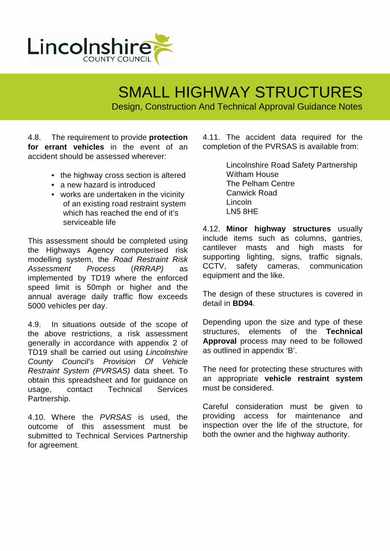
4.8. The requirement to provide protection
for errant vehicles in the event of an
accident should be assessed wherever:
• the highway cross section is altered
• a new hazard is introduced
• works are undertaken in the vicinity
of an existing road restraint system
which has reached the end of it’s
serviceable life
This assessment should be completed using
the Highways Agency computerised risk
modelling system, the Road Restraint Risk Assessment Process (RRRAP) as
implemented by TD19 where the enforced
speed limit is 50mph or higher and the
annual average daily traffic flow exceeds
5000 vehicles per day.
4.9. In situations outside of the scope of
the above restrictions, a risk assessment
generally in accordance with appendix 2 of
TD19 shall be carried out using Lincolnshire County Council’s Provision Of Vehicle Restraint System (PVRSAS) data sheet. To
obtain this spreadsheet and for guidance on
usage, contact Technical Services
Partnership.
4.10. Where the PVRSAS is used, the
outcome of this assessment must be
submitted to Technical Services Partnership
for agreement.
4.11. The accident data required for the
completion of the PVRSAS is available from:
Lincolnshire Road Safety Partnership
Witham House
The Pelham Centre
Canwick Road
Lincoln
LN5 8HE 4.12. Minor highway structures usually
include items such as columns, gantries,
cantilever masts and high masts for
supporting lighting, signs, traffic signals,
CCTV, safety cameras, communication
equipment and the like.
The design of these structures is covered in
detail in BD94.
Depending upon the size and type of these
structures, elements of the Technical
Approval process may need to be followed
as outlined in appendix ‘B’.
The need for protecting these structures with
an appropriate vehicle restraint system
must be considered.
Careful consideration must be given to
providing access for maintenance and
inspection over the life of the structure, for
both the owner and the highway authority.

SMALL HIGHWAY STRUCTURES Design, Construction And Technical Approval Guidance Notes
5. Specification
5.3.1. Concrete
The minimum requirements for structural
concrete shall be:
• Minimum strength class C32/40
• Minimum cement content 325kg/m3
• Maximum aggregate size 20mm
• Maximum free water cement ratio 0.45
Minimum cover to reinforcement shall be
40mm, including pre-cast concrete elements.
Only 1.2mm diameter stainless steel tie wire
shall be used for tying reinforcement.
All buried concrete services shall receive 2
coats of an approved below ground
waterproofing system.
5.3.2. Parapets
Anti-theft (or anti-vandal) holding down bolts
shall be provided at all vehicular and
pedestrian parapet post locations. An anti-
theft fixing shall be provided for each rail
section.
Anti-climb mesh shall be provided on the face
of post and rail type vehicular parapets
where these are located adjacent to a
footway. This mesh shall be attached in such
a manner as to facilitate simple replacement.
All steel vehicular parapets shall be painted.
5.1. The Specification for the works shall
be the latest published edition of the
Specification for Highway Works (commonly
referred to as SHW) as part of the Highways
Agency Manual Of Contract Documents For Highway Works applied in accordance with
the Notes For Guidance On The Specification For Highway Works, as modified below.
5.2. The SHW requires that items such as
concrete, waterproofing and backfill are
tested by the promoter. Proposals for
material testing items and frequency are to
be agreed with Technical Services
Partnership, and the results supplied in a
timely manner.
Failure to either complete the appropriate
testing or supply the results may affect the
authority’s decision to adopt the structure,
and will invariably lead to an increase in the
commuted sum payable.
5.3. The specification is further enhanced
by the following Lincolnshire County Council
specific additions and minimum
requirements. The requirements of the DMRB
and SHW may exceed this information, in this
instance the latter requirements shall be
complied with.
SMALL HIGHWAY STRUCTURES Design, Construction And Technical Approval Guidance Notes
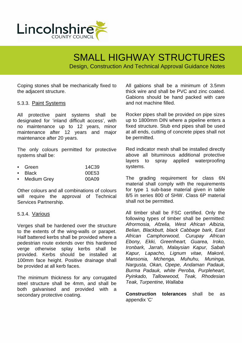
Coping stones shall be mechanically fixed to
the adjacent structure.
5.3.3. Paint Systems
All protective paint systems shall be
designated for ‘inland difficult access’, with
no maintenance up to 12 years, minor
maintenance after 12 years and major
maintenance after 20 years.
The only colours permitted for protective
systems shall be:
• Green 14C39
• Black 00E53
• Medium Grey 00A09
Other colours and all combinations of colours
will require the approval of Technical
Services Partnership.
5.3.4. Various
Verges shall be hardened over the structure
to the extents of the wing-walls or parapet.
Half battered kerbs shall be provided where a
pedestrian route extends over this hardened
verge otherwise splay kerbs shall be
provided. Kerbs should be installed at
100mm face height. Positive drainage shall
be provided at all kerb faces.
The minimum thickness for any corrugated
steel structure shall be 4mm, and shall be
both galvanised and provided with a
secondary protective coating.
All gabions shall be a minimum of 3.5mm
thick wire and shall be PVC and zinc coated.
Gabions should be hand packed with care
and not machine filled.
Rocker pipes shall be provided on pipe sizes
up to 1800mm DIN where a pipeline enters a
fixed structure. Stub end pipes shall be used
at all ends, cutting of concrete pipes shall not
be permitted.
Red indicator mesh shall be installed directly
above all bituminous additional protective
layers to spray applied waterproofing
systems.
The grading requirement for class 6N
material shall comply with the requirements
for type 1 sub-base material given in table
8/5 in series 800 of SHW. Class 6P material
shall not be permitted.
All timber shall be FSC certified. Only the
following types of timber shall be permitted:
Afrormosia, Afzelia, West African Albizia, Belian, Blackbutt, black Cabbage bark, East African Camphorwood, Curupay African Ebony, Ekki, Greenheart, Guarea, Iroko, Ironbark, Jarrah, Malaysian Kapur, Sabah Kapur, Lapacho, Lignum vitae, Makoré, Mansonia, Mchenga, Muhuhu, Muninga, Nargusta, Okan, Opepe, Andaman Padauk, Burma Padauk, white Peroba, Purpleheart, Pyinkado, Tallowwood, Teak, Rhodesian Teak, Turpentine, Wallaba
Construction tolerances shall be as
appendix ‘C’

SMALL HIGHWAY STRUCTURES Design, Construction And Technical Approval Guidance Notes
6. Culverts
6.1. General
6.1.1. The length of culvert required will be
dictated by the site geometry. Generally the
length must be sufficient to provide level
verges of not less than 2 metres width on
each side of the carriageway. In some cases
it may be preferable to increase the culvert
length to facilitate sloping batters (slope 1:1.5
maximum) and hence reduce the size of
headwalls required, or to construct
revetments.
6.1.2. The length of headwall / wingwalls
must be sufficient to accommodate a 1:1.5
batter from watercourse bed level at the side
of the culvert to verge level at the wall end.
Vertical headwalls and wingwalls should be
designed as free standing retaining walls in
accordance with section 7. Wingwalls may
be parallel to the carriageway or splayed to
suit the site topography.
As an alternative to vertical headwalls, it may
be possible to support the ground above the
structure using a revetment. These are
generally constructed, to a maximum height
of 2m, using broken kerbs and angled at a
maximum of 45°. Stone pitched or sandbag
revetments are not acceptable.
6.1.3. In the vicinity of the wing-walls,
consideration should be given to the
prevention of scour of the bank slopes,
particularly where construction work causes
removal of the natural protection provided by
established vegetation and root systems.
This can be achieved with suitable
revetments, gabions or inclusion of
reinforced soil bank slopes.
6.1.4. The culvert headwall and adjacent
watercourse should be assessed for the need
to provide vehicular containment. Where
vehicular containment is necessary, this
should be provided in accordance with
section 9.
6.1.5. In locations where the appropriate risk
assessment indicates that vehicular
containment is not required, but a pedestrian
route is present a pedestrian parapet will be
provided.
The presence of a cycleway or equestrian
route will require an appropriate increase in
the height of the parapets.
Where there is no clear pedestrian route
(neither a metalled footway nor route of a
public footpath) a white painted hardwood
timber post and two rail fence may be
provided to delineate the headwall location.

SMALL HIGHWAY STRUCTURES Design, Construction And Technical Approval Guidance Notes
As a general rule however in urban or
residential locations all drops will require
either a vehicular or pedestrian parapet.
6.1.6. If parapets or safety barriers will cause
an obstruction to visibility to either vehicles
travelling along the highway or vehicles
emerging from junctions or accesses the
culvert must be lengthened to provide wider
verges. Visibility may be provided over
safety barriers but may not be justified
through either post and rail or vertical infill
parapets.
6.2. Pre-cast Concrete Box Culverts
6.2.1. The design standard for buried
concrete box type structures is BD31. Pre-
cast box culvert units are generally designed
by the manufacturer, to the particular
intensity of highway loading appropriate to
the class of road. The depth of the culvert
below finished road level (F.R.L) must be
considered to determine the appropriate
loadings:
(a) Depth from F.R.L. to top of
culvert unit less than 0.6m:
• HA loading shall consist of the
HA UDL / KEL combination, no
dispersion either load shall be applied
• HB loading appropriate to the
road classification shall be
considered, dispersed through the fill
surfacing material
(b) Depth from F.R.L. to top of
culvert unit 0.6m or greater:
• The appropriate HB loading
only shall be applied
Account shall also be taken of a dispersed
single 100kN HA wheel load where this has a
more severe effect on the structure than the
loads described in (a) or (b) above.
6.2.2. Pre-cast concrete box culvert units on
salted routes must be designed for exposure
classes XC3 and XD2, otherwise an
exposure class of XC3 may be provided.
6.2.3. The bedding for the units is to be in
accordance with Clause 6.2.3 of BD31.
Specific consideration should be given to the
bedding for the units above a headwall base
slab.
6.2.4. If the end units are to be visible on
the completed structure façade, F4 finish fair
faced ends should be provided. The box
culvert units should be jointed and sealed
with an approved low compressibility bitumen
jointing compound, such as Tokstrip.
6.2.5. The top and sides of the units must be
waterproofed with a proprietary approved
waterproofing system down to a level
200mm below the structure soffit and up
100mm onto the headwall, wing-wall or
parapet plinth. A protective layer shall be
provided to the waterproofing system.

SMALL HIGHWAY STRUCTURES Design, Construction And Technical Approval Guidance Notes
6.2.6. Backfilling adjacent to the units is to
comprise suitable granular fill to Clause 610
of the Specification, however only class 6N
material shall be permitted. This material
shall be laid and compacted in accordance
with the Specification.
6.2.7. Fill material within 450mm of the
finished surface, including pavement and
road level is to be non-frost susceptible
granular sub-base material Type 1.
6.2.8. Where it is a requirement for the
interior of the culvert to be dry, a drainage
system to reduce pore water pressure on
the rear face of the box culvert should be
provided. Otherwise this may be omitted.
6.2.9. Consideration must be given to the
weight of pre-cast concrete box culvert units
with respect to the size of crane required for
installation.
6.3. Pre-cast Concrete Circular Pipes
6.3.1. Circular reinforced concrete pipes
suitable for installation beneath highways are
to be strength class 120. Care must be
taken to ensure the appropriate crushing
loads provided in BS5911 are used in the
pipe design.
6.3.2. Loading on pipes can be determined
from “Simplified Tables of External Loads on Buried Pipelines” published by HMSO in
1986.
6.3.3. Guidance on bedding and surround
to pipes of different sizes (up to 900mm) and
strengths is given in Department of
Environment, Transport and Regions Advice
Note HA 40.
6.3.4. Circular concrete pipes greater than
900mm diameter and having depth of cover
greater than 0.6m but less than 10.0m must
be designed to Highways Agency Standard
BD82 ‘Design of Buried Rigid Pipes’.
6.4. Corrugated Steel Buried Structures
6.4.1. Corrugated steel structures shall not
be installed within 10 miles of the coast, or
wherever other climatic conditions may affect
their longevity.
6.4.2. The suitability of this type of culvert
depends on the depth from finished road
level to soffit, which must exceed 0.65 metres
or 1/5th span (whichever is greater). They
are not acceptable in locations where the pH
value of the groundwater is less than 4.5 or
exceeds 9.
6.4.3. They are usually designed by the
manufacturer and to the particular intensity of
highway loading appropriate to the class of
road. Design and installation of corrugated
structures must be in accordance with BD 12.
Highway loading as specified in BD 37 is to
be applied to all culverts over 0.6 metres
span/diameter.
SMALL HIGHWAY STRUCTURES Design, Construction And Technical Approval Guidance Notes
6.4.4. The durability requirements are set
out in Chapter 8 of BD 12. In the absence of
appropriate soil/fill tests the Classification of
the Atmospheric Environment (Table 8) and
the Corrosivity Classification of the water or
effluent (Table 7) shall be taken as
“aggressive”.
6.4.5. The design must assume that no
maintenance repainting of the culvert will
be carried out and the inside face is therefore
designated “inaccessible”.
6.4.6. The minimum requirements for
excavation, bedding and surround of the
structures are given in Chapter 9 of BD 12.
Note that care must be exercised to ensure
an even distribution of load to either side of
the structure when backfilling.
6.4.7. In the absence of an appropriate
ground investigation report the trench width
shall not be less than three times the span or
diameter, the maximum value of Constrained
Soil Modulus used in the design shall be
20MN/m2 and the backfill shall be compacted
to not less than 85% of maximum dry density.
6.4.8. In cases where the pipe is being laid
beneath an existing carriageway and the sub-
grade material is cohesionless, the trench
width can be reduced to the minimum
required by Clause 9.5 of BD12, the design
value of Constrained Soil Modulus can be
taken as up to 33MN/mm2 and the backfill
shall be compacted to not less than 90% of
maximum dry density.
6.4.9. The finishes to the inner and outer
surfaces of the structure must be
galvanised/aluminised and provided with a
secondary protective coating by the
manufacturer prior to delivery.
6.4.10. For structures carrying water or
effluent invert protection shall be provided
using an appropriate method from Clause
8.16 of BD12/01 to protect against the effects
of abrasion/erosion.
6.5. Plastic Pipes
6.5.1. For circular culverts not exceeding
900mm diameter with a minimum cover of
1.5m on unclassified and ‘C’ class
carriageways, a plastic pipe of minimum ring
stiffness 6kN/m2 with BBÁ certification for use
as a highway drainage may be provided as a
permanent former for a structural concrete
bed and surround.
6.5.2. Care must be taken to prevent uplift
when pouring the concrete around the
pipe. This is usually achieved by strapping
down the pipe at regular intervals.
Justification will be required for the strength
capacity of the holding down straps.
6.5.3. The concrete surround must comply
with the minimum requirements for structural
concrete given in section 5 above, and must
extend a minimum of 300mm or span/2 each
side of the external face of the pipe and
500mm above the pipe.

SMALL HIGHWAY STRUCTURES Design, Construction And Technical Approval Guidance Notes
7. Retaining Walls
7.1. Design and construction
requirements for backfilled retaining walls
are given in BD30.
7.2. Highway retaining structures may be
required to perform one of two basic
functions:-
(a) To retain ground which is
elevated above the highway
and not carrying highway
loading.
(b) To retain the highway above
lower adjacent areas (e.g. wing-
walls to culverts). In this case
the wall must be able to
withstand horizontal ground
pressures imposed by traffic
loading.
7.3. Any retaining wall within 3.65m of the
public highway with a height of greater than
1.35m will require the approval of
Lincolnshire County Council (under section
167 of Highways Act 1980)
7.4. Retaining walls will frequently be of
the ‘inverted T’ form and may be
constructed of either mass concrete,
reinforced concrete or brick. Other structural
forms such as crib walls or reinforced earth
may be acceptable if designed and
constructed in accordance with all relevant
standards.
7.5. Retaining walls must be designed to
provide adequate stability against
combinations of ground forces, any possible
traffic loading and vehicular impact.
7.6. The minimum factor of safety shown
below must be provided against both sliding
and overturning. If vehicular parapets are
provided, horizontal impact loads must be
considered in assessing overall stability.
Load 1 – Active earth pressures
Load 2 – Traffic surcharge
Load 3 – Vehicular impact
Load
Combination
FOS
Sliding
FoS
Overturning
1 2 2
1 + 2 2 2
1+ 2 +3 1.5 1.5
Appropriate active and passive earth
pressure coefficients should be used in the
stability analysis.
Careful consideration should be given to any
future excavation removing a restraining
effect, as a minimum the relieving effect of
any fill material within 0.5m vertically of the
final surface should be ignored.
SMALL HIGHWAY STRUCTURES Design, Construction And Technical Approval Guidance Notes
7.12. Concrete retaining walls below
carriageway level on non-salted routes may
be designed for exposure class XC3,
otherwise exposure classes of XC3 / XD2
must be used. All concrete retaining walls
above carriageway level must be XD3.
7.13. Consideration should be given to the
appearance of concrete walls in urban and
residential environments, where the use of
brick cladding may be appropriate. Where
brick cladding is provided, this should be
attached to the supporting structure with
stainless steel fixings and any void filled with
the appropriate mortar.
7.7. In designing the integrity of structural
elements (i.e. bending and shear) the forces
due to earth pressures should be calculated
using an appropriate coefficient for earth
pressure at rest (see BS 8002 ‘Code of
Practice for Earth Retaining Structures’).
Where a retaining wall stem forms the
supporting member for a parapet it should be
designed for parapet loading in addition to
traffic loading and lateral earth pressures.
The structural analysis must consist of a limit
state design, considering both the ultimate
(ULS) and the serviceability (SLS). The
appropriate partial factors •fl, •f3, •m must be
applied for each condition.
7.8. The design must demonstrate
resistance to early thermal shrinkage of
immature concrete elements in accordance
with BA24.
7.9. Adjacent to the wall retained material
is to comprise suitable granular material to
Clause 610 of the Specification for a
minimum distance of 600mm from the wall
and is to be fully compacted in layers in
accordance with the Specification.
7.10. Where the length of wall exceeds 5
metres, consideration must be given to the
provision of joints to accommodate
shrinkage and small relative displacements
due to settlement.
7.11. Retaining structures should
incorporate suitable weep holes to relieve
pore water pressures.

SMALL HIGHWAY STRUCTURES Design, Construction And Technical Approval Guidance Notes
8. Footbridges
8.1. The span of the footbridge required
will be dictated by the site geometry. The
provision of central supports (piers) shall be
assessed on the basis of safety, appearance
and economics; generally, a single span will
provide the optimum solution.
8.2. The design criteria for footbridges
are laid out in BD29. The enhanced criteria
in Clause 14.2 of BD29 will be adopted, so
that the footbridge may be used by disabled
people. The footbridge and its constituent
parts (deck, parapets, ramps, stairs and
supports) must be designed to carry the
loads given in Section 7 of BD37.
8.3. Structural steel is to be protected
with an appropriate paint system, see section
5.
8.4. “Very Durable” structural timber (as
stated in Building Research Report No. 296)
to BS5756 and BS5268 Part 2 Grade Stress
SC8 is required, from sustained sources.
Grade Stresses shown in Table 9 of BS5268
Part 2 must be employed for the design of
timber elements.
8.5. Timber is to be planed on all sides
with the exception of deck boards. Parapet
posts and handrails are to be “Pencil
Rounded” at the corners.
8.6. In “moderate use” situations deck
boards will have anti slip grooves machined
in the saw cut face the remaining three faces
being planed. In “heavy use” situations deck
boards will require an epoxy resin bauxite
chipping type system, or similar approved
system.
8.7. The presence of a cycleway or
equestrian route will require an appropriate
increase in the height of the parapets.
Consideration must be given to items being
deliberately thrown from the footbridge onto
the area below.
8.8. Any services are to be carried by the
footbridge in a manner which gives the
minimum possible visual impact.

SMALL HIGHWAY STRUCTURES Design, Construction And Technical Approval Guidance Notes
9. Road Restraint Systems
9.1. The distance between the inside faces
of safety barriers or parapets must not be
less than 6.5 metres.
9.2. Where the appropriate risk
assessments require the provision of
vehicular containment, this may be provided
by either a parapet attached to the structure,
or a separate safety barrier. A safety barrier
does not provide protection for pedestrians,
and a further pedestrian barrier will be
required.
9.3. Safety barriers and vehicle parapets
are designated vehicle restraint systems
and the requirements for these items are
given in TD19.
9.4. The containment level and length of
need of a vehicle restraint system required
on the approach and departure to hazard are
given by the RRRAP computer programme,
subject to a minimum requirement specified
in TD19.
9.5. Vehicle restraint systems are specified
with a working width criteria. This working
width is measured from the traffic face of the
barrier and must be clear of other
obstructions, for a parapet the working width
may extend clear of the structure plinth.
9.6. The provision of crash cushions will
require the approval of Technical Services
Partnership, and may only be utilised in
exceptional circumstances.
9.7. Metal parapets will require mounting
on a suitable concrete plinth arrangement, for
vehicle parapets this will need to be a
minimum of 500mm width. Concrete parapet
plinths must be designed for exposure class
XD3. As an alternative to the requirements of
BD43 for impregnation, the plinth may be
constructed using strength class C40/50
concrete.
9.8. A parapet will require a safety barrier
to be installed at both ends, with an approved
transition between the systems. The
transition length is included in the length of
need, but generally will exceed the minimum
departure length.
9.9. Terminals shall be provided at each
end of a safety barrier. For roads with a
speed limit of 50mph or higher a class P4
energy impact absorbing terminal is required,
otherwise a class P1 terminal may be
provided.
9.10. Only vehicle restraint systems listed in
latest publication of the Highways Agency
‘HA Accepted EN1317 Compliant Road
Restraint Systems’ document will be
permitted.
9.11. Aluminium parapet systems shall not
be permitted in rural locations without prior
approval from Technical Services
Partnership.

SMALL HIGHWAY STRUCTURES Design, Construction And Technical Approval Guidance Notes
9.12. Pedestrian parapets may be of steel
construction with vertical infill and must
comply with BS 7818. As an alternative a
vertical brick wall of not more than a single
brick (215mm) thickness may be provided
and should have an appropriate stone or
concrete coping.
9.13. Steel pedestrian parapets shall be
both galvanised and painted in an
appropriate colour in urban environments,
elsewhere these parapets may be galvanised
only.
SMALL HIGHWAY STRUCTURES Design, Construction And Technical Approval Guidance Notes
10. ‘As Built’ Drawings & Maintenance Manual
10.1. A "Health and Safety File" in
accordance with The Construction (Design and Management) Regulations 2007 will be
required for all work affecting structures on
the public highway. Typically this would
include:-
(a) a brief description of the work
carried out, including key
structural principals and design
criteria;
(b) any residual hazards and
details of any hazardous
materials used;
(c) information regarding
demolition or dismantling of
the structure or installed
equipment;
(d) 'as-built' drawings
(e) general details (including
manufacturers and suppliers) of
materials used and methods
of construction;
(f) details of equipment and parts
which require maintenance,
including operating and
maintenance procedures; and
(g) details of the location and
nature of utilities and
services.
10.2. A separate health and safety file must
be prepared for each structure.
10.3. The adoption of any structure will
not be approved without the provision of
an accepted Health And Safety File.
10.4. On completion of a project or
structure, the client is required by the
Regulations to store the Health and Safety
File for the purposes of any future
maintenance or repair schemes. If the
client's interest in the structure is passed to
another body (e.g. if the Council adopts the
structure) the Health and Safety File shall
also be transferred.
10.5. If the structure is non-adoptable, then
the County Council requires a copy of the as-
built drawings of all highway structures for its
records.
SMALL HIGHWAY STRUCTURES Design, Construction And Technical Approval Guidance Notes
Note: These lists are not exhaustive and do
not contribute a Technical Approval schedule
The Design Manual for Roads and Bridges
(including BA, BD, HA, HD, TA, TD, IAN) and
Manual Of Contract Documents for Highway
Works (including SHW, NfGSHW, HCD) are
available at www.standardsforhighways.co.uk
For technical approvals
BD2 Technical Approval of Highway
Structures
For general design and loadings
BD 15 Use of BS 5400 Part 1: 1988.
BD 29 Design criteria for footbridges
BD 30 Backfilled retaining walls and bridge
abutments
BD 31 Buried concrete box type structures
BD 37 Loads for Highway Bridges
BD74 Foundations
BD82 Design of Buried Rigid Pipes
BS 5400 pt.2 Specification for loads
BS 8002 CP for Earth Retaining
Structures
BS 8004 Foundations
Simplified Tables of External Loads on
Buried Pipelines
Appendix A – Key Documents (Codes Of Practice And Design Documents)
For material specific properties
BD 12 Corrugated steel buried structures
BD 13 Use of BS 5400 Part 3: 1982
BD 24 Use of BS 5400 Part 4: 1990.
BD 28 Early Thermal Cracking of Concrete
BD 47 Waterproofing and surfacing of
…bridge decks
BS 5268 Structural Use of Timber
BS 5911 Specification for … reinforced
concrete pipes ….
BS 5400 pt.3 CP for design of steel bridges
BS 5400 pt.4 CP for design of concrete
bridges
BS 5628 Un-reinforced masonry
BS8500 Concrete … method of
specifying ….
BS7818 Pedestrian restraint systems
… in metal
For highway design and safety barriers
TD27 Cross-sections and Headroom
TD19 Road Restraint Systems
TD9 Highway Link Design
BS EN 1317 ….. Safety Barriers …..
SMALL HIGHWAY STRUCTURES Design, Construction And Technical Approval Guidance Notes
Other useful documents
Good Bridge Detailing Guide
BS8666 Scheduling ….. Reinforcement
HA Accepted EN1317 Compliant Road
Restraint Systems
(available from www.highways.gov.uk)
Road Restraint Risk Assessment Process
(available from www.highways.gov.uk. Note:
The latest version must be downloaded each
time before use)
CSS - Commuted Sums for Maintaining
Infrastructure Assets Guidance Document
(available from www.cssnet.org.uk)
Lincolnshire County Council Documents
(Available on request)
HAT34 Design Standards And Departures
For Highway Schemes
(Improvements, Maintenance And
Developments)
HAT40 Commuted sums for Maintenance
HAT51 Provision Of Vehicle Restraint
Systems (& PVRSAS)
HAT63 Safety Audits Policy and Guidance
DPD33 Traffic Management Act 2004 –
Registration of Works and Road
Space Booking System
Standard Drawings and Typical Details
(available from www.lincolnshire.gov.uk)
The Manual Of Contract Documents for
Highway Works
Specification for Highway Works
Notes for Guidance on the Specification for
Highway Works
Highway Construction Details

SMALL HIGHWAY STRUCTURES Design, Construction And Technical Approval Guidance Notes
All highway structures will require technical
approval in accordance with BD2. Each
structure type is allocated a category (0, 1, 2
or 3) which defines the technical approval
requirements for the structure. Technical
Services Partnership will act as TAA.
BD2 gives guidance on selecting a category
appropriate for the type of structure
proposed. The category of a structure should
be agreed with Technical Services
Partnership prior to the commencement of
detailed design. The category of the structure
may change as the design evolves.
A structure that does not conform to
published standards is either a category 2
or 3, this includes requirements for safety
barriers and parapet provision. Note: use of
the PVRSAS for situations beyond the scope
of the RRRAP does not contribute a
Departure from Standards.
The Approval In Principal process may be the
appropriate method for endorsing
Departures From Standards, otherwise a
separate Departure from Standard
submission will be required.
The following design certification will be
required, and must be submitted with full
design documentation as described below:
For all structures a Design Certificate will be
required for endorsement by the TAA.
For structures categories 1, 2 or 3 an
Approval In Principal will be required,
including a Technical Approval Schedule.
This shall be completed and submitted to the
TAA together with all necessary drawings
and other documents for agreement or
amendment.
For category 2 and 3 structures a Check
Certificate will also be necessary for TAA
endorsement. Category 3 structures require
this check to be completed by an
independent organisation.
The documentation accompanying the
Design and Check Certificates shall
comprise a full set of construction drawings
and full structural calculations written out in
sufficient detail as to be easily followed by a
competent engineer and including:
• Statements of principles employed in
analysis
• Clear references to clauses of
relevant design standards
• Diagrams and sketches as required
for clarity
• Input data for any computer program
utilised
• Computer output marked to indicate
results used in the calculations and
design.
Appendix B - Technical Approval Requirements

SMALL HIGHWAY STRUCTURES Design, Construction And Technical Approval Guidance Notes
Maximum deviation from line on LINE TOLERANCE
Given
Line 10m chord 20m chord 3m straight
Maximum
between
units
Other
requirements
Walls, vertical
or horizontal
± 7
mm 7 mm 7 mm 5 mm
Soffit edges ± 7
mm 10 mm 7 mm 5 mm
Copings ± 10
mm 5 mm 3 mm
± 7 mm over
complete length
being over 30m
Parapet
plinths
± 10
mm 5 mm 3 mm
Footways ± 15
mm 10 mm Width ± 7 mm
Channels ± 15
mm 10mm Width ± 5 mm
Appendix C – Construction Tolerances
Maximum acceptable construction tolerances (Y1) are specified as below:
10m or 20m chord
Y2
Specified line or level
Y1
Actual construction
Y1 – Max. deviation from line as constructed Y2 – Max. tolerance in line or level
Diagram of deviation / tolerance relationship
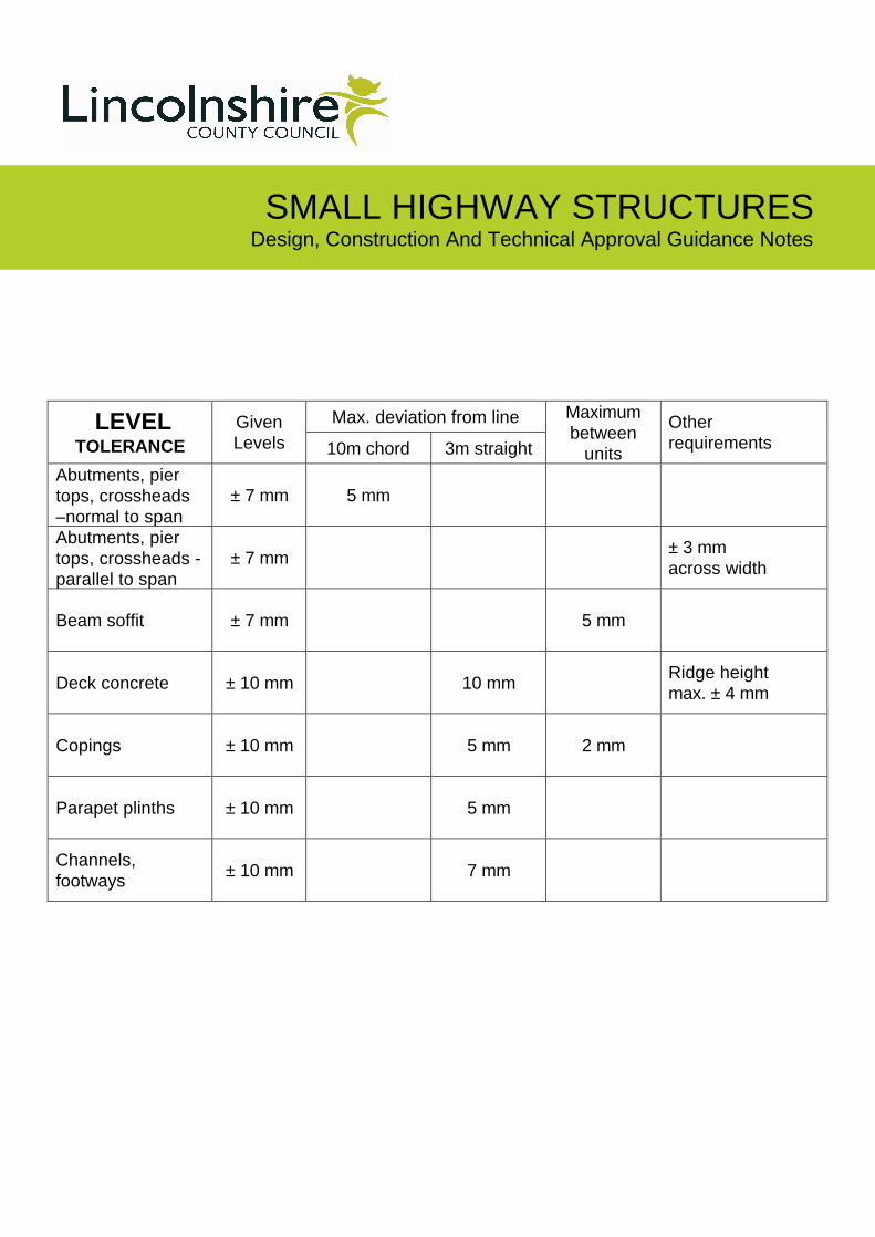
SMALL HIGHWAY STRUCTURES Design, Construction And Technical Approval Guidance Notes
Max. deviation from line LEVEL TOLERANCE
Given
Levels 10m chord 3m straight
Maximum
between
units
Other
requirements
Abutments, pier
tops, crossheads
–normal to span
± 7 mm 5 mm
Abutments, pier
tops, crossheads -
parallel to span
± 7 mm ± 3 mm
across width
Beam soffit ± 7 mm 5 mm
Deck concrete ± 10 mm 10 mm Ridge height
max. ± 4 mm
Copings ± 10 mm 5 mm 2 mm
Parapet plinths ± 10 mm 5 mm
Channels,
footways ± 10 mm 7 mm

LincolnshireCOUNTY COUNCIL
LincolnshireCOUNTY COUNCIL
HIGHWAYS ALLIANCE
Note: This information is held digitally in a live time system. If you are reading this on printed media, there is a risk it may not be current. Please check for updates.
Street Lighting Contents
General Purpose (NB Only this section included in CPO information as remainder not relied
on for design by internal teams)
Consultancy
Policy
Scope
Project Management
District Network Operators (DNO)
Requirements
Street Lighting Standards
Disconnection of Existing Lighting
Setting Out
Adoption
Specification Model Specification
Steel Columns
Hinged Columns
Lanterns
Lamps and Control Gear
Photocells
Manufacturers
Typical Details
Further Information
Appendices Sample Development Road Specification
Lanterns
Approved Equipment Manufacturers
Typical Details

Technical Services Partnership Street Lighting Design Guide General Purpose The purpose of this Guide is to provide guidance for developers and consultants who are engaged in the design of street lighting and associated equipment intended for existing or proposed highway. This document is a live publication and is only current at the time of use. The user should not print off copies of any of the guidance notes and continue to refer to them, but rather should access the information as new from the web based master copy.

Note: This information is held digitally in a live time system. If you are reading this on printed media, there is a risk it may not be current. Please check for updates.
Traffic Signals Contents
HAT 52 Traffic Signals Design Guide

LincolnshireCOUNTY COUNCIL
LincolnshireCOUNTY COUNCIL
HIGHWAYS ALLIANCE
Note: This information is held digitally in a live time system. If you are reading this on printed media, there is a risk it may not be current. Please check for updates.
Signs & Lines Contents
HAT 31 Road Markings HAT 32 Traffic Signs HAT 50 Tourism Signing Policy Passively Safe Assemblies
Risk Assessment

Technical Services Partnership Roads Design Guide
Author: R D May
Safety Audits
Scope The guide deals with the commission of Safety Audits. It does not deal with Exception Reports (D109.01) or Departures from Standards (D110.01). Standards Subject to the contents of HAT 34 the following standards may be applicable. (NOTE: Documents not contained in HAT 34, such as new standards, may be of relevance to some schemes.) HAT 62 Safety Audit Policy and Guidelines link to document Application The guide applies to all Schemes designed within the Highways Alliance. It also applies to any scheme designed by outside bodies for checking by TSP. Notes/Guidance Designers will need to take into account the following: -
All schemes designed in TSP will be subject to Safety Audit. There are three stages to Safety Audits
Stage 1 – Preliminary Stage 1 audit should be undertaken when the design has evolved sufficiently to enable progression to detailed design, but before detailed design has been undertaken. This Stage is not necessary on minor schemes.
Stage 2 – Pre Contract Stage 2 audit should be undertaken prior to tender, or in the case of a scheme being undertaken through the term maintenance contract prior to the issue of the works order.
Stage 3 – Post Construction Stage 3 audit shall be undertaken upon completion of the works on site. Completion shall mean with all street furniture, signs and lines in place.
All audits shall be undertaken by the Accident and Investigation section of the Lincolnshire Road Safety Partnership.

Technical Services Partnership Roads Design Guide
Author: R D May
Audits typically take around four weeks from the placing of the instruction with LRSP.
A detailed schedule of the information being supplied, together with a description of the works to be audited should be sent with the instruction to AIP.
The designers response to safety audits is dealt with in D109.01 Exception Reports.
Where practicable the design shall be changed in line with the recommendations of the Safety Audit.
Safety Audits do not relieve the designer of his/hers responsibilities. Designers must ensure that the design is as safe as possible within the constraints of the project.
Where the Designer has concerns over the recommendations contained in a safety audit they must discuss them initially with an independent Principal Engineer and then, if required, the Safety Auditor.
REMEMBER the Safety Audit is a public document and may be used in Legal Proceedings should things go wrong.

Technical Services Partnership Roads Design Guide
Author: R D May
Safety Audit, Exception Reports
Scope The guide deals with the production and approval of Exception Reports arising from Safety Audits. It does not deal with Safety Audits (D108.01) or Departures from Standards (D110.01). Standards Subject to the contents of HAT 34 the following standards may be applicable. (NOTE: Documents not contained in HAT 34, such as new standards, may be of relevance to some schemes.) HAT 62 Safety Audit Policy and Guidance link to document Application The guide applies to all Schemes designed within the Highways Alliance, including S278 and estate roads. Notes/Guidance Exception reports arise from the recommendations set out in a safety audit report. They are not Departures from standard. Where the matter cannot be dealt with through a design change, or alterations to the works at a stage 3 audit, the reasons and the approval of those reasons need to recorded in an Exception Report. A copy of the form to be used can be found at HAT62 Appendix C. It may be that it is not possible to meet the recommendations set out in the Safety Audit, but some measure of mitigation can be implemented. If this is the case these measures should be recorded in the report. Where the works are commissioned by the Divisional office, or is a S278 or S38 scheme then the Head of Highways for that division will need to approve the Exception Report. It is usual to discuss the need for the report and it’s recommendations prior to submission to the relevant Head of Highways. Where the work is commissioned by the capital client, the Head of Highways East will need to approve the report. All Exception Reports will be reviewed by a Principal Engineer prior to submission.

Technical Services Partnership Roads Design Guide
Author: R D May
Legitimate factors that can be taken into account when applying for an exception include practicality, cost and availability of land amongst others. It is also appropriate for the designer to disagree with the recommendation if he/she feels that it will create an additional hazard or if the designer does not believe that it will improve safety. If this is the case then the designer will need to record this in a risk assessment. It is also appropriate to apply for an exception if the recommendation addresses matters outside the scope of the works e.g. poor maintenance of existing carriageway. REMEMBER the Exception Report is a public document and may be used in Legal Proceedings should things go wrong.

Technical Services Partnership Roads Design Guide
Author: R D May
Departure from Standard Scope The guide deals with the production of and application for Departure from Standard. It does not deal with Safety Audits or Exception Reports. Standards Subject to the contents of HAT 34 the following standards may be applicable. (NOTE: Documents not contained in HAT 34, such as new standards, may be of relevance to some schemes.)
All design guides and associated materials. Application The guide applies to all Schemes designed within the Highways Alliance. The guide also applies to any schemes designed outside of Technical Services Partnership including those for checking by TSP. Notes/Guidance A Departure from Standard arises when it is not possible to meet the minimum requirements set out in the relevant design standard. The need for a departure shall be determined during the development of the design. TD9/93 gives examples of the factors that may be considered when applying for a Departure from standard. In particular reference to paragraphs 0.12 to 0.16 inclusive and paragraphs 1.15 to 1.27 inclusive gives appropriate guidance. Prior to applying for a Departure from Standards the designer shall discuss the options with a Principal Engineer who will decide whether to pursue the application. The reasons and the approval of those reasons need to be recorded in a Departure from Standard. . A copy of the form to be used can be found at HAT 34 – Appendix D. The relevant Head of Service is responsible for the approval of Departures from Standard. All Departures from Standard will be reviewed by a Principal Engineer prior to submission. The application will need to set out the following: -
The standard which cannot be met.
Alternatives considered with reasons for rejection.

Technical Services Partnership Roads Design Guide
Author: R D May
The recommended solution, including the standard that can be achieved, together
with a supporting risk assessment shall be included.
Where the client is the Head of Highways or a member of their staff and the design brief includes for a substandard design, then their instruction will be accepted as an approval to Depart from Standard except where the client in internal to Technical Services. As such a formal departure from standard signed by the relevant Head of Service will not be required. This is due to the function carried out by the Divisional Head of Highways and their staff ie: management of the local highway network and the improvement of existing facilities. However the lead design engineer should ensure that the client is aware that what they are requesting does not meet the normal standards. Safety audit must be carried out in this situation.

Technical Services Partnership Roads Design Guide
Author: R D May
Traffic Regulation Orders
Scope The guide deals with the need and implementation of Traffic Regulation Orders. It does not deal with Side Road Orders or Compulsory Purchase Orders. Standards The following standards will apply: - Application The guide covers all schemes that require an order to regulate traffic. Notes/Guidance The Highways Act defines those aspects of signing/regulation that require enforcement. Permanent Orders, examples include: -
Parking restrictions (yellow lines)
One way restrictions
Speed limits
Signalised crossings (not traffic signals)
Bus stops regulated by bus stop carriageway markings
Box junctions
Pedestrian Crossings
Temporary Orders, examples include:-
Speed Limits in Road Works
Temporary Diversion of Traffic/Temporary Road Closures
The list is not comprehensive so the designer shall establish the need for any orders during the evolution of the design and in discussion with the client/ Area Highways Office. Traffic Regulation Orders are legally enforceable orders that regulate the use of the Highway. The Order only becomes enforceable once it has been through a defined Statutory Process. Divisional staff will usually undertake this process. For schemes that
Technical Services Partnership Roads Design Guide
Author: R D May
do not originate in the divisions it is vital that Divisional Highways Manager support for the Order is obtained. This Process includes: -
Drafting of the Order and the Statement of Reasons.
Advertising/Publishing the Draft Order.
Consultation.
Application to Planning and Regulation Committee.
Implementation of the Order. Obtaining a permanent Traffic Regulation Order can take in excess of 9 months. Even though the Order may be vital to the scheme, approval by committee cannot be guaranteed.

Considerations in Design
NRSWA
Depth Proximity Detection / Measures Prevention / Alternatives
Environment
Commercial / Industrial Local Amenities Residential /Developments Elderly / Disabled Schoolchildren Pedestrians / Cyclists Town Centre
Traffic
Emergency Access Traffic Flows Traffic Speed HGV / Deliveries Traffic Management Road Widths / Safety Zones Road Closures Diversions Weight Limits Access
Construction
Structures Depths of Excavations Confined Spaces Falls from Height Contaminated Land Ground Investigation Proximity of works / Hazards Temporary Surfaces Demolition Asbestos / Lead Watercourses Adjacent Buildings Plant and Equipment Materials Noise and Dust Manual Handling Maintenance of Works
Audit Trail
Risk Reduction Recorded Design Decisions Recorded Risk Assessment Health and Safety Plan Reviews