GUIDANCE NOTES ON ROAD PAVEMENT DRAINAGE DESIGN · RD/GN/035A Guidance Notes on Road Pavement...
77
HIGHWAYS DEPARTMENT GUIDANCE NOTES ON ROAD PAVEMENT DRAINAGE DESIGN RD/GN/035A February 2020 Research & Development Division
Transcript of GUIDANCE NOTES ON ROAD PAVEMENT DRAINAGE DESIGN · RD/GN/035A Guidance Notes on Road Pavement...
HIGHWAYS DEPARTMENT
GUIDANCE NOTES
ON
ROAD PAVEMENT DRAINAGE DESIGN
RD/GN/035A February 2020
Research & Development Division
TABLE OF CONTENTS 1. Introduction ..................................................................................................................... 1 2. Background ..................................................................................................................... 1 3. Design Considerations .................................................................................................... 2
3.1 Rainfall Intensity ...................................................................................................... 2 3.2 Serviceability State Considerations .......................................................................... 5 3.3 Climatic Considerations ........................................................................................... 7 3.4 Ultimate State Considerations .................................................................................. 7 3.5 Crossfall .................................................................................................................... 9 3.6 Gully Spacing - Roads at a Gradient Greater Than 0.5% ......................................... 9 3.7 Gully Spacing - Flat or Near Flat Roads at a Gradient not Greater than 0.5% ...... 10 3.8 Design Gully Spacing and Reduction Factors ........................................................ 12
Gully Grating Efficiency ........................................................................................ 12 Blockage by Debris ................................................................................................ 13 Double Gullies ........................................................................................................ 14 Edge Drains ............................................................................................................ 14
3.9 Details to Facilitate Entry of Surface Water ........................................................... 16 Kerb Overflow Weirs ............................................................................................. 16 Gullies at Sag Points (Minimum of 4 Gullies) ....................................................... 17 Gullies Immediately Downstream of Moderate or Steep Gradients ...................... 19
3.10 Drainage at Steep Road Junction ............................................................................ 19 3.11 Other Details ........................................................................................................... 20
Footway Drainage .................................................................................................. 20 Pedestrian Crossings .............................................................................................. 20 Continuous Drainage Channel ............................................................................... 21 Gully Pots ............................................................................................................... 21 Y-junction Connection ............................................................................................ 21 Flat Channels and Pavement around Gullies .......................................................... 22
3.12 Capacity of Outlet Pipes ......................................................................................... 23 3.13 Design of Pavement Drainage in association with Steep Roads ............................ 24 3.14 Design of Pavement Drainage at Sag Sections of Expressways ............................ 25
4. Design Workflow ........................................................................................................... 26 5. Worked Examples ......................................................................................................... 28
5.1 Example 1 - Gullies in Normal Roads .................................................................... 28 5.2 Example 2 - Gullies in Expressways ...................................................................... 28 5.3 Example 3 - Gullies in flat roads ............................................................................ 29 5.4 Example 4 – Additional catchment area at road junction ....................................... 30 5.5 Example 5 – Outlet pipe for gullies at sag point .................................................... 30 5.6 Example 6 - Gullies in Normal Roads
(Design Rainfall Intensity Other than 147 mm/hr) ............................................... 31 5.7 Example 7 - Gullies in flat roads
(Design Rainfall Intensity Other than 147 mm/hr) ................................................. 31 5.8 Example 8 - Gullies at Sag Point in Expressways .................................................. 32
APPENDIX A Design of Pavement Drainage in association with Steep Roads APPENDIX B Design of Pavement Drainage at Sag Sections of Expressways
LIST OF TABLES Table 1A Maximum Rainfall Intensities and Flooded Widths for Frequent Storm Events .... 4 Table 1B Maximum Rainfall Intensities and Flooded Widths for Heavy Storm Events
(General Application) .............................................................................................. 4 Table 1C Maximum Rainfall Intensities and Flooded Widths for Heavy Storm Events
in Tai Mo Shan Area ............................................................................................... 4 Table 1D Maximum Rainfall Intensities and Flooded Widths for Heavy Storm Events
in Western Lantau Area ........................................................................................... 5 Table 1E Maximum Rainfall Intensities and Flooded Widths for Heavy Storm Events
in North District Area .............................................................................................. 5 Table 2 Design flooded widths for Normal Roads (roads other than Expressways) ........... 6 Table 3 Minimum Crossfalls ................................................................................................ 9 Table 4 Roughness Coefficients for Different Types of Road Surface .............................. 10 Table 5 Reduction Factors for Gully Efficiency ................................................................ 13 Table 6 Reduction Factors for Blockage by Debris ........................................................... 14 Table 7 Maximum Lengths (m) of Edge Drain .................................................................. 15 Table 8 Minimum Rate of Provision of Overflow Weirs ................................................... 17 Table 9 Additional Gullies at Sag Points ........................................................................... 18 Table B1 Storm Constants for 1 in 50 Years Return Period ................................................. 61 LIST OF CHARTS Design Chart 1A General Calculation of Drained Area (Gradient ≥ 0.5%) .......................... 34 Design Chart 1B Calculation of Drained Area for Hard Shoulder Flows
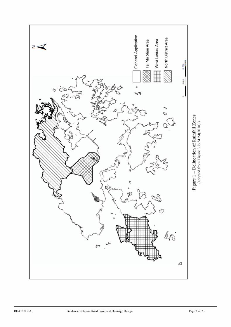
(Gradient ≥ 0.5%) ...................................................................................... 35 Design Chart 2A Gully Spacing (Lo) for Flat Roads (Gradient < 0.5%) .............................. 36 Design Chart 2B Gully Spacing (Lo), Hard Shoulder Flows (Gradient < 0.5%) .................. 37 Design Chart 3 Adjustment Factor, F (Gradient < 0.5%) .................................................. 38 Design Chart 4A R Factor, Flat Roads (Gradient < 0.5%) .................................................... 39 Design Chart 4B R Factor, Hard Shoulder Flows (Gradient < 0.5%) ................................... 40 LIST OF FIGURES Figure 1 Delineation of Rainfall Zones ................................................................................. 3 Figure 2 Typical Gully Spacing for Drained Width of 12m (unadjusted) ........................... 11 Figure 3 Specified Grating Orientation ............................................................................... 12 Figure 4 Additional Catchment Area at Road Junction ....................................................... 19 Figure A1 Flow along the Line of Greatest Slope.................................................................. 51
LIST OF SKETCHES Sketch No. 1 Edge Drain Details ...................................................................... 41 Sketch No. 2 Connection Unit between Edge Drain and Gully ........................ 42 Sketch No. 3 Slot Drain .................................................................................... 43 Sketch No. 4 Kerb Drain................................................................................... 43 HRDMISCMEL-SK0257 Drainage Inlet Across Footway / Verge (Sheet 1 of 4) ................ 54 HRDMISCMEL-SK0258 Drainage Inlet Across Footway / Verge (Sheet 2 of 4) ................ 55 HRDMISCMEL-SK0259 Drainage Inlet Across Footway / Verge (Sheet 3 of 4) ................ 56 HRDMISCMEL-SK0260 Drainage Inlet Across Footway / Verge (Sheet 4 of 4) ................ 57 HRDMISCMEL-SK0263 Intermittent Drainage Outlet at Kerb .......................................... 68 HRDMISCMEL-SK0264 Drain Holes through Roadside Barrier........................................ 69 HRDMISCMEL-SK0265 Enlarged Overflow Weir at Concrete Profiles Barrier
- Plan and Sections ...................................................................... 70 HRDMISCMEL-SK0266 Enlarged Overflow Weir at Concrete Profiles Barrier
- Details ....................................................................................... 71 HRDMISCMEL-SK0269 Recommended Cross Sectional Layout at Sag Points to
facilitate Contingency Discharge ................................................ 72 SK/DH/1 Supplementary Drain Holes in Concrete Central Divider .......... 73
RD/GN/035A Guidance Notes on Road Pavement Drainage Design Page 1 of 73
Guidance Notes on Road Pavement Drainage Design 1. Introduction
This set of Guidance Notes updates and supersedes RD/GN/035 which was promulgated in May 2010. It is the standard for road pavement drainage design of exclusive road drainage, which should only collects runoff from areas of the concerned road reserves and associated facilities.
2. Background
2.1 The previous version of Guidance Notes 35 was Road Note 61, which was firstly published in 1983 and was based on the Transport Research Laboratory (TRL) Report No. LR 2772. An updated version of the Road Note was published in 1994 to include findings obtained from the TRL Reports LR 6023 and CR 24 which were subsequently replaced by the Advice Note HA 102/005 issued by the Highways Agency of UK. Guidance Notes RD/GN/035 was published in 2010 to include the information and the findings from extensive full scale physical testing under the collaboration study between the Highways Department and the Hong Kong Road Research Laboratory of the Hong Kong Polytechnic University which started in 2005. In 2018, the latest set of the Hong Kong Observatory rainfall data and rainfall increase due to climate change effects up to the end of 21st century was set out in the SDM(2018)6 published by the Drainage Services Department (DSD). For design of road drainage, a longer projection year up to the end of 21st century will be adopted to cater for the more severe situations. This set of Guidance Note is published to include the latest rainfall data and considerations for climate change for the design of road pavement drainage to meet current requirements.
2.2 This new design standard provides:-
a) updated requirement of design flooded widths7 under serviceability state and
1 RN6 : Road Note 6 – Road Pavement Drainage
2 LR277 : Laboratory Report 277 – The Hydraulic Efficiency and Spacing of B.S. Road Gullies
3 LR602 : Laboratory Report 602 – Drainage of Level or nearly Level Roads
4 CR2 : Contractor Report 2 – The Drainage Capacity of BS Road Gullies and a Procedure for Estimating their Spacing
5 HA 102/00 : Design Manual for Roads and Bridges, Volume 4, Section 2, Part 3, HA 102/00 – Spacing of Road Gullies
6 SDM(2018) : Stormwater Drainage Manual, 5th Ed. (2018)
7 Flooded width : The width of water flow measuring from the kerbline to the flow’s outer-edge. This flow of water is designed to be
drained into the drainage system via the gullies
RD/GN/035A Guidance Notes on Road Pavement Drainage Design Page 2 of 73
ultimate state; b) updated rainfall intensities with considerations of spatial variation and
climate change; c) updated guidance on provision of multiple gullies at sag points; d) updated guidance on provision of edge drain; e) updated design charts; f) empirical formulae on design charts; g) additional supplementary guideline on drainage at steep roads; and h) additional supplementary guideline on provisions at sag sections of
expressways.
The updates are to be in consistent with SDM(2018) in design rainfall intensity and to include the above supplementary guidelines to Guidance Notes RD/GN/035.
2.3 Details of the installation of gully assemblies are given in relevant HyD Standard Drawings. These requirements should be complied with.
3. Design Considerations 3.1 Rainfall Intensity 3.1.1 The drainage system should in principle be designed to accommodate a rainfall
intensity for heavy rainstorms with a probability of 1 in 50 years occurrence to tally with the design return period for carrier drains. As shown in Tables 1A to 1B below, the rainfall intensity varies significantly following the change in occurrence probability. Correspondingly different design flooded widths will be incurred. For design in accordance with this set of Guidance Notes, the design flooded width on Expressways remains within the hard shoulders (of minimum width 2.5 metres) even for heavy rainstorms of a probability of occurrence of 1 in 50 years. At serviceability state (section 3.2 refers), if gullies are provided to limit flooded width to 0.75 metre for Normal Roads8 at the design rainfall intensity of 147 mm/hour, it is expected that the design flooded width will be exceeded not more than 2 times per year and will not exceed 0.79 metre by 1 time per year (Table 1A refers). This is considered acceptable in view of the infrequent occurrence and the 0.75 metre flooded width will not encroach to the wheel track thus causing water splashing.
3.1.2 At ultimate state (section 3.4 refers), different design rainfall intensities are applied to Tai Mo Shan area, West Lantau area and North District area (Tables 1C to 1E) to cater for the observed spatial variation of rainfall in Hong Kong. The area delineation according to SDM(2018) is shown in Figure 1.
8 Normal Roads : Roads other than expressways and expressways with a hard shoulder of less 2.5 metres.
RD/GN/035A Guidance Notes on Road Pavement Drainage Design Page 3 of 73
Fig
ure
1 –
Del
inea
tion
of
Rai
nfal
l Zon
es
(ado
pted
fro
m F
igur
e 3
in S
DM
(201
8) )
Gen
eral
App
licat
ion

RD/GN/035A Guidance Notes on Road Pavement Drainage Design Page 4 of 73
Storm Occurrence
Maximum Intensity Maximum Flooded Width
Normal Roads Hard Shoulders in Expressways
2 per year 147 mm/h 0.75 m 1.00 m
1 per year 162 mm/h 0.79 m 1.04 m
Note: Intensities are determined based on rainfall records at HKO rain gauges at HKO Headquarters (1985-2017), Tai Mo Shan (TMS) (2000-2007 & 2009-2017), Sha Lau Wan (SLW) (1992-1994 & 1997-2017) and Ta Kwu Leng (TWL) (1986-1991, 1993-1996 & 1998-2017). Peak values amongst the stations are adopted. The maximum intensities are the peak values in 5 minutes duration plus 13.8% increase for consideration of climate change for the End of 21st Century scenario (2081-2100).
Table 1A: Maximum Rainfall Intensities and Flooded Widths for Frequent Storm Events
Storm Occurrence
Maximum Intensity Maximum Flooded Width
Normal Roads Hard Shoulders in Expressways
1 in 5 years 206 mm/h 0.93 m 1.20 m
1 in 50 years 248 mm/h 0.97 m 1.34 m
Note: The maximum intensities are based on extreme intensities in 5 minutes duration in Table 2a of SDM (2018) plus 13.8% increase for consideration of climate change for the End of 21st Century scenario (2081-2100).
Table 1B: Maximum Rainfall Intensities and Flooded Widths for Heavy Storm Events (General Application)
Storm Occurrence
Maximum Intensity Maximum Flooded Width
Normal Roads Hard Shoulders in Expressways
1 in 5 years 238 mm/h 0.96 m 1.27 m
1 in 50 years 335 mm/h 1.16 m 1.67 m
Note: The maximum intensities are based on extreme intensities in 5 minutes duration in Table 2b SDM (2018) plus 13.8% increase for consideration of climate change for the End of 21st Century scenario (2081-2100).
Table 1C: Maximum Rainfall Intensities and Flooded Widths for Heavy Storm Events in Tai Mo Shan Area
RD/GN/035A Guidance Notes on Road Pavement Drainage Design Page 5 of 73
Storm Occurrence
Maximum Intensity Maximum Flooded Width
Normal Roads Hard Shoulders in Expressways
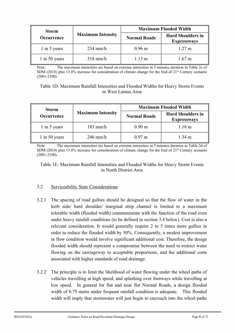
1 in 5 years 234 mm/h 0.96 m 1.27 m
1 in 50 years 318 mm/h 1.13 m 1.67 m
Note: The maximum intensities are based on extreme intensities in 5 minutes duration in Table 2c of SDM (2018) plus 13.8% increase for consideration of climate change for the End of 21st Century scenario (2081-2100).
Table 1D: Maximum Rainfall Intensities and Flooded Widths for Heavy Storm Events in West Lantau Area
Storm Occurrence
Maximum Intensity Maximum Flooded Width
Normal Roads Hard Shoulders in Expressways
1 in 5 years 183 mm/h 0.90 m 1.18 m
1 in 50 years 246 mm/h 0.97 m 1.34 m
Note: The maximum intensities are based on extreme intensities in 5 minutes duration in Table 2d of SDM (2018) plus 13.8% increase for consideration of climate change for the End of 21st Century scenario (2081-2100).
Table 1E: Maximum Rainfall Intensities and Flooded Widths for Heavy Storm Events in North District Area
3.2 Serviceability State Considerations 3.2.1 The spacing of road gullies should be designed so that the flow of water in the
kerb side/ hard shoulder/ marginal strip channel is limited to a maximum tolerable width (flooded width) commensurate with the function of the road even under heavy rainfall conditions (to be defined in section 3.4 below). Cost is also a relevant consideration. It would generally require 2 to 5 times more gullies in order to reduce the flooded width by 50%. Consequently, a modest improvement in flow condition would involve significant additional cost. Therefore, the design flooded width should represent a compromise between the need to restrict water flowing on the carriageway to acceptable proportions, and the additional costs associated with higher standards of road drainage.
3.2.2 The principle is to limit the likelihood of water flowing under the wheel paths of
vehicles travelling at high speed, and splashing over footways while travelling at low speed. In general for flat and near flat Normal Roads, a design flooded width of 0.75 metre under frequent rainfall condition is adequate. This flooded width will imply that stormwater will just begin to encroach into the wheel paths
RD/GN/035A Guidance Notes on Road Pavement Drainage Design Page 6 of 73
of vehicles, or would be restricted within the marginal strip, if provided.
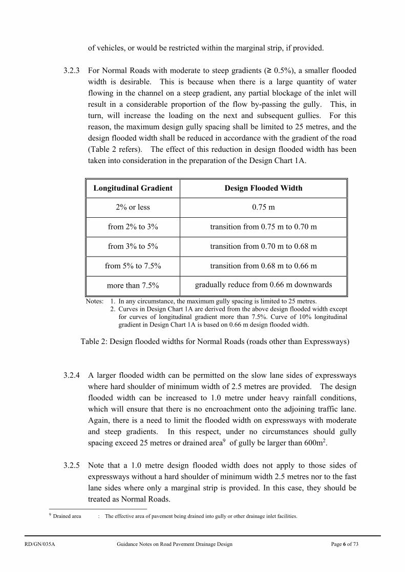
3.2.3 For Normal Roads with moderate to steep gradients (≥ 0.5%), a smaller flooded width is desirable. This is because when there is a large quantity of water flowing in the channel on a steep gradient, any partial blockage of the inlet will result in a considerable proportion of the flow by-passing the gully. This, in turn, will increase the loading on the next and subsequent gullies. For this reason, the maximum design gully spacing shall be limited to 25 metres, and the design flooded width shall be reduced in accordance with the gradient of the road (Table 2 refers). The effect of this reduction in design flooded width has been taken into consideration in the preparation of the Design Chart 1A.
Longitudinal Gradient Design Flooded Width
2% or less 0.75 m
from 2% to 3% transition from 0.75 m to 0.70 m
from 3% to 5% transition from 0.70 m to 0.68 m
from 5% to 7.5% transition from 0.68 m to 0.66 m
more than 7.5% gradually reduce from 0.66 m downwards
Notes: 1. In any circumstance, the maximum gully spacing is limited to 25 metres. 2. Curves in Design Chart 1A are derived from the above design flooded width except
for curves of longitudinal gradient more than 7.5%. Curve of 10% longitudinal gradient in Design Chart 1A is based on 0.66 m design flooded width.
Table 2: Design flooded widths for Normal Roads (roads other than Expressways)
3.2.4 A larger flooded width can be permitted on the slow lane sides of expressways where hard shoulder of minimum width of 2.5 metres are provided. The design flooded width can be increased to 1.0 metre under heavy rainfall conditions, which will ensure that there is no encroachment onto the adjoining traffic lane. Again, there is a need to limit the flooded width on expressways with moderate and steep gradients. In this respect, under no circumstances should gully spacing exceed 25 metres or drained area9 of gully be larger than 600m2.
3.2.5 Note that a 1.0 metre design flooded width does not apply to those sides of
expressways without a hard shoulder of minimum width 2.5 metres nor to the fast lane sides where only a marginal strip is provided. In this case, they should be treated as Normal Roads.
9 Drained area : The effective area of pavement being drained into gully or other drainage inlet facilities.
RD/GN/035A Guidance Notes on Road Pavement Drainage Design Page 7 of 73
3.3 Climatic Considerations 3.3.1 To represent a compromise between the need to restrict water flowing on the
carriageway to acceptable proportions, and the additional costs associated with higher standards of road drainage, the designer should equate heavy rainfall condition for serviceability state design to be the intensity of a rainstorm (5 minutes or more in duration) having a probability of occurrence of not more than 2 times per year. According to the rainfall data from the Hong Kong Observatory plus 13.8% increase for consideration of climate change for the End of 21st Century scenario (2081-2100), this corresponds to an intensity of 147 mm/hour. It should be noted that a rainfall intensity of 147 mm/hour or more would be such that most motorists would consider it prudent to slow down owing to lack of visibility.
3.4 Ultimate State Considerations 3.4.1 Under the kerb and gully arrangement when a fixed number of gullies have been
constructed, the flow width and flow height will increase with the rainfall intensity. If the flow height is too great, the kerb may be overtopped and in certain situation, the surface water may cause flooding to adjoining land or properties. This should be avoided even in exceptionally heavy rainstorms.
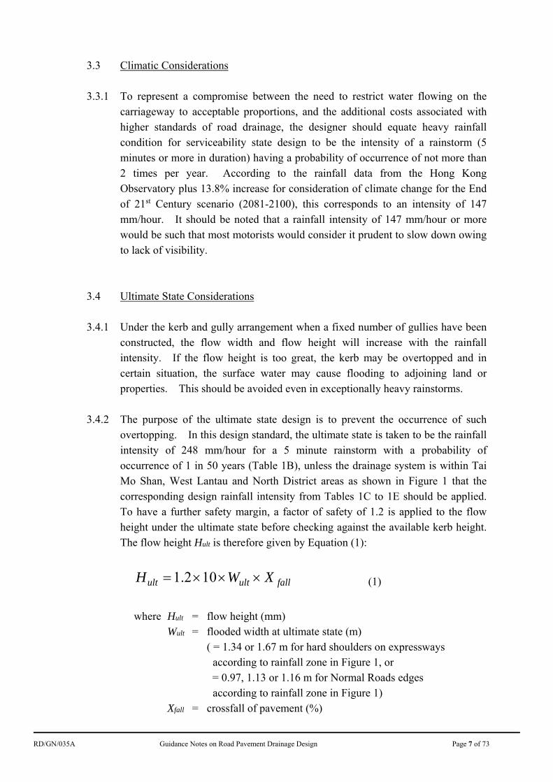
3.4.2 The purpose of the ultimate state design is to prevent the occurrence of such
overtopping. In this design standard, the ultimate state is taken to be the rainfall intensity of 248 mm/hour for a 5 minute rainstorm with a probability of occurrence of 1 in 50 years (Table 1B), unless the drainage system is within Tai Mo Shan, West Lantau and North District areas as shown in Figure 1 that the corresponding design rainfall intensity from Tables 1C to 1E should be applied. To have a further safety margin, a factor of safety of 1.2 is applied to the flow height under the ultimate state before checking against the available kerb height. The flow height Hult is therefore given by Equation (1):
fallultult XWH 102.1 (1)
where Hult = flow height (mm)
Wult = flooded width at ultimate state (m) ( = 1.34 or 1.67 m for hard shoulders on expressways
according to rainfall zone in Figure 1, or = 0.97, 1.13 or 1.16 m for Normal Roads edges according to rainfall zone in Figure 1)
Xfall = crossfall of pavement (%)
RD/GN/035A Guidance Notes on Road Pavement Drainage Design Page 8 of 73
3.4.3 This requirement can be satisfied in most cases. In general, the flow height will
exceed the standard kerb height of 125 mm only if the crossfall is more than 7.8% for hard shoulder flow on expressways or 10.7% on Normal Roads. If the flow height exceeds the kerb height, the drainage design should be revised. The flooded width adopted in computation of the flow height should follow the values in Tables 1B to 1E. For example, if the road drainage system is located in Tai Mo Shan area, flooded width at ultimate state of 1.67 and 1.16 m should be used and the maximum allowable crossfall will be 6.2% for hard shoulder flow on expressways and 9.0% on Normal Roads respectively.
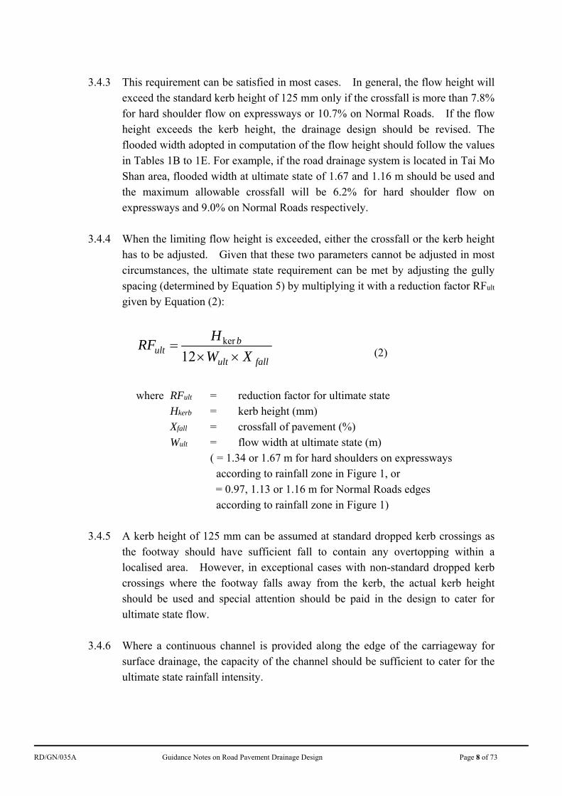
3.4.4 When the limiting flow height is exceeded, either the crossfall or the kerb height
has to be adjusted. Given that these two parameters cannot be adjusted in most circumstances, the ultimate state requirement can be met by adjusting the gully spacing (determined by Equation 5) by multiplying it with a reduction factor RFult given by Equation (2):
fallult
bult XW
HRF
12ker
(2)
where RFult = reduction factor for ultimate state
Hkerb = kerb height (mm) Xfall = crossfall of pavement (%) Wult = flow width at ultimate state (m)
( = 1.34 or 1.67 m for hard shoulders on expressways according to rainfall zone in Figure 1, or
= 0.97, 1.13 or 1.16 m for Normal Roads edges according to rainfall zone in Figure 1)
3.4.5 A kerb height of 125 mm can be assumed at standard dropped kerb crossings as
the footway should have sufficient fall to contain any overtopping within a localised area. However, in exceptional cases with non-standard dropped kerb crossings where the footway falls away from the kerb, the actual kerb height should be used and special attention should be paid in the design to cater for ultimate state flow.
3.4.6 Where a continuous channel is provided along the edge of the carriageway for
surface drainage, the capacity of the channel should be sufficient to cater for the ultimate state rainfall intensity.
RD/GN/035A Guidance Notes on Road Pavement Drainage Design Page 9 of 73
3.5 Crossfall 3.5.1 Crossfall should be provided on all roads to drain stormwater to the kerb side
channels. On straight lengths of roads, crossfall is usually provided in the form of camber. On curves, crossfall is usually provided through superelevation.
3.5.2 A slight variation in crossfall will result in a significant effect in gully spacing in
particular on flat sections. As illustrated in Figure 2 (section 3.7.2), an increase in crossfall from 2.5% to 3.0% can increase gully spacing by about 25%. Therefore a suitable crossfall should be adopted to avoid having gullies at unnecessarily close spacings. On roads with moderate or steep gradients
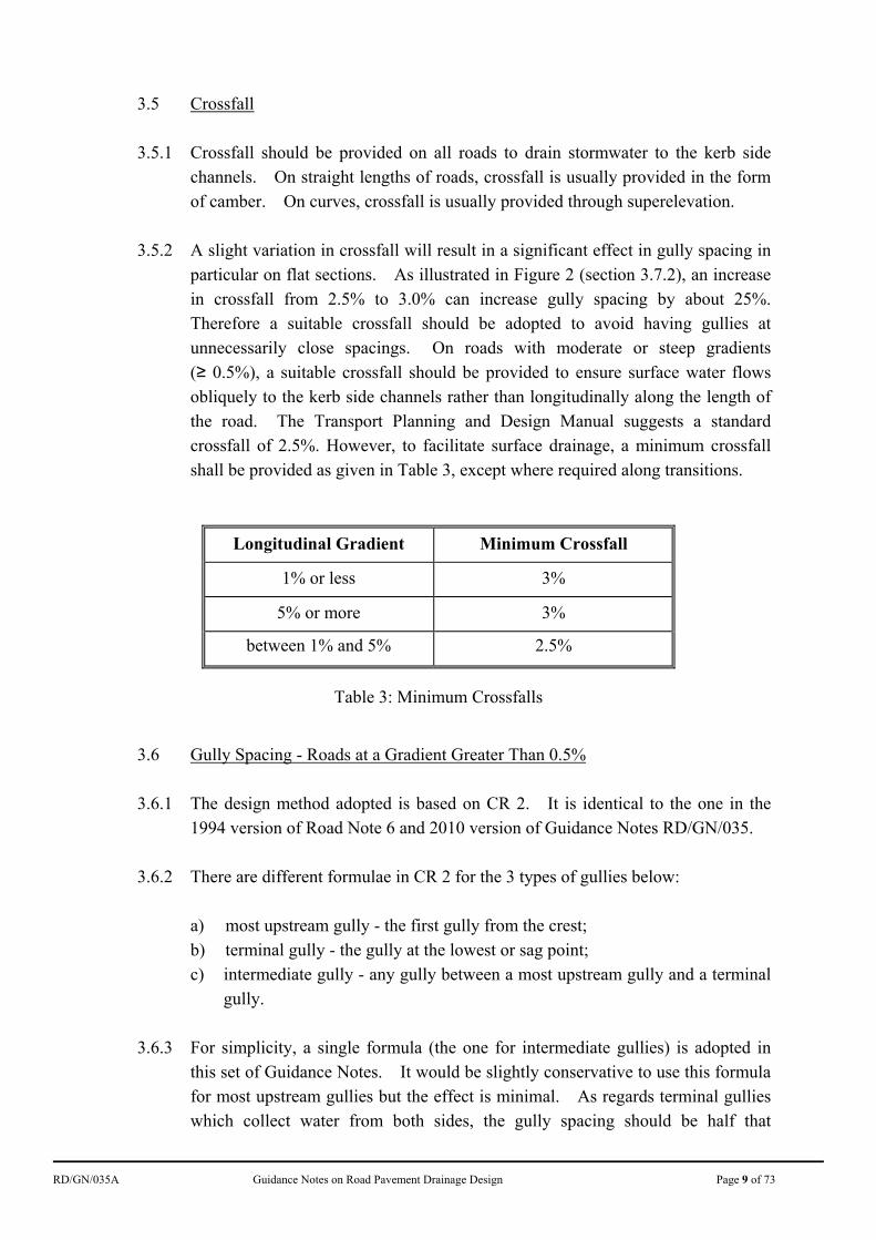
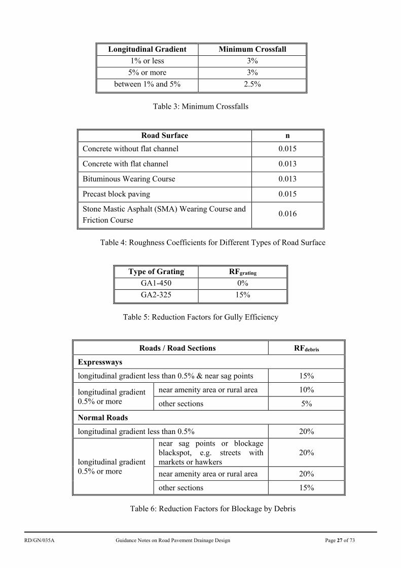
(≥ 0.5%), a suitable crossfall should be provided to ensure surface water flows obliquely to the kerb side channels rather than longitudinally along the length of the road. The Transport Planning and Design Manual suggests a standard crossfall of 2.5%. However, to facilitate surface drainage, a minimum crossfall shall be provided as given in Table 3, except where required along transitions.
Longitudinal Gradient Minimum Crossfall
1% or less 3%
5% or more 3%
between 1% and 5% 2.5%
Table 3: Minimum Crossfalls
3.6 Gully Spacing - Roads at a Gradient Greater Than 0.5% 3.6.1 The design method adopted is based on CR 2. It is identical to the one in the
1994 version of Road Note 6 and 2010 version of Guidance Notes RD/GN/035. 3.6.2 There are different formulae in CR 2 for the 3 types of gullies below:
a) most upstream gully - the first gully from the crest; b) terminal gully - the gully at the lowest or sag point; c) intermediate gully - any gully between a most upstream gully and a terminal
gully.
3.6.3 For simplicity, a single formula (the one for intermediate gullies) is adopted in this set of Guidance Notes. It would be slightly conservative to use this formula for most upstream gullies but the effect is minimal. As regards terminal gullies which collect water from both sides, the gully spacing should be half that
RD/GN/035A Guidance Notes on Road Pavement Drainage Design Page 10 of 73
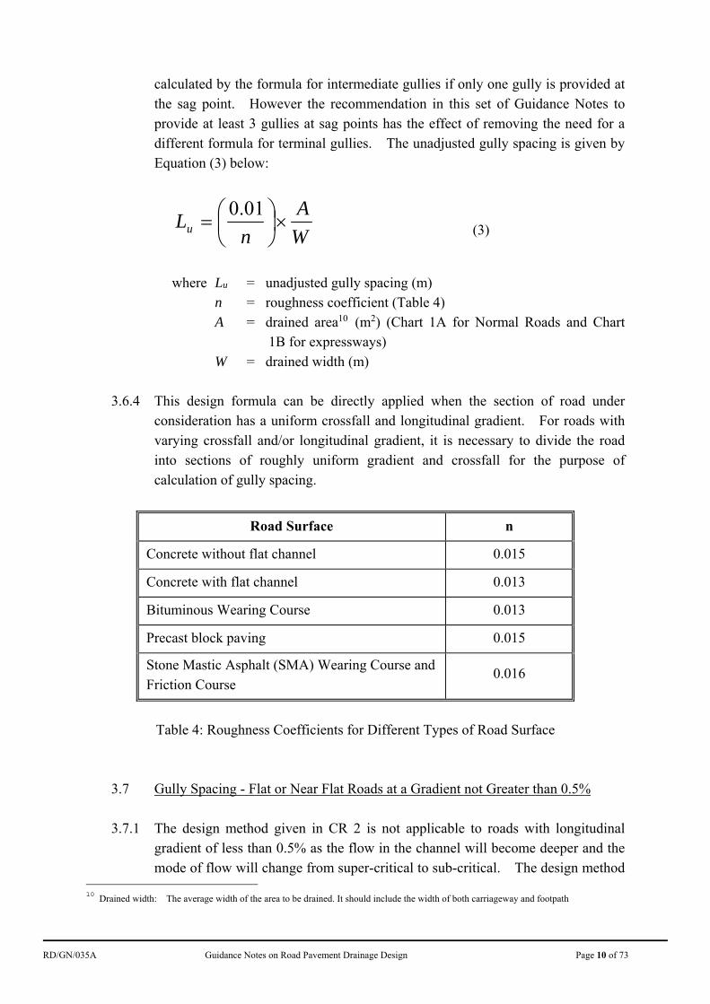
calculated by the formula for intermediate gullies if only one gully is provided at the sag point. However the recommendation in this set of Guidance Notes to provide at least 3 gullies at sag points has the effect of removing the need for a different formula for terminal gullies. The unadjusted gully spacing is given by Equation (3) below:
W
A
nLu
01.0 (3)
where Lu = unadjusted gully spacing (m)
n = roughness coefficient (Table 4) A = drained area10 (m2) (Chart 1A for Normal Roads and Chart
1B for expressways) W = drained width (m)
3.6.4 This design formula can be directly applied when the section of road under
consideration has a uniform crossfall and longitudinal gradient. For roads with varying crossfall and/or longitudinal gradient, it is necessary to divide the road into sections of roughly uniform gradient and crossfall for the purpose of calculation of gully spacing.
Road Surface n
Concrete without flat channel 0.015
Concrete with flat channel 0.013
Bituminous Wearing Course 0.013
Precast block paving 0.015
Stone Mastic Asphalt (SMA) Wearing Course and Friction Course
0.016
Table 4: Roughness Coefficients for Different Types of Road Surface
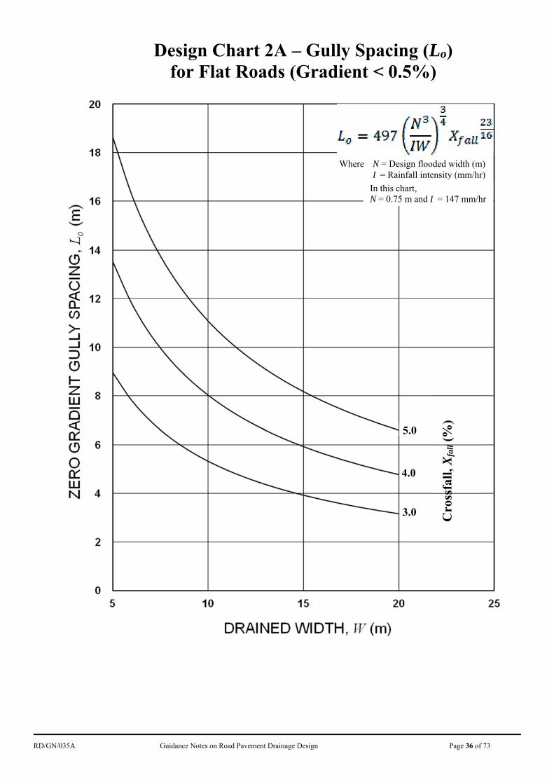
3.7 Gully Spacing - Flat or Near Flat Roads at a Gradient not Greater than 0.5% 3.7.1 The design method given in CR 2 is not applicable to roads with longitudinal
gradient of less than 0.5% as the flow in the channel will become deeper and the mode of flow will change from super-critical to sub-critical. The design method
10
Drained width: The average width of the area to be drained. It should include the width of both carriageway and footpath
RD/GN/035A Guidance Notes on Road Pavement Drainage Design Page 11 of 73
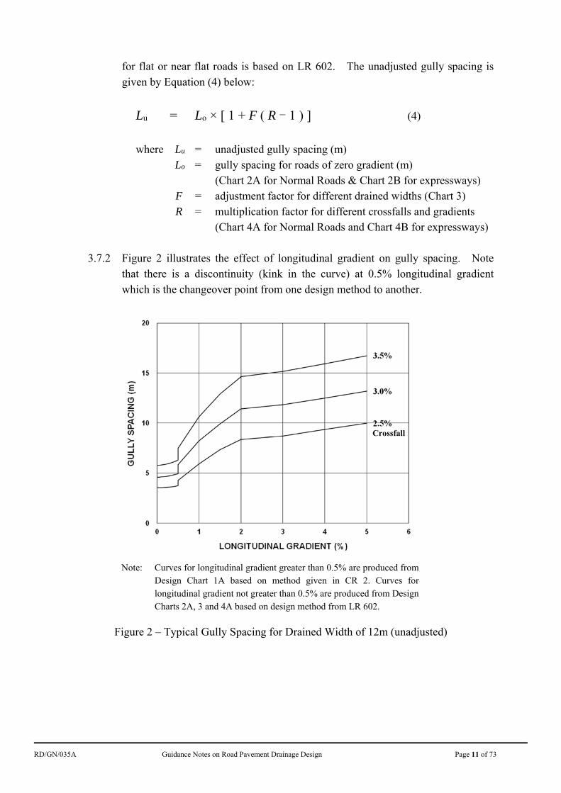
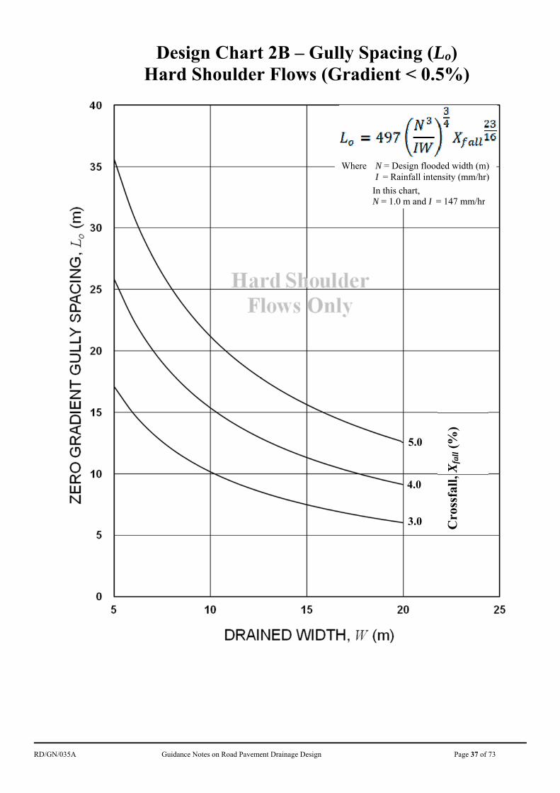
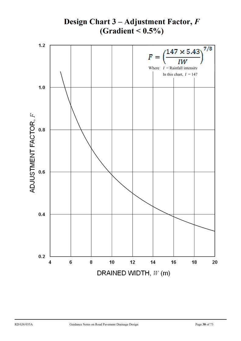
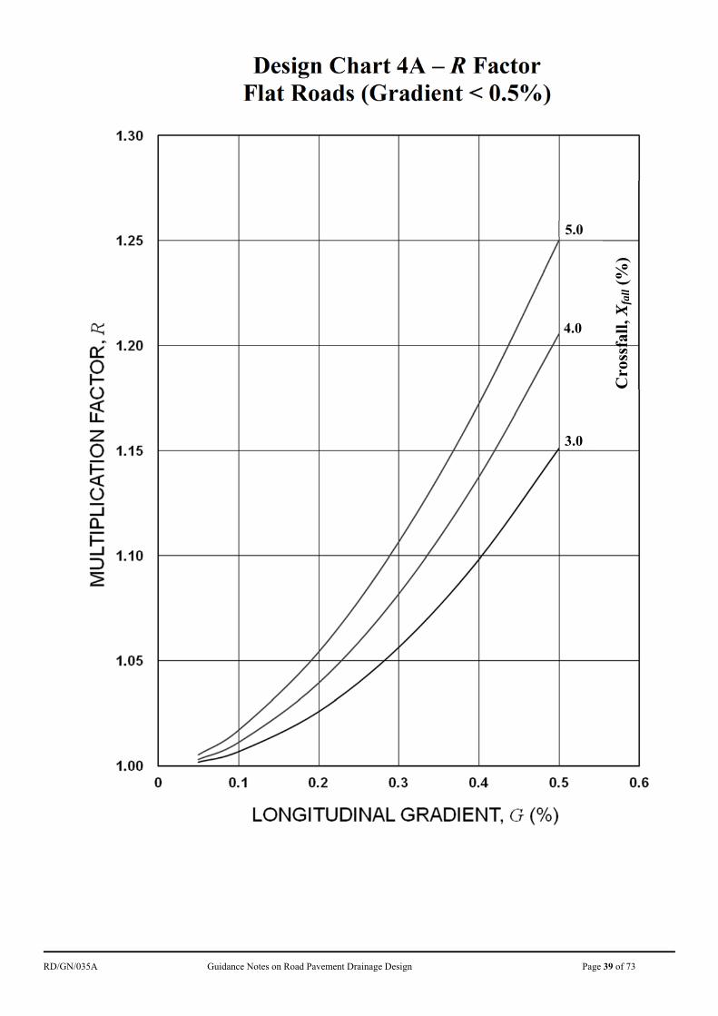
for flat or near flat roads is based on LR 602. The unadjusted gully spacing is given by Equation (4) below:
Lu = Lo × [ 1 + F ( R - 1 ) ] (4)
where Lu = unadjusted gully spacing (m) Lo = gully spacing for roads of zero gradient (m)
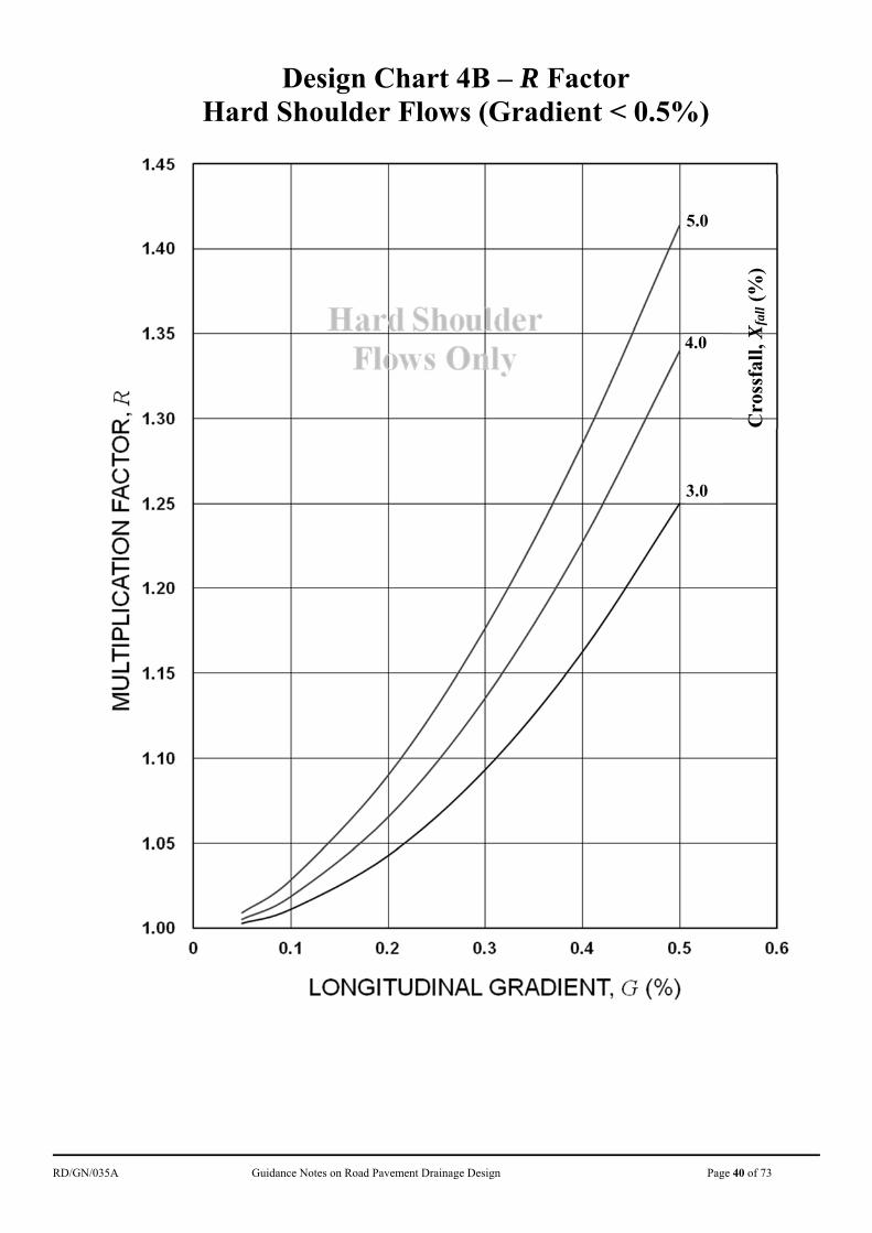
(Chart 2A for Normal Roads & Chart 2B for expressways) F = adjustment factor for different drained widths (Chart 3) R = multiplication factor for different crossfalls and gradients
(Chart 4A for Normal Roads and Chart 4B for expressways) 3.7.2 Figure 2 illustrates the effect of longitudinal gradient on gully spacing. Note
that there is a discontinuity (kink in the curve) at 0.5% longitudinal gradient which is the changeover point from one design method to another.
Note: Curves for longitudinal gradient greater than 0.5% are produced from
Design Chart 1A based on method given in CR 2. Curves for longitudinal gradient not greater than 0.5% are produced from Design Charts 2A, 3 and 4A based on design method from LR 602.
Figure 2 – Typical Gully Spacing for Drained Width of 12m (unadjusted)
Crossfall
RD/GN/035A Guidance Notes on Road Pavement Drainage Design Page 12 of 73
3.8 Design Gully Spacing and Reduction Factors 3.8.1 The design gully spacing is derived by applying reduction factors to the
unadjusted gully spacing determined as described above. There are two reduction factors, one for gully efficiency and the other for blockage by debris:
L = Lu × (1 - RFgrating) × ( 1 - RFdebris) (5)
where L = design gully spacing (m) Lu = unadjusted gully spacing (m) RFgrating = reduction factor for gully efficiency (Table 5) RFdebris = reduction factor for blockage by debris (Table 6)
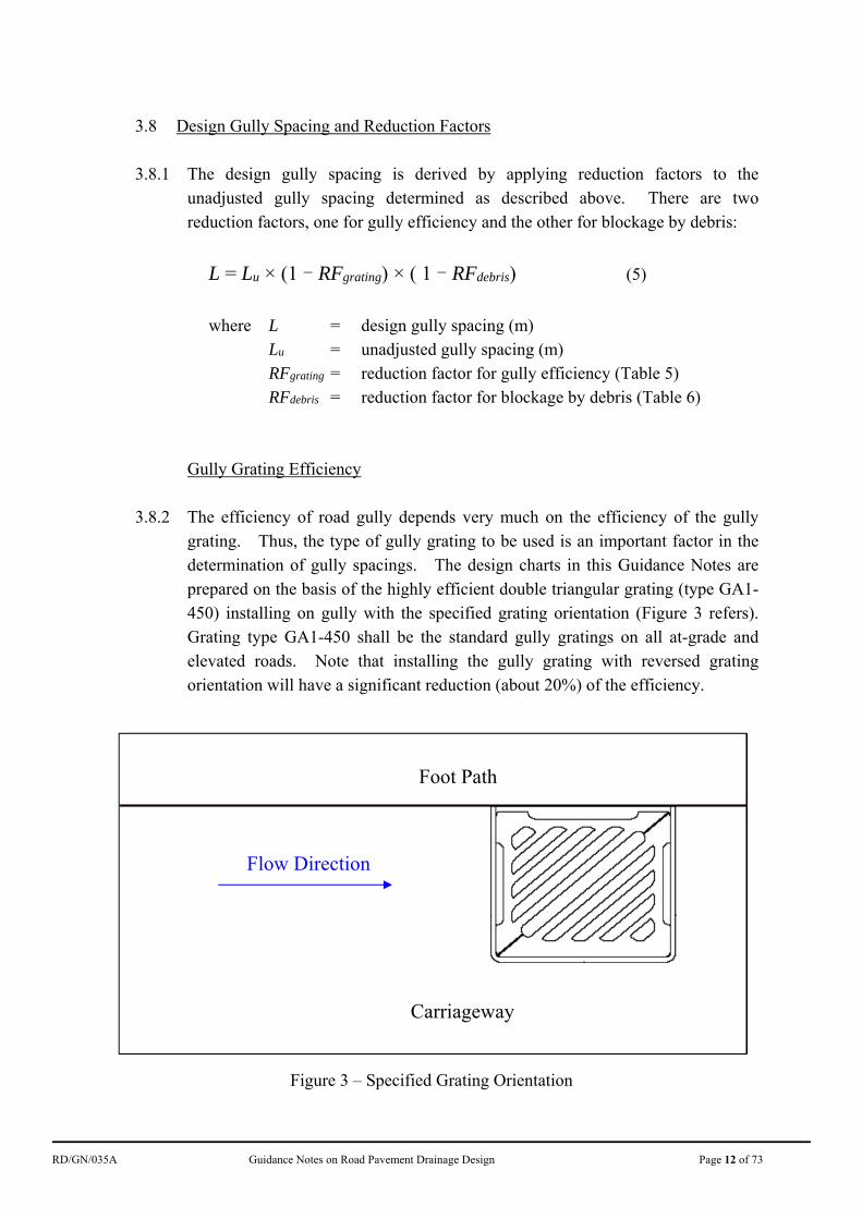
Gully Grating Efficiency 3.8.2 The efficiency of road gully depends very much on the efficiency of the gully
grating. Thus, the type of gully grating to be used is an important factor in the determination of gully spacings. The design charts in this Guidance Notes are prepared on the basis of the highly efficient double triangular grating (type GA1-450) installing on gully with the specified grating orientation (Figure 3 refers). Grating type GA1-450 shall be the standard gully gratings on all at-grade and elevated roads. Note that installing the gully grating with reversed grating orientation will have a significant reduction (about 20%) of the efficiency.
Figure 3 – Specified Grating Orientation
Flow Direction
Foot Path
Carriageway
RD/GN/035A Guidance Notes on Road Pavement Drainage Design Page 13 of 73
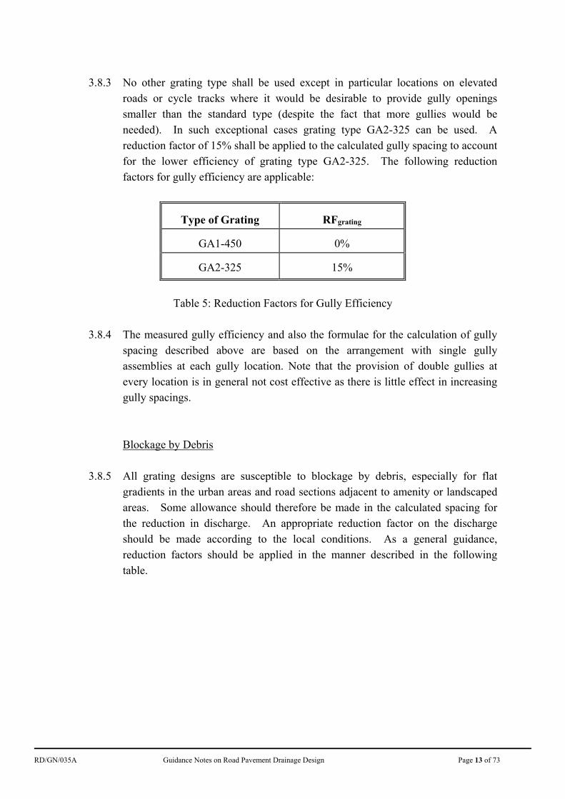
3.8.3 No other grating type shall be used except in particular locations on elevated
roads or cycle tracks where it would be desirable to provide gully openings smaller than the standard type (despite the fact that more gullies would be needed). In such exceptional cases grating type GA2-325 can be used. A reduction factor of 15% shall be applied to the calculated gully spacing to account for the lower efficiency of grating type GA2-325. The following reduction factors for gully efficiency are applicable:
Type of Grating RFgrating
GA1-450 0%
GA2-325 15%
Table 5: Reduction Factors for Gully Efficiency
3.8.4 The measured gully efficiency and also the formulae for the calculation of gully
spacing described above are based on the arrangement with single gully assemblies at each gully location. Note that the provision of double gullies at every location is in general not cost effective as there is little effect in increasing gully spacings.
Blockage by Debris 3.8.5 All grating designs are susceptible to blockage by debris, especially for flat
gradients in the urban areas and road sections adjacent to amenity or landscaped areas. Some allowance should therefore be made in the calculated spacing for the reduction in discharge. An appropriate reduction factor on the discharge should be made according to the local conditions. As a general guidance, reduction factors should be applied in the manner described in the following table.
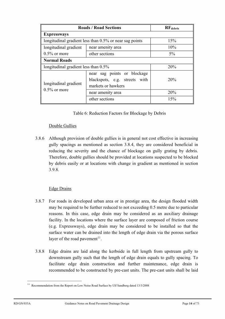
RD/GN/035A Guidance Notes on Road Pavement Drainage Design Page 14 of 73
Roads / Road Sections RFdebris
Expressways
longitudinal gradient less than 0.5% or near sag points 15%
longitudinal gradient 0.5% or more
near amenity area 10%
other sections 5%
Normal Roads
longitudinal gradient less than 0.5% 20%
longitudinal gradient 0.5% or more
near sag points or blockage blackspots, e.g. streets with markets or hawkers
20%
near amenity area 20%
other sections 15%
Table 6: Reduction Factors for Blockage by Debris
Double Gullies
3.8.6 Although provision of double gullies is in general not cost effective in increasing
gully spacings as mentioned as section 3.8.4, they are considered beneficial in reducing the severity and the chance of blockage on gully grating by debris. Therefore, double gullies should be provided at locations suspected to be blocked by debris easily or at locations with change in gradient as mentioned in section 3.9.8.
Edge Drains 3.8.7 For roads in developed urban area or in prestige area, the design flooded width
may be required to be further reduced to not exceeding 0.5 metre due to particular reasons. In this case, edge drain may be considered as an auxiliary drainage facility. In the locations where the surface layer are composed of friction course (e.g. Expressways), edge drain may be considered to be installed so that the surface water can be drained into the length of edge drain via the porous surface layer of the road pavement11.
3.8.8 Edge drains are laid along the kerbside in full length from upstream gully to
downstream gully such that the length of edge drain equals to gully spacing. To facilitate edge drain construction and further maintenance, edge drain is recommended to be constructed by pre-cast units. The pre-cast units shall be laid
11
Recommendation from the Report on Low Noise Road Surface by Ulf Sandberg dated 13/3/2008
RD/GN/035A Guidance Notes on Road Pavement Drainage Design Page 15 of 73
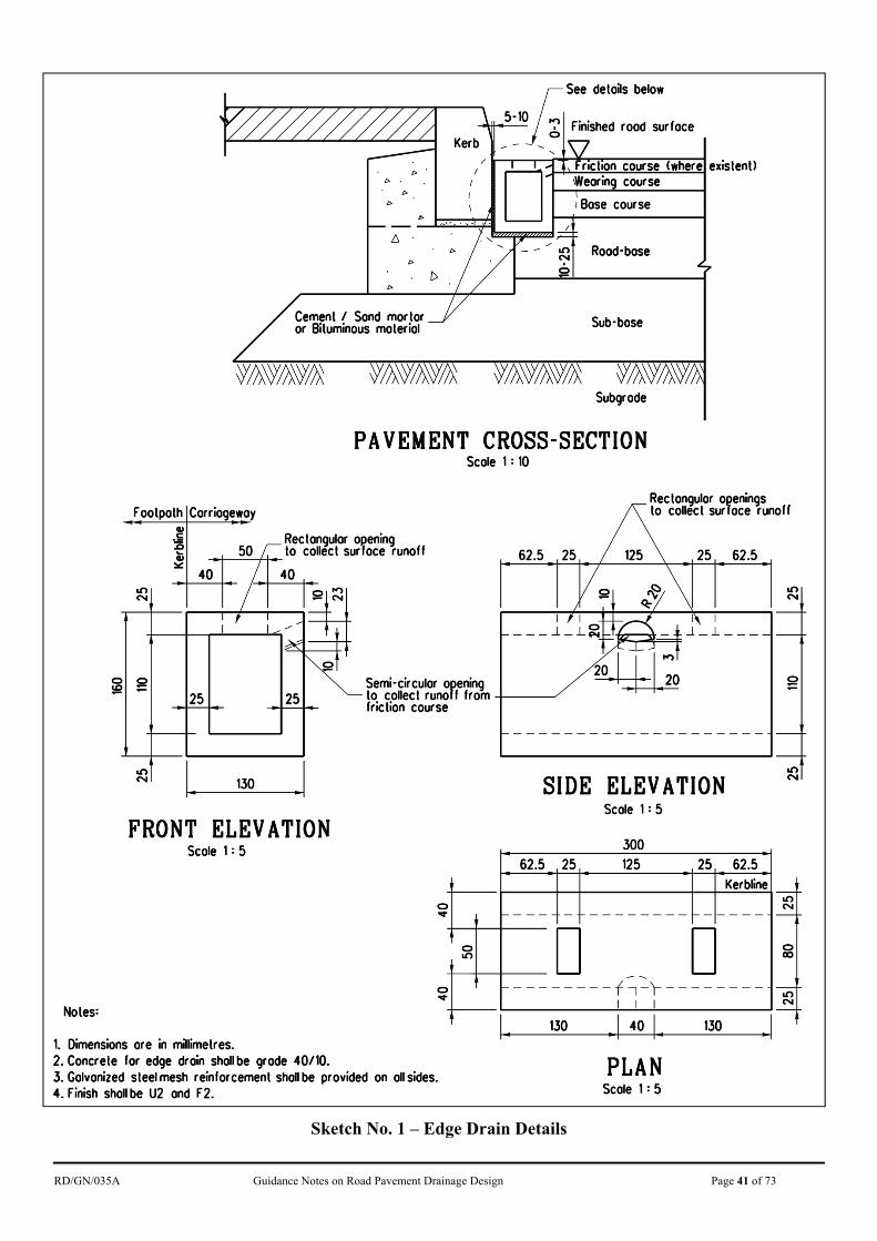
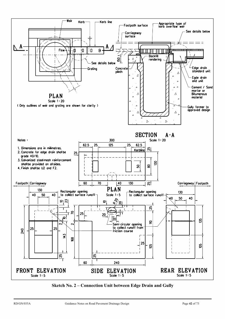
along the kerbs and follow the road gradient. Details of edge drain in pre-cast unit are shown in Sketch Nos. 1 and 2.
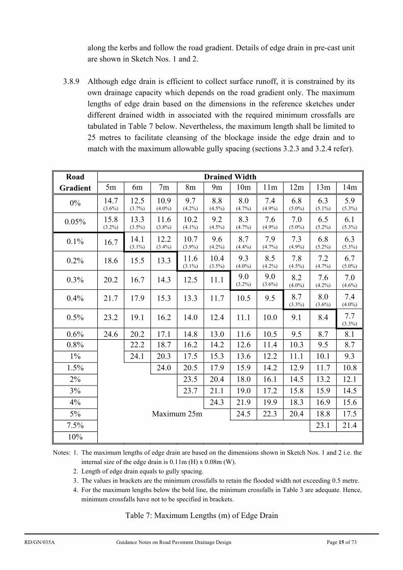
3.8.9 Although edge drain is efficient to collect surface runoff, it is constrained by its
own drainage capacity which depends on the road gradient only. The maximum lengths of edge drain based on the dimensions in the reference sketches under different drained width in associated with the required minimum crossfalls are tabulated in Table 7 below. Nevertheless, the maximum length shall be limited to 25 metres to facilitate cleansing of the blockage inside the edge drain and to match with the maximum allowable gully spacing (sections 3.2.3 and 3.2.4 refer).
Road Gradient
Drained Width 5m 6m 7m 8m 9m 10m 11m 12m 13m 14m
0% 14.7 (3.6%)
12.5 (3.7%)
10.9(4.0%)
9.7 (4.2%)
8.8 (4.5%)
8.0 (4.7%)
7.4 (4.9%)
6.8 (5.0%)
6.3 (5.1%)
5.9 (5.3%)
0.05% 15.8 (3.2%)
13.3 (3.5%)
11.6(3.8%)
10.2(4.1%)
9.2 (4.5%)
8.3 (4.7%)
7.6 (4.9%)
7.0 (5.0%)
6.5 (5.2%)
6.1 (5.3%)
0.1% 16.7 14.1 (3.1%)
12.2(3.4%)
10.7(3.9%)
9.6 (4.2%)
8.7 (4.4%)
7.9 (4.7%)
7.3 (4.9%)
6.8 (5.2%)
6.3 (5.3%)
0.2% 18.6 15.5 13.3 11.6(3.1%)
10.4(3.5%)
9.3 (4.0%)
8.5 (4.2%)
7.8 (4.5%)
7.2 (4.7%)
6.7 (5.0%)
0.3% 20.2 16.7 14.3 12.5 11.1 9.0 (3.2%)
9.0 (3.6%)
8.2 (4.0%)
7.6 (4.2%)
7.0 (4.6%)
0.4% 21.7 17.9 15.3 13.3 11.7 10.5 9.5 8.7 (3.3%)
8.0 (3.6%)
7.4 (4.0%)
0.5% 23.2 19.1 16.2 14.0 12.4 11.1 10.0 9.1 8.4 7.7 (3.3%)
0.6% 24.6 20.2 17.1 14.8 13.0 11.6 10.5 9.5 8.7 8.1 0.8% 22.2 18.7 16.2 14.2 12.6 11.4 10.3 9.5 8.7
1% 24.1 20.3 17.5 15.3 13.6 12.2 11.1 10.1 9.3
1.5% 24.0 20.5 17.9 15.9 14.2 12.9 11.7 10.8
2% 23.5 20.4 18.0 16.1 14.5 13.2 12.1
3% 23.7 21.1 19.0 17.2 15.8 15.9 14.5
4% 24.3 21.9 19.9 18.3 16.9 15.6
5% Maximum 25m 24.5 22.3 20.4 18.8 17.5
7.5% 23.1 21.4
10%
Notes: 1. The maximum lengths of edge drain are based on the dimensions shown in Sketch Nos. 1 and 2 i.e. the internal size of the edge drain is 0.11m (H) x 0.08m (W).
2. Length of edge drain equals to gully spacing. 3. The values in brackets are the minimum crossfalls to retain the flooded width not exceeding 0.5 metre. 4. For the maximum lengths below the bold line, the minimum crossfalls in Table 3 are adequate. Hence,
minimum crossfalls have not to be specified in brackets.
Table 7: Maximum Lengths (m) of Edge Drain
RD/GN/035A Guidance Notes on Road Pavement Drainage Design Page 16 of 73
3.8.10 When edge drain is provided as auxiliary drainage facility, gully spacing has to
be adjusted accordingly. The higher value between the design gully spacing in equation (5) and the maximum length of edge drain in Table 7 shall be adopted as the gully spacing.
3.8.11 Edge drain is not recommended to be provided near landscaped and amenity
areas as it is easily subjected to blockage by fallen leaves. Adequate maintenance e.g. cleansing by pressure jet has to be carried out to ensure its proper functioning.
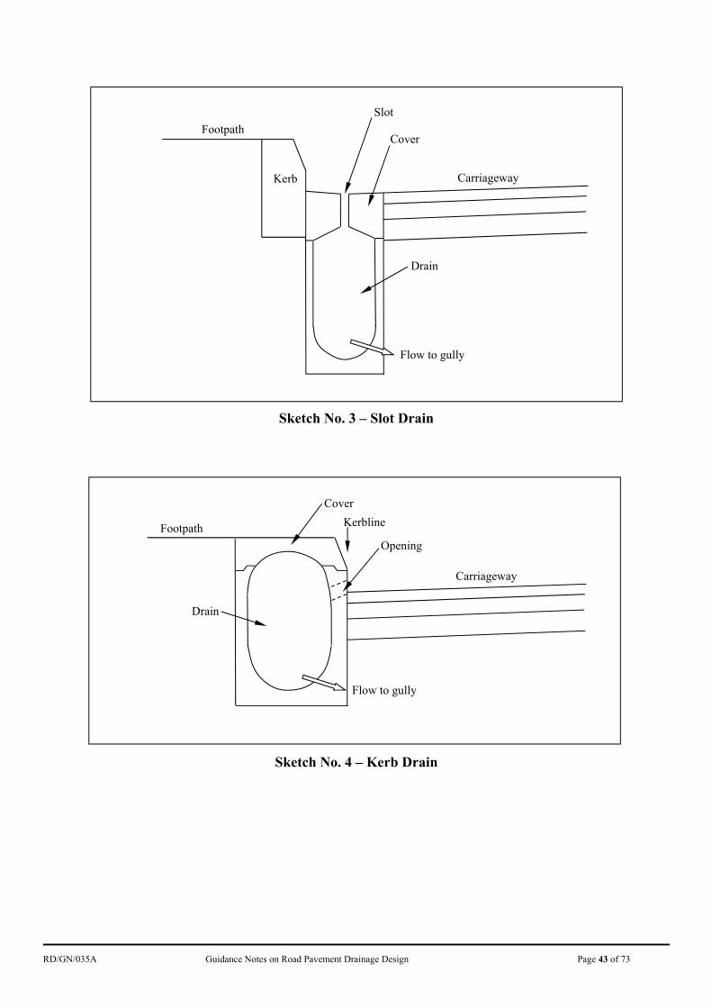
3.8.12 Besides edge drain, other auxiliary drainage facilities such as slot drain (Sketch
No. 3), kerb drain (Sketch No. 4) and other proprietary products can also be applied in road drainage design as long as sufficient documents are provided to prove the effectiveness of the design.
3.9 Details to Facilitate Entry of Surface Water
Kerb Overflow Weirs 3.9.1 Kerb overflow weirs serve two functions. Firstly the vertical opening is a kind
of kerb inlet and would provide additional drainage path under normal
circumstances. This is useful in roads with moderate or steep gradient (≥ 0.5%) where the higher flow velocity enables a certain amount of surface water to by-pass the gully through the very narrow inner edge of gully assemblies. The provision of overflow weirs on roads with moderate and steep gradient is recommended as they remove the inner edges and also provide additional inlet openings.
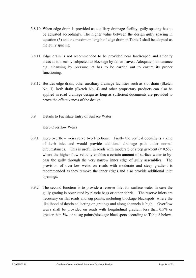
3.9.2 The second function is to provide a reserve inlet for surface water in case the
gully grating is obstructed by plastic bags or other debris. The reserve inlets are necessary on flat roads and sag points, including blockage blackspots, where the likelihood of debris collecting on gratings and along channels is high. Overflow weirs shall be provided on roads with longitudinal gradient less than 0.5% or greater than 5%, or at sag points/blockage blackspots according to Table 8 below.
RD/GN/035A Guidance Notes on Road Pavement Drainage Design Page 17 of 73
Section of Road Minimum Rate of Provision of
Overflow weirs
longitudinal gradient > 7% Every other gully
longitudinal gradient > 5% but not more than 7%
Every third gully
longitudinal gradient between 0.5% and 5% inclusive
No overflow weir
longitudinal gradient < 0.5% Every third gully
Sag points or blockage blackspots.
Every gully
Table 8: Minimum Rate of Provision of Overflow Weirs
3.9.3 The drawback of overflow weirs is that they provide yet another passageway for
debris to enter the gully pot which may eventually cause blockage of the gully. It is therefore important to provide bars across the vertical opening to reduce the size of the openings and to prevent the entry of large particles. Where provided on roads with moderate or steep gradient, the bars should be horizontal or parallel to the length of the weir so as to maintain drainage efficiency. Where provided on flat roads or sag points, the bars should be vertical as this arrangement is more effective in preventing entry of debris.
Gullies at Sag Points (Minimum of 4 Gullies) 3.9.4 Sag points could be the trough at the bottom of a hill or locally at bends created
by superelevation. Any surface water not collected by the intermediate gullies will end up at the sag points. It is therefore important to provide spare gully capacity at sag points. A minimum of 4 gullies should be provided on all sag points. The first one collects surface water from one side of the trough, the last one collects surface water from the other side, and the middle two gullies provides spare capacity. As mentioned in section 3.9.2, overflow weir should be provided for each gully.
3.9.5 The catchment area is the road area such that rain falling onto which may end up
at the sag point. For hilly terrain the catchment area of a sag point could be very large. Note that surface water always follows the line of greatest slope rather than confined to one side of the carriageway. Hence when there are gullies at both sides of a road at a sag point, very often the two sets of gullies have catchment areas quite different in sizes unless the catchment area is a straight
RD/GN/035A Guidance Notes on Road Pavement Drainage Design Page 18 of 73
road with camber throughout. 3.9.6 If the catchment area concerned becomes larger, there is a higher chance for a
certain amount of surface run-off bypassing any blocked intermediate gullies and eventually reaching the sag point. In such circumstances, surface water may accumulate at the sag point and cause flooding and hazard to traffic. In view of the serious consequence, it is necessary to provide additional gullies at sag points to reduce the likelihood of such occurrence. It should be borne in mind, however, that the key for the proper functioning of the surface drainage system is the proper maintenance and clearance of blocked gullies rather than the addition of gullies. The number of additional gullies to be provided at sag points is affected by:
a) the likelihood of intermediate gullies being blocked on the surface or
internally; b) the size and layout of the catchment area; c) the relative importance of the road and the consequence of flooding; and d) the presence of alternative outlets (perhaps at a slightly higher level).
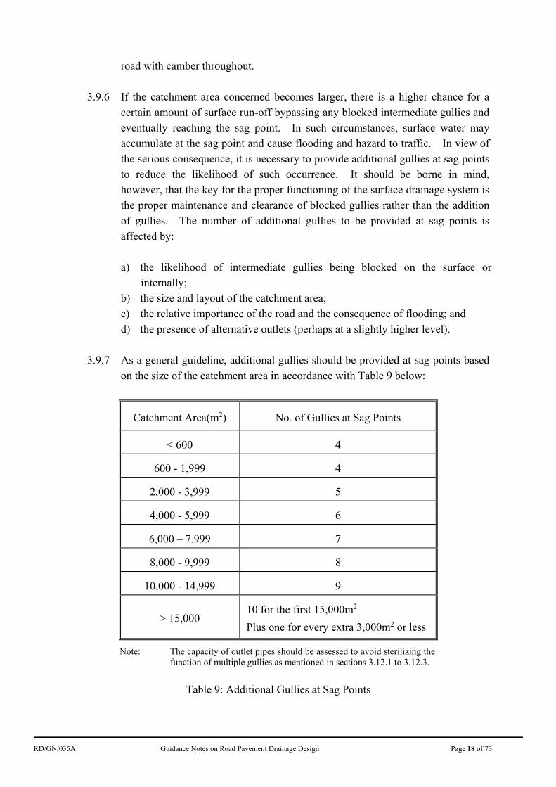
3.9.7 As a general guideline, additional gullies should be provided at sag points based
on the size of the catchment area in accordance with Table 9 below:
Catchment Area(m2) No. of Gullies at Sag Points
< 600 4
600 - 1,999 4
2,000 - 3,999 5
4,000 - 5,999 6
6,000 – 7,999 7
8,000 - 9,999 8
10,000 - 14,999 9
> 15,000
10 for the first 15,000m2
Plus one for every extra 3,000m2 or less
Note: The capacity of outlet pipes should be assessed to avoid sterilizing the function of multiple gullies as mentioned in sections 3.12.1 to 3.12.3.
Table 9: Additional Gullies at Sag Points
RD/GN/035A Guidance Notes on Road Pavement Drainage Design Page 19 of 73
Gullies Immediately Downstream of Moderate or Steep Gradients
3.9.8 On roads with moderate or steep gradient (≥ 0.5%), surface water follows the line of greatest slope and flows obliquely towards the kerb side channel. There is no significant effect on the size of the drained area if it is a constant gradient or a gradual transition. However, if the road suddenly flattens out, the surface water bypassing the last gully on the steep section may overload the first few gullies on the flatter section due to the oblique flow.
3.9.9 Provision should be made to intercept such oblique flow when a road with
moderate or steep gradient flattens out. As a general guide, the first 3 sets of gullies immediately downstream of a road section of longitudinal gradient 5% or more should be double gullies rather than single gullies. Also, adjacent gullies should be located at least one kerb length apart so that the portion of pavement between them can be properly constructed.
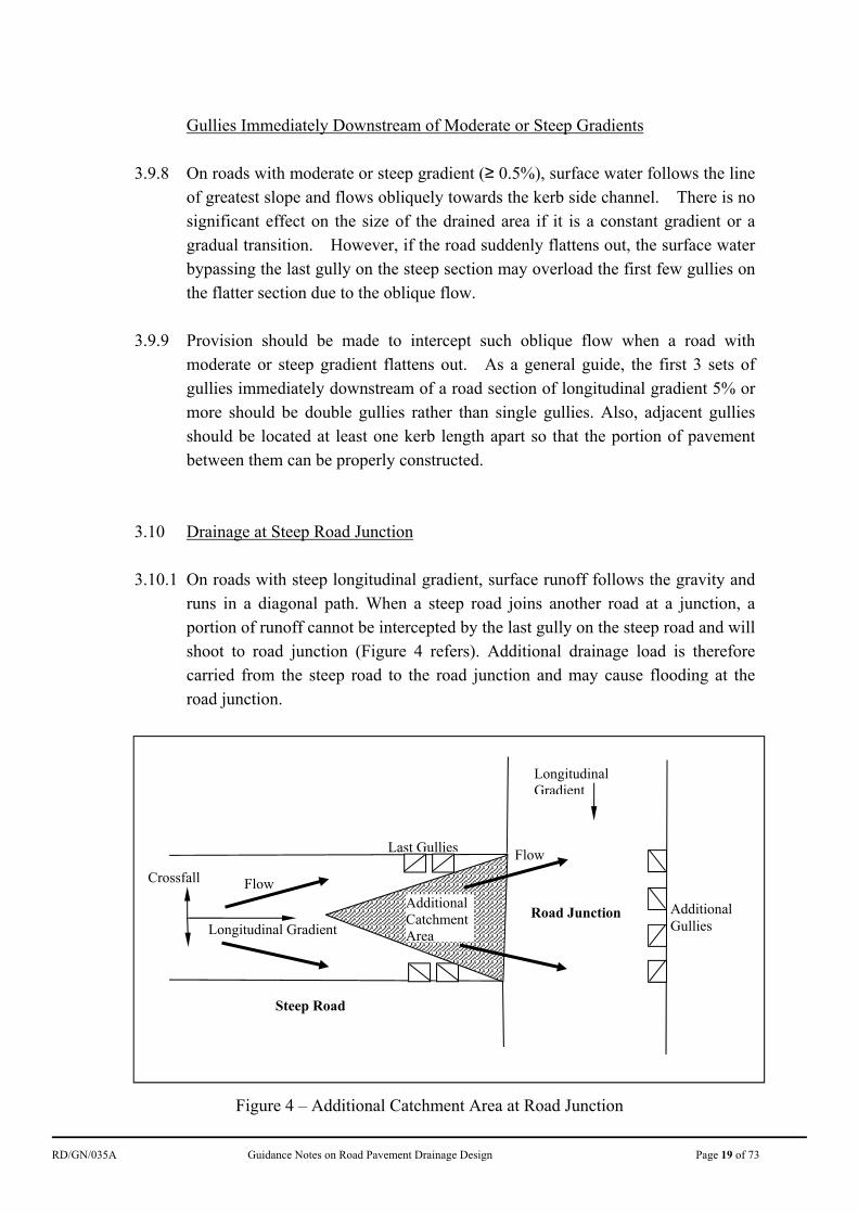
3.10 Drainage at Steep Road Junction 3.10.1 On roads with steep longitudinal gradient, surface runoff follows the gravity and
runs in a diagonal path. When a steep road joins another road at a junction, a portion of runoff cannot be intercepted by the last gully on the steep road and will shoot to road junction (Figure 4 refers). Additional drainage load is therefore carried from the steep road to the road junction and may cause flooding at the road junction.
Figure 4 – Additional Catchment Area at Road Junction
Additional Catchment Area
Crossfall
Steep Road
Flow
Longitudinal Gradient
Last Gullies
Longitudinal Gradient
Flow
Road Junction Additional Gullies
RD/GN/035A Guidance Notes on Road Pavement Drainage Design Page 20 of 73
3.10.2 To collect the runoff from the additional catchment area, additional drainage has
to be provided at the road junction. For simplification, additional gullies at the opposite side of the steep road are advised as shown in Figure 4. The guideline for the provision of the additional gullies is similar to that at sag points as mentioned in section 3.9.6 and Table 9. Checking for the outlet pipe capacity of the multiple gullies as mentioned in sections 3.11.8 to 3.11.10 is required. An example is shown in section 5.4 to illustrate the calculation of the additional catchment area.
3.10.3 Whenever the designer considers that provision of additional gullies is not
appropriate due to site constraint or other reasons, provision of transverse drain at the end of the steep road may be considered. In such case, the transverse drain may be in the form of grated channel with adequate capacity to drain runoff at the ultimate state (e.g. a rainfall intensity of 248 mm/hour from Table 1B, if the drainage system is located in Kowloon or Hong Kong Island area).
3.11 Other Details
Footway Drainage 3.11.1 In general footways should have a crossfall towards the kerb to allow surface
water to be collected by the kerb side gullies on the carriageway. The total width of footway and carriageways should be used in determining the drained width.
3.11.2 Where the paved area adjacent to the carriageway is very wide, gullies at a very
close spacing along the carriageway may be required. In such case, it may be more appropriate to provide a separate drainage system for the footway. One option for footways in rural area with low pedestrian volume is to drain surface water to separate open or covered channels at the back of the paved area.
Pedestrian Crossings
3.11.3 At pedestrian crossings where there are many pedestrian movements across the
kerb side channel, it is worthwhile to spend extra effort in detailing the position of gullies to minimise inconvenience to the pedestrians. It is recommended that:
a) no gully should be located within the width of any pedestrian crossings; b) for roads of longitudinal gradient 0.5% or above, a gully should be located at
the upstream end of all pedestrian crossings; and c) for roads of longitudinal gradient less than 0.5%, another gully (in addition to
that required under (b)) should be provided at the downstream end.
RD/GN/035A Guidance Notes on Road Pavement Drainage Design Page 21 of 73
Continuous Drainage Channel 3.11.4 For wide carriageway roads in flat areas or flood prone areas, gullies would need
to be provided at very close spacing. For example, a flat 4 lane carriageway with a superelevation of 3% and with both adjacent footways shedding water to a single kerb side channel or a sag point with a large catchment could require gullies at a spacing of less than 5m. In such circumstances, drainage by means of covered continuous channels may be preferable. However, the susceptibility of damage by vehicles and the maintenance effort required should be considered thoroughly if continuous channel is proposed to be used.
Gully Pots
3.11.5 Untrapped gullies are preferred to the trapped ones because the latter is more
susceptible to choking. Trapped gullies should be used when there is the possibility of having sewage discharged into the stormwater drain serving the gullies.
3.11.6 Precast/preformed gully pots should be used instead of in-situ construction except in very special cases where physical or other constraints do not allow their use. The following are some of the advantages of using precast/preformed gullies:
a) easier to install and maintain; b) smooth internal finish which allows easy cleansing (debris tends to adhere to
rough in-situ concrete walls); and c) where outfall trapping is required, the obvious choice is precast trapped gully
pot as it is extremely difficult to build an acceptable trapped gully by in-situ construction.
Y-junction Connection
3.11.7 Gully outlet pipes should be properly connected to carrier drains in accordance
with the relevant HyD standard drawing. The connection should be formed by means of either a manhole or a Y-junction/saddle connection fitting wherever practicable. Connecting an outlet pipe through an opening in an existing drain shall be avoided as far as practicable. Under extreme circumstances where connection of gully outlet pipe through an opening in an existing carrier drain is the only choice, the following measures shall be strictly followed:
a) Detail proposal of the works should be submitted to the department
responsible for the maintenance of the carrier drain for agreement prior to execution of the works.
RD/GN/035A Guidance Notes on Road Pavement Drainage Design Page 22 of 73
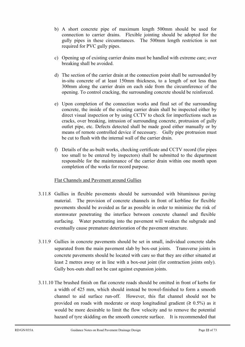
b) A short concrete pipe of maximum length 500mm should be used for connection to carrier drains. Flexible jointing should be adopted for the gully pipes in these circumstances. The 500mm length restriction is not required for PVC gully pipes.
c) Opening up of existing carrier drains must be handled with extreme care; over breaking shall be avoided.
d) The section of the carrier drain at the connection point shall be surrounded by in-situ concrete of at least 150mm thickness, to a length of not less than 300mm along the carrier drain on each side from the circumference of the opening. To control cracking, the surrounding concrete should be reinforced.
e) Upon completion of the connection works and final set of the surrounding concrete, the inside of the existing carrier drain shall be inspected either by direct visual inspection or by using CCTV to check for imperfections such as cracks, over breaking, intrusion of surrounding concrete, protrusion of gully outlet pipe, etc. Defects detected shall be made good either manually or by means of remote controlled device if necessary. Gully pipe protrusion must be cut to flush with the internal wall of the carrier drain.
f) Details of the as-built works, checking certificate and CCTV record (for pipes too small to be entered by inspectors) shall be submitted to the department responsible for the maintenance of the carrier drain within one month upon completion of the works for record purpose.
Flat Channels and Pavement around Gullies
3.11.8 Gullies in flexible pavements should be surrounded with bituminous paving
material. The provision of concrete channels in front of kerbline for flexible pavements should be avoided as far as possible in order to minimize the risk of stormwater penetrating the interface between concrete channel and flexible surfacing. Water penetrating into the pavement will weaken the subgrade and eventually cause premature deterioration of the pavement structure.
3.11.9 Gullies in concrete pavements should be set in small, individual concrete slabs
separated from the main pavement slab by box-out joints. Transverse joints in concrete pavements should be located with care so that they are either situated at least 2 metres away or in line with a box-out joint (for contraction joints only). Gully box-outs shall not be cast against expansion joints.
3.11.10 The brushed finish on flat concrete roads should be omitted in front of kerbs for
a width of 425 mm, which should instead be trowel-finished to form a smooth channel to aid surface run-off. However, this flat channel should not be
provided on roads with moderate or steep longitudinal gradient (≥ 0.5%) as it would be more desirable to limit the flow velocity and to remove the potential hazard of tyre skidding on the smooth concrete surface. It is recommended that

RD/GN/035A Guidance Notes on Road Pavement Drainage Design Page 23 of 73
no flat channel should be provided on roads with longitudinal gradient more than 5%.
3.12 Capacity of Outlet Pipes 3.12.1 As recommended in section 3.9.7, a series of gullies may be constructed at a
single sag point to cater for the flow from the respective catchment. Since the gullies are closely spaced, it is convenient to connect all the gullies into a series for discharging at a single outlet pipe. However, to avoid sterilizing the function of multiple gullies, it is necessary to check the capacity of the outlet pipe. As the drainage system is designed to cater for the ultimate state (i.e. a 5 minute rainstorm with a probability of occurrence of 1 in 50 years from Tables 1B to 1E according the rainfall zone in Figure 1), the outlet pipe should therefore have sufficient capacity to convey the flow intercepted by the gully series under a rainfall intensity of 248 mm/hour in general application (Table 1B) or other design rainfall intensities in Tables 1C to 1E.
3.12.2 The capacity of an outlet pipe can be computed by using the Colebrook-White
equation as shown in Equation (6):
f
sfPP
gRSRR
kgRSAQ
32
255.1
8.14log32
(6)
where QP = pipe capacity (m3/s)
AP = cross-sectional area of the pipe (m2)
g = gravitational acceleration (m/s2) (the typical value is of 9.81 m/s2)
R = hydraulic radius (m) (= pipe diameter/4)
Sf = slope of the pipe
ks = roughness value of the pipe (m) (the typical values for concrete pipe and PVC pipe are 0.0006 m (i.e. 0.6 mm) and 0.00006 m (i.e. 0.06 mm) respectively)
= viscosity of stormwater (m2/s) (the typical value is of 1 x 10⁻⁶
m2/s)
3.12.3 For the required flow capacity of the outlet pipe, it can be computed by using
Equation (7):
AIQG (7)
where QG = required flow capacity of the outlet pipe for the gully series
(m3/s)
RD/GN/035A Guidance Notes on Road Pavement Drainage Design Page 24 of 73
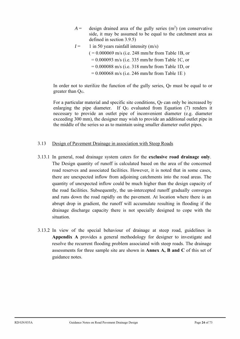
A = design drained area of the gully series (m2) (on conservative side, it may be assumed to be equal to the catchment area as defined in section 3.9.5)
I = 1 in 50 years rainfall intensity (m/s)
( = 0.000069 m/s (i.e. 248 mm/hr from Table 1B, or
= 0.000093 m/s (i.e. 335 mm/hr from Table 1C, or
= 0.000088 m/s (i.e. 318 mm/hr from Table 1D, or
= 0.000068 m/s (i.e. 246 mm/hr from Table 1E )
In order not to sterilize the function of the gully series, QP must be equal to or greater than QG. For a particular material and specific site conditions, QP can only be increased by enlarging the pipe diameter. If QG evaluated from Equation (7) renders it necessary to provide an outlet pipe of inconvenient diameter (e.g. diameter exceeding 300 mm), the designer may wish to provide an additional outlet pipe in the middle of the series so as to maintain using smaller diameter outlet pipes.
3.13 Design of Pavement Drainage in association with Steep Roads
3.13.1 In general, road drainage system caters for the exclusive road drainage only.
The Design quantity of runoff is calculated based on the area of the concerned road reserves and associated facilities. However, it is noted that in some cases, there are unexpected inflow from adjoining catchments into the road areas. The quantity of unexpected inflow could be much higher than the design capacity of the road facilities. Subsequently, the un-intercepted runoff gradually converges and runs down the road rapidly on the pavement. At location where there is an abrupt drop in gradient, the runoff will accumulate resulting in flooding if the drainage discharge capacity there is not specially designed to cope with the situation.
3.13.2 In view of the special behaviour of drainage at steep road, guidelines in Appendix A provides a general methodology for designer to investigate and resolve the recurrent flooding problem associated with steep roads. The drainage assessments for three sample site are shown in Annex A, B and C of this set of guidance notes.
RD/GN/035A Guidance Notes on Road Pavement Drainage Design Page 25 of 73
3.14 Design of Pavement Drainage at Sag Sections of Expressways
3.14.1 Occasional flooding incidents at sag sections of expressways show the transient
inadequacy of prevailing gullies and carrier drains design in tackling the extreme weather conditions. Closure of an expressway section, even partially and for a short duration, would induce highly undesirable traffic impact. A set of guidance is provided in Appendix B to bring in extra provisions in pavement drainage design, on the top of gullies, to cope with possible hazards due to extreme rainfall on expressways.
RD/GN/035A Guidance Notes on Road Pavement Drainage Design Page 26 of 73
4. Design Workflow
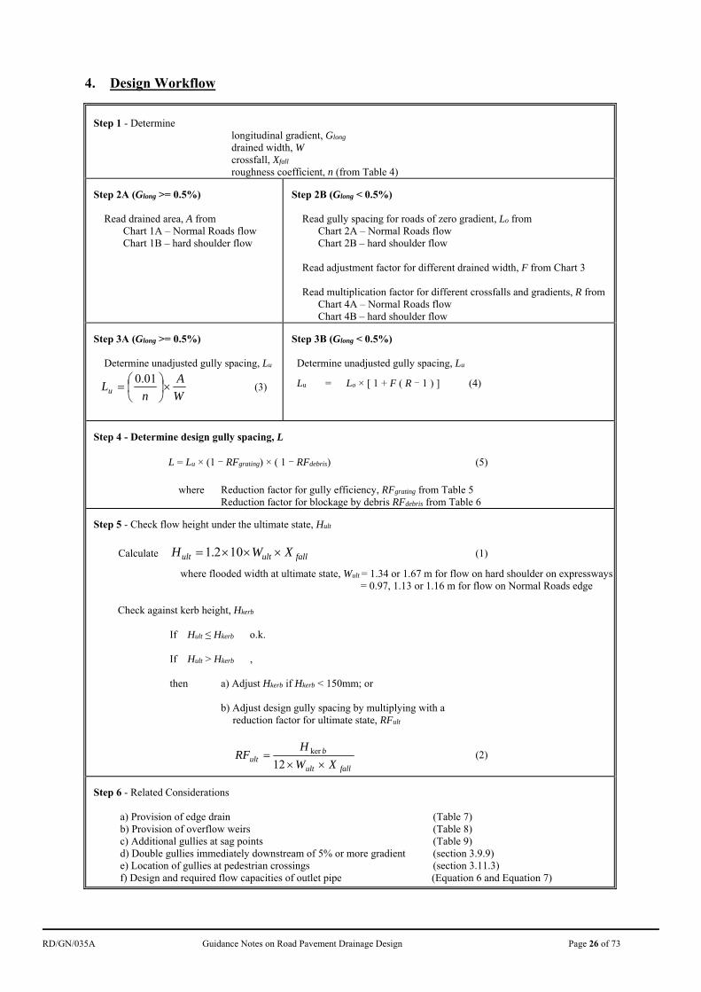
Step 1 - Determine longitudinal gradient, Glong drained width, W crossfall, Xfall roughness coefficient, n (from Table 4) Step 2A (Glong >= 0.5%) Read drained area, A from
Chart 1A – Normal Roads flow Chart 1B – hard shoulder flow
Step 2B (Glong < 0.5%) Read gully spacing for roads of zero gradient, Lo from Chart 2A – Normal Roads flow Chart 2B – hard shoulder flow Read adjustment factor for different drained width, F from Chart 3 Read multiplication factor for different crossfalls and gradients, R from Chart 4A – Normal Roads flow Chart 4B – hard shoulder flow
Step 3A (Glong >= 0.5%) Determine unadjusted gully spacing, Lu
W
A
nLu
01.0 (3)
Step 3B (Glong < 0.5%) Determine unadjusted gully spacing, Lu
Lu = Lo × [ 1 + F ( R - 1 ) ] (4)
Step 4 - Determine design gully spacing, L
L = Lu × (1 - RFgrating) × ( 1 - RFdebris) (5)
where Reduction factor for gully efficiency, RFgrating from Table 5
Reduction factor for blockage by debris RFdebris from Table 6 Step 5 - Check flow height under the ultimate state, Hult
Calculate fallultult XWH 102.1 (1)
where flooded width at ultimate state, Wult = 1.34 or 1.67 m for flow on hard shoulder on expressways= 0.97, 1.13 or 1.16 m for flow on Normal Roads edge
Check against kerb height, Hkerb
If Hult ≤ Hkerb o.k.
If Hult > Hkerb ,
then a) Adjust Hkerb if Hkerb < 150mm; or
b) Adjust design gully spacing by multiplying with a reduction factor for ultimate state, RFult
fallult
bult XW
HRF
12ker (2)
Step 6 - Related Considerations a) Provision of edge drain (Table 7) b) Provision of overflow weirs (Table 8) c) Additional gullies at sag points (Table 9) d) Double gullies immediately downstream of 5% or more gradient (section 3.9.9) e) Location of gullies at pedestrian crossings (section 3.11.3) f) Design and required flow capacities of outlet pipe (Equation 6 and Equation 7)
RD/GN/035A Guidance Notes on Road Pavement Drainage Design Page 27 of 73
Longitudinal Gradient Minimum Crossfall
1% or less 3%
5% or more 3%
between 1% and 5% 2.5%
Table 3: Minimum Crossfalls
Road Surface n
Concrete without flat channel 0.015
Concrete with flat channel 0.013
Bituminous Wearing Course 0.013
Precast block paving 0.015
Stone Mastic Asphalt (SMA) Wearing Course and Friction Course
0.016
Table 4: Roughness Coefficients for Different Types of Road Surface
Type of Grating RFgrating
GA1-450 0%
GA2-325 15%
Table 5: Reduction Factors for Gully Efficiency
Roads / Road Sections RFdebris
Expressways
longitudinal gradient less than 0.5% & near sag points 15%
longitudinal gradient 0.5% or more
near amenity area or rural area 10%
other sections 5%
Normal Roads
longitudinal gradient less than 0.5% 20%
longitudinal gradient 0.5% or more
near sag points or blockage blackspot, e.g. streets with markets or hawkers
20%
near amenity area or rural area 20%
other sections 15%
Table 6: Reduction Factors for Blockage by Debris
RD/GN/035A Guidance Notes on Road Pavement Drainage Design Page 28 of 73
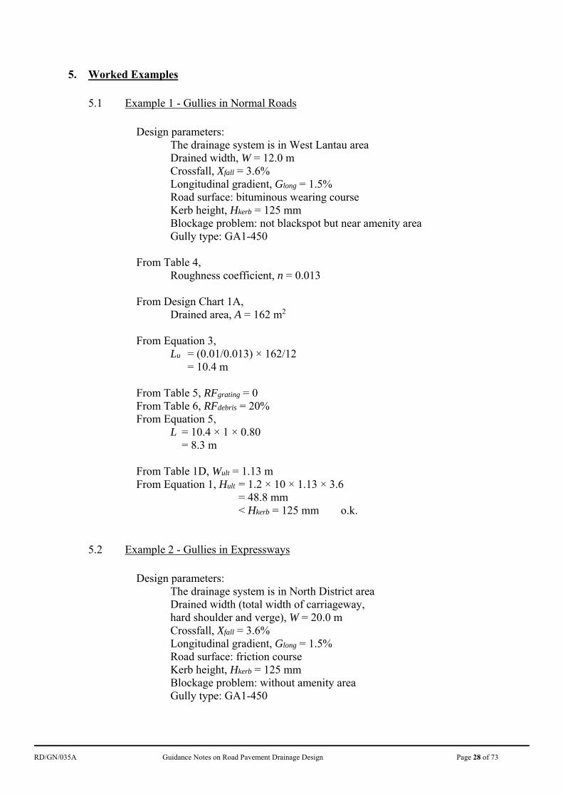
5. Worked Examples 5.1 Example 1 - Gullies in Normal Roads
Design parameters: The drainage system is in West Lantau area
Drained width, W = 12.0 m Crossfall, Xfall = 3.6% Longitudinal gradient, Glong = 1.5% Road surface: bituminous wearing course Kerb height, Hkerb = 125 mm Blockage problem: not blackspot but near amenity area Gully type: GA1-450
From Table 4,
Roughness coefficient, n = 0.013
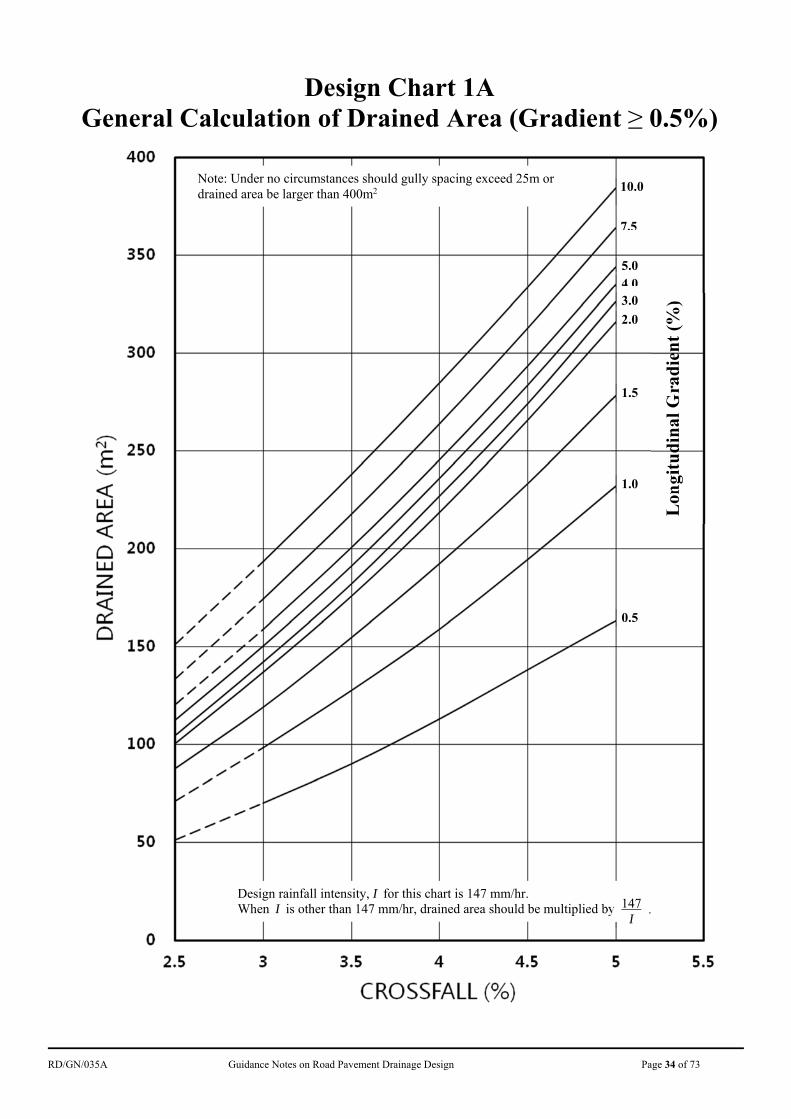
From Design Chart 1A, Drained area, A = 162 m2
From Equation 3,
Lu = (0.01/0.013) × 162/12 = 10.4 m
From Table 5, RFgrating = 0 From Table 6, RFdebris = 20% From Equation 5,
L = 10.4 × 1 × 0.80 = 8.3 m
From Table 1D, Wult = 1.13 m From Equation 1, Hult = 1.2 × 10 × 1.13 × 3.6
= 48.8 mm < Hkerb = 125 mm o.k.
5.2 Example 2 - Gullies in Expressways
Design parameters: The drainage system is in North District area
Drained width (total width of carriageway, hard shoulder and verge), W = 20.0 m Crossfall, Xfall = 3.6% Longitudinal gradient, Glong = 1.5% Road surface: friction course Kerb height, Hkerb = 125 mm Blockage problem: without amenity area Gully type: GA1-450
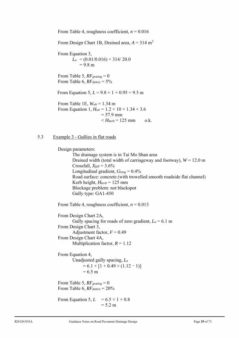
RD/GN/035A Guidance Notes on Road Pavement Drainage Design Page 29 of 73
From Table 4, roughness coefficient, n = 0.016
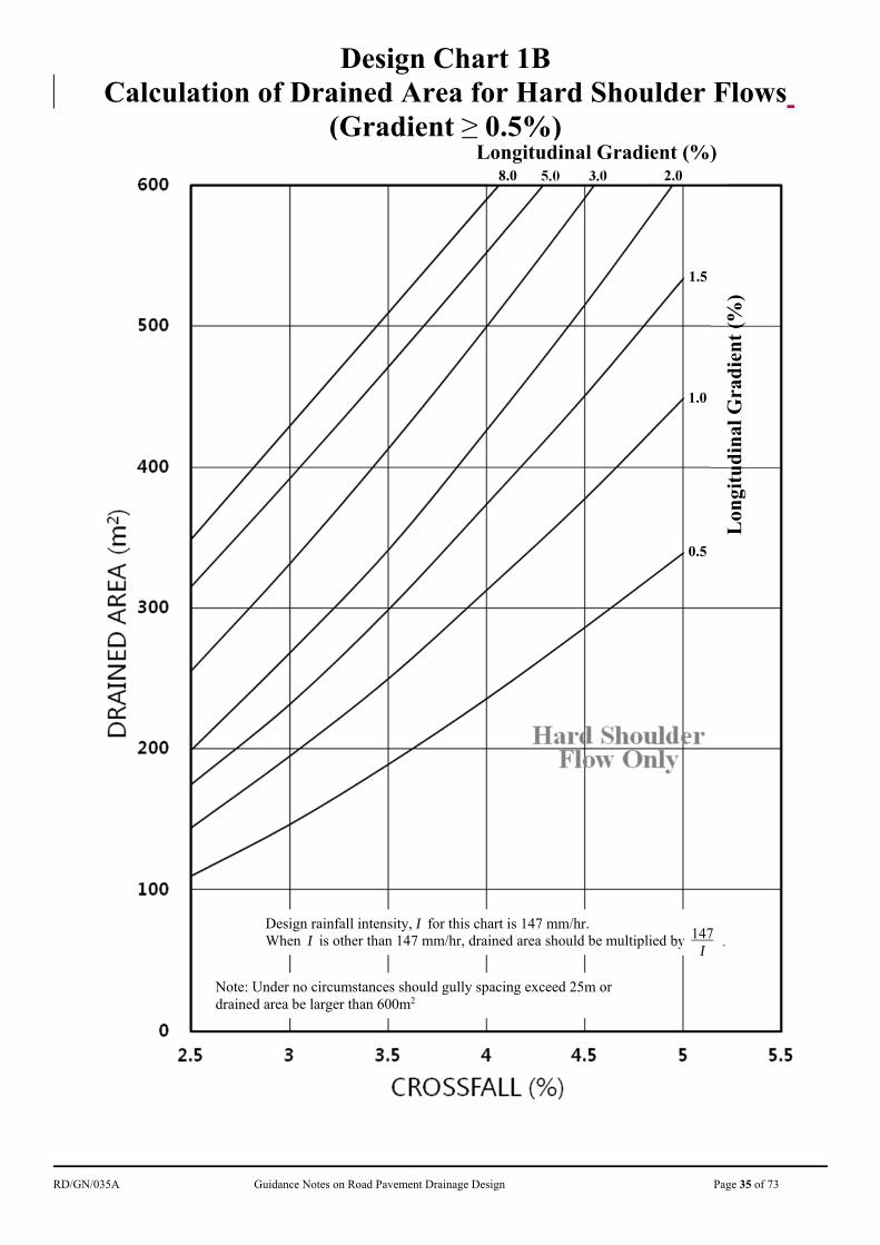
From Design Chart 1B, Drained area, A = 314 m2 From Equation 3,
Lu = (0.01/0.016) × 314/ 20.0 = 9.8 m
From Table 5, RFgrating = 0 From Table 6, RFdebris = 5%
From Equation 5, L = 9.8 × 1 × 0.95 = 9.3 m
From Table 1E, Wult = 1.34 m From Equation 1, Hult = 1.2 × 10 × 1.34 × 3.6
= 57.9 mm < Hkerb = 125 mm o.k.
5.3 Example 3 - Gullies in flat roads
Design parameters: The drainage system is in Tai Mo Shan area
Drained width (total width of carriageway and footway), W = 12.0 m Crossfall, Xfall = 3.6% Longitudinal gradient, Glong = 0.4% Road surface: concrete (with trowelled smooth roadside flat channel) Kerb height, Hkerb = 125 mm Blockage problem: not blackspot Gully type: GA1-450
From Table 4, roughness coefficient, n = 0.013
From Design Chart 2A,
Gully spacing for roads of zero gradient, Lo = 6.1 m From Design Chart 3,
Adjustment factor, F = 0.49 From Design Chart 4A,
Multiplication factor, R = 1.12
From Equation 4, Unadjusted gully spacing, Lu
= 6.1 × [1 + 0.49 × (1.12 - 1)] = 6.5 m
From Table 5, RFgrating = 0 From Table 6, RFdebris = 20%
From Equation 5, L = 6.5 × 1 × 0.8
= 5.2 m
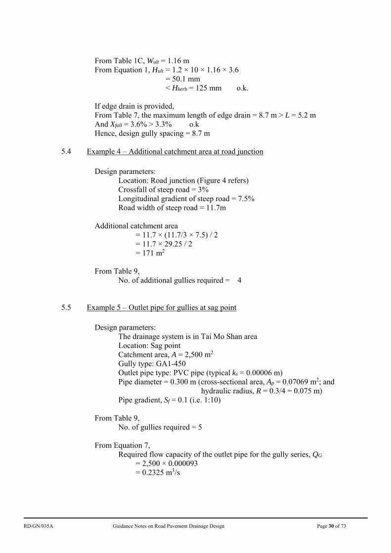
RD/GN/035A Guidance Notes on Road Pavement Drainage Design Page 30 of 73
From Table 1C, Wult = 1.16 m From Equation 1, Hult = 1.2 × 10 × 1.16 × 3.6
= 50.1 mm < Hkerb = 125 mm o.k.
If edge drain is provided, From Table 7, the maximum length of edge drain = 8.7 m > L = 5.2 m And Xfall = 3.6% > 3.3% o.k Hence, design gully spacing = 8.7 m
5.4 Example 4 – Additional catchment area at road junction
Design parameters: Location: Road junction (Figure 4 refers) Crossfall of steep road = 3% Longitudinal gradient of steep road = 7.5% Road width of steep road = 11.7m
Additional catchment area = 11.7 × (11.7/3 × 7.5) / 2 = 11.7 × 29.25 / 2 = 171 m2
From Table 9, No. of additional gullies required = 4
5.5 Example 5 – Outlet pipe for gullies at sag point
Design parameters: The drainage system is in Tai Mo Shan area
Location: Sag point Catchment area, A = 2,500 m2 Gully type: GA1-450 Outlet pipe type: PVC pipe (typical ks = 0.00006 m) Pipe diameter = 0.300 m (cross-sectional area, Ap = 0.07069 m2; and
hydraulic radius, R = 0.3/4 = 0.075 m) Pipe gradient, Sf = 0.1 (i.e. 1:10)
From Table 9, No. of gullies required = 5
From Equation 7, Required flow capacity of the outlet pipe for the gully series, QG
= 2,500 × 0.000093 = 0.2325 m3/s
RD/GN/035A Guidance Notes on Road Pavement Drainage Design Page 31 of 73
From Equation 6, Design flow capacity of the outlet pipe, QP
= 1.0075.081.93207069.0
1.0075.081.932075.0
101255.1
075.08.14
00006.0log
6
= 0.4108 m3/s > 0.2325 m3/s o.k.
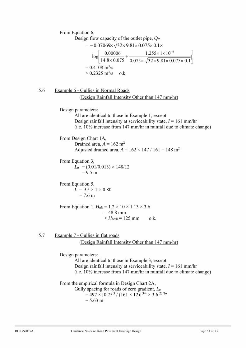
5.6 Example 6 - Gullies in Normal Roads (Design Rainfall Intensity Other than 147 mm/hr)
Design parameters: All are identical to those in Example 1, except Design rainfall intensity at serviceability state, I = 161 mm/hr (i.e. 10% increase from 147 mm/hr in rainfall due to climate change) From Design Chart 1A,
Drained area, A = 162 m2 Adjusted drained area, A = 162 × 147 / 161 = 148 m2
From Equation 3,
Lu = (0.01/0.013) × 148/12 = 9.5 m
From Equation 5,
L = 9.5 × 1 × 0.80 = 7.6 m
From Equation 1, Hult = 1.2 × 10 × 1.13 × 3.6
= 48.8 mm < Hkerb = 125 mm o.k.
5.7 Example 7 - Gullies in flat roads (Design Rainfall Intensity Other than 147 mm/hr)
Design parameters: All are identical to those in Example 3, except Design rainfall intensity at serviceability state, I = 161 mm/hr (i.e. 10% increase from 147 mm/hr in rainfall due to climate change)
From the empirical formula in Design Chart 2A,
Gully spacing for roads of zero gradient, Lo = 497 × [0.75 3 / (161 × 12)] 3/4 × 3.6 23/16
= 5.63 m
RD/GN/035A Guidance Notes on Road Pavement Drainage Design Page 32 of 73
From the empirical formula in Design Chart 3, Adjustment factor, F
= [(147 × 5.43) / (161 × 12)] 7/8 = 0.46 m
From Design Chart 4A,
Multiplication factor, R = 1.12
From Equation 4, Unadjusted gully spacing, Lu
= 5.63 × [1 + 0.46 × (1.12 - 1)] = 5.9 m
From Equation 5, L = 5.9 × 1 × 0.8
= 4.7 m < 5 m Referring to section 3.11.4, covered continuous channels may be considered.
From Equation 1, Hult = 1.2 × 10 × 1.16 × 3.6
= 50.1 mm < Hkerb = 125 mm o.k.
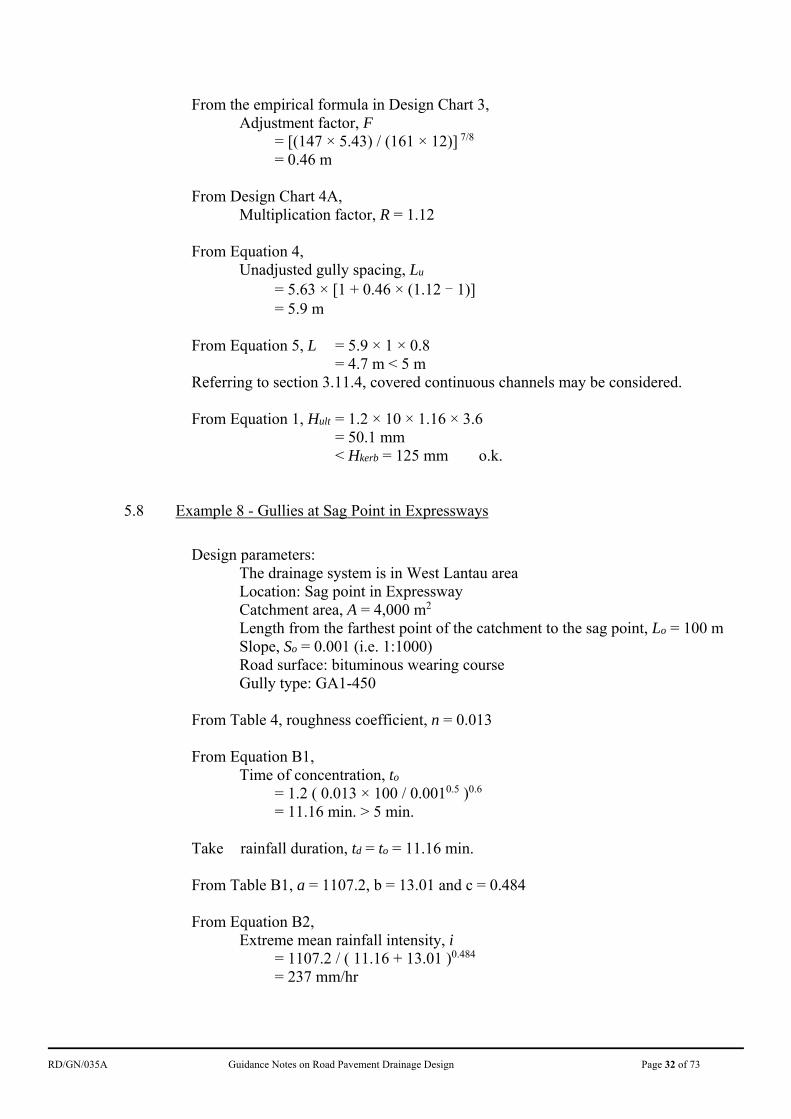
5.8 Example 8 - Gullies at Sag Point in Expressways
Design parameters: The drainage system is in West Lantau area
Location: Sag point in Expressway Catchment area, A = 4,000 m2
Length from the farthest point of the catchment to the sag point, Lo = 100 m Slope, So = 0.001 (i.e. 1:1000) Road surface: bituminous wearing course Gully type: GA1-450
From Table 4, roughness coefficient, n = 0.013
From Equation B1,
Time of concentration, to
= 1.2 ( 0.013 × 100 / 0.0010.5 )0.6 = 11.16 min. > 5 min.
Take rainfall duration, td = to = 11.16 min. From Table B1, a = 1107.2, b = 13.01 and c = 0.484 From Equation B2,
Extreme mean rainfall intensity, i = 1107.2 / ( 11.16 + 13.01 )0.484
= 237 mm/hr

RD/GN/035A Guidance Notes on Road Pavement Drainage Design Page 33 of 73
From Equation B3, Design rainfall intensity, I
= 237 × (1+13.8%)
= 270 mm/hr From Equation B4,
Runoff rate, Q = 0.278 × 1.0 × 270 × (4000 / 106)
= 0.300 m3/s Referring to section B3.1.2(f), For a gully with GA 1-450 double triangular gully grating,
Intake capacity, Qi = 0.11 m3/s No. of gullies required
= Q / Qi = 0.300 / 0.11 = 3 (round up to nearest integer)
While from Table 9, No. gullies required = 6 Hence, 6 nos. of gullies should be provided at the sag point. Referring to section B3.1.4, For a 150 mm diameter drain hole on concrete barrier,
Discharge capacity, = 0.023 m3/s
No. of drain holes required = Q / 0.023 = 0.300 / 0.023 = 14 (round up to nearest integer)
Hence, 14 nos. of drain holes should be provided on the concrete barrier.
RD/GN/035A Guidance Notes on Road Pavement Drainage Design Page 34 of 73
Design Chart 1A General Calculation of Drained Area (Gradient ≥ 0.5%)
Note: Under no circumstances should gully spacing exceed 25m or drained area be larger than 400m2
Lon
gitu
din
al G
rad
ien
t (%
)
10.0
7.5
2.0
1.5
1.0
0.5
5.0 4.03.0
Design rainfall intensity, I for this chart is 147 mm/hr. When I is other than 147 mm/hr, drained area should be multiplied by . 147
I
RD/GN/035A Guidance Notes on Road Pavement Drainage Design Page 35 of 73
Design Chart 1B Calculation of Drained Area for Hard Shoulder Flows
(Gradient ≥ 0.5%)
2.0 3.0 5.0 8.0
Longitudinal Gradient (%)
Note: Under no circumstances should gully spacing exceed 25m or drained area be larger than 600m2
0.5
Lon
gitu
din
al G
rad
ien
t (%
)
1.0
1.5
Design rainfall intensity, I for this chart is 147 mm/hr. When I is other than 147 mm/hr, drained area should be multiplied by . 147
I
RD/GN/035A Guidance Notes on Road Pavement Drainage Design Page 36 of 73
Design Chart 2A – Gully Spacing (Lo) for Flat Roads (Gradient < 0.5%)
3.0 Cro
ssfa
ll, X
fall (
%)
4.0
5.0
Where N = Design flooded width (m) I = Rainfall intensity (mm/hr)
In this chart, N = 0.75 m and I = 147 mm/hr
RD/GN/035A Guidance Notes on Road Pavement Drainage Design Page 37 of 73
Design Chart 2B – Gully Spacing (Lo) Hard Shoulder Flows (Gradient < 0.5%)
3.0 Cro
ssfa
ll, X
fall (
%)
4.0
5.0
Where N = Design flooded width (m) I = Rainfall intensity (mm/hr)
In this chart, N = 1.0 m and I = 147 mm/hr
RD/GN/035A Guidance Notes on Road Pavement Drainage Design Page 38 of 73
Design Chart 3 – Adjustment Factor, F (Gradient < 0.5%)
Where I = Rainfall intensity
In this chart, I = 147
RD/GN/035A Guidance Notes on Road Pavement Drainage Design Page 39 of 73
Design Chart 4A – R Factor Flat Roads (Gradient < 0.5%)
3.0
Cro
ssfa
ll, X
fall (
%)
4.0
5.0
RD/GN/035A Guidance Notes on Road Pavement Drainage Design Page 40 of 73
Design Chart 4B – R Factor Hard Shoulder Flows (Gradient < 0.5%)
3.0
Cro
ssfa
ll, X
fall (
%)
4.0
5.0
RD/GN/035A Guidance Notes on Road Pavement Drainage Design Page 41 of 73
Sketch No. 1 – Edge Drain Details
RD/GN/035A Guidance Notes on Road Pavement Drainage Design Page 42 of 73
Sketch No. 2 – Connection Unit between Edge Drain and Gully
RD/GN/035A Guidance Notes on Road Pavement Drainage Design Page 43 of 73
Sketch No. 3 – Slot Drain
Sketch No. 4 – Kerb Drain
Slot
Cover
Kerb
Footpath
Carriageway
Drain
Flow to gully
Opening
Cover
Kerbline Footpath
Carriageway
Drain
Flow to gully

RD/GN/035A Guidance Notes on Road Pavement Drainage Design Page 44 of 73
APPENDIX A
Design of Pavement Drainage in association with Steep Roads
RD/GN/035A Guidance Notes on Road Pavement Drainage Design Page 45 of 73
A1. Background
A1.1 The following methodology is recommended for design of pavement drainage in association with steep roads with gradient exceeded 5% and with prominent recurrent flooding problem. For minor flooding arising from causes such as local low-lying condition, blockage by debris etc., they should be dealt with by making reference to the relevant sections in this Guidance Notes.
A2. The Methodology A2.1 The designers should note that at steep roads, the runoff is in a very dynamic
behavior. Thus the runoff under extreme rainstorm at a location could flow quickly to another location causing flooding if the resulting location is of insufficient drainage capacity. In view of that, it is recommended that designers should consider the drainage design for steep roads in a wider spectrum with due consideration to the effect of the adjoining areas outside the road reserve. The assessment could be carried out similar to a simplified drainage impact assessment. It comprises several key procedures:
(a) Realistically investigate and evaluate the additional lateral and upstream inflows (if any) into the road area (Steps 1 to 6 below);
(b) With dual consideration of the stormwater received in the road section and the additional lateral/upstream inflow, check the adequacy of the existing drainage facilities at critical locations e.g. sag points (sections 3.9.4 to 3.9.7) or junction (section 3.10), particularly at the location where the road is flattened out (Steps 7 to 8); and
(c) To provide practicable mitigation measures that could be adopted if the drainage capacity of the existing facilities is found to be inadequate (Step 9).
Details of which are further elaborated step-by-step in the sections below. The term “catchment” refers to the area outside the road from which runoff will flow onto the road area.
A2.2 Step 1 - Catchment Delineation
A2.2.1 Use the topographic information on the 1:1,000 survey maps: (a) to delineate the rural uphill catchments along the hill ridges and edges of
slopes; and (b) to delineate the urban catchments along the road boundary.
RD/GN/035A Guidance Notes on Road Pavement Drainage Design Page 46 of 73
A2.3 Step 2 - Identification of the Existing Drainage Provisions
A2.3.1 Identify the existing drainage provisions which are intended for the drainage of the catchment, and the intercepting facilities (if any) at the junction of the catchment with the road area by reviewing the drainage record plans of DSD and conducting site inspection.
A2.4 Step 3 - Fine Tuning the Catchment Boundary
A2.4.1 Fine tune the actual boundary of the catchment outside the road from which runoff will flow onto the road area. It has to assess whether the existing drainage provisions (identified in Step 2) are adequate to intercept and discharge the stormwater runoff received in the catchment before they flow onto the road area, and then demarcate the actual boundary of the catchment.
A2.4.2 The adequacy of the existing drainage provisions should be assessed with due
consideration to avoid over-conservative assumptions. Only the runoff that cannot be discharged into the designated drainage systems should be considered and the assumptions should be validated on site as far as practical.
A2.4.3 It is not uncommon that the runoff may run on the sloping pavement only for a
short distance and then exits the road area; their effect is therefore transient.
A2.5 Step 4 - Evaluation of Time of Concentration
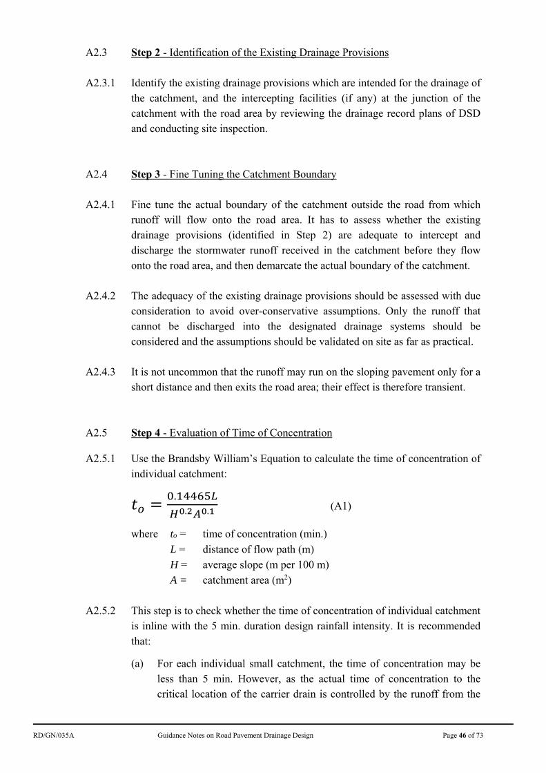
A2.5.1 Use the Brandsby William’s Equation to calculate the time of concentration of individual catchment:
.. . (A1)
where to = time of concentration (min.)
L = distance of flow path (m)
H = average slope (m per 100 m)
A = catchment area (m2)
A2.5.2 This step is to check whether the time of concentration of individual catchment
is inline with the 5 min. duration design rainfall intensity. It is recommended that:
(a) For each individual small catchment, the time of concentration may be less than 5 min. However, as the actual time of concentration to the critical location of the carrier drain is controlled by the runoff from the
RD/GN/035A Guidance Notes on Road Pavement Drainage Design Page 47 of 73
most upstream catchment which in general is longer than 5 min., it is considered conservative, and for simplicity, to use 5 min. duration rainfall intensity for calculating the runoff of the catchment; and
(b) For large catchments of which the time of concentration are longer than 5 min., it may be more pragmatic to use the corresponding time of concentration in calculating the design rainfall intensity (see section B3.1.2(c) and (d) in Appendix B).
A2.6 Step 5 - Evaluation of Runoff Flowrate
A2.6.1 Use the rainfall intensity for 1 in 50 years to calculate the runoff from
individual catchment by the Rational Method. Climate consideration (see section 3.3.1) should be included. Details refer to section B3.1.2(e) in Appendix B).
A2.6.2 For paved catchments, take runoff coefficient, C = 1 that all the rainfall
received in the catchment will become surface runoff. For unpaved area and natural terrain, adopt C = 0.35 which is the maximum value for steep grassland (heavy soil). The value of C for different ground conditions is given in SDM(2018). As most catchments for the purpose of this guidelines are relatively small, it is considered conservative to adopt C = 0.35.
A2.7 Step 6 - Evaluation of Interception Capacity of the Existing Drainage Provisions
A2.7.1 Check the interception capacity of the existing drainage provisions at the
catchment egress point. Reference to the drainage record plans of DSD, supplemented by site surveys if necessary, and this guidance notes should be made to work out the actual net runoff that flows onto the road area.
A2.8 Step 7 - Assessment of Drainage Capacity of the Existing Drainage Provisions
A2.8.1 Assess the drainage capacity of the existing road drainage provisions and the carrier drain at critical locations of the road section and review their adequacy:
(a) Adding the additional runoff compiled in Steps 1 to 6 above to the rainfall received on the corresponding road area, check the adequacy of the existing road drainage facilities (e.g. gullies, channels etc.) with reference to this Guidance Notes.
(b) Check the capacity of the existing carrier drain (see section 3.12.2) at
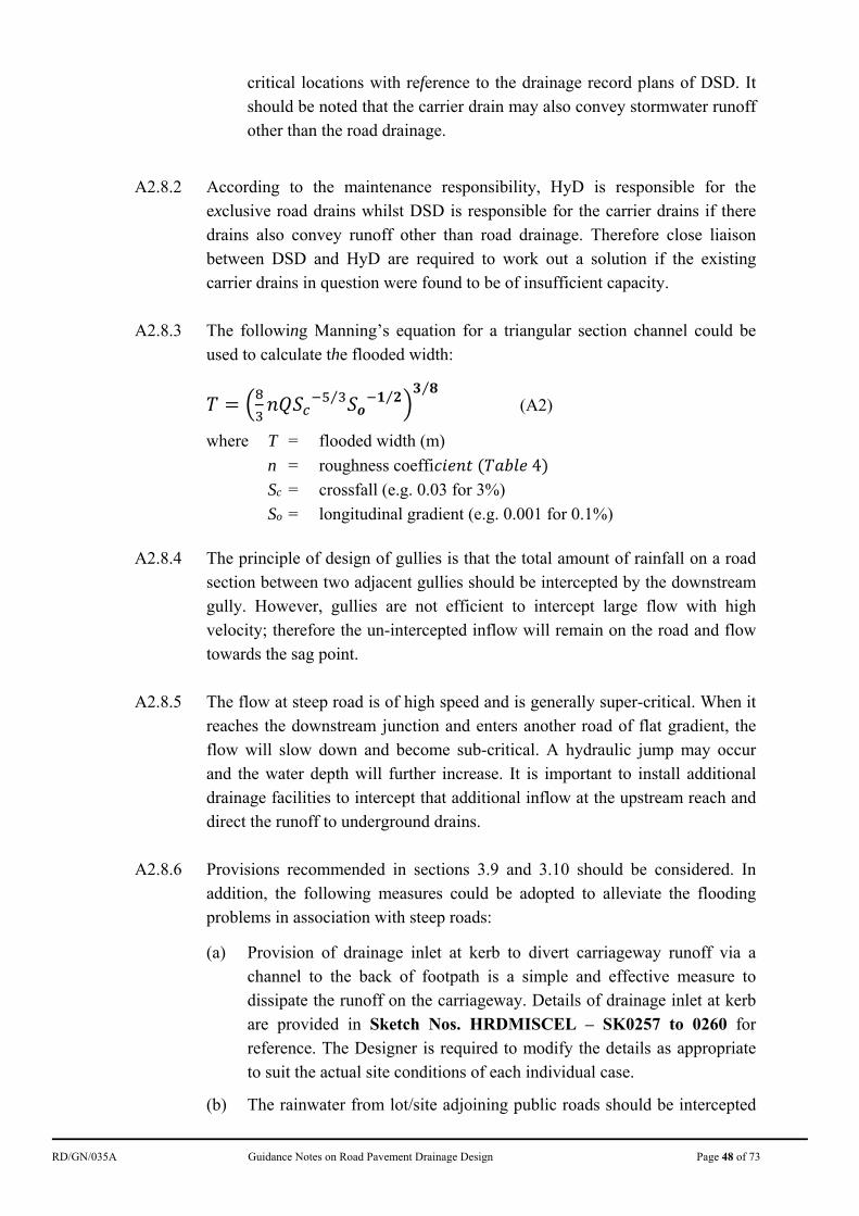
RD/GN/035A Guidance Notes on Road Pavement Drainage Design Page 48 of 73
critical locations with reference to the drainage record plans of DSD. It should be noted that the carrier drain may also convey stormwater runoff other than the road drainage.
A2.8.2 According to the maintenance responsibility, HyD is responsible for the
exclusive road drains whilst DSD is responsible for the carrier drains if there drains also convey runoff other than road drainage. Therefore close liaison between DSD and HyD are required to work out a solution if the existing carrier drains in question were found to be of insufficient capacity.
A2.8.3 The following Manning’s equation for a triangular section channel could be
used to calculate the flooded width:
⁄ ⁄⁄
(A2)
where T = flooded width (m)
n = roughness coeffi 4
Sc = crossfall (e.g. 0.03 for 3%)
So = longitudinal gradient (e.g. 0.001 for 0.1%)
A2.8.4 The principle of design of gullies is that the total amount of rainfall on a road
section between two adjacent gullies should be intercepted by the downstream gully. However, gullies are not efficient to intercept large flow with high velocity; therefore the un-intercepted inflow will remain on the road and flow towards the sag point.
A2.8.5 The flow at steep road is of high speed and is generally super-critical. When it
reaches the downstream junction and enters another road of flat gradient, the flow will slow down and become sub-critical. A hydraulic jump may occur and the water depth will further increase. It is important to install additional drainage facilities to intercept that additional inflow at the upstream reach and direct the runoff to underground drains.
A2.8.6 Provisions recommended in sections 3.9 and 3.10 should be considered. In
addition, the following measures could be adopted to alleviate the flooding problems in association with steep roads:
(a) Provision of drainage inlet at kerb to divert carriageway runoff via a channel to the back of footpath is a simple and effective measure to dissipate the runoff on the carriageway. Details of drainage inlet at kerb are provided in Sketch Nos. HRDMISCEL – SK0257 to 0260 for reference. The Designer is required to modify the details as appropriate to suit the actual site conditions of each individual case.
(b) The rainwater from lot/site adjoining public roads should be intercepted
RD/GN/035A Guidance Notes on Road Pavement Drainage Design Page 49 of 73
before they flow on to the road area, and the requirement should be explicitly stated in the land grant/ engineering conditions as follows:-
(i) For Special Conditions of the lease for private developments, append statement “Storm-water or rain-water falling or flowing on to the lot shall not be allowed to flow on to the surface of public roads” to the relevant clause.
(ii) For the Engineering Conditions of land allocations, append the statement “Storm-water or rain-water from the site shall not be allowed to flow on to the surface of public roads” to the relevant clause.
The purpose is to explicitly state HyD’s requirement that water from the lot/ site shall not be allowed to flow on to the adjoining public roads.
A2.8.7 In general, the flood water depth at kerb is allowed to reach the kerb height of
125 mm under 1 in 50 years design rainfall (see sections 3.4.1 to 3.4.3). For typical crossfall of road pavements of 3%, the corresponding flooded width can reach to about 4 m, which is large and looks like flooding. Besides, for steep roads, the corresponding flow velocity near kerb can reach to about 4 m/s or higher for road gradient of 10% or higher.
A2.8.8 For urban roads, the carrier drains are very often not exclusive in handling the
stormwater runoff from road pavements. In those cases, it is recommended to liaise with DSD to check whether the capacity of the concerned carrier drains are adequate to handle the stormwater runoff from the concerned road pavements together with that from the other design catchments of the carrier drains via the developed mathematical models of DSD.
A2.9 Step 8 - Review on Flooding History
A2.9.1 Review the flooding history and causes of past flooding incidents, and collect information from competent persons.
A2.10 Step 9 - Provision of Improvement Measures
A2.10.1 Provide practicable improvement measures at suitable locations. For example:
(i) intercepting facilities at runoff egress points of significant catchments;
(ii) enhanced gully systems such as more effective road gully arrangement (e.g. provision of inlet at kerb or additional overflow weir) and/or additional gullies;
RD/GN/035A Guidance Notes on Road Pavement Drainage Design Page 50 of 73
(iii) on-site roadside flood storage;
(iv) bypass/excess surface runoff diversion/interception plan at upstream; or
(v) transverse drain, etc.
A2.10.2 If feasible, intercepting measures should be installed away from the road
pavement to minimize traffic interruption. When additional drainage measures to be installed on the road pavement are absolutely necessary, consideration on minimizing the interruption to traffic during initial construction and subsequent maintenance is essential. Since traffic at the very upstream of a road is often less busy than downstream, intercepting measures at the very upstream should be accorded higher priority.
A3. Points for Special Attention A3.1 It is very important to realistically delineate the actual catchments in the
drainage assessment (e.g. overflow/un-intercepted runoff from natural stream course, adjoining lots etc.) because the area of these catchments could be very significant comparing to the area of the road pavement in question. Proper intercepting facilities should be provided to prevent this additional inflow from entering the road area. Discussions amongst relevant parties are required to work out an effective solution.
A3.2 For roads in built-up or urban areas, subject to site observation, it is reasonable
to assume that the surface runoff from roofs of adjoining buildings are properly conveyed to the underground drainage system without traversing the road pavement. Hence, it is suffice to consider only the runoff from the open area of the adjacent lots if there is no proper intercepting facility.
A3.3 In rural areas or locations with large greening areas nearby, a realistic
judgement and site visit to determine actual extent of the possible additional catchments are required. Some catchments, though their sizes appeared not significant, omission of them might lead to overloading of the road drainage system because the quantity of storm water collected by them could still be significant comparing to the concerned road area.
A3.4 If possible and under a safe condition, it would be useful to chart the actual
flow of water runoff on site under heavy rainfall so as to design appropriate mitigation measures.
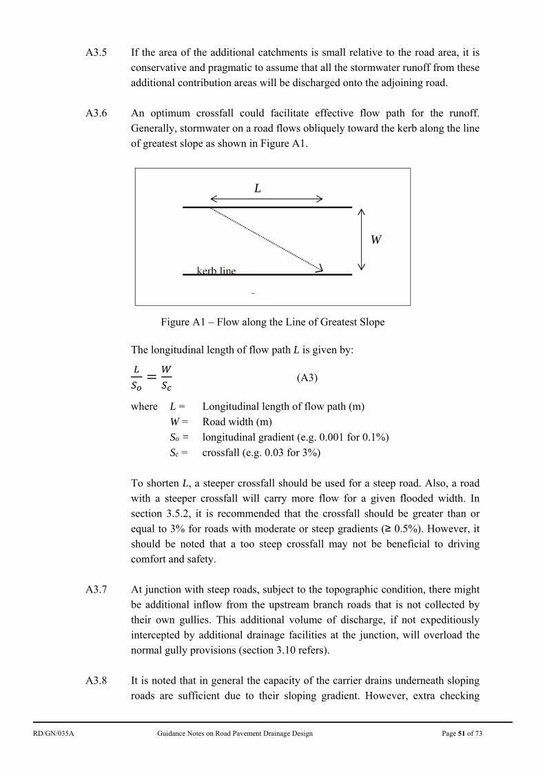
RD/GN/035A Guidance Notes on Road Pavement Drainage Design Page 51 of 73
A3.5 If the area of the additional catchments is small relative to the road area, it is conservative and pragmatic to assume that all the stormwater runoff from these additional contribution areas will be discharged onto the adjoining road.
A3.6 An optimum crossfall could facilitate effective flow path for the runoff.
Generally, stormwater on a road flows obliquely toward the kerb along the line of greatest slope as shown in Figure A1.
Figure A1 – Flow along the Line of Greatest Slope
The longitudinal length of flow path L is given by:
(A3)
where L = Longitudinal length of flow path (m)
W = Road width (m)
So = longitudinal gradient (e.g. 0.001 for 0.1%)
Sc = crossfall (e.g. 0.03 for 3%)
To shorten L, a steeper crossfall should be used for a steep road. Also, a road with a steeper crossfall will carry more flow for a given flooded width. In section 3.5.2, it is recommended that the crossfall should be greater than or
equal to 3% for roads with moderate or steep gradients (≥ 0.5%). However, it should be noted that a too steep crossfall may not be beneficial to driving comfort and safety.
A3.7 At junction with steep roads, subject to the topographic condition, there might
be additional inflow from the upstream branch roads that is not collected by their own gullies. This additional volume of discharge, if not expeditiously intercepted by additional drainage facilities at the junction, will overload the normal gully provisions (section 3.10 refers).
A3.8 It is noted that in general the capacity of the carrier drains underneath sloping
roads are sufficient due to their sloping gradient. However, extra checking
L
W
RD/GN/035A Guidance Notes on Road Pavement Drainage Design Page 52 of 73
should be exercised when the gradients of sloping drains are flattened out. Also some manhole covers might be forced open by the high hydraulic pressure during extreme rainfall condition which is an indication that the downstream drain is of insufficient capacity that may require improvement.
A3.9 Additional gullies are required at some special locations where the road
has/will have gradient change, such as the bottom or near the bottom of the steep road (sections 3.9.8 and 3.9.9 refer).
A3.10 Verge, lay-by and some road widening features could slow down flow as there
is an increase in surface area. Adding gullies at these locations could intercept the runoff more effectively.
A3.11 The connection pipes of multiple gullies should be checked to ensure that they
are constructed and maintained properly. Connection in series of a large number of gullies should be avoided as far as possible. If due to site constraint, it is necessary to connect a gully to another gully instead of directly discharge to an underground carrier drain or manhole, the capacity of the pipes between gullies and the discharge pipe from the final gully of the series to the carrier drain/manhole must be checked (section 3.12 refers).
A3.12 The tidal effect on the trunk drain at the lowest point of the steep roads should
be checked. As locations which are low-lying and tidal effect is significant, consideration should be given to intercept the runoff at a higher location and divert it to another location if possible.
A3.13 The maintenance staff should note the importance of proper maintenance of
the drainage system, especially at some watercourse intakes which are vulnerable to blockage by debris.
A4. Suggested Mitigation Measures A4.1 It is more effective to intercept the lateral/upstream inflow before it reaches the
road pavement, e.g. for runoff from roadside slopes, surface channels along the toes are effective intercepting measures.
A4.2 If additional drainage provision on the road pavement is inevitable, priority
should be given on applying the traditional road gully system design because of its simplicity in application, less disruption to the traffic and easy maintenance. The design procedures are mentioned in sections 3.1 to 3.10.
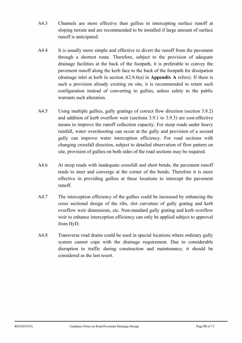
RD/GN/035A Guidance Notes on Road Pavement Drainage Design Page 53 of 73
A4.3 Channels are more effective than gullies in intercepting surface runoff at sloping terrain and are recommended to be installed if large amount of surface runoff is anticipated.
A4.4 It is usually more simple and effective to divert the runoff from the pavement
through a shortest route. Therefore, subject to the provision of adequate drainage facilities at the back of the footpath, it is preferable to convey the pavement runoff along the kerb face to the back of the footpath for dissipation (drainage inlet at kerb in section A2.8.6(a) in Appendix A refers). If there is such a provision already existing on site, it is recommended to retain such configuration instead of converting to gullies, unless safety to the public warrants such alteration.
A4.5 Using multiple gullies, gully gratings of correct flow direction (section 3.8.2)
and addition of kerb overflow weir (sections 3.9.1 to 3.9.3) are cost-effective means to improve the runoff collection capacity. For steep roads under heavy rainfall, water overshooting can occur at the gully and provision of a second gully can improve water interception efficiency. For road sections with changing crossfall direction, subject to detailed observation of flow pattern on site, provision of gullies on both sides of the road sections may be required.
A4.6 At steep roads with inadequate crossfall and short bends, the pavement runoff
tends to steer and converge at the corner of the bends. Therefore it is more effective in providing gullies at these locations to intercept the pavement runoff.
A4.7 The interception efficiency of the gullies could be increased by enhancing the
cross sectional design of the ribs, slot curvature of gully grating and kerb overflow weir dimensions, etc. Non-standard gully grating and kerb overflow weir to enhance interception efficiency can only be applied subject to approval from HyD.
A4.8 Transverse road drains could be used in special locations where ordinary gully
system cannot cope with the drainage requirement. Due to considerable disruption to traffic during construction and maintenance, it should be considered as the last resort.
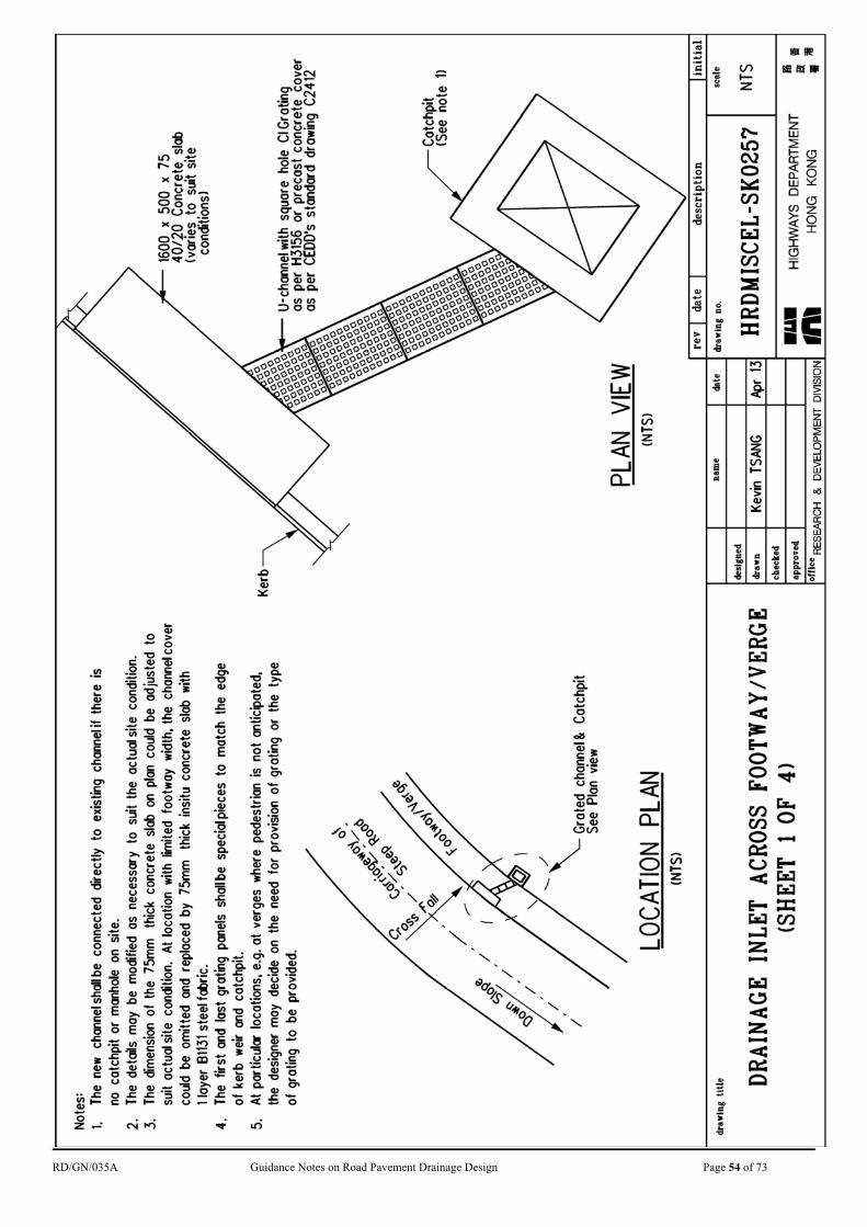
RD/GN/035A Guidance Notes on Road Pavement Drainage Design Page 54 of 73
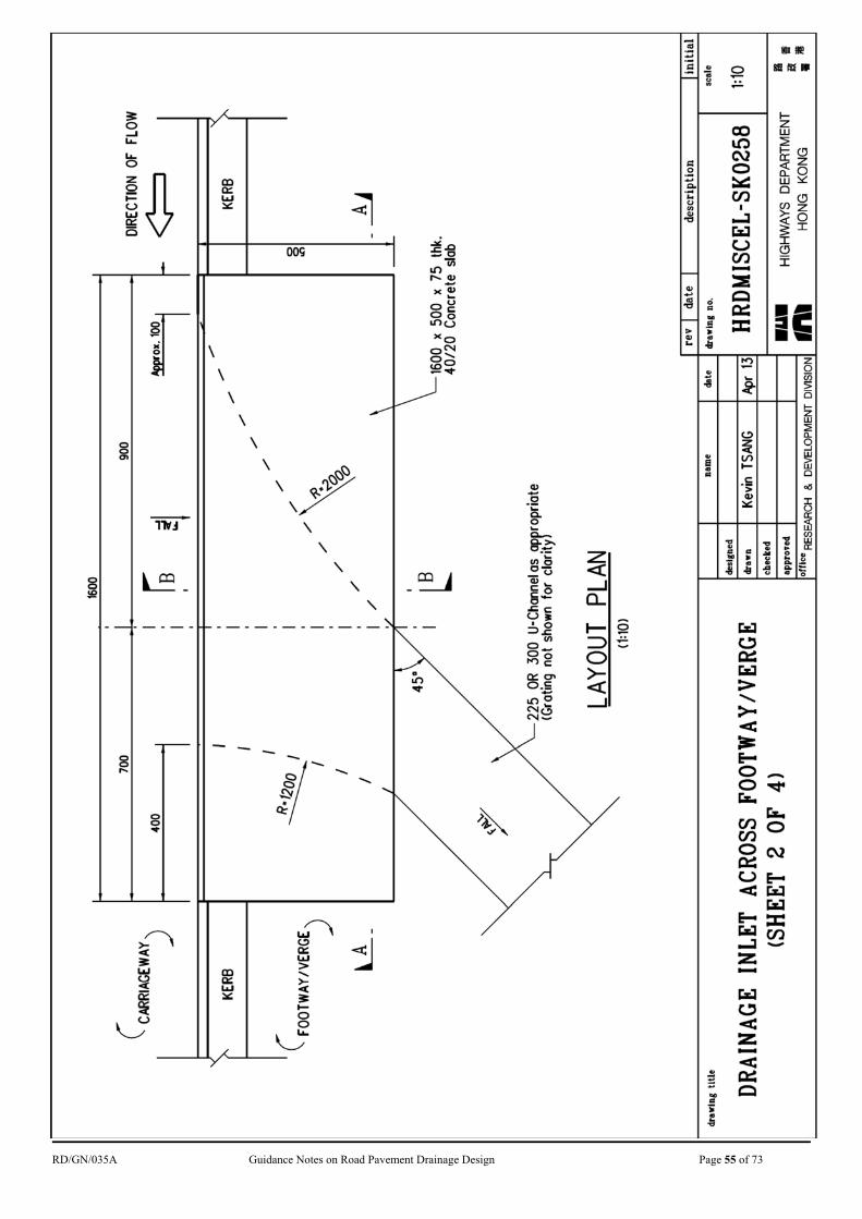
RD/GN/035A Guidance Notes on Road Pavement Drainage Design Page 55 of 73
RD/GN/035A Guidance Notes on Road Pavement Drainage Design Page 56 of 73
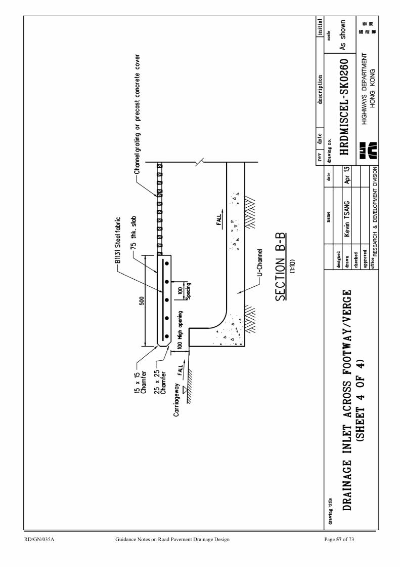
RD/GN/035A Guidance Notes on Road Pavement Drainage Design Page 57 of 73
RD/GN/035A Guidance Notes on Road Pavement Drainage Design Page 58 of 73
APPENDIX B
Design of Pavement Drainage at Sag Sections of Expressways
RD/GN/035A Guidance Notes on Road Pavement Drainage Design Page 59 of 73
B1 General Principles
B1.1 Road pavement drainage is designed to accommodate rainfall intensity for heavy rainstorms with a probability of 1 in 50 years occurrence under ultimate state and twice per year under serviceability state respectively (section 3.1.1 refers). The same design return periods apply to both expressways and normal roads.
B1.2 Occasional flooding incidents at sag sections of expressways show the
transient inadequacy of prevailing gullies and carrier drains design in tackling the extreme weather conditions. Closure of an expressway section, even partially and for a short duration, would induce highly undesirable traffic impact. It is therefore necessary to bring in extra provisions in pavement drainage design, on the top of gullies, to cope with possible hazards due to extreme rainfall on expressways.
B1.3 While designing a contingency discharge system, designers shall as far as
practicable identify and provide an alternative drain path to rather than simply connecting contingency outlets back to the same carrier drains into which the principal gully system is discharged.
B1.4 In consideration of information in hand, it is advisable to continue adopting the
storm return periods mentioned in B1.1 for design of pavement drainage. That said, with the contingency discharge measures stipulated in this set of guidelines properly implemented, the pavement drainage systems would become more robust and effective in coping with extreme weather conditions. In alleviating the risk of road closure due to flooding, such measures also reduce the chance of any sudden proliferation of kerbside flooding zone during transient rainstorm of extremely high intensity which would affect the safety of road traffic.
B2 Applications B2.1 This set of guidelines intends to stipulate additional design requirements
including, inter alia, contingency discharge measures for pavement drainage at sag sections of expressways.
B2.2 New drainage design on expressways or retrofitting design for drainage
modification on existing expressways shall take account of this set of guidelines. If site condition warrants, the principles and recommended measures of this set of guidelines may also be applied on normal roads.
RD/GN/035A Guidance Notes on Road Pavement Drainage Design Page 60 of 73
B2.3 For works contracts already in the implementation stage, the actual scope of adopting this set of guidelines may be determined with due consideration of constraints including site geometry, downstream capacity, budget and other risk factors.
B3 Additional Design Requirements
B3.1 Design Catchment of Gullies and Connection Pipes at Sag Points
B3.1.1 In designing the hydraulic capacity of the discharge pipes and number of gullies at the sag point of a concave vertical alignment, a conservative assumption shall be made, where technically feasible, that all upstream gullies (up to the crests on both ends of the sag section) are blocked so that the gullies and the discharge system at the sag point are designed to collect all the surface runoff from upstream.
B3.1.2 The number of gullies to be required at sag points can be determined from the
following approach:
(a) Delineate the catchment which should include the road surface between crests on either side of the sag point.
(b) Use Yen and Chow’s (1983) Simplified Formula to calculate the time of concentration:
1.2 .
. (B1)
where to = time of concentration (min.) Lo = length from the farthest point of the catchment to the
sag point (m) n = roughness coefficient (Table 4) So = Slope = [level of farthest crest – level of sag point]/Lo
for simplification
(c) For the calculated time of concentration longer than 5 minutes, adopt the calculated time of concentration as the design rainstorm duration. For calculated time of concentration equal to or less than 5 minutes, adopt 5 minutes as the rainstorm duration.
(d) The extreme mean rainfall intensity should be calculated for 1 in 50 years return period by using Equation (B2):
(B2)
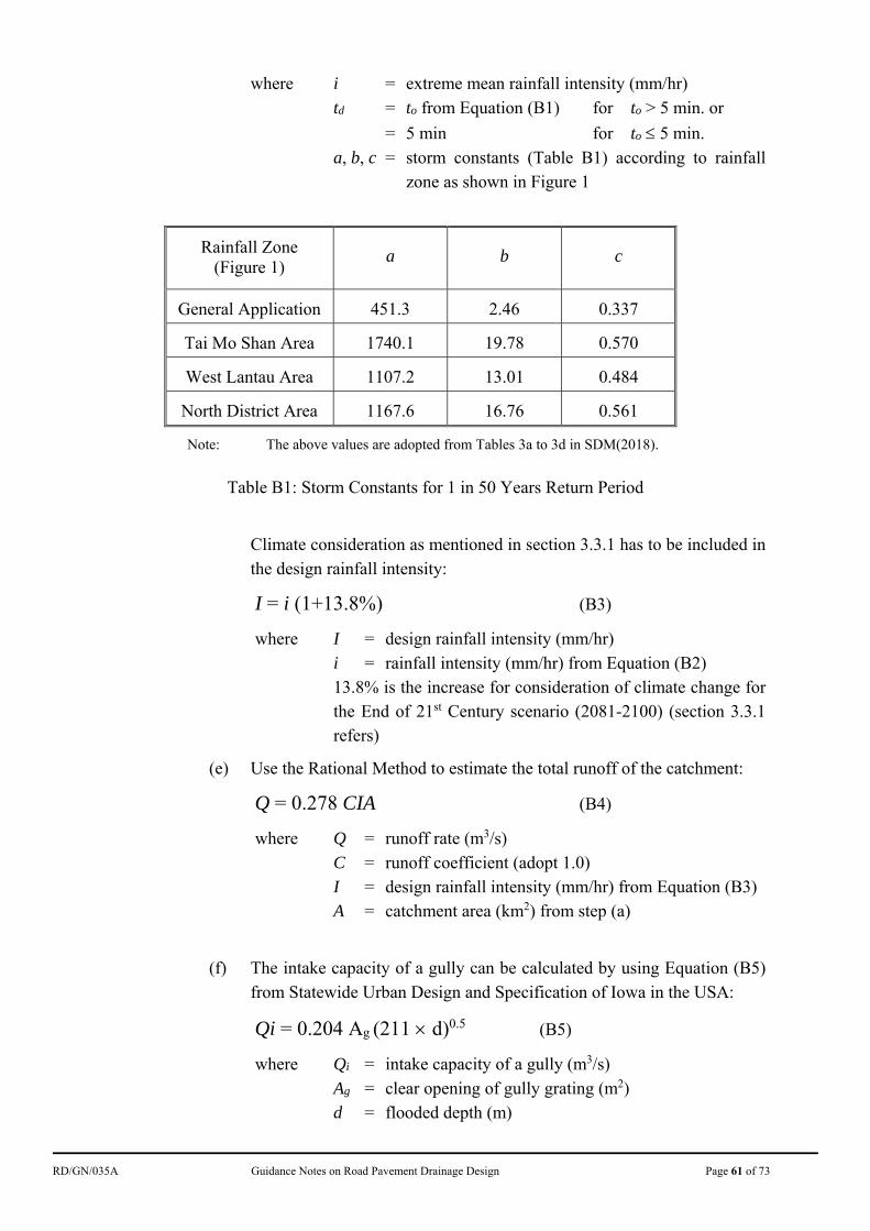
RD/GN/035A Guidance Notes on Road Pavement Drainage Design Page 61 of 73
where i = extreme mean rainfall intensity (mm/hr) td = to from Equation (B1) for to > 5 min. or
= 5 min for to 5 min.
a, b, c = storm constants (Table B1) according to rainfall zone as shown in Figure 1
Rainfall Zone
(Figure 1) a b c
General Application 451.3 2.46 0.337
Tai Mo Shan Area 1740.1 19.78 0.570
West Lantau Area 1107.2 13.01 0.484
North District Area 1167.6 16.76 0.561
Note: The above values are adopted from Tables 3a to 3d in SDM(2018).
Table B1: Storm Constants for 1 in 50 Years Return Period
Climate consideration as mentioned in section 3.3.1 has to be included in the design rainfall intensity:
I = i (1+13.8%) (B3)
where I = design rainfall intensity (mm/hr) i = rainfall intensity (mm/hr) from Equation (B2) 13.8% is the increase for consideration of climate change for
the End of 21st Century scenario (2081-2100) (section 3.3.1 refers)
(e) Use the Rational Method to estimate the total runoff of the catchment:
Q = 0.278 CIA (B4)
where Q = runoff rate (m3/s) C = runoff coefficient (adopt 1.0) I = design rainfall intensity (mm/hr) from Equation (B3) A = catchment area (km2) from step (a)
(f) The intake capacity of a gully can be calculated by using Equation (B5) from Statewide Urban Design and Specification of Iowa in the USA:
Qi = 0.204 Ag (211 d)0.5 (B5)
where Qi = intake capacity of a gully (m3/s) Ag = clear opening of gully grating (m2) d = flooded depth (m)
RD/GN/035A Guidance Notes on Road Pavement Drainage Design Page 62 of 73
For 125 mm flooded depth (i.e. kerb height), the intake capacity of a gully with GA 1-450 double triangular gully grating can be taken as 0.11 m3/s.
The number of gullies required is obtained by dividing the total runoff with the intake capacity of a single gully and should not be less than that stipulated in section 3.9.7.
B3.1.3 To cope with a large catchment, a continuous grated channel (section 3.11.4)
or a series of gullies in vicinity of the sag point would be resulted.
B3.1.4 For typical cross section of expressway as shown in Diagram 6.3.3.1 of Transport Planning and Design Manual (TPDM) Volume 2 Chapter 6 (but with solid concrete barrier at the outer edge) with 2.5% crossfall installed with 150 mm diameter drain holes through the concrete barrier, the discharge capacity of each drain hole can be taken as 0.023 m3/s. The number of drain holes required is obtained by dividing the total runoff with the capacity of a single drain hole.
B3.1.5 For other cross section and drain hole arrangement, the designer should use
appropriate hydraulic formula to calculate the number of drain holes required to maintain at least one traffic lane free from flooding.
B3.2 Contingency Discharge Measures B3.2.1 Investigations on flooding incidents on expressways reveal that the presence of
continuous concrete barriers, central dividers and concrete upstands of noise barriers/enclosures inadvertently prevent the surface runoff from discharging off the expressways and lead to flooding at sag sections in case the gullies and carrier drains, as the only discharge points, do not function properly. It is also observed that open channels along verges, if discharged to an alternative outlet, can serve as an effective contingency alleviating measure under extreme situations.
B3.2.2 Depending on individual site conditions, designers shall include an appropriate
combination of contingency discharge measures at sag sections to assure thoroughfare be maintained along expressways even under extreme weather conditions. The following measures can serve as typical reference, although they may not necessarily be exhaustive:
RD/GN/035A Guidance Notes on Road Pavement Drainage Design Page 63 of 73
(a) Roadside Channels B3.2.3 Open channels can have large hydraulic capacity, high drainage efficiency, and
any blockage of which can be easily identified during daily inspection of the expressways. In view of these advantages, it is recommended to provide roadside channels at the verge of expressways where feasible. Roadside channels (for examples, toe channel of roadside slopes) shall be designed to prevent runoff on the adjacent area/slope from flowing onto the expressway and causing flooding. They can also serve as the contingency measure to receive surface flow on the carriageway overtopping the kerbs or discharging from drain holes through roadside barriers and other intermittent drainage outlets under extreme situations. Details are further elaborated in sections B3.2.5 to B3.2.8 and B3.2.10 below.
B3.2.4 The roadside channels are a vital part of the contingency discharge measures
and the designer shall ensure their hydraulic capacities be adequate for discharging all the anticipated runoff from a heavy rainstorms with a probability of 1 in 50 years.
(b) Drain holes through roadside barriers B3.2.5 Continuous roadside barriers could block the flow of surface runoff away from
the carriageway area in case of extreme weather conditions or malfunctioning of underground pavement drainage system. From the flood-protection point of view, provision of continuous barriers without gaps or drainage openings in particular at or near sag point should be avoided. Since open gap in roadside barriers may affect traffic safety, drain holes through roadside barriers, located slightly above the adjoining road level, should be provided to allow the discharge of runoff away from the expressway under extreme weather conditions. In normal situation, kerbside gullies could effectively drain the surface runoff. When the surface water floods to the level of the drain holes, the drain holes provide alternative drain paths for the discharge of the runoff and reduce the flood risk of the expressway.
B3.2.6 Drain holes shall be properly orientated to streamline the incoming flow, e.g.
perpendicular to the traffic direction along sag and levelled sections, or at an angle of 45° from the kerbside flow direction when the longitudinal gradient is obvious. Shapes of drain holes may be rectangular, oval, circular or others to suit the barrier design and/or necessity of specific aesthetic/traffic noise requirements, provided that the integrity and functionality of the roadside restraint system must be maintained. Preferably overflow weirs should be provided as shown in Sketch Nos. HRDMISCEL-SK0264 and 0265 to
RD/GN/035A Guidance Notes on Road Pavement Drainage Design Page 64 of 73
protect drain holes from blockage by debris. Detailed approach for calculating the required number of circular drain holes through roadside barriers in the vicinity of the sag point is included in sections B3.1.2 and B3.1.4 and is illustrated by Example 8 in section 5.8. The designer may wish to adopt other drain hole shapes so as to enlarge the hole size as far as possible. In the circumstances, the designer should evaluate the drain hole capacity and required number of holes according to established hydraulic theories.
B3.2.7 For sag sections of large catchment areas, it is advisable to provide drain holes
through barriers at convenient locations considerably upstream of the sag point, so that runoff would not be concentrated to the sag point even if the upstream gullies are not performing effectively.
B3.2.8 In general, drain holes through roadside barriers shall be discharged to
channels at the rear side of the barriers (see Sketch No. HRDMISCEL-SK0264). If site conditions allow, it is recommended that the estimated flow from the entire sag section of the carriageway shall be included in designing the hydraulic capacity of the roadside channels. A few salient points on discharge of drain holes across barriers under different topographies are deliberated below for designer’s reference:
(i) Sag sections of expressways abutting uphill slopes
The designer shall take appropriate design precautions to avoid any backwater flow from the roadside channel onto the expressway including, for instance, lowering the invert level of the roadside channel, specifying the gradient of drain holes to fall toward the top of the roadside channel, etc.
(ii) Sag sections of expressways adjacent to downhill slopes
Runoff discharging through the drain holes and crest channel can go along the slope channels, to the catch pits at slope toe and ultimately enter the downhill drainage system.
The estimated overflow from the expressway under contingency situations should be catered for in the design of the slope drainage and downstream outlets.
(iii) Sag sections of expressways on bridge structures
Provision of an additional channel alongside a bridge structure for collecting contingency discharge from the carriageway may not be cost effective. In the circumstances, direct discharge of flood water through the drain holes across barriers can be considered provided the area underneath the bridge structure is not vulnerable.
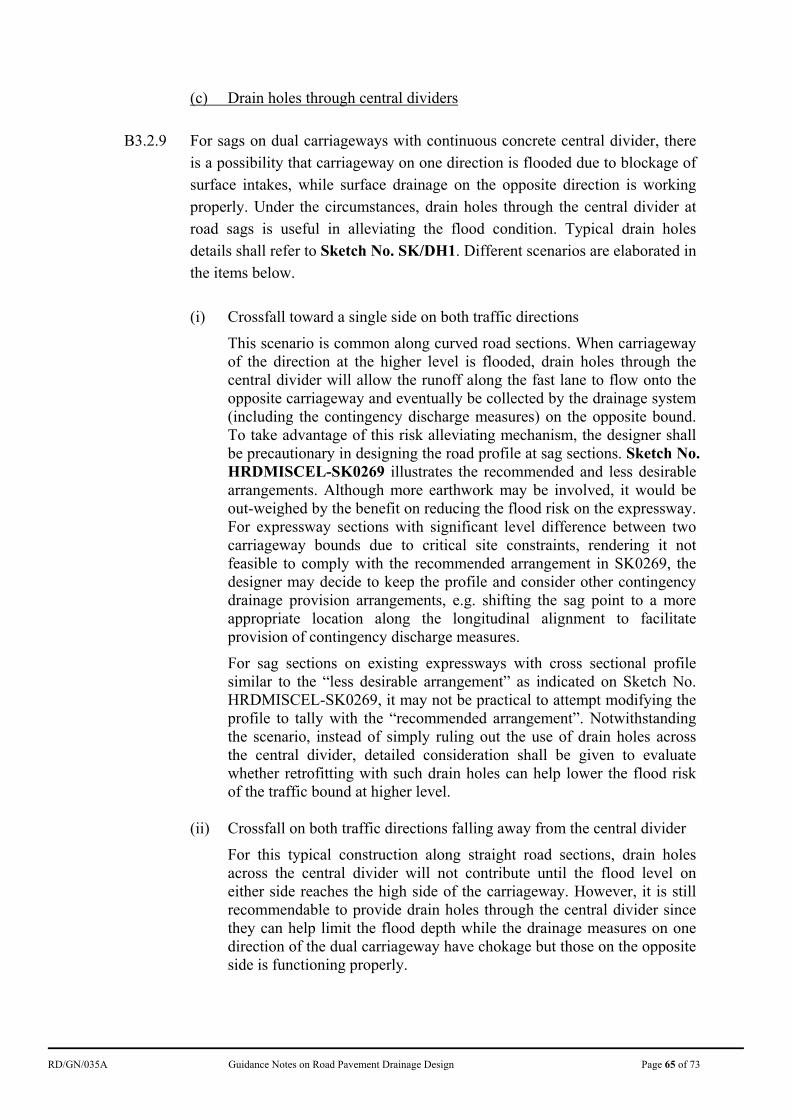
RD/GN/035A Guidance Notes on Road Pavement Drainage Design Page 65 of 73
(c) Drain holes through central dividers
B3.2.9 For sags on dual carriageways with continuous concrete central divider, there
is a possibility that carriageway on one direction is flooded due to blockage of surface intakes, while surface drainage on the opposite direction is working properly. Under the circumstances, drain holes through the central divider at road sags is useful in alleviating the flood condition. Typical drain holes details shall refer to Sketch No. SK/DH1. Different scenarios are elaborated in the items below.
(i) Crossfall toward a single side on both traffic directions
This scenario is common along curved road sections. When carriageway of the direction at the higher level is flooded, drain holes through the central divider will allow the runoff along the fast lane to flow onto the opposite carriageway and eventually be collected by the drainage system (including the contingency discharge measures) on the opposite bound. To take advantage of this risk alleviating mechanism, the designer shall be precautionary in designing the road profile at sag sections. Sketch No. HRDMISCEL-SK0269 illustrates the recommended and less desirable arrangements. Although more earthwork may be involved, it would be out-weighed by the benefit on reducing the flood risk on the expressway. For expressway sections with significant level difference between two carriageway bounds due to critical site constraints, rendering it not feasible to comply with the recommended arrangement in SK0269, the designer may decide to keep the profile and consider other contingency drainage provision arrangements, e.g. shifting the sag point to a more appropriate location along the longitudinal alignment to facilitate provision of contingency discharge measures.
For sag sections on existing expressways with cross sectional profile similar to the “less desirable arrangement” as indicated on Sketch No. HRDMISCEL-SK0269, it may not be practical to attempt modifying the profile to tally with the “recommended arrangement”. Notwithstanding the scenario, instead of simply ruling out the use of drain holes across the central divider, detailed consideration shall be given to evaluate whether retrofitting with such drain holes can help lower the flood risk of the traffic bound at higher level.
(ii) Crossfall on both traffic directions falling away from the central divider
For this typical construction along straight road sections, drain holes across the central divider will not contribute until the flood level on either side reaches the high side of the carriageway. However, it is still recommendable to provide drain holes through the central divider since they can help limit the flood depth while the drainage measures on one direction of the dual carriageway have chokage but those on the opposite side is functioning properly.
RD/GN/035A Guidance Notes on Road Pavement Drainage Design Page 66 of 73
(d) Intermittent drainage outlets at kerbs
B3.2.10 Under extreme conditions, there would be a considerable amount of surface runoff bypassing intermediate gullies along an inclined road section and accumulating at the sag point. This will increase the loading on the drainage system at the sag points and induce the chance of flooding. To relieve such surging demand on the drainage system at the sag point, intermittent drainage outlets at kerbs (see Sketch No. HRDMISCEL-SK0263) shall be provided at all convenient points over the middle of two consecutive gullies along the upstream of the sag point to effectively divert the surface runoff from the carriageway to roadside channels before reaching the sag point. Such provisions can also effectively alleviate any sudden proliferation of kerbside flooding zone during transient rainstorm of extremely high intensity.
(e) Enlarged overflow weir at concrete profile barriers
B3.2.11 To further enhance the effectiveness of overflow weirs under large flood depths, a special design as shown in Sketch Nos. HRDMISCEL-SK0265 and 0266 shall be adopted for overflow weirs to be installed along the concrete profile barriers at sag points. As mentioned in section B3.2.6, drain holes through concrete profile barriers should preferably be provided behind overflow weirs to reduce their visual impact and protect them from blockage by debris.
B4 Outlets Reliability B4.1 To minimize the risk of flooding at sag sections of expressways, the reliability
of drainage outlets shall be duly considered. Inadequate hydraulic capacity or blockage of the downstream drainage will hamper the effectiveness of the entire road drainage system. Small size underground pipe is more susceptible to blockage and the blockage cannot be easily identified until flooding occurs. Hence, it is desirable to design the drainage path from the sag point to trunk drains as short as technically feasible, in particular for the drainage path of the contingency discharge measures. In general, culverts/channels belonging to the Urban Drainage Trunk System or Main Rural Catchment Drainage Channel as defined in the SDM(2018) Section 6.6 would have larger hydraulic capacity, be unlikely to be affected by the backwater and have lower risk of blockage.
B4.2 To diversify risk, outlet for the contingency discharge system shall not simply
merge to that of the principal gullies system wherever possible. If a trunk drain downstream is the common outlet for both systems, it is still recommended to
RD/GN/035A Guidance Notes on Road Pavement Drainage Design Page 67 of 73
design a separate path for connecting the contingency discharge to the trunk drain.
B4.3 The above-mentioned contingency discharge measures are intended to
supplement the principal gully systems in case of extreme situations. If the downstream facilities are not specifically designed to take up the contingency discharge, incidental overloading somewhere at the downstream may be resulted. In case the downstream capacity cannot be sufficiently enlarged to cope with the entire anticipated contingency discharge, the designed number and/or size of the contingency discharge measures should be refined such that the downstream facilities will not be overloaded.
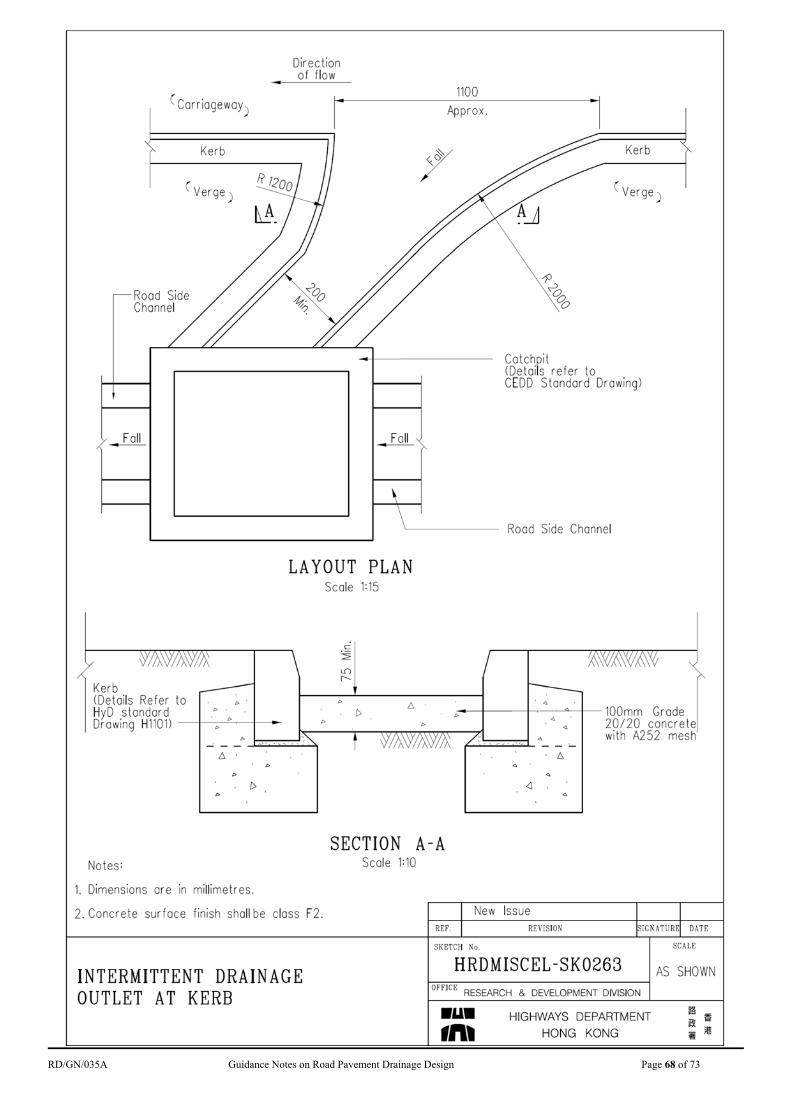
RD/GN/035A Guidance Notes on Road Pavement Drainage Design Page 68 of 73
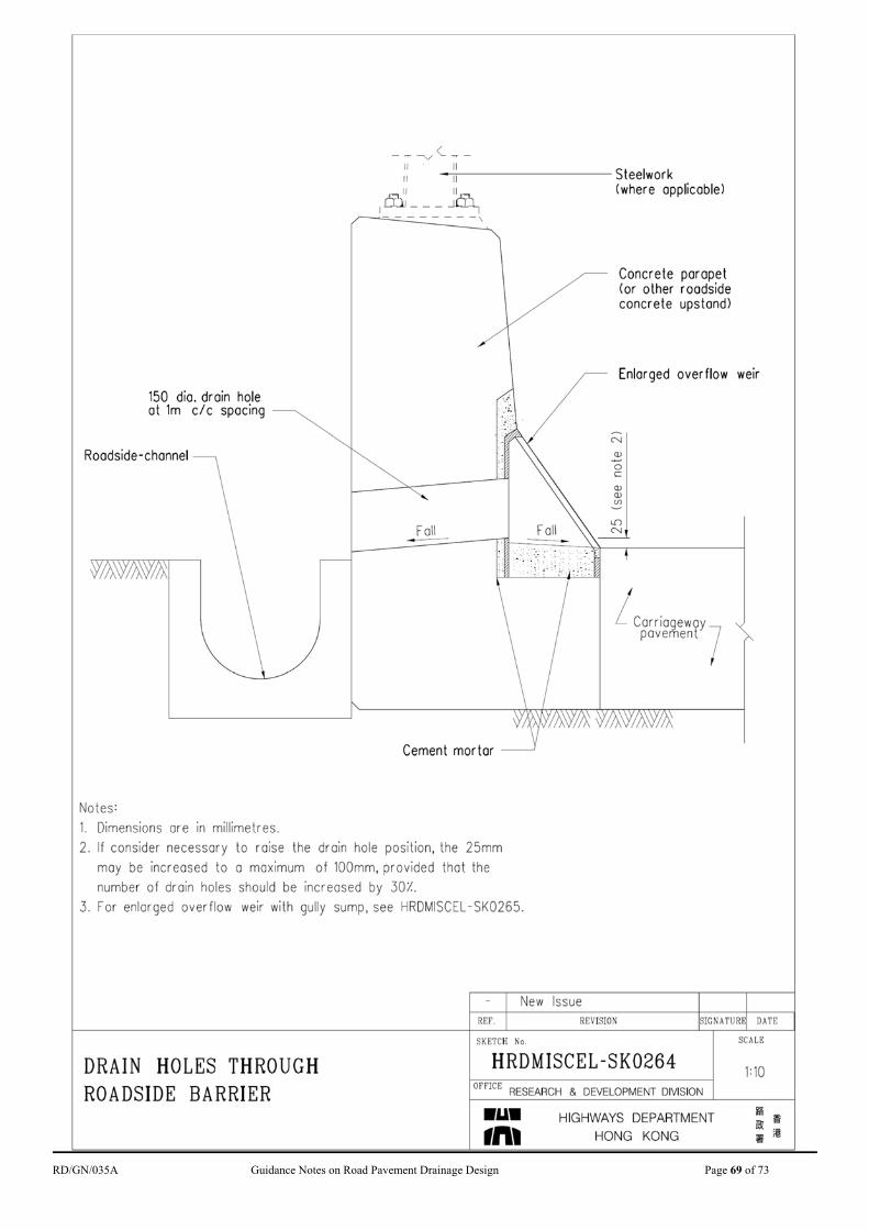
RD/GN/035A Guidance Notes on Road Pavement Drainage Design Page 69 of 73
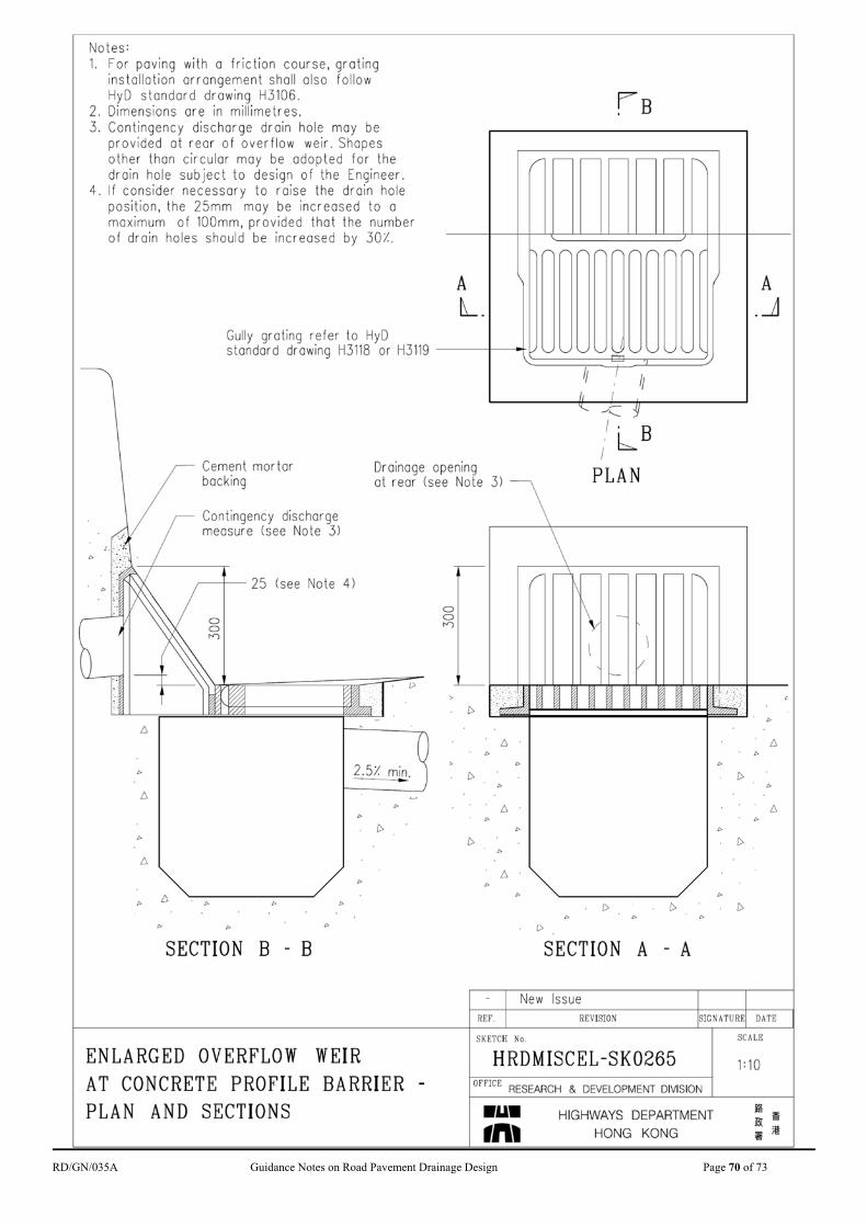
RD/GN/035A Guidance Notes on Road Pavement Drainage Design Page 70 of 73
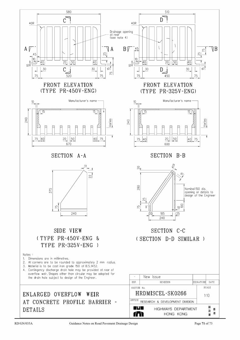
RD/GN/035A Guidance Notes on Road Pavement Drainage Design Page 71 of 73
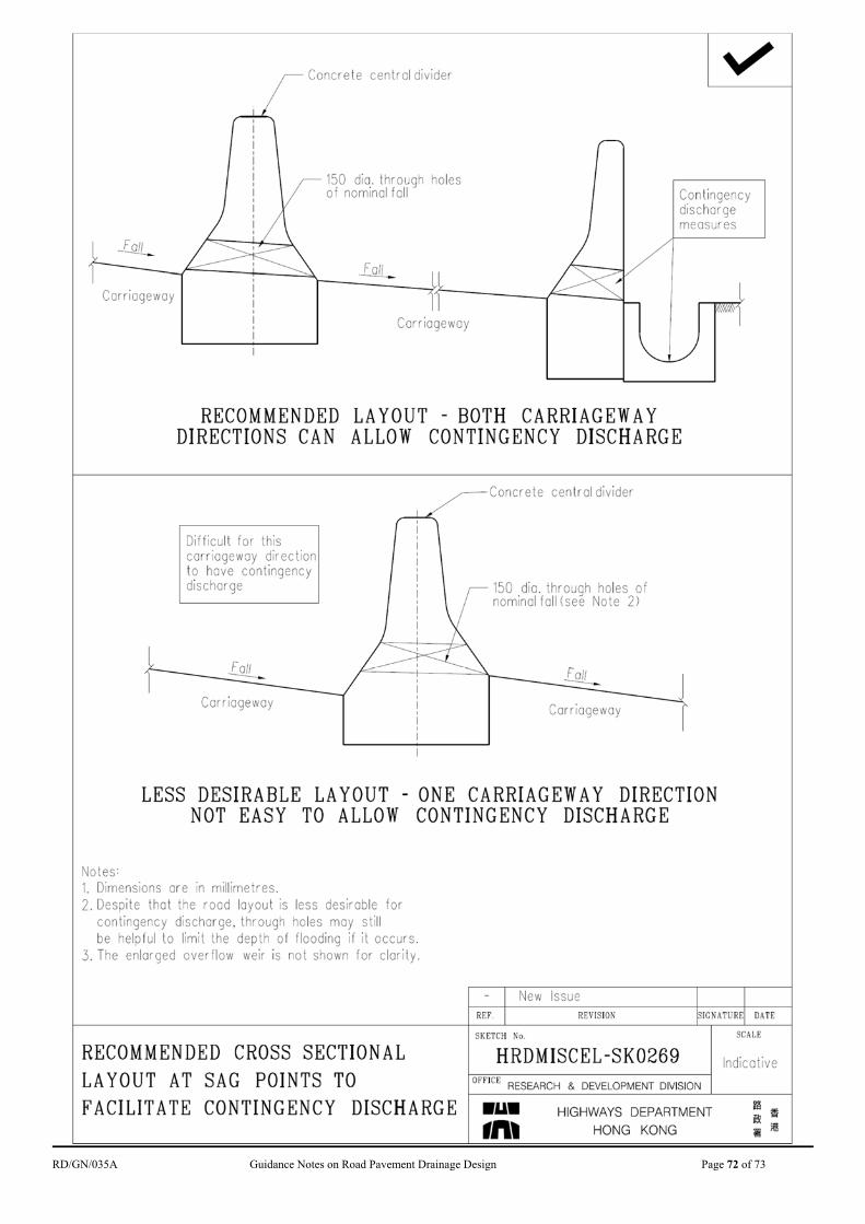
RD/GN/035A Guidance Notes on Road Pavement Drainage Design Page 72 of 73
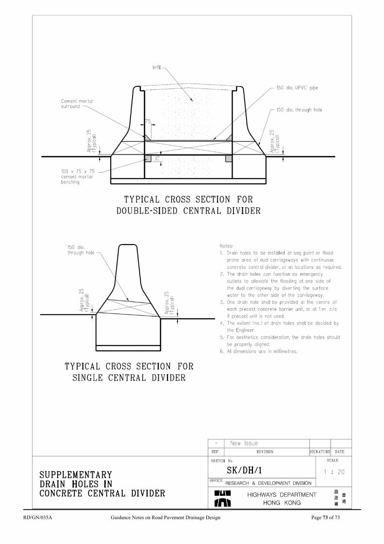
RD/GN/035A Guidance Notes on Road Pavement Drainage Design Page 73 of 73