Guidance for monitoring enclosed landfill gas flares,...
46
Guidance for monitoring enclosed landfill gas flares, LFTGN05
Transcript of Guidance for monitoring enclosed landfill gas flares,...

Guidance for monitoring enclosed landfill gas flares,
LFTGN05
Guidance for monitoring enclosed landfill gas flares, version 4, October 2014 1
Document Owner: National Services/ Knowledge, Strategy and Planning (KSP)
Version History:
Document
Version
Date
Published
Summary of Changes
1.0 Document created
2.0
3.0
4.0 October 2014 Rebrand to NRW
Published by:
Published by: Natural Resources Wales Cambria House 29 Newport Road Cardiff CF24 0TP 0300 065 3000 (Mon-Fri, 8am - 6pm)
www.naturalresourceswales.gov.uk
© Natural Resources Wales All rights reserved. This document may be reproduced with prior permission of Natural Resources Wales

Guidance for monitoring enclosed landfill gas flares, version 4, October 2014 2
Contents
Executive summary ................................................................................................ 3
1 Introduction ......................................................................................................... 5
1.1 Purpose of the guidance .................................................................................... 5
1.2 Document structure ............................................................................................ 5
1.3 Relationship with other guidance ........................................................................ 6
2. Emissions standards and legislation ............................................................... 7
2.1 UK legislation on landfill gas emissions .............................................................. 7
2.2 Air quality standards ........................................................................................... 7
3. Flare monitoring safety ...................................................................................... 9
3.1 Health and safety guidance and regulations ...................................................... 9
4. Standards for monitoring enclosed flares ..................................................... 10
4.1 Emission standards .......................................................................................... 10
4.2 Testing frequency ............................................................................................. 12
4.3 Flow determination ........................................................................................... 13
4.4 Future monitoring options ................................................................................. 13
4.5 Interim position ................................................................................................. 14
4.6 Supplementary inspections .............................................................................. 14
4.7 Relocating and reusing flares ........................................................................... 14
5. Data assessment and reporting ...................................................................... 15
5.1 Data standardisation ........................................................................................ 15
5.2 Representative sampling .................................................................................. 17
5.3 Errors and uncertainty ...................................................................................... 18
5.4 Assessing compliance ...................................................................................... 20
Appendix A: Flare height and dispersion assessment ..................................... 24
Appendix B: Proforma for recording preliminary site visits. ........................... 27
Appendix C: Further information on calculations ............................................. 28
Appendix D: Example flare emission report ...................................................... 35
Appendix E: .......................................................................................................... 36
Technical Guidance Note TGN 024........................................................................ 36
Glossary ................................................................................................................ 39
Guidance for monitoring enclosed landfill gas flares, version 4, October 2014 3
Acronyms .............................................................................................................. 41
References ............................................................................................................ 43
Executive summary This guidance is concerned only with emissions from enclosed flares and
does not consider emissions from other forms of landfill gas combustion. A
separate guidance document is available that discusses the operation and
emissions from landfill gas engines.
This technical guidance document draws upon information from collaborative
research undertaken by Natural Resources Wales and the Biogas
Association.
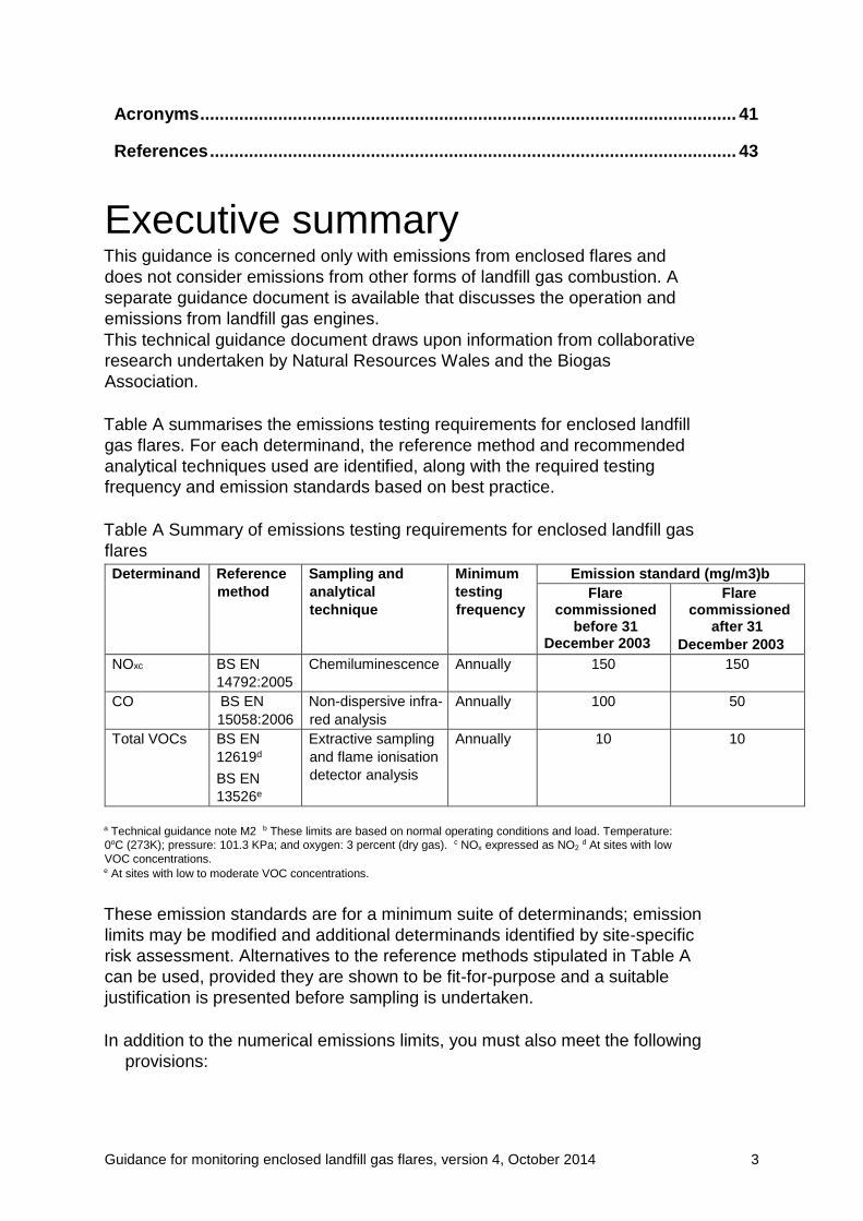
Table A summarises the emissions testing requirements for enclosed landfill
gas flares. For each determinand, the reference method and recommended
analytical techniques used are identified, along with the required testing
frequency and emission standards based on best practice.
Table A Summary of emissions testing requirements for enclosed landfill gas
flares
a Technical guidance note M2 b These limits are based on normal operating conditions and load. Temperature:
0oC (273K); pressure: 101.3 KPa; and oxygen: 3 percent (dry gas). c NOx expressed as NO2 d At sites with low
VOC concentrations. e At sites with low to moderate VOC concentrations.
These emission standards are for a minimum suite of determinands; emission
limits may be modified and additional determinands identified by site-specific
risk assessment. Alternatives to the reference methods stipulated in Table A
can be used, provided they are shown to be fit-for-purpose and a suitable
justification is presented before sampling is undertaken.
In addition to the numerical emissions limits, you must also meet the following
provisions:
Determinand Reference
method
Sampling and
analytical
technique
Minimum
testing
frequency
Emission standard (mg/m3)b
Flare commissioned
before 31 December 2003
Flare commissioned
after 31
December 2003
NOxc BS EN
14792:2005
Chemiluminescence Annually 150 150
CO BS EN
15058:2006
Non-dispersive infra-
red analysis
Annually 100 50
Total VOCs BS EN
12619d
BS EN
13526e
Extractive sampling
and flame ionisation
detector analysis
Annually 10 10

Guidance for monitoring enclosed landfill gas flares, version 4, October 2014 4
• Sample ports must be fitted in accordance with the requirements of
Technical Guidance Document M1or, an alternative method using in situ
probes can be utilised.
• Sampling must be undertaken downstream of the flame. Flare designs
must include sufficient shroud to fully enclose the flame at all times.
• Emissions must not be impeded by cowls or any other fixture on top of the
flare during operation.
• The indicative operational requirements for an enclosed landfill gas flare is
to maintain operational control so as to achieve a minimum temperature of
1,000°C and 0.3 seconds retention time at this temperature across the
likely range of landfill gas composition and throughput.
An equivalent validated set of conditions to give complete combustion are
acceptable providing compliance with the emission standard is
demonstrated. You must monitor the operating temperature.
• You must monitor the flow and composition of the input gas at the flare to
demonstrate consistency with operational requirements and the design
specification of the flare.
Flares that are unable to meet their operational requirements of 1,000°C and
0.3 seconds retention time at this temperature, or have not been maintained,
are unlikely to be monitored in a representative or safe manner. They are
unlikely to meet the emission standard and must be regarded as non-
compliant. Do not undertake emissions testing on these flares until these
operational faults have been rectified.
Due to the practical difficulties of performing representative measurements
inside the combustion chamber of flares and the hazards associated with
such measurement procedures, a new monitoring strategy is required for
sampling emissions from enclosed flares. Several alternatives are under
consideration. Until we have agreed how we will regulate flares, take this
guidance as the best method for the interim.

Guidance for monitoring enclosed landfill gas flares, version 4, October 2014 5
1 Introduction
The 2004 version of this guidance was based on the Research and
Development P1-405, undertaken by netcen.
1.1 Purpose of the guidance
The purpose of this document is to provide a best method approach to
sampling and analysing emissions from enclosed landfill gas flares. We are
reconsidering how we regulate the emissions from enclosed landfill gas
flares. This guidance has been issued in the interim until we decide on a
future approach.
The guidance aims to:
• ensure a consistent and transparent approach to measuring emissions
from enclosed flares;
• ensure that the most appropriate sampling and analytical standards are
followed.
Enclosed (ground) flares are those where the landfill gas is combusted in a
vertical enclosure. Monitoring from such flares is for many reasons, a high
risk activity. Research is ongoing into designs for single and multiple-point
sampling technology.
Section 5.1 sets out the emission standards that enclosed gas flares must
meet.
1.1.1 Elevated/Open flares
It is not possible to accurately or safely sample emissions from open flares,
therefore this document provides no guidance on sampling from open
flares. Do not consider installing an open flare unless it is an emergency.
Open flares are not suitable for standby flares. Elevated flares at
operational and closed sites will be subject to a risk based emissions
review and where identified, a subsequent improvement programme.
1.2 Document structure
The document is divided into six sections:
• Section 1: Introduction including a summary of the purpose of the
guidance
• Section 2: Review of emissions limits
• Section 3: Health and safety issues relating to the measurement of
emissions from landfill flares
• Section 4: Guidance on monitoring flares
• Section 5: Data assessment and reporting
• Section 6: Appendices

Guidance for monitoring enclosed landfill gas flares, version 4, October 2014 6
1.3 Relationship with other guidance
This is one of a series of linked documents that support the overarching
document Guidance on the management of landfill gas (Natural Resources
Wales, 2010a)
The full series comprises:
• Guidance for monitoring trace components in landfill gas
• Guidance on gas treatment technologies for landfill gas engines
• Guidance for monitoring landfill gas surface emissions
• Guidance for monitoring landfill gas engine emissions
We’ve also drawn information from the following documents:
• Sampling requirements for monitoring stack emissions to air from
industrial installations.
Technical Guidance Document (Monitoring) M1
• Monitoring of stack emissions to air. Technical Guidance Note
(Monitoring) M2.
The monitoring procedures and emission standards in this document
supersede those recommended in previous guidance.
In the medium term (pending further development), it may be possible to
augment emissions-based regulation with a system of type
approval/operational monitoring (see Section 4). The UK waste industry is
keen to develop other methods for the future management of emissions from
landfill gas flares. We support such research as it may lead to more cost
effective monitoring of landfill gas flares, content in the knowledge that the
emissions standards are being met.
This document sets out guidance on determining emissions from enclosed
landfill gas flares.
Enclosed (ground) flares are those where the landfill gas is combusted in a
vertical enclosure. Monitoring from such flares is for many reasons, a high risk
activity. Research is in progress into designs for single and multiple-point
sampling technology.
Guidance for monitoring enclosed landfill gas flares, version 4, October 2014 7
2. Emissions standards and
legislation
2.1 UK legislation on landfill gas emissions
The principal legislation covering landfills in Europe is the Landfill Directive
(Council of the European Union, 1999), which provides for measures and
procedures to prevent or reduce as far as possible the negative environmental
effects of landfilling waste.
Landfills and their operation are now regulated under a single regime that
complies with both the Landfill Directive and the Integrated Pollution
Prevention and Control (IPPC) Directive. In the UK, this is through the
Environmental Permitting Regulations (EPR) 2007.
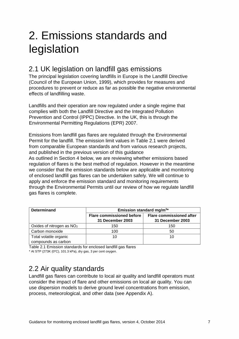
Emissions from landfill gas flares are regulated through the Environmental
Permit for the landfill. The emission limit values in Table 2.1 were derived
from comparable European standards and from various research projects,
and published in the previous version of this guidance
As outlined in Section 4 below, we are reviewing whether emissions based
regulation of flares is the best method of regulation. However in the meantime
we consider that the emission standards below are applicable and monitoring
of enclosed landfill gas flares can be undertaken safely. We will continue to
apply and enforce the emission standard and monitoring requirements
through the Environmental Permits until our review of how we regulate landfill
gas flares is complete.
Table 2.1 Emission standards for enclosed landfill gas flares * At STP (273K (0oC), 101.3 kPa), dry gas, 3 per cent oxygen.
2.2 Air quality standards
Landfill gas flares can contribute to local air quality and landfill operators must
consider the impact of flare and other emissions on local air quality. You can
use dispersion models to derive ground level concentrations from emission,
process, meteorological, and other data (see Appendix A).
Determinand Emission standard mg/m3*
Flare commissioned before
31 December 2003
Flare commissioned after
31 December 2003
Oxides of nitrogen as NO2 150 150
Carbon monoxide 100 50
Total volatile organic
compounds as carbon
10 10
Guidance for monitoring enclosed landfill gas flares, version 4, October 2014 8
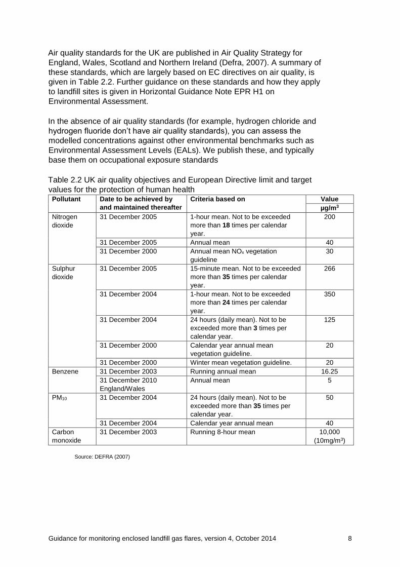
Air quality standards for the UK are published in Air Quality Strategy for
England, Wales, Scotland and Northern Ireland (Defra, 2007). A summary of
these standards, which are largely based on EC directives on air quality, is
given in Table 2.2. Further guidance on these standards and how they apply
to landfill sites is given in Horizontal Guidance Note EPR H1 on
Environmental Assessment.
In the absence of air quality standards (for example, hydrogen chloride and
hydrogen fluoride don’t have air quality standards), you can assess the
modelled concentrations against other environmental benchmarks such as
Environmental Assessment Levels (EALs). We publish these, and typically
base them on occupational exposure standards
Table 2.2 UK air quality objectives and European Directive limit and target
values for the protection of human health Pollutant Date to be achieved by
and maintained thereafter
Criteria based on Value
µg/m3
Nitrogen
dioxide
31 December 2005 1-hour mean. Not to be exceeded
more than 18 times per calendar
year.
200
31 December 2005 Annual mean 40
31 December 2000 Annual mean NOx vegetation
guideline
30
Sulphur
dioxide
31 December 2005 15-minute mean. Not to be exceeded
more than 35 times per calendar
year.
266
31 December 2004 1-hour mean. Not to be exceeded
more than 24 times per calendar
year.
350
31 December 2004 24 hours (daily mean). Not to be
exceeded more than 3 times per
calendar year.
125
31 December 2000 Calendar year annual mean
vegetation guideline.
20
31 December 2000 Winter mean vegetation guideline. 20
Benzene 31 December 2003 Running annual mean 16.25
31 December 2010
England/Wales
Annual mean 5
PM10 31 December 2004 24 hours (daily mean). Not to be
exceeded more than 35 times per
calendar year.
50
31 December 2004 Calendar year annual mean 40
Carbon
monoxide
31 December 2003 Running 8-hour mean 10,000
(10mg/m3)
Source: DEFRA (2007)

Guidance for monitoring enclosed landfill gas flares, version 4, October 2014 9
3. Flare monitoring safety
3.1 Health and safety guidance and regulations
Neither SEPA nor Natural Resources Wales regulates health and safety at
work. Discuss any issues or concerns you have with the Health and Safety
Executive (HSE).
The Health and Safety at Work Regulations 1974, and similar legislation
places a duty on employers to have a safety policy and to carry out risk
assessments for any work programme. Any work you carry out to MCERTS
(Natural Resources Wales, 2008a) standards also requires you to produce a
risk assessment. Technical Guidance Note M1 contains detailed guidance on
assessing safety requirements at a test site.
Also consider the guidance in our Technical Guidance Note M2. This provides
more detailed guidance on safely monitoring emissions from stacks.
The Source Testing Association (STA) also provides guidelines such as the
general hazards and potential risks associated with emissions testing (STA,
2001a) and example risk assessments for stack sampling operations (STA,
2000).
Documents from the STA are reviewed and revised from time to time and the
reader should check the STA website for the most up to date information.
Guidance for monitoring enclosed landfill gas flares, version 4, October 2014 10
4. Standards for monitoring
enclosed flares
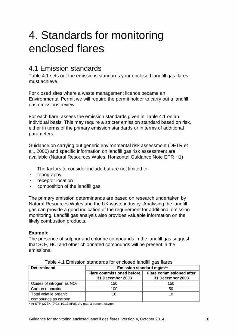
4.1 Emission standards
Table 4.1 sets out the emissions standards your enclosed landfill gas flares
must achieve.
For closed sites where a waste management licence became an
Environmental Permit we will require the permit holder to carry out a landfill
gas emissions review.
For each flare, assess the emission standards given in Table 4.1 on an
individual basis. This may require a stricter emission standard based on risk,
either in terms of the primary emission standards or in terms of additional
parameters.
Guidance on carrying out generic environmental risk assessment (DETR et
al., 2000) and specific information on landfill gas risk assessment are
available (Natural Resources Wales; Horizontal Guidance Note EPR H1)
The factors to consider include but are not limited to:
• topography
• receptor location
• composition of the landfill gas.
The primary emission determinands are based on research undertaken by
Natural Resources Wales and the UK waste industry. Analysing the landfill
gas can provide a good indication of the requirement for additional emission
monitoring. Landfill gas analysis also provides valuable information on the
likely combustion products.
Example
The presence of sulphur and chlorine compounds in the landfill gas suggest
that SO2, HCl and other chlorinated compounds will be present in the
emissions.
Table 4.1 Emission standards for enclosed landfill gas flares Determinand Emission standard mg/m3*
Flare commissioned before
31 December 2003
Flare commissioned after
31 December 2003
Oxides of nitrogen as NO2 150 150
Carbon monoxide 100 50
Total volatile organic
compounds as carbon
10 10
* At STP (273K (0oC), 101.3 kPa), dry gas, 3 percent oxygen.

Guidance for monitoring enclosed landfill gas flares, version 4, October 2014 11
Commission all new flares to meet the post 31 December 2003 standards.
In addition to the numerical emission standards, you must also meet the
following provisions:
• Sample ports must be fitted in accordance within the requirements of
Technical Guidance Note M1 or, alternatively, in situ sample probes.
• Undertake sampling after combustion is completed (that is, downstream
of the flame). Flare designs must include sufficient shroud to fully enclose
the flame at all times.
• Emissions must not be impeded by cowls or any other fixture on top of the
flare during operation.
• Operational control must be able to achieve a minimum of 1,000°C and
0.3 seconds retention time at this temperature (or an equivalent
validated set of conditions).
• Monitor the flow and composition of the input gas regularly to demonstrate
consistency with operational requirements and the flare’s design
specification.
Monitoring
You must monitor the flame temperature to demonstrate the consistent
performance output of the enclosed flare.
You must monitor the inlet gas to demonstrate that:
• the enclosed flare is operating within design limits for gas flow and gas
composition;
• the performance of the flare at the time of the periodic emissions
monitoring is representative of normal operation.
In order to monitor input gas, install suitable sampling points for flow and gas
composition in the pipework at a representative location close to the flare.
The minimum monitoring requirement for inlet gas composition is methane
and oxygen.
The frequency and degree of automation your monitoring will require will
depend on the operational circumstances. Where a flare is operating on a
stable, consistent gas field, a small number of readings per day will be
sufficient to demonstrate performance. Where a flare is handling gas from a
large field with multiple manifolds, you may require frequent readings to
provide a signal trace.
Log monitoring data associated with the inlet gas (such as, methane, oxygen
and flow rate) and the output (for example, temperature) of the enclosed
flare.
We recommend that monitoring data is transferred by telemetry to those
responsible for operational control. The need for telemetry will depend on
the site-specific risks that may result from short-term deviation from
Guidance for monitoring enclosed landfill gas flares, version 4, October 2014 12
operational standards. Factors that will influence the need for telemetry
include:
• the proximity to receptors;
• size of the enclosed flare;
• whether the flare is associated with an engine installation.
4.1.1 Landfill gas emission review
An emissions review is based on developing a risk screening/conceptual
model of gas management for the site and will include providing flaring.
The emissions review must contain, but is not limited to:
• site history
• conceptual model including cap/liner details
• gas control system including drawings identifying infrastructure
• assessment of risk
• conclusion
• improvement programme schedule if required including time line.
Unacceptable site specific risks
Where the review identifies unacceptable site-specific risks from landfill gas,
we will require an emissions improvement programme that incorporates the
appropriate best practice contained within this guidance and industry specific
codes of practice. You must carry out an emissions review and improvement
programme according to site-specific risk and complete this as soon as is
reasonably practical.
4.2 Testing frequency
Derive the frequency of emission testing required from a flare from an
individual site environmental risk assessment. Once you have established a
consistent emissions profile, you may reduce the monitoring frequency to the
minimum frequency, in agreement with us. Test annually as a minimum.
Where an enclosed flare is used as standby equipment to back up landfill gas
engines then you do not need to carry out emissions testing unless the flare
has been operational for more than 10 per cent of a year (876 hours).
Consider test work to verify combustion temperature and residence time when
commissioning a new flare.
In addition to servicing, you must carry out combustion spot checks to
demonstrate the unit is functioning as designed. Also consider installing
permanent sample systems to enable this to be undertaken easily at ground
level without the need to fit platforms. Basic instrumentation exists on most
flares (for example, to indicate the combustion chamber temperature) and
spot checks using hand-held systems allow combustion gases such as CO,
CO2 and O2 to be monitored easily.
Guidance for monitoring enclosed landfill gas flares, version 4, October 2014 13
4.3 Flow determination
Carry out a theoretical determination of the exhaust flow rate based on the
flow and composition of the incoming gas. Use this in combination with the
manufacturer’s specification to determine the volumetric flow rate for your
flare. Appendix C details how to carry out a theoretical flow determination.
Remember to correct the resulting flow for moisture and oxygen content using
the correction factors in Appendix C.
4.4 Future monitoring options
Due to the practical difficulties of performing representative measurements
inside the combustion chamber of flares and the hazards associated with
such measurement procedures, a new monitoring strategy is required for
sampling emissions from enclosed flares. Several alternatives are under
consideration.
One possibility could be the adoption of a type-approval system for flares.
Under such a system, appropriate flares would be certified capable of
complying with the emissions standards specified in Table 4.1. This approach
avoids as far as possible any working at height or hot work, thereby
eliminating most of the risks associated with sampling emissions from high
temperature flares.
Records
We would also require a record of annual maintenance to the manufacturer’s
specifications to demonstrate efficient operation in lieu of any monitoring of
the flare emissions. This approach avoids as far as is possible any working at
height or hot work, thereby eliminating most of the risks associated with
sampling emissions from high temperature flares.
Alternative approaches
An alternative approach could be based on current research into the design
and installation of single point and multiple point sampling probes. This
research is looking at technologies capable surviving the harsh conditions
within flares. Such technologies may form the basis of future guidance. This
envisaged approach relies on a permanent sampling system installed on each
flare so a sample can be collected from ground level. The gas conditioning
required between sampling and analysis would be partly performed by the
permanent installation, and partly by mobile laboratory attached to the
sampling line. This method will also avoid most of the risks associated with sampling high
temperature flares.
Other approaches under consideration are a commissioning trial whereby an
envelope of operating parameters would be established across the maximum
and minimum rated capacity that demonstrates the flare meets the emission
Guidance for monitoring enclosed landfill gas flares, version 4, October 2014 14
standards. Monitoring of these operating parameters, such as flow and
temperature, would demonstrate the flare was within the operational
envelope.
4.5 Interim position
Pending the development of an effective alternative monitoring system you
are still required to conduct emissions tests on flares that are operational for
more than 10 per cent of a year (876 hours). The Source Testing Association
has produced a Technical Guidance Note (TGN No. 24) on how to carry out
emissions tests from flares safely. This is available from their website and is
reproduced in Appendix E.
Follow this guidance where your permit requires you to test the flare.
4.6 Supplementary inspections
Your management systems and gas management plan must include a six
monthly inspection of your flare and its immediate ancillary infrastructure to
ensure operation in accordance with the manufacturer’s specifications. This
inspection must be carried out by a suitably qualified person.
Ancillary infrastructure includes:
• the booster and motor;
• mechanical systems (such as joints and valves);
• safety systems (flame arrestors and slam shut valves);
• electrical systems;
• instrumentation;
• gas conditioning vessels.
Where possible, six monthly inspections should observe the flare’s operation
at both its maximum rated capacity and its minimum rated capacity (normally
a 5:1 or 10:1 turndown).
Ensure you record any faults and defects that occur during normal operation.
You must rectify all faults as soon as is practical.
Emergency flares
Emergency flares and their supporting infrastructure must undergo an annual
inspection to ensure they are able to operate efficiently when required.
You must retain the details and records of your inspections and any
modifications or repairs and make them available to us if we ask to see them.
4.7 Relocating and reusing flares
There are currently two separate enclosed flares emissions standards
depending on when a flare was first commissioned. Relocating flares
Guidance for monitoring enclosed landfill gas flares, version 4, October 2014 15
commissioned under earlier standards should be considered on a site-specific
risk assessed basis following Natural Resources Wales Horizontal Guidance
Note EPR H1.
Do not relocate open flares unless for emergency purposes and then only for
a limited time until you can replace them with a temporary enclosed flare.
5. Data assessment and reporting
5.1 Data standardisation
5.1.1 Reference conditions
All emission concentrations determined at enclosed landfill gas flares should
be standardised to reference conditions of:
• mass concentration;
• standard temperature and pressure (STP), that is, 273K (0°C) and 101.3
kPa (1 atmosphere);
• 3 per cent v/v oxygen;
• dry gas. Nitrogen oxides should be expressed as NO2 and VOCs as
carbon. Details of the calculations used to standardise emission data are
given in Appendix D, but the key calculations are described below.
You must report all landfill gas flare emissions as concentrations and mass
emission rates, together with supporting information. To convert the measured
emissions concentrations to the reference conditions, apply a series of
correction factors to the data. Basic details about these correction factors are
provided below and more detail is given in Technical Guidance Note M2.
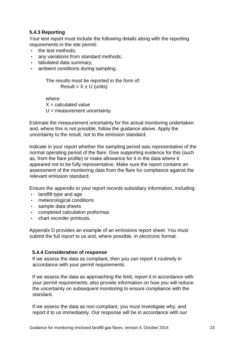
5.1.2 Conversion from volume concentration to mass concentration
Many emission measurements using instrumental techniques report emission
data as volume concentrations such as parts per million (ppm). These can be
converted to mg/m3 at STP using the following formula:
mg/m 3= ppm× Mw
22.4
where: Mw = molecular weight (for example, NO2=46 and CO=28).
5.1.3 Oxygen correction
Standardising emission concentrations to a fixed oxygen concentration
removes dilution effects caused by different excess air levels in the flare. This
allows a true comparison of emission concentrations.

Guidance for monitoring enclosed landfill gas flares, version 4, October 2014 16
The relationship between the measured oxygen and measured emission
species concentration is not linear as oxygen from air is added or removed.
The equation for the concentration at reference conditions can be written as:
Cr = Cm x (20.9-(O2)r)
(20.9 - (O2)m)
where:
Cr = emission concentration at reference conditions
Cm = measured emission
concentration
(O2)r = reference oxygen concentration
(percentage v/v dry) (O2)m = measured
oxygen concentration (percentage v/v
dry).
As the reference oxygen condition for landfill gas flares is 3 per cent,
this equation becomes:
Cr = Cm x 17.9
(20.9 - (O2)m)
If you use oxygen enhancement, you can apply a modified form of the
equation (see Appendix D).
5.1.4 Moisture correction
Standardised concentrations are expressed in the dry condition and, although
some emission concentrations are measured dry, other measurements are
undertaken on ‘wet’ gas. The moisture content of such gas is usually
expressed in volume/volume (v/v) terms.
For example, the percentage volume of water vapour is the total wet gas
volume.
Correct emission concentrations to the standardised dry condition using the
following formula:
Cdry = Cwet x 100/(100 – %H2O)
where:
Cdry = concentration of emission at dry condition
Cwet = concentration of emission at wet condition
%H2O = moisture content of exhaust gas (percentage v/v wet).

Guidance for monitoring enclosed landfill gas flares, version 4, October 2014 17
5.1.5 Emission rate
You determine the emission rate from the flue gas flow rate and emission
concentration. It is essential you express the emission concentration and flow
rate at the same temperature, pressure, oxygen and moisture content.
Due to the high temperature and low velocities within an enclosed flare, direct
flow measurements may not be practical at many sites. However, you can
determine flow from the combustion calculation and landfill gas analysis, for
example, using calculations in USEPA Method 19 (USEPA, online 1).
5.2 Representative sampling
The four recognised types of monitoring used to measure emissions are:
• continuous – a complete series of measurements covering all operating
conditions;
• periodic – intermittent measurements covering different conditions of normal
operation;
• group – a number of measurements made under the same operating
conditions;
• individual – lone measurements, which are not part of a group.
The emissions standards presented in this guidance are derived from a group
of measurements collected at a range of landfills and from a number of
different flare designs representative of normal operations in the UK. The
measurements were generated as an average over one-hour test periods.
Periodic measurements
The guidance on monitoring requires periodic measurement to determine the
emissions profile of an enclosed landfill flare. The protocol involves sampling
over an hour but, inevitably, this only covers a small period in the emissions
from the flare. Consequently, it’s necessary to assume the periodic
measurement is representative of operation outside the monitoring periods.
Increased confidence in this assumption can be provided by developing an
emissions profile for the flare. This profile may be built up over time and by
making targeted measurements under a range of different conditions in
normal operation. In addition, surrogate determinands and operational
information (such as, maintenance logs and gas flow) can be used to confirm
consistent operation of the flare.
If the operational information during the monitoring period differs substantially
from that recorded for the preceding months, the sampling is unrepresentative
of the earlier operation. It will only be representative of future operations if the
operating profile does not change further.
Ensure the quality and consistency of the representative samples by using the
methods and techniques outlined in this guidance.

Guidance for monitoring enclosed landfill gas flares, version 4, October 2014 18
5.3 Errors and uncertainty
Measurements of flow and chemical emissions in enclosed flares do not meet
the MCERTS standard. Therefore, when assessing compliance against the
emission standards for flares, you must take account of the representative
nature and reliability of the measured values. The uncertainty arising from
unrepresentative sampling and the errors from measurement uncertainty are
considered below.
5.3.1 Measurement uncertainty
A number of different uncertainties (such as, uncertainty from sampling
position, sampling equipment, analytical equipment and chemical/physical
uncertainty) have to be combined to assess the overall uncertainty of
measurement.
You can calculate the overall measurement uncertainty by:
• defining the steps of a measurement;
• identifying the sources of uncertainty associated with these steps; •
quantifying the respective uncertainties;
• combining these uncertainties.
Combine the component uncertainties using the following formula, which
involves taking the square root of the sum of the squares of the individual
uncertainties.
Ucombined = (u u u12 + + +22 32 .......un2)
You must determine each measurement and associated uncertainty within a
known confidence limit, that is, you’re confident the interval chosen does
contain the real value. For emission measurements associated with landfill
gas flares, the confidence level is 95 per cent.
Wherever possible, you should report and use the specific uncertainty in a set
of monitoring measurements in your assessment. A method for calculating
uncertainty is given in Guide to the expression of uncertainty in
measurements (ISO, 1995). However, where you can’t reasonably estimate
an uncertainty, use the guidance below to derive typical acceptable values.
Errors and uncertainty greater than those given below generally indicate
unsatisfactory monitoring.
Measurement uncertainty
The Source Testing Association (STA) has assessed the uncertainty
associated with particular analytical methods used in monitoring combustion
(STA, 2001b). Based on a review of literature and enquiries made to stack
sampling contractors, they concluded the uncertainty associated with most
analytical methods for measuring NOx and carbon monoxide was 12 per cent

Guidance for monitoring enclosed landfill gas flares, version 4, October 2014 19
(at the 95 per cent level of confidence). However, the method of NOx analysis
using an electrochemical cell had an uncertainty of 20 per cent and methods
of determining speciated VOCs using adsorptionthermal desorption had an
uncertainty of 25 per cent. These uncertainties take account of:
• limitations in the method, such as, sampling, analysis,
instruments, interferences;
• variations due to human factors between different, but
competent, monitoring teams.
Where analytical methods are in accordance with a recognised measurement
standard, the measurement uncertainty is better understood. Table 5.2 gives
the quoted uncertainty for the methods referenced in this guidance.
The uncertainties quoted in Table 5.2 only apply when measurement complies
fully with the standard method. However, the design and operation of
enclosed flares means it’s not usually possible to undertake fully compliant
tests.
For example, measuring NOx and CO using ISO 10849 and ISO 12039,
respectively, requires a species variation across the sample plane of less than
±15 per cent to justify a single point sampling campaign. Otherwise you must
adopt a multi-point sampling procedure at the points described in ISO 9096
(ISO, 2003). Where you use this multi-point sampling, there will be additional
uncertainties relating to the multi-point procedure.
Table 5.2 Quoted uncertainty for reference methods
Determinand Reference Quoted uncertainty
Nitrogen oxides BS EN 14792: 2005 <10 percent of full scale deflection
Carbon monoxide BS EN 15058: 2006 <10 percent of full scale deflection
Total volatile organic
compounds
BS EN 12619 :1999 BS
EN 13526 : 2002
0.28-0.42 mg/m3 for a concentration
range of <1 to 15 mg/m3
In addition, the measurement standard also requires five hydraulic diameters
of straight shroud before the sampling plane and five hydraulic diameters from
the shroud exit. This is often not possible; consequently, your measurements
will have different uncertainty from those quoted in the measurement
standards. You will therefore need to calculate an overall measurement
uncertainty.
Nevertheless, it is important you attempt to improve the uncertainty by taking
samples further from the shroud exit. However, don’t undermine the primary
need to sample above the flame. Measurement uncertainty is unacceptable if
the sampling plane is less than a metre below the shroud exit to avoid
sampling within the flame. For this reason, you must install flares with the
maximum height of post-combustion shroud consistent with planning
requirements.

Guidance for monitoring enclosed landfill gas flares, version 4, October 2014 20
Large Combustion Plant and the Waste Incineration Directives
The Large Combustion Plant and the Waste Incineration Directives (Council of
the European Union, 2002 and 2001) cover the monitoring of several relevant
combustion products. They quote measurement uncertainties at the daily
emission limit value level. The directives state the values of the 95 per cent
confidence intervals of a single measured result must not exceed the
percentages of the emission limit values quoted in Table 5.3.
Table 5.3 Measurement uncertainties quoted for selected determinands in Large
Combustion Plant and Waste Incineration directives
Component Measurement uncertainty (percent)
Hydrogen chloride 40
Sulphur dioxide 20
Nitrogen oxides 20
Carbon monoxide 10
Table 5.4 Typical measurement uncertainty for methods used in monitoring
emissions from enclosed flares
Determinand Method description Typical uncertainty
(percent)
Nitrogen oxides Extractive NDIR and chemiluminescence (BS EN 14792: 2005)
20
Carbon monoxide Extractive NDIR (BS EN 15058:
2006)
12
Total volatile organic
compounds
Flame ionisation detection BS
EN 12619 : 2002
25
Regard the values in Table 5.3 as ‘target uncertainties’ for monitoring flare emissions.
Table 5.4 shows the uncertainty you can expect in measurements by the recommended
methods.
These values are based on:
• the degree of the uncertainty in the standard methods;
• guidance from relevant directives and the extent of deviation needed
when applying these to flares;
• results obtained from Natural Resources Wales R&D on monitoring
(Natural Resources Wales R&D Report CWM 142/96A 1997).
5.4 Assessing compliance
The way we assess compliance of the measured values against the emissions
standards can be divided into four stages:
• confirmation of evidence
• determination of compliance with emission standard
• reporting
• consideration of response.
As the operator, you will normally be responsible for the first three stages,
while we will assess your report and consider our response.

Guidance for monitoring enclosed landfill gas flares, version 4, October 2014 21
5.4.1 Confirmation of evidence
The quality and representative nature of the measurements have to be
addressed in order to ensure that the data are within the scope covered by
the limit value.
Questions you need to address include:
• Is the data of adequate quality?
• Have the correct monitoring methods been used?
• Have the monitoring methods been used correctly?
• Have there been any deviations from the recommended
monitoring methods? If so, are these justified and what effect
have they had on the quality of measurement?
• Does the emission profile indicate that the sample was
representative?
If you can’t answer any of these points satisfactorily, your data may be
inadequate for a full compliance assessment. Further action may be required
to achieve representative monitoring.
The reported uncertainty in measurements won’t take into account the
variability of the emissions at times between the periodic monitoring. The
uncertainty arising from unrepresentative sampling periods will be site-specific
and will change during the operational period at the site.
Where you can deduce this from the flare’s operating profile that is, variations
in flow, composition and temperature, you should state this and add the
additional uncertainty to the measurement uncertainty. Where you can’t
deduce this, we will assume that the total uncertainty, including that related to
the representative nature of the measurements, will not exceed the values
given in Table 5.5. If your calculated total uncertainty exceeds these values, it
generally indicates unsatisfactory monitoring or erratic flare performance.
5.4.2 Determination of compliance with the emission standard
All monitoring data is subject to error and uncertainty. Any assessment of
compliance must take account of this. Our fundamental principle is that the
emission standard itself is fixed and any allowance for uncertainty is
associated with the monitoring data. Our compliance assessment of
emissions from landfill gas flares is subject to the same general principles we
apply to the regulation of other emissions. These are covered in our
Compliance Classification Scheme guidance.
The values in Table 5.5 are the maximum uncertainty for the associated tests.
Assess compliance using the value of uncertainty in table 5.5 or that which is
quoted in the report, whichever is the lower.
Table 5.5 Apply maximum values for measurement uncertainty when
assessing compliance of emissions from enclosed flares.
Guidance for monitoring enclosed landfill gas flares, version 4, October 2014 22
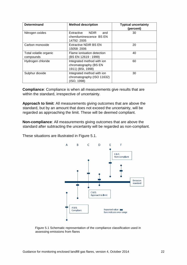
Determinand Method description Typical uncertainty
(percent)
Nitrogen oxides Extractive NDIR and
chemiluminescence BS EN
14792: 2005
30
Carbon monoxide Extractive NDIR BS EN
15058: 2006
20
Total volatile organic
compounds
Flame ionisation detection
(BS EN 12619 : 1999)
40
Hydrogen chloride Integrated method with ion
chromatography (BS EN
1911) (BSI, 1998)
60
Sulphur dioxide Integrated method with ion
chromatography (ISO 11632)
(ISO, 1998)
30
Compliance: Compliance is when all measurements give results that are
within the standard, irrespective of uncertainty.
Approach to limit: All measurements giving outcomes that are above the
standard, but by an amount that does not exceed the uncertainty, will be
regarded as approaching the limit. These will be deemed compliant.
Non-compliance: All measurements giving outcomes that are above the
standard after subtracting the uncertainty will be regarded as non-compliant.
These situations are illustrated in Figure 5.1.
Figure 5.1 Schematic representation of the compliance classification used in
assessing emissions from flares
Guidance for monitoring enclosed landfill gas flares, version 4, October 2014 23
5.4.3 Reporting
Your test report must include the following details along with the reporting
requirements in the site permit:
• the test methods;
• any variations from standard methods;
• tabulated data summary;
• ambient conditions during sampling.
The results must be reported in the form of:
Result = X ± U (units)
where:
X = calculated value
U = measurement uncertainty.
Estimate the measurement uncertainty for the actual monitoring undertaken
and, where this is not possible, follow the guidance above. Apply the
uncertainty to the result, not to the emission standard.
Indicate in your report whether the sampling period was representative of the
normal operating period of the flare. Give supporting evidence for this (such
as, from the flare profile) or make allowance for it in the data where it
appeared not to be fully representative. Make sure the report contains an
assessment of the monitoring data from the flare for compliance against the
relevant emission standard.
Ensure the appendix to your report records subsidiary information, including:
• landfill type and age
• meteorological conditions
• sample data sheets
• completed calculation proformas
• chart recorder printouts.
Appendix D provides an example of an emissions report sheet. You must
submit the full report to us and, where possible, in electronic format.
5.4.4 Consideration of response
If we assess the data as compliant, then you can report it routinely in
accordance with your permit requirements.
If we assess the data as approaching the limit, report it in accordance with
your permit requirements; also provide information on how you will reduce
the uncertainty on subsequent monitoring to ensure compliance with the
standard.
If we assess the data as non-compliant, you must investigate why, and
report it to us immediately. Our response will be in accordance with our
Guidance for monitoring enclosed landfill gas flares, version 4, October 2014 24
Compliance Common Classification Scheme. The urgency of your
investigation will be determined by the degree of non-compliance and the
risk associated with the emission.
Example
A marginally non-compliant case (that is, up to 25 per cent over the standard
after allowing for uncertainty) that is not close to a sensitive receptor would
normally require a report within seven days. Alternatively, a grossly non-
compliant case close to a sensitive receptor requires immediate investigation
and a report within 24 hours. The action we take will be consistent with our
enforcement and prosecution policy.
Appendix A: Flare height and
dispersion assessment
General This appendix provides a short overview of the dispersion and impact of
enclosed flare stack emissions management. It includes elements of the
design of discharge stacks and dispersion modelling applied to assess
impacts.
In theory, a flare stack elevates the plume so the initial dispersion of the
plume is at a greater altitude. By the time the plume has returned to ground
level, emission concentrations should have reduced to acceptable levels. A
flare stack should generally be high enough to ensure this occurs. ‘Local’ may
mean anything from 10 metres to 1 kilometre. At large distances from a flare
stack (100 stack heights), the effect of stack height on dispersion is no longer
distinguishable (unless the plume has penetrated the boundary layer). In
addition, the effects of single sources start to become indistinguishable at
such distances from the background produced by other sources.
In carrying out its statutory duty, the local planning authority must consider
other factors (such as, visual impact and noise) and thus may impose a
restriction on flare stack height and location.
Adjustment of flare height
The following impacts can be reduced by adjusting the height of the flare
stack:
• odours
• effects of ambient concentrations
• deposition of emissions – mainly heavy metals, acidic materials
or long-lived chemicals (for example PCDDs)
• noise
• nuisance dusts
Guidance for monitoring enclosed landfill gas flares, version 4, October 2014 25
• visibility/obscuration.
The importance of emission exposure times
Where emissions are associated with a range of exposure limits with different
exposure times (as, for example, with SOx and NOx), it is usually the short-
term exposure which is critical. This is mainly because short-term exposures
are not repeated very often at the same point; so although shortterm
concentrations may be high, the effect on longer-term averages is usually low
in relation to their respective limit concentrations. With longer-term averages,
the background concentrations of common emissions become more important
and may make a larger contribution to overall levels than that from a single
local source.
Determining the appropriate height of the flare
You need the following information to calculate a flare stack height:
• details of the emission rate;
• details of the site and its surroundings;
• identification of the critical emissions including rates and typical
background concentrations;
• a dispersion model;
• any controls or limitations imposed by guidance notes, and so on;
• meteorological conditions.
Typically, landfill gas flares have low emission velocity which can result in
downwash being a common problem, regardless of the high temperature
(hence thermal buoyancy). A standard method of determining stack heights
for broader discharges is available (HMIP, 1993).
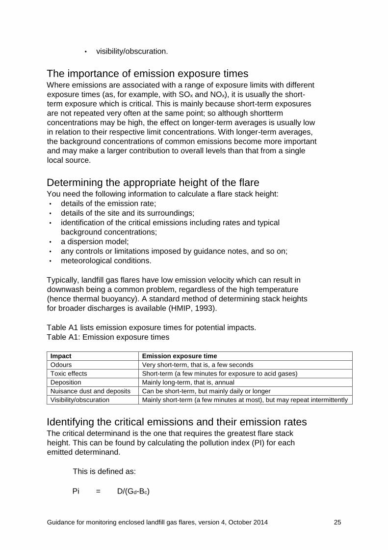
Table A1 lists emission exposure times for potential impacts.
Table A1: Emission exposure times
Impact Emission exposure time
Odours Very short-term, that is, a few seconds
Toxic effects Short-term (a few minutes for exposure to acid gases)
Deposition Mainly long-term, that is, annual
Nuisance dust and deposits Can be short-term, but mainly daily or longer
Visibility/obscuration Mainly short-term (a few minutes at most), but may repeat intermittently
Identifying the critical emissions and their emission rates
The critical determinand is the one that requires the greatest flare stack
height. This can be found by calculating the pollution index (PI) for each
emitted determinand.
This is defined as:
Pi = D/(Gd-Bc)
Guidance for monitoring enclosed landfill gas flares, version 4, October 2014 26
where:
D = discharge rate of the
determinand Gd =
guideline concentration of
the determinand Bc =
background concentration
of the emission.
Standard stack height calculation methods are used to determine these
parameters, which can vary from simple formulae to complex computer-based
methods.
Dispersion modelling There are many dispersion models covering a whole spectrum of complexity
and reliability.
However, there are limitations in their use because:
• dispersion models are approximations to a very complex process;
• dispersion itself is a stochastic process, so that there is never a single,
accurate, answer to a dispersion calculation.
For enclosed flare stack height calculations and hence dispersion
calculations, you need to take the following into account when modelling:
• basic plume dispersion data as a function of atmospheric conditions;
• a method of determining plume rise;
• deposition modelling (if deemed necessary);
• ideally, the effects of buildings and other structures (including trees) on
plume downwash and dispersion rates.
Numerical models
Numerical models are most effective for straightforward dispersion
calculations where the basic plume dispersion model can be applied. They
account for large-scale meteorological effects, but are relatively poor at
dealing with complex flows.
Look-up tables
Alternatively, look-up tables specifically for landfill gas combustion systems
(Natural Resources Wales 2008) provide a simple screening methodology.
The calculations in these look-up tables assume typical exit velocities and
emission temperatures for a range of stack heights, with off-site maxima
depending on the distance from the stack to the landfill boundary.
Plume dispersion calculations
Most numerical plume dispersion calculations are presently carried out using
the Pasquill-Gifford type of Gaussian dispersion model in combination with a
plume rise model. The ADMS 4 model (CERC, 2010) or AERMOD (USEPA,
online 2) are state-of-the-art Gaussian plume dispersion models, which take
Guidance for monitoring enclosed landfill gas flares, version 4, October 2014 27
into account the effects of topography, buildings and other structures. When
deciding which model to use, it is important to ensure it is fit-for-purpose.
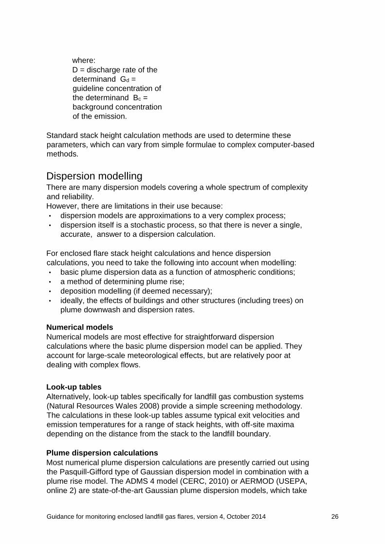
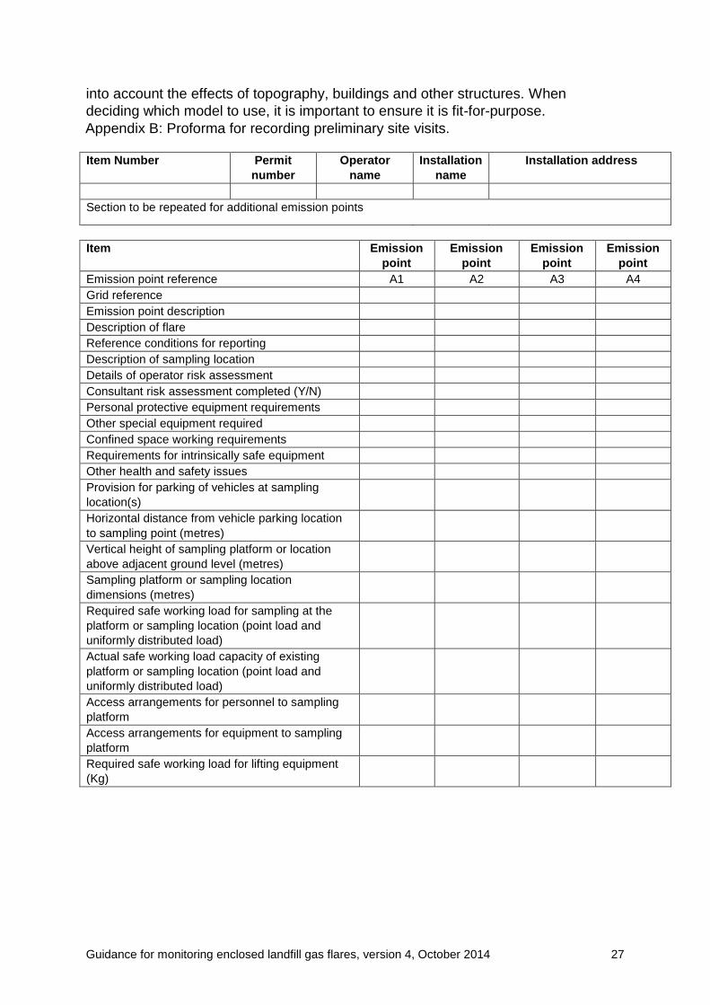
Appendix B: Proforma for recording preliminary site visits.
Item Number Permit
number
Operator
name
Installation
name
Installation address
Section to be repeated for additional emission points
Item Emission
point
Emission
point
Emission
point
Emission
point
Emission point reference A1 A2 A3 A4
Grid reference
Emission point description
Description of flare
Reference conditions for reporting
Description of sampling location
Details of operator risk assessment
Consultant risk assessment completed (Y/N)
Personal protective equipment requirements
Other special equipment required
Confined space working requirements
Requirements for intrinsically safe equipment
Other health and safety issues
Provision for parking of vehicles at sampling
location(s)
Horizontal distance from vehicle parking location
to sampling point (metres)
Vertical height of sampling platform or location
above adjacent ground level (metres)
Sampling platform or sampling location
dimensions (metres)
Required safe working load for sampling at the
platform or sampling location (point load and
uniformly distributed load)
Actual safe working load capacity of existing
platform or sampling location (point load and
uniformly distributed load)
Access arrangements for personnel to sampling
platform
Access arrangements for equipment to sampling
platform
Required safe working load for lifting equipment
(Kg)
Guidance for monitoring enclosed landfill gas flares, version 4, October 2014 28
Appendix C: Further information
on calculations
Data standardisation Make all data handling and calculations as described in fully documented
procedures that comply with standards or equivalent requirements. All
calculation formulae used must conform to the appropriate sampling and
analysis standard.
Emission concentrations should be reported, as appropriate, to reference
conditions of:
• mass concentration
• standard temperature and pressure (STP), that is, 0°C (273K),
101.3 kPa • 3 per cent v/v oxygen
• dry gas.
All flue gas emissions must be reported as concentrations and mass
emissions, together with supporting information using our standard monitoring
report forms.
Conversion from volume concentration to mass
concentration
Emission concentrations are often measured in volume/volume (v/v) terms,
such as parts per million (ppm) or percentages. This approach is most
common for gaseous air emission species, especially when the measurement
is carried out using an instrumental monitoring technique. For example,
carbon monoxide monitors normally present measured data as ppm, while
oxygen meter readouts are given as percentages. For ideal gases,
concentrations measured in volume/volume terms are independent of
temperature and pressure.
This approach has an important advantage for on-line monitoring applications,
as there is no need to correct the readings on the monitors for analyser cell
temperature and pressure conditions. This condition holds as long as the
certificated concentration value of the calibration cylinder and monitor scale
are both given in volume/volume units.
The emission standards for enclosed landfill gas flares are expressed in mass
volume terms (mg/m3). For reporting purposes and to assess compliance,
you will need to convert measured data from volume/volume terms to
mass/volume units.
Guidance for monitoring enclosed landfill gas flares, version 4, October 2014 29
Conversion The conversion from ppm to mg/m3 is straightforward. The relationship is derived
from the ideal gas equations and relies on the fact that one mole of an ideal gas
occupies a volume of 22.4 litres at STP.
As moles and volumes of ideal gases are interchangeable, all that is required to
convert from a ppm concentration to mg/m3 at STP is to multiply the ppm figure by
the ratio of the molecular weight of the emission component to 22.4,
mg/m3 = ppm x Mw
22.4
where:
Mw = molecular weight
For example:
for NOx, Mw = 46 (NOx is expressed as NO2 for
regulatory purposes); for CO, Mw = 28.
Oxygen standardisation
If excess air is added to an enclosed landfill gas flare (for example, to promote
better combustion), measured flue gas emission concentrations of non-
combustible species such as SO2 will fall. However, emission concentrations
only appear to be reducing while, in reality, emission mass rates have
remained constant. Thus, it is necessary to compare concentrations at a
standard oxygen concentration.
However, the relationship between the measured oxygen and measured
emission species concentration is not linear as oxygen from air is added or
removed. For example, halving the flue gas oxygen content does not result in
a doubling of the emission concentration. The oxygen found in the flue gases
is a measure of the excess air over that required for theoretical complete
combustion (termed the stoichiometric air requirement).
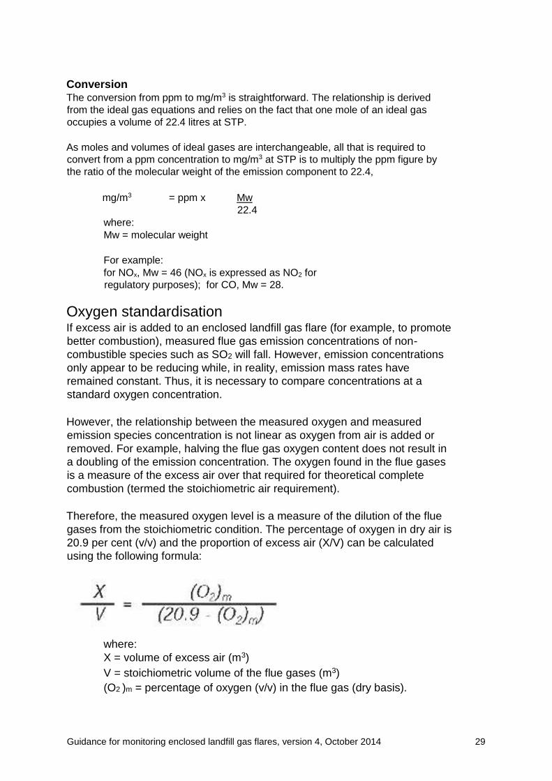
Therefore, the measured oxygen level is a measure of the dilution of the flue
gases from the stoichiometric condition. The percentage of oxygen in dry air is
20.9 per cent (v/v) and the proportion of excess air (X/V) can be calculated
using the following formula:
where:
X = volume of excess air (m3)
V = stoichiometric volume of the flue gases (m3)
(O2 )m = percentage of oxygen (v/v) in the flue gas (dry basis).
Guidance for monitoring enclosed landfill gas flares, version 4, October 2014 30
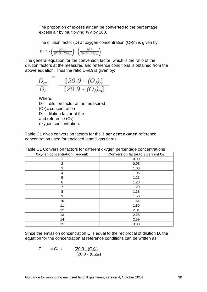
The proportion of excess air can be converted to the percentage
excess air by multiplying X/V by 100.
The dilution factor (D) at oxygen concentration (O2)m is given by:
The general equation for the conversion factor, which is the ratio of the
dilution factors at the measured and reference conditions is obtained from the
above equation. Thus the ratio Dm/Dr is given by:
Where:
Dm = dilution factor at the measured
(O2)m concentration
Dr = dilution factor at the
and reference (O2)r
oxygen concentration.
Table C1 gives conversion factors for the 3 per cent oxygen reference
concentration used for enclosed landfill gas flares.
Table C1 Conversion factors for different oxygen percentage concentrations Oxygen concentration (percent) Conversion factor to 3 percent O2
1 0.90
2 0.95
3 1.00
4 1.06
5 1.13
6 1.20
7 1.29
8 1.38
9 1.50
10 1.64
11 1.80
12 2.01
13 2.26
14 2.59
15 3.03
Since the emission concentration C is equal to the reciprocal of dilution D, the
equation for the concentration at reference conditions can be written as:
Cr = Cm x (20.9 - (O2)r)
(20.9 - (O2)m)

Guidance for monitoring enclosed landfill gas flares, version 4, October 2014 31
Because the reference condition being used for enclosed landfill gas flare is 3
per cent, this equation becomes:
Cr = Cm x 17.9
(20.9 - (O2)m)
Enhanced oxygen Under enhanced oxygen conditions (that is, where oxygen is added to aid
combustion and reduce gas volumes), the conversion to standard oxygen
conditions is not so straightforward.
The percentage of oxygen by volume in dry air is 20.9 per cent. Under normal
combustion conditions, the sum of the carbon dioxide and oxygen
concentrations (measured on a wet basis), together with half the moisture
content of the flue gas (from the combustion of hydrogen in the fuel – not the
fuel moisture) is equivalent to 20.9 per cent of the volume of the flue gas.
That is:
[(CO2) + (O2) + 0.5(H2O)]m = 20.9
Using a modified equation
Under enhanced oxygen conditions, the normal oxygen standardisation
equation is not appropriate as the sum of these items is not 20.9 per cent, but
some larger figure depending on the enhanced oxygen input. Unless the
degree of enhancement is known or can be measured directly, it will be
necessary to estimate it from other measurements such as the oxygen and
carbon dioxide concentration in the flue gas.
If you know the hydrogen/carbon ratio, you can use a modified equation that
takes account of the water emitted as a result of the hydrogen in the fuel. If
the percentage of carbon in the fuel is C and that of hydrogen H, the equation
is as follows:
Moisture correction Moisture content is usually expressed as in volume/volume terms. For
example, as the percentage volume of water vapour in the total wet gas
volume.
Water content is normally determined gravimetrically by passing extracted flue
gases through a weighed drying train. The volume of dried sample gas is
measured and the increase in mass of the drying train is recorded. The ratio
of volumes of water vapour and of dry gas is the same as the ratio of the
Guidance for monitoring enclosed landfill gas flares, version 4, October 2014 32
moles of water vapour and dry gas (treating them both as ideal gases at
STP). The number of moles of water (MW) is found by dividing the increase in
mass of the drying train in grams by the molecular mass of water (18).
The number of moles of dry gas MD is found by dividing the metered volume
of dry gas (in m3 corrected to STP) by 0.0224 (the molar volume of any gas at
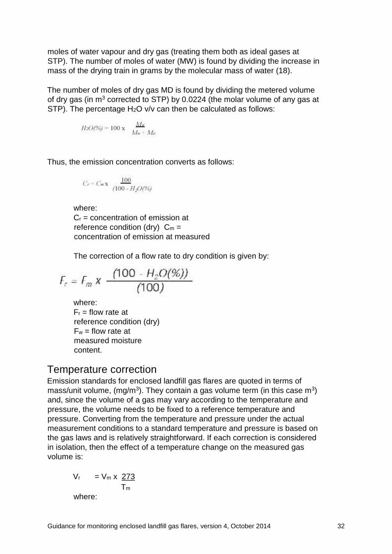
STP). The percentage H2O v/v can then be calculated as follows:
Thus, the emission concentration converts as follows:
where:
Cr = concentration of emission at
reference condition (dry) Cm =
concentration of emission at measured
The correction of a flow rate to dry condition is given by:
where:
Fr = flow rate at
reference condition (dry)
Fw = flow rate at
measured moisture
content.
Temperature correction Emission standards for enclosed landfill gas flares are quoted in terms of
mass/unit volume, (mg/m3). They contain a gas volume term (in this case m3)
and, since the volume of a gas may vary according to the temperature and
pressure, the volume needs to be fixed to a reference temperature and
pressure. Converting from the temperature and pressure under the actual
measurement conditions to a standard temperature and pressure is based on
the gas laws and is relatively straightforward. If each correction is considered
in isolation, then the effect of a temperature change on the measured gas
volume is:
Vr = Vm x 273
Tm
where:
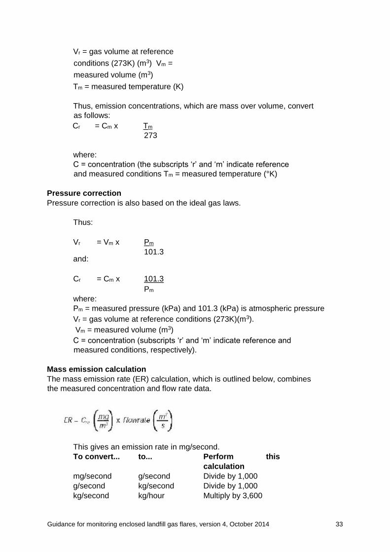
Guidance for monitoring enclosed landfill gas flares, version 4, October 2014 33
Vr = gas volume at reference
conditions (273K) (m3) Vm =
measured volume (m3)
Tm = measured temperature (K)
Thus, emission concentrations, which are mass over volume, convert
as follows:
Cr = Cm x Tm
273
where:
C = concentration (the subscripts ‘r’ and ‘m’ indicate reference
and measured conditions Tm = measured temperature (°K)
Pressure correction
Pressure correction is also based on the ideal gas laws.
Thus:
Vr
and:
= Vm x Pm
101.3
Cr = Cm x 101.3
Pm
where:
Pm = measured pressure (kPa) and 101.3 (kPa) is atmospheric pressure
Vr = gas volume at reference conditions (273K)(m3).
Vm = measured volume (m3)
C = concentration (subscripts ‘r’ and ‘m’ indicate reference and
measured conditions, respectively).
Mass emission calculation
The mass emission rate (ER) calculation, which is outlined below, combines
the measured concentration and flow rate data.
This gives an emission rate in mg/second.
To convert... to... Perform this
calculation
mg/second g/second Divide by 1,000
g/second kg/second Divide by 1,000
kg/second kg/hour Multiply by 3,600
Guidance for monitoring enclosed landfill gas flares, version 4, October 2014 34
It is essential that the emission concentration and emission flow
rate are expressed at the same conditions (temperature, pressure,
water content and oxygen content).
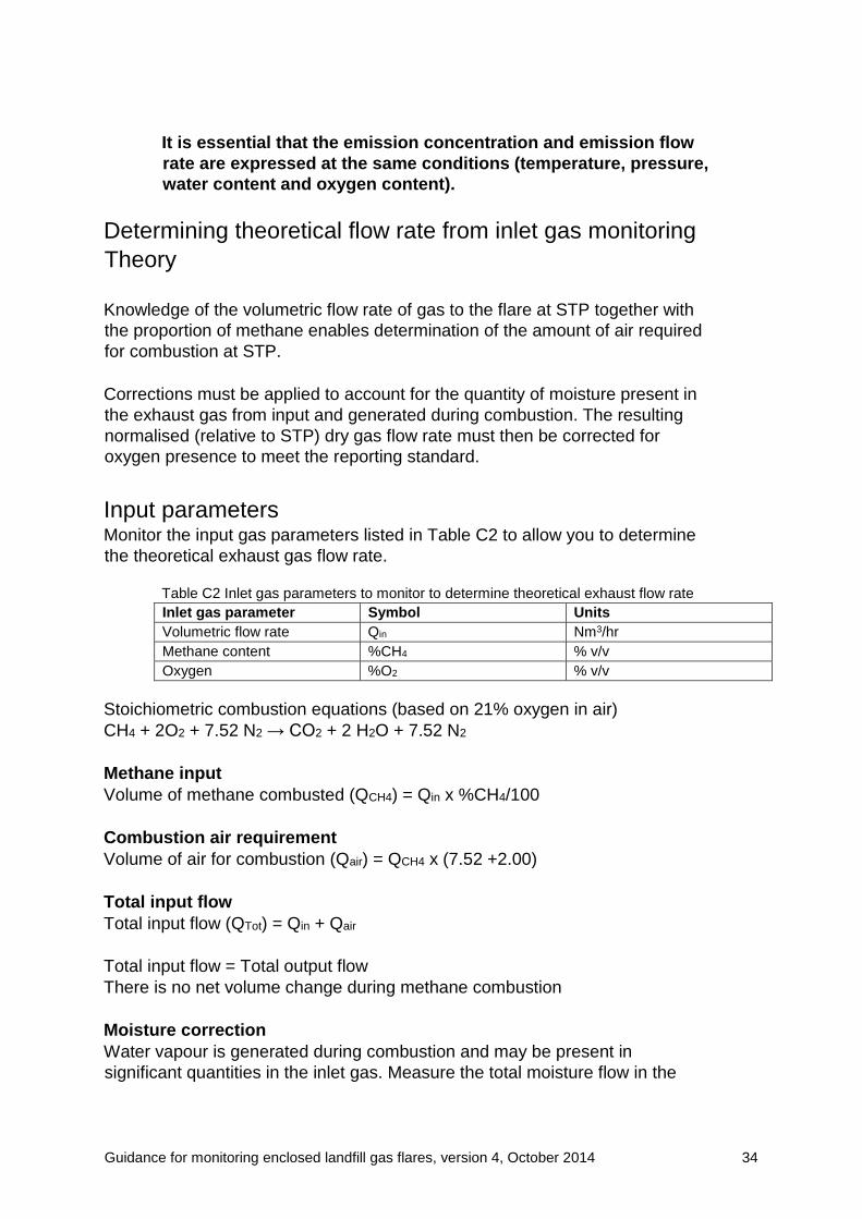
Determining theoretical flow rate from inlet gas monitoring
Theory
Knowledge of the volumetric flow rate of gas to the flare at STP together with
the proportion of methane enables determination of the amount of air required
for combustion at STP.
Corrections must be applied to account for the quantity of moisture present in
the exhaust gas from input and generated during combustion. The resulting
normalised (relative to STP) dry gas flow rate must then be corrected for
oxygen presence to meet the reporting standard.
Input parameters Monitor the input gas parameters listed in Table C2 to allow you to determine
the theoretical exhaust gas flow rate.
Table C2 Inlet gas parameters to monitor to determine theoretical exhaust flow rate
Inlet gas parameter Symbol Units
Volumetric flow rate Qin Nm3/hr
Methane content %CH4 % v/v
Oxygen %O2 % v/v
Stoichiometric combustion equations (based on 21% oxygen in air)
CH4 + 2O2 + 7.52 N2 → CO2 + 2 H2O + 7.52 N2
Methane input
Volume of methane combusted (QCH4) = Qin x %CH4/100
Combustion air requirement
Volume of air for combustion (Qair) = QCH4 x (7.52 +2.00)
Total input flow
Total input flow (QTot) = Qin + Qair
Total input flow = Total output flow
There is no net volume change during methane combustion
Moisture correction
Water vapour is generated during combustion and may be present in
significant quantities in the inlet gas. Measure the total moisture flow in the
Guidance for monitoring enclosed landfill gas flares, version 4, October 2014 35
exhaust gas and correct the total output flow to account for the moisture
content to give the normalised dry gas flow rate (Qdry).
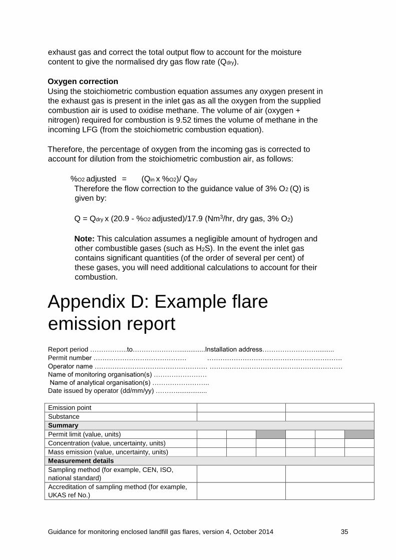
Oxygen correction
Using the stoichiometric combustion equation assumes any oxygen present in
the exhaust gas is present in the inlet gas as all the oxygen from the supplied
combustion air is used to oxidise methane. The volume of air (oxygen +
nitrogen) required for combustion is 9.52 times the volume of methane in the
incoming LFG (from the stoichiometric combustion equation).
Therefore, the percentage of oxygen from the incoming gas is corrected to
account for dilution from the stoichiometric combustion air, as follows:
%O2 adjusted = (Qin x %O2)/ Qdry
Therefore the flow correction to the guidance value of 3% O2 (Q) is
given by:
Q = Qdry x (20.9 - %O2 adjusted)/17.9 (Nm3/hr, dry gas, 3% O2)
Note: This calculation assumes a negligible amount of hydrogen and
other combustible gases (such as H2S). In the event the inlet gas
contains significant quantities (of the order of several per cent) of
these gases, you will need additional calculations to account for their
combustion.
Appendix D: Example flare
emission report
Report period ……………..to…………………..............Installation address……………………..........
Permit number …………………………………… …………………………………………………….
Operator name …………………………………………… ……………………………………………………
Name of monitoring organisation(s) ……………………
Name of analytical organisation(s) ……………………..
Date issued by operator (dd/mm/yy) ……….................
Emission point
Substance
Summary
Permit limit (value, units)
Concentration (value, uncertainty, units)
Mass emission (value, uncertainty, units)
Measurement details
Sampling method (for example, CEN, ISO,
national standard)
Accreditation of sampling method (for example,
UKAS ref No.)
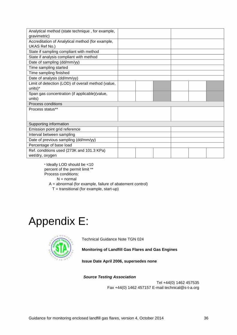
Guidance for monitoring enclosed landfill gas flares, version 4, October 2014 36
Analytical method (state technique , for example,
gravimetric)
Accreditation of Analytical method (for example,
UKAS Ref No.)
State if sampling compliant with method
State if analysis compliant with method
Date of sampling (dd/mm/yy)
Time sampling started
Time sampling finished
Date of analysis (dd/mm/yy)
Limit of detection (LOD) of overall method (value,
units)*
Span gas concentration (if applicable)(value,
units)
Process conditions
Process status**
Supporting information
Emission point grid reference
Interval between sampling
Date of previous sampling (dd/mm/yy)
Percentage of base load
Ref. conditions used (273K and 101.3 KPa)
wet/dry, oxygen
* Ideally LOD should be <10
percent of the permit limit **
Process conditions: N = normal A = abnormal (for example, failure of abatement control) T = transitional (for example, start-up)
Appendix E:
Technical Guidance Note TGN 024
Monitoring of Landfill Gas Flares and Gas Engines
Issue Date April 2006, supersedes none
Source Testing Association
Tel +44(0) 1462 457535
Fax +44(0) 1462 457157 E-mail [email protected]
Guidance for monitoring enclosed landfill gas flares, version 4, October 2014 37
Background
Natural Resources Wales Guidance on Landfill gas flare monitoring outlines a
monitoring strategy that requires pre-installation of an extraction system to
take a representative sample from above the flame within the enclosed flare
stack. It presumes (unless demonstrated otherwise) that there may be non-
uniform distribution of gas concentrations across the sampling plane and that
a multipoint sample probe/sampling would normally be required.
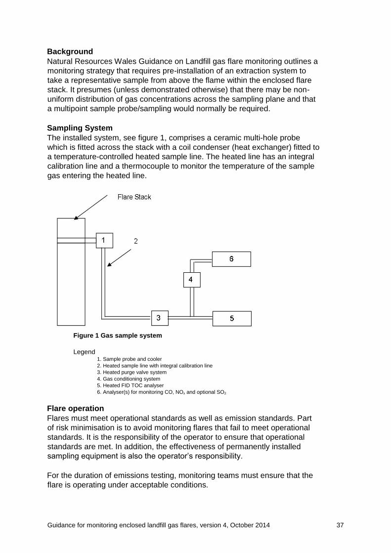
Sampling System
The installed system, see figure 1, comprises a ceramic multi-hole probe
which is fitted across the stack with a coil condenser (heat exchanger) fitted to
a temperature-controlled heated sample line. The heated line has an integral
calibration line and a thermocouple to monitor the temperature of the sample
gas entering the heated line.
Figure 1 Gas sample system
Legend 1. Sample probe and cooler 2. Heated sample line with integral calibration line 3. Heated purge valve system 4. Gas conditioning system 5. Heated FID TOC analyser 6. Analyser(s) for monitoring CO, NOx and optional SO2
Flare operation
Flares must meet operational standards as well as emission standards. Part
of risk minimisation is to avoid monitoring flares that fail to meet operational
standards. It is the responsibility of the operator to ensure that operational
standards are met. In addition, the effectiveness of permanently installed
sampling equipment is also the operator’s responsibility.
For the duration of emissions testing, monitoring teams must ensure that the
flare is operating under acceptable conditions.

Guidance for monitoring enclosed landfill gas flares, version 4, October 2014 38
Flares can be operating outside acceptable standards; if for example:
• The flame extends beyond the shroud at any time (it should be below the
sampling ports) – elevated or un-enclosed flares must not be monitored.
• On noting the operating temperature, it is outside the design range by
more than 100º C. Normal operation for most designs is 1000º C.
• The temperature fluctuates by more than 100º C over a 5 minute period
(indicative of problems in the gas field so may be noted as a factor in
representativity of data).
• The thermocouple temperature is significantly different from that shown
on the flare control temperature instrument.
• There are missing or broken louvers on the air control (this will affect
estimation of flow).
• The orifice plate or similar flow gauge is not operational.
• There is a strong smell of landfill gas in the compound.
• A recent value for gas composition is not available.
Monitoring
The main measurements that are to be carried out are;
• Nitrogen Oxides (NOx) to BS EN 14792:2005
• Carbon Monoxide (CO) to BS EN 15058:2006
• Total Organic Compounds (TOC) to BS EN 13526
Optional:
• Sulphur Dioxide (SO2) to BS 6069 part 4.4 (ISO7935)
Preparation at site
The test team is to verify, before sampling, that the heated line system is
functioning correctly by ensuring that:
• the heated line has no hot or cold spots within its length;
• the temperature of the sample gas (downstream of the cooler and before
the heated line) is above 180ºC;
• after the analyser(s) system is connected, there are no leaks by following
the procedure in BS EN 14792 paragraph 8.4.2.3;
• the analysers must be calibrated by introduction of span and zero gases
directly into the analyser and then via the sample system. The difference
between the two readings must be less than two per cent of the
estimated measured concentration as stated in the relevant standards.
Measurements
The sampling period for the measurement must be determined and should
cover at least one cycle of flare operation. The analyser data recording
system must be able to record one minute averages.
On completion of the sampling period you must carry out a check of the
sample system as stated in the relevant standards.

Guidance for monitoring enclosed landfill gas flares, version 4, October 2014 39
Glossary
Absorption
This is a process in which a gas is taken up by a liquid or a solid.
Adsorption
This is a process in which a layer of atoms or molecules of a substance collect
on the surface of a solid or liquid.
Biodegradable waste
Any organic waste that is capable of undergoing anaerobic or aerobic
decomposition, such as food, garden waste, paper and paperboard.
Chemiluminescence
This is the emission of light during a chemical reaction.
Deposition
This is the removal of particles or gases from a gas stream through surface
adsorption, impaction, and so on. In the context of the flare gas emissions,
this includes dry deposition –- direct absorption or uptake on soil and
vegetation. It may also include wet deposition – removal in rainfall passing
through the plume as it disperses.
Design capacity
The maximum gas flow rate the flare is designed to burn at.
Dew point
Temperature at which the water vapour contained within a gas mixture will
condense to form liquid water.
Dispersion
The tendency for components of the flare/stack emission to spread out from
the path they would be expected to follow as a result of mechanical mixing
and thermal kinetic energy. It causes dilution of the components in the free
atmosphere.
Duct
This is an enclosed structure through which gases travel.
Enclosed flare
This is a flare in which combustion conditions are improved by enclosure of
the flame in a shroud.
Flare
Guidance for monitoring enclosed landfill gas flares, version 4, October 2014 40
Structure designed to facilitate combustion of landfill gas under controlled
conditions.
Flue
See Duct.
Fugitive gas
The proportion of emissions of landfill gas that are not accountable by known
point sources on site. Typically, diffusive loss or leaching through the surface
of a landfill generates fugitive losses.
Gravimetric
A method for determination of particle concentrations in air by direct weighing
of the mass present in a collected sample.
Greenhouse gas
This is a gas that, when present in the atmosphere, contributes to global
warming because of its radiative properties.
Intra-red (IR)
A form of electromagnetic radiation, longer in wavelength than visible light
Isokinetic sampling
Condition required when sampling particles at which the gas entering a
sampling nozzle is at the same velocity and direction as the bulk flow of gas in
the sample duct or stack. This condition minimises any sampling error that
might arise due to inertial properties of the particles.
Landfill gas
All gases generated from the landfilled waste.
Sampling plane
The plane normal to the centreline of the duct at the sampling position.
Sampling point
The point(s) on the sample plane where the sample is collected.
Sampling ports
Points on the wall of the stack, duct or flue through which access to the
emission gas can be gained.
Semi-volatile organic compounds
The volatility of a pure organic compound depends on its vapour pressure.
The form in which a substance is present in air is dependent upon the vapour
pressure. Typically, in air, an organic compound with a vapour pressure
greater than 10–7 atmosphere will be gaseous. At a vapour pressure below
10–11 atmosphere, the compound is almost exclusively in the particle phase.
Guidance for monitoring enclosed landfill gas flares, version 4, October 2014 41
In between these ranges, compounds can be present in both gaseous and
particle phases depending upon temperature and pressure; these are referred
to as semi volatile organic compounds.
Stack
This is a structure (that is, chimney) through which emissions are released to
atmosphere.
Stoichiometric
These are the exact proportions in which substances react. For combustion,
the theoretical minimum amount of air or oxygen required to consume the fuel
completely.
Tenax
Proprietary medium used for the adsorption and collection of organic
compounds from sample gas streams or air. Subsequent desorption of the
collected material allows determination in the laboratory.
Ultraviolet (UV)
A form of electromagnetic radiation, shorter in wavelength than visible light.
NMVOCs (Non-methane Volatile organic compound)
Organic compounds that can be measured in the gas phase at ambient
temperature (VOCs) but excluding methane, the predominant VOC in
landfill gas.
VOCs (Volatile organic compound)
Organic compounds that can be measured in the gas phase at ambient
temperature
UV fluorescence
A process by which, some substances emit radiation when excited by
radiation of shorter wavelength (UV). The emitted radiation can be used to
determine concentrations of the particular substance.
Acronyms
BSI British Standards Institution
CEN Comité Européen de Normalisation
CH4 Methane
CO Carbon monoxide
CO2 Carbon dioxide
Defra Department for Environment, Food and Rural Affairs
Guidance for monitoring enclosed landfill gas flares, version 4, October 2014 42
EN Norm Européenne (European Standard)
FID Flame ionisation detection
FTIR Fourier transform infrared spectrometry
GC Gas chromatography
GC–FID Gas chromatography with flame ionisation detection
GC–HRMS Gas Chromatography with detection by high resolution mass
spectrometry
GC–MS Gas Chromatography with detection by mass spectrometry
HCl Hydrogen chloride
HF Hydrogen fluoride
HPLC High performance liquid chromatography
HSE Health and Safety Executive
IR Infra-red
ISO International Standards Organisation
MCERTS Natural Resources Wales’s Monitoring Certification Scheme
MS Mass spectrometry
NDIR Non-dispersive infra-red spectrometry
NDUV Non-dispersive ultraviolet spectrometry
Nm Nanometre (10–9 of a metre)
NMVOC Non-methane volatile organic compound
NO Nitric oxide
NO2 Nitrogen dioxide
NOx Nitrogen oxides (sum of NO and NO2)
PCDDs Polychlorinated dibenzo-p-dioxins
PCDFs Polychlorinated dibenzo furans
PID Photo ionisation detector
PM10 Particulate matter of 10 microns (10-6 of a metre) or less in
diameter
ppb Part per billion (1 ppb is 1 volume of gas in 109 volumes of air)
PPE Personal protection equipment
ppm Part per million (1 ppm is 1 volume of gas in 106 volumes of
air)
PTFE Polytetrafluoroethylene
PUF Polyurethane foam
SO2 Sulphur dioxide
STA Source Testing Association
STP Standard temperature and pressure (0oC and 1 atmosphere
pressure)
UK United Kingdom
Guidance for monitoring enclosed landfill gas flares, version 4, October 2014 43
UKAS United Kingdom Accreditation Service
USEPA United States Environmental Protection Agency
UV Ultraviolet
VDI Verein Deutscher Ingenieure (German national standards
body)
VOCs Volatile organic compounds
References British Standards Institution (BSI) (1998) BS EN 1911 Parts 1, 2 and 3.
Stationary source emissions. Manual method of determination of HCI. BSI, London.
British Standards Institution (BSI) (1999) BS EN 12619.
Stationary source emissions. Determination of the mass concentration of total gaseous
organic carbon at low concentrations in flue gases. Continuous flame ionization detector
method. BSI,
London.
Cambridge Environmental Research Consultants (2010)
Industrial air pollution model ADMS 4.
Council of the European Union (1999)
Directive 1999/31/EC on the landfilling of wastes. Official Journal of European Communities,
L182, pp. 1–19.
Council of the European Union (2000)
Directive on the incineration of waste (2000/76/EC). Official Journal of the European Union,
L332, pp. 91–111.
Council of the European Union (2001)
Directive on the limitation of emissions of certain pollutants into the air from large combustion
plants (2001/80/EC). Official Journal of the European Union, L309, pp. 1–21.
Department for Environment, Food and Rural Affairs (Defra) (2007)
The Air Quality Strategy for England, Scotland, Wales and Northern Ireland. Volume 1.
ID 5611194 07/07. The Stationary Office.
Department of Environment, Transport and the Regions (DETR), Natural Resources Wales
and Institute for Environmental Health (2000)
Guidelines for environmental risk assessment and management. The Stationary Office,
London.
Environment Agency (2008)
Assessment of point source releases and cost-benefit analysis Part 2. EPR H1
Environment Agency (2008a)
Monitoring Certification Scheme MCERTS. Manual stack-emission monitoring: performance
standard for organisations. Version 6.
Environment Agency (2010a)
Guidance on the management of landfill gas, Bristol
Guidance for monitoring enclosed landfill gas flares, version 4, October 2014 44
Environment Agency (2010b)
Guidance for monitoring landfill gas engines, Bristol
Environment Agency (2010c)
Guidance on gas treatment technologies for landfill gas engines, Bristol
Environment Agency (2010d)
Guidance for monitoring landfill gas surface emissions, Bristol
Her Majesty’s Inspectorate of Pollution (HMIP) (1993)
Guidelines on discharge stack heights for polluting emissions. Technical Guidance Note
(Dispersion) D1. HMSO, London.
International Standards Organisation (ISO) (1995)
Guide to the expressions of uncertainty in analytical measurement. ISO, Geneva.
International Standards Organisation (ISO) (1996)
ISO 10849. Stationary source emissions. Determination of the mass concentration of nitrogen
oxides. Performance characteristics of automated measuring systems. ISO, Geneva.
International Standards Organisation (ISO) (1998)
ISO 11632. Stationary source emissions. Determination of mass concentration of sulphur
dioxide. Ion chromatography method. ISO, Geneva.
International Standards Organisation (ISO) (2001)
ISO 12039. Stationary source emissions. Determination of carbon monoxide, carbon dioxide
and oxygen. Performance characteristics and calibration of automated measuring systems.
ISO,
Geneva.
International Standards Organisation (ISO) (2003)
ISO 9096. Stationary source emissions. Manual determination of mass concentration of
particulate matter. ISO, Geneva.
Source Testing Association (STA) (2000)
Example risk assessments for stack sampling operations. Document No. HS1057-00. STA,
Hitchin.
Source Testing Association (STA) (2001a)
Hazards, risk and risk control in stack testing operations. Version 5. STA, Hitchin.
Source Testing Association (STA) (2001b)
Guidance on assessing measurement uncertainty in stack emissions monitoring. Quality
Guidance Note QGN1. STA, Hitchin.
The Landfill (England and Wales) Regulations 2002.
SI 2002 No. 1559. The Stationery Office, London.
United States Environmental Protection Agency (USEPA) (online 1).
Method 19. Determination of sulphur dioxide removal efficiency and particulate matter,
sulphur dioxide and nitrogen oxide emission rates. See EPA website.
United States Environmental Protection Agency (USEPA) (online 2).
Technology Transfer Network Support Center for Regulatory Air Models. AERMOD dispersion
model. See EPA website.

Guidance for monitoring enclosed landfill gas flares, version 4, October 2014 45