
Guia Retainer
8
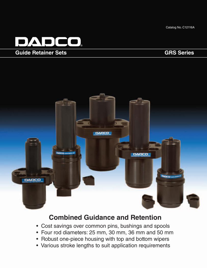
Catalog No. C12116A Guide Retainer Sets GRS Series Combined Guidance and Retention • Cost savings over common pins, bushings and spools • Four rod diameters: 25 mm, 30 mm, 36 mm and 50 mm • Robust one-piece housing with top and bottom wipers • Various stroke lengths to suit application requirements ®
-
Upload
jose-carlos-meza-saucedo -
Category
Documents
-
view
256 -
download
0
description
catalogo retainer
Transcript of Guia Retainer
Catalog No. C12116A
Guide Retainer Sets GRS Series
Combined Guidance and Retention• Cost savings over common pins, bushings and spools• Four rod diameters: 25 mm, 30 mm, 36 mm and 50 mm• Robust one-piece housing with top and bottom wipers • Various stroke lengths to suit application requirements
®
Guide Retainer Sets
734.207.1100 • 800.DADCO.USA • fax 734.207.2222 • www.dadco.net2®
®
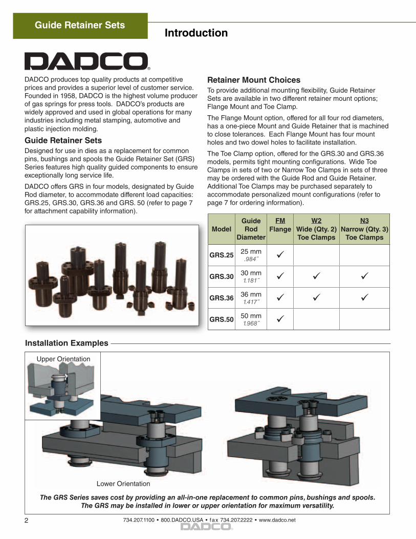
DADCO produces top quality products at competitive prices and provides a superior level of customer service. Founded in 1958, DADCO is the highest volume producer of gas springs for press tools. DADCO’s products are widely approved and used in global operations for many industries including metal stamping, automotive and plastic injection molding.
Guide Retainer SetsDesigned for use in dies as a replacement for common pins, bushings and spools the Guide Retainer Set (GRS) Series features high quality guided components to ensure exceptionally long service life.
DADCO offers GRS in four models, designated by Guide Rod diameter, to accommodate different load capacities: GRS.25, GRS.30, GRS.36 and GRS. 50 (refer to page 7 for attachment capability information).
Retainer Mount ChoicesTo provide additional mounting flexibility, Guide Retainer Sets are available in two different retainer mount options; Flange Mount and Toe Clamp.
The Flange Mount option, offered for all four rod diameters, has a one-piece Mount and Guide Retainer that is machined to close tolerances. Each Flange Mount has four mount holes and two dowel holes to facilitate installation.
The Toe Clamp option, offered for the GRS.30 and GRS.36 models, permits tight mounting configurations. Wide Toe Clamps in sets of two or Narrow Toe Clamps in sets of three may be ordered with the Guide Rod and Guide Retainer. Additional Toe Clamps may be purchased separately to accommodate personalized mount configurations (refer to page 7 for ordering information).
ModelGuide Rod
Diameter
FMFlange
W2Wide (Qty. 2) Toe Clamps
N3Narrow (Qty. 3)
Toe Clamps
GRS.25 25 mm.984˝
GRS.30 30 mm1.181˝
GRS.36 36 mm1.417˝
GRS.50 50 mm1.968˝
Introduction
Installation Examples
Lower Orientation
The GRS Series saves cost by providing an all-in-one replacement to common pins, bushings and spools. The GRS may be installed in lower or upper orientation for maximum versatility.
Upper Orientation
734.207.1100 • 800.DADCO.USA • fax 734.207.2222 • www.dadco.net
Guide Retainer Sets
3®
GRS.30
ø43 f 71.693
19.748
6 .236
B
311.220
ø471.850
39.41.551
3 mm .118
HEX
9.27.365
6 .236
ø50 f 71.968
21.827
ø883.465
6 .236
B
4 mm
.157
HEX
52.42.063
29.881.176ø69
2.717
8.315
441.732
ø542.126
M10 SHCS
3/8
120°
36°
6 .236
12.472
10.66.420
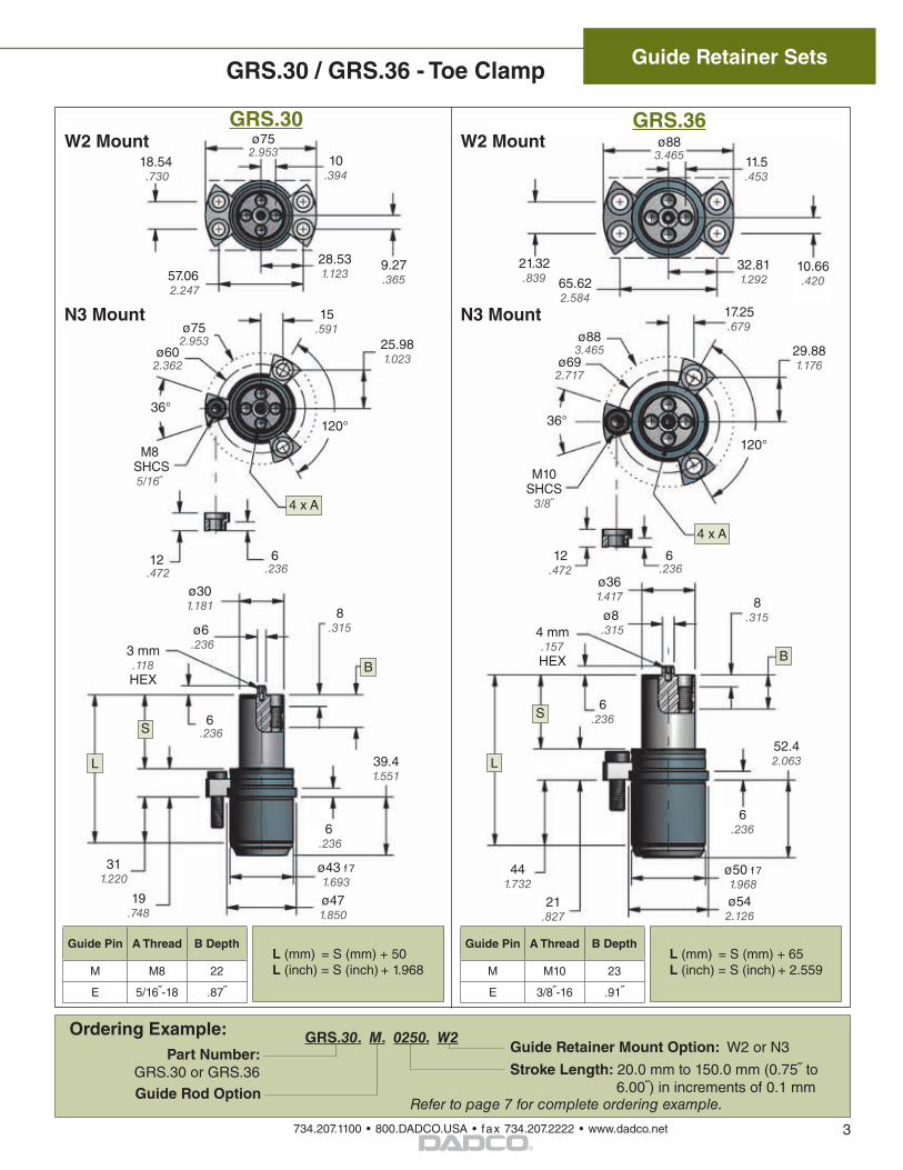
GRS.30 / GRS.36 - Toe Clamp
Ordering Example: GRS.30. M. 0250. W2
Stroke Length: 20.0 mm to 150.0 mm (0.75 to 6.00) in increments of 0.1 mm
Part Number: GRS.30 or GRS.36
Guide Rod Option Refer to page 7 for complete ordering example.
Guide Retainer Mount Option: W2 or N3
W2 MountGRS.36
Guide Pin A Thread B Depth
M M8 22
E 5/16-18 .87
ø301.181
ø6 .236
S
8.315
L
6 .236
12 .472
S
L
ø361.417
6.236
N3 Mount
W2 Mount
N3 Mount
ø8 .315
17.25.679
4 x A
4 x A
120°
25.981.023
15.591ø75
2.953
36°
ø602.362
M8 SHCS
5/16
L (mm) = S (mm) + 50L (inch) = S (inch) + 1.968
Guide Pin A Thread B Depth
M M10 23
E 3/8-16 .91
L (mm) = S (mm) + 65L (inch) = S (inch) + 2.559
10.394
18.54 .730
57.06 2.247
28.531.123
32.811.29265.62
2.584
21.32.839
11.5.453
ø752.953
ø883.465
Guide Retainer Sets
734.207.1100 • 800.DADCO.USA • fax 734.207.2222 • www.dadco.net4®
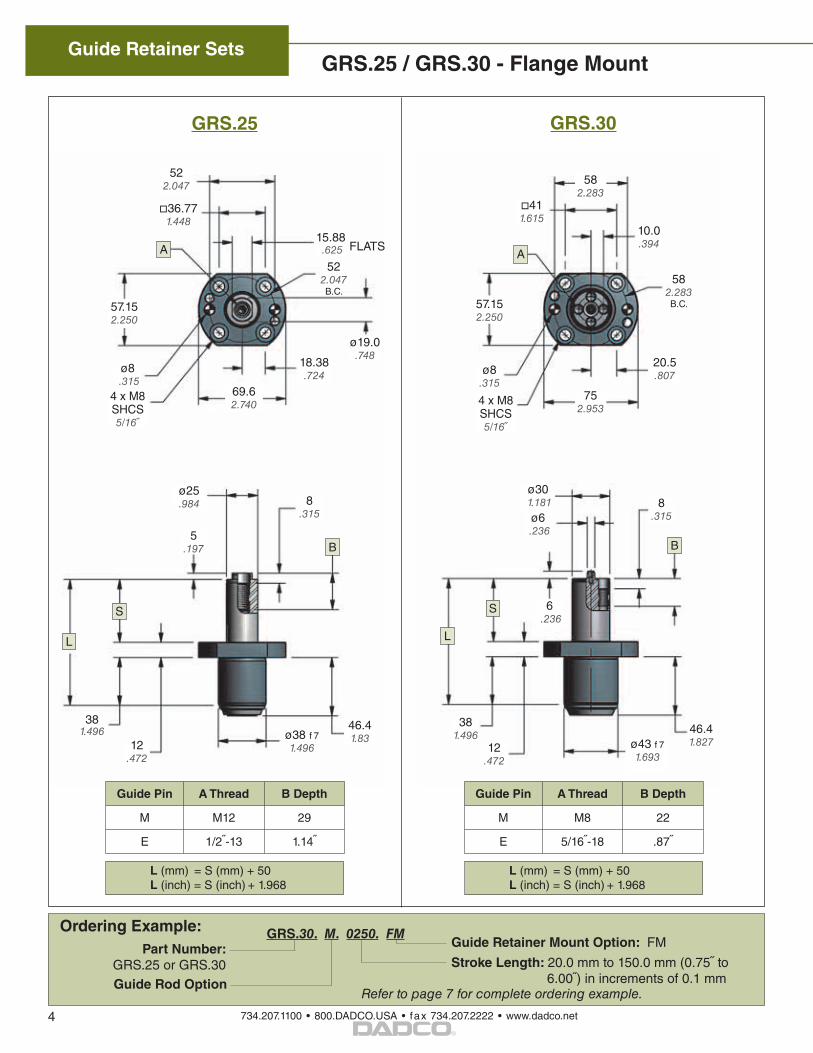
GRS.25 / GRS.30 - Flange Mount
ø6 .236
6 .236
ø43 f 71.693
381.496
12.472
582.283B.C.57.15
2.250
411.615
A
ø8 .315
ø30 1.181
4 x M8 SHCS5/16
S
L
582.283
10.0.394
752.953
46.41.827
4 x M8 SHCS5/16
36.771.448
522.047
57.152.250
A
46.41.83ø38 f 7
1.49612.472
ø19.0.748
69.62.740
5.197
ø25.984
FLATS
S
522.047 B.C.
381.496
B
L
15.88 .625
Guide Pin A Thread B Depth
M M8 22
E 5/16-18 .87
Guide Pin A Thread B Depth
M M12 29
E 1/2-13 1.14
Ordering Example: GRS.30. M. 0250. FM
Stroke Length: 20.0 mm to 150.0 mm (0.75 to 6.00) in increments of 0.1 mm
Part Number: GRS.25 or GRS.30
Guide Rod Option Refer to page 7 for complete ordering example.
Guide Retainer Mount Option: FM
ø8 .315
B
8.315
8.315
L (mm) = S (mm) + 50L (inch) = S (inch) + 1.968
L (mm) = S (mm) + 50L (inch) = S (inch) + 1.968
GRS.30GRS.25
18.38.724
20.5.807
734.207.1100 • 800.DADCO.USA • fax 734.207.2222 • www.dadco.net
Guide Retainer Sets
5®
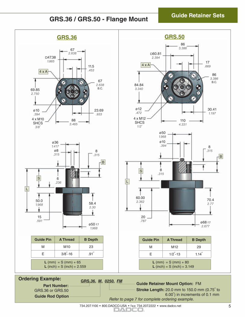
GRS.36 / GRS.50 - Flange Mount
Ordering Example: GRS.36. M. 0250. FM
Stroke Length: 20.0 mm to 150.0 mm (0.75 to 6.00) in increments of 0.1 mm
Part Number: GRS.36 or GRS.50
Guide Rod Option Refer to page 7 for complete ordering example.
Guide Retainer Mount Option: FM
ø50 f 71.968
15.591
4 x M10 SHCS
3/8
4 x A
ø361.417
ø8 .315
S
672.638 B.C.
L
58.42.30
6 .236
50.01.968
69.852.750
47.38 1.865
ø10 .394
672.638
11.5.453
883.465
ø68 f 72.677
70.42.77
20.787
60.812.394
84.843.340
4 x M12 SHCS
1/2
863.386
ø12.472
1104.331
ø501.968
8.315
8.315
ø10 .394
S
4 x A
B
863.386 B.C.
60.002.362
L
Guide Pin A Thread B Depth
M M10 23
E 3/8-16 .91
Guide Pin A Thread B Depth
M M12 29
E 1/2-13 1.14
8.315
B
L (mm) = S (mm) + 65L (inch) = S (inch) + 2.559
L (mm) = S (mm) + 80L (inch) = S (inch) + 3.149
GRS.36 GRS.50
17.669
30.411.197
23.69.933
Guide Retainer Sets
734.207.1100 • 800.DADCO.USA • fax 734.207.2222 • www.dadco.net6®
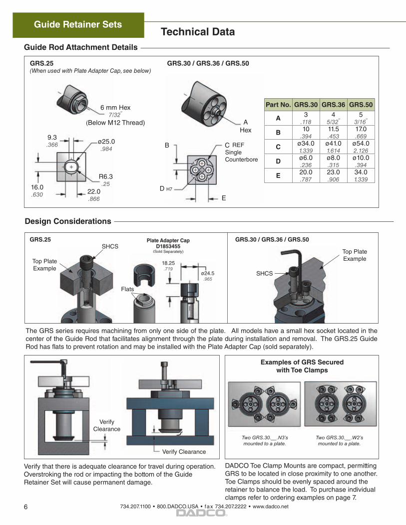
Guide Rod Attachment Details
GRS.25(When used with Plate Adapter Cap, see below)
9.3.366
16.0.630
6 mm Hex7/32
(Below M12 Thread)
ø25.0.984
22.0.866
R6.3.25
GRS.30 / GRS.36 / GRS.50
A Hex
E
C
D H7
B REFSingle Counterbore
Part No. GRS.30 GRS.36 GRS.50
A 3.118
45/32
53/16
B 10.394
11.5.453
17.0.669
C ø34.01.339
ø41.01.614
ø54.02.126
D ø6.0.236
ø8.0.315
ø10.0.394
E 20.0.787
23.0.906
34.01.339
Design Considerations
Verify Clearance
Technical Data
Top Plate Example
SHCS
The GRS series requires machining from only one side of the plate. All models have a small hex socket located in the center of the Guide Rod that facilitates alignment through the plate during installation and removal. The GRS.25 Guide Rod has flats to prevent rotation and may be installed with the Plate Adapter Cap (sold separately).
Verify that there is adequate clearance for travel during operation. Overstroking the rod or impacting the bottom of the Guide Retainer Set will cause permanent damage.
GRS.25SHCS
Top Plate Example
GRS.30 / GRS.36 / GRS.50
DADCO Toe Clamp Mounts are compact, permitting GRS to be located in close proximity to one another. Toe Clamps should be evenly spaced around the retainer to balance the load. To purchase individual clamps refer to ordering examples on page 7.
Verify Clearance
Two GRS.30.__.N3’smounted to a plate.
Two GRS.30.__.W2’s mounted to a plate.
18.25.719
ø24.5.965
Plate Adapter Cap D1853455
(Sold Separately)
Flats
Examples of GRS Secured with Toe Clamps
734.207.1100 • 800.DADCO.USA • fax 734.207.2222 • www.dadco.net
Guide Retainer Sets
7®
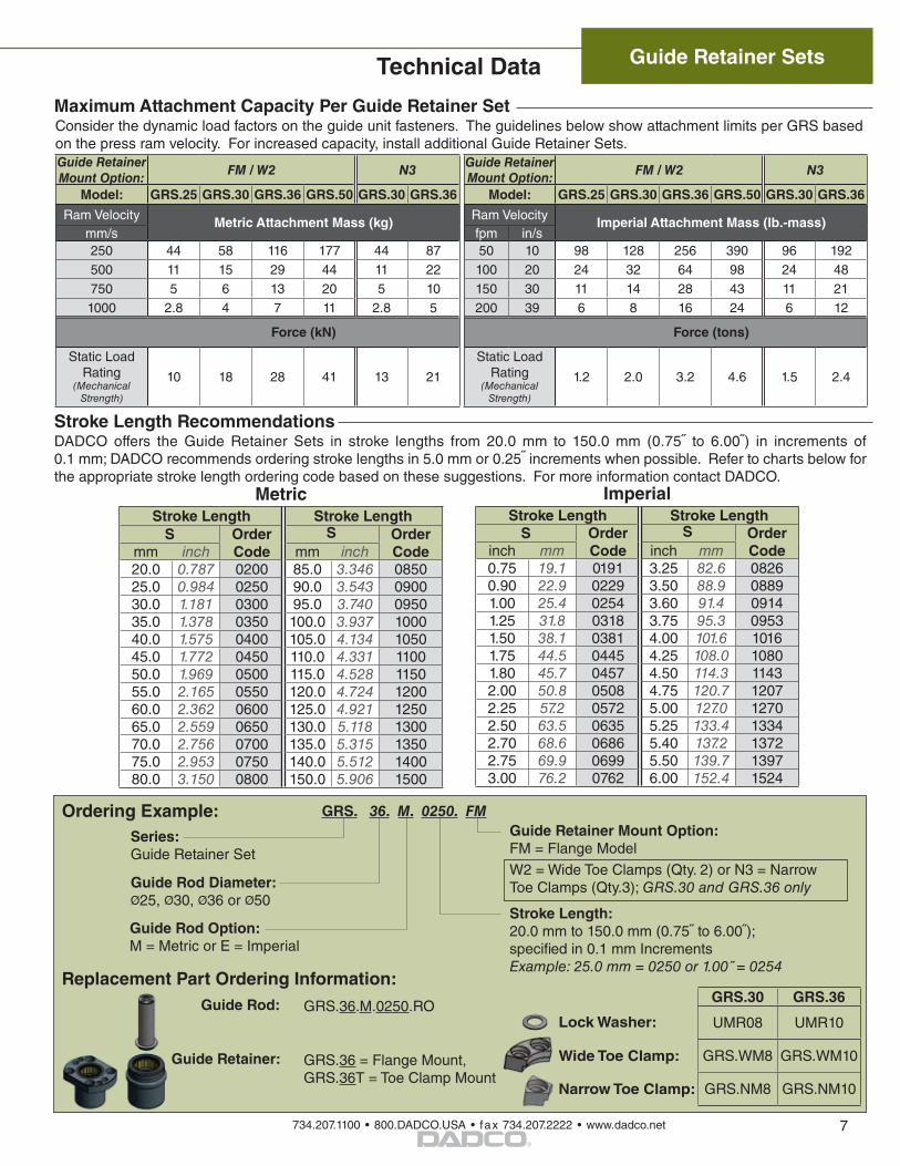
Consider the dynamic load factors on the guide unit fasteners. The guidelines below show attachment limits per GRS based on the press ram velocity. For increased capacity, install additional Guide Retainer Sets.
Maximum Attachment Capacity Per Guide Retainer Set
Guide Retainer Mount Option: FM / W2 N3 Guide Retainer
Mount Option: FM / W2 N3
Model: GRS.25 GRS.30 GRS.36 GRS.50 GRS.30 GRS.36 Model: GRS.25 GRS.30 GRS.36 GRS.50 GRS.30 GRS.36
Ram Velocity Metric Attachment Mass (kg) Ram Velocity Imperial Attachment Mass (lb.-mass)mm/s fpm in/s250 44 58 116 177 44 87 50 10 98 128 256 390 96 192500 11 15 29 44 11 22 100 20 24 32 64 98 24 48750 5 6 13 20 5 10 150 30 11 14 28 43 11 211000 2.8 4 7 11 2.8 5 200 39 6 8 16 24 6 12
Force (kN) Force (tons)
Static Load Rating
(Mechanical Strength)
10 18 28 41 13 21
Static Load Rating
(Mechanical Strength)
1.2 2.0 3.2 4.6 1.5 2.4
Ordering Example: GRS. 36. M. 0250. FM
Stroke Length: 20.0 mm to 150.0 mm (0.75 to 6.00); specified in 0.1 mm Increments Example: 25.0 mm = 0250 or 1.00 = 0254
Series:Guide Retainer Set
Guide Rod Diameter:Ø25, Ø30, Ø36 or Ø50
Guide Rod Option: M = Metric or E = Imperial
Guide Retainer Mount Option: FM = Flange Model
W2 = Wide Toe Clamps (Qty. 2) or N3 = NarrowToe Clamps (Qty.3); GRS.30 and GRS.36 only
Guide Rod:
Guide Retainer:
GRS.36.M.0250.RO
GRS.36 = Flange Mount, GRS.36T = Toe Clamp Mount
GRS.30 GRS.36
UMR08 UMR10
GRS.WM8 GRS.WM10
GRS.NM8 GRS.NM10
Replacement Part Ordering Information:
Lock Washer:
Wide Toe Clamp:
Narrow Toe Clamp:
Technical Data
DADCO offers the Guide Retainer Sets in stroke lengths from 20.0 mm to 150.0 mm (0.75 to 6.00) in increments of 0.1 mm; DADCO recommends ordering stroke lengths in 5.0 mm or 0.25 increments when possible. Refer to charts below for the appropriate stroke length ordering code based on these suggestions. For more information contact DADCO.
Stroke Length Recommendations
MetricStroke Length Stroke Length
S Order Code
S Order Codemm inch mm inch
20.0 0.787 0200 85.0 3.346 085025.0 0.984 0250 90.0 3.543 090030.0 1.181 0300 95.0 3.740 095035.0 1.378 0350 100.0 3.937 100040.0 1.575 0400 105.0 4.134 105045.0 1.772 0450 110.0 4.331 110050.0 1.969 0500 115.0 4.528 115055.0 2.165 0550 120.0 4.724 120060.0 2.362 0600 125.0 4.921 125065.0 2.559 0650 130.0 5.118 130070.0 2.756 0700 135.0 5.315 135075.0 2.953 0750 140.0 5.512 140080.0 3.150 0800 150.0 5.906 1500
ImperialStroke Length Stroke Length
S Order Code
S Order Codeinch mm inch mm
0.75 19.1 0191 3.25 82.6 08260.90 22.9 0229 3.50 88.9 08891.00 25.4 0254 3.60 91.4 09141.25 31.8 0318 3.75 95.3 09531.50 38.1 0381 4.00 101.6 10161.75 44.5 0445 4.25 108.0 10801.80 45.7 0457 4.50 114.3 11432.00 50.8 0508 4.75 120.7 12072.25 57.2 0572 5.00 127.0 12702.50 63.5 0635 5.25 133.4 13342.70 68.6 0686 5.40 137.2 13722.75 69.9 0699 5.50 139.7 13973.00 76.2 0762 6.00 152.4 1524
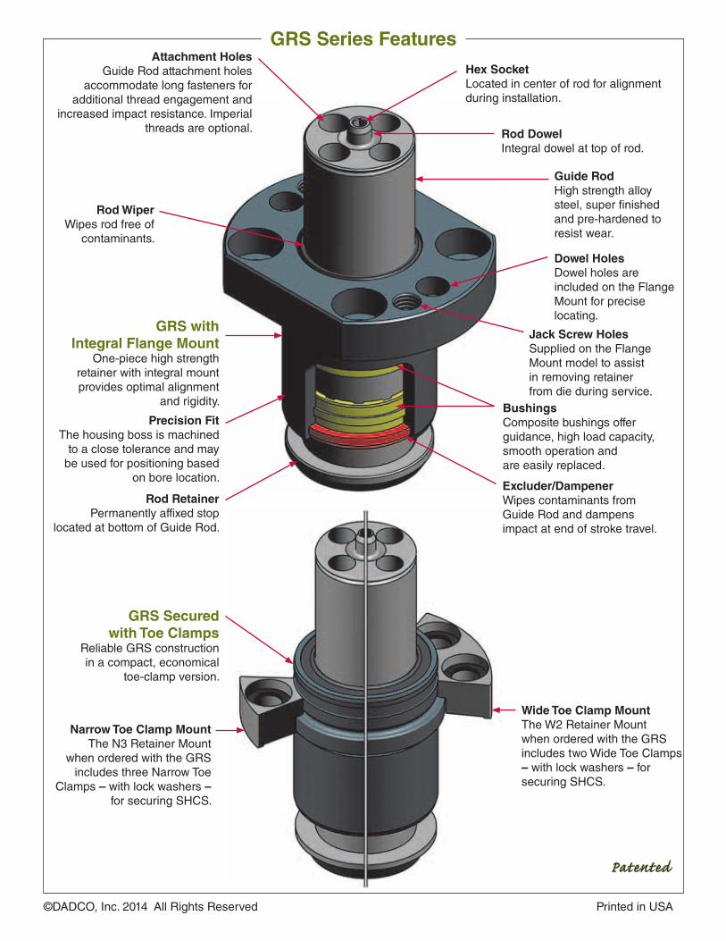
Rod DowelIntegral dowel at top of rod.
GRS with Integral Flange Mount
One-piece high strength retainer with integral mount provides optimal alignment
and rigidity.
Rod WiperWipes rod free of
contaminants.
Attachment HolesGuide Rod attachment holes
accommodate long fasteners for additional thread engagement and
increased impact resistance. Imperial threads are optional.
Guide RodHigh strength alloy steel, super finished and pre-hardened to resist wear.
Excluder/Dampener Wipes contaminants from Guide Rod and dampens impact at end of stroke travel.
BushingsComposite bushings offer guidance, high load capacity, smooth operation and are easily replaced.
Jack Screw HolesSupplied on the Flange Mount model to assist in removing retainer from die during service.
Rod RetainerPermanently affixed stop
located at bottom of Guide Rod.
Dowel HolesDowel holes are included on the Flange Mount for precise locating.
Hex SocketLocated in center of rod for alignment during installation.
GRS Secured with Toe Clamps
Reliable GRS construction in a compact, economical
toe-clamp version.
©DADCO, Inc. 2014 All Rights Reserved Printed in USA
GRS Series Features
Narrow Toe Clamp MountThe N3 Retainer Mount
when ordered with the GRS includes three Narrow Toe
Clamps – with lock washers – for securing SHCS.
Precision FitThe housing boss is machined
to a close tolerance and may be used for positioning based
on bore location.
Wide Toe Clamp MountThe W2 Retainer Mount when ordered with the GRS includes two Wide Toe Clamps – with lock washers – for securing SHCS.
Patented