G:/U l/ -/'l.IV Prolect Report No,...
61
• 7 /) - G:/U l/ .A .. -/'l.IV - 1- -/ D - r;.1C... :::J c,J r. Prolect Report No, 55 FDR CANADIAN FISHING VESSELS VOL.3 ;\.Oi:\l\.L LIEJl ':J-. V I d E . f.:.J>. 0' , , "\o,'t.) I esse s an n9lne .l:.,m9 f v ...., ,t ;' J. Industrial Developm /' ... sl'. S' Fisheries Service ... Department of the E Ottawa August 1972 • f3 • • • • • <3 • A . 4- · · () • • • • If!a. • O. • • • • • 04 • • • 4 · IJI· • • • • • ,.. • . ., . · .;;a. a· · · • • • 10
Transcript of G:/U l/ -/'l.IV Prolect Report No,...

•
7 /) -G:/U l/ .A .. -/'l.IV - 1-- / D - r;.1C...:::J ~ c,J r. Prolect Report No, 55
FDR
CANADIAN FISHING VESSELS
VOL.3
;\.Oi:\l\.L LIEJl ~~o ~
~ ~ ':J-. V I d E . f.:.J>. 0' , , "\o,'t.) I esse s an n9lne .l:.,m9 IVI~lon~ \'.~"{, f v...., ,t ;' ~o,\~~ J. Industrial Developm ~ Bran~h' ~\~"\~o,J\c<- /'
~\-« ... ",,~I'. sl'. S' ~
Fisheries Service .~ ~. o~ ~\". ... \\'.~.~. ~ ot-~ ~\s )..\~~ ~
Department of the E ~ i!~~~ Ottawa
August 1972
• f3 • • • • •
<3 • A . 4- · ·
() • •
• • If!a. • O. .~.
• • • • • 04 •
• • 4 · IJI· • • • • •
,.. •
. ., . · .;;a.
a· · ·
• • •
~.
10

/)
!
Project Report No.55
FERRO-CEMENT
FOR
FISHING VESSEL CONSTRUCTION III
Prepared by
THE BRITISH COLUMBIA RESEARCH COUNCIL
3650 WESBROOK CRESCENT
VANCOUVER 167, CANADA
for
THE VESSELS AND ENGINEERING DIVISION
INDUSTRIAL DEVELOPMENT BRANCH
FISHERIES SERVICE
ENVIRONMENT CANADA
OTTAWA, ONTARIO
August, 1972
Conclusions reached and opinions stated by the author are not necessarily endorsed by the sponsors · of this project.

Project Report No.55
All previous reports from the British Columbia
Research Council are to be found in Section 'B'
of Project Report No. 42 and in Project Report
No. 48 of The Industrial Development Branch,
Fisheries Service, Department of the Environment,
Ottawa, Ontario.
i1
•

TABLE OF CONTENTS
A. INTRODUCTION
B. SUMMARY
C. BEHAVIOUR UNDER CYCLIC BENDING STRESSES
1. Background 2. Experimental Work
(a) Apparatus (b) Tests (c) Discussion of Test Results (d) Conclusions
D. FASTENINGS
1. Background 2. Experimental Work 3. Discussion and Conclusions
E. COATINGS FOR FERRO CEMENT
1. Background 2. Experimental Work 3. Rating of Paint Systems Tested
F. CONTROL OF INTERNAL QUALITY
G. REVIEW OF LITERATURE
H. FERROCEMENT RESEARCH NEEDS
REFERENCES
BIBLIOGRAPHY
TABLES AND FIGURES
1
1
2
2 3
3 4 7 8
8
8 9
12
12
12 17 20
21
23
25
· 27
31
iii

•
•

1.
A. INTRODUCTION.
This report covers new work on Ferrocement for Canadian Fishing Vessels carried out in the 1971-72 program under the sponsorship of the Fisheries Service, Canada Department of the Environment. It has been the intent of the study over the past several years to obtain engineering data on "typical" ferrocement construction which will aid those undertaking to build a ferrocement boat. Previous studies (1,2,3) have considered the influence of several kinds of wire mesh, reinforcing rods, and mortar, on strength mainly in flexure and impact, and durability to freeze-thaw and marine exposure. A mathematical model for a steel/mortar composite was posed.
The present report looks into such areas as the behaviour of ferrocement under cyclic flexural loads and under the stress imposed by bolted fastenings, the resistance of a variety of paint coatings under various exposure conditions, and the need for control of internal quality. The literature of ferrocement and peripheral fields has also been examined. The bibliography specific to ferrocement has been maintained.
Although most of the program time has been spent directly on the tests described above, some part of the program time has been consumed in answering the many enquiries by phone, letter, and personal visits to this laboratory on the use of ferrocement construction in such applications as septic tanks and boat construction. In addition, participation in the work of the Task Group HS-6-4 Hull Structure -Ferrocement of the Society of Naval Architects and Engineers has occupied some time.
B. SUMMARY
An apparatus constructed to apply cyclic loads to beam specimens of ferrocement has provided some preliminary values for fatique strengths in flexure. Greater replication and verification is necessary to provide results which can be used with reasonable assurance. The preliminary tests indicate that the fibre stress should not exceed about 1,000 psi if a satisfactorily long service life is to be obtained in ferrocement of the kind and construction described herein.
Bolting tests on specimens of 4-inch and 8-inch wide specimens indicate that shear/bearing bolt loads in ferrocement of the kind and construction described should be tentatively limited to about 500 lb/in.

2.
A number of types of paint coatings, e.g., inorganic ethyl silicate zinc-rich paint, polyester-based, epoxy-based, polyamide resin-based, chlorinated rubber-based, and polyvinyl chloride-based paints were evaluated on the basis of visual appearance (flaking), spal1ing resistance, etc., after exposure to 600 wet/dry seawater cycles, 84 days in a tidal environment with subjection to any marine organisms present, and to 1,500 hours (6 years equivalent) in a Weather-Ometer. The inorganic ethyl silicate zinc-rich paint, the highly modified polyester resin, and a two-component pigmented epoxy resin performed best. The chlorinated rubber-based, the polyvinyl chloride-based, and two-component polyamide resin paints were judged to be good. The test results were not entirely consistent.
The potential of controlling internal quality of ferrocement composites using ultrasonic techniques is high but a considerable research program is deemed necessary to adapt present techniques to this material, especially in the uncured stage.
Newly acquired literature on ferrocement has b~en briefly reviewed and the ferrocement bibliography included in previous programs has been up-dated.
Finally, recommendations for much needed work are briefly stated.
C. BEHAVIOUR UNDER CYCLIC BENDING STRESSES.
1. Background.
The behaviour of concrete under cyclic loading has been under investigation for over 50 years. Much of the work has been concerned with repeated loading of concrete cylinders in compression and concrete beams, both reinforced and unreinforced, in bending. On the basis of early work by Clemmer (4) , 01der(5), and Hall(6) , workers generally agreed that repeated stresses higher than about 50 percent of the ultimate strength would eventually cause failure by fatigue. Stresses up to 75 percent of the modulus of rupture were considered acceptable if they were applied only a few times per year. Billig(7) discusses the general problem of the strength of concrete under repeated 10adings.as it pertains to design in structural concrete. More recent work by Hansen (8) , using sonic techniques to indicate crack initiation and propagation, showed that cracks once formed in concrete subjected to pulsating compressive loads never stabilize but continue to grow until ultimate failure.

3.
Yoshimoto et al(9) and Hilsdorf and Kesler(lO) have studied the effect of repeated loading and micro cracking on the flexural strength of concrete beam specimens. Their work shows that micro cracking can increase the flexural strength of the concrete.
The effect of cyclic stresses on the behaviour of fibrereinforced concrete has been studied to limited extent. Romualdi et al(ll), in an admittedly limited study, showed that the presence of an internal mechanism to reduce extensional stresses in the vicinity of the internal flaw edges will enhance the fatigue resistance of a concrete composite. Results of tests showed that beams containing short wire fibre reinforcement may ~have endurance limits as high as 90 to 95 percent of the static strength whereas the endurance limit of conventional concrete is about 55 percent of the static strength.
The cracking of concrete slabs reinforced with welded wire fabric with wire spacings of 3 inches or greater has also been studied (9,10).
2. Experimental Work.
(a) Apparatus. '
An apparatus was constructed to simultaneously load eight 4 x l2-inch ferrocement specimens in bending. Four pairs of rollercams attached to a central rotating shaft apply cyclic unilateral bending loads to up to four pairs of specimens at about 30 cycles per minute. The roller cams are fixed to the shaft at 45-degree intervals to load only one pair of specimens at a time thereby allowing the use of a small motor and light construction. Third-point loading of the 4 x l2-inch specimens was accomplished by means of a strain-gauged and calibrated 4-inch channel-section load cell attached to each specimen. A six-channel quick-response Visicorder monitored the applied loads. The deflection of specimens under load was measured by a dial gauge held in a saddle support over a 9-inch span. The number of load cycles applied was recorded by a cam-activated electric counter. The apparatus and load test set-up are shown in Fig. land 2. Fig. 3 shows a portion of the six-channel record of the stress.
The apparatus has the advantage of simplicity of construction and the ability to test up to four pairs of specimens at once. However, it suffers the disadvantage of being a constant-strain device rather than a constant-load device. The apparatus, after some preliminary runs, has provided some insight into the behaviour of ferrocement under repeated bending loads. Only three pairs of specimens were tested at a time because the available recorder had only six channels.

4.
(b) Tests.
(i) Run 111.
Six 4 x 12-inch specimens were prepared from Panel 53 which contained two layers of 1/2-19 gao galvanized hardware cloth above transverse 0.225 in. high-tensile double drawn rods on 2-inch centres and three layers below longitudinal rods. These specimens were used to develop loading, measuring, and recording techniques. Quantitative test results are not presented in this report. The loads were maintained at about 100 1b (a fibre stress of about 300 psi) and no specimen showed any cracking after 110,000 load cycles.
(The expression F = 2.8P may be used to determine the fibre stress for the imposed loads in this and subsequent test runs.)
(ii) Run 112.
Eight 4 x 12-inch specimens were prepared from Panel 50. This panel contained two layers of 1/2-19 gao galvanized hardware cloth above transverse 0.25 in. bright nail rods on 2-inch centres and three layers below longitudinal rods. The fibre stress at first crack and the modulus of rupture obtained from flexural testing a 12 x 24-inch specimen from this panel were 4,050 psi and 7,350 psi, respectively.
The following initial loads were applied:
Test Load Initial Initial Fibre Specimen Cell Load, 1b Stress, psi
50-1 1 500 1,400 50-2 2 500 1,400 50-3 3 750 2,100 50-4 4 750 2,100 50-5 5 1,000 2,800 50-6 6 1,000 2,800 50-7 5 900 2,550 50-8 6 900 2,550
The loading mechanism was periodically tightened to maintain a fairly constant load throughout the run but this was not an entirely successful procedure.
Specimens 50-5 and 50-6 developed fine cracks under transverse rods within 50 load cycles during the initial setting-up process. By 250 cycles, 50-6 had developed a large diagonal crack from an outside load support to a third-point load location. Spec iment unsoundness in this location undoubtedly influenced the diagonal

5.
cracking. Specimen 50-5 delaminated with a diagonal crack in a similar manner within 6,000 cycles. It was not possible to maintain the initial load on specimens 50-5 and 50-6 and they were removed from the apparatus after 6,000 load cycles. Fig. 4 and 5 show the crack condition at that time.
Specimens 50-7 and 50-8 were installed in their place and loaded to 900 lb (fibre stress = 2,550 psi). These specimens showed severe cracks before 14,000 load cycles had been applied and it was not possible to maintain a constant load. Fig. 6 shows the bottom surface before and after 100,000 load cycles.
Specimens 50-2 and 50-3 exhibited bottom cracks before 20,000 load cycles. Fig. 7 and 8 show the transverse bottom crack and the deviation towards a transverse rod as the crack progresses through the specimen.
Specimens 50-1 and 50-4 were still uncracked after 106,000 load cycles.
The loads and cycles to first observed cracking are summarized in Table 1.
(iii) Run 113.
Four specimens, 4 x 12 inches, were cut from Panel 51 which contained two layers of 1/2-19 gao galvanized hardware cloth on transverse 0.25 in. hot-rolled steel rods on 2-inch centres and three layers below longitudinal rods. The fibre stress at first crack in the static flexure test on a 12 x 24-inch specimen from this panel was 2,620 psi. The modulus of rupture at maximum load was 6,310 psi.
The specimens were inserted into the cycle testing apparatus and loaded to impose initial fibre stresses of 1,930 to 2,600 psi, Le., from about 75 to 100 percent of the maximum fibre stress at first crack obtained in static bending, as follows:
Test Load Initial Initial Fibre Specimen Cell Load, lb Stress, psi
51-3 3 760 2,130 51-4 4 930 2,600 51-5 5 710 1,990 51-6 6 690 1,930
The cyclic load apparatus was run to 200,000 cycles. The average loads over about 20 cycles and the static deflections were

6.
periodically measured during the run. The fibre stress of specimen 51-3 which developed fine cracks during initial loading leveled off at about 400 psi. The stress on the other specimens ranged from 600 to nearly 1,000 psi.
The fibre stresses in the specimen under load and the characteristic load-deflection curves are presented in Table 2 and Fig. 9.
(iv) Run 114.
Four specimens from Panel 49 (reinforced with two layers of 1/2-19 gao hardware cloth above transverse 0.225 in. high tensile double-drawn rods on 2-in. centres and three layers of 1/2-19 gao hardware cloth below longitudinal high tensile rods), one specimen from Panel 201 (containing 2 percent of steel fibre), and one from Panel 205 (containing 1 percent of steel fibre) were tested in this test run. Static bend tests on a 12 x 24-in. specimen from Panel 49 showed a fibre stress of 2,300 psi and a modulus of rupture at maximum load of 4,900 psi. The specimens were statically loaded to selected cyclic loads to calibrate the load cell and to measure the initial deflection. The specimens were then inserted into the test apparatus and loaded to the selected loads.
The following initial loads were applied:
Test Load Initial Initial Fibre Specimen Cell Load, lb Stress, psi
205-2 1 75 210 201-2 2 250 700 49-7 3 910 2,550 49-3 4 800* 2,240 49-2 5 380 1,060 49-1 6 480 1,340
(*A fine transverse crack had developed at 600 lb in static loading. )
The cyclic load apparatus was run to nearly 300,000 load cycles. The average loads over about 20-cycle increments and the static deflections of the beam specimens were determined periodically throughout the run. In this series of tests the deflections at n cycles were measured as the deflections from an initial no-load base line and from the no-load base line after n cycles. The average applied loads and deflections are presented in Table 3. Fig. 10 and 11 show how the fibre stress and deflections change with the number of imposed cycles.

7.
The specimens 201-2 (containing 2 percent steel fibre) and 205-2 (containing 1 percent steel fibre) were also tested to nearly 300,000 cycles, but at much lower loads. Specimen 201-2 was loaded to an initial fibre stress of 700 psi. Specimen 205-2 developed a crack on initial loading and was loaded only to 210 psi. The loads on the two specimens leveled off at about 600 psi and .140 psi, respectively, as shown in Table 3. The limited testing does not permit conclusions to be drawn.
The deflections, especially dynamic deflections were difficult to measure accurately and consistently. However, certain trends were observed as shown in Fig. 11. The permanent set, i.e., the "no-load" displacement of the midpoint of the beam specimen with respect to its ends at the start of the test run, n = 0, compared to the "noload" displacement after n cycles of load, increased until it reached a plateau of about 80,000 load cycles. The presence of a crack in the specimen appeared to delay the point where the permanent set became constant. The "no-load" load deflection at n = n decreased in a complementary manner until a plateau was reached after about 80,000 cycles. The total deflection from the original "base-line" is essentially constant since constant strain or deflection is characteristic of the cyclic loading machine used.
(c) Discussion of Test Results.
The results of Run #2 in which an effort was made to maintain the bending load (and fibre stress) at or near its original value indicate that the fibre stress should not exceed 1,400 psi for a reasonable fatigue life.
The results of Run #3 in which the high initial loads were allowed to decrease with time as cracks developed or as a creep mechanism (possibly microcracking) occurred indicated that fibre stresses as high as 1,000 psi could be carried for many cycles provided cracking did not occur early in the test.
Probably the most interesting results were obtained from Run #3. The load on one of the two specimens with high initial loads (greater than 2,000 psi fibre stress) decreased rapidly to about 1,000 psi fibre stress. The other, which developed an early crack, decreased to about 600 psi. However, the loads on the two specimens with only moderate initial loads (1,070 and 1,340 psi) dropped only slightly to about 1,000 psi.
The original crack in specimen 49-3 opened and closed during each loading and unloading cycle but even after nearly 300,000 cycles had an at-rest crack width of less than 0.01 in. The crack

8.
in specimen 49-3 had progressed through to the compression surface as a fine almost invisible line. The mortar was carefully chipped away from the crack at the tensile side of the specimen. All longitudinal wires in the outside layer of mesh were broken. None of the broken wires showed the elongation or ductility observed in mesh wires broken in tensile loading. The breaks in the wires are characteristic of those resulting from a fatigue mechanism.
Reinforced concrete design presupposes that the tensile strain in the concrete near the steel must exceed the extensibility of the concrete if the useful strength of the steel reinforcement is to be approached. In many applications, cracking can be tolerated. However, open cracks cannot be tolerated in corrosive environments, such as the saltwater marine environment to which ferro cement vessels are exposed. Various researchers, e.g., Nawy(12), are investigating crack control and the allowable crack width in concrete slabs reinforced with welded wire fabric in terms of crack spacing and concrete cover. The ultimate criterion of failure of ferrocement under static and repeated tensile and flexural loads is a crack which allows ingress of a corrodent and consequent deterioration of the fine reinforcement. Future work in this area would be a valuable contribution to the practical application of ferrocement to the construction of fishing vessels.
(d) Conclusions.
The tests which need greater replication and verification indicate that ferrocement specimens of the type of construction described can, in the absence of macrocracks, withstand cyclic (fatigue) fibre stresses of about 1,000 psi. Further, it is concluded that high1yloaded ferrocement can plastically deform through creep, micro cracking , or other mechanism, to diminish the bending load to a tolerable level.
D. FASTENINGS.
1. Background.
Ferrocement, in common with other "brittle" materials (arbitrarily described as those materials with failure strains less than about 5 percent), shows a considerable difference between its ultimate strength in tension and its strength in compression. The distribution of stress at a bolt hole is, therefore, quite different from that obtaining at a bolt hole in a steel plate. It follows that the practice for bolting attachments to ferrocement will differ from the practice for bolting to steel plate which, in the case of sing1eor double-bolted lap joints, are practically solved by "shop rules"

as described in various books on strength of materials and machine design.
Bolted lap joints in steel may fail from anyone of several causes: (a) shearing of the bolt, (b) tearing of the plate through the bolt holes, (c) crushing of the plate back of the bolt
9.
in bearing, (d) crushing of the bolt in bearing, (e) tearing out the plate in front of the bolt, and (f) splitting of the plate in front of the bolt. Several of these will not apply to ferrocement applications.
This report has made a preliminary study of the behaviour of ferrocement when attachments are bolted to it. The study has been confined to the case of double- and single-lap joints carrying planar loads (such as might be applied to the gunwale portion of a hull by a chain plate attachment). The relationship between the marginal pitch (the distance from the edge of the ferrocement plate to the centre of the bolt-hole) and the inter-bolt-hole spacing has been considered.
2. Experimental Work.
A series of tests was undertaken to determine the bolting characteristics of ferrocement. The tests were confined to loads parallel to the surface plane of the ferrocement test panel specimens. No tests were undertaken in which the bolts and panel were loaded normal to the panel surface, i.e., with the panel acting as a membrane. The tests provided a measure of the resistance of the ferrocement in bearing and in tensile shear.
Specimens were all cut from panels of generally similar construction. All specimens had 0.225-in. double drawn steel reinforcement (80,000 psi) on 2-in. centres in both directions and approximately the same weight of mesh reinforcement per square foot of panel area. Specimens containing 1/2-16 gao galvanized welded square mesh reinforcement contained two layers, one layer on each side of the two-layer rod reinforcement. Those containing 1/2-19 gao galvanized hardware cloth contained five layers, two layers on one side and three layers on the other side of the two-layer rod reinforcement. Those containing the 1/2-22 gao galvanized hexagonal mesh reinforcement had ten layers, five layers on each side of the two-layer rod reinforcement. All specimens were approximately one inch thick.
In the present tests, four types of ferrocement specimens were tested, these representing four bolt locations with respect to the distance from the free edge and to the distance from the free sides (in effect, the bolt spacing in a multi-bolt assembly). The four types were:

10.
Type A, 4 x 8-inch specimens with a bolt hole 2-inches from each end and each side;
Type B, 4 x l2-inch specimens with a bolt hole 4-inches from each end and 4-inches from each side;
Type C, 8 x 8-inch specimens with a bolt hole 2-inches from each end and 4 inches from each side;
Type D, 8 x l2-inch specimens with a bolt hole 4_inches from each end and each side.
Specimen types A and B approximately simulate a 4-inch bolt-hole distance between adjacent bolts and types C and D an 8-inch bolt-hole distance between adjacent bolts. All bolt holes were drilled in the centre of the space bounded by the 0.225-inch reinforcing rods on 2-inch centres. The holes were drilled through the ferrocement test specimens with a carbidetipped spade masonry drill. The bolting strength tests approximately simulate a condition such as a chain plate bolted to the hull gunwale.
Bolting of the ferrocement specimens was accomplished in the following manner:
High strength steel bolts, 1/2-inch diameter, were passed through a steel bar (5/l6-inch thick by 3-inch wide), the ferrocement specimen, a 4 x 4-inch piece of 3/4-inch fir plywood, a 1/2-inch washer, and another 5/16 x 3-inch steel bar. The assembly was tightened until the 1/2-inch washer was impressed into the fir plywood. The tensile loading mainly was transmitted to the ferrocement test specimen through the 5/16 x 3-inch steel bars in essentially a co-planar manner such as c chain plate loads would be transmitted to the hull gunwale. Sketches of the specimens and loading configurations are shown in Fig. 12.
One type A and one type B specimen (1/2-19 gao hardware cloth) were tested with the loading configuration as shown in the lower portion of Fig. 12. This set-up uses a steel bar on only one side of ~he ferrocement specimen and consequently induces higher bending stresses in the specimen. The tests are identified in Table 4 as E(A) and F(B) to indicate the modified loading configuration for specimens of types A and B.

11.
The tensile loading was applied by means of a Tinius Olsen Universal Testing ~~chine (60,000-lb capacity) using the 12,000-lb range. The maximum load held was recorded. Also, the load was recorded when a crack in line with one of the holes (either a transverse or longitudinal crack) was first observed or when a momentary dropping of the load indicator needle indicated a crack. Vertical cracks started at the end of the specimen and progressed towards the hole. The vertical cracks, although they were sometimes visible before any transverse cracks were seen, probably started after transverse cracks originating at the hole, since the transverse cracks were obscured by the steel bar until a crack had become at least an inch long.
The test results presented in Table 4 show that a hole distance of two inches from the free edge is adequate to prevent failure by edge breakout when the specimen width (bolt hole spacing) is four inches. A hole distance of four inches from the free edge is necessary to prevent edge breakout when the specimen width (bolt hole spacing) is eight inches. Fig. 13 to 16 show typical failures.
Since 4-inch wide specimen types A and B failed in a similar mode, i.e., with generally transverse cracking through one bolt hole, it is reasonable to treat the two types jointly when comparing the bolt-hole strength of specimens from 1/2-16 gao welded square mesh, 1/2-19 gao hardware cloth, and 1/2-22 gao hexagonal mesh. Since 8-inch wide type C specimens in general behaved in a different manner from type D specimens, they are treated separately.
The average maximum loads held are:
Type A, B Type C Type D
lb lb/in. lb lb/in. lb lb/in.
1/2-16 gao welded square mesh 3,350 840 4,200 525 6,000 750
1/2-19 gao hard-ware cloth 3,030 760 3,600 450 5,700 710
1/2-22 gao hexa-gonal mesh 2,570 640 3,600 450 5,200 650

12.
3. Discussion and Conclusions.
The above summary indicates that the closer bolt hole spacing (4-inch vs 8-inch) obtains higher unit loads, lb per inch of width. The load values at first visible crack, as shown in Table 4, indicate that unit loads much below the maximum loads given above will cause cracking at the hole. Since the hole crack is not visible until it has attained a crack length of at least one inch, the loads at crack initiation are only approximate and bolt loadings considerably lower than one half of the maximum loads should be used. In view of the above uncertainty, the unknown distribution of loads carried by adjacent bolts, the high possibility of a non-linear loading different from the essentially planar loading used in these tests which will induce bending stresses in the ferrocement plate, and the possible cyclic nature of the loadings it would seem unreasonable to use bolting arrangements which exert more than about 500 lb/in. in ferrocement panels of the kind and construction described herein.
E. COATINGS FOR FERROCEMENT.
1. Background.
Although history has shown that many concrete structures have failed from environmental causes, there is abundant evidence of many structures which have lasted decades and even centuries. In most natural environments well-made concrete structures do not deteriorate. The concrete (mortar) remains sound and the steel reinforcement is protected by a passivating film of iron oxide that forms in the alkaline concrete environment during placement, setting, and curing. In more aggressive environments, reinforced concrete (and ferrocement) can deteriorate from physical-chemical changes in the mortar itself or from chemical attack on the steel reinforcement. Descriptive information on the deterioration of mortar and reinforcement and on the coatings which may be applied lies chiefly in the literature of concrete structures other than ferrocement vessels. The literature provides a good understanding of the mechanisms which cause mortar deterioration and reinforcement corrosion.
(a) Deterioration of Mortar.
Concrete and mortar may fail from a number of causes. Sulphate attack is a common cause of concrete (mortar) deterioration. Sulphate attack occurs when sulphate ions in the environment react with hydrated lime and tricalcium aluminate in the cement mortar to

form a complex calcium sulfo-aluminate compound. This compound can combine with water to form crystals which increase in volume and disrupt the cement mortar. Cement Types II and V, containing low contents of tricalcium aluminate, are generally used in ferrocement work and, in general, deterioration of ferrocement by sulphate attack in a marine salt water environment should not be a serious problem. The vulnerability of concrete (mortar) to chemical attack is affected by several factors, especially the permeability of the concrete (mortar) to liquids and gases. The permeability of concretes and mortars can vary by a factor of 106 .
13.
It has been pointed out in earlier studies that disintegration of concrete by weathering is caused mainly by the disruptive action of freezing and thawing and, of course, by expansion and contraction under restraint both from temperature changes and alternate wetting and drying. The resistance of concrete and mortar to disintegration from these causes is also related to permeability and to the size distribution and shape of air voids.
Concrete and mortar may also suffer deterioration from high expansion forces exerted within the structure by corrosion products formed when steel reinforcement is attacked by corrosive agents such as salt water.
(b) Corrosion of Steel Reinforcement.
Corrosion of reinforcing steel in conrete exposed to a salt water environment is attributed (13,14) to unequal concentrations of sea salts which produce corrosion cells of the differential concentrations in the mortar result from a variable permeability - which investigators (15) have shown is the single most important physical characteristic of concrete (or cement paste) influencing the corrosion of reinforcing steel.
Oxygen is necessary for the corrosion process and it has been postulated that oxygen diffuses through the permeable concrete and establishes differential oxygen concentrations in two ways: differences in oxygen solubility in solutions of different dissolved solids content and greater availability of oxygen in those areas of lower water saturation. Variations in the dissolved solids content (salts from the seawater) of water in the capillaries in the concrete or mortar arise from wetting and evaporation which concentrate and redissolve salts in the water in the pores. The variations will be greatest at the water line and in the splash zone. Galvanic cells form with anodic areas either high salt/low oxygen or high watersaturation/low oxygen and the cathodic areas either low salt/high oxygen or low water-saturation/high oxygen. Potential differences of about 0.5 volts were found in one structure examined.

14.
The presence of salts in the pores of the cement mortar paste also has the effect of decreasing the resistivity of the mortar which results in higher galvanic currents. It has been shown that corrosion of reinforcing steel below the waterline is virtually absent. This is possibly explained by the absence of oxygen, probably permitting the establishment of a highly protective film which prevents ferrous ions passing into solution.
Steel reinforcement completely encased in normal concrete requires a minimum coverage of only 1/2 in. in most natural environments, whereas structures exposed to corrosive water environments may require a cover of 2 to 3 in. For thin concrete elements such as building panels and ferrocement boat hulls, where the encasement material is a denser mortar but where the cover provided is very thin, the reinforcement, the mortar, or both, may require a protective coating. The effectiveness of galvanized coatings on the steel reinforcement to protect the steel has been studied by many investigators(16).
(c) Coatings for Concrete (Mortar).
It is considered that coatings applied to the concrete (mortar) may act as a waterproofing membrane to prevent entry of moisture, dissolved salts and oxygen into the structure and may also provide a dielectric barrier against stray currents. However, very little recorded experience is available on the efficacy of paint in preventing corrosion of steel reinforcements in concrete structures. One investigation of 40 circular wire-wound prestressed concrete water reservoirs reported that all reservoirs showed corrosion except two that had been painted with a p'olyvinyl acetate latex coating over a flood coat of raw linseed oil(17). The unpainted tanks showed significant correlations between corrosion damage and thickness of mortar coat, wet areas, and mortar/wire bond. The investigator concludes that corrosion of stress wires may be reduced by sealing the exterior wall surface to reduce and equalize the oxygen supply to the wires. The investigator claimed that a coat of paint over mortar helps maintain equilibrium by reducing the availability of oxygen, restricting the access of positive ions, and preventing the leaching action of water. He explained that although imperfections in the coating will permit some air to reach the wire and create a local cathode area, most of the wire is anodic and the favourable ratio of anode to cathode areas makes minor imperfections of small consequence. If the cement mortar is uncoated, the wires will be in a highly cathodic state. An area where oxygen replenishment is restricted, such as a wet spot, will result in a local anode surrounded by a large local cathodic area. Accelerated corrosion at the unfavourable anode-to-cathode ratio site is likely. He

considered that a breathing type of polyvinyl acetate latex coating was satisfactory for new reservoirs but that a more impermeable coating may be required for older reservoirs where some corrosion damage and some loss of alkalinity had already occurred. He further concluded that a 3/4-inch layer of mortar is required over the wires if the reservoir is to be painted.
The only "recent" article related solely to coatings for concrete is the com1rehensive guide prepared by the American Concrete Institute in 1966 (8). The article claims that there are only 20 basic film-forming materials available for use in coatings manufacture and that these vehicles largely determine the properties and class name of coating. However, minor variations in formulations can affect the performance of the coating. The survey points out that the performance of any coating will be affected by the surface preparation, the method of application, environmental conditions at the time of application, and the film thickness.
Two up-to-date books, Technical }funual No. TM 5-618, Paints and Protective Coatings and Organic Coatings, Properties, Selection, and Uses (19,20), provide a broad survey of the many conventional and more recently developed organic coatings and a comprehensive guide to the selection and application of an adequate coating system for most materials, including concrete.
In general, oil-base paints must be avoided because the alkali in the mortar saponifies the oil-base paint unless long aging periods permit the concrete to dry out, the surface alkalinity to be neutralized, and the free, inner alkalinity to migrate out and be gradually neutralized. The limited resistance of oil-based paints, and their permeability to moisture, limits their applications in structures where moisture behind the film can cause flaking and blistering.
Latex (water-emulsion) pai~ts of the styrene-butadiene, polyvinyl acetate, and acrylic types are relatively insensitive to water and resist alkalinity well. The nature of the water-base latex paints allows application over damp (not wet) and unaged (not uncured) mortar. However, the low resistance of latex paints to corrosive environments generally restricts the use to general purpose applications.
The synthetic resin coatings which have been used successfully on concrete intended for severe service include the epoxy resins, polyesters, polyurethanes, and various synthetic rubbers. A number of other resins have shown some promise and paint manufacturers are undoubtedly investigating formulations of these and the above-mentioned types.
15.

16.
Ferrocement boat-building authorities have not put much emphasis on the need to paint ferrocement boats. Jackson and Sutherland (21) claim that painting can be eliminated if 0.05 inch of high quality mortar can be guaranteed over the steel mesh but that since plastering control is not always adequate, painting is recommended. They state that professional New Zealand practice has been to coat the outside of the hull with an epoxy resin coating to provide an additional water barrier between the sea and reinforcement near the surface and to bind any surface movement of the fine particles of sand thereby improving resistance to abrasion. They claim that anti-fouling paints are as useful for underwater sections of concrete hulls as for wood or steel hulls. Samson and Wellens (22) advise the use of two coats of thiocolbased epoxy resin to seal any stray ends of mesh, followed by antifouling paint on the hull bottom. Whitener (23) recommends that hulls for use in salt water be coated with epoxy resin finishes. He includes a list of substances which attack concrete, a list of protective treatments, and a helpful list of manufacturers of coatings and components of coatings extracted from "Effect of Various Substances on Concrete and Protective Treatments", publish(d fY the Portland Cement Association in 1968. Benford and Husen 24 offer no advice on painting.
The chief binders or vehicles which appear to have application for coating ferrocement hulls are described as follows:
(i) Inorganic binders.
Inorganic binders composed of sodium, lithium or ethyl silicates react with zinc metal dust to form very hard films which are extremely resistant to corrosion in humid or marine atmospheres. Tests have shown that zincrich paints containing high percentages of zinc dust (92-95 percent of dry film weight) afford some sacrificial anodic protection to steel until the build-up of corrosion products stifles the galvanic action.
(ii) Polyester resin-based coatings.
Polyesters are synthetic alkyd resins made by the esterification of a polyhydric alcohol with a polybasic acid. The polyester resin coating used in this study is a highly modified resin containing chlorinated paraffins and low molecular weight polystyrenes, hydraulic cement, red lead, and aluminum flake. Polyesters show considerable promise as a durable finish for concrete as well as for metal in marine environments.

17.
(iii) Vinyl resin-based coatings.
The vinyl resins include chiefly the polymers and copolymers of vinyl acetate, vinyl chlorides, and viny1idene chloride, and the polyvinyl acetates and alcohols derived from polyvinyl acetate. Polyvinyl chloride resin can be modified for use in solvent-type coatings by copolymerization with vinyl acetate. The copolymers can be formulated into solution-type air-drying coatings. The coatings have alkali resistance which makes them suitable for use over concrete and also a resistance to weather and alternate or continuous immersion in salt water which makes them suitable for marine applications. Because of their generally low solids content, vinyl finishes require several coats for adequate dry film thickness.
(tv) Epoxy-amide based coating.
The epoxy-polyamide resins are obtained by blending epoxy resins with reactive polyamide resins which act as both curing agent and modifier. Coatings from the resulting blend are reported to have good hardness, flexibility, toughness, resistance to alkali, resistance to water, and good adhesion to concrete and other surfaces. They are considered to have better resistance to continuous immersion in water than do straight epoxies. Epoxy-polyamide coatings are recommended for marine applications.
(v) Chlorinated rubber-based coatings.
Chlorinated rubber-based paints are made from chlorinated natural rubber dissolved in chlorinated aromatic hydrocarbons. The paints adhere well to concrete and provide good resistance to water and many chemicals. They have been widely used for exterior applications and for humid applications such as swimming pools.
2. Experimental Work.
(a) Preparation of Mortar Substrate.
Although the above-mentioned article and books list over fifty classes of thermoplastic and thermosetting coatings, the present study was limited to those kinds available and recommended as potentially useful by the industrial representatives of two international and national paint manufacturers.

18.
Half-panel portions of 30 x 30-in. ferrocement panels made some two years earlier were used for the application of various paint coatings. All panels had been made with Type II cement, with similar water/cement and cement/sand ratios, and with similar trowelling techniques. The wire mesh reinforcement was not the same in all panels but all reinforcement was covered with a 1/4-in. layer of mortar. The mesh pattern could be seen in the back (mould) side of all panels.
The mortar surface of the half-panels were prepared for painting as follows:
(i) The surface was ground with a flexible abrasive disc (F88SF A10xite 50 Fastcut resin disc) to smooth the surface and remove any cement film.
(ii) The surface was etched by scrubbing with 200 cc of 30 percent (or lS-percent where specified) muriatic acid until all bubbling ceased, then re-etching for 30 seconds. (Panels 13 and 14 were not etched.)
(iii) The panels were washed copiously with water and thoroughly dried at 100 F overnight.
(iv) The surface was dusted with a clean cloth before the paint was applied by brushing.
The paint coatings included an inorganic two-component self-curing ethyl silicate zinc-rich primer (as primer and top coat), a polyvinyl chloride-based enamel (as primer and top coat), a twocomponent chemica1~curing polyamide resin over a zinc-rich primer, a chlorinated rubber-based enamel, a highly modified polyester resin coat, and various top coat primer combinations. The average film thickness of all systems as measured with a calibrated microscope ranged from 4 to 6 mils.
The complete list and description of the 12 systems prepared are provided in Table 5. Exposure tests began after a 14-day cure at the normal room conditions existing in the laboratory. The original appearance of the samples is recorded in Fig. 17.
(b) Exposure Testing.
(i) Control Specimens.
Specimens of each kind were allowed to remain in the normal atmospheric environment of the laboratory for

19.
control examination. The assessment of the coatings after 4 months is presented in Table 6.
(ii) Marine Tidal Exposures.
Duplicate 3 x 3-in. specimens from the 12 panels were prepared for exposure in a marine environment subject to marine organisms. The 12 specimens, one from each pair, were set into a shallow pan of paraffin wax and enclosed in a l/2-in. mesh screen cage. The set of specimens was exposed at the Vancouver Kitsilano Station of the Canadian Coast Guard at mean tide level to give two cycles of seawater immersion and drying per day. The other specimen of each pair from the 12 panels was similarly prepared. This set of specimens was placed at the level of low low tide for complete immersion at all times. The appearance of the specimens was observed at regular intervals. The observations of the specimens after 84 days (168 tide cycles) are recorded in Table 7. The specimens exposed at mean tide and at low low tide were identical except that the former contained a slightly heavier slime coat. The appearance of the specimens before exposure and after 84 days is shown in Fig. 17 and 18.
(iii) Laboratory Seawater Exposures.
Duplicate 3 x 3-in. specimens were sawn from the 12 painted half-panels for exposure in a cyclic exposure apparatus. One of each pair of specimens was dipped in hot paraffin wax to a depth of about 5/8-in., enough to cover exposed ends of the reinforcing mesh wires. The 24 specimens set in the apparatus were subjected to 600 exposure cycles (one hour of wetting in filtered seawater and three hours of air-drying in front of an air fan). The specimens were observed at regular intervals and their appearance after 600 cycles is recorded in Table 8 and Fig. 19.
(iv) Weather-Ometer.
Duplicate 3 x 6-in. specimens were exposed in a standard Weather-Ometer apparatus. Each cycle consists of 102 min of ultraviolet light plus 18 min of ultraviolet light and water spray. The temperature is maintained at 140 F. An exposure period of 250 hr is equivalent to one year of outside mid-temperate climate. The exposure period at the time of writing was 1500 hr, equivalent to 6 years. The appearance was observed and recorded at

20.
regular intervals. Flaking of the coating in one of the specimens from panel l6B was observed after an equivalent exposure of 5 years, Fig. 20 and 21. The observations after 1500 hr (6 years) are recorded in Table 9.
3. Rating of Paint Systems Tested.
The condition of the coated specimens after 120 days in a normal indoor environment, 600 cycles of wetting and drying in a seawater cycling apparatus, after 84 days in a marine environment, and after 1500 hr (equivalent to 6 years) in the Weather-Ometer apparatus, was rated on the basis of: visual appearance (craze-cracking and flaking; ease of separating coating from.substrate with a razor blade; spall resistance to two close scores with a penknife; and resistance to gouging with a pointed probe. The composite rating was based on: Good 2, Fair 1, and Poor 0, for the four test conditions and the four evaluation tests.
The specimen-paint systems obtaining over 80 percent of the maximum points include:
Specimen No. 3A
" No. 9A
" No. 9B
" No. lIB
2 coats inorganic ethyl silicate zinc rich primer.
1 coat highly modified polyester resin containing portland cement, red lead, and aluminum flake over mortar pretreated with zinc silico-fluoride.
I coat highly modified polyester resin containing portland cement, red lead, and aluminum flake over mortar with no zinc silico-fluoride pretreatment.
2 coats two-component pigmented epoxy resin.
Those obtaining 60 to 80 percent include:
Specimen No. 7
" No. IIA
" No. 16A
1 prime and 2 top coats of chlorinated rubber-based paint.
1 prime and 2 top coats of polyvinyl chloride-based enamel.
1 prime and 1 top coat of two-component polyamide resin paint.

21.
Those obtaining 40 to 60 percent include:
Specimen No. 6
" No. l2B
" No. 14
1 clear epoxy seal coat and 2 top coats of vinyl resin anti-fouling paint.
1 coat of inorganic ethyl silicate zincrich primer and 1 top coat of polyvinyl chloride based enamel.
1 prime and 2 top coats of chlorinated rubber-based paint (no acid etch treatment).
Those obtaining less than 40 percent include:
Specimen No. l2A
" No. l6B
1 coat of inorganic ethyl silicate zincrich primer and 1 top coat of two-component polyamide resin.
1 prime and 2 top coats of chlorinated rubber-based paint.
The zinc-rich primer and metal pigmented polyester resin coatings appear to provide the best "serviceability" but these coatings have poor aesthetic chracteristics. The two-component epoxy resin, chlorinated rubber-based, polyvinyl chloride-based, and polyamide resinbased paints all appear to give reasonably good performance but the relatively poor performance of the polyamide and of another formulation of chlorinated rubber-based paint on other specimens is somewhat disconcerting. It is not known whether or not small differences in the condition of the substrate, e.g., smoothness, is responsible.
F. CONTROL OF INTERNAL QUALITY.
The preparation of specimens for the several tests in this and previous studies has exposed many internal defects in apparently sound panels. The defects are chiefly of two kinds. Unsoundness from incomplete penetration of the mortar when trowelling from both sides is probably the most serious defect. If this occurs the hollow centre of the panel fails to develop a mortar/rod bond, and the structure delaminates readily under flexural and impact stresses, greatly reducing the stiffness and strength. Unsoundness from internal gas voids is also a serious defect. Hydrogen evolves at galvanic cells set up between galvanized mesh and ungalvanized rod reinforcement in the presence of wet mortar. The gas produces voids along the ungalvanized rods which mayor may not manifest themselves in external blisters or eruptions. It has been shown that gas voids markedly reduce the mortar/rod bond strength with

22.
a resultant decrease in stiffness and modulus of rupture.
There is a great need to assess the mortared quality of vessel hulls in situ and preferably before the mortar has set. Operational control of the raw materials and conformance to cement/sand and water/ cement ratios cannot guarantee the quality of the finished product, i.e., the plastered hull. Compaction, penetration, and curing affect both the strength of the mortar and of the hull structure. Non-destructive testing must become part of any inspection and certification program.
Radiography could most usefully reveal internal defects, incomplete penetration and voids but complete radiographic inspection would be an extremely costly procedure. However, it might be used at stem, rib, and other corner sections which are difficult to penetrate with mortar.
The success attained by ultrasonics as a non-destructive tool for revealing internal defects in forgings, castings, and machinery parts suggests that it might be useful as a tool for detecting flaws in ferrocement structures. It has been used to detect flaws and to determine the strength of concrete both in massive structures and in reinforced beams although most strength tests have been performed on laboratory samples.
Special instruments have been designed for testing concrete in highways and more massive structures. One of these is a pulse flawdetector called the Betonoskop (or concrete-scope). Others are Model UCT designed by the Road Research Laboratory, Hammondsworth, Middlesex, U.K. and built by A.E. Cawkell Electronic Engineers, Southall, U.K.; a model built by Mullard Ltd. Equipment Division, London, U.K.; and Ausculteur Dynamique marketed by Laboratoire Electro-Acoustique (L.E.A.) Rueil (S. & 0.) in France.
Although ferrocement has a much finer grain size than normal concrete containing coarse aggregate, it does contain moderately coarse rods and several layers of finely divided mesh which may cause considerable scatter. Preliminary tests using an ultrasonic instrument with probes and frequencies normally used for the detection of cracks and flaws in machine parts failed to produce suitably sharp reflections.
The development of techniques for appraising the quality, both in inherent mortar strength and in structural soundness of ferrocement during plastering and after setting and curing, will require a research program of considerable size. Most standard texts on concrete discuss the use of ultrasonics in quality control. Several books(25-27) on ultrasonic testing, which provide very useful basic data on the kinds of transmitters and receivers, the use of attenuation and velocity techniques,

23.
and applicable frequencies for concrete testing procedures, can be used as an initial basis for a research program.
G. REVIEW OF LITERATURE.
Much literature has been examined during the course of this study. The literature related to the behaviour of concrete under repeated stresses and that related to paint coatings has been cited in the relevant sections.
Only a few articles on the specific subject .of ferrocement have appeared in print. Shah and Key(28) have explored the influence of different mortar compositions, yield strength of mesh, and different surface areas of reinforcement on the impact resistance of ferrocement plates. Their findings are as follows:
1. Replacement of natural sand with lightweight framed sand did not influence the tensile strength of ferrocement.
2. Increasing the ductility of steel increased the width of cracks formed under impact loads and hence the rate at which water flowed through impacted plates.
3. Superior cracking performance was obtained in tensile and impact specimens of ferrocement with reinforcement of higher specific surface.
Naaman and Shah(29) examined the influence of mesh, size, and fraction volume of reinforcement on cracking and ultimate behaviour of ferrocement specimens subjected to uniaxial tension. Their findings show the relationship between mesh parameters and crack spacing. However, the following relationships related to the "first crack" condition appear to be of greater interest for the design of ferrocement vessels:
(a) For one type of mesh, higher volumes of the mesh reinforcment showed first cracking at higher stresses.
(b) Increasing the specific surface of reinforcement increases the stress at the onset of cracking.
(c) The modulus of elasticity of the composite at first crack increases with the specific surface of the reinforcement.

24.
(d) The lower values of the modulus of elasticity at first crack can be predicted with a knowledge of moduli of mesh and the volume fraction of longitudinal reinforcement.
The width and distribution of cracking under stress has always been an important feature of ferrocement construction. Greater emphasis is being placed on the onset of cracking as a criterion of failure. Walkus(30,3l) has reported on experimental investigations into the main factors which influence the cracking and elongation of ferrocement. Other workers, already cited in another part of the report, have also considered the cracking behaviour of reinforced concrete under flexural and impact loadings.
The work by Christensen and Wi1liamson(32) has explained the galvanic cell/hydrogen evolution problem encountered by this investigation and others when fresh portland cement mortar is applied to galvanized mesh on ungalvanized (black or bright) steel rods. Christensen and Williamson found the problem of hydrogen bubble eruptions during horizontal fabrication of panels. This investigator found a serious eruption problem which required subsequent slicking and trowelling even in panels made in an upright position. The authors verified and quantized the chemical remedy of using chromium trioxide (er03) known by Bresler and Cornet and recommended(33) for the preservation of galvanized reinforcement in concrete cast against unga1vanized steel forms. They showed that Cr03 added in very dilute concentrations, 100 to 300 ppm by weight to the mix water, would prevent hydrogen evolution and increase the rod/mortar bond strength and the stiffness and ultimate strength of ferrocement in ben~ing.
Significant work especially in the mathematical analysis of ferrocement composites continues to be undertaken in universities such as Laval(34) and Sir George Williams(35).
The properties of short steel fibre-reinforced mortars continue to be examined by researchers such as Kar and Pal(36). The American Concrete Institute has recently prepared a state-of-the-art report(37) on the subject.
The use of concrete and ferrocement for offshore and und~r seas applications has been discussed by Haynes et al(38) and Shah et al{39).
Note: The bibliography of books and papers directly related to ferrocement has been maintained in a manner consistent with the listings included in previous reports on this subject for the Fisheries Service. It is consecutively numbered from that in the previous report and is located at the end of section References. All articles and books in the bibliography are on file at B.C. Research.

25 •
. H. FERROCEMENT RESEARCH NEEDS.
Many millions of dollars have been spent on studies related to the behaviour and development of the more conventional materials for hull construction. These and other studies on ferrocement have just scratched the surface of the requirements.
The development and improvement of the component parts of the ferrocement composite, i.e., mortar and reinforcement, requires much study. The study of polymer mortars and of admixtures to mortars are important areas. The possibility of using other types of steel mesh and steel rod reinforcement, of glass and other non-metallic reinforcements, and of short metallic fibres, requires much study.
The areas in which the present studies have been chiefly concerned are the engineering properties of "typical" ferrocement construction and the practical aspects of making and ensuring sound construction. Much work remains to be done, e.g.:
1. Engineering Data.
These studies have examined the behaviour of a few typical ferrocement composites under impact and bending loads and very briefly under cyclic bending. Much more work is required to obtain additional engineering data and to develop a mathematical model which will allow more general application of the determined test results to many constructions. A rational development of standardized test specimens is required. For example, the minimum length of specimen for a bend test must be determined so that the load/deflection characteristic is not affected by premature slippage of the reinforcing rods.
2. Hull Quality.
Sonic, ultrasonic, and other techniques should be studied to assess applicability as means to indicate the presence of internal air and gas pockets, incomplete penetration, and other evidence of unsoundness both in simple hull sections and at T- and Lsection joints where penetration is particularly difficult. For maximum benefit to the builder, the techniques should be able to be used before the mortar sets. Techniques for hardened mortar will aid the inspectors who must grant certification.
3. Hull Protection.
Some useful comparative data have been obtained on how various coatings resist marine environmental exposures. Work is required

to determine how well the coatings protect the mortar and reinforcement by studying:
26.
the penetration of salt water through the coating membrane under pressure, the behaviour of both mortar and reinforcement after exposure, the effect of defects, pinholes, cracks, scrapes in the coating, the effect of crack width on ingress of corrodent, galvanic attack.
A.W. Greenius Division of Engineering
411'·--1· R.4 Lake H~d, Division of Applied Physics
AWG/mc

27.
REFERENCES.
1. Kelly, A.M., and T.W. Mouat, Ferro-Cement as a Fishing Vessel Construction Material, 1968 Project Report No. 42 FerroCement for Canadian Fishing Vessels, W.G. Scott, Editor, Industrial Development Branch, Fisheries Service, Canada Department of the Environment, Ottawa, Canada, August 1971.
2. Greenius, A.W., The Development of Ferro-Cement for Fishing Vessel Construction, March 31, 1970, Project Report No. 42 Ferro-Cement for Canadian Fishing Vessels, W.G. Scott, Editor, Industrial Development Branch, Fisheries Service, Canada Department of the Environment, Ottawa, Canada, August 1971.
3. Greenius, A.W., and J.D. Smith, Ferro-Cement for Fishing Vessel Construction II, June 1, 1971, Project Report No. 48, FerroCement for Canadian Fishing Vessels, Vol 2, Industrial Development Branch, Fisheries Service, Canada Department of the Environment, Ottawa, Canada, January 1972.
4. Clemmer, H.F., The Fatigue of Concrete, A.S.T.M. Proc. Vol 22, 1922, 408-419.
5. Older, C., Highway Research in Illinois, A.S.C.E. Trans Vol LXXXVII, 1924, 1180-1224, esp.1196.
6. Hatt, W.K., Researches in Concrete, Engineering Bulletin of Purdue University 24, Nov. 1925.
7. Billig, K., Structural Concrete, MacMillan & Co. Ltd., London, 1960.
8. Hansen, T.C., Cracking and Fracture of Concrete and Cement Paste; Causes, Mechanisms, and Control of Cracking in Concrete, Publication SP-20, American Concrete Institute, Detroit, Michigan, 1968, 43-66.
9. Yoshimoto, A., S. Ogino, and M. Kawakami, Microcracking Effect on Flexural Strength of Concrete after Repeated Loading, ACI Journal Proc. Vol 69, No.4, April 1972, 233-240.
10. Hilsdorf, H.K., and C.E. Kesler, Fatigue Strength of Concrete under Varying Flexural Stresses, ACI Journal, Proc. Vol 63, No. 10, Oct. 1966, 1059-1076.
11. Romualdi, J.P., M. Ramey, and S.C. Sanday, Prevention and Control of Cracking by Use of Short Random Fibers; Causes, Mechanisms, and Control of Cracking in Concrete, Publication SP-20, American Concrete Institute, Detroit, Michigan, 1968, 179-203.

28.
12. Nawy, E.G., Crack Control in Reinforced Concrete Structures, ACI Journal, Proc. Vol 65, No. 10, Oct. 1968, 825-833.
13. Stratfull, R.F., Corrosion of Steel in a Reinforced Concrete Bridge, Corrosion, 13, (3), March 1957, l73t to l78t.
14. Stratfull, R.F., Progress Report on Inhibiting the Corrosion of Steel in a Reinforced Concrete Bridge, Corrosion 15, (6), June 1959, 33lt-334t.
15. Finley, H.F., Corrosion of Reinforcing Steel in Concrete in Marine Atmospheres, Corrosion, 17, (3), March 1961, 104t-108t.
16. Cornet, I., and B. Bresler, Corrosion of Steel and Galvanized Steel in Concrete, Materials Prot., 5, (4), April 1966, 69-72.
17. Westerback, A.E., and L.B. Hertzberg, Testing Corrosion of Reservoirs, Materials Prot., 6, (6), June 1967, 58-62.
18. Guide for the Protection of Concrete against Chemical Attack by Means of Coatings and Other Corrosion-Resistant Materials, ACI Committee 515, American Concrete Institute, J. 63(12), Dec. 1966, 1305-1391.
19. Paints and Protective Coatings. Technical Manual No. TM5-6l8, U.S. Departments of the Army, the Navy and the Airforce, Washington, D.C., January 15, 1969.
20. Organic Coatings, Properties, Selection, and Use. Building Science Series 7. U.S. Department of Commerce, National Bureau of Standards, Washington, D.C. February 1968.
21. Jackson, G.W. Jr., and W.M. Sutherland. Concrete Boatbuilding -Its Technique and Its Future. George Allen and Unwin Ltd. London, 1969.
22. Samson, J., and G. Wellens. How to Build a Ferro-Cement Boat. Samson Marine Design Enterprises Ltd., Richmond, B.C. 1968.
23. Whitener, J.R., Ferro-Cement Boat Construction, Cornell Maritime Press, Inc. Cambridge, Maryland, 1971.
24. Benford, J.R., and H. Husen. Practical Ferro-Cement Boatbuilding. Jay R. Benford, Friday Harbour, Wash. 1970.

29.
25. Ultrasonic Methods of Testing Materials, L. Filipczynski et aI, Butterworths, London, 1966.
26. Ultrasound in the Production and Inspection of Concrete, Part I: Production Applications, Yu E. Kornilovich et aI, Part II: Inspection in Hydraulic Construction, A.K. Tret'yakov et aI, Consultants Bureau, New York, 1965.
27. Ultrasonic Testing of Materials, J. and K. Krautkramer, Springer-Verlag New York Inc. 1969.
28. Shah, S.P., and W.H. Key, Jr., Impact Resistance of Ferro-Cement, J. Structural Div. Proc. American Society of Civil Engineers, Vol 98, No. STl, Jan. 1972, 111-123.
29. Naaman, A.E., and S.P. Shah, Tensile Tests of Ferro-Cement, A.C.I. Journal, Proc. Vol 68, No.9, Sept. 1971, 693-698.
30. Walkus, R., State of Cracking and Elongation of Ferrocement under Axial Tensile Load (I), Bul. Inst. polito lasi, XIV(XVIII), 3-4, 1968, 653-664.
31. Walkus, R., State of Cracking and Elongation of Ferrocement under Axial Tensile Load (II), Bul. Inst. polito Iasi, XVI (XX) , 3-4, 1970, 53-60.
32. Christensen, K.A., and R.B. Williamson, Solving the Galvanic Cell Problem in Ferro-cement, Report No. UC SESM 71-14, University of California, Berkeley, California, July 1971.
33. Galvanized Reinforcement for Concrete, A.R. Cook, Editor, International Lead Zinc Research Organization, Inc., and Zinc Institute, Inc., New York, Nov. 1970.
34. Lessard, Yves, Proprietes et Applications du Ferro-Shotcrete, Master of Science Thesis, Laval University, May 1971, pp 196.
35. Turner, D.R., An Investigation into the Tensile Strength of Ferro-Cement, Master of Engineering Thesis, Sir George Williams University, Montreal, pp 71.
36. Kar, J.N., and A.K. Pal, Strength of Fiber-Reinforced Concrete, J. Structural Division, Proc. American Society of Civil Engineers, Vol 98, ST5, May 1972, 1053-1068.
37. Fiber Reinforced Concrete - State-of-the-art Report, American Concrete Institute, Nov. 1971.

30.
38. Haynes, H.R., L.F. Kahn, and J.D. Stachiw, Concrete Hulls for Underseas Applications, J. Structural Div., American Society of Civil Engineers, Vol 91, No. ST4, April 1971. 1283-1303, and errata ibid. Vol 92, ST2, Feb. 1972, 510.
39. Shah, S.P., and W.H. Key, Jr., Ferrocement as a Material for Offshore Structures, Paper 1465, Proc. Offshore Technology Conference, Houston, Texas, April 1971.

. • (II II) II)
~ g~ (II CIC > or! ;l !1J !1J orI ~. Q S ~ ... II) ~ ec., !1J (II • (II 0 0 en • ~ rl enrl ""' ..., 4J II) ~ .D t.! r:l ,..
C en ..... Author - Affiliation Title Journal and Citation r:l rc ~ () Ci f o~ Z Eo-< QUl p..
78 Romualdi. J.P. The Static Cracking Stress The Structure of Concrete (and its behaviour x x x X K
and Fatigue Strength of under load). Proc. International Conference, Concrete Reinforced with London, Sept. 1965. A.E. Brooks and Short Pieces of Thin Steel K. Newman. edit. Wire.
79 Whitener. J.R. Ferro-Cement Boat Construc- . Book. Cornell Maritime Press, Inc., x x x x X K
tion. Cambridge, Maryland. 1971.
80 Shah. S.P •• and W.H. Key. Jr. Impact Resistance of Ferro- J. Structural Division, Proc. American x x x x X K
Cement. Society of Civil Engineers, Vol 98. No. STl, Jan. 1972. 111-123.
81 Naaman. A.E •• and S.P. Shah. Tensile Tests of Ferro-Cement J. American Concrete Institute, Proc. x x x x pc Vol 68, No. 9, Se~t. 1971, 693-698.
82 Wa1kus, R. State of Cracking and Elonga- BuI. Inst. polito Iasi, XIV(XVIII), 3-4, x x x x xx pc tion of Ferro-Cement under 1968, 653-664. Axial Tensile Load (I) •
83 " " " " (II) BuI. Inst. polito Iasi, XVI (XX) , 3-4, 1970, x x x x x 53-60.
84 Jagtianie, M.K., Gammon Concrete Boats, Barges and Journal not identified. x x x x X K India Ltd. Ships (incI. ferrocement). pp 19.
85 Kar. J.N. and A.K. Pal. Strength of Fiber-Reinforced J. Structural Division, Proc. American x x x x It Concrete. Society of Civil Engineers, Vol 98, ST5,
May 1972 1053-1068.
86 Shah, S.P., and B.V. Rangan. Fiber Reinforced Concrete J. American Concrete Institute, Proc. Vol 68 , x x x x pc Properties. No. 2, Feb. 1971, 126-135.
87 Lessard. Y. Proprietes et Applications Master of Science Thesis, Faculty o~ Scienc~ x x x x x pc "du Ferro-Shotcrete. Laval University, Montreal, Ma~ 1971, pp 197.

. • QI II) II) II) u
~ QI ~ et c:: > ~ cu cu
oM "" Q ~ ~ .... til cu QI QI 0 0 til • ~ .-t ; .-t ""' .... .... til
Author - Affiliation Title Journal and Citation ~ .0 I'Cl ~ 0 Ill .... cu cu ~ u CJ If: ~h~ z E-< Q U) p..
88 Turner. D.R. An Investigation into the Master of Engineering Thesis. Sir George x x x x x x Tensile Strength of Ferro- Williams University. Montreal. pp 71-Cement.
89 American Concrete Institute Fiber Reinforced Concrete - American Concrete Institute. Nov. 1971. x x x x IX Committee 544. State-of-the-art Report. pp 56, mimeo.

33.
TABLE 1. LOAD AND FIBRE STRESS IN BEAMS FROM PANEL 50 IN REPEATED BENDING
Approximate Bending Load
Specimen Load Fibre Stress No. 1b psi No. of Cycles to First Observed Crack
50-1 500 1400 Not broken after 106,000 cycles.
2 500 1400 >12,000 <20,000
3 750 2100 >12,000 <20,000
4 750 2100 Not broken after 106,000 cycles.
5 1000 2800 <50
6 1000 2800 <50
7 900 2500 >6,000 <14,000
8 900 2500 >6,000 <14,000
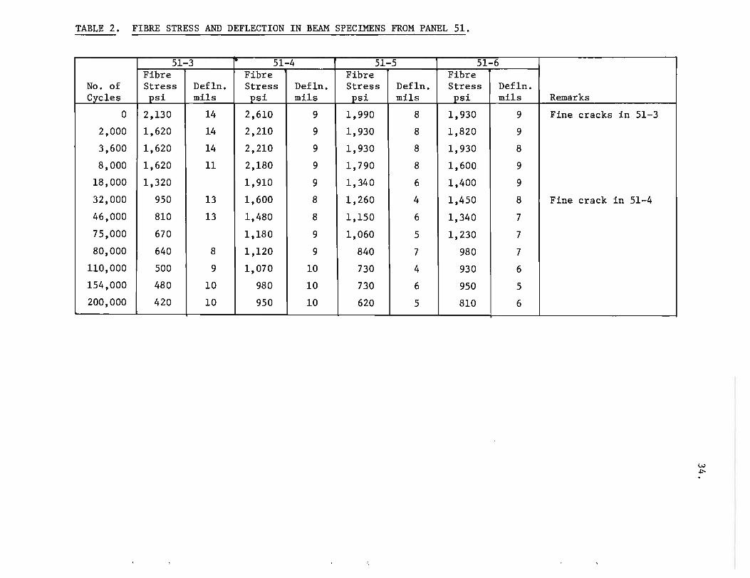
TABLE 2. FIBRE STRESS AND DEFLECTION IN BEAM SPECIMENS FROM PANEL 51.
51-3 51-4 51-5 51-6 Fibre Fibre Fibre Fibre
No. of Stress DefIn. Stress DefIn. Stress DefIn. Stress DefIn. Cycles psi mils psi mils psi mils psi mils Remarks
0 2,130 14 2,610 9 1,990 8 1,930 9 Fine cracks in 51-3
2,000 1,620 14 2,210 9 1,930 8 1,820 9
3,600 1,620 14 2,210 9 1,930 8 1,930 8
8,000 1,620 11 2,180 9 1,790 8 1,600 9
18,000 1,320 1,910 9 1,340 6 1,400 9
32,000 950 13 1,600 8 1,260 4 1,450 8 Fine crack in 51-4
46,000 810 13 1,480 8 1,150 6 1,340 7
75,000 670 1,180 9 1,060 5 1,230 7
80,000 640 8 1,120 9 840 7 980 7
110,000 500 9 1,070 10 730 4 930 6
154,000 480 10 980 10 730 6 950 5 ~
200,000 420 10 950 10 620 5 810 6

TABLE 3. FIBRE STRESS AND DEFLECTION IN BEAM SPECIMENS FROM PANELS 205, 201, AND 49.
205-2 201-2 49-7 49-3 49-2 Fibre Fibre Fibre Fibre Fibre
No. of Stress Defln. Stress Defln. Stress Defln. Stress Defln. Stress Def1n. Cycles psi mils psi mils psi mils psi mils psi mils
0 210 700 2550 2240 1070
3,600 140 590 2120 1900 870
9,200 140 19 640 3 1940 12 1850 13 1000 5
26,000 140 18 620 3 1400 12 980 13 950 4
38,000 140 620 1180 760 980
44,000 140 630 1320 840 920
64,000 140 18 640 3 1200 8 760 11 920 5
94,000 140 22 590 3 1150 8 790 11 670 5
120,000 140 22 630 3 1200 7 730 11 840 5
150,000 140 16 590 3 1120 10 640 10 840 5
170,000 140 16 590 3 1000 9 590 11 840 4 200,000 140 17 590 3 960 10 560 11 840 5 250,000 140 24 590 3 1040 10 560 12 840 5 280,000 140 15 560 3 1120 5 640 11 810 6
49-1 Fibre Stress Def1n. psi mils
1340
950
1280 7
1340 5
1250
1120
1200 6
1160 5
840 4
1060 3
920 4
870 6
1000 4
1060 7
W In

36.
TABLE 4. RESULTS OF BOLTING TESTS.
(single 1/2-in. bolts in 4-in. wide (A,B) and 8-in. wide (C,D) specimens)
Panel Construction Specimen Load at First Uax. load Mode of Failure Type Visible Crack, lb held, lb
1/2-16 ga welded A (2400) 3300 transverse, vertical square mesh B 2600 2800 transverse (2 layers) B (2800) 3400 transverse
B 3000 3900 transverse C 3600 4200 vertical, transverse D 4100 6000 transverse, vertical
1/2-19 ga hardware A (2200) 2700 transverse, vertical cloth A 2800 3300 transverse (5 layers) A (2300) 2750 transverse
A 2100 2600 transverse B 2800 3200 transverse B (2600) 2800 transverse B (3000) 3850 transverse C (3200) 3600 vertical, transverse C 3300 3600 vertical, transverse D (5100) 6000 transverse, vertical D 5000 5400 transverse, vertical E(A) 1600 2630 transverse F(B) 1500 2450 transverse
1/2-22 ga hexagonal A* 800* 1200* transverse mesh A (2000) 2600 transverse vertical
B (1700) 2500 transverse B 1800 2600 transverse C 3000 3600 transverse, vertical D 4000 5200 transverse, vertical
* tensile loading transverse to direction of mesh.

HalfPanel No.
3A
6
7
9A
9B
llA
llB
Etched in
HCl
Yes
Yes
Yes
Yes
Yes
Yes
Yes
TABLE 5. PAINT SYSTEMS EXPOSED
Descri~tion of Paint ~stem Used
Primer - Inorganic two-component self-curing ethyl silicate zinc-rich primer. Dried 6 hr in normal laboratory environment.
Top coat - same as primer coat.
Primer seal coat - Two-component clear epoxy finish. Dried 8 hr in normal laboratory environment.
Top coats - vinyl resin base anti-fouling paint. Dried 4 hr. - vinyl resin base anti-fouling paint.
Primer seal coat-Chlorinated rubber-based paint thinned with 15 percent thinner. Dried 8 hr. Top coats - Chlorinated rubber-based paint.
- Chlorinated rubber-based paint.
Primer seal coat - Zinc si1ico-fluoride solution. Dried 16 hr. Top coat - Steelmate* - a highly-modified polyester resin vehicle containing metal and metallic
oxide fillers.
Primer seal coat - None. Top coat - Stee1mate (as in 9A).
Primer seal coat - Polyvinyl chloride-based enamel coating thinner with IS-percent vinyl thinner. Dried 2 1/2 hr.
Top coats - Polyvinyl chloride-based enamel. Dried 2 1/2 hr. - Polyvinyl chloride-based enamel coating.
Primer seal coat - None. Top coats - Two-component pigmented epoxy-resin coating. Dried 5 1/2 hr.
- Two-component pigmented epoxy~resin coating.
*Steelmate is a proprietary formulation of B.C. Research developed especially for underwater application on steel.
Total Coating Thickness
mils
6
4
4
4
4
5
4

TABLE '5.
HalfPanel lNo.
12A
12B
13
14
16A
l6B
(cont'd) •
Etched in
HCl
Yes
Yes
No.
No
Yes
Yes
Descri~tion of Paint System Used
Primer seal coat - Inorganic two-component self-curing ethyl silicate zinc-rich primer. Dried 6 hr.
Top coat - Two-component clear chemical curing polyamide resin.
Primer seal coat - Inorganic two-component self-curing ethyl silicate zinc-rich primer. Dried 6 hr.
Top coat - Polyvinyl chloride-based enamel thinned with 30-percent vinyl thinner.
Primer seal coat) - As in panel No.6. However top coats broke badly and specimens were Top coats ) not exposed to environment tests.
Primer seal coat) -) - As in panel No.7. Top coats
Primer seal coat - Clear chemical curing polyamide resin. Dried 24 hr. Top coat - Two-component clear chemical curing polyamide resin.
Primer seal coat - Chlorinated rubber-based enamel thinned with IS-percent compatible thinner. Dried 24 hr.
Top coats - Chlorinated rubber-based enamel. Dried 24 hr. - Chlorinated rubber-based enamel.
Total Coating Thickness
mils
6
6
4
5
4

TABLE 6.
Specimen No. Visual A~~earance
3 Fine crazing.
6 No defects.
7 " "
9A " " 9B " "
llA " "
llB " "
l2A " " l2B " "
14 " "
l6A " "
l6B " "
ASSESSMENT OF COATINGS AFTER 4 MONTHS IN ROOM ENVIRONMENT (not exposed to weather or service environment)
Separation Resistance (Liftin~ with razor blade)
Separates easily. Brittle flakes.
No separation at interfaces.
No separation at interfaces.
No separation at interfaces.
No separation at interface.
Separates with difficulty.
Separates with difficulty.
Spall Resistance (Scoring with penknife)
Spalls and crumbles.
Spalls.
No spalling.
No spalling.
No spalling. Debris tenacious.
No spalling. Debris tenacious.
No spalling. Debris tenacious.
Separates fairly easily. Brittle. Spalling. Debris tenacious.
Top coat separates from primer. Tough.
Separates with difficulty.
Separates with difficulty.
Top coat separates from primer. Brittle.
Spalls. Debris tenacious.
Spalls slightly.
No spalling. Debris tenacious.
Spalling. Debris brittle.
Gouge Resistance (Pointed tool)
Fair
Fair
Good
Good
Good
Good
Good
Good
Fair
Fair.
Good
Poor

Specimen No.
3
6
7
9A
9B
llA
llB
l2A
l2B
14
il6A
rL6B
Visual Appearance
TABLE 7. ASSESSHENT OF COATINGS AFTER 84 DAYS MARINE EXPOSIIRE AT MEAN TIDE
(Vancouver - Kitsilano)
Separation Resistance (Liftin~ with razor blade)
Spall Resistance (Scoring with 1)enknife)
Slime layer - otherwise No separation at interface. Slight spalling. Debris crumbly. clean as original.
. II
II
"
"
II
..
.. II
II
" II
Spalls with difficulty.
No separation at interface.
II
"
Separates as tough film.
Separates only with difficulty.
Spalls at interface.
Top coat separates from primer as tough film.
No separation.
Spalls readily.
" II
Spalls. Debris slightly crumbly.
No spalling. Debris slightly crumbly.
" Slight spalling. Debris slightly crumbly.
Slight separation. Debris tenacious •
II
Spalls fairly readily.
Spalls fairly readily. Debris crumbly.
Slight separation. Debris tenacious.
Spalls readily.
II "
Gouge Resistance (Pointed tool)
Good
Fair
Good
"
"
Good
"
" Fair
Fair
Good
Poor

Specimen lNo. Visual Appearance
3 Heavy brown bloom. No surface defects.
6 No surface defects. 'Yellow stain.*
7 II "
9A " " 9B " "
~1A " "
~IB " "
12A " " 12B Coating lifted at one
corner.
14 No surface defects.
16A " " " l6B " " "
TABLE 8. ASSESSMENT OF COATINGS AFTER 600 CYCLES IN SEAWATER (1 hr immersed - 3 hr drying in moving air)
Separation Resistance (Liftin2 with razor blade)
No separation at interfaces.
No separation at interfaces.
No separation at interface.
No separation at interface.
No separation at interface.
Easy separation at mortar interface.
Separates with difficulty.
Spall Resistance (Scoring with penknife)
No spalling. Debris crumbly.
Spalls. Debris slightly crumbly.
No spalling. Debris slightly crumbly.
No spalling. Debris tenacious.
No spalling. Debris tenacious.
Spalling. Debris tenacious.
No spalling. Debris tenacious.
Separates fairly easily. Brittle. Spalling. Debris tenacious.
Gouge Resistance (Pointed tool)
Good
Fair
Fair
Fair
Fair
Fair
Fair
Fair
Top coat separates from primer as No spalling. Debris tenacious. Poor tough film.
Separates with difficulty. Spalls slightly. Debris tenacious. Poor
Separates with difficulty. No spalling. Debris tenacious. Fair
Top coat separates from primer. Spalling. Debris brittle. Poor - spalla.
*All specimens exhibited yellow staining.

TABLE 9. ASSESSMENT OF COATINGS AFTER 1500 HR (6 YR) IN WEATHER-OMETER
Specimen No. Visual Appearance
3
6
7
9A
9B
llA
llB
l2A
l2B
14
l6A
l6B
Fine craze cracking. Yellow encrustation.
Fine craze cracking. Yellow stain.*
Fine craze cracking and flaking.
Fine craze cracking. Clean surface.
Fine craze cracking. Clean surface.
Good surface.
Good surface.
Fine craze cracking.
A few craze cracks
Fine craze cracking and flaking.
A few fine craze cracks.
Craze cracking, curling, film loss.
Separation Resistance (Liftin~ with razor blade)
No separation at interface.
Separates cleanly from interface but with difficulty.
Separates eaSily and cleanly at interface.
No separation at interface.
No separation at interface.
Separates readily at interface in continuous film.
Separates only with difficulty.
Separates readily at interface with spalling.
No separation at interface.
Separates easily and cleanly at interface.
Separates easily and cleanly at interface.
Spall Resistance (Scorin~ with penknife)
No spalling. Debris crumbly.
Spalls cleanly in flakes.
Spalls easily and cleanly.
Spalls slightly. Debris flaking and crumbly.
Spalls slightly. Debris flaking and crumbly.
No spalling. Tough film.
No spalling. Tough film.
Spalls easily and cleanly.
Spalls slightly. Debris crumbly.
Spalls easily and cleanly.
No spalling. Tough film.
Separates cleanly with difficulty Spalls easily and cleanly. at interface.
*All specimens except 9A and 9B exhibited yellow stain.
Gouge Resistance (Pointed tool)
Good
Fair
Poor
Fair
Fair
Good
Good
Fair
Fair
Poor
Good
Poor

Fig. 1. Cyclic flexure test apparatus and recorder.
Fig. 2.
Beam specimens and load cells in cyclic flexure test apparatus.

Fig. 3. Load-cell readout for six flexure beam specimens.

Fig. 4. Specimen 50-6 before and after 6000 cycles of bending loads.

Fig. 5. Diagonal crack in specimen 50-5 between outside load support and third point loading.

.. r~ f ' '-, _jb ~""r , ,... -~,
. . .... ----- " -, ')"'
I
Fig. 6. Specimen 50-8 before and after 100,000 cycles of bending loads.
I

A t 'I' . .. _ & 1~ . , i .1iI ~ I
Figs. 7 and 8. Bottom crack in specimen 50-2 and deviation towards transverse rod.

- -----
3000~--------------------------------------------------'
..-4
~OOO
~1000 ~ ~
------- 51-4 ~------- 51-6 ------_51-5
--------51-3
0L-------~ ______ ~ ______ ~ ______ _L ______ ~ ______ ~
.. al al GI 101
3000
2000
~ 1000 GI 101
~ ~
100,000 200,000 Number of Load Cycles
Fig. 9. Characteristic fibre stress curves for beams from panel 51 under repeated beriding.
49-7
49-49-2
49-3
oL-______ ~ ______ ~ ______ ~ ______ ~~ ______ ~ ____ ~
100,000 200,000 Number of Load Cycles
Fig. 10. Characteristic fibre stress curves for beams from panel 49 under repeated bending.
300,000

20
(Cyclic component of deflection)
10 "~ 49-3
49-7 "-~ -..:::::::::: 49-2
49-1
° l I I I I
. ~
..-I
r-I 0 0 .
40 0
.. ~ 0
..-I ~ tJ CI)
49-3 r-I ~
CI) 30 c:::I
~ CI) ~
(Permanent set component of deflection) 20
49-1
49-7
10 r-49-_
2 ---
° ~--------~--------~--------~--------~--------~--------~ ° 100,000 200,000 300,000
Number of Load Cycles
Fig. 11. Characteristic deflection curves for beams from panel 29 under repeated bending loads.

,---.---.----.. --...... ----.---.... -.. -.---.----.. -.----.--------... -- .. --_···_··_· __ ····-----·1 ! . j!1 : ~ ~ I
, .~ .. --
+ - -
10
~I
L
~"~4 I, ' d t 1
r" r
rr. L!
n ! tr:~"J. I ' , I ' . ~ :
4 ! I .
, :]1
A
B
r--! 0 ,
Li : . . !-
_.- -i .. -:---'1 ; ! i ! , i '"l J' i I , . I i L.-.-- .
1 = ...:: =- - . , r---< ,
L' ! c, i. ;
,! : -.--...... - - . i--·_·
-'-~-I-! .--I
I ,- ,
,l:·tl I,' ' . I , i 0 , , ,_.J I L - .- . - ! i :-i - '~I - : I ~! () I i ! I I r ! i ,_ ~ ~ l ;
i
..,1
,.l..,
L
I;':
n1 1 ~" :1 : 11 : : ~'
., j. 1;
r, , I ' !
~
D
~ L __ ~j I" i . .1 " '- .. -' ,\, . ---------------------- .. -- - ---- ..... -, -- f
t r
o
';:
'!>;
-+---l ~- I
J .. l
---o
!
1 i
' i
E(Aj
, f '---. . t i i
L .... i . ... __ ..... _ .. _ ... ___ ......... _ ........ _ .... _j .. _
F ,...,\ I
rk', ; \"-"1 ,
,
,_._ --' Fig. 12. Loading geometry for specimen types At B, C. and D (approximately
coplanar) and for specimen types E(A} ana FtB} (offset).

B •
. ' . . " ... ," . .., . " ... . ' .
Fig. 13.
Bolting failure in Type A specimens.
Fig. 14.
Bolting failure in Type B specimens •

c
•
, "
4 ' ••• ~
,"
....... ... . ,
.~. "; '. ,..
Fig. 15.
Bolting failure in Type C specimens •
Fig. 16.
Bolting failure in Type D specimens.

•
Fig. 17. Original appearance of painted ferrocement specimens (use code of Fig. 18 and Table 5 to identify) •
Fig. 18. Appearance of specimens after 84 days marine exposure at mean tide. Slime coat partly removed.

•
•
•
•
Fig. 19. Appearance of specimens after 600 wet/dry cycles in a laboratory tank of seawater.

..
Figs. 20 and 21.
Specimens removed from Weather-Ometer after 1500 hrs exposure •