
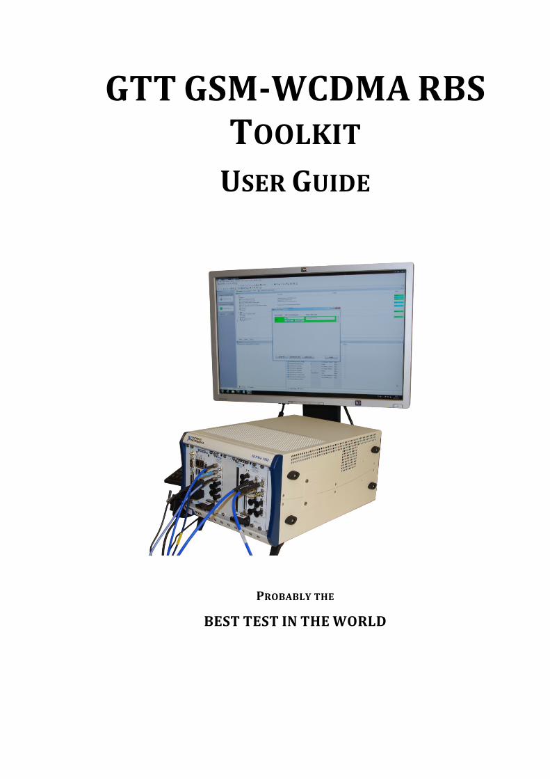
GTT GSM-WCDMA RBS TOOLKITThe GTT GSM-WCDMA RBS Toolkit is built around a NI PXIe chassis and NI...
31
GTT GSM-WCDMA RBS TOOLKIT USER GUIDE PROBABLY THE BEST TEST IN THE WORLD
Transcript of GTT GSM-WCDMA RBS TOOLKITThe GTT GSM-WCDMA RBS Toolkit is built around a NI PXIe chassis and NI...
GTTGSM-WCDMARBSTOOLKITUSERGUIDE
PROBABLYTHE
BESTTESTINTHEWORLD

GTTGSM-WCDMARBStoolkit–UserGuide522A1-SP03003-1V1.0.02018-08-02 2
Copyright © 2018 Gefle Testteknik AB. All rights reserved. Under the copyright laws, this publication may not be reproduced or transmitted in any form, electronic or mechanical, including photocopying, recording, storing in an information retrieval system, or translating, in whole or in part, without the prior written consent of Gefle Testteknik AB. Note:
GTTGSM-WCDMARBStoolkit–UserGuide522A1-SP03003-1V1.0.02018-08-02 3
The GSM/EDGE Signal Generation Toolkit, the NI WCDMA/HSPA + Measurement Suite, which are incorporated into the GTT GSM-WCDMA RBS Toolkit, are the property of National Instruments Corporation. Copyright © 2014 National Instruments Corporation. All Rights Reserved.
GEFLETESTTEKNIKRESPECTSTHEINTELLECTUALPROPERTYOFOTHERS,ANDWEASKOURUSERSTODOTHESAME.GEFLETESTTEKNIKISPROTECTEDBYCOPYRIGHTANDOTHERINTELLECTUALPROPERTYLAWS.
1 INTRODUCTION.......................................................................................................................................................51.1 GTTGSMRBSTOOLKIT.................................................................................................................................................5
1.2 GTTWCDMARBSTOOLKIT...........................................................................................................................................5
1.3 GTTGSM-WCDMADLBERADD-ON.............................................................................................................................6
2 SYSTEMREQUIREMENTS.........................................................................................................................................6
3 INSTALLATIONANDCONFIGURATION......................................................................................................................63.1 GSM&WCDMARBSTOOLKIT......................................................................................................................................6
4 EVALUATION/ACTIVATION......................................................................................................................................74.1 EVALUATION/ACTIVATION................................................................................................................................................7
4.1.1 Evaluation...........................................................................................................................................................7
4.1.2 Onlineactivation.................................................................................................................................................8
4.1.3 Offlineactivation................................................................................................................................................8
5 USINGTHETOOLKITS...............................................................................................................................................85.1 GTTGSMRBSTOOLKIT.................................................................................................................................................8
5.1.1 GenerationSoftFrontPanel...............................................................................................................................8
5.1.2 Measurementdefinitionsaccordingto3GPP...................................................................................................15
5.2 GTTWCDMARBSTOOLKIT.........................................................................................................................................16
5.2.1 GenerationSoftFrontPanel.............................................................................................................................16
5.2.2 AnalysisSoftFrontPanel..................................................................................................................................20
5.2.3 Measurementdefinitionsaccordingto3GPP...................................................................................................23
6 CONTACTINFORMATION.......................................................................................................................................25
7 ABBREVIATIONS....................................................................................................................................................25
8 REFERENCES..........................................................................................................................................................27
APPENDIXA-3GPP VERSIONS FOR GSM MEASUREMENTS.............................................................................27
APPENDIXB-3GPP VERSIONS FOR WCDMA MEASUREMENTS.......................................................................27
APPENDIXC..................................................................................................................................................................28GSM...................................................................................................................................................................................28

GTTGSM-WCDMARBStoolkit–UserGuide522A1-SP03003-1V1.0.02018-08-02 4
WCDMA.............................................................................................................................................................................29
GTTGSM-WCDMARBStoolkit–UserGuide522A1-SP03003-1V1.0.02018-08-02 5
1 Introduction
The GTT GSM-WCDMA RBS Toolkit is a software-suite for anyone looking for the most efficient usage of National Instruments RF-test hardware for testing RBS related products. GTT has created a versatile product suite that will help the users with everything from early verification to full scale production testing. It gives You as a customer the starting point you need for your test setup. GTT can of course assist you with optimization for your specific application. The GTT GSM-WCDMA RBS Toolkit is built around a NI PXIe chassis and NI LabVIEW. It consists of NI LabVIEW toolkits for generating and analysing GSM and WCDMA DL signals. It also supports NI RFSA and RFSG.
The two covered standards are in the code separate but can be used simultaneously.
The capabilities of GTT toolkits can be expanded with Add-ons. To run the Add-ons a licensed installation of the base toolkit is required. Se below for details on available Add-Ons.
1.1 GTTGSMRBSToolkit
The GTT GSM RBS toolkit supports both generation and analysis of a GSM signals. Besides the capability of analysing the downlink signal and generating uplink for receiver testing, the toolkit also comes with signal generation of downlink for calibration and/or verification of the setup without a UUT. The user frequency band can be set for the generated signal. The following measurements are supported by the toolkit:
- Modulation Accuracy
- Transmit Power
- Output RF Spectrum
- Power Versus Time
A more detailed description of the measurements is to be found in ref [1]. For supported 3GPP revisions, see appendix A.
1.2 GTTWCDMARBSToolkit
The GTT WCDMA RBS toolkit supports both generation and analysis of WCDMA signals. Besides the capability of analysing the downlink signal and generating a 12.2 kbps uplink signal (TC1)for receiver testing, the toolkit also comes with signal generation of downlink signal according to test model (TM) 1, 2, 5 and 6 for calibration and/or verification of the setup without a UUT. The following measurements are supported by the toolkit:
- Base station Output Power
- Error Vector Magnitude (EVM)
- Frequency Error
- CPICH Power Accuracy
- Adjacent Channel Leakage Power Ratio (ACLR)
GTTGSM-WCDMARBStoolkit–UserGuide522A1-SP03003-1V1.0.02018-08-02 6
- Occupied Bandwidth (OBW)
- Spectrum Emission Mask (SEM)
- Peak Code Domain Error
- Relative Code Domain Error (CDR)
A more detailed description of the measurements is to be found in ref [2]. For supported 3GPP revisions, see appendix B.
1.3 GTTGSM-WCDMADLBERAdd-on
The GTT GSM-WCDMA DL BER Add-on by Gefle Testteknik AB features demodulation of GSM signals to enable verification of RBS transmitter system performance using analysis of throughput in form of BER (Bit Error Rate) and BLER/FER (Block Error Rate for WCDMA/Frame Error Rate for GSM).
The included soft front panels enable easy lab measurements and the high-level APIs makes custom sequences or fully customized soft front panels easy to make.
For details on this add-on refer to the user manual for GTT GSM-WCDMA DL BER-BLER Add-on Ref [5]
2 SystemRequirements
See http://testteknik.se/content/product for a list of software and hardware requirements for the different products.
3 InstallationandConfiguration
3.1 GSM&WCDMARBSToolkit
Start LabVIEW and VIPM with administrator rights and start the installation of the “GSM WCDMA RBS” using VIPM 2014 or newer.
The installed SFPs are by default located at:
32-bit Windows: C:\Program Files\Gefle Testteknik\GSMRBS 64-bit Windows: C:\Program Files (x86)\Gefle Testteknik\GSMRBS 32-bit Windows: C:\Program Files\Gefle Testteknik\WCDMARBS 64-bit Windows: C:\Program Files (x86)\Gefle Testteknik\WCDMARBS
The installed APIs are by default located at:
…\National Instruments\LabVIEW 2012\vi.lib\GefleTestteknik\GSMRBS\... …\National Instruments\LabVIEW 2012\vi.lib\GefleTestteknik\WCDMARBS\...
GTTGSM-WCDMARBStoolkit–UserGuide522A1-SP03003-1V1.0.02018-08-02 7
4 Evaluation/Activation
The distributed executables and the GTT LabVIEW libraries (*.lvlib) are licensed and have an evaluation period of 30 days and must then be activated for continued use. The license is locked to the computer that is used during installation.
We recommend using GTT licensing toolkit for activation of licenses. The built-in activation tool in Labview may also be used.
To transfer a license, it must first be deactivated on the system where it is currently active before activation on the new system. When restoring the computer from a backup image deactivation must be performed before deleting the old system.
A product can be manually activated (i.e. offline) by sending an email to [email protected] in the following format. NOTE that manually activated licenses cannot be deactivated or transferred:
Company Name: User Name: Executable User Code 1: Executable User Code 2: LabVIEW Library User Code 1: LabVIEW Library User Code 2:
For further information refer to the preferred tool for activation.
See more information below.
The evaluation/activation process is different depending on which product and version that is used.
4.1 Evaluation/Activation
Selection of Activation/Evaluation mode of the LabVIEW libraries and the executable is done from a “Third Party Add-ons” dialog box inside LabVIEW. This one is shown automatically when LabVIEW is started and can also be reached from following menu inside LabVIEW: Help -> Activate Add-ons.
4.1.1 Evaluation
If Evaluation mode is wanted, no particular action is necessary. Simply click “Continue to LabVIEW”.
GTTGSM-WCDMARBStoolkit–UserGuide522A1-SP03003-1V1.0.02018-08-02 8
4.1.2 Onlineactivation
Open the “Third Party Add-ons” dialog box inside LabVIEW and select “Activate Add-ons”. In the next dialog box, select the GTT toolkit you wish to activate and press “Next”. In the next Dialog box, select “Automatically activate through an Internet connection” and press “Next”. In the next dialog box enter the LicenseID and password you got when you bought the product and press “Activate”.
4.1.3 Offlineactivation
Open the “Third Party Add-ons” dialog box inside LabVIEW and select “Activate Add-ons”. In the next dialog box, select the GTT toolkit you wish to activate and press “Next”. In the next Dialog box, select “Use a Web browser on this or another computer to acquire an activation code” and press “Next”. In the next dialog box, send these two “LabVIEW User Codes” to [email protected], using the mail template above. GTT will send back two activation codes. Copy these two into the Activation Code 1 and 2 and press “Activate”.
5 UsingTheToolkits
5.1 GTTGSMRBStoolkit
5.1.1 GenerationSoftFrontPanel
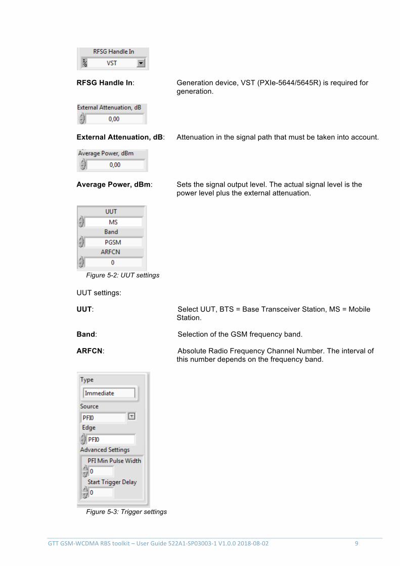
The soft front panel for GSM signal generation is started from Windows Start -> Program -> Gefle Testteknik -> GSMRBS -> GSMRBSGen.
The generation window appears:
Figure 5-1: the GSM signal generation front panel
There are a number of settings for the signal generation:
GTTGSM-WCDMARBStoolkit–UserGuide522A1-SP03003-1V1.0.02018-08-02 9
RFSG Handle In: Generation device, VST (PXIe-5644/5645R) is required for generation.
External Attenuation, dB: Attenuation in the signal path that must be taken into account.
Average Power, dBm: Sets the signal output level. The actual signal level is the power level plus the external attenuation.
Figure 5-2: UUT settings
UUT settings:
UUT: Select UUT, BTS = Base Transceiver Station, MS = Mobile Station.
Band: Selection of the GSM frequency band.
ARFCN: Absolute Radio Frequency Channel Number. The interval of this number depends on the frequency band.
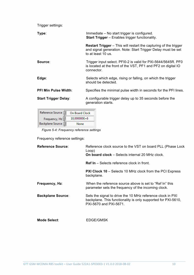
Figure 5-3: Trigger settings
GTTGSM-WCDMARBStoolkit–UserGuide522A1-SP03003-1V1.0.02018-08-02 10
Trigger settings:
Type: Immediate – No start trigger is configured. Start Trigger – Enables trigger functionality.
Restart Trigger – This will restart the capturing of the trigger and signal generation. Note: Start Trigger Delay must be set to at least 10 us.
Source: Trigger input select. PFI0-2 is valid for PXI-5644/5645R. PF0 is located at the front of the VST, PF1 and PF2 on digital IO connector.
Edge: Selects which edge, rising or falling, on which the trigger should be detected.
PFI Min Pulse Width: Specifies the minimal pulse width in seconds for the PFI lines.
Start Trigger Delay: A configurable trigger delay up to 35 seconds before the generation starts.
Figure 5-4: Frequency reference settings
Frequency reference settings:
Reference Source: Reference clock source to the VST on board PLL (Phase Lock Loop) On board clock – Selects internal 20 MHz clock. Ref In – Selects reference clock in front. PXI Clock 10 – Selects 10 MHz clock from the PCI Express backplane.
Frequency, Hz: When the reference source above is set to “Ref In” this parameter sets the frequency of the incoming clock.
Backplane Source: Sets the signal to drive the 10 MHz reference clock in PXI backplane. This functionality is only supported for PXI-5610, PXI-5670 and PXI-5671.
Mode Select: EDGE/GMSK
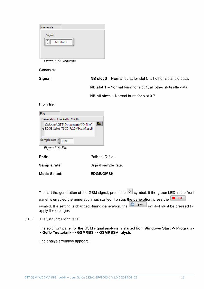
GTTGSM-WCDMARBStoolkit–UserGuide522A1-SP03003-1V1.0.02018-08-02 11
Figure 5-5: Generate
Generate:
Signal: NB slot 0 – Normal burst for slot 0, all other slots idle data. NB slot 1 – Normal burst for slot 1, all other slots idle data. NB all slots – Normal burst for slot 0-7.
From file:
Figure 5-6: File
Path: Path to IQ file.
Sample rate: Signal sample rate.
Mode Select: EDGE/GMSK
To start the generation of the GSM signal, press the symbol. If the green LED in the front
panel is enabled the generation has started. To stop the generation, press the
symbol. If a setting is changed during generation, the symbol must be pressed to apply the changes.
5.1.1.1 AnalysisSoftFrontPanel
The soft front panel for the GSM signal analysis is started from Windows Start -> Program -> Gefle Testteknik -> GSMRBS -> GSMRBSAnalysis.
The analysis window appears:
GTTGSM-WCDMARBStoolkit–UserGuide522A1-SP03003-1V1.0.02018-08-02 12
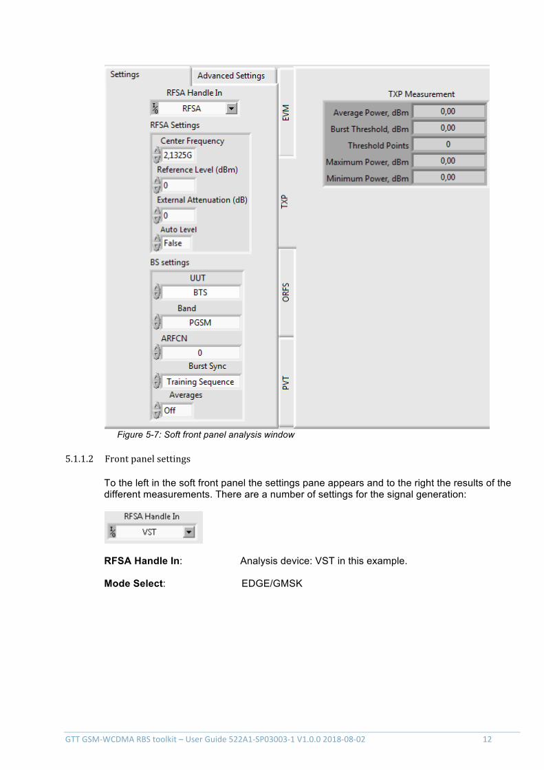
Figure 5-7: Soft front panel analysis window
5.1.1.2 Frontpanelsettings
To the left in the soft front panel the settings pane appears and to the right the results of the different measurements. There are a number of settings for the signal generation:
RFSA Handle In: Analysis device: VST in this example.
Mode Select: EDGE/GMSK

GTTGSM-WCDMARBStoolkit–UserGuide522A1-SP03003-1V1.0.02018-08-02 13
Figure 5-8: RFSA settings
RFSA settings:
Center Frequency: Center frequency of the GSM signal.
Reference Level: GSM signal reference level
External Attenuation, dB: Attenuation in the signal path that must be taken into account.
Auto Level: If true, the system uses the best reference level based on the peak power of the signal measured. If false, the value in the Reference Level settings is used.
Figure 5-9: BS settings
BS settings:
UUT: Select UUT, BTS = Base Transceiver Station, MS = Mobile Station.
Band: Selection of the GSM frequency band.
ARFCN: Absolute Radio Frequency Channel Number. The interval of this number depends on the frequency band.
GTTGSM-WCDMARBStoolkit–UserGuide522A1-SP03003-1V1.0.02018-08-02 14
Burst Sync: Method to synchronize to the data burst. Can be set to None (no sync), Amplitude (-20 dB threshold) or Training sequence.
Averages: On/Off, if set to On the number of averages is set to 200 (this setting is valid for OFRS and EVM measurements)
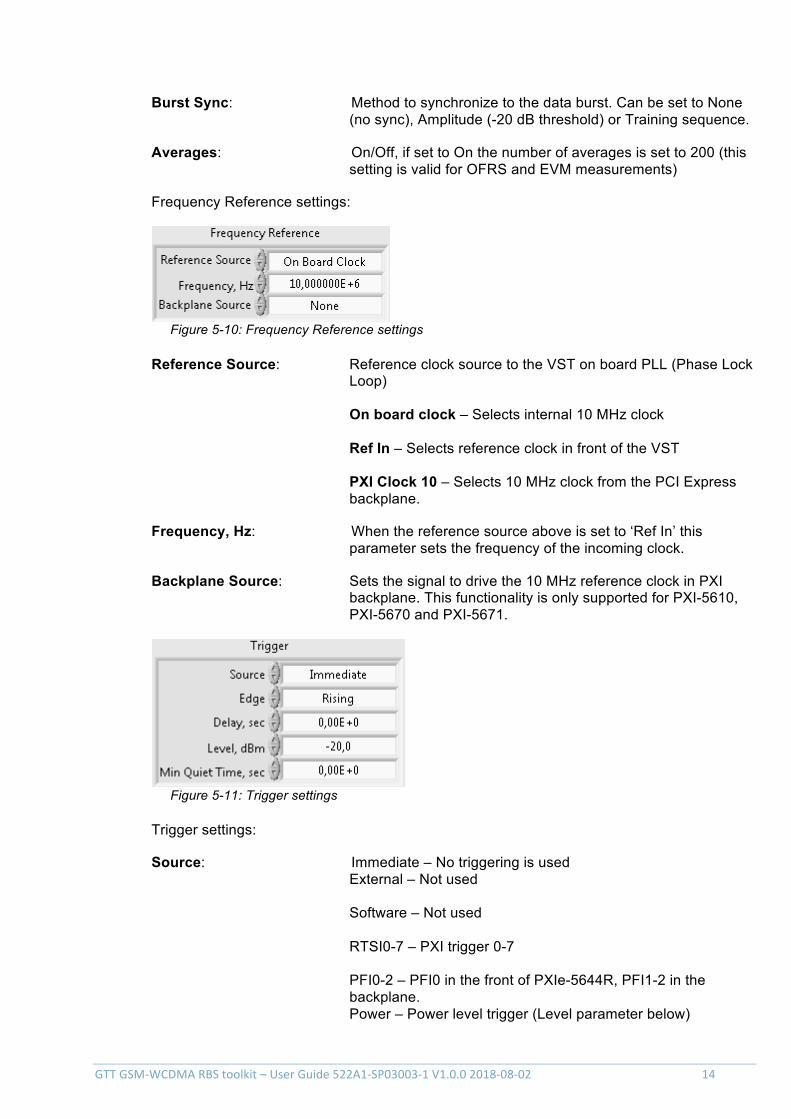
Frequency Reference settings:
Figure 5-10: Frequency Reference settings
Reference Source: Reference clock source to the VST on board PLL (Phase Lock Loop) On board clock – Selects internal 10 MHz clock Ref In – Selects reference clock in front of the VST PXI Clock 10 – Selects 10 MHz clock from the PCI Express backplane.
Frequency, Hz: When the reference source above is set to ‘Ref In’ this parameter sets the frequency of the incoming clock.
Backplane Source: Sets the signal to drive the 10 MHz reference clock in PXI backplane. This functionality is only supported for PXI-5610, PXI-5670 and PXI-5671.
Figure 5-11: Trigger settings
Trigger settings:
Source: Immediate – No triggering is used External – Not used Software – Not used RTSI0-7 – PXI trigger 0-7 PFI0-2 – PFI0 in the front of PXIe-5644R, PFI1-2 in the backplane. Power – Power level trigger (Level parameter below)
GTTGSM-WCDMARBStoolkit–UserGuide522A1-SP03003-1V1.0.02018-08-02 15
Edge: Selects which edge, rising or falling, on which the trigger shall be detected.
Delay, sec: Specifies the time between the trigger event and the start of data acquisition.
Level, dBm: The level to use for power triggering (includes any external attenuation).
Min Quiet Time, sec: Specifies the minimum time the signal must remain below the trigger level in order for the trigger to work.
To start a capture of a WCDMA signal, press the symbol.
5.1.1.3 Frontpanelmeasurements
The measurements results will be found in the different front panel tabs:
- EVM, modulation accuracy measurements
- TXP, Transmit Power measurement
- ORFS, Output RF Spectrum measurement
- PvT, Power versus Time measurements
In section 5.1.2 below there is a more detailed description of each measurement.
5.1.2 Measurementdefinitionsaccordingto3GPP
5.1.2.1 MeanTransmittedRFCarrierPower(TXPtabinSFP)
To verify the accuracy of the mean transmitted RF carrier power across the frequency range and at each power step.
5.1.2.2 ModulationaccuracyEDGE(EVMtabinSFP)
The test purpose is:
1. To verify the correct implementation of the pulse shaping filtering.
2. To verify that at GMSK modulation the phase error during the active part of the time slot does not exceed the specified limits under normal and extreme test conditions and when subjected to vibration.
3. To verify that the frequency error during the active part of the time slot does not exceed the specified limits under normal and extreme test conditions and when subjected to vibration.
GTTGSM-WCDMARBStoolkit–UserGuide522A1-SP03003-1V1.0.02018-08-02 16
4. To verify that at supported modulations 8-PSK, QPSK, AQPSK, 16-QAM and 32-QAM the Error Vector Magnitude (EVM) and the origin offset during the active part of the time slot do not exceed the specified limits under normal and extreme test conditions and when subjected to vibration.
Note: All TRXs in the configuration shall be switched on transmitting full power in all time slots for at least 1 hour before starting the test.
5.1.2.3 TransmittedRFcarrierpowerversustime(PvTtabinSFP)
The test purpose is to verify:
1. The time during which the transmitted power envelope should be stable (the useful part of the time slot);
2. The stability limits;
3. The maximum output power when nominally off between time slots.
5.1.2.4 Spectrumduetomodulationandwidebandnoise(ORFStabinSFP)
The purpose of this measurement is to verify that the output RF spectrum due to modulation and wideband noise does not exceed the specified levels for an individual transceiver.
The system under test shall be tested with one TRX active or with the BTS equipped with only one TRX, at three frequencies (first at RF channel B, second at RF channel M and third at RF channel T). Slow frequency hopping shall be disabled.
5.1.2.5 Switchingtransientsspectrum(ORFStabinSFP)
The purpose of this measurement is to verify the level of the switching transients in the output RF spectrum.
5.2 GTTWCDMARBStoolkit
5.2.1 GenerationSoftFrontPanel
The soft front panel for WCDMA signal generation is started from Windows Start -> Program -> Gefle Testteknik -> WCDMARBS -> WCDMARBSGen.
The generation window appears:
GTTGSM-WCDMARBStoolkit–UserGuide522A1-SP03003-1V1.0.02018-08-02 17
Figure 5-12: the WCDMA signal generation front panel
There are a number of settings for the signal generation:
RFSG Handle In: Generation device, VST (PXIe-5644/5645R) is required for generation.
External Attenuation, dB: Attenuation in the signal path that must be taken into account.
Average Power, dBm: Sets the signal output level. The actual signal level is the power level plus the external attenuator.
Center Frequency, Hz: Carrier frequency set.
Clipping settings:
GTTGSM-WCDMARBStoolkit–UserGuide522A1-SP03003-1V1.0.02018-08-02 18
Mode: Vector/Scalar
Level, %: ?
Figure 5-13: Trigger settings
Trigger settings:
Type: Immediate – No start trigger is configured. Start Trigger – Enables trigger functionality. Restart Trigger – This will restart the capturing of the trigger and signal generation. Note: Start Trigger Delay must be set to at least 10 us.
Source: Trigger input select. PFI0-2 is valid for PXI-5644/5645R. PF0 is located at the front of the VST, PF1 and PF2 on digital IO connector.
Edge: Rising edge/Falling edge, selects on which edge the trigger shall be detected.
PFI Min Pulse Width: Specifies the minimal pulse width in seconds for the PFI lines.
Start Trigger Delay: A configurable trigger delay up to 35 seconds before the generation starts.
Figure 5-14: Frequency reference settings
Frequency reference settings:
GTTGSM-WCDMARBStoolkit–UserGuide522A1-SP03003-1V1.0.02018-08-02 19
Reference Source: Reference clock source to the VST onboard PLL (Phase Lock Loop) Onboard clock – Selects internal 20 MHz clock. Ref In – Selects reference clock in front. PXI Clock 10 – Selects 10 MHz clock from the PCI Express backplane.
Frequency, Hz: When the reference source above is set to “Ref In” this parameter sets the frequency of the incoming clock.
Backplane Source: Sets the signal to drive the 10 MHz reference clock in PXI backplane. This functionality is only supported for PXI-5610, PXI-5670 and PXI-5671.
Figure 5-15: Generate
Generate:
Signal: Signal type. TM1, TM2, TM5 or TM6 for downlink and TC1 for uplink (12.2 kbps, DPCCH: SF = 256, Code = 0, -6.5 dBc, DPDCH, SF = 64, Code = 16, -1.1 dBc, I).
Scramble Code: Scramble code number.
From file:
Figure 5-16: Generation file path
Path: Path to IQ file.
Sample rate: Signal sample rate
File Type: ASCII/BIN/TDMS
GTTGSM-WCDMARBStoolkit–UserGuide522A1-SP03003-1V1.0.02018-08-02 20
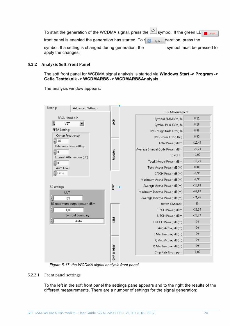
To start the generation of the WCDMA signal, press the symbol. If the green LED in the
front panel is enabled the generation has started. To stop the generation, press the
symbol. If a setting is changed during generation, the symbol must be pressed to apply the changes.
5.2.2 AnalysisSoftFrontPanel
The soft front panel for WCDMA signal analysis is started via Windows Start -> Program -> Gefle Testteknik -> WCDMARBS -> WCDMARBSAnalysis.
The analysis window appears:
Figure 5-17: the WCDMA signal analysis front panel
5.2.2.1 Frontpanelsettings
To the left in the soft front panel the settings pane appears and to the right the results of the different measurements. There are a number of settings for the signal generation:
GTTGSM-WCDMARBStoolkit–UserGuide522A1-SP03003-1V1.0.02018-08-02 21
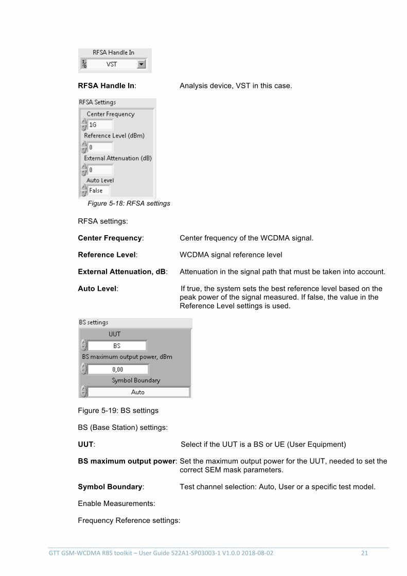
RFSA Handle In: Analysis device, VST in this case.
Figure 5-18: RFSA settings
RFSA settings:
Center Frequency: Center frequency of the WCDMA signal.
Reference Level: WCDMA signal reference level
External Attenuation, dB: Attenuation in the signal path that must be taken into account.
Auto Level: If true, the system sets the best reference level based on the peak power of the signal measured. If false, the value in the Reference Level settings is used.
Figure 5-19: BS settings
BS (Base Station) settings:
UUT: Select if the UUT is a BS or UE (User Equipment)
BS maximum output power: Set the maximum output power for the UUT, needed to set the correct SEM mask parameters.
Symbol Boundary: Test channel selection: Auto, User or a specific test model.
Enable Measurements:
Frequency Reference settings:
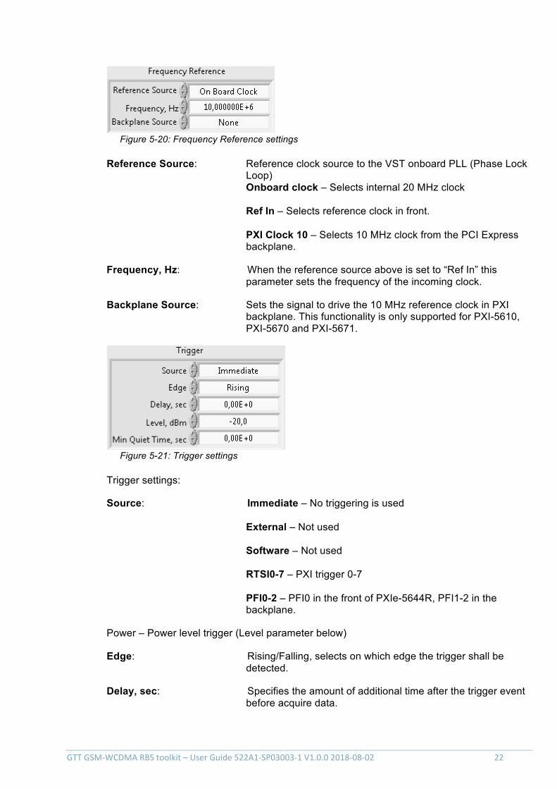
GTTGSM-WCDMARBStoolkit–UserGuide522A1-SP03003-1V1.0.02018-08-02 22
Figure 5-20: Frequency Reference settings
Reference Source: Reference clock source to the VST onboard PLL (Phase Lock Loop) Onboard clock – Selects internal 20 MHz clock Ref In – Selects reference clock in front. PXI Clock 10 – Selects 10 MHz clock from the PCI Express backplane.
Frequency, Hz: When the reference source above is set to “Ref In” this parameter sets the frequency of the incoming clock.
Backplane Source: Sets the signal to drive the 10 MHz reference clock in PXI backplane. This functionality is only supported for PXI-5610, PXI-5670 and PXI-5671.
Figure 5-21: Trigger settings
Trigger settings:
Source: Immediate – No triggering is used External – Not used Software – Not used RTSI0-7 – PXI trigger 0-7 PFI0-2 – PFI0 in the front of PXIe-5644R, PFI1-2 in the backplane.
Power – Power level trigger (Level parameter below)
Edge: Rising/Falling, selects on which edge the trigger shall be detected.
Delay, sec: Specifies the amount of additional time after the trigger event before acquire data.
GTTGSM-WCDMARBStoolkit–UserGuide522A1-SP03003-1V1.0.02018-08-02 23
Level, dBm: The level to use for power triggering (includes any external attenuation).
Min Quiet Time, sec: Specifies the minimum time below the trigger value the signal must remain in order to trigger.
To start a capture of a WCDMA signal, press the symbol.
5.2.2.2 Frontpanelmeasurements
The measurements results will be found in the different front panel tabs:
- ACP (ACLR), Adjacent Channel Leakage Power measurements
- ModAcc (EVM), Modulation Accuracy measurements
- CDP, Code Domain Power measurements
- SEM, Spectrum Emission Mask
- CHP & OBW, Channel Power and Occupied Bandwidth measurements
In section 6.3.3 below there is a more detailed description of each measurement.
5.2.3 Measurementdefinitionsaccordingto3GPP
5.2.3.1 BasestationMaximumOutputPower(CHPtabinSFP)
Maximum output power, Pmax, of the base station is the mean power level per carrier measured at the antenna connector in specified reference condition.
The test purpose is to verify the accuracy of the maximum output power across the frequency range and under normal and extreme conditions for all transmitters in the BS.
5.2.3.2 PrimaryCPICHPoweraccuracy(CDPtabinSFP)
Primary CPICH (P-CPICH) power is the code domain power of the Primary Common Pilot Channel. P-CPICH power is indicated on the BCH. The requirement is applicable for all BS types.
The purpose of the test is to verify, that the BS under test delivers Primary CPICH code domain power within margins, thereby allowing reliable cell planning and operation.
5.2.3.3 Frequencyerror(ModAcctabinSFP)
Frequency error is the measuring of the difference between the actual BS transmit frequency and the assigned frequency. The same source shall be used for RF frequency and data clock generation.
The purpose of this measurement is to verify that the Frequency Error is not too high.
GTTGSM-WCDMARBStoolkit–UserGuide522A1-SP03003-1V1.0.02018-08-02 24
5.2.3.4 Occupiedbandwidth(OBWtabinSFP)
The occupied bandwidth is the width of a frequency band such that, below the lower and above the upper frequency limits, the mean powers emitted are each equal to a specified percentage β/2 of the total mean transmitted power.
The value of β/2 shall be taken as 0.5%.
The test purpose is to verify that the emission of the BS does not occupy an excessive bandwidth for the service to be provided and is, therefore, not likely to create interference to other users of the spectrum beyond undue limits.
5.2.3.5 ACLR(ACPtabinSFP)
Adjacent Channel Leakage power Ratio (ACLR) is the ratio of the RRC filtered mean power centred on the assigned channel frequency to the RRC filtered mean power centred on an adjacent channel frequency.
5.2.3.6 PeakcodeDomainerror(ModAcctabinSFP)
The Peak Code Domain Error is computed by projecting the error vector (EVM) onto the code domain at a specific spreading factor. The Code Domain Error for every code in the domain is defined as the ratio of the mean power of the projection onto that code, to the mean power of the composite reference waveform. This ratio is expressed in dB. The Peak Code Domain Error is defined as the maximum value for the Code Domain Error for all codes. The measurement interval is one timeslot as defined by the C-PICH (when present), otherwise the measurement interval is one timeslot starting with the beginning of the SCH.
It is the purpose of this test to discover and limit inter-code cross-talk.
5.2.3.7 RelativeCodeDomainError(ModAcctabinSFP)
The Relative Code Domain Error is computed by projecting the error vector (EVM) onto the code domain at a specified spreading factor. Only the active code channels in the composite reference waveform are considered for this requirement. The Relative Code Domain Error for every active code is defined as the ratio of the mean power of the error projection onto that code, to the mean power of the active code in the composite reference waveform. This ratio is expressed in dB. The measurement interval is one frame.
The requirement for Relative Code Domain Error is only applicable for 64QAM modulated codes.
5.2.3.8 EVM
The Error Vector Magnitude is a measure of the difference between the reference waveform and the measured waveform. This difference is called the error vector.
5.2.3.9 Spectrumemissionmask(SEMinSFPtab)
The mask defined in ref [2] may be mandatory in certain regions. In other regions this mask may not be applied.
GTTGSM-WCDMARBStoolkit–UserGuide522A1-SP03003-1V1.0.02018-08-02 25
For regions where this clause applies, the requirement shall be met by a base station transmitting on a single RF carrier configured in accordance with the manufacturer's specification. In addition, for a BS operating in non-contiguous spectrum, the requirements apply inside any sub-block gap.
This test measures the emissions of the BS, close to the assigned channel bandwidth of the wanted signal, while the transmitter is in operation.
6 ContactInformation
http://testteknik.se/
Support contact:
Sales contact:
7 Abbreviations ACLR Adjacent Channel Leakage power Ratio
ACP Adjacent Channel Power
API Application Programming Interface
ARFCN Absolute Radio Frequency Channel Number
BCH B CHannel TBD
BER Bit Error Rate
BLER BLock Error Rate
BS Base Station
BTS Base Transceiver Station
CCDF Complementary Cumulative Distribution Function
CDP Code Domain Power
CDR Relative Code Domain Power
CHP CHannel Power
CPICH Common PIlot CHannel
DL Down Link
DLRS DownLink Reference Signal
DUT Device Under Test
E-TM E-UTRA Test Model
E-UTRA Evolved UTRA
EVM Error Vector Magnitude
FRC Fixed Reference Channels
GTTGSM-WCDMARBStoolkit–UserGuide522A1-SP03003-1V1.0.02018-08-02 26
GMSK Gaussian Minimum Shift Keying
GSM Global System for Mobile communications
IQ in-phase and quadrature modulator
MS Mobile Station
NI National Instruments Corporation
OBW Occupied Bandwidth
OFRS Output RF Spectrum
P-CPICH Primary Common PIlot CHannel
P-SS Primary Sync Signal
PAR Peak to Average Ratio
PC Personal Computer
PLL Phase Lock Loop
PVT Power Verses Time
RB Resource Block
RBS Radio Base Station
RF Radio Frequency
RFSA RF Signal Analyser
RFSG RF Signal Generator
RNTI Radio Network Temporary Identifier
RRC Root Raised Cosine
S-SS Secondary Sync Signal
SCH Synchronisation CHannel
SEM Spectrum Emission Mask
SFP Soft Front Panel
SQL Structured Query Language
TAE Time Alignment Error
TDD Time Division Duplex
TDMS Technical Data Management Streaming
TM Test Models
TRX Transceiver
TXP Transmit Power
UE User Equipment
UMTS Universal Mobile Telecommunications System
UTRA UMTS Terrestrial Radio Access
UUT Unit Under Test
VI National Instruments Virtual Instrument
VST Vector Signal Transceiver
GTTGSM-WCDMARBStoolkit–UserGuide522A1-SP03003-1V1.0.02018-08-02 27
WCDMA Wideband Code Division Multiple Access
8 References
[1] 3GPP TS 51.021 (GSM)
[2] 3GPP TS 25.141 (WCDMA)
[3] MIL-STD-1235C (Single and Multi-Level Continuous Sampling Procedures and Tables for Inspection by Attributes)
[4] Implementing Six Sigma: Smarter Solutions Using Statistical Methods, 2nd Edition (Forrest W. Breyfogle III)
[5] GTT GSM-WCDMA DL BER Add-on – User Guide 522A1-SW03005-1
AppendixA-3GPP versions for GSM measurements
List of the versions of the 3GPP standard [1] used for each GSM measurement.
GTT GSM RBS toolkit revision
Modulation Accuracy
Transmit Power
Output RF Spectrum
Power Versus Time
1.0.1 11.2.0 11.2.0 11.2.0 11.2.0
AppendixB-3GPP versions for WCDMA measurements
List of the versions of the 3GPP standard [2] used for each WCDMA measurement.
GTT WCDMA
RBS toolkit
revision
Base Station Output Power
EVM Freq. Error
CDP ACLR OBW SEM Peak Code
Domain Error
Relative Code
Domain Error
1.0.1 11.4.0 11.4.0 11.4.0 11.4.0 11.4.0 11.4.0 11.4.0 11.4.0 11.4.0
GTTGSM-WCDMARBStoolkit–UserGuide522A1-SP03003-1V1.0.02018-08-02 28
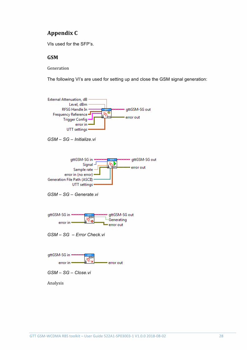
AppendixC
VIs used for the SFP’s.
GSM
Generation
The following VI’s are used for setting up and close the GSM signal generation:
GSM – SG – Initialize.vi
GSM – SG – Generate.vi
GSM – SG – Error Check.vi
GSM – SG – Close.vi
Analysis
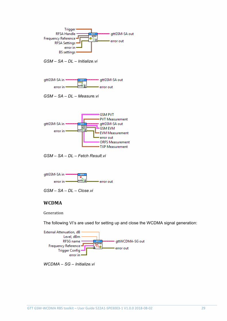
GTTGSM-WCDMARBStoolkit–UserGuide522A1-SP03003-1V1.0.02018-08-02 29
GSM – SA – DL – Initialize.vi
GSM – SA – DL – Measure.vi
GSM – SA – DL – Fetch Result.vi
GSM – SA – DL – Close.vi
WCDMA
Generation
The following VI’s are used for setting up and close the WCDMA signal generation:
WCDMA – SG – Initialize.vi
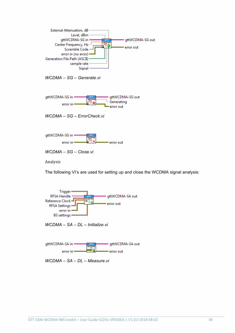
GTTGSM-WCDMARBStoolkit–UserGuide522A1-SP03003-1V1.0.02018-08-02 30
WCDMA – SG – Generate.vi
WCDMA – SG – ErrorCheck.vi
WCDMA – SG – Close.vi
Analysis
The following VI’s are used for setting up and close the WCDMA signal analysis:
WCDMA – SA – DL – Initialize.vi
WCDMA – SA – DL – Measure.vi
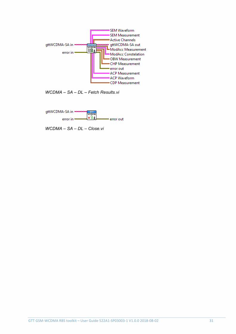
GTTGSM-WCDMARBStoolkit–UserGuide522A1-SP03003-1V1.0.02018-08-02 31
WCDMA – SA – DL – Fetch Results.vi
WCDMA – SA – DL – Close.vi