GTS-SWR M-Sens 2 Manual
27
1
Transcript of GTS-SWR M-Sens 2 Manual

1
2
SUMMARY
1 SYSTEM OVERVIEW 3
2 FUNCTION 4
3 SAFETY 5
3.1 Regular use 5
3.2 Marking of dangers 5
3.3 Operational safety 5
3.4 Technical progress 6
4 MOUNTING AND INSTALLATION 6
4.1 Scope of delivery 6
4.2 Necessary auxiliaries 6
4.3 Mounting of the sensors 6
4.4 Mounting of the evaluation unit 10
5 ELECTRICAL CONNECTION 11
6 COMMISSIONING 12
7 MENU STRUCTURE 14
8 SYSTEM ADJUSTMENTS IN DETAIL 17
9 WIRING EXAMPLE 25
10 MAINTENANCE 25
11 GUARANTEE 25
12 TROUBLE SHOUTING 26
13 TECHNICAL DATA 27

3
1. System overview
A complete M-Sens 2 unit consists of the following components:
• Flange (mounting in screw, hopper)
• 1 to 3 sensors with 1,8 m connecting cable
• Evaluation unit MME 100 resp. MME 300
in a field housing
• C-box for connecting of sensor and evaluation unit
The sensor is connected by a shielded, 4-wired cable to the evaluation unit; the maximal dis-
tance between these devices can be at most 300 m.

4
2. Function
The M-Sens 2 sensor functionality is based on precise high-frequency measurement and direct
digitalization of measured values, wherefrom results a high resolution. As the materials sur-
face and capillary moisture influences strongly its specific conductive capacity, the moisture
can be measured exactly by a constant averaged bulk density.
The calibration can be done very simply by the operator by pressing the button and entering
the referenced moisture contents.
In this context it is convenient that measured value fluctuations by bulk density variations are
balanced by an internal filter function. Additionally, measured value fluctuations by tempera-
ture variations are compensated automatically by the sensor.
Fig. 3: Injection and reflexion of high frequency

5
3. Safety
The measuring system M-Sens designed and built according the latest technology has been
tested to be safe and was shipped in safe condition. Nevertheless persons or objects may be
endangered by components of the system if these are operated in an inexpert manner. There-
fore the operational instructions must be read completely and the safety notes must be fol-
lowed. In case of inexpert or irregular use, the manufacturer will refuse any liability or guar-
antee.
3.1 Regular Use
Only original spare parts and accessories of SWR engineering must be used.
3.2 Marking of dangers
Possible dangers when using the measuring system are marked by the following symbols in
the operating instructions:
Warning!
This symbol in the operating instructions marks actions,
which may represent a
danger for life and limb of persons when carried out in an inexpert
manner.
Danger!
All actions which may endanger objects are marked with this symbol in the
operating instructions.
3.3 Operational safety
The measuring system must be installed by trained and authorised personnel only.
Switch off the supply voltage for all maintenance, cleaning or inspection works on the
tubes or on components of the M-Sens 2. Follow the notes of the chapter "mainte-
nance".
Before hot-work the sensor must be removed from the installation place.
The components and electrical connections must be checked for damages regularly.
If a damage is found, it is to be repaired before further operation of the instruments.

6
3.4 Technical progress
SWR reserves the right to adapt technical data to the technical progress without particular
advance notice. If you have any questions, SWR engineering will be pleased to inform you on
possible changes and extensions of the operating instructions.
4. Mounting and installation
4.1 Delivery scope
Evaluation unit in the field housing
Sensor
Mounting
C-box
4.2 Necessary auxiliaries
Screw driver 2,5 mm
Allen key 5 mm
4.3 Mounting of the sensors
M-Sens 2 is designed for continuous moisture measurement. Most important condition for
correct measurement is the right choice of the mounting place of the sensor. That is, when
using chutes or conveyor belts, it is very important to have a almost even material height in
front of the sensor window.
The flange is welded without sensor and dummy plate in the opening at determined mounting
place. Sensor and dummy plate are mounting by means of plumbing lubricant. For applica-
tions without over-pressure it is possible to renounce the 2 sealing rings.
Attention!
The Flange mustn’t be welded together with the sensor or dummy plate (incl. the seal-
ing
rings).

7
APPLICATIONS – PRACTICAL EXAMPLES
• Installation in a screw
The installation of a moisture sensor in screw feeders proved to be very advantageous, since
the material passes by the sensor window in even intervals and with relatively constant bulk
density.
• Installation on a conveyor belt
By means of the online moisture measurement of solids on a conveyor belt, the operator can
react in due time if the material is too humid or too dry. In consequence, plugging of subse-
quent aggregates can be prevented.

8
• Installation in a bin
Another installation alternative is to mount a sensor at a bins outlet. Due to constant bulk den-
sity in case of a filled bin, the sensor finds an almost unchanging measuring field for monitor-
ing the residual moisture. Thus, M-Sens 2 avoids that too damp material reaches the next pro-
duction level or arrives into the loading.
• Control of dryer by means of moisture measurement
After the material, lying on the belt, has passed through the dryer tunnel, it gets withdrawn
from the hot air zone. At the end of the belt the dried material falls in a screw conveyor which
transports it to the processing.
The operator queries the following points: Has the material reached really the desired residual
moisture value? That is, has he chosen the right cycle time and temperature?
M-Sens 2 provides accurate and reliable online moisture values for the process control, by
which constant moisture in close tolerances of the output material can be met.
This process optimization enables the operator to manage high savings and quality improve-
ments.

9
• Moisture measurement in a mixer
M-Sens 2 can be installed, even later on, in all types of mixers. The measuring values logging
is done by within the moving material during the mixer procedure.
With the measured moisture value of the material in the dryer process parameters like deten-
tion time and dosage quantity can be controlled.
For this purpose M-Sens 2 is connected to a PLC or another process control system.

10
4.4 Mounting of the evaluation unit
The whole electronic equipment can be installed at a maximum distance of 300m from the
sensor. The housing is prepared for wall mounting
Fig. 10: Field housing for the evaluation unit
Fig. 11: Field housing for the C-box
The C-box contains fuses and resistances in order to guarantee the communication by
the Mod-bus between sensor and evaluation unit.

11
5. Electrical connection
Supply voltage according to the version.
Fig. 12: Electrical connection of the evaluation unit
Fig. 13: Electrical connection of the C-box

12
6. Commissioning
AT the first commissioning of the M-Sens 2 it is necessary to calibrate the sensor.
Please consider:
Correct connection between sensor, C-box and evaluation unit
Correct installation of the sensor in respect to the wall thickness
In case of negative results in spite of consideration of the points as stated above, please con-
tact SWR.
Commissioning of the M-Sens 2
After the delivery the sensor is not calibrated to the product(s), so each calibration and
parameterization has to be executed during the commissioning. Therefore it is necessary to
assign the measured moisture to the desired display and to the initial value. The menu func-
tions are very self-explanatory. In the following a short introduction to the menu overview:
Changed values are confirmed and saved by pushing the arrow button. To abandon the menu
without saving the changes push the C-button.
Starting the menu:
Entering the menu takes place by pushing 5 sec the in-
visible key lower right corner of the touch screen panel.
Basic function For the measurement and display of the moisture in %,
there 2-3 moisture measurement executed with known
and different moisture values. After having entered the
according moisture values by the panel, the system calcu-
lates the moisture in % on the basis of those measurement
values.
Hereby the basic function is initiated.
Adjustment The menu point 1 “products” can be used for every of the
4 possible products.
Alarm Alarm can be determined for every product in the menu
point “measurement range”.
Current / Voltage output The definition of the initial values has to be done in the
Voltage menu point “analogue outputs”. The output value
(current/value) is assigned to the measurement range.
Standard MIN = 4 mA
MAX = 20 mA
The measurement range filter serves to the adjustment to
slower measuring devices or to continuous output at the
analogue output.
Digital inputs Under menu point 3 you define the digital inputs. Every
digital input can be used to start and stop the moisture
measurement.
13
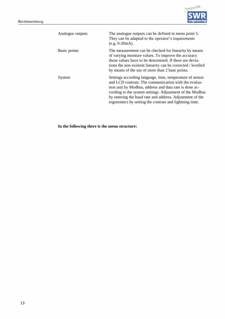
Analogue outputs The analogue outputs can be defined in menu point 5.
They can be adapted to the operator’s requirements
(e.g. 0-20mA).
Basic points The measurement can be checked for linearity by means
of varying moisture values. To improve the accuracy
those values have to be determined. If there are devia-
tions the non existent linearity can be corrected / levelled
by means of the use of more than 2 base points.
System Settings according language, time, temperature of sensor
and LCD contrast. The communication with the evalua-
tion unit by Modbus, address and data rate is done ac-
cording to the system settings. Adjustment of the Modbus
by entering the baud rate and address. Adjustment of the
ergonomics by setting the contrast and lightning time.
In the following there is the menu structure:

14
7. Menu structure
1 Products Products 1…4
1.1 Measurement range
1.1.1 Product name Choice of material (8 char)
1.1.2 Unity Choice unit text, e.g. % H2O
1.1.3 Decimal place Decimal place position
1.1.4 Measurement range init Range of 0…100 %
1.1.5 Measurement range end Range of 0…100 %
1.1.6 Filter value Range of 0,1…999,9 s
1.2 Alarm 1
1.2.1 Alarm type MIN / MAX / none
1.2.2 Alarm value Range of 0…100 % in phys. units
1.2.3 Alarm dead time Range of 0,1…99,9 s
1.2.4 Alarm hysteresis Range of 0,1…99,9 %
1.2.5 Operation modus Operational- or
closed current principle
1.3 Alarm 2
1.3.1 Alarm type MIN / MAX / none
1.3.2 Alarm value Range of 0…100 % in phys. units
1.3.3 Alarm dead time Range of 0,1…99,9 s
1.3.4 Alarm hysteresis Range of 0,1…99,9 %
1.3.5 Operation modus Operational- or
closed current principle

15
1.4 Calibration
1.4.1 Calibration filter Range of 0,1…999,9 s
1.4.2 Number of calibration points Range of 2…5 base points
1.4.3 Calibration factor for sensor 1 Rating of sensor signal with several
sensors used and disconnecting of 1
sensor with 0
1.4.4 Calibration factor for sensor 2 Rating of sensor signal with several
sensors used and disconnecting of 1
sensor with 0
1.4.5 Calibration factor for sensor 3 Rating of sensor signal with several
sensors used and disconnecting of 1
sensor with 0
1.4.6 Calibration point 1 Measurement range init and end
1.4.7 Measured value Record of input value
1.4.8 Calibration point 2
1.4.9 Calibration
… (depends on the number of the
calibration points)
1.4.10 Calibration point N Measurement range init and end
1.4.11 Measured value Record of input value
For 2.1 to 2.4 / 3.1 to 3.4 / 4.1 to 4.4 – same way
5 Analogue output
5.1 Beginning of range Range of 0…22 mA (Std. 4 mA)
5.2 End of range Range of 0…22 mA (Std. 20 mA)
5.3 MIN limit Range of 0…22 mA (Standard 3 mA)
5.4 MAX limit Range of 0…22 mA (Std. 20 mA)
5.5 Alarm value Range of 0…22 mA (Standard 3 mA)
5.6 Filter time Range of 0,1…999,9 s (Standard 1 s)
5.7 Calibration: 4 mA Adjust output current
(calibration to 4 mA)
5.8 Calibration: 20 mA Adjust output current
(calibration to 20 mA)

16
6 Digital inputs
6.1 Digital input 1
6.1.1 Function none; measurement stop or
product choice
6.1.2 Effect direction direct or inverted
6.1.3 Filter Range of 0,1…99,9 s
6.2 Digital input 2
6.2.1 Function none; measurement stop or
product choice
6.2.2 Effect direction direct or inverted
6.2.3 Filter Range of 0,1…99,9 s
7 System
7.1.1 Baud rate 4800 / 9600 / 19200 /
38400
7.1.2 Modbus address Range of 1…250
7.1.3 Contrast
7.1.4 Language D / F / E
7.1.5 Backlight
7.1.6 T-Display ON / OFF

17
8. System adjustments in detail
1.1 Measurement range
1.1.1 Product name
Select the name of medium and location (max. 8 char).
Choose the characters with and and the each corresponding position (1...8) with and With C you clear the character and with the input is accepted and you quit the menu level.
1.1.2 Unity
Choice of the measurement value as % H2O or % TS.
Choose the characters with and and the each corresponding position (1...6) with and With C you clear the character and with the input is accepted and you quit the menu level.
1.1.3 Decimal position
Fixation of the decimal position in the display.
With and you make a choice according to the display. With C you quit the menu point without any change and with the input is ac-cepted and you quit the menu level.
1.1.4 Measurement range init
Input of beginning value of the measurement range between 0…100 %. Standard: 0.0
With C you set the value to 0.0. With the num-bers you input the beginning value and with the input is accepted and you quit the menu level.
1.1.5 Measurement range end
Input of end value of the measurement range be-tween 0…100 %. Standard: 0.0
With C you set the value to 1.0. With the num-bers you input the beginning value and with the input is accepted and you quit the menu level.
Measurement range
Product name
Material
C
Measurement range
Unity
% H2O
C
Measurement range
Decimal position
000.0
C
Meas. range 7 8 9 Init
4 5 6 0.0 % H2O
1 2 3
C 0
Meas. range 7 8 9 End
4 5 6 80.0
%
H2O 1 2 3
C 0

18
1.1.6 Filter value
Setting of the damping time between (range be-tween 0,1 ... 999,9 s).
With C you set the value to 0.0. With the num-bers you input the beginning value and with the input is accepted and you quit the menu level.
1.2 Alarm 1
With and you choose the menu point. With C you quit the menu point without any change and with the input is accepted and you arrive 1 menu point lower to make your settings.
1.2.1 Alarm type
Choose the limits: MIN und MAX or none.
With and you make a choice according to the display. With C you quit the menu point without any change and with the input is ac-cepted and you arrive 1 menu point lower to make your settings.
1.2.2 Alarm value
Choose the response threshold of measurement end values in phys. unities (range between 0 ... 100 %).
With C you set the value to 0.0. With the num-bers you input the beginning value and with the input is accepted and you quit the menu level.
1.2.3 Alarm dead time
Choose the time, how long the value above and under the limit has to be, before the alarm relay switches (range between 0,1 ... 99,9 s).
With C you set the value to 0.0. With the numbers you input the beginning value and with the input is accepted and you quit the menu level.
1.2.4 Alarm hysteresis
Choose the value for clearing the alarm. Range between 0,1 ... 99,9 % in the defined meas-urement range.
With C you set the value to 0.0. With the num-bers you input the beginning value and with the input is accepted and you quit the menu level.
Meas. range 7 8 9 Filter
4 5 6 1.0 s
1 2 3
C 0
1.2.Alarm 1
1.2.1.Type Minimum
1.2.2.Value 1.0
1.2.3.Dead time 0.1s C
1.2.4.Hyst. 1.0%
Alarm 1
Alarm type
Minimum
C
Alarm 1 7 8 9 Alarm value
4 5 6 10.0 % H2O 1 2 3
C 0
Alarm 1 7 8 9 Dead time
4 5 6 1.0 s
1 2 3
C 0
Alarm 1 7 8 9 Hysteris
4 5 6 1.0 %
1 2 3
C 0
19
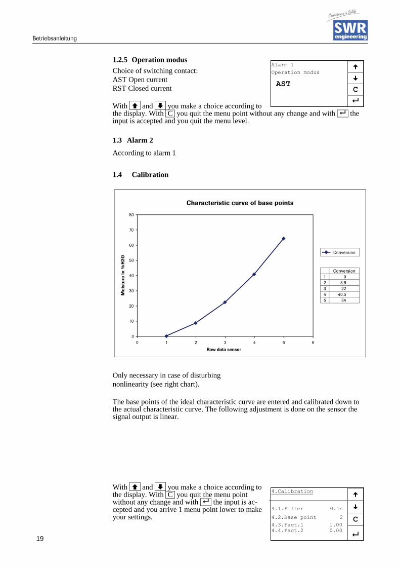
1.2.5 Operation modus
Choice of switching contact:
AST Open current
RST Closed current
With and you make a choice according to the display. With C you quit the menu point without any change and with the input is accepted and you quit the menu level.
1.3 Alarm 2
According to alarm 1
1.4 Calibration
Only necessary in case of disturbing
nonlinearity (see right chart).
The base points of the ideal characteristic curve are entered and calibrated down to the actual characteristic curve. The following adjustment is done on the sensor the signal output is linear.
With and you make a choice according to the display. With C you quit the menu point without any change and with the input is ac-cepted and you arrive 1 menu point lower to make your settings.
Alarm 1
Operation modus
AST
C
4.Calibration
4.1.Filter 0.1s
4.2.Base point 2 C 4.3.Fact.1 1.00
4.4.Fact.2 0.00

20
1.4.1 Calibration filter
Damping filter in order to slow down disturbed signals during the calibration (no effect on output and display); Range between 0,1 and 999,9 s.
With C you set the value to 0.0. With the num-bers you input the beginning value and with the input is accepted and you quit the menu level.
1.4.2 Number of calibration points
Enter the necessary number of base points (be-
tween 2-5).
With C you set the value to 0.0. With the num-bers you input the beginning value and with the input is accepted and you quit the menu level.
1.4.3 Calibration factor for sensor 1
Weighting of sensor signals by using several sen-sors; Disconnection of a sensor with 0. With and you make a choice according to the display. With C you quit the menu point without any change and with the input is ac-cepted and you arrive 1 menu point lower to make your settings.
1.4.4 Calibration factor for sensor 2
According to sensor 1
1.4.5 Calibration factor for sensor 3
According to sensor 1
1.4.6 Calibration point 1
Choose the measured value in physical unities – be-ginning and end of measurement range.
1.4.7 Measured value
Input value is collected and assigned to the shown measured value.
1.4.8 Calibration point 2
Choose the measured value in physical unities – beginning and end of measurement range.
1.4.9 Measured value
…(depends on the number of calibration points)
Calibration 7 8 9 Filter
4 5 6 1.0 s
1 2 3
C 0
Calibration 7 8
9 Base points
4 5 6 2
1 2 3
C 0
Calibration 7 8
9 Factor 1
4 5 6 1.00
1 2 3
C 0
Calibration 7 8 9 Calibr.-Pt. 1
4 5 6 10.0 % H2O 1 2 3
C 0
Calibration
Calibr.-Pt. 1
C 0
Act.: 0

21
1.4.10 Calibration point N Choose the measured value in physical unities – beginning and end of measurement range.
1.4.11 Measured value Input value is collected and assigned to the shown measured value.
For 2.1 to 2.4 / 3.1 to 3.4 / 4.1 to 4.4 : analogue to point 1
5. Analogue output
With and you make a choice according to the accentuation. With C you quit the menu point without any change and with the input is ac-cepted and you arrive 1 menu point lower to make your settings.
5.1 Beginning of range
Choose the output in the range of 0 ... 22 mA (Standard 4 mA).
With C you set the value to 0.0. With the num-bers you input the beginning value and with the input is accepted and you quit the menu level.
5.2 End of range
Choose the output in the range of 0 ... 22 mA (Standard 20 mA).
With C you set the value to 0.0. With the num-bers you input the beginning value and with the input is accepted and you quit the menu level.
5.3 MIN limit
Choose the minimal output value in the range of 0 ... 22 mA (Standard 3 mA).
With C you set the value to 0.0. With the num-bers you input the beginning value and with the input is accepted and you quit the menu level.
5.4 MAX limit
Choose the minimal output value in the range of 0 ... 22 mA (Standard 20 mA).
With C you set the value to 0.0. With the num-bers you input the beginning value and with the input is accepted and you quit the menu level.
5.Analog. outupt
5.1.Beginning 4.0mA
5.2.End 20.0mA
5.3.MIN 0.3mA C
5.4.MAX 21.0mA
Anal. output 7 8 9 Range beg.
4 5 6 4.0 mA
1 2 3
C 0
Anal. output 7 8 9 Range end
4 5 6 20.0 mA
1 2 3
C 0
Anal. output 7 8 9 MIN limit
4 5 6 3.0 mA
1 2 3
C 0
Anal. output 7 8 9 MAX limit
4 5 6 20.0 mA
1 2 3
C 0

22
5.5 Alarm value
Choose the output value for the alarm (sensor error or an internal alarm); at the same time the relay 3 drops down. Range of 0 ... 22 mA (Std 3 mA)
With C you set the value to 0.0. With the num-bers you input the beginning value and with the input is accepted and you quit the menu level.
5.6 Filter time
Choose the filter time for the current output in the
range of 0,1 ... 999,9 s (Standard 1 s)
With C you set the value to 0.0. With the num-bers you input the beginning value and with the input is accepted and you quit the menu level.
5.7 Calibration: 4mA
Set the minimal current output. Fit to the external measurement system (at differing display).
Adapt the current output to 4 mA with the keys < < and >> quickly and with the keys < und > slowly. With the input is accepted and you quit the menu level, with C you quit the menu point without any change.
5.8 Calibration: 20mA
Set the maximal current output. Fit to the external measurement system (at differing display).
Adapt the current output to 4 mA with the keys < < and >> quickly and with the keys < und > slowly. With the input is accepted and you quit the menu level, with C you quit the menu point without any change.
6. Digital inputs
It is only necessary for stopping and starting the
measurement via an external control line (for wir-
ing see 8.1).
With and you make a choice according to the display. With C you quit the menu point without any change and with the input is accepted and you arrive 1 menu point lower to make your settings.
6.1 Digital input 1
With and you make a choice according to the accentuation. With C you quit the menu point without any change and with the input is ac-cepted and you arrive 1 menu point lower to make your settings.
Anal. output 7 8 9 Alarm value
4 5 6 3.0 mA
1 2 3
C 0
Anal. output 7 8 9 Filter time
4 5 6 3.0 s
1 2 3
C 0
Anal. output
Calibration 4.0mA
C
<< <
> >>
Anal. output
Calibration 20.0mA
C
<< <
> >>
6.Digital inputs
6.1.Digital input 1
6.2.Digital input 2
C
6.1. Dig. input1
6.1.1.Funct. none
6.1.2.Direct. direct
6.1.3.Filter 1.0s C
23
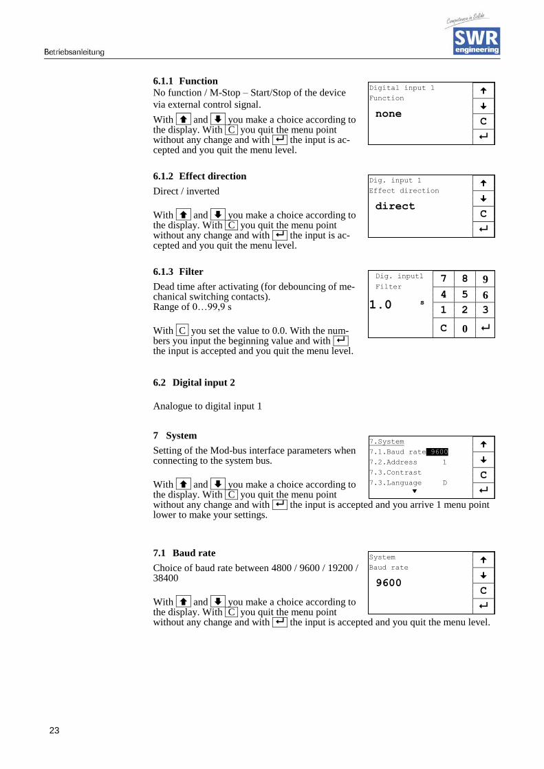
6.1.1 Function
No function / M-Stop – Start/Stop of the device
via external control signal.
With and you make a choice according to the display. With C you quit the menu point without any change and with the input is ac-cepted and you quit the menu level.
6.1.2 Effect direction
Direct / inverted
With and you make a choice according to the display. With C you quit the menu point without any change and with the input is ac-cepted and you quit the menu level.
6.1.3 Filter
Dead time after activating (for debouncing of me-chanical switching contacts). Range of 0…99,9 s
With C you set the value to 0.0. With the num-bers you input the beginning value and with the input is accepted and you quit the menu level.
6.2 Digital input 2
Analogue to digital input 1
7 System
Setting of the Mod-bus interface parameters when connecting to the system bus.
With and you make a choice according to the display. With C you quit the menu point without any change and with the input is accepted and you arrive 1 menu point lower to make your settings.
7.1 Baud rate
Choice of baud rate between 4800 / 9600 / 19200 / 38400
With and you make a choice according to the display. With C you quit the menu point without any change and with the input is accepted and you quit the menu level.
7.System
7.1.Baud rate 9600
7.2.Address 1
7.3.Contrast C
7.3.Language D
System
Baud rate
9600
C
Digital input 1
Function
none
C
Dig. input 1
Effect direction
direct
C
Dig. input1 7 8 9 Filter
4 5 6 1.0 s
1 2 3
C 0

24
7.2 Modbus Address
Setting of Mod-bus address between 1 ... 250.
With C you set the value to 0.0. With the num-bers you input the beginning value and with the input is accepted and you quit the menu level.
7.3 Contrast
Adapt the contrast to desired value with the keys << und >> quickly and with the keys < und > slowly. With the input is accepted and you quit the menu level. With C you quit the menu point without any change.
7.4 Language
Choose of language between D / F / ENG
With and you make a choice according to the display. With C you quit the menu point without any change and with the input is ac-cepted and you quit the menu level.
7.5 Backlight
Setting of durable lightning or the luminescence (in min).
With C you set the value to 0 (equals to durable lightning) by means of the numbers and with the input is accepted and the menu level is quitted.
7.6 T. -Display
Determine if the temperature is shown in the dis-
play – the values are on and off
There is no temperature output by analogue out-put!
With and you make a choice according to the display. With C you quit the menu point without any change and with the input is accepted and you quit the menu level.
System 7 8 9 Address
4 5 6 1
1 2 3
C 0
System
Contrast
C
<< <
> >>
System
Language
D
C
System 7 8 9 Backlight
4 5 6 0 min
1 2 3
C 0
System
Temp. display
off
C

25
9. Wiring example
Digital inputs
RV= (( Ust - 1,6V ) / 20mA ) - 2kOhm
10. Maintenance
Warning!
Danger of shock with open housing!
Switch off the supply voltage for all maintenance or repair works on the measuring
system. The tube must not be in operation during a sensor exchange.
Repair and maintenance work must be carried out by trained or expert personnel only.
The system is maintenance-free.
11. Warranty
Warranty is granted for one year starting from delivery date under the condition that the op-
erational instructions have been followed, no interventions on the appliances have been made
and the components of the system show no mechanical damage or wear resistance.
In case of a defect during the warranty period, defective components are repaired or are re-
placed free of charge. Replaced parts turn into the property of SWR. If desired by the cus-
tomer that the parts should be repaired or replaced in its factory, then the customer has to take
over the costs for the SWR-service staff.
SWR is not responsible for damage, which did not develop at the delivery article; especially
SWR is not responsible for escaped profit or other financial damages of the customer.
Ust

26
12. Trouble shooting
Warning!
The electrical installation must be checked only by expert personnel.
Problem Cause Measure
System out of work Power supply inter-
rupted
Check the power supply.
Cable break Check the connecting cables for a possible
break of a cable
Defective fuse Exchange fuse in the field housing
Defective device Contact SWR
Measuring system
outputs wrong values
Incorrect calibration
Delete input signal correction, new cali-
bration
according to section 6
Calibration shifted by
Abrasion or caking on
front end of sensor
Delete input signal correction, new cali-
bration
according to section 6
Malfunction of sen-
sor
Sensor not properly
connected Check cable
Sensor damaged Replace sensor
No 24 VDC supply on
sensor
Assure right power supply
Voltage drop on the
supply
line too highly
Examine cable lengths on the basis of the
table
in chapter 4.5
Relay flickering Hysteresis too small Increase hysteresis, check effects caused
by external devices.
Do not open, otherwise the warranty claims expire!

27
13. Technical data
Sensor
Housing Stainless Steel 1.4571
Sensor surface Ceramics
Ex protection Zone 22 (dust), zone 2 (gas)
Protection category IP 67 according to EN 60529
Ambient temperature 0 … +80 °C
Working pressure Max. 10 bar
Power consumption 0,6 W
Response time 0,1 sec
Weight Ca. 1000 g
Measuring range 0 … 85 % residual moisture
Accuracy
0,1 % absolutely
in the calibrated measurement range
Connection channel Shielded cable 4-wired, 0,25 mm2
Evaluation unit
Supply voltage 110/230 VAC (50 Hz) / 24 VDC
Power consumption 20 W / 24 V
Current consumption Max. 1 A @ 24 V
Protection category IP65 according to EN 60529/10.91
Ambient temperature -10 … +45 °C
Dimensions 258 x 237 x 174 mm (WxHxD)
Weight Ca. 2,5 kg
Interface RS232, RS485
Cable gland 3 x M16 (4,5-10 mm ø)
Connecting terminals/
Conductor cross-section
0,2-2,5 mm2 [AWG 24-14]
Current output signal /
voltage output signal
2 x 4 … 20 mA (0 … 20 mA),
load < 700 Ω
or 2 … 10 V (0 … 10 V),
load > 2 kΩ
Switched output measurement
alarm
Relay with switching contact
Max. 250 VAC, 1A
Digital inputs
2 inputs for active external control signals
Data protection Flash
EN 080618
Robert
Typewritten text
GTS, Inc. PO Box 799, Shalimar, FL 32579 Ph: 850-651-3388 Fx: 850-651-4777 Email: [email protected] Website: www.onthelevel.com