GSMBU-ZB - RhinoCo Technologydownloads.rhinoco.com.au/products/gsmbu-zb/gsmbu... · Standard...
15
1 Multipath Alarm Communication System Gprs Input Output modul E Version : 2.0 installation and programming reference GSMBU-ZB Easy Operation Dialer SMS Messaging INSTRUCTION MANUAL
Transcript of GSMBU-ZB - RhinoCo Technologydownloads.rhinoco.com.au/products/gsmbu-zb/gsmbu... · Standard...

1
Multipath Alarm Communication System
Gprs Input Output modul E
Version : 2.0 installation and programming reference
GSMBU-ZB
Easy Operation Dialer SMS Messaging
I N S T R U C T I O N M A N U A L

2
Features:
GSM service priovider independent 4 band GSM/GPRS modem Encrypted GPRS communication 24 hours on line connection with Montoring Station Server (ETMS) or BlackBox Two Server setting features Standard PSTN telephone output to start and receive calls from GSM network. Standard Security DTMF communicator connection to any control panels to transmit signals in several path Elevator rescue feature with two way voice communication Back-up operation to change standard PSTN lines to GSM subscribtion Security Control panel features (Arming and Disarming by proximity reader 16 EOL input RS485 connection 4 input zone type 3 programmable output The outputs can be controlled by SMS or through ETMS software Arming by Proxy card, SMS or ETMS sotfware. Receiving and forwarding SMS (Text) messages Local programming through standard RS232 port Remote firmware change through GPRS network Every panel could be locked by password, AC fault delay 2 way voice connection through external microphone and loudspeaker Volume control adjustable by software Programming software on Windows

3
1.0. GIO300s v2, Hardware features: 1.1. Main parts:
1. Antenna connector 2. SIM300s 4 band GSM/GPRS modem 3. Sim card holder to use with any provider SIM card 4. Programming and external modem connector 5. External module and ribbon cable connector 6. Output LED indicators 7. Zones conectors 8. System connectors
1.1.1. LED descriptions:
LED Nr 1 : GPRS level This LED is blinking if the modem connected to the GSM GPRS network. Pulses between 1-5 under 1 second is the signal strength Led Nr 2: Watchdog This led is blinking periodically if the system operation is ok. If the LED does not blink, restart the panel by power in-out procedure. If problem persist please conact your distributor or manufacturer. LED Nr 3-5 : Output 1- Output 3 The LEDs are for showing the active status of the Outputs Led Nr 6 : Reserved for future features
1.1.2. The system connector: AC-AC: AC 16VAC, 20VA GND: Battery Negative B+: Battery Positive S+ Solar cell positive +12,A,B,GND: RS485 bus Phone: Standard communicator or external
telephone set connector Line: Connection for incoming PSTN line, if exist
1.1.3. In and output connectors: Z1-Z8: Input Out1-Out3: Outputs (Open collector max 500mA) +12V: Protected power supply GND: Negative
1.2. Inputs and Outputs: 1.2.1. Inputs: Z1-Z8 Inputs:
1.2.2. Outputs: O1-O3, Open-collector:
2. Specification: Primary power supply requirement : 15-18VAC 20 VA Backup battery: max. 12 V 7,5 Ah Max Current: 150mA Peak current: Max 1 A Max current on 12 V DC 1,5A RS485 power line limit: 1,2A automatic Detector auxiliary power limit: 1A Dimensions: 130x112x15mm Size of screw terminals: Ø2,5mm SIM card: Independent SIM modul: SIM300s v2 GSM/GPRS module: SIM300s v2 9 pin: RS232 connector GPRS communication: 128 bit encrypted Outputs : max. 500mA RS485 bus 1200m
Inputt: Zx Zone Number EOL
1 2,2K1 2 3,3K 3 2,2K2 4 3,3K5 2,2K 3 6 3,3K7 2,2K 4 8 3,3K 9 2,2K5 10 3,3K 11 2,2K6 12 3,3K 13 2,2K 7 14 3,3K15 2,2K
8 16 3,3K
Output Max.
Current „I”
Remote control
Programing
O1 500mA SMS/ETMS RS232/ETMS
O2 500mA SMS/ETMS RS232/ETMS
O3 500mA SMS/ETMS RS232/ETMS

4
3. Expansion boards and accessories: 3.2. External modul (GIO300s-ext):
GIO300s-ext
1. GIO300s-ext 2. Microphone, and earphone connector 3. RS232 connector 4. In and outputs 5. 20 pin connector
3.2.1. Microphone and earphone connector…
Attention: You need to clarify voltage levels of the module. There is 2.5V active voltage ont he microphone input without load. The output ONLY could be connected to speakers with impedance more than 330 Ohms. 3.2.2. RS 232 connector: A GIO 300s-ext is to be used to program the main board.
Connect the module with a standard serial cable to the serial port of the computer. 3.3. Programming module:
GIO300s-prg
Connect the module with a standard serial cable to the serial port of the computer.
3.4. 20 pin connector: For ribbon cable leads if needed.
Attention: You must make sure that the module is correctly connected and adjusted voltage is applied accordingly. There is 2.5V active voltage ont he microphone input without load. The output ONLY could be connected to speakers with impedance more than 330 Ohms. 3.5. Proximity Card reader: 3.5.1. Proximity Card reader:
This is an arming device to be connected to the panel by the RS485 connector. More than one reader could be used on the same bus The maximal distance from the panel is 1200m. The GIO2 control panel can be used to memorize 8 Proximity card ID number 3.5.2. Proximity card:
8pcs „card ID” programable in the panel.

5
4. Installation of the module 4.2. Mechanical Assembly and connections:
1. There are 4 fixing holes ont he picb, please use M3 size screws to fix the pcb.
2. Fix the antenna connector and connect the external
antenna.
3. Connect the detectors and other cables. 4. Insert the pre-set SIM card into the holder.
5. Connect the extarnal board or connect the ribbon cable, than connect other output devices (microphone, earphone or amplifier)
External module Ribbon Cable
6. Connect the available PSTN telephone line and the
DTMF capable control panel into the LINE connectors. Connect a standard telephon eset into the PHONE sockets.
Note: The module can only be used for DTMF type signal transmission and dialling, pulse format and dial type is not supported.
7. Connect the transformer without primary – Mains –
voltage always into the AC connectors (AC 16V min 20 VA)
8. Connect the backup battery with correct polarity.
9. Check wiring
10. Turn ont he mains by automatic fuse.
11. Turn ont he mains by automatic fuse.
Note: The module can charge max 7.5Ah sealed led-acid battery. WARNING: - Change or insert the SIM-card only when the module is not
powered either by Mains or Battery. - For 24 hours operation anduninterrupted power
requirements always use both battery and transformer. - Dont use common batteries with other systems. - The on board battery charger is suitable for its own battery
charge and supervision.

6
4.3. Programming with GIO 300s Config_v2 software:
A Programming of the module could be done by the cables described in part 3.1 and 3.2. 4.4. „GPRSIOCONF” programming software: The program is compatible with Win 98, Win XP and Wista operating systems. The program is for free distribution, no installation needed.
1. Copy the file into a folder. 2. By clicking the exe file the program will start. 3. The first window after running the software:
4.5. Connecting, up and downloading: 4. Connect the computer with GIO2 programming
cable. 5. Start the programming software. 6. Select serial port in the program 7. Click once ont he Read button.
You will see the following message:
8. Disconnect power from the panel 9. Click once OK button. 10. Connect the module to the power within 8 sec.
- If the connection is successfull the panels data will appear on the screen.
- Unsuccessfull connection will bring up the following warning:
In case of this event please click the OK button and repeat the pricess from point 4.
11. The downloaded datas could be change if
necessary. 12. All changes could be uploaded into the panel with
WRITE button 13. Wait until Store Config Success remark will
appear. 14. Disconnect the programming module or cable. 15. Disconnect the panel from all power and restart it
again.
WARNING: DO NOT disrupt the uploading process nor closing the programming software neither disconnecting the cable until Store Config Success remark will appear! In case of early disconnection or disruption of runnning the programming software the configuration part of the module could be destroyed! Try to reconnect the panel and attempt a full reprogramming again!

7
5.0. GIO300sConfig_v2 használata 5.1. COM.Setup &Operations:
5.1.1. Main:
All entry data could be found in this section. Hardware ID:
The connected module will display automatically its own hardware ID.
Note: The Hardware ID can not be changed. All module carries an individual Hardware ID set by the manufacturer. Service Code:
By entering a Service Code and clicking Lock Device button the panel can be locked and no unauthorized person could make changes.
It will show the following warning: If you wish to unlock or connect the panel: Write the Serial port nr. Fill out the service code Click READ button.
Note: - In case of not correct code entered the panel will warn for
the Locked condition of the panel. - Successfull unlock will result desplaying the panels data. - If re-lock the panel is needed , enter a code again and
click Lock Device button Warning: If there is no Service code, than the panel could be readable, writeable for anyone. Serial Port (Comxx): Select the port number.
5.1.2. Global parameters: The settings of main parameters could be done in this section, all parameter is relevant for operation. For example SMS send/receive disable will not apply the SMS settings but all data is stored int he module. SMS send/receive enable:
If SMS send/receive is allowed the module will temporarily and periodically suspend GPRS communication according to the SMS read Time interval. The GPRS communication will not be disrupted but during the time of processing SMS messages the GPRS comminication is temporarily suspended. The time of suspension depends on the number and type of SMS. Normally one SMS readout requires 10s.
Warning: If SMS Send/Receive is disabled we suggest you to use only subscribed (not pre-paid) GSM subscription since you will not receive relevant messages from your SIM status to the designated phone number. Voice-channal enable:
Voice channel enable for calling other telephone numbers. The module has voice capability, you may use the module with a standard telephone set. If you allow this function the GPRS communication will be suspended for the time of voice call. Finishing a call will automatically built the GPRS connection back.
Warning: Only allow this function if not in collision of GPRS test signal interval and definately warn the users the rules of making phone calls! Alarm at communication fail:
In case of GPRS communication failure the ALARM type outputs will be activated if the maximal number of tries is reached.
Note: The modul tries to connect four times the primary server, than 4 times the secondary server. If there is no secondary server data set, than primary server datas will be copied to the secondary server datas by the module automatically. Allow to server Arm/Disarm: If ETMS program send is a „Arm or Disarm” massege the module will turning in ON or Off states.
8
GPRS enable: To enable GPRS data communication. In this cas the modem will compare the dialled number with the Own Number field. If the number is the same than the modul will set into converter mode. Control panels connected onto the Phone connections will be communicating the DTMF alarm signal through the GPRS line with built in encrypted communication.
Warning All communicaton including test reporting on GPRS is disabled if voice calling is enabled and actual voice call is made. Phone disable: This function is to be disable the telephone „Phone” socket. Than the system can work only on GPRS and SMS function. Proxy disable: Proximity reader could be disabled. Note: Stolen or lost card event could demand to disable the reader. Please read 5.2.3 point about SMS command. Own number: If this field pre programmed tel number is the same as the phone number is dialled on the Phone connectors than DTMF signals will be converted to TCP/IP and forwarded on GPRS network. Warning: The module can transmit Contact ID information. If the incoming DTMF data is not according to Contact ID code standard the module will ignore communication. Zone increment: Zone increment function is created to avoid reporting collision between control panel and GIO own zones. If zone increment is used, own zones numbering of GIO will start above the control panel where its connected to.
GSM/GPRS parameters: To adjust and set the connection with the Monitoring Station and for Caller ID defined calls to set the volume. PIN Code: The PIN code of the SIM card. Note: The SIM card PIN is protected by PIN code protection. The module makes only two attempt to connect. If the code is incorrect there is no third attempt in order to prevent to lock the SIM card. GSM operation obviously is not active in such a case. If the SIM card has no PIN request, leave this field empty. GPRS APN:
This is the network parameter of the GSM provider. Please contact the GSM provider to look for APN name.
GPRS username:
This is the network parameter of the GSM provider. Please contact the GSM provider to look for APN name.
GPRS password:
If GSM provider request user name to connect onto the GPRS network please fill out this field.
Test signal interval:
The test signap interval is the check in time of the panel in steps of second. Test signal interval is set to provide check for Monitoring Stations.
Note: In case using Internet without VPN connecton the reply time could be longer, so its advised to set test interval over 30 sec. Test periodicity has also effect on data volume so sending test too often could result excessive bill depending on subscribtion. Speaker volume:
The speaker volume could be adjusted by this. Warning: You are directly adjusting here the output of SIM300 and no use of external module, you may irreversibly damage the GSM module without correctly interfacing with a speaker

9
5.1.3. Main Server parameters: This is to set the GPRS parameters to communicate to the servers of the Monitoring Station.
Server IP address:
The Monitoring Station is provided with a fix IP address where the modem must communicate. Please contact the Monitoring company for this detail.
Server Port number:
The Monitoring Station is provided with a port number where the modem must communicate. Please contact the Monitoring company for this detail.
Modul ID:
The path of the modul data requres this own ID code. 5.15. Back Up Server parameters: Unsuccessfull communication with the primary server will result a redirection to the Backup Server. Setting is similar as the primary server. Note: The module attempts to connect to the server 3 times than tries it 3 times with the Backup Server. If the module reaches its maximal attempt than it will do a local alarm by Communicaion fail output and sends SMS message. After the maximal number of attempt the module will suspend further connection attempt for 15 minutes, then this sequence will be repeated. 15 Minutes is one sequence. 5.15.1. Command Buttons:
Read:
To read module parameters by programming software.
Write: To upload the set programming datas into the module.
Warning: Until Read button is clicked only the previous setting will be active. Read button will overwrite current datas. Load:
The saved configuration file will be loaded into the programming software.
Save:
To save the previously set settings onto the computer of the programming software.
Export:
You may make a configuration file. This is a file for remote programming. This file could be sent from the monitoring station through ETMS servert to the module.
Lock device:
If the panel is locked, it could be accessed only by a service code next communication. The function description is on Service Code section.
5.16. Call & SMS parameters: Here you can sett all voice and text message parameters.
5.16.1. General parameters: Provider No:
This is the SMS number of the GSM provider to receive payment balance or other service information SMS.
SMS forward to:
This is an other telephone mumber where service information SMS messages will be forwarded.
SMS test signal interval:
If the module is not connected to Monitoring Stations by GPRS, you may set SMS test signal interval. The test timer will start at the time of programming. If this value is 0 than modul will not send SMS test signals.
Max.SMS/Arm-Disarm cycle:
The maximal number of SMS during one Arming cycle. Sending too many SMS could cause excessive bill. (1-255) 0=no limit
SMS reply enable: This function enables the module to reply the incoming SMS commands.
Caller ID disable:
Enable this function will disable incoming telephone caller identification. This does not reflect onto the SMS calls. In result of this that all (including User 1-4 field telephone numbers) will be directed the standard PHONE connectors. With Caller ID identification the USER 1-4 without further action is connected to the loudspeaker and microphone.
SMS on Demand:
This function enables the panel only int hat case will sending SMS if the panel not connection with server.
Dial up phone Number:
This is the „MODEM”-number of the GSM provider. Username:
Username of the Modem-number. Password:
Password of the Modem-number.

10
SMS control: All 3 outputs can be controlled by sending SMS to the module, also arming and disarming is possible. You must define text in the SMS text field. If SMS is received an authentication process will take place in order to make sure the sender and the request is valid and the required action will be carried out (arming, disarming, activating or switching off outputs).
Output1-3: Remote controlling outputs. Use max 32 character descriptions.
Arm/Disarm: To arm and disarm the GIO300-v2 module. Use max 32 character descriptions
Warning: - In case of loss of commanding phone or its SIM card with
pre-saved messages the system could be accessed. In event of loss or stolen phone or SIM card immediately change ARM/DISARM description by an other, - SMS „command allowed” phone by programming with this phone though SMS. If you cant do this please contact your Installer or Monitoring Station to carry out these changes.
- Both functions, SMS programming and remote programming depends on your panel program settings.
SMS Header:
This is the heather of the message sent by the module. This way you can identify more than one GIO300 modules. Max 32 character.
Reader Disable:
If for example proxy card is lost or stolen which arms and disarms system you may send SMS message to disable the Proximity reader immediately.
Warning: Incase if the proxy card is lost or stolen the system could be armed and disarmed. Make sure you immediately send SMS or call your Installer or Monitoring station to disable the reader or that card. All functions are subject to panel set parameters.
5.2.3 User setup: Set the authority level of the users and the module will accept SMS commands only from phone numbers and connect these calls to local speaker and microphone, and send SMS info to these users. Allowed phone Numbers:
The list of the phone numbers. This is the way how the panel can identify the users.
Note: You must use full international format like +36208002024 (+, countrycode, areacode, number) Alarm, Restore:
To receive Alarm and Restore SMS enable/disable. Open:
To receive Opening (disarming) SMS Close:
To receive Closing (arming) SMS Technic.:
To receive technical SMS Note: SMS commands can be received only from enabled telephone numbers, all other SMS will be ignored, will not be stored and will not be forwarded. Controlling is only concerning SMS Control type outputs. SMS control:
To enable remote control by SMS. Only for SMS control type outputs.
Note: SMS commands can be received only from enabled telephone numbers, all other SMS will be ignored, will not be stored and will not be forwarded. Controlling is only concerning SMS Control type outputs. SMS Prog.:
Enabling SMS programming.

11
5.16.2. Description of SMS commanding and programming.
SMS commanding: structure:
command name#ON or
command name #OFF
As above the message should be sent from the phone. The description must match the content stored in the module. Functions could be controlled by SMS:
- Arm/Disarm - O1-O3 output control
The „On” command will activate the output or arm the module. The OFF command will return outputs its normal state or disarm the module. The header of the answer SMS is the text written into Header section, than the output and its momentary status.
Warning: If „Inverse” output setting is selected than ON is the active than OFF is returned to normal status. The answer SMS is always the status of the output. Example:
Heater#ON
or Heater#OFF
Set on the heating: The output activated by an „ON” command, than the output will provide power to operate the unit. The output disactivated by an „OFF” command will switch off power to shut down the unit. The answer from the module is:
- bungalow#Heater#ON - bungalow#Heater#OFF
Warning: Mobile phones charater settings are different so we suggest to use only universal english letters. Capital and non capital letters will be distinguished. Disable Proximity Reader:
PROXIMITY Send the „Proximity” word to GIO2 tel number from an SMS command enabled phone number.
Programming the module by SMS: structure:
SET description, value, SET description, value …..
Megnevezés Magyarázat
PRIMARY_IP Primary IP configuring
PRIMARY_PORT Primary port configuring
GPRS_POWERSHORTAGE AC fault delay time configuring
TIMERIDELAY Entry delay configuring
TIMERODELAY Exit delay configuring
TIMERALARM Sirene run time configuring
SMSTESTTIME SMS Test massege periode
MAXSMS Max. SMS in a alarm periode
Example:
1. IP - address and port change: SET PRIMARY_IP,80.25.33.45,SET PRIMARY_PORT,32131
2. Entry and Exit delay time change: SET TIMERIDELAY,180,SET TIMERODELAY,300

12
5.17. Inputs & Outputs 5.17.1. Input parameters 1-16: Setting the in and and outputs could be done here. Also you may adjust input reports and SMS sending.
Header:
Header is a 32 character long message wich is the part of the SMS message. The module also adds a Contact ID code which could be an inner system message about its input status change or answer SMS. Standard Contact ID is used to define Inner System messages by default.
SMS contents:
Max 16 character long description. Zone labels are given will be sent by SMS together by a specific Contact ID code. CID will identify zone status.
Type:
- Delayed: The system will not alarm during exit and entry delay times if delayed zones are violated for the duration of entry or exit time. All other violation will result alarm.
- Normal:
Immediate zone meaning if the system is Armed, violate this zone type will activate an alarm immediately.
- Stay zone: This is a normal or Immediate zone but if the module is armed in STAY mode this zone will be automatically excluded. Read further about it the user instruction manual.
- 24Hour:
24 hour zone will activate an alarm, regardless if the system is armed or disarmed. (CID=E/R 133 01 xxx)
- Technical:
This is a 24 hour zone type, operates regardless if the system is armed or disarmed but will not activate alarm. Typical use are pumps, temperature sensors, temperature control or others.
- Keyswitch:
An external keyswitch could be connected to the system. The key could be use in momentarily pulse mode. The valid timing is between 1-8sec. If the system is armed, turning this keyswitch will result a disarm and vica versa.
- 24h Fire:
24 hour Fire zone will activate an alarm, regardless if the system is armed or disarmed. (CID=E/R 110 01 xxx)
- 24h Fire trouble:
24 24 hour Fire trouble zone will activate an alarm, regardless if the system is armed or disarmed. (CID=E/R 300 01 xxx)
- Not Used:
All zones are not physically used does not have to be closed by an EOL resistor. You may just leave them as they are, they will not be monitored at all.
Send SMS Alarm/Restore:
This function will enable to send SMS on zone alarm and resore if the system is armed.
Riport Disable:
Disable reporting for a Centram Monitoring Station. You may define this feature per zone. Some cases it is unnecessary to send information to the central Monitoring Station (eg. Activating of garden water sprinkler system)
13
5.17.2. Output parameters: First Field:
Timing of the output settings:
- Astabil: One state output. It will be activated, than automatically return to base status after the pre-set time.
- Inverz Astabil:
This is an inverse One state output, meaning the output is always active, and will be deactivated for a pre-set time, than return to active again.
- Bistabil:
This is a two state output. One command will set it „on” the next one will set it „off”.
Second field:
The type of the output:
- Not used: The output can not be activated.
- Arm:
If the panel is Armed the output will be active. - Disarm:
If the panel is Disarmed the output will be active - Alarm:
If the panel is in Alarm status. - 24h Alarm
Any 24h zone type will activate this output. - Technical Zone(s) Open
Any Technical zone type will activate this output. - Tamper Alarm:
Any Tamper (short circuit or broken as well) will activate this output.
- Entry Time:
Following the entry time. When entry time starts the output will be activated. Timing of entry delay is not taken as timing as this output.
- Exit Time:
Follow the exit time. When exit time starts the output will be activated. Timing of exit delay is not take as timing of this output.
- Entry/Exit Time:
Follow Entry and Exit time. When Exit or Entry time starts the output will be activated. Timing of exit or entry delay is not take as timing of this output
- AC Fail:
If AC fail time is set, this output will be activated when Mains is lost and time to return AC is expired.
- Low Battery:
If battery power is low or no battery connected this output is activated.
- Communication Fail:
If there is communication failure the output will be activated.
- SMS control:
If SMS command is sent the output will be activated. The timing will be taken into account but within this pre-set time if there is a new SMS command to switch off the output than it will be switched off.
- 1-16 zone:
The selected zone violation will trigger output activation.
- Voice call If the telephone line is in use (the module uses GSM voice) the output will be activated.
Third Field:
If in 2nd field the „1-16 zone” is activated than in this field you can set the exact zone number to activate the output.
Fourth Field:
The timing of the output in seconds (1-255)
14
User Reference Guide
LED signs of Proximity Card Reader:
- Access granted: Reading of card. (Not in use in version 1.02) - States: Continous light Full Armed (Away) Slow blinking Partially Armed (Stay) Fast blinking Exit time No light Disarmed - System ready: Continous light means system in operation, and ready. Beeps: Two short beep: Card granted, the sistem turn to the ON
state Three: - Invalid card
- Open, some zone is open Long beeps: Entry/exit delay Arming and Disarming: The system could be armed in two way. Full arm or Partial arm. The two way differs whether we want to arm perimeter zones and exclude some zones where we can freely move while at home. Or arm the full system. There is no any special action needs to be taken only presenting the card and violating an exit-entry zone after will set the system accordingly. If the system is Partial Armed (Home or Stay) the reader does not give any audible signal during entry or exit delay time. Full arming the system by Proximity Card: 1. Close all doors, windows where detectors installed. 2. Present your card at the front of the reader. If the card is
identified and all zones were closed the exit delay process will start.
3. Leave the premise through the exit delayed zones. - Expiration of exit delay will set the full system as well
the delayed zones. - If the reader could not identify your card or zones
were not closed, the system will not be armed, and it will reject arming with 3 beeps.
- Note: The system will be Fully armed (Away mode) . The „State” LED will light continously and after exit delay time the entry zone will also be armed.
Warning: In case of Full arming the system will generate an alarm in case a Stay zone is still violated after exit time – example a door left open and the sensor on the zone is a magnetic contact.
- If the sensor is a motion detector and the detector does not detect motion the alarm will only occure when this zone is violated again.
- The system will make an immediate alarm if an immediate, or 24 hour zone is violated (-even during exit or entry time).
- The system will make a delayed alarm of the entry zone is violated and is not disarm during the entry time.
Home or Stay arming by proxy card:
- Close all doors, windows where detector installed. - Present the card to the reader. If your card is identified
and all zones are not violated than the system will start exit delay. Stay within the premise and do not exit the building by violating Entry Exit zones.
- Stay within the STAY zones Note: The system will be partially set. The O/C led will blink slowly, the exit zones will also be active as exit time expires. Stay mode arming results no monitoring of the Stay zones.
Warning: - The system will do an immediate alarm if Immediate zones
or 24h zones are violated – even on entry or exit times. - The system will do a delayed alarm if the entry zone is
violated and not disarmed within the given entry delay time.
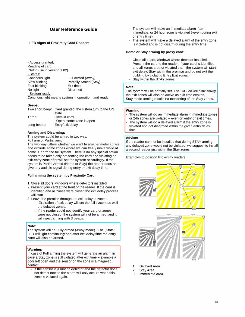
Advice: If the reader can not be installed that during STAY arming any delayed zone would not be violated, we suggest to install a second reader just within the Stay zones. Examples to position Proxymity readers:
1. Delayed Area 2. Stay Area 3. Immediate area

15
General Warnings:
If Your mobile phone or SIM card is carried out from your control you should change ARM DISARM commands from an other pre-authorized, programmed telephone number, or call your installer or Monitoring Station to remotely change settings of your system.
If your proximity card is carried out from your control you should change ARM DISARM commands from an other pre-authorized, programmed telephone number, to disable the proximity reader or call your installer or Monitoring Station to remotely change settings of your system.
HEAD OFFICE - National Sales - Research and Development - Warehouse 9 Hannabus Place, McGraths Hill, NSW 2756, Australia Phone: +61 2 4577 4708 Fax: +61 2 4577 4885 8:30am - 5:00pm (Mon-Fri)