GSM-R Radio Guidance on GSM-R Cell Planning Consultation Iss 1.pdf · GSM-R Radio Guidance on GSM-R...
36
GSM-R Radio Guidance on GSM-R Cell Planning Consultation NS-GSM-R-CELL-9501 Issue 1 19 December 2007 Uncontrolled When Printed
Transcript of GSM-R Radio Guidance on GSM-R Cell Planning Consultation Iss 1.pdf · GSM-R Radio Guidance on GSM-R...
GSM-R Radio
Guidance on GSM-R Cell Planning Consultation
NS-GSM-R-CELL-9501 Issue 1 19 December 2007
Uncontrolled When Printed

NS-GSM-R-CELL-9501 Issue 1 Page 1 of 36 19 December 2007
Contents 1) Introduction......................................................................................................................2 2) Purpose ...........................................................................................................................2 3) Scope ..............................................................................................................................2 4) Responsibilities................................................................................................................2 5) Definitions and Abbreviations ..........................................................................................3
5.1 Abbreviations.................................................................................................................3 5.2 Definitions......................................................................................................................3
6) References ......................................................................................................................3 7) Requirements of Standards.............................................................................................4 8) Recommended Consultation Process .............................................................................6 9) Cost Benefit Analysis.......................................................................................................8 10) Guidance on Network Configuration............................................................................9
10.1 GSM-R Coverage ....................................................................................................9 10.2 Railway Emergency Calls (REC) ...........................................................................10 10.3 Shunting Emergency Calls ....................................................................................20
11) Other issues to consider ............................................................................................21 11.1 Urgent Point-to-Point calls, Standing at Signal Pre-defined Texts, DSD Alarms, Calls from Unregistered trains and Train Describer Failure ..............................................21 11.2 Other Group Call types ..........................................................................................21 11.3 Broadcast Calls......................................................................................................21
Appendix 1 –Cell Planning Design Principles........................................................................23 Appendix 2 – Example Cell Plan Overview Map ...................................................................27 Appendix 3 – Example Detailed Cell Plan Map - Mobile Originated REC Area ....................28 Appendix 4 – Example Cell Plan Map - Signaller Originated REC Areas .............................29 Appendix 5 – Example Cell Plan Map – Operations Control Originated REC Areas ............30 Appendix 6 – Cost Benefit Analysis Methodology & Criteria .................................................31
Uncontrolled When Printed

NS-GSM-R-CELL-9501 Issue 1 Page 2 of 36 19 December 2007
1) Introduction The arrangement of GSM-R network cells is crucial to the optimisation of railway operation under GSM-R. As a requirement of Railway Group Standard GE/RT8080 and the Network Change processes, Network Rail are obliged to consult affected Train Operators on the arrangement of these cells. This is because the arrangement of cells will have a direct impact on the safety benefit offered by GSM-R and on train service performance, particularly as trains will be required to stop following receipt of a Railway Emergency Group Call and await further instruction.
This consultation will also be required from time-to-time when infrastructure changes take place that affect the GSM-R configuration, for example the addition of a new connection, the decommissioning of signal boxes following re-signalling etc.
2) Purpose This document outlines the proposed consultation process for GSM-R cell planning and Group call areas.
It also proposes a suite of cell design proposals and provides guidance on GSM-R network cell configuration issues that should be considered when undertaking the consultation.
3) Scope This document includes cell design and consultation associated with Railway Emergency Calls initiated by:
• Drivers using Cab Mobiles
• Signallers using a Fixed Terminal
• Operations Control using a Fixed Terminal The routing of calls is not covered in this document as this is defined in the GSM-R Operations Concept (Ref 1). Shunting Emergency Group Call configuration is yet to be addressed by the Network Rail GSM-R Project team and hence is not included in this issue, and will be covered by a later issue of this document.
4) Responsibilities 4.1 The responsibility for cell configuration rests with the Network Rail GSM-R project.
4.2 Network Rail is required to consult on the GSM-R cell plan arrangements with affected Train Operators. For the national implementation of GSM-R this will form one aspect for agreement with Train Operators as part of GSM-R Network Change Notice 5 (NCN5).
4.3 Train Operators should review the cell plan data and assess the likely impact on their business as part of this consultation phase and respond accordingly to the Network Rail GSM-R project.
4.4 Network Rail Route Operations should also be reviewing the cell plan data and assess the likely impact on their business as part of this consultation phase and respond accordingly to the Network Rail GSM-R project.
Uncontrolled When Printed
NS-GSM-R-CELL-9501 Issue 1 Page 3 of 36 19 December 2007
4.5 Regarding changes to the GSM-R cell plan subsequent to national roll-out of GSM-R, Train Operators should be informed by means of a specific Network Change Notice issued by Network Rail.
5) Definitions and Abbreviations 5.1 Abbreviations CUI Capacity Utilisation Index
DSD Driver’s Safety Device
eLDA enhanced Location Dependant Addressing
ECO Electrification Control Operator
GSM-R Global System for Mobile communication - Railways
LDA Location Dependant Addressing
OPS Operational Handportable
REC Railway Emergency group Call
TD Train Describer
5.2 Definitions Broadcast Call Area Defined cells over which a Broadcast Call will be transmitted to
mobiles
Cell GSM-R coverage provided by a single base station
Controlling Signaller The Signaller who has responsibility for a specific section of route
Group Call Area Defined cells over which a Group Call will be transmitted to mobiles
Mobiles GSM-R Cab radios and operational handportables
Neighbour List A list of GSM-R cells that it is permitted to transfer an ongoing call in one cell to another cell
Railway Emergency A specific group call following which all drivers in receipt must Group Call bring their train to a stand.
6) References Ref [1] GSM-R Concept of Operations, RSSB, RSSB-GSMR-OC Issue 1, 14 December
2006
Uncontrolled When Printed
NS-GSM-R-CELL-9501 Issue 1 Page 4 of 36 19 December 2007
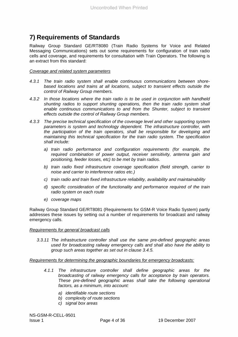
7) Requirements of Standards Railway Group Standard GE/RT8080 (Train Radio Systems for Voice and Related Messaging Communications) sets out some requirements for configuration of train radio cells and coverage, and requirements for consultation with Train Operators. The following is an extract from this standard: Coverage and related system parameters 4.3.1 The train radio system shall enable continuous communications between shore-
based locations and trains at all locations, subject to transient effects outside the control of Railway Group members.
4.3.2 In those locations where the train radio is to be used in conjunction with handheld shunting radios to support shunting operations, then the train radio system shall enable continuous communications to and from the Shunter, subject to transient effects outside the control of Railway Group members.
4.3.3 The precise technical specification of the coverage level and other supporting system parameters is system and technology dependent. The infrastructure controller, with the participation of the train operators, shall be responsible for developing and maintaining this technical specification for the train radio system. The specification shall include:
a) train radio performance and configuration requirements (for example, the required combination of power output, receiver sensitivity, antenna gain and positioning, feeder losses, etc) to be met by train radios.
b) train radio fixed infrastructure coverage specification (field strength, carrier to noise and carrier to interference ratios etc.)
c) train radio and train fixed infrastructure reliability, availability and maintainability
d) specific consideration of the functionality and performance required of the train radio system on each route
e) coverage maps Railway Group Standard GE/RT8081 (Requirements for GSM-R Voice Radio System) partly addresses these issues by setting out a number of requirements for broadcast and railway emergency calls. Requirements for general broadcast calls
3.3.11 The infrastructure controller shall use the same pre-defined geographic areas used for broadcasting railway emergency calls and shall also have the ability to group such areas together as set out in clause 3.4.5.
Requirements for determining the geographic boundaries for emergency broadcasts:
4.1.1 The infrastructure controller shall define geographic areas for the broadcasting of railway emergency calls for acceptance by train operators. These pre-defined geographic areas shall take the following operational factors, as a minimum, into account:
a) identifiable route sections b) complexity of route sections c) signal box areas
Uncontrolled When Printed

NS-GSM-R-CELL-9501 Issue 1 Page 5 of 36 19 December 2007
d) signaller control areas e) intensity of train service f) service group patterns g) tunnels and viaducts.
4.1.2 The infrastructure controller shall be able to group together the pre-defined
geographic groups to enable railway emergency calls to be transmitted to larger areas, if necessary.
4.1.3 The infrastructure controller shall design and configure the GSM-R system so that trains on adjacent, but unconnected routes, do not unnecessarily receive emergency calls that are not applicable to them.
Uncontrolled When Printed

NS-GSM-R-CELL-9501 Issue 1 Page 6 of 36 19 December 2007
8) Recommended Consultation Process It is proposed that consultation on cell design and group call arrangements should be undertaken in two stages. This is because of the inevitable differences between coverage predicted using theoretical methods and that achieved in practice. The first consultation stage will be based on the predicted GSM-R cell coverage and the second stage will furnish data on the ‘as built’ network which may turn out to be slightly different to the predicted coverage.
8.1 General Requirements
8.1.1 Consultation on GSM-R cell design should be undertaken under the provisions of the agreed industry Network Change process.
8.1.2 The consultation dates should be built into Network Rail’s GSM-R detailed Migration Plan for each route, and be undertaken in sufficient time to influence the construction of infrastructure equipment.
8.1.3 The Network Rail GSM-R Project team should document an ongoing process to cater for future changes to the network such as re-signalling, new track layouts etc. which may impact on the original cell configuration.
8.1.4 To enable a comprehensive response to the proposals, it’s important that the cell plans provided for review show the cell arrangement for cells covering routes connecting into the main routes under consideration as these will also impact either directly or indirectly on the train service. Experience with the Strathclyde Trial cell plan so far has shown that a piecemeal approach line-by-line is less efficient as additional reviews of existing cell arrangements would be necessary once the detail of adjacent cells and group call areas are added.
8.2 Stage 1
8.2.1 The Network Rail GSM-R project should develop the proposed cell configuration details based on a set of engineering and operating design rules (see Appendix 2), and present this in a format suitable for review by the Train Operators and Network Rail Route Operators. The presented data should include a series of questions to which answers are being sought by the Network Rail GSM-R, along with sufficient data on which the operators can provide informed comments on.
8.2.2 The initial cell design proposal should be issued separately to the affected train operators and to the affected Network Rail Route Operations for independent review. This should be supported by a presentation by the Network Rail GSM-R project team on how to interpret the data and what specific issues require consideration. This initial proposal is based on predicted cell coverage.
8.2.3 The affected Train Operators and Network Rail Route Operations should review the data and submit a written response to the Project on what is proposed, answering the questions posed, and identifying the specific safety and performance issues that they believe to require review/amendment, stating the reasons why, e.g. excessive service disruption.
8.2.4 The Network Rail GSM-R project should reconcile the various train operator and Network Rail Route Operations comments, and, if necessary, convene a joint meeting with the affected parties to discuss the issues raised, propose amendments and reach agreement on the proposed cell plan and group call areas. Where agreement cannot be reached, then the normal Network Change provisions will apply.
Uncontrolled When Printed
NS-GSM-R-CELL-9501 Issue 1 Page 7 of 36 19 December 2007
8.2.5 Proposed changes should be subject to cost benefit analysis undertaken by the Network Rail GSM-R Project team.
8.2.6 The agreed proposed cell plans will then be used to build (or modify) the GSM-R infrastructure.
8.3 Stage 2
8.3.1 Once the GSM-R network is built in accordance with the agreed design cell plan and group call areas, the Network Rail GSM-R Project team should measure the actual GSM-R coverage and update the cell plans to show the actual best server cell arrangement. The actual arrangement should then be compared to the predicted cell coverage which formed the initial consultation data.
8.3.2 Any material changes between the predicted and actual coverage that would affect the cell arrangement should be presented to the affected Train Operators and Network Rail Route Operations, in order that the impact on safety benefit and train performance can be re-assessed.
8.3.3 The Network Rail GSM-R project should reconcile the various Train Operator and Network Rail Route Operations comments, and, if necessary, convene a joint meeting with the affected parties to discuss the issues raised, propose amendments and reach agreement on the proposed cell plan and group call areas. Where agreement cannot be reached, then the normal Network Change provisions will apply.
8.3.4 Proposed changes should be subject to cost benefit analysis undertaken by the Network Rail GSM-R Project team.
8.3.5 The agreed proposed cell plans will then be used to modify the GSM-R infrastructure built.
Uncontrolled When Printed
NS-GSM-R-CELL-9501 Issue 1 Page 8 of 36 19 December 2007
9) Cost Benefit Analysis The initial cell design will be undertaken by Network Rail GSM-R Project against the cell design principles contained in Appendix 1. One principle objective of cell design is to provide minimum infrastructure necessary (i.e. as few base stations etc.) to support safe and efficient railway operation. Each base station not only increases the cost but also increases issues such as planning permissions. However, increasing coverage of base station increases the potential disruption to train services should a REC occur.
Should cell plan consultation propose that changes are required, either new base stations or modifications to the base station arrangement, then the engineering possibilities and costs of these should be considered against the business costs of potential service disruption following a REC.
Appendix 6 outlines the methodology and criteria to be used when conducting a cost benefit analysis to determine whether additional, or modified, cell designs are justified.
Uncontrolled When Printed

NS-GSM-R-CELL-9501 Issue 1 Page 9 of 36 19 December 2007
10) Guidance on Network Configuration The design of the GSM-R infrastructure network, via the cell configuration, has a number of important safety and performance issues to address. The cell design/group call area arrangement determines:
• the locations where GSM-R coverage is available for normal train operations and train preparation;
• the locations where GSM-R coverage is available for Shunting using GSM-R handportables and cab mobiles;
• the locations where GSM-R coverage will support cab mobile maintenance activities. In this context, coverage should be available inside maintenance depots to support radio testing and not just within the external confines of the depot area;
• the extent of protection afforded/disruption caused by a REC initiated by Drivers;
• the extent of protection afforded/disruption caused by a REC from a Signaller or Route Operations Controller;
• the extent of protection afforded for a Shunting Emergency group call;
• which Signallers and Route Controller will be included in a REC (there is a technical limitation of 5 Fixed Terminals in a REC);
• which Signaller will be the ‘Nominated Signaller’ to deal with
o Urgent Point-to-Point calls (Yellow Button) initiated by Drivers in non-eLDA areas with multiple signallers mapped to the cell;
o single button ‘Call Signaller’ calls erroneously made by Drivers in a non-eLDA with multiple Signallers mapped to the cell;
o single button ‘Standing at Signal’ calls erroneously made by Drivers in a non-eLDA with multiple Signallers mapped to the cell;
o DSD Alarms from trains in non-eLDA areas with multiple Signallers mapped to the cell, and from unregistered trains in any area;
o Calls in eLDA areas where Train Describer information is no longer available.
• the extent of coverage for normal Group Calls;
• the extent of coverage for General Broadcast calls. To assist in designing a cell arrangement that addresses these concerns, a set of operating and engineering design principles will be used by the Network Rail GSM-R Project team (see Appendix 1). The remainder of this document provides guidance against the issues listed above to aid operators in determining the implications of the proposed cell design on their business activities (similar issues are arranged under the same heading).
10.1 GSM-R Coverage The arrangement of GSM-R base station cells determines what radio coverage will be available and where. The signal strength/availability etc. must, as a minimum, comply with the requirements mandated in the GSM-R European standards. The alignment of cells is principally linear along a ‘line of route’ and any coverage of locations adjacent to the line of route (e.g. sidings, depots etc.) may require specific cells to provide adequate network coverage.
Uncontrolled When Printed

NS-GSM-R-CELL-9501 Issue 1 Page 10 of 36 19 December 2007
10.1.1 the locations where GSM-R coverage is available for normal train operations and train preparation
Network Rail GSM-R Project will provide maps of the railway showing the predicted ‘best server’ cell arrangement for Stage 1 consultation, as predicted by their cell mapping software. Updated maps will be provided as part of Stage 2 consultation once the infrastructure has been built and the actual coverage measured. An example of the overview maps is shown in Appendix 3. Signaller boundaries are shown by the straight red lines.
The railway route is coloured to show which GSM-R base station provides coverage on that section of route. In the Appendix 3 example, cell 5111 (blue) provides coverage from Milngavie to just before Westerton Junction, cell 5112 (yellow) provides coverage from Westerton Junction to Hyndland Junction and on towards Yoker and Partick.
The routes shown in grey are considered ‘off the route’ under consideration, but will impact on the route in question where they feed in.
The cell plan consultation map will explicitly show detailed coverage at sidings and yards (or other such locations) where GSM-R train preparation takes place. For train preparation, coverage will be needed in relevant yard/sidings/depots at all points where trains are prepared and radios would be expected to be tested and/or set up prior to departure. This should also consider avoiding the need to draw forward to an exit signal, for example, before the radio could be set up, thus blocking access/egress to the yard/sidings while GSM-R radio set up takes place. It will be necessary for operators to ensure that all such locations are provided with coverage to support the train preparation activities.
Note that during the migration phase to GSM-R, it will be possible for the GSM-R cab radio to be set up at train preparation locations where coverage does not exist (using the ‘Pre-registration’ functionality) in order that when arriving later on at the operational GSM-R boundary point, a simple action is required by the driver to register GSM-R, enabling this to be done ‘on the move’ if necessary.
10.1.2 the locations where GSM-R coverage is available for Shunting using GSM-R handportables and cab mobiles
Again, the cell plan consultation map should explicitly show detailed coverage at sidings, depots and yards (or any other location) where shunting using GSM-R handportables and cab radio may be required.
10.1.3 the locations where GSM-R coverage will support cab mobile maintenance activities. In this context, coverage needs to be inside maintenance depots to support cab radio testing, and not just within the external confines of the depot
Coverage at maintenance locations will be needed for cab radio testing, so assurances should be sought that sufficient coverage will be available to support this testing, e.g. down to the buffer stops inside a maintenance shed. Specific test equipment will be available (Portable Maintenance Unit) but some activities will require a GSM-R network to be available. Again, the cell plan consultation map will be explicit in identifying coverage at maintenance depots as shown in the adjacent example.
10.2 Railway Emergency Calls (REC) The GSM-R Railway Emergency Call (REC) functions differently to existing NRN and CSR emergency calls. The REC is a ‘stop all trains’ function (the Rule Book requires drivers to bring their train to a stand on receipt of the REC) and will be sent to all trains in (or entering) defined cells. Which cells are affected (and hence the extent of protection/disruption)
Uncontrolled When Printed

NS-GSM-R-CELL-9501 Issue 1 Page 11 of 36 19 December 2007
depends on whether the call emanates from a GSM-R mobile radio (cab mobile or handportable) or from a Fixed Terminal (Signaller or Route Controller).
The REC is an area-based ‘Group Call’ and hence only cab radios within a pre-defined set of cells (the group call area or ‘service area’) will receive it, and they will only remain in the call whilst on a route covered by these cells. This is unlike a normal point-to-point call which will be maintained wherever the train moves to until terminated. REC Initiated by a Driver For a Driver-initiated REC there is no selection process required at the point of initiating the call other than the Driver pressing the red ‘Emergency’ button. The GSM-R system sets up the Group Call with all trains in the pre-defined cells.
10.2.1 The extent of protection afforded/disruption caused by a Railway Emergency Group call (stop all trains) initiated by a Driver
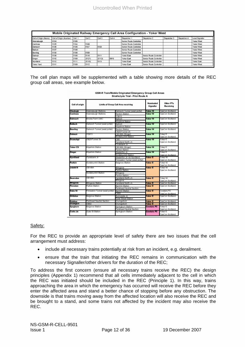
The example map below covers mobile originated calls in Yoker West Signaller’s panel area. The table (enlarged overleaf) shows the ‘Mobile Initiated Railway Emergency Call Area Configuration’ for Yoker West. This identifies the cell in which the REC was initiated, both its name and number (1st and 2nd columns) followed by a series of columns showing which other cells will connect the REC to trains within them. The final columns indicate which other Signaller’s and Operations Controllers will be part of the REC Group Call (note it is planned to provide a single GSM-R Fixed Terminal in each Route Operations Control office). The ‘Lead Signaller’ is the nominated signaller that will receive certain calls that cannot be routed reliably to the controlling signaller.
Uncontrolled When Printed
NS-GSM-R-CELL-9501 Issue 1 Page 12 of 36 19 December 2007
The cell plan maps will be supplemented with a table showing more details of the REC group call areas, see example below.
Safety: For the REC to provide an appropriate level of safety there are two issues that the cell arrangement must address:
• include all necessary trains potentially at risk from an incident, e.g. derailment.
• ensure that the train that initiating the REC remains in communication with the necessary Signaller/other drivers for the duration of the REC;
To address the first concern (ensure all necessary trains receive the REC) the design principles (Appendix 1) recommend that all cells immediately adjacent to the cell in which the REC was initiated should be included in the REC (Principle 1). In this way, trains approaching the area in which the emergency has occurred will receive the REC before they enter the affected area and stand a better chance of stopping before any obstruction. The downside is that trains moving away from the affected location will also receive the REC and be brought to a stand, and some trains not affected by the incident may also receive the REC.
Uncontrolled When Printed

NS-GSM-R-CELL-9501 Issue 1 Page 13 of 36 19 December 2007
As an example, in the map extract below, if a derailment occurred at Westerton Junction, then trains approaching the junction from cells 5112 (yellow), 5110 (red) and 5121 (blue) would need to receive the REC and bring their trains to a stand. To ensure sufficient braking distance then further cells may need to be included as well.
To address the second concern, the design principles for GSM-R cell design (see Appendix 1) recommend that the cell arrangement is configured such that the REC-initiator (initiating Driver) remains in the REC for the entire duration of the REC (Principle 2). To meet this it has been assumed that the Driver initiating the REC will be braking his/her train to bring it to a stand, therefore the minimum ‘distance’ of total cell coverage for the REC-initiator must exceed the braking distance from maximum permitted speed (distance will be based on Railway Group Standards for train braking).
For example, referring to the section of map below, if a Driver were to initiate a call within cell 5111 (Milngavie branch) then cell 5110 would need to be included in the call to ensure the Driver remained in the REC whilst stopping if the REC was made at the south end of the branch close to Westerton Junction.
Uncontrolled When Printed

NS-GSM-R-CELL-9501 Issue 1 Page 14 of 36 19 December 2007
Hence, the cell grouping should be reviewed to ensure that the initiating Driver will still be within the Group Call while bringing the train to a stand.
However, for this arrangement to operate effectively, it is also critical that the names of the cells correspond well with the geographical/local area covered. Operators should consider what has been proposed in the cell area names to ensure that Signallers and Route Controllers will recognise the location from where the REC has been initiated.
Performance: In terms of the effect of a REC on train performance, the REC will have a disruptive effect. This is acceptable where there is a direct and immediate need to bring trains to a stand due to an incident. However, unless carefully designed, the extent of the cell area and grouping (service area) may start to impact unnecessarily on train services not affected by the incident, e.g. on a parallel but unconnected line. Therefore, it is crucial that the effects of a REC are considered carefully during the design stage. To reduce the number of unnecessary trains receiving the REC, opportunities should be considered to:
• change the individual cell design, and/or
• remove cells from the REC group, and/or
• add additional cells. In the example map extract shown below, cell 5112 (yellow) provides significant potential for disruption and will be used to illustrate how the 3 bullet points above might apply:
Scenario 1 – a REC is initiated by a driver at Milngavie after seeing a door open on an adjacent moving train. Applying the design principles in Appendix 2, and assuming that the distance that cell 5110 (red) extends along the Milngavie branch is not sufficient for a train travelling at maximum permitted speed across Westerton Junction to be stopped following receipt of the REC before entering cell 5112 (yellow), then cell 5112 would be included in the REC group for Milngavie. Trains operating from Yoker through to Partick and beyond (unconnected to the Milngavie branch) would be halted as they enter cell 5112. Hence, the scenario would bring all trains to a stand that are in cells 5121 (blue), 5110 (red) and 5112 (yellow). It can be judged from the map that a significant number of trains would be involved and severe disruption would ensue including the time taken to recover the service, all for a problem occurring at Milngavie station area. To resolve this issue, cell 5110 (red) ‘best server’ coverage could be extended far enough along the Milngavie branch such
Uncontrolled When Printed

NS-GSM-R-CELL-9501 Issue 1 Page 15 of 36 19 December 2007
that it provides sufficient braking distance from maximum permitted speed to stop a train entering cell 5111 (blue) from the south or cell 5112 (yellow) from the north Scenario 2 – an incident takes place in Yoker depot covered by cell 5111 (blue) leading to the REC being made by a Driver. The REC would be received by trains in cells 5111 (blue), 5112 (yellow) and 5109 (yellow). With this cell configuration, trains running along the northern side (through Westerton Junction) would be affected by the incident occurring at a location completely off the route they are on. Further, trains from Milngavie to Glasgow would also be affected when they reach cell 5112 (yellow) as would trains entering or exiting this route at Knightswood North on their way to/from Cowlairs. The main problem with this arrangement is the size of cell 5112 which covers several significant junctions and routes. This impact of this could be much reduced by adding another cell to effectively split cell 5112 into two separate cells. This would not alleviate all potential disruption but would reduce disruption significantly around Hyndland Junction if a driver-initiated REC were made from either cell 5110 (red), the unmarked cell leading from Cowlairs or 5121 (blue), if the braking distance through cell 5110 (red) is insufficient. Similarly, this arrangement would reduce disruption around Westerton Junction if a driver-initiated REC were made from either cell 5111 (blue) or 5113 (red). This is a particularly disruptive situation and serves the purpose of illustrating that cell 5112 is too large and affects too many trains. The solution to this, following cost benefit analysis, was to provide an additional cell to reduce the size of cell 5112, as shown in the extract adjacent. Scenario 3 – an incident takes place at Springburn station in cell 5115 (yellow) leading to a driver-initiated REC. Cell 5117 (blue) is the immediate neighbour (although there are connecting lines without coverage shown which will also be affected) and has some ‘spill over’ onto the main route to Hellensburgh due to the cell design/alignment. Thus the emergency at Springburn will bring trains to a stand through Bellgrove Junction and along the branch line. The solution here, shown right, and again subject to cost benefit analysis, was to add a new cell 6020 (yellow) and remove the coverage given by cell 5117 (blue) on the Hellensburgh branch, thus segregating incidents on the Springburn line from the Hellensburgh line.
Uncontrolled When Printed

NS-GSM-R-CELL-9501 Issue 1 Page 16 of 36 19 December 2007
10.2.2 Which Signallers and Route Controller will be included in a Railway Emergency Group call
In the case of a REC initiated by a Driver, it is proposed that every Signaller that has controlling responsibility for trains in a cell included in the REC Group Call Area will be included in the call. Thus more than one Signaller is likely to be involved in the REC.
It is also proposed that the REC will also be received on a single Fixed Terminal in the Network Rail Route Operations Control office.
Note that ECOs will be provided with a Fixed Terminal but would not make or receive REC calls.
The total number of Fixed Terminals that can be configured to receive the REC is 5, hence the decision on which, if any, Signaller’s Fixed Terminals are not included in the call must be agreed (where more than 4 Signallers might meet the criteria).
The table in 11.2.1 above identified which Signaller’s and Route Controller’s are included in the REC depending on the cell the Driver initiates the call in. In this example, for RECs initiated in Yoker West’s cells, only the Yoker West Signallers and the Senior Route Controller will receive the REC.
However, in the table shown below of Glasgow Central Panel 1, Glasgow Central Panels 2, 3 and 4 will also receive the REC. Further consideration is needed as to whether more than one Fixed Terminal need receive the REC when the other signallers are in the same room.
REC Initiated by a Signaller In the case of a REC initiated from a Fixed Terminal, the Signaller or Route Controller (note that the Route Controller might initiate a REC if they are the first to receive a warning about an emergency situation e.g. from the Emergency services) has to make a choice as to where to target the REC.
It’s not possible for a Signaller to target a REC at a single train as with CSR. The Signaller’s Fixed Terminal will have an ‘all area’ service area selection, and then normally 3 further service areas, effectively sub-areas of the ‘all area’, with a maximum of 5 service areas for more complex track layouts. A small number of areas avoids too many choices for the Signaller to make and reduces the risk of error. However, as a result the potential for disruption from a small number of larger areas is much greater, hence this area of the cell design/service area needs addressing carefully.
The Route Operations Controller’s Fixed Terminal will provide the same service area selection as provided to the Signallers for all Signal boxes in their control area.
In the case of a REC initiated by a Signaller, other Signallers that have responsibility for a section of route that is in a cell included in the selected REC Group Call sub-area (or entire Signaller’s area) will be included in the call, as will the Route Operations Controller.
10.2.3 The extent of protection afforded/disruption caused by a Railway Emergency Group call (stop all trains) from a Signaller
Safety: For the Signaller-initiated REC to provide an appropriate level of safety there is only one issue that the cell arrangement must address:
• include all necessary trains potentially at risk from an incident.
Uncontrolled When Printed
NS-GSM-R-CELL-9501 Issue 1 Page 17 of 36 19 December 2007
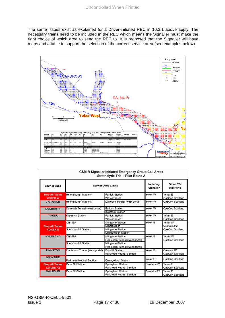
The same issues exist as explained for a Driver-initiated REC in 10.2.1 above apply. The necessary trains need to be included in the REC which means the Signaller must make the right choice of which area to send the REC to. It is proposed that the Signaller will have maps and a table to support the selection of the correct service area (see examples below).
Uncontrolled When Printed
NS-GSM-R-CELL-9501 Issue 1 Page 18 of 36 19 December 2007
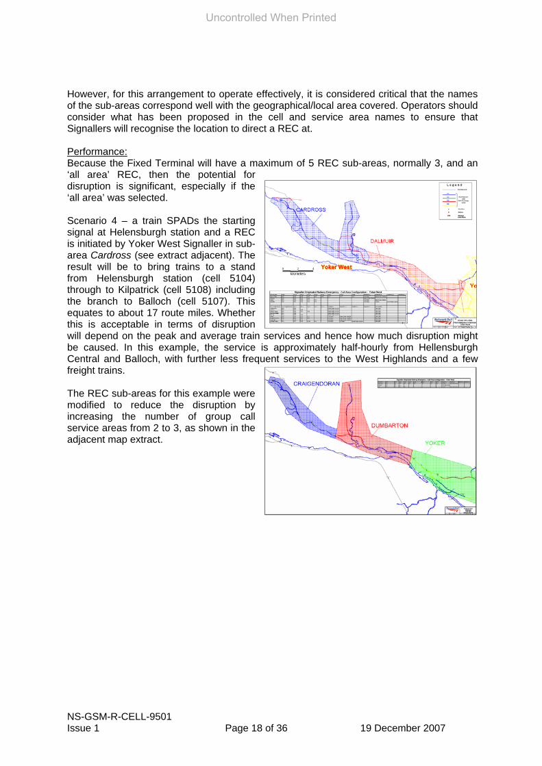
However, for this arrangement to operate effectively, it is considered critical that the names of the sub-areas correspond well with the geographical/local area covered. Operators should consider what has been proposed in the cell and service area names to ensure that Signallers will recognise the location to direct a REC at. Performance: Because the Fixed Terminal will have a maximum of 5 REC sub-areas, normally 3, and an ‘all area’ REC, then the potential for disruption is significant, especially if the ‘all area’ was selected. Scenario 4 – a train SPADs the starting signal at Helensburgh station and a REC is initiated by Yoker West Signaller in sub-area Cardross (see extract adjacent). The result will be to bring trains to a stand from Helensburgh station (cell 5104) through to Kilpatrick (cell 5108) including the branch to Balloch (cell 5107). This equates to about 17 route miles. Whether this is acceptable in terms of disruption will depend on the peak and average train services and hence how much disruption might be caused. In this example, the service is approximately half-hourly from Hellensburgh Central and Balloch, with further less frequent services to the West Highlands and a few freight trains. The REC sub-areas for this example were modified to reduce the disruption by increasing the number of group call service areas from 2 to 3, as shown in the adjacent map extract.
Uncontrolled When Printed

NS-GSM-R-CELL-9501 Issue 1 Page 19 of 36 19 December 2007
REC Initiated by a Route Controller
10.2.4 The extent of protection afforded/disruption caused by a Railway Emergency Group call (stop all trains) from a Route Controller
In the case of a REC initiated by a Route Operations Controller, the Operations Controller has to make a choice as to where to target the REC. The Route Controller will be provided with mapping to support the selection of the correct service area, and that these will be mapped to NRN base station areas also. In the case of a REC initiated by a Operations Controller, other Signallers that have responsibility for a section of route that is in a cell included in the selected REC Group Call sub-area (or entire Signaller’s area) will be included in the REC call. The extract below shows the proposed Operations Controller’s REC service areas for the Strathclyde Trial, and are all the individual Signaller REC Group call areas.
However, for this arrangement to operate effectively, it is considered critical that the names of the service areas correspond well with the geographical/local area covered. Operators should consider the service area names proposed to ensure that Route Operations Controllers will recognise the location to direct a REC at. In the example map above, the table (enlarged extract below) also shows which Signallers are included in the Route Operations Controller-initiated REC depending on which sub-area is selected by the Controlling Signaller.
Uncontrolled When Printed

NS-GSM-R-CELL-9501 Issue 1 Page 20 of 36 19 December 2007
10.3 Shunting Emergency Calls Shunting is a specific mode of GSM-R that is not associated with the normal ‘train mode’ for the cab radio. A specific operational handportable (shunting - OPS) is available that can generate a confidence link tone to control shunting via the GSM-R cab radio. There are two shunting modes, the Common Shunting Group and the Dedicated Shunting Team. In the Common Group, more than one driver could be involved in the group whereas in the Dedicated Team, only one driver can be in this call. Both call types are Group Calls.
10.3.1 The extent of protection afforded for a Shunting Emergency group call; If an REC is generated by the cab mobile when in a Common Shunt Group or a Dedicated Shunt Team, then it will be joined by any other mobile (cab radio or OPS) and Fixed Terminal in the same Common Shunt Group and Dedicated Shunt Teams in the Common Group area. Any cab mobiles in ‘normal train mode’ will not be affected by this call. The cells affected by the Shunting Emergency Group Call are yet to be addressed by the Network Rail GSM-R Project team and are not included in this issue, and are hence not part of this consultation.
Uncontrolled When Printed

NS-GSM-R-CELL-9501 Issue 1 Page 21 of 36 19 December 2007
11) Other issues to consider 11.1 Urgent Point-to-Point calls, Standing at Signal Pre-defined Texts, DSD Alarms, Calls from Unregistered trains and Train Describer Failure In cells which have more than one Signaller mapped to them then it will not always be possible to determine which Signaller a call initiated in that cell should be routed to (note this is not the case for RECs which have to go to all Signallers mapped to the cell). Further, where a Train Describer (TD) system has failed to provide routing information for the call, then eLDA capabilities will be lost. Hence, it is necessary to agree to which Signaller such calls will be routed and this will be shown on the cell arrangement consultation maps as ‘Lead Signaller’.
11.1.1 Which Signaller will be the nominated signaller to deal with Urgent Point-to-Point call (Yellow Button) initiated by a driver in non-eLDA areas with multiple signallers mapped to the cell;
11.1.2 Which Signaller will be the nominated Signaller to deal with a single button ‘Call Signaller’ call from a driver in a non-eLDA with multiple Signallers mapped to the cell;
11.1.3 Which Signaller will be the nominated Signaller for DSD Alarms from trains in non-eLDA areas with multiple Signallers mapped to the cell, and from unregistered trains in any area;
The decision as to which Signaller is nominated to receive such calls may be taken on a number of grounds:
• the Signaller controls the majority of the area covered by the cell; • the call is most likely to occur in a particular location(s) covered by one particular
Signaller; • the Signaller’s workload considerations determine which Signaller should receive
such (rare) calls; • the Signal box is manned 24 hours per day; • a Shift Duty Manager is available to manage the workload.
11.2 Other Group Call types 11.2.1 The extent of coverage of other Group Calls Currently there is no identified operational requirement to hold Group Calls for anything but the REC. However, functionality is within the GSM-R system to do this, set up by a Fixed Terminal. Hence, the cell plan maps do not include any non-Emergency Group Call areas but the service areas will be the same as the REC service areas.
11.3 Broadcast Calls Broadcast calls can be made on an area basis or to defined trains triggering a berth location. In the case of the General Broadcast, the extent of the area needs to be defined.
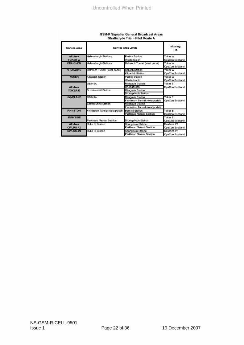
11.3.1 The extent of coverage of Area Broadcast calls The cell plan maps do not specifically show General Broadcast areas as these service areas will be the same as the REC service areas. However, Network Rail will produce a table of General Broadcast Areas as in the example below.
Uncontrolled When Printed
NS-GSM-R-CELL-9501 Issue 1 Page 22 of 36 19 December 2007
Uncontrolled When Printed

NS-GSM-R-CELL-9501 Issue 1 Page 23 of 36 19 December 2007
Appendix 1 –Cell Planning Design Principles The initial cell design undertaken by the Network Rail GSM-R Project will be based on a number of engineering and operating principles, as follows: Principle 1 – All affected trains shall be included in the Railway Emergency group Call. Principle 2 – The initiating driver shall remain in the Railway Emergency group Call for the duration of the call. Principle 3 – Every Signaller and Route Operations Controller that has responsibility for routes covered by the cell(s) shall be included in the Railway Emergency group Call. Principle 4 – An Emergency call initiated in any particular cell shall not be propagated to unaffected trains that are located on lines not covered by the affected cell(s). Principle 5 – Railway Emergency group Call areas presented to Signallers and Operations Route Controllers should be targeted at the minimum number of cells commensurate with providing sufficient protection to the control area but with adequate granularity to avoid excessive disruption. Principle 6 – Signallers and Route Controllers should have systems available to rapidly identify to which GSM-R Railway Emergency group Call area a call should be made. Principle 7 – Wherever possible, cell boundaries shall align with Signaller control areas, particularly in LDA areas, to limit the need for more than one Signaller to be involved in an Emergency call. Principle 8 – Cab radios shall be constrained as far as practical from using cells on unconnected routes. Principle 9 - The number of Railway Group Call areas within each Signallers area of responsibility shall not exceed 5. Principle 10 – Ensure that an overlap of Railway Emergency group Call areas occurs but minimizes disruption to operation. Principle 11 - The Route Operations Controller Railway Emergency group Call areas should align with the Signallers Railway Emergency group Call service areas. Principle 12 - The number of Railway Group Call areas within each Route Operations Controller area of responsibility shall not exceed 24. Principle 13 - The names of the Railway Emergency group Call areas shall be immediately recognisable to the relevant Signallers and Route Operations Controllers. Further explanation and guidance is provided below on each of these principles.
Uncontrolled When Printed

NS-GSM-R-CELL-9501 Issue 1 Page 24 of 36 19 December 2007
Principle 1 – All affected trains shall be included in the Railway Emergency group Call. Signals will be used to stop trains as far as possible and that the primary mitigation from GSM-R is to stop trains that have passed the last controlled signal before the affected area. It is also noted that the operation of the Emergency button by the driver will speed up the process of stopping trains in the affected area.
Affected trains are trains that are at risk of encountering the emergency and may be in neighbouring GSM-R cells and approaching the affected cell at speed, hence neighbouring cells should be included in the REC group call area in all cases to stop any trains approaching the affected cell from outside that cell.
The cell configuration should take account of all possible routes that trains may approach an affected cell from.
Although this would equally stop trains in adjacent cells travelling in the opposite direction (away from the affected cell), it is not considered that exceptions should be made to this rule because this would require a very detailed level of analysis of boundaries and signal positions. This would also be affected by the cell ‘size’ on the day which could be affected by environmental conditions.
Principle 2 – The initiating driver shall remain in the Railway Emergency Group call for the duration of the call. As the REC is a group call, only trains in and remaining in the group call area will continue to receive the call. Hence, if a train exits the group call area it will be dropped from the call. Obviously if this was the initiating driver then the message would not necessarily be completed before it was dropped unless the REC cell area is sufficient to support the duration of the call.
It can be assumed that a driver initiating a REC will be stopping his/her own train. Hence, the distance of travel to be allowed for in cell coverage should reflect braking distance (which may be obtained from Railway Group Standards) from the edge of the affected cell. In essence this is again likely to require the inclusion of the adjacent cells to the affected cell.
Principle 3 – Every Signaller and Route Operations Controller that has responsibility for the route covered by the cell shall be included in the Railway Emergency group Call. As it is not always possible to pinpoint the location from where the REC has been initiated (and the train may be moving at high speed), it is necessary to include all Signallers who are responsible for routes within the cell in order that they may take the appropriate action and are aware of the incident.
Principle 4 – An Emergency call initiated in any particular cell shall not be propagated to unaffected trains that are located on lines not covered by the affected cell or neighbour cell. In this case, the term ‘unaffected cell’ means a cell that trains could continue to operate through and not approach the originating cell that may be affected by the emergency. The reason behind stating this as a principle is to limit the number of trains that are in receipt of the Emergency stop message and are subsequently party to any group call. The more that are involved then the more communications will be required, the more ST messages will be required by the Signaller, the more trains will need to be specifically re-started etc. This is in addition to the disruption effects.
Principle 5 – Railway Emergency group Call areas presented to Signallers and Route Operations Controllers should be targeted at the minimum number of cells
Uncontrolled When Printed

NS-GSM-R-CELL-9501 Issue 1 Page 25 of 36 19 December 2007
commensurate with providing sufficient protection to the control area but with adequate granularity to avoid excessive disruption. It may not be sensible for Signallers and Route Operations Controllers to select individual cells to send a REC to as the number of options may present a complex decision making process. It has been proposed that Fixed Terminals will have the ability for the Signaller/Route Operations Controller to target the REC at their entire area of responsibility or to a few (say 4 or 5) pre-configured ‘sub areas’.
The configuration of these sub-areas must be sufficient to allow coverage of an affected area but not such as to cause extensive unnecessary disruption.
Principle 6 – Signallers and Route Operations Controllers should have systems available to rapidly identify to which GSM-R Railway Emergency group Call ‘sub-area’ a call should be made. Signallers and Route Operations Controllers should be provided with sufficient information to allow them to rapidly determine which ‘sub-areas’ to target a REC to, based on incoming information from external sources (e.g. milepost location) or by reference to signalling panels etc.
Principle 7 – Wherever possible, cell boundaries shall align with Signaller control areas, particularly in LDA areas, to limit the need for more than one Signaller to be involved in an Emergency call. For call routed by eLDA, the call will be routed to the correct signaller with a high degree of reliability. Only in times of TD information failure will routing to the correct Signaller not be possible. For non-eLDA areas the call can only be routed by association with the cell identity. Wherever more than one Signaller has responsibility for a route covered by the cell, then more than one Signaller may need to be assigned to the cell in order to receive calls.
Aligning the cell boundaries to Signaller boundaries has the following advantages:
• It will be possible to target an Urgent call (Yellow Button) from a driver to the Controlling Signaller and avoid a situation where Signallers have to choose between themselves who will answer the call based on TRN;
• It will be possible to enable a single button ‘call signaller’ function in non-eLDA areas.
This is not an issue for Railway Emergency group Calls which will be routed to all Signallers associated with the cell and adjacent cells.
Principle 8 – Cab radios shall be constrained as far as practical from using cells on unconnected routes. Cell design should ensure, as far as possible, that a given line of route is covered by its best servers i.e. cell plan first with appropriate granularity and signal strength then only use neighbour list as a refinement. Need to ensure that at power up the radio camps onto the right cell (note if the intended target cell is weaker than another impingent cell the cab radio will camp on to the stronger of the two i.e. the wrong one). If this then excludes the wanted cell from its neighbour list, the radio will effectively end up following the wrong ‘route’ of cells. It should also not be assumed that the radio will be switched on in the same cell that it was switched off in.
Consideration needs to be given to cell base station failure and any benefits or dis-benefits that preventing use of an adjacent (but unconnected) cell may impart on the train service provision.
Principle 9 - The number of Railway Group Call areas within each Signallers area of responsibility shall not exceed 5.
Uncontrolled When Printed
NS-GSM-R-CELL-9501 Issue 1 Page 26 of 36 19 December 2007
Normally each Signaller’s GSM-R area shall have an ‘all trains stop’ and 3 REC sub-areas. This is to limit the amount of decision making required which would increase with a greater number of areas to choose from. However, in areas of complex layouts, to minimise potential disruption this may be increased to 5 sub-areas.
Principle 10 – Ensure that an overlap of Railway Emergency group Call areas occurs but minimizes disruption to operation. There is a need for REC areas to overlap to ensure trains approaching the area receive the call but that the minimum amount of disruption occurs. This is to avoid the situation of having to make an emergency group call to two adjacent group call areas which would cause unnecessary and severe disruption.
Principle 11 - The Route Operations Controller Railway Emergency group Call areas should align with the Signallers Railway Emergency group Call service areas. The occasions when a Route Operations Controller will be initiating a REC will be when he receives information from a public emergency call. The information relayed to him may not be accurate in railway terms so to allow minimum thinking time and to avoid making a REC in the incorrect area, the REC areas need to be familiar to the route controller and to be relatively large. It is for these reasons that the REC area should align with the signaller’s REC areas.
Principle 12 - The number of Railway Group Call areas within each Route Operations Controller area of responsibility shall not exceed 24. There is a design constraint within the GSM-R fixed terminal which limits the amount of REC areas per Route Operations Controller Fixed Terminal to 24.
Principle 13 - The names of the Railway Emergency group Call areas shall be immediately recognisable to the relevant Signallers and Route Operations Controllers. Each of the group call areas will be given a name in accordance with the signaller control area. These names should be immediately recognisable to the signaller and he should be able to align the name with the geographical area of covered.
Uncontrolled When Printed

NS-GSM-R-CELL-9501 Issue 1 Page 27 of 36 19 December 2007
Appendix 2 – Example Cell Plan Overview Map
Uncontrolled When Printed

NS-GSM-R-CELL-9501 Issue 1 Page 28 of 36 19 December 2007
Appendix 3 – Example Detailed Cell Plan Map - Mobile Originated REC Area
Uncontrolled When Printed
NS-GSM-R-CELL-9501 Issue 1 Page 29 of 36 19 December 2007
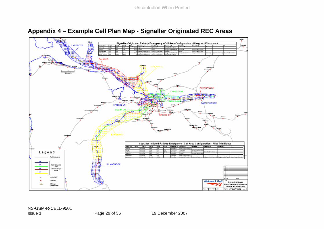
Appendix 4 – Example Cell Plan Map - Signaller Originated REC Areas
Uncontrolled When Printed

NS-GSM-R-CELL-9501 Issue 1 Page 30 of 36 19 December 2007
Appendix 5 – Example Cell Plan Map – Operations Control Originated REC Areas
Uncontrolled When Printed

NS-GSM-R-CELL-9501 Issue 1 Page 31 of 36 19 December 2007
Appendix 6 – Cost Benefit Analysis Methodology & Criteria There are two types of delay caused by a REC, Primary and Secondary delay. The Primary delay is the delay on the trains/section of track where the emergency exists it is not possible to run any trains for the duration of the emergency. Depending on the emergency this could be a very long time resulting in timely and costly delays. The Secondary delay is the delay when trains have been stopped as a result of the REC but are unaffected by the emergency and need not have been stopped. Secondary delays may be lengthened due to the Signaller’s workload in dealing with the emergency. In identifying likely problem locations, the Capacity Utilisation Index (CUI) should be used where available. Values in excess of 70% CUI should point to routes where incidents can rapidly escalate into significant disruptions. To determine whether there is a business case to justify modifying the cell design to either include a new base station or modify the proposed arrangement, the following business case model will be used to determine the relative costs and benefits on a localised basis. The probability of a REC occurring in any cell is the basis of the calculations. An RSSB study showed that every year, over the entire network, there are approximately 1000 emergency calls (NRN and CSR). GSM-R has been specified with an ‘Urgent Call’ function that avoids using the REC in all cases. It has been assumed that in 70% of emergencies the REC will be initiated either by the Driver or the Signaller/Route Controller. This equates to 700 RECs nationally per year across some 2000 GSM-R cells. On average, each cell would have 0.354 RECs per year P(emerg). However, it is recognised that RECs will not be evenly spread across all cells and are more likely to occur in areas prone to vandalism or more likely to suffer a safety of the line incident. Therefore, the analysis should apply judgement to vary the P(emerg) figure of 0.354 by +/– 50%. Also, as any cell requiring review will have adjacent cells included in the REC area then the RECs/cell need to be multiplied by the number of cells. The methodology has been developed based on a probability of a REC being made by a train in a year in the cell area concerned. This is used to work out the probability of an emergency call in a cell by the following equation:
Number of RECs per cell per year = P(emerg) x Number of trains per year in cells
Since we know as a general rule (stated above) there are on average 0.354 emergency calls per cell per year, and since this is obviously not evenly distributed across the cells, we calculated the P(emerg) figure so as to give the correct figure for the area. To work out the number of Secondary delay minutes the following formula is used: Delay minutes = (Number of RECs per cell per year) x (Secondary delay) x (number of delayed trains * ratio delay trains per hour : assumed delay per train)
The Secondary delay is taken as a minimum of 30mins per train, but may be varied based on local factors for the cell under review. The number of delayed trains is given as a figure per hour from the timetable so, for the purpose of these calculations, is factored by the ratio of delay minutes per train assumed. Care must be taken not to “double count” the delayed trains as this would give inaccurate figures.
Uncontrolled When Printed

NS-GSM-R-CELL-9501 Issue 1 Page 32 of 36 19 December 2007
The number of trains per year is sourced from the relevant timetable. A figure of 18 hours per day is used for the train service but this may depend on local services for the cell under review. The Delay Cost is then worked out as follows: Delay cost = delay minutes × £/min The £/min cost is to be sourced from the agreed Schedule 8 (??) cost for the location under review as this value is operator/location specific. Should the business case be marginal then the business disruption costs (on average 4% of total cost) should be taken into account. Worked Example The problem with cell 5112 is that if there is an emergency call in cells adjacent to it, 2 lines which may be unaffected are stopped giving no alternate route for the trains once they are allowed to run again. See figure 1 below. For example an emergency in cell 5110 will stop (according to design principles) 5112 which will stop the Westerton to Cowlairs line (where the emergency is) but will also stop the Clydebank Dock Junction to Finnieston East Junction line which is the line which would most likely be used as an alternate route to get trains moving as quickly as possible and reducing the amount of delay minutes/cost.
Fig 1 - Current cell arrangement for cell 5112
Proposed Scenario A This scenario shows the cell being split (see Fig 2 below) to simulate the potential rebuild (i.e. addition of new site) solution. This configuration is compared to the original cell configuration to determine costs and benefits. All the figures can be seen in table 2 below.
Uncontrolled When Printed
NS-GSM-R-CELL-9501 Issue 1 Page 33 of 36 19 December 2007
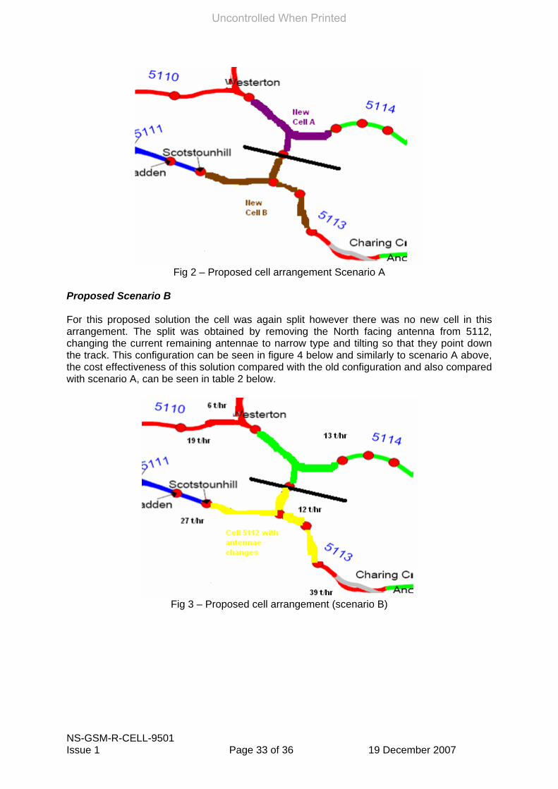
Fig 2 – Proposed cell arrangement Scenario A
Proposed Scenario B For this proposed solution the cell was again split however there was no new cell in this arrangement. The split was obtained by removing the North facing antenna from 5112, changing the current remaining antennae to narrow type and tilting so that they point down the track. This configuration can be seen in figure 4 below and similarly to scenario A above, the cost effectiveness of this solution compared with the old configuration and also compared with scenario A, can be seen in table 2 below.
Fig 3 – Proposed cell arrangement (scenario B)
Uncontrolled When Printed

NS-GSM-R-CELL-9501 Issue 1 Page 34 of 36 19 December 2007
Fig 4 – Number of trains per hour (t/hr) through each section of track (higher than timetable
shows to give a “worst case” scenario)
Assumptions • For scenario A, the cell is split so that the braking distance of the train with the originating
REC is less than the distance travelled in the “new cell A” before entering the second “new cell B”
• For scenario B, the cell split (by making changes to cell 5112) is such that the breaking distance of the train with the originating REC is less than the distance travelled in cell 5114 before entering cell 5112
• Delay cost is £25 per min
• Secondary delay of 60mins per train
Summary of results Scenario A would require the establishment of an additional base station site. A normal site costs £100k. Scenario B, on the other hand, involves some minor work to the existing site.
Cell Arrangement 10 year Delay Cost Reduction
Alteration Cost
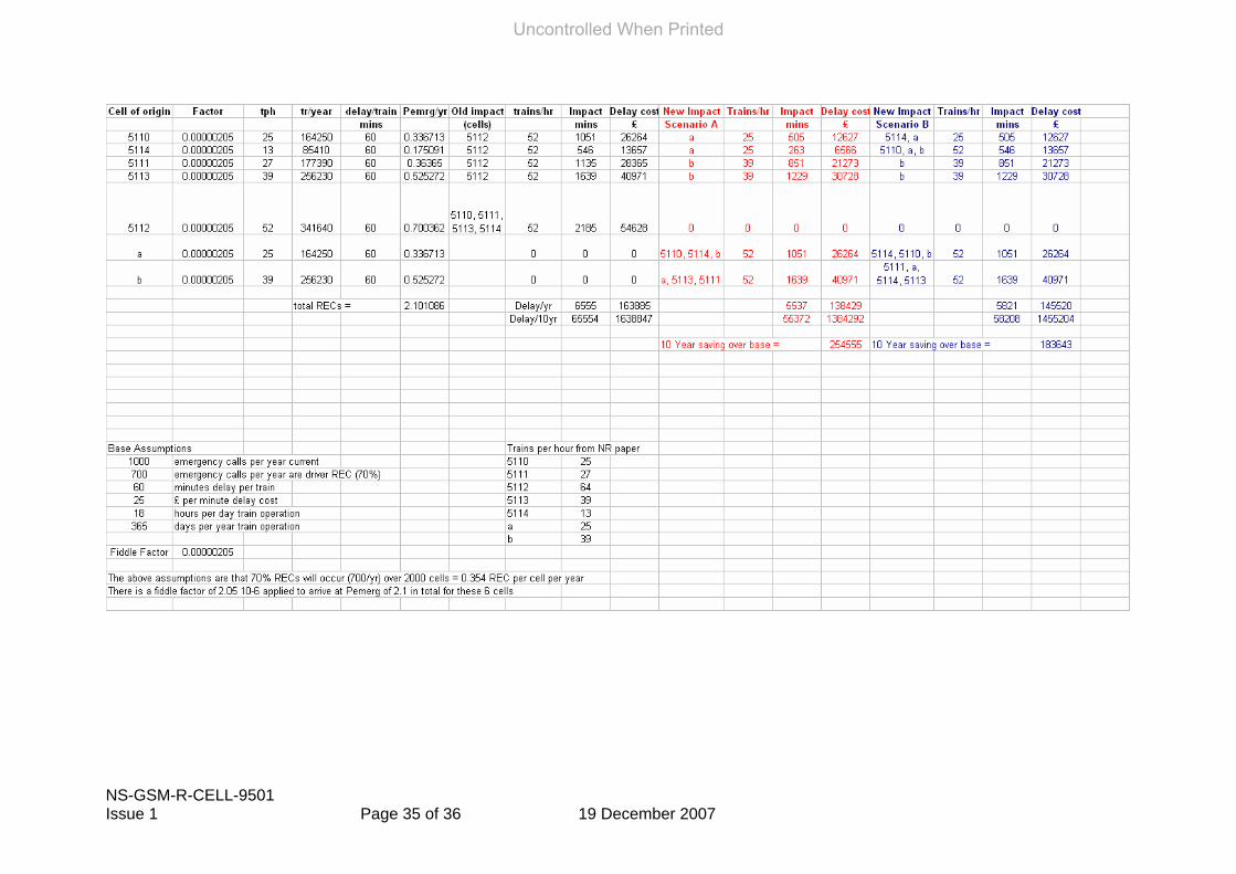
Initial design 0 0 Scenario A £254,555 £100k Scenario B £183,643 Minimal
Scenario A offers a significant saving over the initial design and offers more benefit than scenario B The full calculation is shown on the following spreadsheet.
Uncontrolled When Printed
NS-GSM-R-CELL-9501 Issue 1 Page 35 of 36 19 December 2007
Uncontrolled When Printed