GSM BTS S2000H or S2000L Fundamentals (411-9001-035_18.03)
110
Global System for Mobile Communications (GSM) Nortel GSM BTS S2000H/S2000L Fundamentals Release: V18.0 PC2 Document Revision: 18.03 www.nortel.com 411-9001-035 .
Transcript of GSM BTS S2000H or S2000L Fundamentals (411-9001-035_18.03)

Global System for Mobile Communications (GSM)
Nortel GSM BTSS2000H/S2000L FundamentalsRelease: V18.0 PC2Document Revision: 18.03
www.nortel.com
411-9001-035.

Global System for Mobile Communications (GSM)Release: V18.0 PC2Publication: 411-9001-035Document release date: 13 January 2010
Copyright © 1999-2009 Nortel Networks. All Rights Reserved.
While the information in this document is believed to be accurate and reliable, except as otherwise expresslyagreed to in writing NORTEL PROVIDES THIS DOCUMENT "AS IS" WITHOUT WARRANTY OR CONDITION OFANY KIND, EITHER EXPRESS OR IMPLIED. The information and/or products described in this document aresubject to change without notice.
Nortel, Nortel Networks, the Nortel logo, and the Globemark are trademarks of Nortel Networks.
_ 17+ 18+
All other trademarks are the property of their respective owners.
.

3.
ContentsNew in this release 5Features 5
Introduction 7
Chapter 1 BTS S2000H and S2000L introduction 91.1 S2000H BTS introduction 91.2 S2000L BTS introduction 9
Chapter 2 S2000H and S2000L BTS hardware description 112.1 Physical characteristics 11
2.1.1 Dimensions, weights and power supplies 112.1.2 Mounting plate 122.1.3 Sunshield and cosmetic front panel 122.1.4 Cover 122.1.5 Heatsinks 132.1.6 Internal antennas (S2000L EP BTS only) 152.1.7 DRX heater 162.1.8 Lightning protection 162.1.9 Cooling 172.1.10 Humidity control 172.1.11 Consumption 18
2.2 Physical architecture 182.2.1 S2000H FP BTS 182.2.2 S2000H EP BTS 232.2.3 S2000L FP BTS 282.2.4 S2000L EP BTS 322.2.5 Configurations 40
2.3 Power supply distribution 412.3.1 Power source 412.3.2 Power Supply Units 412.3.3 Battery and Interface Module 42
2.4 BTS cabling 442.4.1 Internal cabling 442.4.2 External cabling 51
Global System for Mobile Communications (GSM)Nortel GSM BTS S2000H/S2000L Fundamentals
411-9001-035 18.03 13 January 2010
Copyright © 1999-2009 Nortel Networks. All Rights Reserved.
.

4
2.4.3 HPRF cabling (S2000H BTS only) 562.4.4 Inter-unit cabling 59
Chapter 3 S2000H and S2000L BTS functional description 613.1 Introduction 613.2 SBCF unit 62
3.2.1 Control and Switching management functions 633.2.2 Data Signaling Concentration unit (DSC) function 663.2.3 PCM management function 673.2.4 Synchronization (SYNC) function 693.2.5 Alarm collecting (ALCO) function 69
3.3 SALCO board 703.4 DRX board 71
3.4.1 DRX logical part 713.4.2 DRX radio part 843.4.3 DRX shutting down 85
3.5 RF module 863.5.1 Common parts 863.5.2 S2000H specific parts 863.5.3 S2000L EP specific part 96
3.6 Internal buses 983.6.1 FH bus 983.6.2 Private PCM bus 98
Chapter 4 S2000H and S2000L BTS software description 1014.1 Software presentation 101
4.1.1 Downloadable files 1014.1.2 Flash EPROMs 101
4.2 Software functions 1024.2.1 DRX software functions 1034.2.2 SBCF software functions 1064.2.3 TIL software functions 107
Global System for Mobile Communications (GSM)Nortel GSM BTS S2000H/S2000L Fundamentals
411-9001-035 18.03 13 January 2010
Copyright © 1999-2009 Nortel Networks. All Rights Reserved.
.

5.
New in this releaseThe following section describe what is new in this release for Nortel GSMBTS S8006 Troubleshooting (411-9001-035) for V18.0 P&C 2 release.
• “Features” (page 5)
FeaturesThis document contains no feature updates in this release.
Global System for Mobile Communications (GSM)Nortel GSM BTS S2000H/S2000L Fundamentals
411-9001-035 18.03 13 January 2010
Copyright © 1999-2009 Nortel Networks. All Rights Reserved.
.

6 New in this release
Global System for Mobile Communications (GSM)Nortel GSM BTS S2000H/S2000L Fundamentals
411-9001-035 18.03 13 January 2010
Copyright © 1999-2009 Nortel Networks. All Rights Reserved.
.

7.
IntroductionThis technical document describes the S2000H and S2000L basetransceiver stations (BTS), one of the Nortel portfolio BTSs.
PrerequisitesThe readers must be familiar with the following technical documents:
• Nortel GSM BSS Documentation Roadmap (411-9001-000)
• Nortel GSM BSS Overview (411-9001-001)
Navigation• Chapter 1 “BTS S2000H and S2000L introduction” (page 9) introduces
the S2000H and S2000L BTSs.
• Chapter 3 “S2000H and S2000L BTS functional description” (page61) examines BTS functional architecture and describes the physicalstructure focusing on the functional architecture of the subsystems.
• Chapter 4 “S2000H and S2000L BTS software description” (page101) names the software entities in the BTS and shows how they areinstalled on the hardware units.
Global System for Mobile Communications (GSM)Nortel GSM BTS S2000H/S2000L Fundamentals
411-9001-035 18.03 13 January 2010
Copyright © 1999-2009 Nortel Networks. All Rights Reserved.
.

8 Introduction
Global System for Mobile Communications (GSM)Nortel GSM BTS S2000H/S2000L Fundamentals
411-9001-035 18.03 13 January 2010
Copyright © 1999-2009 Nortel Networks. All Rights Reserved.
.

9.
Chapter 1 BTS S2000H and S2000Lintroduction
1.1 S2000H BTS introductionThe S2000H BTS is a fully featured BTS (Base Transceiver Station) ideallysuited for coverage of terrain such as highways and rural environments. Itssmall packaging simplifies the site acquisition process thereby improvingthe operator’s time to market and reducing the number of sites requiredby up to 50% as compared to the industry standard. There are two typesof S2000H:
• S2000H FP (First Packaging)
• S2000H EP (Enhanced Packaging)
In the S2000H FP, the main module and the RF supply module aredelivered separately and associated during installation procedure to formthe base module.
In the S2000H EP, the devices of the main modules and the RF supplymodule are mounted in the same enclosure, in factory, to form amonopackaging base module.
1.2 S2000L BTS introductionThe enhanced S2000L offers about three times the capacity of a singletransceiver micro BTS. Its small size allows for swift deployment as part ofa microcellular underlay, providing a solution for traffic hot spots as well asin-building or campus coverage. There are two types of S2000L:
• S2000L FP (First Packaging)
• S2000L EP (Enhanced Packaging)
The S2000L is made of a main module comprising the DRXs and theSBCF, and a LPRF module which contains the RF components. TheS2000L offers two connectors for external antennas (diversity is possible).
Global System for Mobile Communications (GSM)Nortel GSM BTS S2000H/S2000L Fundamentals
411-9001-035 18.03 13 January 2010
Copyright © 1999-2009 Nortel Networks. All Rights Reserved.
.

10 Chapter 1 BTS S2000H and S2000L introduction
The S2000L Single Feeder (SF) offers only one connector, the twotransmission paths are combined (diversity is not possible). In the S2000LFirst Packaging (FP) the main module and the LPRF module are deliveredseparately and associated during installation procedure to form the basemodule.
In the S2000L Enhanced Packaging (EP), the devices of the main modulesand the LPRF module are mounted in the same enclosure, in factory, toform a mono packaging base module. S2000L Enhanced Packaging isfully compliant with S2000L first packaging.
Global System for Mobile Communications (GSM)Nortel GSM BTS S2000H/S2000L Fundamentals
411-9001-035 18.03 13 January 2010
Copyright © 1999-2009 Nortel Networks. All Rights Reserved.
.

11.
Chapter 2 S2000H and S2000L BTShardware description
2.1 Physical characteristicsThe S2000H and S2000L BTSs can be installed indoor or outdoor onpoles, antenna mastheads or walls. For more information, see Figure 1"Wall-, pole-, and antenna mast-mounted BTS" (page 13).
2.1.1 Dimensions, weights and power suppliesThe dimensions and weight of the battery and interface module are:
• height : 408 mm (16.1 in.)
• depth : 238 mm (9.4 in.)
Table 1S2000H/L BTS: Dimensions and weight
HPRF S2000H ’FP’ S2000L ’FP’S2000H’FP’S2000L’FP’
S2000H’EP’ 900/
18001900
HPRF’EP’ ST* ST*
S2000L’EP’
Height 740 mm(29.1)
740 mm(29.1)
740 mm(29.1)
790 mm(31.1)
740 mm(29.1)
650 mm(25.6)
740 mm(29.1)
650 mm(25.6)
Width 542 mm(21.3)
542 mm(21.3)
273 mm(10.7)
273 mm(10.7)
273 mm(10.7)
540 mm(21.3)
540 mm(21.3)
540 mm(21.3)
Depth 197 mm(7.6)
197 mm(7.6)
329 mm(13)
329 mm(13)
329 mm(13)
200 mm(7.9)
200 mm(7.9)
200 mm(7.9)
Max wt.of unit
4 kg (75) 32 kg(71)
20 kg(44.1)
20 kg(44.1)
20 kg(44.1)
31.4 kg(69.2)
31.4 kg(69.2)
31 kg(68.4)
Max wt.ofcosmeticpart
4 kg (31) 12 kg(26)
9 kg (20lb)
10 kg(22)
7 kg (15) 10 kg(22.1)
14 kg(30.9)
8 kg (18)
Global System for Mobile Communications (GSM)Nortel GSM BTS S2000H/S2000L Fundamentals
411-9001-035 18.03 13 January 2010
Copyright © 1999-2009 Nortel Networks. All Rights Reserved.
.
12 Chapter 2 S2000H and S2000L BTS hardware description
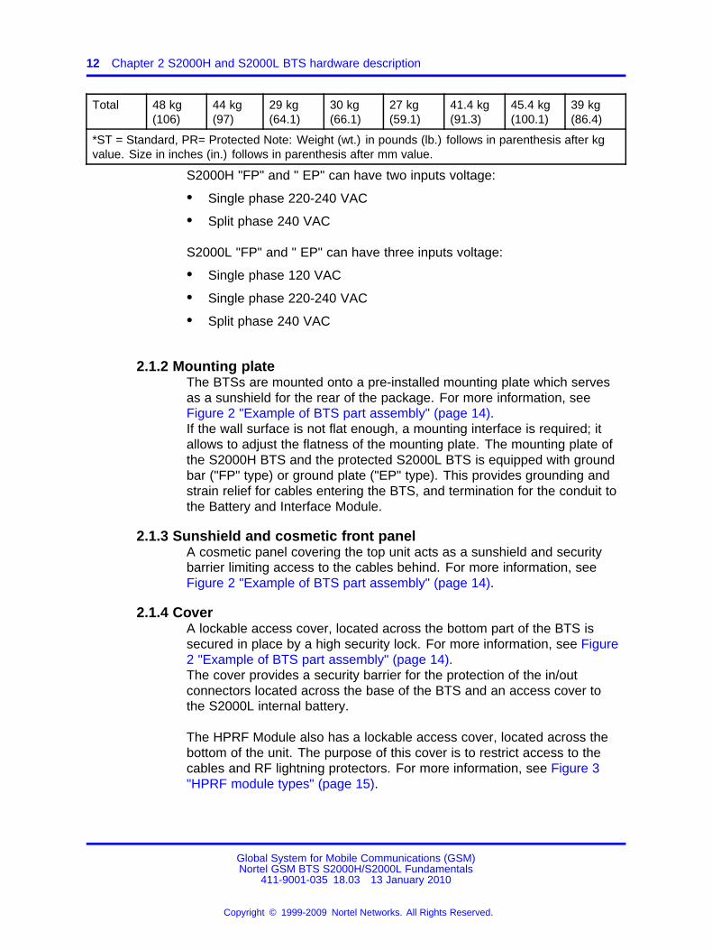
Total 48 kg(106)
44 kg(97)
29 kg(64.1)
30 kg(66.1)
27 kg(59.1)
41.4 kg(91.3)
45.4 kg(100.1)
39 kg(86.4)
*ST = Standard, PR= Protected Note: Weight (wt.) in pounds (lb.) follows in parenthesis after kgvalue. Size in inches (in.) follows in parenthesis after mm value.
S2000H "FP" and " EP" can have two inputs voltage:
• Single phase 220-240 VAC
• Split phase 240 VAC
S2000L "FP" and " EP" can have three inputs voltage:
• Single phase 120 VAC
• Single phase 220-240 VAC
• Split phase 240 VAC
2.1.2 Mounting plateThe BTSs are mounted onto a pre-installed mounting plate which servesas a sunshield for the rear of the package. For more information, seeFigure 2 "Example of BTS part assembly" (page 14).If the wall surface is not flat enough, a mounting interface is required; itallows to adjust the flatness of the mounting plate. The mounting plate ofthe S2000H BTS and the protected S2000L BTS is equipped with groundbar ("FP" type) or ground plate ("EP" type). This provides grounding andstrain relief for cables entering the BTS, and termination for the conduit tothe Battery and Interface Module.
2.1.3 Sunshield and cosmetic front panelA cosmetic panel covering the top unit acts as a sunshield and securitybarrier limiting access to the cables behind. For more information, seeFigure 2 "Example of BTS part assembly" (page 14).
2.1.4 CoverA lockable access cover, located across the bottom part of the BTS issecured in place by a high security lock. For more information, see Figure2 "Example of BTS part assembly" (page 14).The cover provides a security barrier for the protection of the in/outconnectors located across the base of the BTS and an access cover tothe S2000L internal battery.
The HPRF Module also has a lockable access cover, located across thebottom of the unit. The purpose of this cover is to restrict access to thecables and RF lightning protectors. For more information, see Figure 3"HPRF module types" (page 15).
Global System for Mobile Communications (GSM)Nortel GSM BTS S2000H/S2000L Fundamentals
411-9001-035 18.03 13 January 2010
Copyright © 1999-2009 Nortel Networks. All Rights Reserved.
.

2.1 Physical characteristics 13
2.1.5 HeatsinksThe top unit contains all of the environmentally sensitive electronics in anEMC/environmentally sealed enclosure. The heatsinks attached to theenclosure remove heat from the internal modules. For more information,see Figure 2 "Example of BTS part assembly" (page 14).
Figure 1Wall-, pole-, and antenna mast-mounted BTS
Global System for Mobile Communications (GSM)Nortel GSM BTS S2000H/S2000L Fundamentals
411-9001-035 18.03 13 January 2010
Copyright © 1999-2009 Nortel Networks. All Rights Reserved.
.

14 Chapter 2 S2000H and S2000L BTS hardware description
Figure 2Example of BTS part assembly
Global System for Mobile Communications (GSM)Nortel GSM BTS S2000H/S2000L Fundamentals
411-9001-035 18.03 13 January 2010
Copyright © 1999-2009 Nortel Networks. All Rights Reserved.
.

2.1 Physical characteristics 15
Figure 3HPRF module types
2.1.6 Internal antennas (S2000L EP BTS only)Internal antennas are available as an option. They are attached to theinner surface of the sunshield located at the cosmetic front panel. Cablesexiting the base of the antennas connect with the N type connectorslocated at the base of the LPRF Module. The antenna cables andconnectors are concealed and secured behind the lockable access coverlocated across the bottom of the unit.
The system consists of two antennas arranged in an orthogonalcross-polarized arrangement. Each of the two polarizations are inclined at45 degrees to vertical.
Global System for Mobile Communications (GSM)Nortel GSM BTS S2000H/S2000L Fundamentals
411-9001-035 18.03 13 January 2010
Copyright © 1999-2009 Nortel Networks. All Rights Reserved.
.

16 Chapter 2 S2000H and S2000L BTS hardware description
In the downlink direction each polarization is used for transmitting a singlecarrier. This takes advantage of "on air" combining and maximizes thetransmit power by avoiding the normal 3 dB loss of a combiner.
In the uplink direction the orthogonal polarizations provide diversityreception. In a high multipath environment such as those found in urbanindoor and outdoor microcells there is generally a high level of polarizationconversion. As a result the internal antenna system using polarizationdiversity can provide very good diversity performance.
2.1.7 DRX heaterEach DRX is equipped with one silicone rubber heater. This generatesheat to keep the DRX within the operating temperature range in the BTS.This is a resistor connected in series to two thermostats which control theon/off characteristics of the heater. The heater-thermostat is connectedto the AC power supply of the BTS.
The silicone rubber heater has an electrical characteristics of 325 W ± 5%.
2.1.7.1 Heater operationHeaters are ON at start up when the external temperature is below 5�C(+41�F).
When the BTS is operating and the external temperature decreases, theheaters are switched ON at 0�C (+32�F).
When the BTS is operating with the heaters ON and the externaltemperature increases, the heaters are switched OFF at 5�C (+41 �F).
In case of -48V DC external power supply option, the heater is notsupplied.
2.1.8 Lightning protectionThere are three levels of protection:
• The top level of protection is provided by the grounding network,including air terminals and the screening of cables. The mountingplate has a grounding bar to which conduits can be firmly attached.This grounding bar is connected to the electrical ground. Conduits aredeployed between the Battery and Interface Module and the Baseunit while the DC/data cable includes a substantial shield for excellentgrounding.
• The second level of protection diverts unwanted energies on sensitivecircuits to the grounding network or prevents their transmission by useof isolation. It is provided by optional RF lightning protection kits inthe Base unit and by lightning protection devices in the Battery andInterface Module. The protection devices protects the BTS from EMP
Global System for Mobile Communications (GSM)Nortel GSM BTS S2000H/S2000L Fundamentals
411-9001-035 18.03 13 January 2010
Copyright © 1999-2009 Nortel Networks. All Rights Reserved.
.

2.1 Physical characteristics 17
induced on the incoming lines and also on long alarm lines leaving theBTS.
• The third level of protection is the on-board or intrinsic protectiondesigned to meet IEC950 and related specifications. This minimum ofprotection permits the BTS to be deployed without any second levelprotection in certain deployments.
The PRF Supply Module houses a PCP that contains the lightningprotection components for the DC/data cable. The -48V DC lines areprotected on the HPRF PSU itself.
Additional lightning protection for AC power as well as Abis and alarmlines is provided in the Battery and Interface Module.
In case of -48V DC power supply option, every BTS electricalinlet must be protected by the TVSS (Transient Voltage SurgeSuppressors). The TVSS is in accordance with the European andAmerican requirements.
2.1.9 Cooling2.1.9.1 Natural convection coolingThe primary path for the removal of heat from the unit is through thevertical flow of natural convection cooling air over the fins of the externalheatsinks on the front and rear surfaces.
More precisely, the heat path between the PAs and the fins is via heatpipes. Heat pipes are employed in order to reduce the weight of theproduct relative to a conventional aluminum heatsink.
2.1.9.2 SunshieldingTo reduce the effect of sun loading at extreme high ambient temperaturesthe mounting plate is designed to act as a sunshield for the rear and sidesof the housing. The cosmetic panel and cable cover provide sunshieldingfor the front of the housing.
2.1.10 Humidity controlAll BTSs are RHCM BTSs (Relative Humidity Controlled Modules). Thefeatures of this system are as follows:
• Relative humidity is controlled through maintaining a predeterminedtemperature differential between the internal Modules and circuit packsand the ambient temperature.
• The weather resistant enclosure prevents the ingress of liquid orsolid moisture while a diffusion plug (Goretex patch) prevents waterentrapment.
Global System for Mobile Communications (GSM)Nortel GSM BTS S2000H/S2000L Fundamentals
411-9001-035 18.03 13 January 2010
Copyright © 1999-2009 Nortel Networks. All Rights Reserved.
.

18 Chapter 2 S2000H and S2000L BTS hardware description
2.1.11 ConsumptionThe nominal power consumption of the S2000L BTS equipped with twoDRXs and no heater is 250 VA. At low temperatures (typically below 0�
C (+32�F) additional AC power is used for internal heating. The internalheater consumes up to 650 Watts at the low temperature limit of -40�C(-40�F). Thus, the nominal power consumption of the S2000L BTS is inthe worst case. For more information, see Table 2 "S2000L BTS: Powerconsumption" (page 18).
Table 2S2000L BTS: Power consumption
S2000L Maximum power (VA)
102 250
102 and heaters on 900
101 150
101 and heater on 475
The nominal power consumption of the S2000H BTS equipped with twoDRXs is 750 VA (at 70 meters or 230 inches). At low temperatures,typically below 0�C, the S2000H uses additional AC power for internalheating. The internal heater consumes up to 650 Watts at the lowtemperature limit of -40� C (-40�F). Thus, the nominal power consumptionof the S2000H BTS is 1400 VA in the worst case. For more information,see Table 3 "S2000H BTS: Power consumption" (page 18).
Table 3S2000H BTS: Power consumption
S2000H Maximum power (VA)
102/1S11 750
102/1S11 and heaters on 1400
101 400
101 and heater on 725
2.2 Physical architecture2.2.1 S2000H FP BTS
For more information about the S2000H "FP" BTS and its logicalarchitecture, see Figure 4 "S2000H BTS: Line HPRF configuration" (page20) and Figure 5 "S2000H BTS: Star HPRF configuration" (page 21).
Global System for Mobile Communications (GSM)Nortel GSM BTS S2000H/S2000L Fundamentals
411-9001-035 18.03 13 January 2010
Copyright © 1999-2009 Nortel Networks. All Rights Reserved.
.

2.2 Physical architecture 19
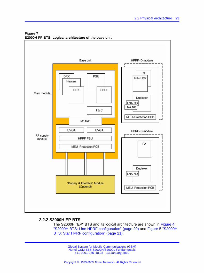
2.2.1.1 Base unitThe base unit contains two parts. For more information, see Figure 6"S2000H FP BTS: Base unit" (page 22) and Figure 7 "S2000H FP BTS:Logical architecture of the base unit" (page 23).
• The first part houses the SBCF (Small Base Common Functions), theDRXs, and the I&C interface and the main PSU (Power Supply Unit).This powers the base unit.
• The second part houses a secondary Power Supply Unit, calledHPRF PSU, that powers the remotable HPRF Modules as well as theVGA/splitters that compensate for RF cable loss and BIM if any.
The I/O field is shared by the two parts.
2.2.1.2 HPRF moduleThis additional package for high RF output power capability houses theRF Power amplifier, LNA, filter (for Dual-RX channel only) and duplexercoupling.
There are two types of HPRF modules:
• The HPRF-S is a Single-RX channel HPRF module. This is used inBTS configurations with two transceivers per cell.
• The HPRF-D is a Dual-RX channel HPRF module. This is used in BTSconfigurations with one transceiver per cell such as O1 and S11. Thesecond RX channel provides diversity reception.
For more information about the HPRF modules, see Figure 7 "S2000H FPBTS: Logical architecture of the base unit" (page 23).
2.2.1.3 Battery and Interface ModuleThis additional package is available as an option. Additional functionalityprovided by this module includes primary lightning protection and bare wiretermination for the AC and PCM (Pulse Code Modulation) alarms inputs.
Global System for Mobile Communications (GSM)Nortel GSM BTS S2000H/S2000L Fundamentals
411-9001-035 18.03 13 January 2010
Copyright © 1999-2009 Nortel Networks. All Rights Reserved.
.

20 Chapter 2 S2000H and S2000L BTS hardware description
Figure 4S2000H BTS: Line HPRF configuration
Global System for Mobile Communications (GSM)Nortel GSM BTS S2000H/S2000L Fundamentals
411-9001-035 18.03 13 January 2010
Copyright © 1999-2009 Nortel Networks. All Rights Reserved.
.

2.2 Physical architecture 21
Figure 5S2000H BTS: Star HPRF configuration
Global System for Mobile Communications (GSM)Nortel GSM BTS S2000H/S2000L Fundamentals
411-9001-035 18.03 13 January 2010
Copyright © 1999-2009 Nortel Networks. All Rights Reserved.
.

22 Chapter 2 S2000H and S2000L BTS hardware description
Figure 6S2000H FP BTS: Base unit
Global System for Mobile Communications (GSM)Nortel GSM BTS S2000H/S2000L Fundamentals
411-9001-035 18.03 13 January 2010
Copyright © 1999-2009 Nortel Networks. All Rights Reserved.
.
2.2 Physical architecture 23
Figure 7S2000H FP BTS: Logical architecture of the base unit
2.2.2 S2000H EP BTSThe S2000H "EP" BTS and its logical architecture are shown in Figure 4"S2000H BTS: Line HPRF configuration" (page 20) and Figure 5 "S2000HBTS: Star HPRF configuration" (page 21).
Global System for Mobile Communications (GSM)Nortel GSM BTS S2000H/S2000L Fundamentals
411-9001-035 18.03 13 January 2010
Copyright © 1999-2009 Nortel Networks. All Rights Reserved.
.

24 Chapter 2 S2000H and S2000L BTS hardware description
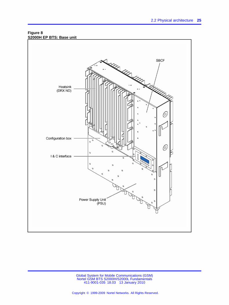
2.2.2.1 Base unitContrary to the S2000H "FP" BTS, all elements of S2000H "EP" BTS arefitted in one part. For more information, see Figure 8 "S2000H EP BTS:Base unit" (page 25) and Figure 9 "S2000H EP BTS: Logical architectureof the base unit" (page 26). The base unit houses the same logical partsas base unit of S2000H "FP" BTS except the I/O field.
It also contains a configuration field which provides different configurationsby selecting the right cabling.
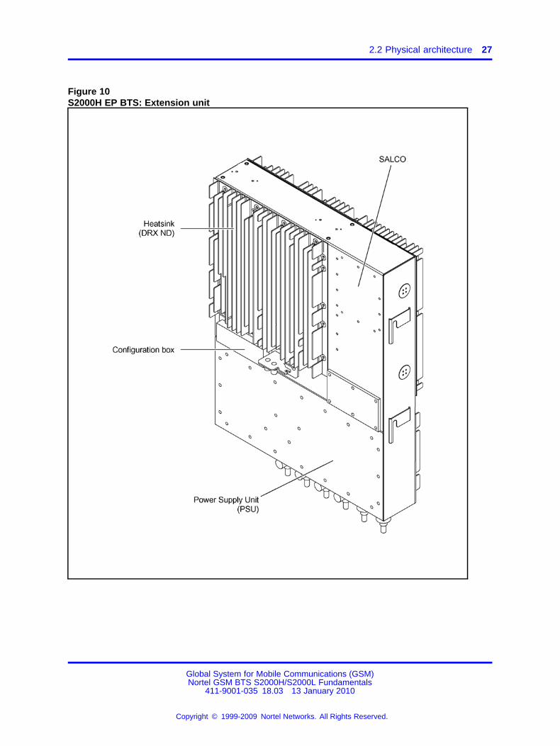
2.2.2.2 Extension unitThe logical architecture of the extension unit is identical to the base unitexcept:
• The SBCF and I&C interface are removed.
• The SALCO board is added.
For more information about the logical architecture of the extension unit,see Figure 10 "S2000H EP BTS: Extension unit" (page 27) and Figure 11"S2000H EP BTS: Logical architecture of the extension unit" (page 28).
2.2.2.3 Other modulesAll types of S2000H BTS use the HPRF module and Battery and Interfacemodule.
Global System for Mobile Communications (GSM)Nortel GSM BTS S2000H/S2000L Fundamentals
411-9001-035 18.03 13 January 2010
Copyright © 1999-2009 Nortel Networks. All Rights Reserved.
.
2.2 Physical architecture 25
Figure 8S2000H EP BTS: Base unit
Global System for Mobile Communications (GSM)Nortel GSM BTS S2000H/S2000L Fundamentals
411-9001-035 18.03 13 January 2010
Copyright © 1999-2009 Nortel Networks. All Rights Reserved.
.

26 Chapter 2 S2000H and S2000L BTS hardware description
Figure 9S2000H EP BTS: Logical architecture of the base unit
Global System for Mobile Communications (GSM)Nortel GSM BTS S2000H/S2000L Fundamentals
411-9001-035 18.03 13 January 2010
Copyright © 1999-2009 Nortel Networks. All Rights Reserved.
.
2.2 Physical architecture 27
Figure 10S2000H EP BTS: Extension unit
Global System for Mobile Communications (GSM)Nortel GSM BTS S2000H/S2000L Fundamentals
411-9001-035 18.03 13 January 2010
Copyright © 1999-2009 Nortel Networks. All Rights Reserved.
.

28 Chapter 2 S2000H and S2000L BTS hardware description
Figure 11S2000H EP BTS: Logical architecture of the extension unit
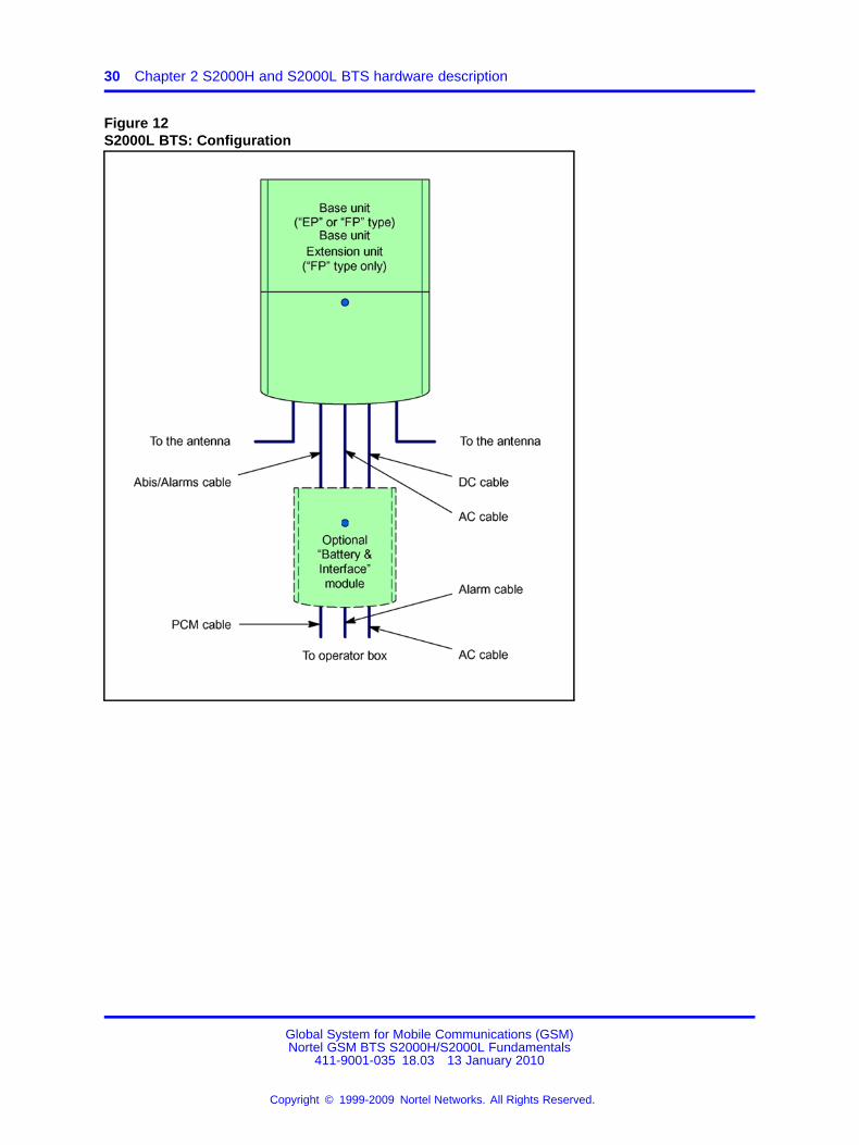
2.2.3 S2000L FP BTSThe S2000L "FP" BTS and its logical architecture are shown in Figure 12"S2000L BTS: Configuration" (page 30).
Global System for Mobile Communications (GSM)Nortel GSM BTS S2000H/S2000L Fundamentals
411-9001-035 18.03 13 January 2010
Copyright © 1999-2009 Nortel Networks. All Rights Reserved.
.

2.2 Physical architecture 29
2.2.3.1 Base unitThe base unit contains the Base Module that can be split up into two parts:
• The first part houses the SBCF, the DRXs, the I&C interface, and themain PSU (Power Supply Unit). This PSU powers the Base Unit andthe BIM if any.
• The second part is the LPRF Module that consists in the couplingsystem (Duplexers, LNAs, and LPAs).
For more information about the Base Module, see Figure 13 "S2000LFP BTS: Base unit" (page 31) and Figure 14 "S2000L FP BTS: Logicalarchitecture of the base unit" (page 32).
The I/O field is shared by the two parts.
However there are two types:
• The "protected S2000L "FP" BTS" which has a ground bar to connectthe external antennas with lightning protectors and/or the conduitsused to link the BTS to the "Battery and Interface" module.
• The "Standard S2000L "FP" BTS" when external antennas are usedwithout lightning protectors (antennas are mounted indoors).
2.2.3.2 Battery and Interface ModuleThis additional package is available as an option. Additional functionalityprovided by this module includes primary lightning protection and bare wiretermination for the AC and PCM alarm inputs.
Global System for Mobile Communications (GSM)Nortel GSM BTS S2000H/S2000L Fundamentals
411-9001-035 18.03 13 January 2010
Copyright © 1999-2009 Nortel Networks. All Rights Reserved.
.
30 Chapter 2 S2000H and S2000L BTS hardware description
Figure 12S2000L BTS: Configuration
Global System for Mobile Communications (GSM)Nortel GSM BTS S2000H/S2000L Fundamentals
411-9001-035 18.03 13 January 2010
Copyright © 1999-2009 Nortel Networks. All Rights Reserved.
.

2.2 Physical architecture 31
Figure 13S2000L FP BTS: Base unit
Global System for Mobile Communications (GSM)Nortel GSM BTS S2000H/S2000L Fundamentals
411-9001-035 18.03 13 January 2010
Copyright © 1999-2009 Nortel Networks. All Rights Reserved.
.

32 Chapter 2 S2000H and S2000L BTS hardware description
Figure 14S2000L FP BTS: Logical architecture of the base unit
2.2.4 S2000L EP BTSFor more information about the S2000L "EP" BTS and its logicalarchitecture, see Figure 12 "S2000L BTS: Configuration" (page 30).
Global System for Mobile Communications (GSM)Nortel GSM BTS S2000H/S2000L Fundamentals
411-9001-035 18.03 13 January 2010
Copyright © 1999-2009 Nortel Networks. All Rights Reserved.
.

2.2 Physical architecture 33
2.2.4.1 Base unitContrary to the S2000L "FP" BTS, all elements of S2000L "EP" BTS arefitted in one part. For more information, see Figure 15 "S2000L EP BTS:Base unit" (page 34) to Figure 17 "S2000L EP BTS single feeder: Logicalarchitecture of the base unit" (page 36). The base unit houses the samelogical parts as base module of S2000L "FP" BTS except the I/O field.
2.2.4.2 Extension unitThe extension unit is identical to the base unit except:
• The SBCF and I&C interface are removed.
• The SALCO board is added.
• In case of single feeder configuration, an 3 dB hybrid combiner isadded.
For more information about the extension unit, see Figure 18 "S2000L EPBTS: Extension unit" (page 37) and Figure 20 "S2000L EP BTS singlefeeder: Logical architecture of the extension unit" (page 39).
2.2.4.3 Battery and Interface moduleAll types of S2000L BTS use the same optional Battery and Interfacemodule.
Global System for Mobile Communications (GSM)Nortel GSM BTS S2000H/S2000L Fundamentals
411-9001-035 18.03 13 January 2010
Copyright © 1999-2009 Nortel Networks. All Rights Reserved.
.

34 Chapter 2 S2000H and S2000L BTS hardware description
Figure 15S2000L EP BTS: Base unit
Global System for Mobile Communications (GSM)Nortel GSM BTS S2000H/S2000L Fundamentals
411-9001-035 18.03 13 January 2010
Copyright © 1999-2009 Nortel Networks. All Rights Reserved.
.

2.2 Physical architecture 35
Figure 16S2000L EP BTS: Logical architecture of the base unit
Global System for Mobile Communications (GSM)Nortel GSM BTS S2000H/S2000L Fundamentals
411-9001-035 18.03 13 January 2010
Copyright © 1999-2009 Nortel Networks. All Rights Reserved.
.

36 Chapter 2 S2000H and S2000L BTS hardware description
Figure 17S2000L EP BTS single feeder: Logical architecture of the base unit
Global System for Mobile Communications (GSM)Nortel GSM BTS S2000H/S2000L Fundamentals
411-9001-035 18.03 13 January 2010
Copyright © 1999-2009 Nortel Networks. All Rights Reserved.
.

2.2 Physical architecture 37
Figure 18S2000L EP BTS: Extension unit
Global System for Mobile Communications (GSM)Nortel GSM BTS S2000H/S2000L Fundamentals
411-9001-035 18.03 13 January 2010
Copyright © 1999-2009 Nortel Networks. All Rights Reserved.
.

38 Chapter 2 S2000H and S2000L BTS hardware description
Figure 19S2000L EP BTS: Logical architecture of the extension unit
Global System for Mobile Communications (GSM)Nortel GSM BTS S2000H/S2000L Fundamentals
411-9001-035 18.03 13 January 2010
Copyright © 1999-2009 Nortel Networks. All Rights Reserved.
.

2.2 Physical architecture 39
Figure 20S2000L EP BTS single feeder: Logical architecture of the extension unit
Global System for Mobile Communications (GSM)Nortel GSM BTS S2000H/S2000L Fundamentals
411-9001-035 18.03 13 January 2010
Copyright © 1999-2009 Nortel Networks. All Rights Reserved.
.

40 Chapter 2 S2000H and S2000L BTS hardware description
2.2.5 ConfigurationsThere are two types of sites:
• Single-cell sites are made up of one SBCF and up to four DRXs.
• Multi-cell sites divide space into sectors where each sectorcorresponds to one cell. They are made up of an SBCF and one ortwo DRXs dedicated to each cell.
For more information about cell sites, see Figure 21 "Single-cell andmulti-cell sites" (page 41).
Configurations for each product are the following. They take into accountthe diversity reception.
Note that the submodules quantities are given only for interest and shouldbe considered as FRUs (Field Replaceable Unit) on no account.
Table 4Configurations for S2000 H/L BTS
S2000H "FP" and"EP" BTS
O1 O2 S11 O4 S22
Base unit 1 1 1 1 1
Extension unit 0 0 0 1 1
DRX (base /extension)
1 / 0 2 / 0 2 / 0 2 / 2 2 / 2
SBCF / SALCO 1 / 0 1 / 0 1 / 0 1 / 1 1 / 1
VGA/Splitter (base /extension)
2 / 0 2 / 0 2 / 0 2 / 2 2 / 2
HPRF module 1 2 2 4 4
PA 1 2*1 2*1 4*1 4*1
LNA 2 2*1 2*2 4*1 4*1
Duplexer 1 2*1 2*1 4*1 4*1
Filter 1 0 2*1 0 4*1
Battery and Interfacemodule *
1 1 1 2 2
(*) The Battery and Interface module is available as an option.
Global System for Mobile Communications (GSM)Nortel GSM BTS S2000H/S2000L Fundamentals
411-9001-035 18.03 13 January 2010
Copyright © 1999-2009 Nortel Networks. All Rights Reserved.
.

2.3 Power supply distribution 41
Table 5Configurations for S2000 BTS
S2000L "FP" and "EP" BTS O1O2/O2
Singlefeeder
O4 S22
Base unit 1 1 1 1
Extension unit 0 0 1 1
DRX (base / extension) 1 / 0 2 / 0 2 / 2 2 / 2
SBCF / SALCO 1 / 0 1 / 0 1 / 1 1 / 1
LPA (base / extension) 2 / 0 2 / 0 2 / 2 2 / 2
LNA (base / extension) 2 / 0 2 / 0 2 / 2 2 / 2
Duplexer (base / extension) 2 / 0 2 / 0 2 / 2 2 / 2
Battery and Interface module * 1 1 2 2
(*) The Battery and Interface module is available as an option.
Figure 21Single-cell and multi-cell sites
2.3 Power supply distribution2.3.1 Power source
The BTSs are powered by AC main voltage.
2.3.2 Power Supply UnitsThe S2000H BTS houses a main PSU and a secondary PSU that powersup to two HPRF Modules and BIM if any.
Global System for Mobile Communications (GSM)Nortel GSM BTS S2000H/S2000L Fundamentals
411-9001-035 18.03 13 January 2010
Copyright © 1999-2009 Nortel Networks. All Rights Reserved.
.

42 Chapter 2 S2000H and S2000L BTS hardware description
The S2000L BTS houses only a main PSU that powers the BIM if any.
The main PSU converts the AC mains voltage into four DC outputs: -48VDC, +5V DC, + 8V DC and +26V DC.
The HPRF PSU converts the AC main voltage into -48V DC output only.
2.3.3 Battery and Interface ModuleThe Battery and Interface Module is an optional box. Located at a shortdistance from the BTS, it provides three main functions to the BTS.
• Termination of utility supply (AC power and Abis connection).
• Location of batteries for backup of BTS.
• Lightning protection circuitry for AC, Abis, and alarm relay lines.
For more information, see Figure 22 "Battery and Interface Module" (page43).
The AC power supply and Abis connection are terminated in the Batteryand Interface Module that provides a demarcation point between the BTSand the site facilities. The Battery and Interface Module is delivered withcables for connection to the BTS; connected cables exit the Battery andInterface Module to interface with the Base Unit. The cable distribution ismade through the Battery and Interface Module. Without this option, thedistribution has to be allowed in another way.
A battery backup pack is located in the Battery and Interface Module. Thisprovides -48V DC voltage to the Base Unit in case of mains power cut.
Additional lightning protection for AC power as well as Abis connection andalarm lines is provided in the Battery and Interface Module.
The separation between the Battery and Interface Module and the unitmust be between and 9.2 meters (between 3.28 and 30.2 ft) due to cablespecifications.
For more information about the Battery and Interface Module dimensions,see Nortel GSM BSS Overview (411-9001-001).
Global System for Mobile Communications (GSM)Nortel GSM BTS S2000H/S2000L Fundamentals
411-9001-035 18.03 13 January 2010
Copyright © 1999-2009 Nortel Networks. All Rights Reserved.
.

2.3 Power supply distribution 43
Figure 22Battery and Interface Module
Global System for Mobile Communications (GSM)Nortel GSM BTS S2000H/S2000L Fundamentals
411-9001-035 18.03 13 January 2010
Copyright © 1999-2009 Nortel Networks. All Rights Reserved.
.

44 Chapter 2 S2000H and S2000L BTS hardware description
2.4 BTS cabling2.4.1 Internal cabling
2.4.1.1 S2000 H/L FP BTSThe connectors of the I/O field carry RF Tx from a DRX, RF Rx (mainand diversity), AC/DC voltage, DC/data interface, VGA control lines, andVGA/LNA alarm lines. For more information, see Figure 23 "S2000H FPBTS: Base unit connectors" (page 45) and Figure 24 "S2000L FP BTS:Base unit connectors" (page 46).
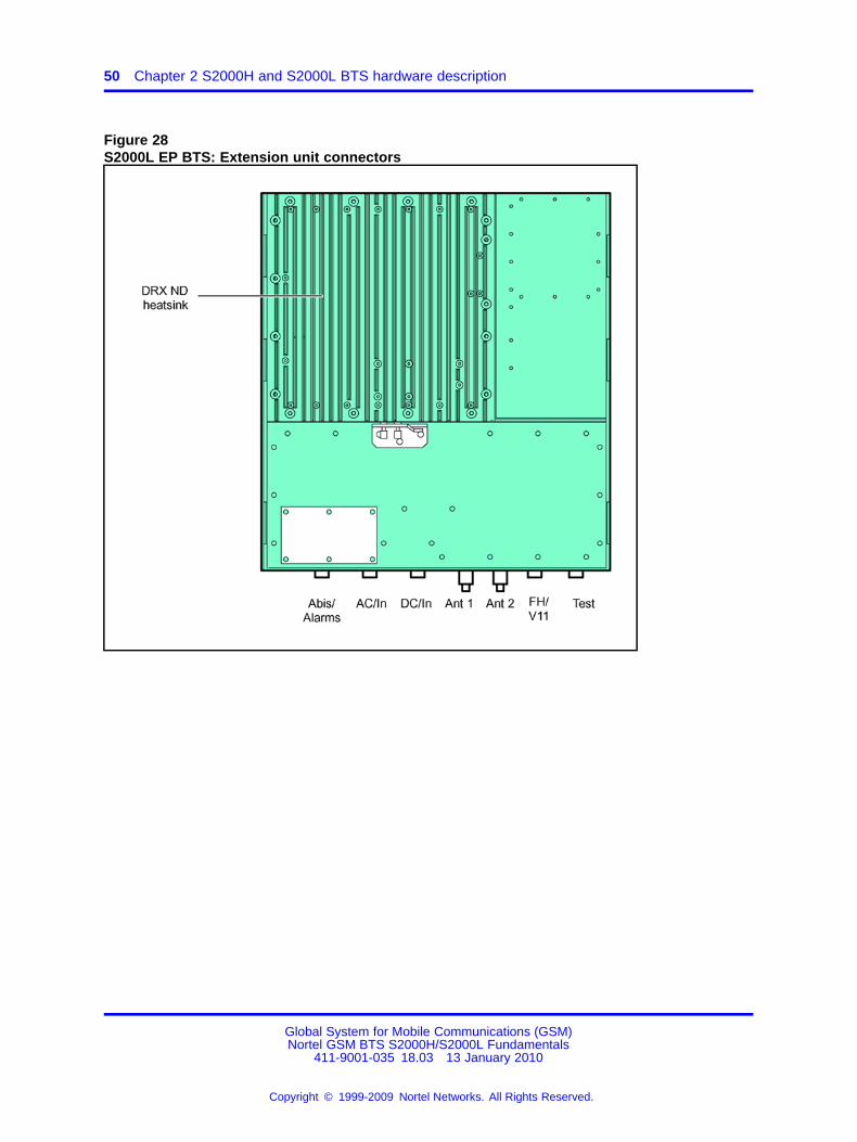
2.4.1.2 S2000 H/L EP BTSThey are designed in one enclosure and do not need I/O field to connectboth modules. For more information, see Figure 25 "S2000H EP BTS:Base unit connectors" (page 47) and Figure 26 "S2000H EP BTS:Extension unit connectors" (page 48).
Only the S2000H "EP" BTS has a cross-configuration area and dependingon the cabling, it provides different configurations. For more information,see Figure 27 "S2000L EP BTS: Base unit connectors" (page 49).
2.4.1.3 Test and Maintenance interfaceThe [Test] is for Test and Maintenance interface which consists of:
• 10Base-T Ethernet connections to each DRX and to the SBCF
• RS232 ports to each DRX and to the SBCF
• frame synchronization pulse outputs from each DRX
The main purpose of the Test and Maintenance interface is for factoryand radio tests. It can be used to troubleshoot BTS problems in the field,although this procedure is expected to be rare. The Base Unit is shippedwith the Test and Maintenance connector sealed by an environmental andEMC cap.
The SBCF Ethernet interface conforms to the TIL interface specification.From this interface it is possible to commission the BTS prior toinstallation, to perform full functional tests and interrogate every entitywithin the BTS for maintenance or trial purposes.
Global System for Mobile Communications (GSM)Nortel GSM BTS S2000H/S2000L Fundamentals
411-9001-035 18.03 13 January 2010
Copyright © 1999-2009 Nortel Networks. All Rights Reserved.
.

2.4 BTS cabling 45
Figure 23S2000H FP BTS: Base unit connectors
Global System for Mobile Communications (GSM)Nortel GSM BTS S2000H/S2000L Fundamentals
411-9001-035 18.03 13 January 2010
Copyright © 1999-2009 Nortel Networks. All Rights Reserved.
.

46 Chapter 2 S2000H and S2000L BTS hardware description
Figure 24S2000L FP BTS: Base unit connectors
Global System for Mobile Communications (GSM)Nortel GSM BTS S2000H/S2000L Fundamentals
411-9001-035 18.03 13 January 2010
Copyright © 1999-2009 Nortel Networks. All Rights Reserved.
.

2.4 BTS cabling 47
Figure 25S2000H EP BTS: Base unit connectors
Global System for Mobile Communications (GSM)Nortel GSM BTS S2000H/S2000L Fundamentals
411-9001-035 18.03 13 January 2010
Copyright © 1999-2009 Nortel Networks. All Rights Reserved.
.

48 Chapter 2 S2000H and S2000L BTS hardware description
Figure 26S2000H EP BTS: Extension unit connectors
Global System for Mobile Communications (GSM)Nortel GSM BTS S2000H/S2000L Fundamentals
411-9001-035 18.03 13 January 2010
Copyright © 1999-2009 Nortel Networks. All Rights Reserved.
.

2.4 BTS cabling 49
Figure 27S2000L EP BTS: Base unit connectors
Global System for Mobile Communications (GSM)Nortel GSM BTS S2000H/S2000L Fundamentals
411-9001-035 18.03 13 January 2010
Copyright © 1999-2009 Nortel Networks. All Rights Reserved.
.
50 Chapter 2 S2000H and S2000L BTS hardware description
Figure 28S2000L EP BTS: Extension unit connectors
Global System for Mobile Communications (GSM)Nortel GSM BTS S2000H/S2000L Fundamentals
411-9001-035 18.03 13 January 2010
Copyright © 1999-2009 Nortel Networks. All Rights Reserved.
.

2.4 BTS cabling 51
Figure 29S2000L EP BTS: Cross-configuration field
2.4.2 External cablingThe incoming cables are distributed by the user interfaces (via the Batteryand Interface Module).
They carry the AC/DC power supply, as well as the Abis connection andthe alarms.
• The AC cable is connected to the customer’s AC panel or to theBattery and Interface Module.
• The DC cable is connected to the battery located in the Battery andInterface Module. For more information on the wiring, see 2.2 “Physicalarchitecture” (page 18).
• The Abis and alarms lines are combined into the Abis cable. Thisis connected to the Battery and Interface Module or the customer’sinterfaces. It carries external PCMs, six alarms and two relays.
For more information, see Figure 30 "S2000H FP BTS: Connector cablingin S11 configuration" (page 52) to Figure 32 "S2000L FP and EP BTS:Connector cabling in O2 configuration" (page 54).
Global System for Mobile Communications (GSM)Nortel GSM BTS S2000H/S2000L Fundamentals
411-9001-035 18.03 13 January 2010
Copyright © 1999-2009 Nortel Networks. All Rights Reserved.
.

52 Chapter 2 S2000H and S2000L BTS hardware description
Figure 30S2000H FP BTS: Connector cabling in S11 configuration
Global System for Mobile Communications (GSM)Nortel GSM BTS S2000H/S2000L Fundamentals
411-9001-035 18.03 13 January 2010
Copyright © 1999-2009 Nortel Networks. All Rights Reserved.
.

2.4 BTS cabling 53
Figure 31S2000H EP BTS: Connector cabling in S11 configuration
Global System for Mobile Communications (GSM)Nortel GSM BTS S2000H/S2000L Fundamentals
411-9001-035 18.03 13 January 2010
Copyright © 1999-2009 Nortel Networks. All Rights Reserved.
.

54 Chapter 2 S2000H and S2000L BTS hardware description
Figure 32S2000L FP and EP BTS: Connector cabling in O2 configuration
2.4.2.1 Abis linkThe external PCM link conforms to the Abis protocol.
Global System for Mobile Communications (GSM)Nortel GSM BTS S2000H/S2000L Fundamentals
411-9001-035 18.03 13 January 2010
Copyright © 1999-2009 Nortel Networks. All Rights Reserved.
.
2.4 BTS cabling 55
The BTSs are in star or in line configuration. The external PCM link can beconnected through the "Battery and Interface" Module.
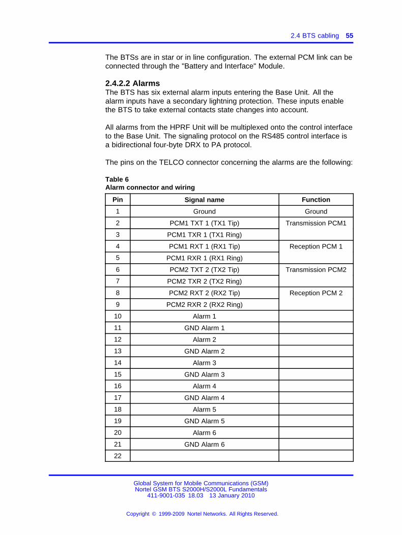
2.4.2.2 AlarmsThe BTS has six external alarm inputs entering the Base Unit. All thealarm inputs have a secondary lightning protection. These inputs enablethe BTS to take external contacts state changes into account.
All alarms from the HPRF Unit will be multiplexed onto the control interfaceto the Base Unit. The signaling protocol on the RS485 control interface isa bidirectional four-byte DRX to PA protocol.
The pins on the TELCO connector concerning the alarms are the following:
Table 6Alarm connector and wiring
Pin Signal name Function
1 Ground Ground
2 PCM1 TXT 1 (TX1 Tip)
3 PCM1 TXR 1 (TX1 Ring)
Transmission PCM1
4 PCM1 RXT 1 (RX1 Tip)
5 PCM1 RXR 1 (RX1 Ring)
Reception PCM 1
6 PCM2 TXT 2 (TX2 Tip)
7 PCM2 TXR 2 (TX2 Ring)
Transmission PCM2
8 PCM2 RXT 2 (RX2 Tip)
9 PCM2 RXR 2 (RX2 Ring)
Reception PCM 2
10 Alarm 1
11 GND Alarm 1
12 Alarm 2
13 GND Alarm 2
14 Alarm 3
15 GND Alarm 3
16 Alarm 4
17 GND Alarm 4
18 Alarm 5
19 GND Alarm 5
20 Alarm 6
21 GND Alarm 6
22
Global System for Mobile Communications (GSM)Nortel GSM BTS S2000H/S2000L Fundamentals
411-9001-035 18.03 13 January 2010
Copyright © 1999-2009 Nortel Networks. All Rights Reserved.
.
56 Chapter 2 S2000H and S2000L BTS hardware description
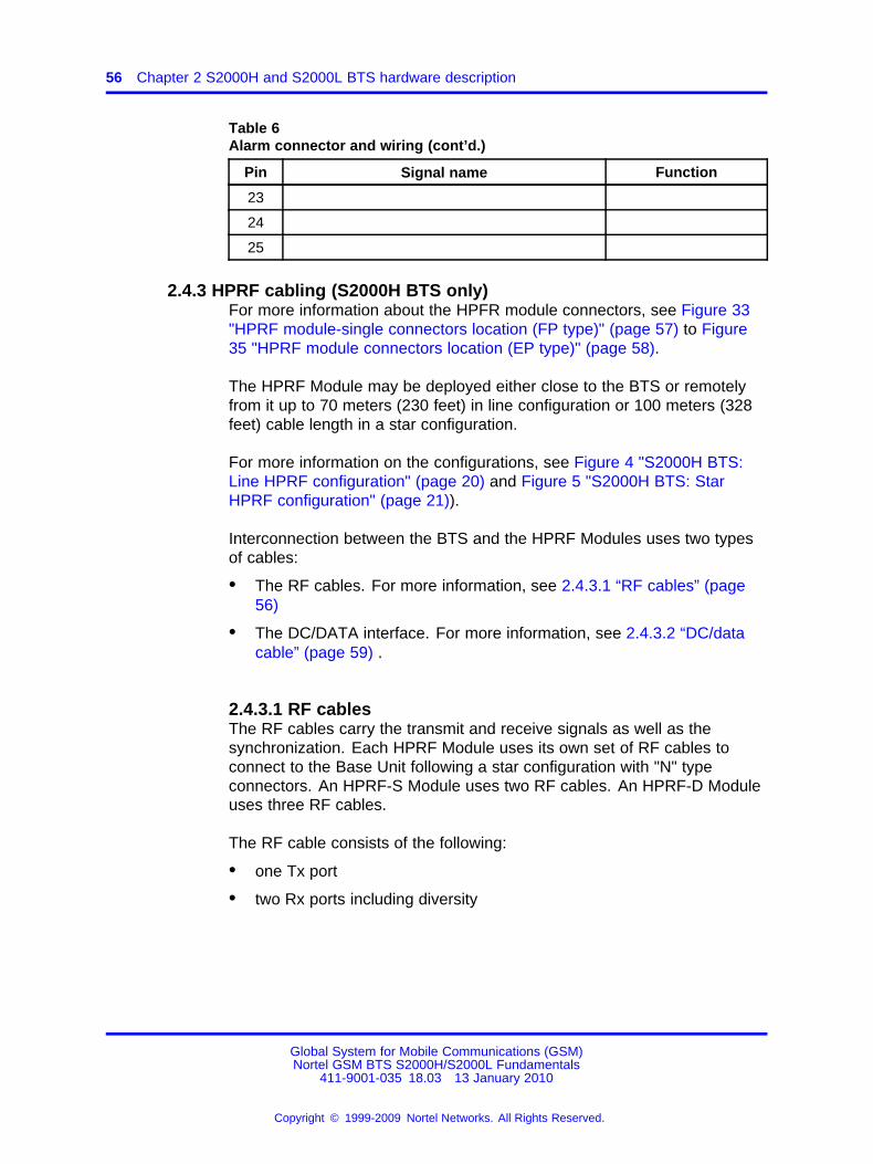
Table 6Alarm connector and wiring (cont’d.)
Pin Signal name Function
23
24
25
2.4.3 HPRF cabling (S2000H BTS only)For more information about the HPFR module connectors, see Figure 33"HPRF module-single connectors location (FP type)" (page 57) to Figure35 "HPRF module connectors location (EP type)" (page 58).
The HPRF Module may be deployed either close to the BTS or remotelyfrom it up to 70 meters (230 feet) in line configuration or 100 meters (328feet) cable length in a star configuration.
For more information on the configurations, see Figure 4 "S2000H BTS:Line HPRF configuration" (page 20) and Figure 5 "S2000H BTS: StarHPRF configuration" (page 21)).
Interconnection between the BTS and the HPRF Modules uses two typesof cables:
• The RF cables. For more information, see 2.4.3.1 “RF cables” (page56)
• The DC/DATA interface. For more information, see 2.4.3.2 “DC/datacable” (page 59) .
2.4.3.1 RF cablesThe RF cables carry the transmit and receive signals as well as thesynchronization. Each HPRF Module uses its own set of RF cables toconnect to the Base Unit following a star configuration with "N" typeconnectors. An HPRF-S Module uses two RF cables. An HPRF-D Moduleuses three RF cables.
The RF cable consists of the following:
• one Tx port
• two Rx ports including diversity
Global System for Mobile Communications (GSM)Nortel GSM BTS S2000H/S2000L Fundamentals
411-9001-035 18.03 13 January 2010
Copyright © 1999-2009 Nortel Networks. All Rights Reserved.
.

2.4 BTS cabling 57
Figure 33HPRF module-single connectors location (FP type)
Figure 34HPRF module-dual connectors location (FP type)
Global System for Mobile Communications (GSM)Nortel GSM BTS S2000H/S2000L Fundamentals
411-9001-035 18.03 13 January 2010
Copyright © 1999-2009 Nortel Networks. All Rights Reserved.
.

58 Chapter 2 S2000H and S2000L BTS hardware description
Figure 35HPRF module connectors location (EP type)
Global System for Mobile Communications (GSM)Nortel GSM BTS S2000H/S2000L Fundamentals
411-9001-035 18.03 13 January 2010
Copyright © 1999-2009 Nortel Networks. All Rights Reserved.
.

2.4 BTS cabling 59
2.4.3.2 DC/data cableThe power and data cable assembly, called DC/DATA cable, interfaces theBTS and the remote or collocated HPRF Modules. For more information,see Figure 4 "S2000H BTS: Line HPRF configuration" (page 20) andFigure 5 "S2000H BTS: Star HPRF configuration" (page 21).
The DC/DATA cable is specially designed for the S2000H BTS to providethe required electrical protection.
The RS485 standard specifies that the voltage levels of a RS485 signalmust not exceed 9 Volts. Thus during a lightning strike, the inducedvoltage levels on the cable must be limited to 9 Volts by a protectioncircuitry (MEU (Masthead Electronics Unit) protection PCB) at each end ofthe interface in the HPRF Unit and the Base Unit.
ConfigurationsThe two configurations are the following:
• Line HPRF configuration:
The first HPRF Module is connected directly to the unit, whereas thesecond module is chained to the first module. For more information,see Figure 4 "S2000H BTS: Line HPRF configuration" (page 20).
• Star HPRF configuration:
The two HPRF Modules are connected to the unit via a splice box.For more information, see Figure 5 "S2000H BTS: Star HPRFconfiguration" (page 21). It allows a parallel DC line cabling whichpermits to reduce the DC line impedance and consequently todecrease the voltage loss on the line.
MEU Protection PCB The MEU Protection PCB is a circuitry requiredto provide protection for three pairs of RS485 differential signals (TX+,TX-, RX+, RX-, SYN+, and SYN-) and one pair of -48 V DC signals. TheMEUHP board located in the HPRF Unit is protection circuitry againstlightning surges and overvoltage on lines and power lines. The MEURFboard located in the RF Supply Module of the Base Unit protects theRF lines while the protection circuitry required for the DC/DATA lines islocated on the secondary PSU of the Base Unit.
2.4.4 Inter-unit cablingAccording to the base unit type, the connection between the base unit("FP" or "EP" type) and the extension unit ("EP" type only) is different. Formore information, see 2.4.1.1 “S2000 H/L FP BTS” (page 44) and 2.4.1.2“S2000 H/L EP BTS” (page 44).
Global System for Mobile Communications (GSM)Nortel GSM BTS S2000H/S2000L Fundamentals
411-9001-035 18.03 13 January 2010
Copyright © 1999-2009 Nortel Networks. All Rights Reserved.
.

60 Chapter 2 S2000H and S2000L BTS hardware description
Global System for Mobile Communications (GSM)Nortel GSM BTS S2000H/S2000L Fundamentals
411-9001-035 18.03 13 January 2010
Copyright © 1999-2009 Nortel Networks. All Rights Reserved.
.

61.
Chapter 3 S2000H and S2000L BTSfunctional description
3.1 IntroductionThis chapter gives a brief description of the functional architecture of theS2000H and S2000L BTSs, but does not detail individual modules. Itshould help the reader to understand the BTS functions discussed in thefollowing chapters.
The S2000H/S2000L BTS contains the following subsystems:
• 3.2 “SBCF unit” (page 62)
• 3.3 “SALCO board” (page 70)
• 3.4 “DRX board” (page 71)
• 3.5 “RF module” (page 86)
• 3.6 “Internal buses” (page 98)
According to the BTS type, the structure of each subsystem is different.For more information, see Figure 36 "Different S2000H and S2000L BTSstructures" (page 62).
The functional architecture of these subsystems and the internal busesare described in this chapter. For more information, see Figure 37 "Basecabinet functional architecture" (page 64).
Global System for Mobile Communications (GSM)Nortel GSM BTS S2000H/S2000L Fundamentals
411-9001-035 18.03 13 January 2010
Copyright © 1999-2009 Nortel Networks. All Rights Reserved.
.

62 Chapter 3 S2000H and S2000L BTS functional description
Figure 36Different S2000H and S2000L BTS structures
3.2 SBCF unitThe SBCF unit is located in the base unit. It enables communication withthe BSC, organizes, stores and broadcasts all the data it receives from theBSC, supervises and uses defense actions on the equipment it controls.
Global System for Mobile Communications (GSM)Nortel GSM BTS S2000H/S2000L Fundamentals
411-9001-035 18.03 13 January 2010
Copyright © 1999-2009 Nortel Networks. All Rights Reserved.
.

3.2 SBCF unit 63
For more information, see Figure 38 "Organization of SBCF functions"(page 65).Two boards make up the SBCF module:
• the SMCF board (small main common functions) does the following:
— Control and Switching Management
— Data Signaling Concentration
— Synchronization
— Alarm collecting
• the SPCMI board (small PCM interface) does the following:
— PCM management
— electrical fail safe requirements
The SPCMI boards provide an electrical fail safe relay control thatguarantees that if the SBCF is not functioning properly, the two externalPCM connections are electrically cross connected. This fail safe ensuresthat failure of one BTS in a daisy chain does not cause the failure of theremaining BTSs in the chain.
3.2.1 Control and Switching management functions3.2.1.1 Setting up communication with the BSCWhen the SBCF is activated, it must be connected to the BSC to work. Alink is set up on an external PCM. Since a number of PCM links unite theBTS and BSC, individual PCM links are frequently polled. If connectionattempts fail on all the available PCMs, the SBCF resets.
3.2.1.2 DownloadingWhen communications have been set up with the BSC, the SBCFreports its status. The BSC downloads the software to the BTS foreach new system release. The SBCF downloadable files are formed bytwo catalogue files (BOOT and DLU), containing the list of the files, aconfiguration file and a file containing BCF code.
3.2.1.3 Synchronization managementAt start-up, the SBCF selects the clock from incoming PCM. During LAPDconnection, the BTS forces the clock onto the PCM carrying the LAPD.
Global System for Mobile Communications (GSM)Nortel GSM BTS S2000H/S2000L Fundamentals
411-9001-035 18.03 13 January 2010
Copyright © 1999-2009 Nortel Networks. All Rights Reserved.
.

64 Chapter 3 S2000H and S2000L BTS functional description
Figure 37Base cabinet functional architecture
Global System for Mobile Communications (GSM)Nortel GSM BTS S2000H/S2000L Fundamentals
411-9001-035 18.03 13 January 2010
Copyright © 1999-2009 Nortel Networks. All Rights Reserved.
.

3.2 SBCF unit 65
3.2.1.4 Switching matrix managementThe switching matrix management includes the following:
• initialization
• configuration
• monitoring/defense
Figure 38Organization of SBCF functions
Each PCM link managed by the switching matrix has the following:
• transmission test interface
• reception test interface
• idle interface
All PCM 0 time slots are connected to PCM 1 time slots to allow PCMlinks to be routed when the BTS are chained together (drop and inserttechnique).
Configuration The switching matrix is configured when the BSCrequests the SBCF to set up or release a signaling or traffic channel.
Signaling channels are set up (or broken off) between a DRX signalingtime slot and a non-concentrated link on the SBCF (It is the SBCF thatactivates the signaling concentration). This may entail (dis)connectionbetween a concentrated link coming from the SBCF and a PCM link timeslot on a PCM interface.
Global System for Mobile Communications (GSM)Nortel GSM BTS S2000H/S2000L Fundamentals
411-9001-035 18.03 13 January 2010
Copyright © 1999-2009 Nortel Networks. All Rights Reserved.
.

66 Chapter 3 S2000H and S2000L BTS functional description
Traffic channels are set up (or broken off) between a DRX traffic time slotand a PCM link time slot on a PCM interface.
3.2.1.5 Transmitter-oriented SBCF defense actionsThe SBCF undertakes defense actions when it receives alarm messagesor when the scanner no longer detects transmitter activity.
If the fault involves a change in DRX state, an event report, with impact, issent to the BSC. If the fault does not involve any DRX state change, anevent report without impact is sent to the BSC.
3.2.2 Data Signaling Concentration unit (DSC) function3.2.2.1 Multiplexing and demultiplexingThe SBCF uses the DSC function to set up communications between theBSC and the other entities that make up the BTS. The LAPD protocolignores the DSC function that serves concentrator and routing functions.
The DSC function reads level 2 addresses (TEI) contained in LAPD framesand, using a routing table, sends the information to another time slot. Thetime slot may be concentrated (a number of TEI arrive) or not (single TEI).
3.2.2.2 Operation and Maintenance functionsConfiguration The SBCF sends the following to the DSC function:
• overall configuration
• connect and disconnect configurations
Overall configuration data includes the following:
• the size of message queues
• two queue overflow thresholds
• The period defining the moment observation messages are sent.
A connection configuration connects a TEI in a single time slot to a secondconcentrated time slot.
Disconnecting may affect a TEI in a single time slot or in a concentratedtime slot.
Disconnecting a concentrated time slot automatically triggersdisconnection of the concentrated TEI it contained.
Global System for Mobile Communications (GSM)Nortel GSM BTS S2000H/S2000L Fundamentals
411-9001-035 18.03 13 January 2010
Copyright © 1999-2009 Nortel Networks. All Rights Reserved.
.

3.2 SBCF unit 67
3.2.2.2.2 Monitoring The DSC function supervises the following events:
• queue overload
• receipt of unexpected frames
• PCM link hardware malfunction
3.2.2.2.3 Fault detection The DSC function receives two thresholdvalues from the SBCF that give the overload situation in messagetransmission queues. When queue thresholds are reached, the DSCfunction issues start and end-of-alarm messages to the SBCF.
3.2.3 PCM management functionThe PCM function interfaces and synchronizes incoming and outgoingPCM links. It converts the external PCM coming from the BSC into internalPCM used by the BTS and also the internal PCM.
Each PCMI handles two external PCM links. The PCM function does thefollowing:
• converts external PCM links into internal PCM for BTS use
• verifies link quality using error detection codes
• matches impedance on the type of PCM link used by the operator
3.2.3.1 ConfigurationThe PCM function operates independently without SBCF involvement.If the PCM function evolves, any SBCF modification is required.Nevertheless, the SBCF sends a configuration message that contains thefollowing:
• the number of erroneous seconds, which defines a window used toevaluate PCM alarms
• threshold M1 for the frame alignment error counters
• threshold M2 for the CRC error counter
• threshold M3 for the coding type error counters
3.2.3.2 MonitoringThe PCM function monitors PCM links and issues fault messagesconcerning PCM alarms.
3.2.3.3 PCM alarm managementManaging PCM alarms involves frame, multiframe, submultiframe, zerotime slot, and frame alignment; CRC is not managed yet.
Global System for Mobile Communications (GSM)Nortel GSM BTS S2000H/S2000L Fundamentals
411-9001-035 18.03 13 January 2010
Copyright © 1999-2009 Nortel Networks. All Rights Reserved.
.

68 Chapter 3 S2000H and S2000L BTS functional description
The TS0 is set aside for the frame alignment signal, multiframe alignmentbits, CRC bits, and alarm sending.
3.2.3.3.1 Frame alignment Frame alignment is operated by the framealignment byte occupying TS0 in every other frame.
Upon loss of frame alignment the alarm bit is set to 1 and the framealignment counter is incremented.
PCM alarms Each PCM alarm corresponds to the detection of oneanomaly type on the PCM reception.
A seriously erroneous second is a second in which an NOS, SIA, RRA, orLOS alarm condition occurred or an FE or CRC counter was overrun.
These alarms are indicated by I&C MMI (Man Machine Interface):
• LOS: frame lock loss signal
Frame lock is considered lost when three consecutive lock signalsare received with errors. This is also the case when bit 2 of TS 0 inframes that contain no locking signal is received three times in a rowwith errors.
• SIA: signal indication alarm
Not used in GSM 1900 frequency bands.
• RRA: remote receive signal alarm
• NOS: no frame signal
Upon detecting the beginning of a NOS fault signal, a 64 kbit/s SIA isgenerated on each TS of the associated internal PCM link, an RRA issent on the external PCM link, and the application associates a NOSerror to the errored second.
• FE: error rate fault signal
Used in case of 2 Mbit/s external PCM link. Error detection is effectedonly in operation without CRC. The application counts the incorrectframe lock words received and compares them with the upper andlower thresholds (programmable).
• CRC: CRC error signal
Not used in GSM 1900 frequency bands.
The quest for CRC multiframe lock is associated with frame lock toensure that the frame lock word found does indeed correspond to asingle lock word to which one can lock permanently.
• SKP: hop indication reception
Not used.
Global System for Mobile Communications (GSM)Nortel GSM BTS S2000H/S2000L Fundamentals
411-9001-035 18.03 13 January 2010
Copyright © 1999-2009 Nortel Networks. All Rights Reserved.
.

3.2 SBCF unit 69
One cause is associated with each seriously erroneous second. The alarmcause is defined in the following descending order of severity: NOS, SIA,LOS, RRA, BER, and CRC.
When the number of seriously erroneous consecutive seconds reachesthe number of erroneous seconds (NBSEC) defined in the configurationmessage, the PCM is designated in a fault condition and a message issent to the SBCF.
The end-of-fault condition is the number NBSEC of consecutive secondswithout errors and the end-of-fault message is sent to the SBCF.
3.2.4 Synchronization (SYNC) functionThe synchronization function must synchronize the DRXs on a singlereference time, GSM time. It supervises the different defense stages.
3.2.4.1 GSM timeThe network supplies the reference time via two PCM links. The SBCFselects one of the two clocks and sends it to the synchronization unit.The clock selected has good long-term accuracy that is why it is used bythe synchronization module that generates reference time for the radiointerface.
If the external reference signal is absent, the SBCF generates the GSMTime. It sends the GSM Time to the DRXs by using the GSM TIMEchannel.
3.2.4.2 MonitoringThe synchronization function is monitored by its own control andmonitoring mechanisms, which check that the unit is operating correctlyand GSM time is available on the GSM TIME bus. The correspondingalarm is a reference clock failure.
3.2.5 Alarm collecting (ALCO) functionThe alarm function collects internal and external BTS alarms.
Internal alarms concern equipment parts on which the SBCF does not useany particular detection action, while external alarms are site-dependent.
These alarms are sent via the ALCO board to the SBCF, which redirectsthem to the BSC and displays them on the I&C user interface.
Global System for Mobile Communications (GSM)Nortel GSM BTS S2000H/S2000L Fundamentals
411-9001-035 18.03 13 January 2010
Copyright © 1999-2009 Nortel Networks. All Rights Reserved.
.

70 Chapter 3 S2000H and S2000L BTS functional description
3.3 SALCO boardThe SALCO board is located in the extension unit. This board collectsalarms that are sent to the base unit via the PCM link which redirects themto the BSC.
It replaces SBCF for management of:
• DRX power supply (according to temperature)
• internal alarms
• heaters
• VGA gain
It provides the following interfaces:
• two DRX FH-PCM interfaces
• two DRX CONFIG interfaces
• PSU fails alarms: DC fail and AC fail
• the ground
• one interface for FH/V11 with the base unit
• one alarm interface for 6 external alarm pairs
• two MEU&RF Alarm/Control/Power interfaces to the HPRF modules
The SALCO board is based on RECAL design:
• microcontroller
• HDLC controller
• static RAM
For more information, see S8000/S8002 BTS Reference Manual, ChapterRECAL board.
Global System for Mobile Communications (GSM)Nortel GSM BTS S2000H/S2000L Fundamentals
411-9001-035 18.03 13 January 2010
Copyright © 1999-2009 Nortel Networks. All Rights Reserved.
.
3.4 DRX board 71
3.4 DRX boardThe DRX board has a logical part and a radio part. For more information,see Figure 39 "DRX architecture" (page 72).
3.4.1 DRX logical partThe DRX logical part is made up of four units:
• AMNU
• DCU8
• BDT
• TX logic
3.4.1.1 AMNU unitThe AMNU unit manages the DRXs.
It manages the eight time slots of a TDMA frame, and the radio signalingfunctions.
These functions can be broken down into operating and maintenancefunctions (O&M) and into radiosignaling function (RSL). For moreinformation, see Figure 40 "AMNU functions" (page 72).
The following Operation and Maintenance functions are processed by theFrame management unit (AMNU):
• start-up, downloading, and initialization
• configuration
• monitoring/defense
Start-up/Downloading/Initialization The AMNU is started by ahardware reset or a reinitialization message sent by the SBCF.
The DRX subsystem can be downloaded only after that the SBCF isdownloaded and that the units of site management, cell management, andAbis signaling of the DRXs have been configured.
Global System for Mobile Communications (GSM)Nortel GSM BTS S2000H/S2000L Fundamentals
411-9001-035 18.03 13 January 2010
Copyright © 1999-2009 Nortel Networks. All Rights Reserved.
.

72 Chapter 3 S2000H and S2000L BTS functional description
Figure 39DRX architecture
Figure 40AMNU functions
The SBCF systematically initiates a downloading phase of the cataloguefiles and of the following software units:
• AMNU
• SPU
Global System for Mobile Communications (GSM)Nortel GSM BTS S2000H/S2000L Fundamentals
411-9001-035 18.03 13 January 2010
Copyright © 1999-2009 Nortel Networks. All Rights Reserved.
.

3.4 DRX board 73
• DLU
• BOOT
• TX
• BDT
• BIST of the SPUs
Follow by a re-flashing of the units for which the software versions aredifferent.
Configuration The DRX is configured by the SBCF by means of anSBCF/DRX link on private PCMs.
Configuration can be broken down into:
• a general configuration:
— configuration of the TDMA frame
• time slot configurations:
— configuration of radio time slots
— configuration of the frequency hop
Configuration of the TDMA frame provides the DRX with parametersshared by the whole cell such as:
• cell identity (BSIC)
• BCCH frequency
• indication of frequency hop implementation
• cell type (normal or extended)
and with parameters specific to the DRX:
• the frequency of the TDMA frame if there is no frequency hopping
• indication of implementation of diversity in reception
The TDMA frame cannot be dynamically configured. A change ofconfiguration requires a re-start of the downloaded software.
The configuration of the radio time slot specifies the type of logical channelto use for a time slot.
The configuration of the frequency hop specifies, for a time slot, the list offrequencies to use as well as sequencing. This configuration is optionaland only appears if the frequency hop was requested in the TDMA frameconfiguration.
Global System for Mobile Communications (GSM)Nortel GSM BTS S2000H/S2000L Fundamentals
411-9001-035 18.03 13 January 2010
Copyright © 1999-2009 Nortel Networks. All Rights Reserved.
.

74 Chapter 3 S2000H and S2000L BTS functional description
Monitoring The SBCF regularly sends status requests to the DRX todetect any problems on the OML link.
LAPD break The LAPD, OML and RSL links are monitored by a timer.If level 2 loss is detected, the BSC and the AMNU try to reconnect. Ifconnection has not been made by the end of the time-out, the AMNU isreinitialized.
Event reports The AMNU collects all events detected by the DRXequipment. It carries out filtration, and reports errors to the BSC.Transmission error reports and fault management on RX-splitters alarmsare sent through the SBCF.
The AMNU filters to prevent repetition of non-transient events, whichmeans it can send the BSC a single indication.
The AMNU sends errors to the BSC by sending "event report" messagesthrough the SBCF. There are two types of these messages:
• transient messages which are not acknowledged by the BSC
• non-transient messages which must be acknowledged by the BSC andwhich are repeated by AMNU until they are acknowledged.
The radio signaling function supports two Signal Processing Units (SPU).Each SPU manages one time slot.
Two versions of the SPU software are available. One correspondsto propagation conditions in rural area and the other to propagationconditions in urban area. For the rural areas the algorithm parameterequals zero where as it is set at the value 0.5 for urban areas in this latercase, the interferer cancellation algorithm is active.
The radio signaling functions can be broken down into four groups offunctions:
• level 1 radio access
• level 2 radio management of LAPDm signaling
• level 3 radio management, which is made up of two functions:
— radio resources management
— radio measurements management
• operation and maintenance
Global System for Mobile Communications (GSM)Nortel GSM BTS S2000H/S2000L Fundamentals
411-9001-035 18.03 13 January 2010
Copyright © 1999-2009 Nortel Networks. All Rights Reserved.
.

3.4 DRX board 75
Level 1 radio access Level 1 radio access makes it possible to managedialogue between the AMNU signaling function and the SPU processorswhich are connected to the AMNU. It offers the following:
• configuration of operating modes for each SPU
• SPU control
• transmission and reception of data on the radio channel, respectingmethods for slaving to the radio frequency.
Level 2 radio management Level 2 radio management manages theLAPDm level 2 signaling on the radio channels.
Radio resources management (radio level 3) Radio level 3 providesthe following functions:
• level 2 management on the common channels
• control of level 2 functions on dedicated channels
• activation of the common channels
• organization of the Common Control CHannel (CCCH) includingchaining and repetition of paging messages and transmission ofdedicated channel allocation messages
• activation or deactivation of dedicated channels, implementation ofciphering and channel mode changes
• providing SPU processors with system information on the SAACH andBCCH channels
• detection of "random access" and "hand over access"
• detection of radio link attenuation (monitoring of the upstream SACCHchannel) verifiable by the OMC
• sending the mobile transmission power change
Radio measurements management (level 3 radio) This provides thefollowing functions:
• return of interference measurements carried out by the SPUprocessors on the inactive dedicated channels and transmission ofthese measurements to the AMNU
• concatenation of measurements made by the SPUs on the activededicated channels and those transferred by the mobile over the sameperiod
Global System for Mobile Communications (GSM)Nortel GSM BTS S2000H/S2000L Fundamentals
411-9001-035 18.03 13 January 2010
Copyright © 1999-2009 Nortel Networks. All Rights Reserved.
.

76 Chapter 3 S2000H and S2000L BTS functional description
Operation and maintenance functions These functions provideconfiguration and de-configuration of the time slots and frequency hoppingfunctions.
3.4.1.2 DCU8 unitThe DCU8 unit consists of an interface sub-unit between the radioreception and the signal processing (ASIC BB-FILT) and the two time slotprocessing submodules each handing four time slots.
ASIC BB-FILT The BB_FILT ASIC constitutes the interface betweenthe signal processing unit of the DRX and the radio RX module onthe one hand and the ciphering ASIC on the other. It carries out theband-pass filtering of the digital samples output by the radio RX moduleand generates the FH bus.
A single BB_FILT ASIC processes all eight TSs of the radio frame.
The functions provided by this ASIC includes the following:
• GSM time reception interface providing the synchronization of theDSPs on the radio frame
• on transmission:
— recording of the TX parameters and of the ciphering key suppliedby the EGAL DSPs
— transfer of the ciphering key to the CHIF ASIC
— reading of the ciphering template from CHIF
— ciphering of the parameters and transmission on the FH bus
• on reception:
— recording of the RX parameters and of the ciphering key suppliedby the EGAL DSPs
— programming of both synthesizers
— generation of channel and sampling frequency selection signalsfor the analog to digital converter
— base-band filtering of the digital samples output by the converter
— selection of the best gain for each channel (normal and diversity)
— transfer of these selected filtered samples to the EGAL DSP
— transfer of the deciphering key to the CHIF ASIC
— reading of the deciphering template from CHIF and transfer of thetemplate to the EGAL DSP
Global System for Mobile Communications (GSM)Nortel GSM BTS S2000H/S2000L Fundamentals
411-9001-035 18.03 13 January 2010
Copyright © 1999-2009 Nortel Networks. All Rights Reserved.
.

3.4 DRX board 77
SPU The SPU carries out processing associated with the transmissionlayer, and to this end, it executes a number of functions, such as:
• demodulation of GMSK signal at reception
• ciphering/deciphering of sent and received data
• coding/decoding and interleaving/de-interleaving of data from thevarious channels
• coding/decoding of voice and data (from 13 kbit/s to 16 kbit/s and alsofrom 16 kbit/s to 13 kbit/s)
• transfer of discontinuous transmission (DTX) signal
• control of transmitters and receivers
For more information, see Figure 41 "SPU reception functions" (page78) and Figure 42 "SPU transmission functions" (page 78).
Demodulation function Demodulation consists of extracting, from theGMSK signal received, the binary data transmitted, that is 144 bits for anormal burst and 36 bits for an access burst. This is done for the eighttime slots of the radio channel.
The demodulation principle selected takes into account the inter-symbolinterference resulting from smoothing of the transmission phase transitions(limitation of the transmitted spectrum), multiple path phenomena, anddistortion introduced by the channel filter upon reception.
Implementation of this type of demodulator requires modification of thetransmission channel concerning pulse response, frequency deviation,and reception times. Determining these parameters is part of the job ofthe demodulation function.
The receiver has the space diversity function. Both received channels arecombined in an equalizer which carries out joint equalization.
For each of these channels, the pulse response as well as the C/I+Nratio are estimated. These ratios are used to weight the predictions andsamples of each channel.
The symbols from the equalizer are then decrypted, de-interleaved anddecoded to restore the control messages and traffic sent by the mobile.
Ciphering/deciphering function The fluxes of binary symbols sent andreceived on each time slot on the TCH or SDCCH are encrypted one bit ata time, in compliance with the ciphering/deciphering algorithm.
Global System for Mobile Communications (GSM)Nortel GSM BTS S2000H/S2000L Fundamentals
411-9001-035 18.03 13 January 2010
Copyright © 1999-2009 Nortel Networks. All Rights Reserved.
.

78 Chapter 3 S2000H and S2000L BTS functional description
The ciphering or deciphering operation protects confidentiality of voice andsignaling. It consists of adding binary bits, one by one, between sent andreceived data and a binary train (the ciphering sequence), generated froma ciphering key and the TDMA frame number of the time slot.
Figure 41SPU reception functions
Figure 42SPU transmission functions
Global System for Mobile Communications (GSM)Nortel GSM BTS S2000H/S2000L Fundamentals
411-9001-035 18.03 13 January 2010
Copyright © 1999-2009 Nortel Networks. All Rights Reserved.
.

3.4 DRX board 79
Coding/decoding and interleaving/de-interleaving functions All trafficand control logic channels are coded to protect useful information againsttransmission errors. Each channel has its own coding scheme usuallyincluding the following steps for each block:
• protection of data bits with parity bits or a block code
• coding of the "data bits + check bits" unit with a convolution code; thisoperation gives coded bits
• rearrangement and interleaving of the coded bits
• burst formatting
For data, the coding procedure depends on the rate. The interleaving levelis higher for data than for voice.
Some channels do not use the coding schemes described above, inparticular the RACH, FCCH and SCH channels, for which interleaving onseveral times slots does not exist.
Mobile transmission timing advance function The BTS must measurethe delay on the received signal when the mobile station makes itselfknown.
This measurement, known as timing advance, is forwarded in thededicated channel assignment message (immediate assignment) to theMS, which uses this parameter to anticipate its transmission timing.
During the call establishment, the BTS computes the timing advance valueand sends it within CHANNEL REQUIRED message to the BSC. If thisvalue is above the threshold, then the BSC rejects the call establishment.
In ongoing call conditions, the timing advance is calculated at regularintervals and sent to the MS over the downlink SACCH channel.
The calculation is based on the following:
• other measurements taken during demodulation
• the timing advance used by the mobile station that is returned in thelayer 1 header of the uplink SACCH
Discontinuous transmission (DTX) Discontinuous transmission allowssignals to be sent over the radio channel alone when a speech signal ispresent. This limits interference and MS power consumption. For eachcall, the MSC indicates whether the BSS "does not use" or "may use" theDTX.
Global System for Mobile Communications (GSM)Nortel GSM BTS S2000H/S2000L Fundamentals
411-9001-035 18.03 13 January 2010
Copyright © 1999-2009 Nortel Networks. All Rights Reserved.
.
80 Chapter 3 S2000H and S2000L BTS functional description
The principle behind discontinuous transmission is as follows:
• The base or mobile vocoder has a Voice Activity Detector (VAD)that detects if the frame constructed every 20 milliseconds containsspeech. If the frame does not contain speech, the vocoder constructs aspecial frame called the SIlence Descriptor (SID) that contains all thebackground noise description elements. This frame is sent to producea comfort noise at the far end and radio transmission stops.
• The vocoder periodically reassesses the ambient noise andreconstructs the SID frame. The frame produced in this way is sent instep with the SACCH (once every four 26-frame multiframes or 480milliseconds)
• When the vocoder detects new speech activity, a special SID frameindicating the End Of Silence (EOS) is sent, and normal speech framesending resumes.
• On the receive end, additional processing sequences interpretthe incoming traffic frame types (speech, SID, and FACCH) usingthe related flags (BFI, SID, and TAF) and perform the appropriateoperations.
• The DTX allows for data in a non-transparent mode.
BCCH filling The BCCH frequency must be transmitted continuously somobile stations can perform field strength measurements in neighboringcells.
Continuous transmission is accomplished in the following ways:
• When frequency hopping is not used, the TRX uses the BCCHfrequency as the carrier frequency for all the channels it supports. TheTRX sends fillers on the BCCH frequency although it may have nothingto send in a given time slot.
• When frequency hopping is being used, one of the following occurs:
— The hopping laws authorize permanent BCCH transmission andall the TRXs help fill operations.
— The hopping laws do not authorize permanent transmission and atransmitter is required to enable BCCH "filling" independently andtake over when the hopping laws step down.
ATTENTIONThe laws that enable permanent transmission on the BCCH are effective onlyfor cavity coupling.
Global System for Mobile Communications (GSM)Nortel GSM BTS S2000H/S2000L Fundamentals
411-9001-035 18.03 13 January 2010
Copyright © 1999-2009 Nortel Networks. All Rights Reserved.
.

3.4 DRX board 81
Transmitter and receiver control The SPU controls a transmitterand a receiver. It calculates the frequency hop law and determines thefrequencies to synthesize.
The transmitter is controlled by the FH bus. The SPU sends the followingto the transmitter:
• the power and frequency to use
• the bits to send
• the time synchronization signal
The SPU sends the following to the receiver:
• the frequency to use for the following time slot
• the synchronization clock signal
• the GSM TIME synchronization signal
The SPU receives the following from the receiver:
• digitized samples from the reception channel
• the scale factor (gain)
• the receiver alarms
Radio measurement processing The Radio Measurement Processingperformed by the BTS ensures that the network and the mobiles cancommunicate with each other with minimum interference at the lowestpossible transmission power and with the best transmission quality.
Measurements processed by the BTS include signal strength and signalquality. The mobile takes measurements in the downlink direction (BTS ?MS), while the BTS takes them in the uplink direction (MS ? BTS). Othermeasurements include signal strength on the BCCH frequency of thesurrounding cells and the MS_BTS distance.
The BTS averages these measurements for each connection. Theaveraged measurements are then used as the basis for a decision-makingprocess for the following:
• power control
• call clearing
• inter-cell handover
• intra-cell handover
Global System for Mobile Communications (GSM)Nortel GSM BTS S2000H/S2000L Fundamentals
411-9001-035 18.03 13 January 2010
Copyright © 1999-2009 Nortel Networks. All Rights Reserved.
.

82 Chapter 3 S2000H and S2000L BTS functional description
The BTS sends the interference measurements done by the inactivechannels to the BSC.
3.4.1.3 BDT unitThe BDT (time base) unit regenerates GSM TIME signals. The GSM TIMEis distributed to the BDT unit of each DRX by means of the GSM TIMEchannel of the private PCM every 60 ms.
The value of the propagation delay is sent to the DRX by means ofthe OML link of the private PCM. From this data, each DRX makes thenecessary corrections and regenerates the GSM TIME bus.
If, for any reason, the GSM time is not distributed on the BDT unit, theBDT unit maintains the GSM TIME bus signals locally and continues toprovide the GSM time to the DRX units.
The BDT unit is made up of a logic block and a calculation block.
Logic block The BDT unit receives a 26 MHz clock signal derived fromthe radio unit clock. This clock signal has the same stability propertiesas the 4Fbit clock signal provided by the BCF synchronization board andis more stable in the short term. The logic block generates the followingsignals:
• H4Fb (clock at four times bit frequency)
• STRTM (recurrent pulse at 577 microseconds)
• TIME_DATA (containing T1, T2, T3, and TN)
Calculation block The calculation block synchronizes the H4Fb andSTRTM signals with the synchronization unit signals of the BCF. Inaddition, it updates the values T1, T2, T3, and TN.
The synchronization principle consists of forcing a divider-by-24 counterto divide by 23 (if the BDT is slow) or by 25 (if it is fast). This way, every23 or 25 periods of 26 MHz (depending on whether the slow BDT isaccelerated or the fast BDT is slowed down), the BDT corrects to 26 MHz.
3.4.1.4 TX logic unitThe main role of the TX logic unit is to control the radio subassembly inreal time. It receives the BCF configuration commands from the AMNU. Itcarries out the processing and sends back reports.
The TX logic unit recognizes two types of power amplifier, PA or LPAdepending on the BTS type. So it knows if any LNA alarms have to beexpected.
Global System for Mobile Communications (GSM)Nortel GSM BTS S2000H/S2000L Fundamentals
411-9001-035 18.03 13 January 2010
Copyright © 1999-2009 Nortel Networks. All Rights Reserved.
.

3.4 DRX board 83
Once configured, the TX logic unit reads, on each time slot, the datapresent on the FH bus. Then it calculates the frequency code and thepower code to be used with the radio interface.
Transmission power In general, radio power is determined by twoinputs. One controls the maximum static power and the other gives thedynamic attenuation at each time slot.
The static power is given by the CSWM in the CONFIG message. The TXcalculates attenuation to compensate for cable loss between the TX-driverand the power amplifier. The compensation coefficient is dynamicallyupdated when the slave loop is initialized. Adjustment sensitivity is 2 dB.
The dynamic power is provided by the ASIC of the TX logical unit. Itssoftware reads the value and commands the TX-driver accordingly.
In the case of a BCCH filler, the additional attenuation introduced is alwayszero.
The power values that the TX and the mobile have to use are fixed by theBTS according to a control algorithm using the measurements results thatit makes and the thresholds stockpiled in the OMC. The mobile and theBTS power control can be inhibited by the OMC.
The power control aim is to minimize the interferences, ensure goodtransmission quality, and save the mobile’s batteries.
Power slaving The setpoint value is slaved to compensate for gainvariations of the transmission chain.
Two slaving loops are used to compensate for attenuation in the gainchain. For more information, see Figure 43 "Power slaving diagram" (page84).
These loops may be in the following states:
• Open: This state is used for calibration of the internal loop with theexternal loop.
• Initialization: This state is used for loop start-up.
• Error: A loop is in error when it is not longer in correspondence withthe setpoint.
• Closed: A loop is closed when it is in slow slaved mode.
Global System for Mobile Communications (GSM)Nortel GSM BTS S2000H/S2000L Fundamentals
411-9001-035 18.03 13 January 2010
Copyright © 1999-2009 Nortel Networks. All Rights Reserved.
.

84 Chapter 3 S2000H and S2000L BTS functional description
3.4.2 DRX radio partThe DRX radio part is made up of three units:
• the Fref reference unit
• the receiver unit
• the transmitter unit
Figure 43Power slaving diagram
3.4.2.1 Reference moduleThe reference frequency for all local oscillators is derived from the Freffrequency supplied by the VCXO, itself derived from the 4.096 MHz signalprovided by the DRX logical part.
3.4.2.2 Receiver unit (RX)The receiver unit (RX) has the following two main functions:
• conversion of the radio frequency band signal to a base band signal
• digitalization of the base band signal
The base band signal is then sent in binary form with its scale factor tothe DRX logical part.
Global System for Mobile Communications (GSM)Nortel GSM BTS S2000H/S2000L Fundamentals
411-9001-035 18.03 13 January 2010
Copyright © 1999-2009 Nortel Networks. All Rights Reserved.
.

3.4 DRX board 85
Receiver configuration The receiver configuration is done by the DRXlogical part, which sends:
• the reception frequency to be used for the following time slot.
• the synchronization clock signal.
• the GSM time synchronization signal.
Receiver monitoring The receiver monitors internal equipment:microprocessor and Phase Lock Loops (PLL).
If there is a failure or other problem, it generates the following alarm:
• microprocessor fault
• frequency range not respected (if the frequency to synthesize asrequested by the DRX logical part is incorrect)
• PLL loss of alignment (if one of the receiver PLLs is not aligned)
3.4.2.3 Transmitter unit (TX)The transmitter unit generates a low-power radio signal which will beamplified by the Power Amplifier (PA). An I/Q quadrature modulator isused to generate the GMSK signal before radio filtering and dynamicpower adjustment.
The radio power to be generated by the transmitter is not constant. Thepower peak can be adjusted by means of the BSC as a function of the sizeof the cells and the set of reusable frequencies. In addition, the powerpeak can vary from one time slot to the other without optimization of theinterface report.
3.4.3 DRX shutting downThe two actions mentioned hereafter can be performed by a uniquecommand for better efficiency in shutting down the DRX.
3.4.3.1 DRX soft blockingThe DRX soft blocking consists in setting a DRX "out of service" withoutstopping the calls established on this DRX. If possible, an intra-cellhandover is performed for those calls to release the DRX more quickly.Otherwise, the DRX will be released after the normal completion of thecalls.
3.4.3.2 DRX soft blocking coupled with a forced handoverTo speed up the DRX shutting down, the DRX soft blocking can becoupled with a forced handover. The calls will be handed over a neighborcell if the signal strength is over the handover threshold for that cell.
Global System for Mobile Communications (GSM)Nortel GSM BTS S2000H/S2000L Fundamentals
411-9001-035 18.03 13 January 2010
Copyright © 1999-2009 Nortel Networks. All Rights Reserved.
.

86 Chapter 3 S2000H and S2000L BTS functional description
3.5 RF moduleThe RF module is the interface between the DRXs and the BTS antennaconnectors. It supports transmit and receive paths.
For more information about the coupling system of the base unit, seeFigure 44 "S2000H FP BTS: Coupling subsystem in O1 configuration"(page 87) to Figure 51 "S2000L EP BTS: Coupling subsystem in O2configuration" (page 94). The coupling system of the extension unit isidentical.
3.5.1 Common partsThe coupling subsystem includes the following:
• duplexers
• Low Noise Amplifiers (LNA)
• Power Amplifiers (PA)
3.5.1.1 DuplexerIt provides the following:
• simultaneous transmission and reception with a single antenna
• filtering for reception and transmission:
— rejection of out-of-band signals on receive path
— attenuation of PA harmonics and spurious on the transmit path
3.5.1.2 LNAThe LNA is a reception amplifier. Its main function is to provideamplification of the weak signals from the receive antenna and set up theoverall system noise figure.
3.5.1.3 PA or LPAThe PA (for S2000H) or the LPA (for S2000L) amplifies the RF transmitsignal originating from the DRX to a level appropriate for transmission.
3.5.2 S2000H specific partsThe additional package for high RF output power capability includes thefollowing:
• UVGA/Splitters (Universal Variable Gain Amplifier)
• RX filters for one DRX/cell configuration
Through the use of UVGA/Splitters and filters, the antennas may beshared for receiver diversity.
Global System for Mobile Communications (GSM)Nortel GSM BTS S2000H/S2000L Fundamentals
411-9001-035 18.03 13 January 2010
Copyright © 1999-2009 Nortel Networks. All Rights Reserved.
.

3.5 RF module 87
Figure 44S2000H FP BTS: Coupling subsystem in O1 configuration
Global System for Mobile Communications (GSM)Nortel GSM BTS S2000H/S2000L Fundamentals
411-9001-035 18.03 13 January 2010
Copyright © 1999-2009 Nortel Networks. All Rights Reserved.
.

88 Chapter 3 S2000H and S2000L BTS functional description
Figure 45S2000H FP BTS: Coupling subsystem in O2 configuration
Global System for Mobile Communications (GSM)Nortel GSM BTS S2000H/S2000L Fundamentals
411-9001-035 18.03 13 January 2010
Copyright © 1999-2009 Nortel Networks. All Rights Reserved.
.

3.5 RF module 89
Figure 46S2000H FP BTS: Coupling subsystem in S11 configuration
Global System for Mobile Communications (GSM)Nortel GSM BTS S2000H/S2000L Fundamentals
411-9001-035 18.03 13 January 2010
Copyright © 1999-2009 Nortel Networks. All Rights Reserved.
.

90 Chapter 3 S2000H and S2000L BTS functional description
Figure 47S2000H EP BTS: Coupling subsystem in cross-configuration
Global System for Mobile Communications (GSM)Nortel GSM BTS S2000H/S2000L Fundamentals
411-9001-035 18.03 13 January 2010
Copyright © 1999-2009 Nortel Networks. All Rights Reserved.
.

3.5 RF module 91
Figure 48S2000L FP BTS: Coupling subsystem in O1 configuration
Global System for Mobile Communications (GSM)Nortel GSM BTS S2000H/S2000L Fundamentals
411-9001-035 18.03 13 January 2010
Copyright © 1999-2009 Nortel Networks. All Rights Reserved.
.

92 Chapter 3 S2000H and S2000L BTS functional description
Figure 49S2000L EP BTS: Coupling subsystem in O1 configuration
Global System for Mobile Communications (GSM)Nortel GSM BTS S2000H/S2000L Fundamentals
411-9001-035 18.03 13 January 2010
Copyright © 1999-2009 Nortel Networks. All Rights Reserved.
.

3.5 RF module 93
Figure 50S2000L FP BTS: Coupling subsystem in O2 configuration
Global System for Mobile Communications (GSM)Nortel GSM BTS S2000H/S2000L Fundamentals
411-9001-035 18.03 13 January 2010
Copyright © 1999-2009 Nortel Networks. All Rights Reserved.
.

94 Chapter 3 S2000H and S2000L BTS functional description
Figure 51S2000L EP BTS: Coupling subsystem in O2 configuration
Global System for Mobile Communications (GSM)Nortel GSM BTS S2000H/S2000L Fundamentals
411-9001-035 18.03 13 January 2010
Copyright © 1999-2009 Nortel Networks. All Rights Reserved.
.

3.5 RF module 95
Global System for Mobile Communications (GSM)Nortel GSM BTS S2000H/S2000L Fundamentals
411-9001-035 18.03 13 January 2010
Copyright © 1999-2009 Nortel Networks. All Rights Reserved.
.

96 Chapter 3 S2000H and S2000L BTS functional description
3.5.2.1 VGA/SplitterThe VGA/Splitter module has two objectives:
• The main function of the module is maintaining a constant overallsystem gain (from the antenna connector to the Receiver) for a feederof 1 dB loss down to 10 dB in all environmental conditions includingconnectors losses.
• The second function is to split the signal into two signals whenrequested.
3.5.2.2 Receive filterThe receive filter provides the necessary frequency band roofing filteringrequirements for RX diversity paths.
3.5.3 S2000L EP specific part3.5.3.1 3 dB hybrid combinerThe 3 dB hybrid combiner is used for the single feeder configuration tocombine the two Tx signals. For more information, see Figure 52 "S2000LEP BTS: Coupling subsystem in O2 single feeder configuration" (page 97).
Global System for Mobile Communications (GSM)Nortel GSM BTS S2000H/S2000L Fundamentals
411-9001-035 18.03 13 January 2010
Copyright © 1999-2009 Nortel Networks. All Rights Reserved.
.

3.5 RF module 97
Figure 52S2000L EP BTS: Coupling subsystem in O2 single feeder configuration
Global System for Mobile Communications (GSM)Nortel GSM BTS S2000H/S2000L Fundamentals
411-9001-035 18.03 13 January 2010
Copyright © 1999-2009 Nortel Networks. All Rights Reserved.
.

98 Chapter 3 S2000H and S2000L BTS functional description
3.6 Internal busesThe following buses are the internal interfaces (see Figure 53 "S2000H/Lbase unit architecture" (page 99)):
• FH bus
• Private PCM bus
3.6.1 FH busThe FH bus links together all logical DRXs.
According to the coupling modes, the FH bus and the transmittersconnected to it ensure frequency hopping and the filling of the BCCHfrequency.
The FH bus is a V11 (series) bus. It is one-way and carries the signals inRS485 standard.
Each message is transmitted in synchronization with the 4Fbit clock andincludes the following:
• the system time on six bytes (flag included)
• the address of the DRX that transmits the information on one byte
• the code of the send frequency on 10 bits
• the send power commands on one byte
• the NRZ message of the send data on 19 bytes
Up to four transmitters can be connected to this bus.
The FH bus authorizes frequency hopping regardless of the number ofDRXs.
3.6.2 Private PCM busUp to two private PCMs support data between the SBCF and the DRXs orthe SALCO board. Each private PCM can support up to four DRXs. Eachprivate PCM has a 64 kbit/s time slot (TS) distributed to all DRXs andcarrying the GSM TIME signal (TS31).
Each private PCM has, for each DRX:
• three TSs (64 kbit/s logical channels) of transparent data(traffic/signaling)
• one TS (64 kbit/s logical channel) for the O&M channel
Global System for Mobile Communications (GSM)Nortel GSM BTS S2000H/S2000L Fundamentals
411-9001-035 18.03 13 January 2010
Copyright © 1999-2009 Nortel Networks. All Rights Reserved.
.

3.6 Internal buses 99
Figure 53S2000H/L base unit architecture
A group of six TSs, three of which are used, is allocated to each DRX, asfollows:
TS 0 of the private PCMs is reserved for tests and does not support atraffic channel.
A 4 096 kHz clock, slaved to the 4Fbit clock of the synchronization board,is used for bit synchronization of the private PCM.
3.6.2.1 The Operating and Maintenance channelThe O&M channel is carried by an TS of the private PCM and supportsO&M with the DRXs. It is a duplex two-way channel. Each DRX has itsown O&M channel, present on the only private PCM which links the DRXto the SBCF.
O&M data is only sent on the O&M channel of the DRX selected on theprivate PCM bus.
3.6.2.2 The GSM TIME channelThis one-way logical channel transports the GSM TIME signal to eachDRX. It is carried by bit 7 of TS 31 of the private PCM. The transmissionspeed of the resulting transmission channel is 8 kbit/s.
Global System for Mobile Communications (GSM)Nortel GSM BTS S2000H/S2000L Fundamentals
411-9001-035 18.03 13 January 2010
Copyright © 1999-2009 Nortel Networks. All Rights Reserved.
.

100 Chapter 3 S2000H and S2000L BTS functional description
A correction value is sent to each DRX over the OML link of the privatePCM. This value corresponds to the delays caused by propagation. EachDRX can therefore locally regenerate a synchronous GSM TIME bus withthe SBCF subsystem bus.
The refresh period must be a multiple of an occurrence between theGSM TIME base (577 µs) and the PCM time base (125 µs). The selectedrefresh period is 60 ms.
Such a 60-ms frame contains three parts:
Synchronization flag Useful data Filler bits
Global System for Mobile Communications (GSM)Nortel GSM BTS S2000H/S2000L Fundamentals
411-9001-035 18.03 13 January 2010
Copyright © 1999-2009 Nortel Networks. All Rights Reserved.
.

101.
Chapter 4 S2000H and S2000L BTSsoftware description
4.1 Software presentationBTS software is divided into downloadable files and onboard FLASHEPROMs.
4.1.1 Downloadable filesThe SBCF downloads these files via the Abis interface. There are two setsof files:
• SBCF downloadable files
• DRX downloadable files
Each set is arranged in a file catalogue that contains the list of files andthe files themselves.
4.1.2 Flash EPROMsThey are all installed on SBCF.
4.1.2.1 SBCF softwareSBCF software function is described in the following table:
Function Software product name Software producttype
SBCF software PE_SBCF_B LOAD
4.1.2.2 DRX softwareThe DRX software includes several software products:
• BOOT
• AMNU
• SPU
• BIST BDT
Global System for Mobile Communications (GSM)Nortel GSM BTS S2000H/S2000L Fundamentals
411-9001-035 18.03 13 January 2010
Copyright © 1999-2009 Nortel Networks. All Rights Reserved.
.

102 Chapter 4 S2000H and S2000L BTS software description
• TX
• TOOLS
Software product Software product name Software product type
BOOT PE_AMNU_B BOOT
SPU PE_SPU2G_EGAL1_Lor
PE_SPU2G_EGAL2_L
APPLI
TX PE_TX_L TX APPLI
BDT PE_BDT_L BDT APPLI
AMNU PE_AMNU_L AMNU APPLI
SPU_BIST PE_SPU2G_BIST BIST
TOOLS PE_TOOLS APPLI
4.2 Software functionsBTS software is distributed among three major units:
• The Small Base Common Functions unit (SBCF) is designed tomanage the following functions and interfaces:
— ALCO, DSC, and SYNC functions
— DRX and PCM interfaces
• The DRX unit is designed to transmit and receive (modulate anddemodulate) and manage TDMA frames on the radio channel.
• The TIL unit is used for in-factory testing of the BTS. It is also used toconfigure, control, and supervise the BTS on site.
For more information about the BTS software, see Figure 54 "Softwarefunctions" (page 104)
This chapter uses the following terms:
• BIST: Built In Self-Test programs of a BTS subsystem subassembly.These tests validate a subassembly intrinsically, without disturbing theother subassemblies. An example is the AMNU BIST, which tests thecomponents (such as memory) of the AMNU unit on the DRX logicalboard.
• Self-tests: Global, functional test programs, which use severalsubassemblies in order to validate an assembly (such as the DRX).These tests can be broken down into tests of more or less elementaryfunctions. This may require external equipment (so the term may bemisleading).
Global System for Mobile Communications (GSM)Nortel GSM BTS S2000H/S2000L Fundamentals
411-9001-035 18.03 13 January 2010
Copyright © 1999-2009 Nortel Networks. All Rights Reserved.
.

4.2 Software functions 103
• Downloading: A process which consists of installing, in the DRX(logical part), software from an external entity (terminal, Ethernetnetwork, and BSC).
• Loading: A process used to load, into the subassemblies of the DRX(logical part), the software it requires for its nominal operation.
4.2.1 DRX software functionsThe DRX is located in the cabinet. It is downloaded by the BSC,configured by the BSC and the SBCF, and supervised by the SBCFthrough SBCF/DRX protocol. The DRX serves as a gateway between theradio channel and the BSC. It handles both signaling and voice for all thelogical channels carried by a given TDMA frame.
The DRX has four functions:
• The AMNU (LAPDm, L3 RSL, and L3 O&M) is the DRX’s managementunit.
• The SPU is a gateway between the radio network and the BSC.
• TX and RX manage radio transmission and reception.
• The BDT manages the GSM TIME.
Global System for Mobile Communications (GSM)Nortel GSM BTS S2000H/S2000L Fundamentals
411-9001-035 18.03 13 January 2010
Copyright © 1999-2009 Nortel Networks. All Rights Reserved.
.

104 Chapter 4 S2000H and S2000L BTS software description
Figure 54Software functions
Global System for Mobile Communications (GSM)Nortel GSM BTS S2000H/S2000L Fundamentals
411-9001-035 18.03 13 January 2010
Copyright © 1999-2009 Nortel Networks. All Rights Reserved.
.

4.2 Software functions 105
L3 O&M AMNUThis software unit centralizes the operating and maintenance functions asfollows:
• initialization and monitoring of BISTs
• connection with Abis
• downloading and software marking
• configuration
• defense and alarms
• tool functions
• transmission of O&M to TX
L3 RSLThis software unit represents the Radio Resource (RR) and the radiomeasurements function (L1M) in the BTS, as follows:
• radio link layer management
• dedicated channel management
• common channel management
• DRX management
• error handling
• measurement collecting
• measurement pre-processing (for power control by the BTS, and forcall clearing and handover decision for the BSC)
LAPDmThis software unit provides the LAPDm radio level 2 protocol with themobile.
SPUThis software unit enables the level 1 radio communication with the mobileto transmit and receive the following:
• gateway between radio and terrestrial network (Abis) for the trafficchannel
• multiplexing and demultiplexing of the logical channels on physicalchannels
Global System for Mobile Communications (GSM)Nortel GSM BTS S2000H/S2000L Fundamentals
411-9001-035 18.03 13 January 2010
Copyright © 1999-2009 Nortel Networks. All Rights Reserved.
.

106 Chapter 4 S2000H and S2000L BTS software description
RXThis software unit provides the radioelectrical reception function.
L3 TXThis software unit manages and monitors radio transmission. It is installedin each DRX board. It sets the transmitter operation mode, definesthe FH bus input from which the TX should read data, and defines thetransmission power to be used. It also forwards TX alarms to the SBCFand controls the Power Amplifier (PA).
L1 BDTThis software unit extracts the GSM TIME carried on the PCMs (GSMTIME TS) for the BDT unit.
LAPDThis software unit manages the LAPD link level 2 protocol on PCMbetween DRX and BSC.
4.2.2 SBCF software functionsThe Small Base Common Functions unit (SBCF) is located in the cabinet.It is downloaded by the BSC. The SBCF provides the interface betweenthe BTS and its Base Station Controller (BSC). It also handles thefollowing functions:
• It sets the signaling channel and physical path concentration.
• It generates and distributes the GSM time to the DRXs.
• It monitors and detects all BTS alarms.
• It correlates some BTS alarms in order to provide the BSC a logicalstate of the BTS, by using the event reporting procedure. The DRXis monitored by the SBCF.
• It provides local protection of some BTS modules, by implementingredundant equipment units.
Synchronization function level 3 layerThis software unit monitors synchronization switching function and sends amessage to the SBCF whenever switching occurs.
Alarm function level 3 layerThis software unit makes it possible to set alarm loops under SBCFcontrol. It sends all alarm and control loop states to the SBCF.
Dual PCM link function level 3 layerThis software unit makes it possible to monitors the two associated PCMlink operations. It also carries out signaling to the SBCF when a failureoccurs.
Global System for Mobile Communications (GSM)Nortel GSM BTS S2000H/S2000L Fundamentals
411-9001-035 18.03 13 January 2010
Copyright © 1999-2009 Nortel Networks. All Rights Reserved.
.

4.2 Software functions 107
Concentrator function level 3 layerThis software unit concentrates the signaling of several DRX units ontothe BSC signaling channel and conversely separates BSC signaling androutes it towards the DRX units.
RACEThis level formats into frames the character flow coming from RACE, androutes these frames towards the OMC.
LAPD managementThis software unit manages a LAPD link between the SBCF and theBSC and between the SBCF and the DRXs, through the use of the DataSignaling Concentration function.
L3 O&M SBCFThe main functions of this layer are the following:
• conversion between GSM entities and hardware entities
• configuration of the internal PCM links
• configuration of the FH bus
4.2.3 TIL software functionsTIL is an application running on a PC in the WINDOWS environment. TheTIL application is connected via Ethernet to the SBCF.
The TIL is designed to do the following:
• validate the BTS in the factory
• install the BTS site
• perform diagnostics of hardware problems
• check equipment substitution
• check the equipment extension within a cabinet
EthernetThis unit is installed in the PC. It provides the level 1 and 2 communicationlayer. Level 1 is a hardware driver. The level 2 protocol is an LAPD UIframe. TCP-IP Protocol is used.
L3 TILThis software unit manages BTS equipment and integrates the factory andinstallation test environment.
Global System for Mobile Communications (GSM)Nortel GSM BTS S2000H/S2000L Fundamentals
411-9001-035 18.03 13 January 2010
Copyright © 1999-2009 Nortel Networks. All Rights Reserved.
.

108 Chapter 4 S2000H and S2000L BTS software description
The TIL takes the following testing into consideration:
• the conformity of the cabinet configuration
• the validity of the data links
• the external BTS PCMs
• the connectors in the cabinet for cabinet extensions
Global System for Mobile Communications (GSM)Nortel GSM BTS S2000H/S2000L Fundamentals
411-9001-035 18.03 13 January 2010
Copyright © 1999-2009 Nortel Networks. All Rights Reserved.
.


Global System for Mobile Communications (GSM)
Nortel GSM BTS S2000H/S2000L FundamentalsRelease: V18.0 PC2Publication: 411-9001-035Document revision: 18.03Document release date: 13 January 2010
Copyright © 1999-2009 Nortel Networks. All Rights Reserved.
While the information in this document is believed to be accurate and reliable, except as otherwise expressly agreed to in writingNORTEL PROVIDES THIS DOCUMENT "AS IS" WITHOUT WARRANTY OR CONDITION OF ANY KIND, EITHER EXPRESSOR IMPLIED. The information and/or products described in this document are subject to change without notice.
Nortel, Nortel Networks, the Nortel logo, and the Globemark are trademarks of Nortel Networks.
_ 17+ 18+
All other trademarks are the property of their respective owners.
To provide feedback or to report a problem in this document, go to www.nortel.com/documentfeedback.
www.nortel.com