GSM Basic Introduction
47
MS Team Damcon Engineering Islamabad (p.v.t) GSM GSM is the most popular method that uses all over the world for mobile communication. Before going into the details of the GSM System it is worthy to have some understanding about the history of GSM. History of GSM in brief • In 1982-85 Conférence Européenne des Postes et Télécommunications (CEPT) began specifying a European digital telecommunications standard in the 900 MHz frequency band. This standard later became known as Global System for Mobile communication (GSM). • In 1986 field tests were held in Paris to select which digital transmission technology to use. The choice was Time Division Multiple Access (TDMA) or Frequency Division Multiple Access (FDMA). • In 1987 a combination of TDMA and FDMA was selected as the transmission technology for GSM. • In 1989 European Telecommunication Standards Institute (ETSI) took over responsibility for GSM specification. • In 1991 the GSM 1800 standard was released. • In 1992 first commercial Phase 1 GSM networks were launched. BASE STATION SUBSYSTEM (BSS)
-
Upload
tehseenhussainnasir -
Category
Documents
-
view
64 -
download
1
description
GSM Basic Introduction
Transcript of GSM Basic Introduction

MS Team Damcon Engineering Islamabad (p.v.t)
GSM
GSM is the most popular method that uses all over the world for mobile communication. Before going into the details of the GSM System it is worthy to have some understanding about the history of GSM.
History of GSM in brief
• In 1982-85 Conférence Européenne des Postes et Télécommunications (CEPT) began specifying a European digital telecommunications standard in the 900 MHz frequency band. This standard later became known as Global System for Mobile communication (GSM).
• In 1986 field tests were held in Paris to select which digital transmission technology to use. The choice was Time Division Multiple Access (TDMA) or Frequency Division Multiple Access (FDMA).
• In 1987 a combination of TDMA and FDMA was selected as the transmission technology for GSM.
• In 1989 European Telecommunication Standards Institute (ETSI) took over responsibility for GSM specification.
• In 1991 the GSM 1800 standard was released. • In 1992 first commercial Phase 1 GSM networks were launched.
BASE STATION SUBSYSTEM (BSS)
MS Team Damcon Engineering Islamabad (p.v.t)
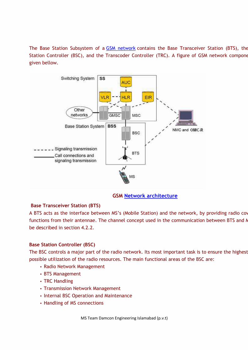
The Base Station Subsystem of a GSM network contains the Base Transceiver Station (BTS), the Base
Station Controller (BSC), and the Transcoder Controller (TRC). A figure of GSM network components is
given bellow.
GSM Network architecture
Base Transceiver Station (BTS)
A BTS acts as the interface between MS’s (Mobile Station) and the network, by providing radio coverage
functions from their antennae. The channel concept used in the communication between BTS and MS will
be described in section 4.2.2.
Base Station Controller (BSC)
The BSC controls a major part of the radio network. Its most important task is to ensure the highest
possible utilization of the radio resources. The main functional areas of the BSC are:
• Radio Network Management
• BTS Management
• TRC Handling
• Transmission Network Management
• Internal BSC Operation and Maintenance
• Handling of MS connections
MS Team Damcon Engineering Islamabad (p.v.t)
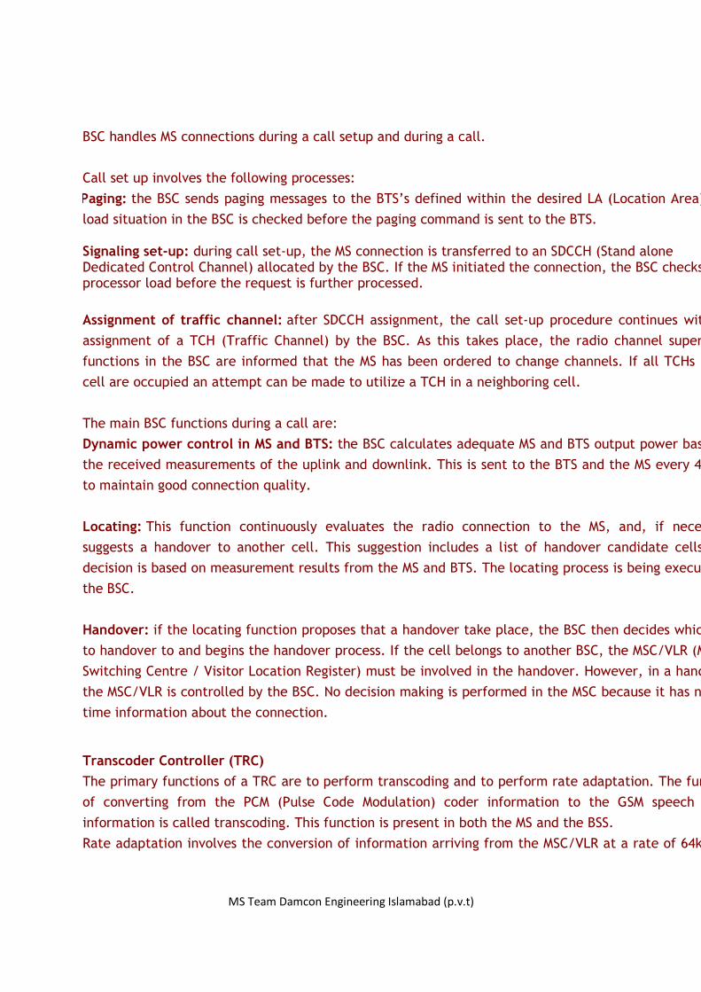
BSC handles MS connections during a call setup and during a call.
Call set up involves the following processes:
Paging: the BSC sends paging messages to the BTS’s defined within the desired LA (Location Area). The
load situation in the BSC is checked before the paging command is sent to the BTS.
Signaling set-up: during call set-up, the MS connection is transferred to an SDCCH (Stand alone Dedicated Control Channel) allocated by the BSC. If the MS initiated the connection, the BSC checks its processor load before the request is further processed.
Assignment of traffic channel: after SDCCH assignment, the call set-up procedure continues with the
assignment of a TCH (Traffic Channel) by the BSC. As this takes place, the radio channel supervision
functions in the BSC are informed that the MS has been ordered to change channels. If all TCHs in the
cell are occupied an attempt can be made to utilize a TCH in a neighboring cell.
The main BSC functions during a call are:
Dynamic power control in MS and BTS: the BSC calculates adequate MS and BTS output power based on
the received measurements of the uplink and downlink. This is sent to the BTS and the MS every 480 ms
to maintain good connection quality.
Locating: This function continuously evaluates the radio connection to the MS, and, if necessary,
suggests a handover to another cell. This suggestion includes a list of handover candidate cells. The
decision is based on measurement results from the MS and BTS. The locating process is being executed in
the BSC.
Handover: if the locating function proposes that a handover take place, the BSC then decides which cell
to handover to and begins the handover process. If the cell belongs to another BSC, the MSC/VLR (Mobile
Switching Centre / Visitor Location Register) must be involved in the handover. However, in a handover,
the MSC/VLR is controlled by the BSC. No decision making is performed in the MSC because it has no real
time information about the connection.
Transcoder Controller (TRC)
The primary functions of a TRC are to perform transcoding and to perform rate adaptation. The function
of converting from the PCM (Pulse Code Modulation) coder information to the GSM speech coder
information is called transcoding. This function is present in both the MS and the BSS.
Rate adaptation involves the conversion of information arriving from the MSC/VLR at a rate of 64kbits/s

MS Team Damcon Engineering Islamabad (p.v.t)
to a rate of 16kbits/s, or transmission to a BSC (for a full rate call). This 16kbits/s contains 13kbits/s of
traffic and 3kbits/s of inband signaling information.
This is an important function. Without rate adaptation the links to BSC’ would require four times the
data rate capabilities. Such transmission capabilities form an expensive part of the network. By reducing
the rate to 16kbits/s, it is possible to use one quarter of the transmission links and equipment.
In Ericsson’s GSM systems, the TRC contains units, which perform transcoding and rate adaptation. These
hardware units are called Transcoder and Rate Adaptation Units (TRAUs). All TRAUs are pooled, meaning
that any BSC connected to the TRC can request the use of one of the TRAUs for a particular call.
The TRC also supports discontinuous transmission. If pauses in speech are detected, comfort noise is
generated by the TRAU in the direction of the MSC/VLR.
Data rates for a single call on GSM links
OMC-R (Operations & Maintenance Center-Radio)
OMC-R is the interface between the BSS and the human working in the system. The operations and
maintenance center (OMC) is connected to all equipment in the switching system and to the BSC. OMC
is that connected to the BSC. Thus the operations and maintenance needs of the Network Operations
division is provided by the OMC-R, while the OMC-S connected to the switching system is used for
controlling the switch operations. The OMC is the functional entity from which the network operator
monitors and controls the system. The purpose of OMC is to offer the user cost-effective support for
centralized, regional and local operational and maintenance activities that are required for a GSM
network. An important function of OMC-R is to provide a network overview and support the maintenance
activities of different operation and maintenance organizations.
THE NETWORK AND SWITCHING SUBSYSTEM(NSS)

MS Team Damcon Engineering Islamabad (p.v.t)
The GSM network and protocols
Mobile Services Switching Center (MSC)
The primary node in a GSM network is the MSC. It is the node, which
controls calls both to MS’s and from MS’s. The primary functions of an MSC
include the following:
Switching and call routing MSC interact with other nodes to successfully establish a call. During a call it
involves in handovers from one BSC to another and inter MSC handover. Charging MSC contains functions for charging mobile calls and information about the
particular charge rates to apply to a call at any given time or for a given
destination. During a call it records this information (Call Data Record-CDR)
and sends it to the billing center. Service provisioning Supplementary services are provided and managed by a MSC. In addition,
the SMS service is handled by MSC’s
MS Team Damcon Engineering Islamabad (p.v.t)
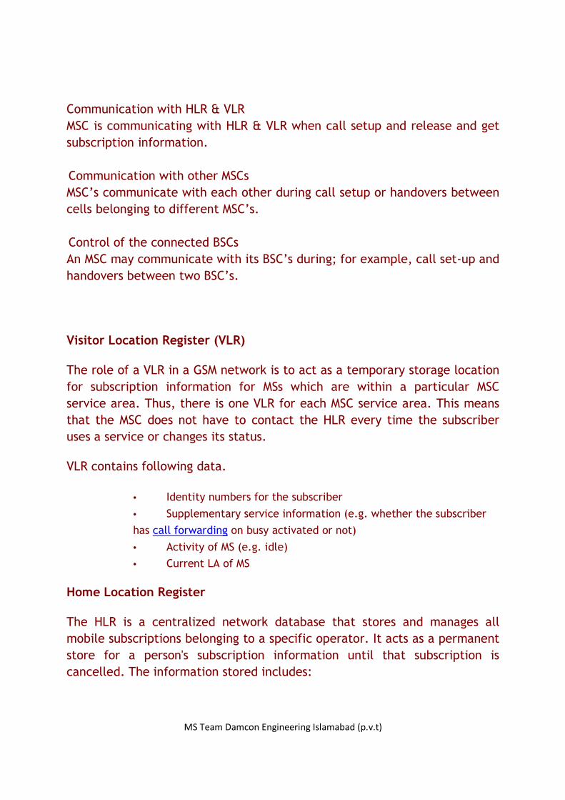
Communication with HLR & VLR MSC is communicating with HLR & VLR when call setup and release and get
subscription information. Communication with other MSCs MSC’s communicate with each other during call setup or handovers between
cells belonging to different MSC’s. Control of the connected BSCs An MSC may communicate with its BSC’s during; for example, call set-up and
handovers between two BSC’s.
Visitor Location Register (VLR)
The role of a VLR in a GSM network is to act as a temporary storage location
for subscription information for MSs which are within a particular MSC
service area. Thus, there is one VLR for each MSC service area. This means
that the MSC does not have to contact the HLR every time the subscriber
uses a service or changes its status.
VLR contains following data.
• Identity numbers for the subscriber
• Supplementary service information (e.g. whether the subscriber
has call forwarding on busy activated or not)
• Activity of MS (e.g. idle)
• Current LA of MS
Home Location Register
The HLR is a centralized network database that stores and manages all
mobile subscriptions belonging to a specific operator. It acts as a permanent
store for a person's subscription information until that subscription is
cancelled. The information stored includes:

MS Team Damcon Engineering Islamabad (p.v.t)
• Subscriber identity (i.e. IMSI, MSISDN)
• Subscriber supplementary services
• Subscriber location information (i.e. MSC service area)
• Subscriber authentication information
Authentication Center (AUC)
The primary function of an AUC is to provide information, which is then used
by an MSC/VLR to perform subscriber authentication and to, establish
ciphering procedures on the radio link between the network and MS’s. The
information provided is called a triplet and consists of:
• A non predictable Random number (RAND)
• A Signed Response (SRES)
• A ciphering Key (Kc)
Equipment Identity Register
The equipment identification procedure uses the identity of the equipment itself (IMEI) to ensure that the MS terminal equipment is valid.
GSM CELLS
There are two main types of cells:
Omni directional cell
An omni-directional cell (or omnicell) is served by a BTS with an antenna
which transmits equally in all directions (360 degrees).
Sector cell
A sector cell is the area of coverage from an antenna, which transmits, in
a given direction only. For example, this may be equal to 120 degrees or
180 degrees of an equivalent omni- directional cell. One BTS can serve one

MS Team Damcon Engineering Islamabad (p.v.t)
of these sector cells with a collection of BTS’s at a site serving more than
one, leading to terms such as two-sectored sites and more commonly,
three-sectored sites.
Typically, omni-directional cells are used to gain coverage, whereas sector cells are used to gain capacity.
Cell types
Reuse of frequency is an important factor when planning a GSM network. The frequency re-use patterns recommended for GSM are the 4/12 and the 3/9 pattern. 4/12 means that there are four three-sector sites supporting twelve cells using twelve frequency groups.
Frequency reuse patterns

MS Team Damcon Engineering Islamabad (p.v.t)
FREQUENCY HOPPING
Multi wave propagation varies the signal strength which causes fading dips.
This is known as Rayleigh fading which is frequency dependent. Frequency
Hopping changes the frequency with time to eliminate frequency dependent
Rayleigh fading. Frequency Hopping reduces the effects of interferences and
gives a great support to cater the capacity upgrading as well.
There are 2 types of frequency hopping, Base Band Hopping (BBH) and
Synthesized Frequency Hopping (SFH)
Base Band Hopping (BBH)
Base band hopping
In this type of hopping, only frequencies used by the TRXs can be allocated
to the FHS (Frequency Hopping Sequence).The BCCH supporting Time Slot
cannot hop. TS 0 of the BCCH TRX is always transmitting on the BCCH
frequency. Other timeslots can use other frequencies unless the BCCH
frequency is transmitted by any other TRX at the same time.
The major advantage of the BBH is the time TS 1 to TS 7 of the BCCH
frequency containing TRX is allowed to perform hopping. But Frequency
Hopping performs best with at least 4 hopping frequencies. So cells need at
least 4 TRXs and it is the disadvantage of this system.
Synthesized Frequency Hopping (SFH)

MS Team Damcon Engineering Islamabad (p.v.t)
Synthesized Frequency Hopping
In SFH each frame unit is connected to one carrier unit. Hopping is
performed by changing the carrier unit by changing a synthesizer. As the
communication is not hopping between the carrier units but the carrier unit
frequency itself is hopping. So many frequencies can be used as hopping
frequencies. In SFH, TRX returns in every time slot to a different frequency.
Thus the TCH remains on the same TRX but the frequencies of that TCH
hops.
FREQUENCY PLANNING PARAMETERS
BCCH – Broadcast Control Channel
BCCH frequency planning is done for each sector in the site individually.
The BCCH frequency must be determined so that the same frequency of
some other site does not interfere with the planning site (Co-channel
interference) and the adjacent higher frequency and the lower frequency
also should not be used in a near site that can be in a position to interfere
the given site (Adjacent channel interference).
HSN – Hopping Sequence Number
It is one of 4 input parameters to the GSM hopping sequence generator
algorithm.Range of HSN is 0 to 63. HSN = 0 means the hopping is in cyclic
mode.
MAIO - Mobile Allocated Index Offset

MS Team Damcon Engineering Islamabad (p.v.t)
The Mobile Allocated Index allows determining the correct line in the
Mobile Allocation look up table to find the corresponding ARFCN .The MAIO
is selectable for each timeslot and each TRX separately. It is constant on
the TRX but it changes between the frame units.
BSIC – Base Station Identification Code
BSIC Channels are to identify each station and sub stations. It can be
represented in 2 codes.
NCC (Network Color Code) – Is represented in 3 bit binary form.
Therefore it the numbers are from 0 to 7.
BCC (Base station Color Code) – It’s also in 3 bit form. Can be used 0 to
7.
CHANNEL CONCEPT
Each timeslot on a TDMA (Time Division Multiple Access) frame is called a physical
channel. Therefore, there are 8 physical channels per carrier frequency in GSM.
Physical channels can be used to transmit speech, data or signaling information. A
physical channel may carry different messages, depending on the information that is
to be sent. These messages are called logical channels. Information is transmitted via
physical channels as the form of bursts. The relationship between bursts and logical
channels is shown in the figure below.

MS Team Damcon Engineering Islamabad (p.v.t)
The relationship between bursts and logical channels
The Control channels are control the communication (signaling) of the mobile station
with the base transceiver station while the Traffic channels bares the voice
information. Logical channels are transmitted on physical channels. The method of
placing logical channels on physical channels is called mapping. While most logical
channels take only one time slot to transmit, some take more. If so, the logical
channel information is carried in the same physical channel time slot on consecutive
TDMA frames. Because logical channels are short, several logical channels can share
the same physical channel, making the use of time slots more efficient.
Most of the cells are having 4 simultaneous carriers (or TRXs). The figure below shows
the carrier frequencies for a sample cell, including an additional allocation of a time
slot for DCCH (Dedicated Control Channel) in TRX1 due to a high call set-up load in
the cell. Otherwise one DCCH is enough.

MS Team Damcon Engineering Islamabad (p.v.t)
The relationship between physical channels and logical channels
Time slot 0 of the first carrier frequency in a cell is always reserved for
signaling purposes. In this way, when an MS is determining whether a carrier
frequency is a BCCH (Broadcast Control Channel) carrier, it knows where to look.
8 SDCCH's and 4 SACCH's all can share the same physical channel (Channel D in the
figure above). This means that 8 calls can be set-up simultaneously on one physical
channel.
All time slots in a cell other than those assigned for signaling information are used for
traffic, i.e. speech or data. Logical channel TCH is used. In addition, at regular
intervals during a call, an MS transmits to the BTS measurements it has made about
signal strength and quality. Logical channel SACCH is used for this, replacing one TCH
time slot at a time.
AUTHENTICATION PROCESS OF A SUBSCRIBER
MS Team Damcon Engineering Islamabad (p.v.t)
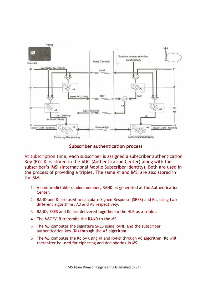
Subscriber authentication process
At subscription time, each subscriber is assigned a subscriber authentication Key (Ki). Ki is stored in the AUC (Authentication Center) along with the subscriber’s IMSI (International Mobile Subscriber Identity). Both are used in the process of providing a triplet. The same Ki and IMSI are also stored in the SIM.
1. A non-predictable random number, RAND, is generated at the Authentication Center.
2. RAND and Ki are used to calculate Signed Response (SRES) and Kc, using two different algorithms, A3 and A8 respectively.
3. RAND, SRES and Kc are delivered together to the HLR as a triplet.
4. The MSC/VLR transmits the RAND to the MS.
5. The MS computes the signature SRES using RAND and the subscriber authentication key (Ki) through the A3 algorithm.
6. The MS computes the Kc by using Ki and RAND through A8 algorithm. Kc will thereafter be used for ciphering and deciphering in MS.

MS Team Damcon Engineering Islamabad (p.v.t)
7. The signature SRES is sent back to MSC/VLR, which performs authentication, by checking whether, the SRES from the MS and the SRES from the AUC match. If so, the subscriber is permitted to use the network. If not, the subscriber is barred from network access.
GSM NETWORK IDENTITIES
Network identities are numbers that a GSM network uses to locate a mobile
subscriber when it is establishing a call to that subscriber. As the network
relies on these identities to route calls to subscribers, it is important that
each identity is unique and correct.
Mobile Station ISDN number (MSISDN)
The Mobile Station ISDN number (MSISDN) uniquely identifies a mobile
telephone subscription in the PSTN numbering plan. This is the number
dialed when calling a mobile subscriber.
MSISDN
CC Country Code NDC National Destination Code SN Subscriber Number International Mobile Subscriber Identity (IMSI)
The International Mobile Subscriber Identity (IMSI) is a unique identity
allocated to each subscriber that facilitates correct subscriber
MS Team Damcon Engineering Islamabad (p.v.t)
identification over the radio path and through the network. It is used for
all signaling in the PLMN.
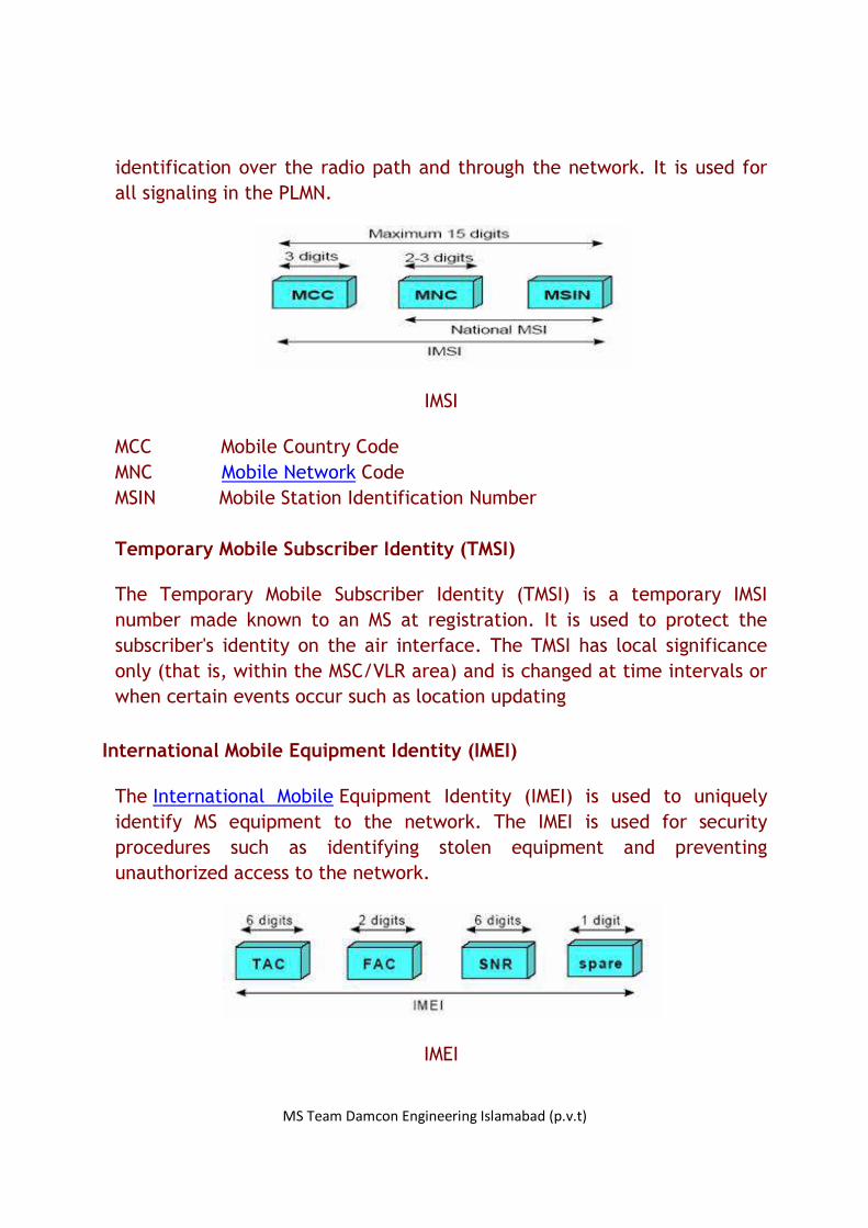
IMSI
MCC Mobile Country Code MNC Mobile Network Code MSIN Mobile Station Identification Number Temporary Mobile Subscriber Identity (TMSI)
The Temporary Mobile Subscriber Identity (TMSI) is a temporary IMSI
number made known to an MS at registration. It is used to protect the
subscriber's identity on the air interface. The TMSI has local significance
only (that is, within the MSC/VLR area) and is changed at time intervals or
when certain events occur such as location updating
International Mobile Equipment Identity (IMEI)
The International Mobile Equipment Identity (IMEI) is used to uniquely
identify MS equipment to the network. The IMEI is used for security
procedures such as identifying stolen equipment and preventing
unauthorized access to the network.
IMEI
MS Team Damcon Engineering Islamabad (p.v.t)
TAC Type Approval Code, determined by a central GSM body FAC Final Assembly Code, identifies the manufacturer
SNR Serial Number, an individual serial number of six digits
uniquely identifies all equipment within each TAC and FAC spare A spare digit for future use. When transmitted by the MS this
digit should always be zero Mobile Station Roaming Number (MSRN)
The Mobile Station Roaming Number (MSRN) is a temporary network
identity which is assigned during the establishment of a call to a roaming
subscriber.
Location Area Identity (LAI)
The Location Area Identity (LAI) is a temporary network identity, which is
also required for routing. The two main purposes of the LAI are, paging,
which is used to inform the MSC of the LA in which the MS is currently
situated and location updating of mobile subscribers.
Cell Global Identity (CGI)
The Cell Global Identity (CGI) is used for identifying individual cells within
a LA. Cell identification is achieved by adding a Cell Identity (CI) to the LAI
components.
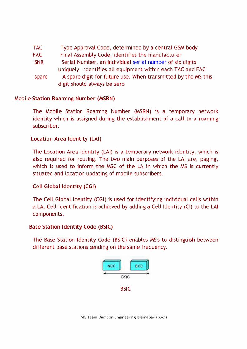
Base Station Identity Code (BSIC)
The Base Station Identity Code (BSIC) enables MS's to distinguish between
different base stations sending on the same frequency.
BSIC
MS Team Damcon Engineering Islamabad (p.v.t)
NCC Network Color Code (3 bits) identifies the PLMN. It does not
uniquely identify the operator. NCC is primarily used to
distinguish between operators on each side of a border
BCC Base Station Color Code (3 bits) identifies the Base Station to
help distinguish between BTS using the same control frequencies
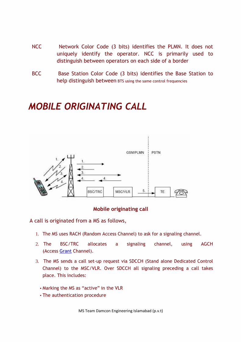
MOBILE ORIGINATING CALL
Mobile originating call
A call is originated from a MS as follows,
1. The MS uses RACH (Random Access Channel) to ask for a signaling channel.
2. The BSC/TRC allocates a signaling channel, using AGCH
(Access Grant Channel).
3. The MS sends a call set-up request via SDCCH (Stand alone Dedicated Control
Channel) to the MSC/VLR. Over SDCCH all signaling preceding a call takes
place. This includes:
• Marking the MS as “active” in the VLR
• The authentication procedure

MS Team Damcon Engineering Islamabad (p.v.t)
• Start ciphering
• Equipment identification
• Sending the B-subscriber’s number to the network
• Checking if the subscriber has the service “Barring of outgoing calls” activated
4. The MSC/VLR instructs the BSC/TRC to allocate an idle TCH. The BTS and MS are told to tune to the TCH.
5. The MSC/VLR forwards the B–number to an exchange in the PSTN, which establishes a connection to the subscriber.
6. If the B-subscriber answers, the connection is established.
MICROWAVE LINK
MAIN COMPONENTS OF A MICROWAVE LINK
Components of a Microwave link
The radio equipment configuration of a microwave link consists of,
MS Team Damcon Engineering Islamabad (p.v.t)
• Indoor Unit (IDU) • Outdoor Unit (ODU) • Antenna Unit • ODU to IDU cabling (IF cable)
• Digital Distribution Frame (DDF)
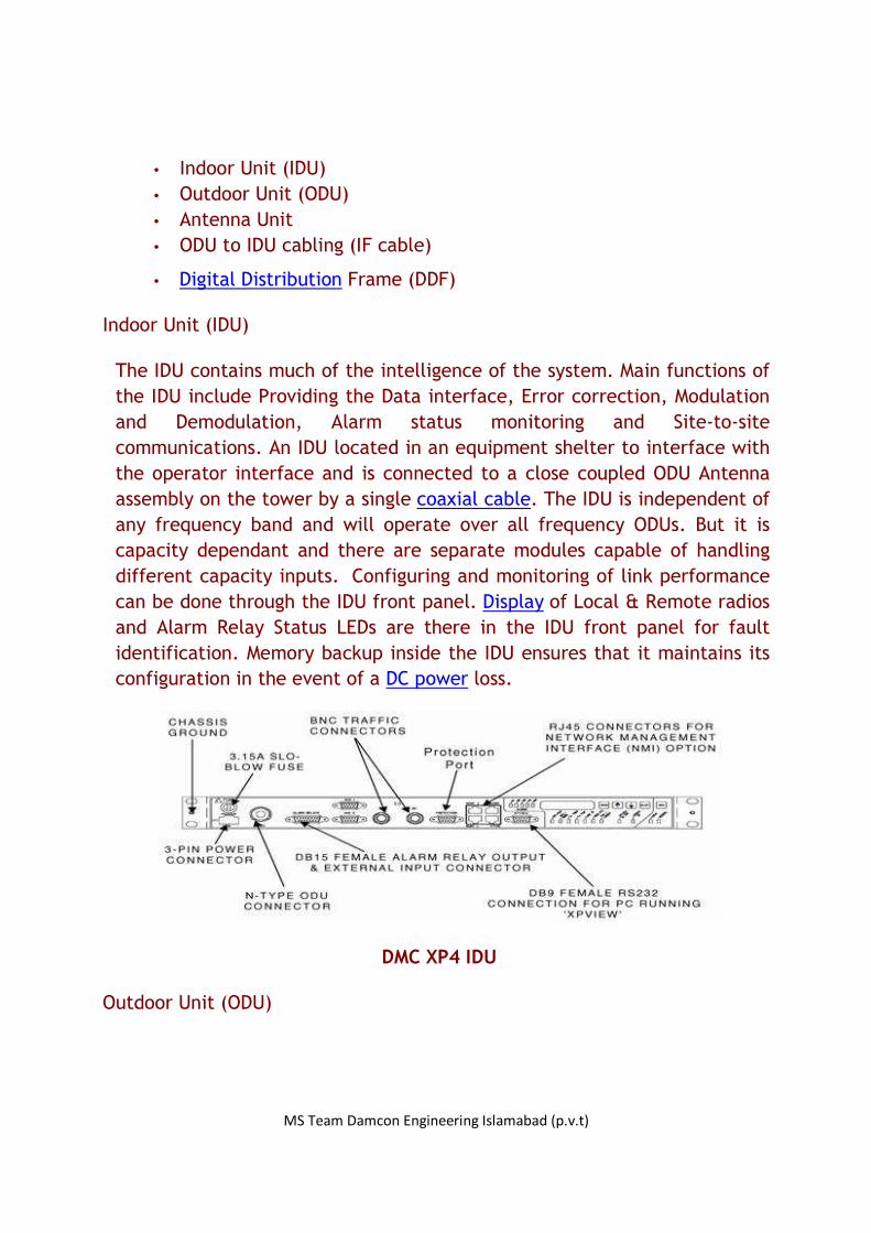
Indoor Unit (IDU)
The IDU contains much of the intelligence of the system. Main functions of
the IDU include Providing the Data interface, Error correction, Modulation
and Demodulation, Alarm status monitoring and Site-to-site
communications. An IDU located in an equipment shelter to interface with
the operator interface and is connected to a close coupled ODU Antenna
assembly on the tower by a single coaxial cable. The IDU is independent of
any frequency band and will operate over all frequency ODUs. But it is
capacity dependant and there are separate modules capable of handling
different capacity inputs. Configuring and monitoring of link performance
can be done through the IDU front panel. Display of Local & Remote radios
and Alarm Relay Status LEDs are there in the IDU front panel for fault
identification. Memory backup inside the IDU ensures that it maintains its
configuration in the event of a DC power loss.
DMC XP4 IDU
Outdoor Unit (ODU)

MS Team Damcon Engineering Islamabad (p.v.t)
The ODU converts data from the IDU into an RF signal for transmission. It
also converts the RF signal from the far end to suitable data to transmit to
the IDU. ODUs are weatherproofed units that are mounted on top of a
tower either directly connected to a microwave antenna or connected to it
through a wave guide. Here ODUs are full duplex configured. The ODU
receives its power from the IDU through acoaxial cable. ODU parameters
are configured and monitored through the IDU. Each ODU is designed to
operate over a predefined frequency band. For example 21.2 - 23.6GHz for
a 23GHz system, 17.7 - 19.7GHz for a 18GHz system and 24.5 - 26.5GHz for
a 26GHz system as for DMC XP4 ODUs. Suitable ground wire should be
connected to the ODU ground lug to an appropriate ground point on the
antenna mounting or tower for lightning protection. It should be noted
that this unit is electronically controlled. Transmitted power is controlled
by adjusting a value on the IDU which instructs the ODU to adjust the drive
voltage on its Tx PIN diode attenuator. The configuration of a DMC XP4
ODU is shown below.
DMC XP4 ODU
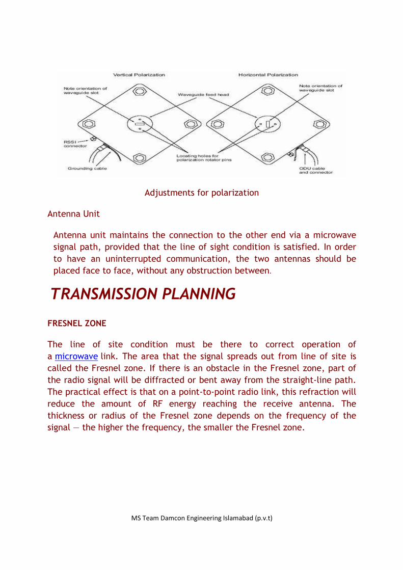
The polarization of the transmitted signal is determined by the position of
the polarization rotator fitted within the ODU mounting collar. The rotator
is an integral part of the antenna-mounting bracket. The default setting is
for vertical polarization. The ODU must be mounted on the collar to match
the chosen polarization.
MS Team Damcon Engineering Islamabad (p.v.t)
Adjustments for polarization
Antenna Unit
Antenna unit maintains the connection to the other end via a microwave
signal path, provided that the line of sight condition is satisfied. In order
to have an uninterrupted communication, the two antennas should be
placed face to face, without any obstruction between.
TRANSMISSION PLANNING
FRESNEL ZONE
The line of site condition must be there to correct operation of
a microwave link. The area that the signal spreads out from line of site is
called the Fresnel zone. If there is an obstacle in the Fresnel zone, part of
the radio signal will be diffracted or bent away from the straight-line path.
The practical effect is that on a point-to-point radio link, this refraction will
reduce the amount of RF energy reaching the receive antenna. The
thickness or radius of the Fresnel zone depends on the frequency of the
signal — the higher the frequency, the smaller the Fresnel zone.

MS Team Damcon Engineering Islamabad (p.v.t)
Microwave lin
The radius of the Fresnel zone can be calculated by the formula bellow.
Fn = The nth Fresnel Zone radius in meter
d1 = The distance of P from one end in meter
d2 = The distance of P from the other end in meter
λ = The wavelength of the transmitted signal in meter
The direct path between the transmitter and the receiver needs a clearance
above ground of at least 60% of the radius of the first Fresnel zone to
achieve free space propagation conditions.
FREE SPACE LOSS
As signals spread out from a radiating source, the energy is spread out over
a largersurface area. As this occurs, the strength of that signal gets weaker.
Free space loss (FSL), measured in dB specifies how much the signal has
weakened over a given distance.
FSL = 92.4 + 20 log10 D + 20 log10 F
FSL = Free Space Loss in dB
D = Path Length in kilometers

MS Team Damcon Engineering Islamabad (p.v.t)
F = Radio Frequency in Gigahertz
LINK BUDGET
Link budget is the itemized list of all system losses and gains in dB from the
transmitter on one end to the receiver at the other end.
Radio path link budget
FADING AND FADE MARGINS
Multipath Fading is the dominant fading mechanism for frequencies lower
than 10GHz. A reflected wave causes a multipath, i.e. when a reflected
wave reaches the receiver as the direct wave that travels in a straight line
from the transmitter. As a thumb rule, multipath fading, for radio links
having bandwidths less than 40MHz and path lengths less than 30Km is
described as flat instead of frequency selective.
Flat fading
A fade where all frequencies in the channel are equally affected called
Flat fading. There is barely noticeable variation of the amplitude of the
signal across the channel bandwidth.
Frequency-selective fading
MS Team Damcon Engineering Islamabad (p.v.t)
In Frequency-selective fading there are amplitude and group delay
distortions across the channel bandwidth.
Rain fading
Rain attenuates the signal caused by the scattering and absorption of
electromagnetic waves by rain drops and it is significant for long paths
(>10Km). Vertical polarization is far less susceptible to rainfall attenuation
than are horizontal polarization frequencies.
Fade margin
Fade margin is the difference (measured in dB) between the nominal signal
level received at one end of a radio link and the signal level required by
that radio to assure that a packet of data is decoded without error. In
other words, fade margin is the difference between the signal received
and the radio’s specified receiver’s sensitivity. (Figure 11.3)
Fade margin = Signal level received – Sensitivity of the receiver
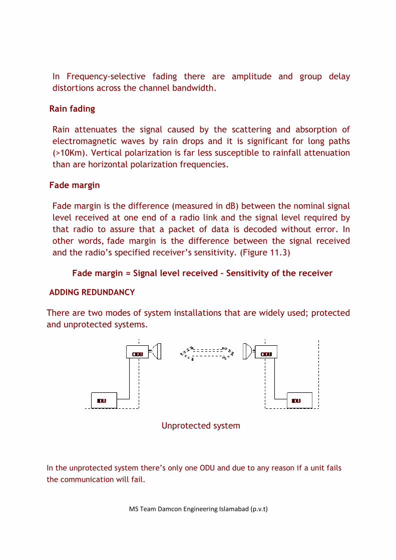
ADDING REDUNDANCY
There are two modes of system installations that are widely used; protected
and unprotected systems.
Unprotected system
In the unprotected system there’s only one ODU and due to any reason if a unit fails
the communication will fail.
MS Team Damcon Engineering Islamabad (p.v.t)
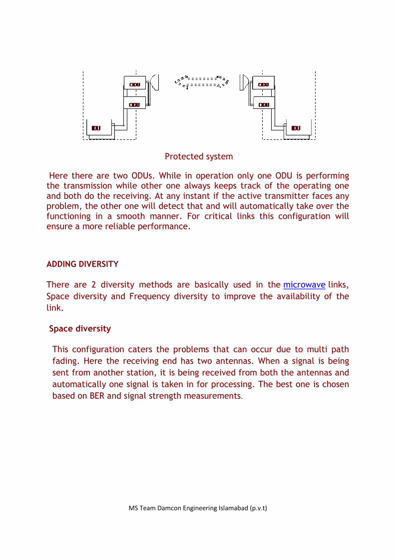
Protected system
Here there are two ODUs. While in operation only one ODU is performing the transmission while other one always keeps track of the operating one and both do the receiving. At any instant if the active transmitter faces any problem, the other one will detect that and will automatically take over the functioning in a smooth manner. For critical links this configuration will ensure a more reliable performance.
ADDING DIVERSITY
There are 2 diversity methods are basically used in the microwave links,
Space diversity and Frequency diversity to improve the availability of the
link.
Space diversity
This configuration caters the problems that can occur due to multi path
fading. Here the receiving end has two antennas. When a signal is being
sent from another station, it is being received from both the antennas and
automatically one signal is taken in for processing. The best one is chosen
based on BER and signal strength measurements.
MS Team Damcon Engineering Islamabad (p.v.t)
System with space diversity
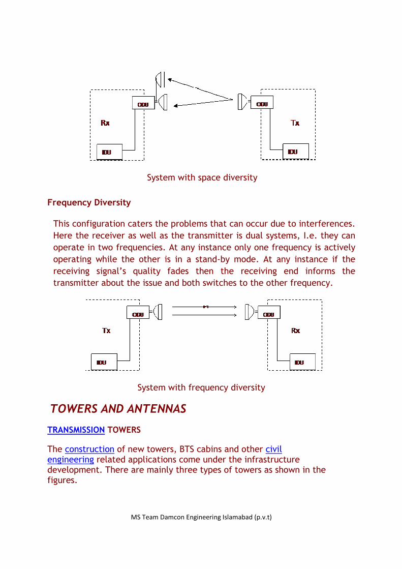
Frequency Diversity
This configuration caters the problems that can occur due to interferences.
Here the receiver as well as the transmitter is dual systems, I.e. they can
operate in two frequencies. At any instance only one frequency is actively
operating while the other is in a stand-by mode. At any instance if the
receiving signal’s quality fades then the receiving end informs the
transmitter about the issue and both switches to the other frequency.
System with frequency diversity
TOWERS AND ANTENNAS
TRANSMISSION TOWERS
The construction of new towers, BTS cabins and other civil engineering related applications come under the infrastructure development. There are mainly three types of towers as shown in the figures.

MS Team Damcon Engineering Islamabad (p.v.t)
Monopole Self Support Guyed
Monopoles consist of tapered steel tubes that fit over each other to form astable pole
Self-supporting towers are having free-standing lattice structures
Guyed towers are stabilized by tethered wires
ANTENNAS
There are several types of antennas are being used to meet the requirement of the network. General BTS location includes GSM (900MHz band) antennas and DCS (1800MHz band) antennas to provide the GSM coverage. Sometimes dual band antennas that are having both GSM and DCS facility are used rather than having 2 separate antennas. In addition to that some Sites have 3G antennas and WiMax antennas.
Antenna tilting is used to adjust the coverage area of an antenna. There are two ways of antenna tilt adjustment mechanisms.
Mechanical tilt

MS Team Damcon Engineering Islamabad (p.v.t)
Tilting the antenna using an adjustable joint that is fixing the antenna to the tower is mechanical tilting. (Figure A)
Electrical tilt
There is a screw at the bottom of the antenna. This screw is connected to a ferrous core, which is in inside of the antenna. When the screw is rotated the down tilt of the main lobe is changed. (Figure B)
Figure A: Mechanical tilt Figure B: Electrical tilt
VSWR MEASUREMENT
VSWR stands for Voltage Standing Wave Ratio. An impedance of exactly 50 Ohm can only be practically achieved at one frequency. The VSWR defines how far the impedance differs from 50 Ohm with a wide-band antenna. The power delivered from the transmitter can no longer be radiated without loss because of this incorrect compensation. Part of this power is reflected at the antenna and is returned to the transmitter. The forward and return power forms a standing wave with corresponding maximum and minimum voltages. This wave ratio defines the level of compensation of the antenna.
This test is performed to make sure the cables from BTS to antenna are installed properly. Readings are taken of the whole system of antenna, jumpers and cable up to the BTS. Analyzer is used to measure the VSWR and it draws a graph taking frequency to x-axis and VSWR to y-axis.
Calibration

MS Team Damcon Engineering Islamabad (p.v.t)
Before any reading is taken, the very first thing is to calibrate the analyzer. Analyzer is switched on and cable is connected to the port. The desired frequency range is entered (890MHz – 960MHz for GSM and 1710MHz – 1880MHz for DCS). To the other end of the port, the ‘Open’ side of the dummy is connected and reading is taken. Then ‘Close’ side and ‘Load’ side of the dummy should be connected. The analyzer process data and if it gives a VSWR reading around 1 for the ‘Load’, then it is ready to take the readings.
Taking Measurements
Jumper cable to the BTS is removed from the BTS port and connected to the analyzer and a graph is obtained. The connectors should be well-tighten; otherwise a false reading may be given. The VSWR graph should be below 1.2 for an acceptable installation. If not, the next check points going in sequence are,
• Connection point of jumper and antenna cable. • Replace the antenna by the dummy load at the next end
jumper. • Replace the jumper cable and measure. • Worst case, replace the antenna cable.
Following are two graphs obtained from a VSWR test. The graph at top is one with the VSWR at an acceptable range and the bottom one is one which is not.

MS Team Damcon Engineering Islamabad (p.v.t)
VSWR is at an acceptable range
VSWR is not at an acceptable range

MS Team Damcon Engineering Islamabad (p.v.t)
INDOOR SOLUTIONS
When providing an indoor coverage, it is necessary to be aware of coverage
and interference. (i.e. signals from indoor cell must be strong enough to
guarantee a full coverage of the building and get free of interference from
the outdoor cells.) So the signals from indoor cell must be limited not to
interference with the outside network.
Before installing an indoor cell, it must be design a plan with antenna
locations, cable lengths, Splitter types, Tappers…etc by using the map of
the building and special software (e.g. RF UV). After finishing performance
tests, indoor site installations can be done. There are two types of indoor
antennas for the indoor solution process: Omni & panel.
Indoor antennas
By using Omni antennas, signal can be transmitted over an area of
hemisphere. So it is very useful for covering an open area (like a room, hall
or an auditorium). It is possible to give coverage for a long directional area
(i.e. corridor, stairs…etc) by using Directional antennas.
POWER SYSTEM OF A TYPICAL BTS SITE
The following figure shows the Power System of a typical BTS site.

MS Team Damcon Engineering Islamabad (p.v.t)
Power System of a typical BTS site
A typical BTS site has a 2 way power supply, CEB and Generator power. The
ATS (Automatic Transfer switch) is there to select the power source. The
rectifier converts the AC supply voltage to a DC voltage of -48V. The battery
bank is there to supply the power during an emergency case that is when
both the CEB and Generator power fails. The HRC (High Rupture Capacity
Fuses) prevents the equipment from voltage spikes.
The BTS and modems operate in -48V DC. The rectifier unit converts the AC
supply into -48V DC. Battery bank is used as a back-up power at a mains
failure. The manufactures provide battery cells, the rack and other
necessary components for every battery bank.
UNINTERRUPTIBLE POWER SUPPLY (UPS)
An uninterruptible power supply (UPS), also known as a continuous power
supply (CPS) or a battery backup, is a device which maintains a continuous

MS Team Damcon Engineering Islamabad (p.v.t)
supply of electric power to connected equipment by supplying power from a
separate source when utility power is not available. It differs from an
auxiliary power supply or standby generator, which does not provide instant
protection from a momentary power interruption, however could be used to
provide uninterrupted power to equipment for 1 - 20 minutes until a
generator can be turned on. The switch over time is stated by most
manufacturers as being less than 4 milliseconds, but typically can be as long
as 25 milliseconds depending on the amount of time it takes the Standby
UPS to detect the lost utility voltage. There are 2 types of UPS available.
Off-line UPS
This type of UPS remains idle until a power failure occurs, and then
switches from utility power to its own power source, almost
instantaneously.
Off-line UPS
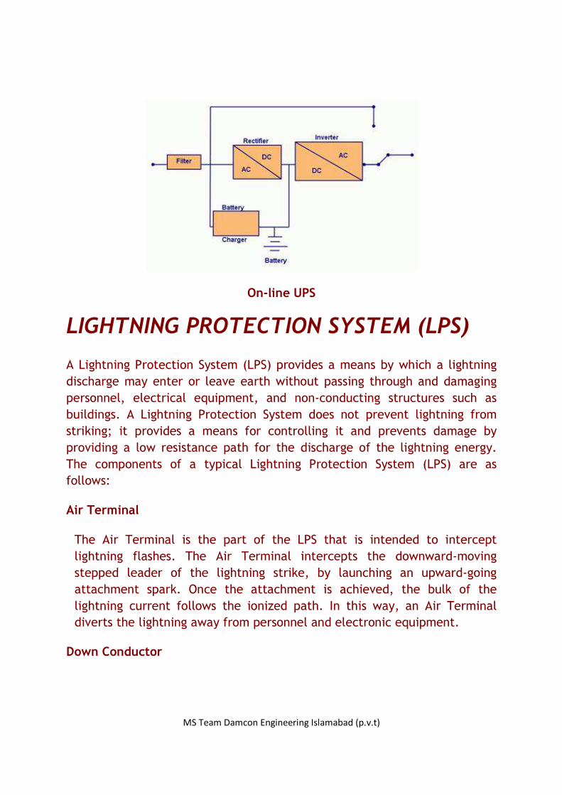
On-line UPS
On-line UPS continuously powers the protected load from its energy
reserves stored in a lead-acid battery or flywheel, while simultaneously
replenishing the reserves from the AC power. It also provides protection
against all common power problems, and for this reason it is also known as
a power conditioner and a line conditioner.
MS Team Damcon Engineering Islamabad (p.v.t)
On-line UPS
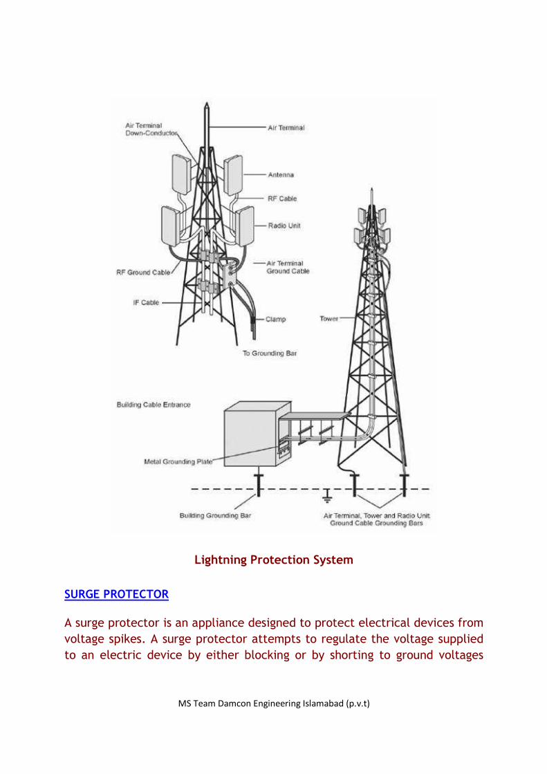
LIGHTNING PROTECTION SYSTEM (LPS)
A Lightning Protection System (LPS) provides a means by which a lightning
discharge may enter or leave earth without passing through and damaging
personnel, electrical equipment, and non-conducting structures such as
buildings. A Lightning Protection System does not prevent lightning from
striking; it provides a means for controlling it and prevents damage by
providing a low resistance path for the discharge of the lightning energy.
The components of a typical Lightning Protection System (LPS) are as
follows:
Air Terminal
The Air Terminal is the part of the LPS that is intended to intercept
lightning flashes. The Air Terminal intercepts the downward-moving
stepped leader of the lightning strike, by launching an upward-going
attachment spark. Once the attachment is achieved, the bulk of the
lightning current follows the ionized path. In this way, an Air Terminal
diverts the lightning away from personnel and electronic equipment.
Down Conductor

MS Team Damcon Engineering Islamabad (p.v.t)
The Down-Conductor is that part of the external Lightning Protection
System (LPS) that conducts lightning current from the Air Terminal system
to the Earth Termination system.
Outdoor Units Grounding
The Outdoor Unit, consisting of a Radio Frequency Unit and Antenna, must
include a grounding point for connection to the grounding.
Earth Termination System
The Earth Termination System is that part of external LPS that is intended
to conduct and disperse lightning current to earth.
Lightning Protectors
Lightning Protectors provide an additional protection to the equipment
embedded protectors, in places where lightning occurs with a high
probability.
MS Team Damcon Engineering Islamabad (p.v.t)
Lightning Protection System
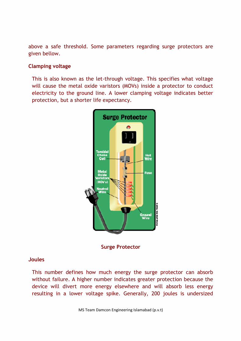
SURGE PROTECTOR
A surge protector is an appliance designed to protect electrical devices from
voltage spikes. A surge protector attempts to regulate the voltage supplied
to an electric device by either blocking or by shorting to ground voltages
MS Team Damcon Engineering Islamabad (p.v.t)
above a safe threshold. Some parameters regarding surge protectors are
given bellow.
Clamping voltage
This is also known as the let-through voltage. This specifies what voltage
will cause the metal oxide varistors (MOVs) inside a protector to conduct
electricity to the ground line. A lower clamping voltage indicates better
protection, but a shorter life expectancy.
Surge Protector
Joules
This number defines how much energy the surge protector can absorb
without failure. A higher number indicates greater protection because the
device will divert more energy elsewhere and will absorb less energy
resulting in a lower voltage spike. Generally, 200 joules is undersized
MS Team Damcon Engineering Islamabad (p.v.t)
protection since harmful voltage spikes are significantly larger than 200
joules. Better protectors start at 1000 joules and 50,000 amperes. If
properly installed, for every joule absorbed by a protector, another 4 or 30
joules may be dissipated harmlessly into ground.
Response time
Surge protectors do not kick in immediately; a slight delay exists. The
longer the response time the longer the connected equipment will be
exposed to the surge. However, surges don't happen immediately either.
Surges usually take around a few microseconds to reach their peak voltage
and a surge protector with a nanosecond response time would kick in fast
enough to suppress the most damaging portion of the spike.
WCDMA TECHNOLOGY
By definition, the bandwidth of a WCDMA (Wideband Code Division Multiple
Access) system is 5 MHz or more, and this 5 MHz is also the nominal
bandwidth of all 3G WCDMA proposals.
This bandwidth was chosen because,
• It is enough to provide data rates of 144 and 384 Kbps (these
were 3G targets), and even 2 Mbps in good conditions.
• Bandwidth is always scarce, and the smallest possible allocation
should be used, especially if the system must use frequency bands
already occupied by existing 2G systems.
• This bandwidth can resolve more multipaths than narrower
bandwidths, thus improving performance.
MS Team Damcon Engineering Islamabad (p.v.t)
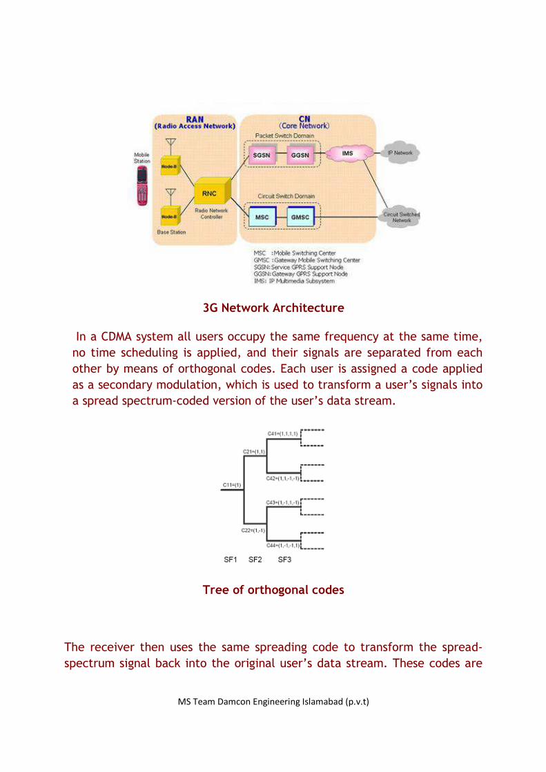
3G Network Architecture
In a CDMA system all users occupy the same frequency at the same time,
no time scheduling is applied, and their signals are separated from each
other by means of orthogonal codes. Each user is assigned a code applied
as a secondary modulation, which is used to transform a user’s signals into
a spread spectrum-coded version of the user’s data stream.
Tree of orthogonal codes
The receiver then uses the same spreading code to transform the spread-
spectrum signal back into the original user’s data stream. These codes are

MS Team Damcon Engineering Islamabad (p.v.t)
chosen so that they have low cross-correlation with other codes. This means
that correlating the received spread-spectrum signal with the assigned code
despreads only the signal that was spread using the same code. All other
signals remain spread over a large bandwidth. That is, only the receiver
knowing the right spreading code can extract the original signal from the
received spread-spectrum signal. The figure above shows the tree of
orthogonal codes.
Power Control in WCDMA
Power control in uplink must make signal powers from different users
nearly equal in order to maximize the total capacity in the cell.
In downlink the power control must keep the signal at minimal required
level in order to decrease the interference to users in other cells.
Received power at the base station
PDH and SDH
PLESIOCHRONOUS DIGITAL HIERARCHY (PDH)
There are two types of multiplexing hierarchies of Time Division Multiplexing
(TDM), used in digital transmission. Traditionally,
digital transmission systems and hierarchies have been based on
multiplexing signals which are plesiochronous. To recover a 64kbps channel

MS Team Damcon Engineering Islamabad (p.v.t)
from a 140Mbps PDH signal it is necessary to demultiplex the signal all the
way down to the 2 Mbps E1 level before the location of the 64 kbps channel
can be identified. PDH requires multiplexing steps of 2-8, 8-34, 34-140 to
add or demultiplexing steps of 140-34, 34-8, 8-2 to drop out an individual
speech or data channel.
Plesiochronous Digital Hierarchy
Signal Digital bit rate / (kb/s) Channels
E0 64 1 E0
E1 2048 32 E0
E2 8448 4 E1
E3 34368 16 E1
E4 139264 64 E1
SYNCHRONOUS DIGITAL HIERARCHY (SDH)
Synchronous Digital Hierarchy is a standard for telecommunications
transport formulated by the International Telecommunication Union (ITU).
The basic format of an SDH signal allows it to carry many different services
in its Virtual Container (VC) because it is bandwidth-flexible. This capability
allows for such things as thetransmission of high speed packet switched
services, ATM. However SDH still permits transport and networking at the
2Mbps, 34Mbps, and 140Mbps levels accommodating the existing PDH signals.
In addition SDH supports the transport of signals based on the 1.544Mbps
hierarchy used in America.
Synchronous Digital Hierarchy
Bit rate / (Mb/s) Abbreviated SDH SDH Capacity
51.84 51 Mb/s STM-0 21 E1
155.52 155 Mb/s STM-1 63 E1
622.08 622 Mb/s STM-4 4 E4
2488.32 2.4 Gb/s STM-16 16 E4

MS Team Damcon Engineering Islamabad (p.v.t)
9953.28 10 Gb/s STM-64 64 E4
39813.12 40 Gb/s STM-256 256 E4
SIGNALING SYSTEM NO.7 (SS7)
Signaling System No. 7 (SS7 or C7) is a global standard for
telecommunication defined by the International Telecommunication Union
(ITU) Telecommunication Standardization Sector (ITU-T). The standard
defines the procedures and protocol by which network elements in the
public switched telephone network (PSTN) exchange information over a
digital signaling network to effect wireless (cellular) and wire line call
setup, routing and control.
Each signaling point in the SS7 network is uniquely identified by a numeric
point code. Point codes are carried in signaling messages exchanged
between signaling points to identify the source and destination of each
message. Each signaling point uses a routing table to select the appropriate
signaling path for each message. There are three kinds of signaling points in
the SS7 network.
SSP (Service Switching Point)
SSPs are switches that originate, terminate or tandem calls. An SSP sends
signaling messages to other SSPs to setup, manage and release voice
circuits required to complete a call.
STP (Signal Transfer Point)
Network traffic between signaling points may be routed via a packet
switch called an STP. An STP routes each incoming message to an outgoing
signaling link based on routing information contained in the SS7 message.
Because it acts as a network hub, an STP provides improved utilization of
the SS7 network by eliminating the need for direct links between signaling
points.

MS Team Damcon Engineering Islamabad (p.v.t)
SCP (Service Control Point)
A SCP is a centralized database that contains the information about how to
route a call.
A figure of the SS7 Protocol Stack is shown below.
The SS7 Protocol Stack
Message Transfer Part (MTP)
The Message Transfer Part (MTP) is divided into three levels:
• MTP Level 1
The lowest level, MTP Level 1, is equivalent to the OSI Physical Layer.
MTP Level 1 defines the physical, electrical and functional
characteristics of the digital signaling link.
• MTP Level 2
MTP Level 2 ensures accurate end-to-end transmission of a message
cross a signaling link. Level 2 implements flow control, message
sequence validation and error checking. When an error occurs on a
signaling link, the message (or set of messages) is retransmitted. MTP
Level 2 is equivalent to the OSI Data Link Layer.
MS Team Damcon Engineering Islamabad (p.v.t)
• MTP Level 3
MTP Level 3 provides message routing between signaling points in the
SS7 network. MTP Level 3 reroutes traffic away from failed links and
signaling points and controls traffic when congestion occurs. MTP Level 3
is equivalent to the OSI Network Layer.
Signaling Connection Control Part (SCCP)
SCCP provides connectionless and connection-oriented network services
and global title translation (GTT) capabilities above MTP Level 3. A global
title is an address that is translated by SCCP into a destination point code
and subsystem number. A subsystem number uniquely identifies an
application at the destination signaling point. SCCP is used as the transport
layer for TCAP-based services.
Transaction Capabilities Applications Part (TCAP)
TCAP supports the exchange of non-circuit related data between
applications across the SS7 network using the SCCP connectionless service.
Queries and responses sent between SSPs and SCPs are carried in TCAP
messages. For example, an SSP sends a TCAP query to determine the
routing number associated with a dialed number and to check the personal
identification number (PIN) of a calling card user. In mobile networks (IS-
41 and GSM) TCAP carries Mobile Application Part (MAP) messages sent
between mobile switches and databases to support user authentication,
equipment identification and roaming.
ISDN User Part (ISUP)
The ISDN User Part (ISUP) defines the protocol used to set-up, manage and
release trunk circuits that carry voice and data between terminating line
exchanges (e.g., between a calling party and a called party). ISUP is used
for both ISDN and non-ISDN calls. However, calls that originate and
terminate at the same switch do not use ISUP signaling.

MS Team Damcon Engineering Islamabad (p.v.t)
MOBILE INTELLIGENT NETWORK (MIN OR IN)
A Mobile Intelligent Network (MIN) is a telecommunications concept that
meets the market demand for advanced services within the existing
telephony network, from both the network operator’s and service provider’s
perspective. The intelligence in the MIN is realized in computer
software and data. The ultimate objective of MIN is to increase revenue for
the network operator and the service provider.
IN Network Architecture
IN Network Architecture
Advantages of MIN
• Increased subscriber numbers due to more attractive services • Increased revenue due to use of services • Increased subscriber loyalty • Increased flexibility in deploying services in a network • Decreased development time for services • Reusability of service modules
MS Team Damcon Engineering Islamabad (p.v.t)
MIN services
• Personal Number • Pre-Paid SIM Card • Cellular Virtual Private Network (CVPN) • Information and business (I&B)


![Training Gsm Basic[1]](https://static.fdocuments.net/doc/165x107/577ce7591a28abf10394ee20/training-gsm-basic1.jpg)