Gsm Based Home Security
23
-
Upload
prateek-dudeja -
Category
Documents
-
view
227 -
download
1
Transcript of Gsm Based Home Security

8/6/2019 Gsm Based Home Security
http://slidepdf.com/reader/full/gsm-based-home-security 1/23
8/6/2019 Gsm Based Home Security
http://slidepdf.com/reader/full/gsm-based-home-security 2/23
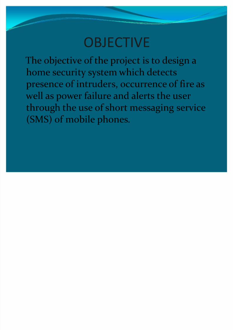
OBJECTIVEThe objective of the project is to design ahome security system which detects
presence of intruders, occurrence of fire as well as power failure and alerts the userthrough the use of short messaging service
(SMS) of mobile phones.
8/6/2019 Gsm Based Home Security
http://slidepdf.com/reader/full/gsm-based-home-security 3/23
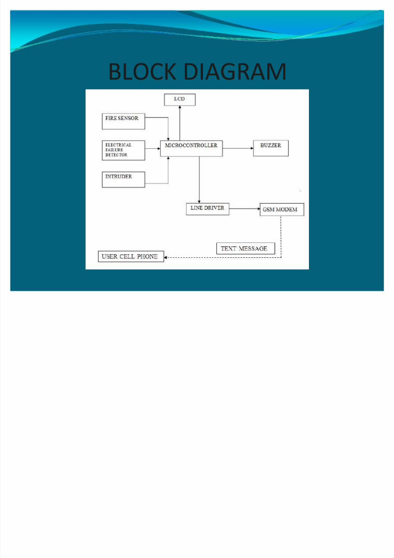
BLOCK DIAGRAM
8/6/2019 Gsm Based Home Security
http://slidepdf.com/reader/full/gsm-based-home-security 4/23
The GSM based home security system utilizes differentmodules which act concurrently in order to monitorthe domestic situation and alert the resident in case of emergency. A number of different sensor modules areutilized to monitor intruders, fire as well as powerfailure. The micro-controller module processes theinformation that it receives from the sensor modules
and decides the action to be taken. The LCD, buzzerand GSM modules alert the user regarding theemergency situation. The output of these threemodules depends on the micro-controller module.
8/6/2019 Gsm Based Home Security
http://slidepdf.com/reader/full/gsm-based-home-security 5/23
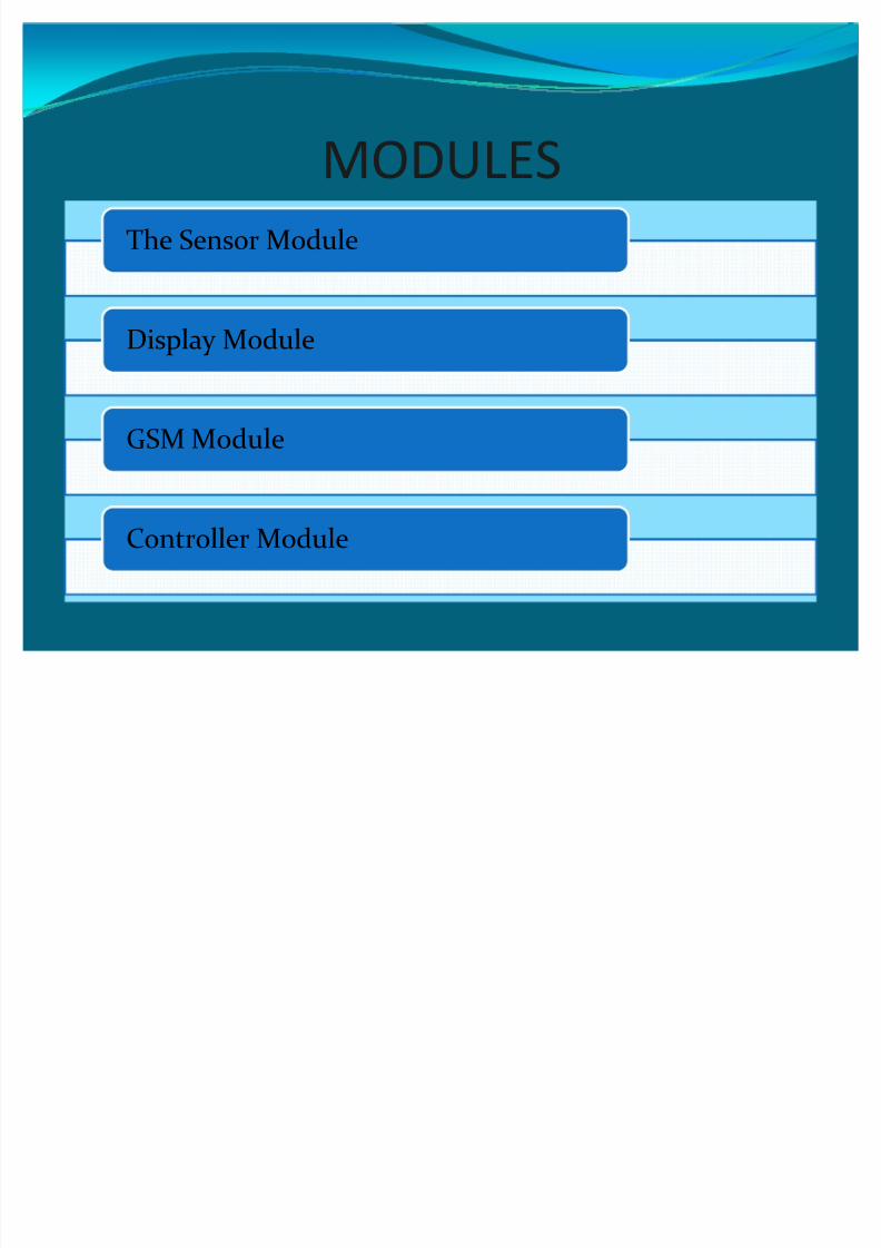
MODULES
The Sensor Module
Display Module
GSM Module
Controller Module
8/6/2019 Gsm Based Home Security
http://slidepdf.com/reader/full/gsm-based-home-security 6/23
SENSOR MODULEy The sensor module consists of a group of sensor for
monitoring different parameters.
FIRE SENSOR UNITELECTRIC FAILURE DETECTOR UNIT
INTRUDER UNIT
8/6/2019 Gsm Based Home Security
http://slidepdf.com/reader/full/gsm-based-home-security 7/23
DISPLAY MODULEThe display module is used to display theelectrical information so that it can be easily
understood by the user. A 16*2 LiquidCrystal Display is used as the display module in the system. It provides status
updates to the user so that the user is aware whether the system is in monitoring stateor it has detected some emergency situation
8/6/2019 Gsm Based Home Security
http://slidepdf.com/reader/full/gsm-based-home-security 8/23
GSM MODULEy GSM MODEM- it transmit the sms on receiving a
microcontroller command to the specified mobile
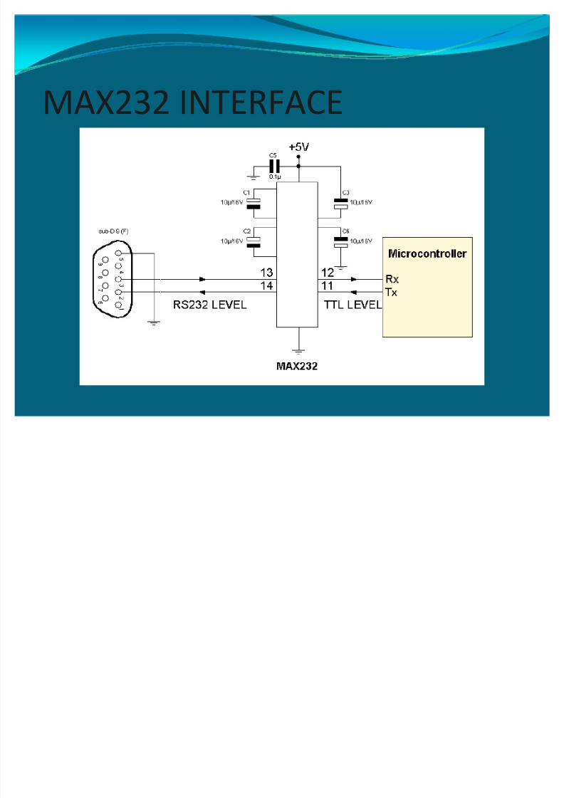
number.y LINE DRIVER- it converts the TTL logic into RS
232 logic. The PC connectors are used to get andsend the information through PCs ports.
8/6/2019 Gsm Based Home Security
http://slidepdf.com/reader/full/gsm-based-home-security 9/23
CONTROLLER MODULEy Microcontroller is used to monitor all the operations
in the system.
y It is a 40 pin IC. It takes the information and performsoperation according to present information.
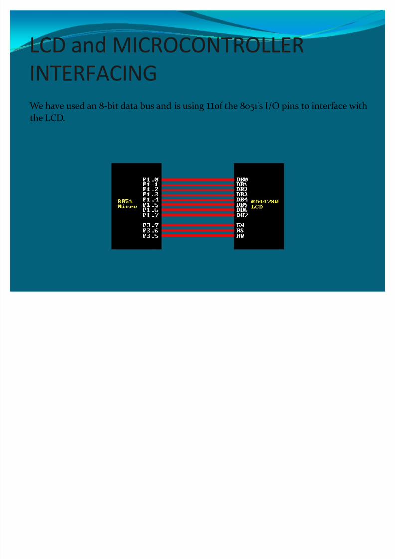
y In 40 pin AT89C51, there are four ports designated asP1, P2, P3 and P0. All these ports are 8-bit bi-directional
ports, i.e., they can be used as both input and outputports. These ports are also bit addressable and so theirbits can also be accessed individually.
8/6/2019 Gsm Based Home Security
http://slidepdf.com/reader/full/gsm-based-home-security 10/23
OPERATIONy The system is connected to a power supply sytem
y As soon as the connection are completed, the GSM modemsends a message to the user stating System On.
y At the same time, the LCD displays a welcome screenstating Home Security System
y After that, the LCD displays a status message "Monitoring.During this time, the system is monitoring the status of all
the sensors but has not yet encountered an emergency condition
y When any sensor detects an emergency state, for example,if there is an occurrence of fire, the thermistor sends asignal to the MCU

8/6/2019 Gsm Based Home Security
http://slidepdf.com/reader/full/gsm-based-home-security 11/23
�The MCU then sends information to the GSM modem to send
a text message to the user as well as concerned authorities
stating "Fire occurred at address xx´
�Simultaneously, the LCD starts to display an emergencymessage of ³Fire´ and the buzzer also starts ringing
�Similarly, in case an intruder is detected or power failure
occurs, the LCD, the buzzer and the GSM modem operate
simultaneously to alert the user and the concerned authoritiesregarding the same

8/6/2019 Gsm Based Home Security
http://slidepdf.com/reader/full/gsm-based-home-security 12/23
POWER SUPPLY
A power supply can by broken down into a series of blocks,each of which performs a particular function. In this project,
we are generating a 5V power supply .
8/6/2019 Gsm Based Home Security
http://slidepdf.com/reader/full/gsm-based-home-security 13/23
SENSOR MODULEy FIRE ALARM
In this fire alarm circuit, a thermistor works as theheat sensor. When temperature increases, its resistance
decreases, and vice versa. At normal temperature, theresistance of the thermistor is approximately 10 kilo-ohms, which reduces to a few ohms as the temperature increasesbeyond 100°C. When thermistor becomes hot, it provides alow-resistance path to extend positive voltage to the base of transistor via diode and resistor.
Diode provides a high-resistance (10-kilo-ohm) path whenthe thermistor connected to the positive supply coolsdown. It also stops the conduction of transistor. The circuit works off a 6V-12V regulated power supply. LED is used toindicate that power to the circuit is switched on.
8/6/2019 Gsm Based Home Security
http://slidepdf.com/reader/full/gsm-based-home-security 14/23
INTRUDERIn the intruder circuit the anode of the transmitter andreceiver (detector) are connected to the 5 V power
supply and cathode of the emitter is connected toground whereas that of receiver is connected to theground and trigger pin of the 555 timer i.e. pin no. 2.
When the bias voltage is applied to the infrared circuit,the transmitter emits the Infra-Red ray (IR). This ray receives the receiver (detector) and produced anoutput signal at pin 3 of the 555 timer.

8/6/2019 Gsm Based Home Security
http://slidepdf.com/reader/full/gsm-based-home-security 15/23
POWER FAILURE DETECTIONThe power failure alarm circuit that produces an alarm whenever the mains supply fails . In this circuit, when
power failure occurs, a pulse is sent to the P2.0 of themicrocontroller unit which in turn perform the task of turning on the buzzer and at the same time displayingmessage on LCD. In Addition to this, a signal is sent toGSM modem to send a message to a remote mobilethat power failure has occurred.
8/6/2019 Gsm Based Home Security
http://slidepdf.com/reader/full/gsm-based-home-security 16/23
8/6/2019 Gsm Based Home Security
http://slidepdf.com/reader/full/gsm-based-home-security 17/23
8/6/2019 Gsm Based Home Security
http://slidepdf.com/reader/full/gsm-based-home-security 18/23
GSM MODULEy The GSM modem is a highly flexible plug and play quad
band GSM modem for direct and easy integration to RS232.Supports features like Voice, Data/Fax, SMS, GPRS and
integrated TCP/IP stack. Here sms feature of GSM modemis used.INTERFACES:-y RS-232 through D-TYPE 9 pin connector, Serial port baud
rate adjustable 1200 to115200 bps (9600 default)y
Power supply through DC sockety SMA antenna connectory Push switch type SIM holdery LED status of GSM / GPRS module

8/6/2019 Gsm Based Home Security
http://slidepdf.com/reader/full/gsm-based-home-security 19/23
CONNECTING GSM MODEMy Insert SIM card: Press the yellow pin to remove the tray
from the SIM cardholder. After properly fixing the SIMcard in the tray, insert the tray in the slot provided.
y Connect Antenna: Screw the RF antenna on the RF cableoutput provided.
y Connect RS232 Cable: (Cable provided for RS232communication) Default baud rate is 9600 with 8-N-1,
no hardware handshaking. Cable provided has pins 7and 8 shorted that will set to no hardware handshaking.In you need hardware handshaking the pins 7-8 can betaken for signaling.
8/6/2019 Gsm Based Home Security
http://slidepdf.com/reader/full/gsm-based-home-security 20/23
MAX232 INTERFACE
8/6/2019 Gsm Based Home Security
http://slidepdf.com/reader/full/gsm-based-home-security 21/23
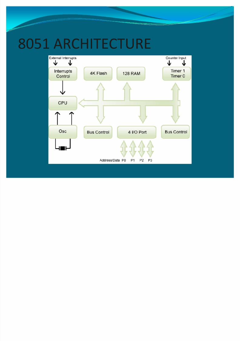
8051 ARCHITECTURE

8/6/2019 Gsm Based Home Security
http://slidepdf.com/reader/full/gsm-based-home-security 22/23
y 8051 act as a controlling block to monitor the workingof all the sensors and taking the necessary action.

8/6/2019 Gsm Based Home Security
http://slidepdf.com/reader/full/gsm-based-home-security 23/23
FUTURE SCOPEy The idea can be implemented to monitor all the
devices inside the house .
y
Using network interface all the houses in a city can belinked to a common database of the local authoritiesand any breach can be detected and appropriateaction taken accordingly.
y
The project can be extended to monitor the powerefficiency of each device and calculate the energy requirement in a house.