
GRUVLOK COUPLINGS FOR GROOVED-END · PDF file · 2015-09-14Gruvlok couplings for...
24
INTRODUCTION www.anvilintl.com 16 GRUVLOK ® COUPLINGS FOR GROOVED-END PIPE Gruvlok couplings for grooved-end pipe are available in nominal pipe sizes 1" thru 30" and metric sizes. The variety of coupling designs provide a universal means for the connection of pipe, fittings and pipe system components. The wide assortment of Gruvlok couplings and gaskets permit selection of the most suitable combination for a specific application, thus providing the most versatile and economical pipe system installation. MATERIAL SPECIFICATIONS ANSI BOLTS & HEAVY HEX NUTS: Heat treated, oval neck track head bolts conforming to ASTM A 183 Grade 2 with a minimum tensile strength of 110,000 psi and heavy hex nuts of carbon steel conforming to ASTM A 563 Grade A or Grade B, or J995 Grade 2. Bolts and nuts are provided zinc electroplated as standard. METRIC BOLTS & HEAVY HEX NUTS: Heat treated, zinc electroplated oval-neck track head bolts made of carbon steel with mechanical properties per ISO 898-1 Class 8.8. Hex nuts are zinc electroplated followed by a yellow chromate dip. STAINLESS STEEL BOLTS & NUTS: Stainless steel bolts and nuts are available for the Fig. 7001, 7401, 7401-2, 7001-2, 7004, 7000 and 7400 couplings in standard 304SS, (316SS available as special order) HOUSING: Ductile Iron conforming to ASTM A 536, Grade 65-45-12 COATINGS: Rust inhibiting paint Color: ORANGE (standard) Hot Dipped Zinc Galvanized (optional) Other Colors Available (IE: RAL3000 and RAL9000) For other Coating requirements contact an Anvil Representative. GASKETS: Materials Properties as designated in accordance with ASTM D 2000 GRADE “EP” EPDM (Green/Red color code) NSF-61 Certified -40°F to 250°F (Service Temperature Range)(-40°C to 121°C) Recommended for water service, diluted acids, alkalies solutions, oil-free air and many other chemical services. NOT FOR USE IN PETROLEUM APPLICATIONS. GRADE “E” EPDM (Green color code) NSF-61 Certified -40°F to 230°F (Service Temperature Range)(-40°C to 110°C) Recommended for water service, diluted acids, alkalies solutions, oil-free air and many chemical services. NOT FOR USE IN PETROLEUM APPLICATIONS. Grade “T” Nitrile (Orange color code) -20°F to 180°F (Service Temperature Range)(-29°C to 82°C) Recommended for petroleum applications. Air with oil vapors and vegetable and mineral oils. NOT FOR USE IN HOT WATER OR HOT AIR Grade “O” Fluoro-Elastomer (Blue color code) Size Range: 1" - 12" (C style only) 20°F to 300°F (Service Temperature Range)(-29°C to 149°C) Recommended for high temperature resistance to oxidizing acids, petroleum oils, hydraulic fluids, halogenated hydrocarbons and lubricants Grade “L” Silicone (Red color code) Size Range: 1" - 12" (C style only) -40°F to 350°F (Service Temperature Range)(-40°C to 177°C) Recommended for dry, hot air and some high temperature chemical services GASKET TYPE: Standard C Style Flush Gap: 1" - 24" End Guard: 1" - 12" (Fig. 7004 and 7377) SlideLOK: 2" - 8" LUBRICATION: Standard Gruvlok Gruvlok Xtreme TM (Do Not use with Grade “L”) WORKING PRESSURE, END LOAD, PIPE END SEPARATION & DEFLECTION FROM CENTER LINE: Based on standard wall steel pipe with cut or roll grooves in accordance with Gruvlok specifications. See technical data section for design factors. GL-3.14
Transcript of GRUVLOK COUPLINGS FOR GROOVED-END · PDF file · 2015-09-14Gruvlok couplings for...

INTRODUCTION
www.anvilintl.com16
GRUVLOK® COUPLINGS FOR GROOVED-END PIPEGruvlok couplings for grooved-end pipe are available in nominal pipe sizes 1" thru 30" and metric sizes. The variety of coupling designs provide a universal means for the connection of pipe, fittings and pipe system components. The wide assortment of Gruvlok couplings and gaskets permit selection of the most suitable combination for a specific application, thus providing the most versatile and economical pipe system installation.
MATERIAL SPECIFICATIONS
ANSI BOLTS & HEAVY HEX NUTS:Heat treated, oval neck track head bolts conforming to ASTM A 183 Grade 2 with a minimum tensile strength of 110,000 psi and heavy hex nuts of carbon steel conforming to ASTM A 563 Grade A or Grade B, or J995 Grade 2. Bolts and nuts are provided zinc electroplated as standard.
METRIC BOLTS & HEAVY HEX NUTS:Heat treated, zinc electroplated oval-neck track head bolts made of carbon steel with mechanical properties per ISO 898-1 Class 8.8. Hex nuts are zinc electroplated followed by a yellow chromate dip.
STAINLESS STEEL BOLTS & NUTS:Stainless steel bolts and nuts are available for the Fig. 7001, 7401, 7401-2, 7001-2, 7004, 7000 and 7400 couplings in standard 304SS, (316SS available as special order)
HOUSING:Ductile Iron conforming to ASTM A 536, Grade 65-45-12
COATINGS:Rust inhibiting paint Color: ORANGE (standard)Hot Dipped Zinc Galvanized (optional)Other Colors Available (IE: RAL3000 and RAL9000)For other Coating requirements contact an Anvil Representative.
GASKETS: MaterialsProperties as designated in accordance with ASTM D 2000
GRADE “EP” EPDM (Green/Red color code) NSF-61 Certified-40°F to 250°F (Service Temperature Range)(-40°C to 121°C)Recommended for water service, diluted acids, alkalies solutions, oil-free air and many other chemical services.NOT FOR USE IN PETROLEUM APPLICATIONS.
GRADE “E” EPDM (Green color code) NSF-61 Certified-40°F to 230°F (Service Temperature Range)(-40°C to 110°C)Recommended for water service, diluted acids, alkalies solutions, oil-free air and many chemical services.
NOT FOR USE IN PETROLEUM APPLICATIONS.
Grade “T” Nitrile (Orange color code)-20°F to 180°F (Service Temperature Range)(-29°C to 82°C)Recommended for petroleum applications. Air with oil vapors andvegetable and mineral oils.NOT FOR USE IN HOT WATER OR HOT AIR
Grade “O” Fluoro-Elastomer (Blue color code)Size Range: 1" - 12" (C style only)20°F to 300°F (Service Temperature Range)(-29°C to 149°C)Recommended for high temperature resistance to oxidizing acids,petroleum oils, hydraulic fluids, halogenated hydrocarbons and lubricants
Grade “L” Silicone (Red color code)Size Range: 1" - 12" (C style only)-40°F to 350°F (Service Temperature Range)(-40°C to 177°C)Recommended for dry, hot air and some high temperature chemical services
GASKET TYPE:Standard C StyleFlush Gap: 1" - 24"End Guard: 1" - 12" (Fig. 7004 and 7377)SlideLOK: 2" - 8"
LUBRICATION:Standard GruvlokGruvlok XtremeTM (Do Not use with Grade “L”)
WORKING PRESSURE, END LOAD, PIPE END SEPARATION & DEFLECTION FROM CENTER LINE:Based on standard wall steel pipe with cut or roll grooves in accordance with Gruvlok specifications. See technical data section for design factors.
GL-3.14

INTRODUCTION
www.anvilintl.com 17
Intro
duct
ion
Coup
lings
Outle
tsFi
tting
sVa
lves
&
Acce
ssor
ies
High
Pres
sure
Di-E
lect
ricNi
pple
sPl
ain-
End
Fitti
ngs
HDPE
Coup
lings
Sock
-It®
Fitti
ngs
Stai
nles
sSt
eel M
etho
dRo
ll Gr
oove
rsIn
stal
latio
n&
Ass
embl
ySp
ecia
lCo
atin
gsDe
sign
Serv
ices
Tech
nica
lDa
taM
aste
r For
mat
3 Pa
rt Sp
ecs.
Pict
oria
lIn
dex
CTS
Copp
er
Syst
em
Gruvlok Couplings are identified by either the nominal ANSI pipe size in inches or pipe O.D. in millimeters (see column 2).
Nominal Outside Diameter of Pipe.
Maximum line pressure, including surge, to which a joint can be subjected. Working pressure ratings are based on standard wall steel pipe with standard cut or roll grooves in accordance with Gruvlok specifications. For Performance Data on other than standard wall pipe, refer to Technical data section. NOTE: For one time field test only, the maximum joint working pressure may be increased to 1.5 times the figure shown unless otherwise noted.
Maximum end load from all interior and/or exterior forces to which the joint can be subjected are based on standard wall steel pipe with standard cut or roll grooves in accordance with Gruvlok specifications.
Range of pipe end separation for roll grooved pipe, Double values shown when using cut groove pipe; see page 204 for details.
Maximum allowable angular deflection values from centerline when using standard roll grooved pipe; Double values shown when using cut groove pipe; see page 204 for details.
“X”, “Y”, and “Z” are external dimensions for reference purposes only.
The quantity of bolts per coupling.
Nuts must be tightened alternating and evenly to the specified bolt torque. See individual product installation instructions for additional important information.
Approximate weight for a fully assembled coupling with gasket, bolts, and nuts.
COUPLING DATA CHART NOTES
COUPLING DATA CHART NOTES
Nominal Size O.D. Max. Work.
PressureMax. End
LoadRange of Pipe End
Separation
Deflection from CL Coupling Dimensions Coupling Bolts Specified Torque Approx. Wt. Ea.Per Coupling of Pipe X Y Z Qty. Size Min. Max.
In./DN(mm) In./mm PSI/bar Lbs./kN In./mm Degrees(˚)-Minutes(') In./ft-mm/m In./mm In./mm In./mm In./mm Ft.-Lbs/N-m Lbs./kg
1 2 3 4 5 6 7 8 9 10
1
2
3
4
5
6
7
8
9
10
GL-8.14

COUPLINGS FOR GROOVED-END PIPE
www.anvilintl.com18
For Listings/Approval Details and Limitations,visit our website at www.anvilintl.com orcontact an Anvil® Sales Representative.
FIG. 7401Rigidlok® Coupling
MATERIAL SPECIFICATIONS
ANSI BOLTS & HEAVY HEX NUTS:Heat treated, oval neck track head bolts conforming to ASTM A 183 Grade 2 with a minimum tensile strength of 110,000 psi and heavy hex nuts of carbon steel conforming to ASTM A 563 Grade A or Grade B, or J995 Grade 2. Bolts and nuts are provided zinc electroplated as standard.
METRIC BOLTS & HEAVY HEX NUTS:Heat treated, zinc electroplated oval-neck track head bolts made of carbon steel with mechanical properties per ISO 898-1 Class 8.8. Hex nuts are zinc electroplated followed by a yellow chromate dip.
STAINLESS STEEL BOLTS & NUTS:304SS Stainless Steel bolts and nuts are available as a standard option. (316SS are available for special order).
HOUSING:Ductile Iron conforming to ASTM A 536, Grade 65-45-12
COATINGS:Rust inhibiting paint – Color: ORANGE (standard)Hot Dipped Zinc Galvanized (optional)Other Colors Available (IE: RAL3000 and RAL9000)For other Coating requirements contact an Anvil Representative.
GASKETS: MaterialsProperties as designated in accordance with ASTM D 2000
Grade “EP” EPDM (Green and Red color code)-40°F to 250°F (Service Temperature Range)(-40°C to 121°C)Recommended for water service, diluted acids, alkalies solutions, oil-free air and many other chemical services.NOT FOR USE IN PETROLEUM APPLICATIONS.
For hot water applications the use of Gruvlok Extreme Temperature lubricant is recommended. NSF-61 Certified for cold and hot water applications up through 12".
Grade “T” Nitrile (Orange color code)-20°F to 180°F (Service Temperature Range)(-29°C to 82°C)Recommended for petroleum applications. air with oil vapors andvegetable and mineral oils.NOT FOR USE IN HOT WATER OR HOT AIR
Grade “O” Fluoro-Elastomer (Blue color code)Size Range: 1" - 12" (C style only)20°F to 300°F (Service Temperature Range)(-29°C to 149°C)Recommended for high temperature resistance to oxidizing acids,petroleum oils, hydraulic fluids, halogenated hydrocarbons and lubricants.
Grade “L” Silicone (Red color code)Size Range: 1" - 12" (C style only)-40°F to 350°F (Service Temperature Range)(-40°C to 177°C)Recommended for dry, hot air and some high temperature chemicalservices. Contact an Anvil Representative for availability.
GASKET TYPE:C Style (1" - 24")Flush Gap (1" - 24")
LUBRICATION:StandardGruvlok XtremeTM (Do Not use with Grade “L”)
The Fig. 7401 Rigidlok Coupling from Gruvlok provides a rigid pipe connection. Rigidity is attained simply; it is designed in.
The Fig. 7401 Rigidlok coupling utilizes a technologically advanced housing design that conforms to and grips the pipe. With the Fig. 7401 there emerges a new generation of rigid couplings.
Coupling installation is fast and easy, remove only one nut and swing the housing over the gasket and into the grooves. The exclusive Guidelok® feature automatically separates the grooved pipe ends and guides the coupling into position as the bolts are tightened. Precisely sized and oriented tines in the housing key section firmly grip the pipe. The combination of these designed in features produce a secure, rigid pipe joint connection.
This coupling is an ideal connector for service and applications that require a rigid connection.
The Fig. 7401 Rigidlok Coupling is designed for use with roll grooved or cut grooved standard weight and roll grooved lightweight pipe, as well as with grooved-end fittings and valves. The Rigidlok Coupling maintains a rigid connection with
support and hanging in conformance with applicable ANSI B31.1 Power Piping Code, ANSI B31.9 Building Service Pipe Code as well as NFPA 13 sprinkler systems.
The Fig. 7401 Rigidlok Coupling allows for working pressure ratings to 750 psi (51.7 bar) when used on standard wall roll or cut grooved pipe.
GL-3.14
COUPLINGS FOR GROOVED-END PIPE
www.anvilintl.com 19
Intro
duct
ion
Coup
lings
Outle
tsFi
tting
sVa
lves
&
Acce
ssor
ies
High
Pres
sure
Di-E
lect
ricNi
pple
sPl
ain-
End
Fitti
ngs
HDPE
Coup
lings
Sock
-It®
Fitti
ngs
Stai
nles
sSt
eel M
etho
dRo
ll Gr
oove
rsIn
stal
latio
n&
Ass
embl
ySp
ecia
lCo
atin
gsDe
sign
Serv
ices
Tech
nica
lDa
taM
aste
r For
mat
3 Pa
rt Sp
ecs.
Pict
oria
lIn
dex
CTS
Copp
er
Syst
em
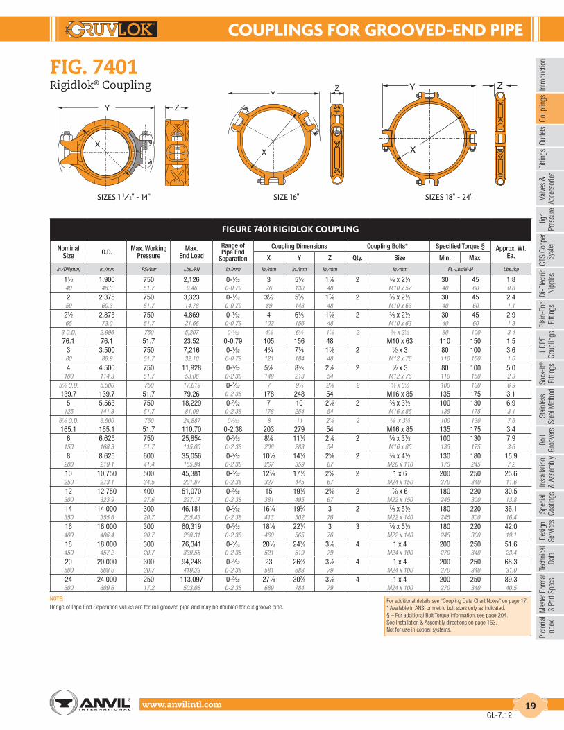
SIZES 1 1/2" - 14" SIZE 16" SIZES 18" - 24"
FIG. 7401Rigidlok® Coupling
FIGURE 7401 RIGIDLOK COUPLING
Nominal Size O.D. Max. Working
PressureMax.
End Load
Range of Pipe End
Separation
Coupling Dimensions Coupling Bolts* Specified Torque § Approx. Wt. Ea.X Y Z Qty. Size Min. Max.
In./DN(mm) In./mm PSI/bar Lbs./kN In./mm In./mm In./mm In./mm In./mm Ft.-Lbs/N-M Lbs./kg
11⁄2 1.900 750 2,126 0-1⁄32 3 51⁄8 17⁄8 2 3⁄8 x 21⁄4 30 45 1.840 48.3 51.7 9.46 0-0.79 76 130 48 M10 x 57 40 60 0.8
2 2.375 750 3,323 0-1⁄32 31⁄2 55⁄8 17⁄8 2 3⁄8 x 21⁄2 30 45 2.450 60.3 51.7 14.78 0-0.79 89 143 48 M10 x 63 40 60 1.1
21⁄2 2.875 750 4,869 0-1⁄32 4 61⁄8 17⁄8 2 3⁄8 x 21⁄2 30 45 2.965 73.0 51.7 21.66 0-0.79 102 156 48 M10 x 63 40 60 1.3
3 O.D. 2.996 750 5,207 0-1⁄32 41⁄8 61⁄8 17⁄8 2 3⁄8 x 21⁄2 80 100 3.476.1 76.1 51.7 23.52 0-0.79 105 156 48 M10 x 63 110 150 1.5
3 3.500 750 7,216 0-1⁄32 43⁄4 71⁄4 17⁄8 2 1⁄2 x 3 80 100 3.680 88.9 51.7 32.10 0-0.79 121 184 48 M12 x 76 110 150 1.6
4 4.500 750 11,928 0-3⁄32 57⁄8 83⁄8 21⁄8 2 1⁄2 x 3 80 100 5.0100 114.3 51.7 53.06 0-2.38 149 213 54 M12 x 76 110 150 2.3
51⁄2 O.D. 5.500 750 17,819 0-3⁄32 7 93⁄4 21⁄8 2 5⁄8 x 31⁄2 100 130 6.9139.7 139.7 51.7 79.26 0-2.38 178 248 54 M16 x 85 135 175 3.1
5 5.563 750 18,229 0-3⁄32 7 10 21⁄8 2 5⁄8 x 31⁄2 100 130 6.9125 141.3 51.7 81.09 0-2.38 178 254 54 M16 x 85 135 175 3.1
61⁄2 O.D. 6.500 750 24,887 0-3⁄32 8 11 21⁄8 2 5⁄8 x 31⁄2 100 130 7.6165.1 165.1 51.7 110.70 0-2.38 203 279 54 M16 x 85 135 175 3.4
6 6.625 750 25,854 0-3⁄32 81⁄8 111⁄8 21⁄8 2 5⁄8 x 31⁄2 100 130 7.9150 168.3 51.7 115.00 0-2.38 206 283 54 M16 x 85 135 175 3.6
8 8.625 600 35,056 0-3⁄32 101⁄2 141⁄8 25⁄8 2 3⁄4 x 41⁄2 130 180 15.9200 219.1 41.4 155.94 0-2.38 267 359 67 M20 x 110 175 245 7.2
10 10.750 500 45,381 0-3⁄32 127⁄8 171⁄2 25⁄8 2 1 x 6 200 250 25.6250 273.1 34.5 201.87 0-2.38 327 445 67 M24 x 150 270 340 11.6
12 12.750 400 51,070 0-3⁄32 15 191⁄2 25⁄8 2 7⁄8 x 6 180 220 30.5300 323.9 27.6 227.17 0-2.38 381 495 67 M22 x 150 245 300 13.8
14 14.000 300 46,181 0-3⁄32 161⁄4 193⁄4 3 2 7⁄8 x 51⁄2 180 220 36.1350 355.6 20.7 205.43 0-2.38 413 502 76 M22 x 140 245 300 16.4
16 16.000 300 60,319 0-3⁄32 181⁄8 221⁄4 3 3 7⁄8 x 51⁄2 180 220 42.0400 406.4 20.7 268.31 0-2.38 460 565 76 M22 x 140 245 300 19.1
18 18.000 300 76,341 0-3⁄32 201⁄2 243⁄8 31⁄8 4 1 x 4 200 250 51.6450 457.2 20.7 339.58 0-2.38 521 619 79 M24 x 100 270 340 23.4
20 20.000 300 94,248 0-3⁄32 23 267⁄8 31⁄8 4 1 x 4 200 250 68.3500 508.0 20.7 419.23 0-2.38 581 683 79 M24 x 100 270 340 31.0
24 24.000 250 113,097 0-3⁄32 271⁄8 307⁄8 31⁄8 4 1 x 4 200 250 89.3600 609.6 17.2 503.08 0-2.38 689 784 79 M24 x 100 270 340 40.5
Y Z
X
YZ
X
Y Z
X
GL-7.12
For additional details see “Coupling Data Chart Notes” on page 17.* Available in ANSI or metric bolt sizes only as indicated.§ – For additional Bolt Torque information, see page 204.See Installation & Assembly directions on page 163.Not for use in copper systems.
NOTE:Range of Pipe End Seperation values are for roll grooved pipe and may be doubled for cut groove pipe.

COUPLINGS FOR GROOVED-END PIPE
www.anvilintl.com20
FIG. 7401-2Rigidlok® Coupling
GL-3.14
FIGURE 7401-2 RIGIDLOK COUPLING
Nominal Size O.D.
Max. Working Pressure
Max. End Load
Range of Pipe End
Separation
Coupling Dimensions Coupling Bolts* Specified Torque § Approx. Wt. Ea.X Y Z Qty. Size Min. Max.
In./DN(mm) In./mm PSI/bar Lbs./kN In./mm In./mm In./mm In./mm In./mm Ft.-Lbs/N-M Lbs./kg
14 14.000 350 53,878 0-3⁄32 161⁄4 193⁄4 3 2 7⁄8 x 51⁄2 180 220 36.5350 355.6 24.1 239.66 0-2.38 413 502 76 – 245 300 16.6
16 16.000 350 70,372 0-3⁄32 185⁄16 22 3 2 1 x 51⁄2 250 300 46.0400 406.4 24.1 313.03 0-2.38 465 558 76 – 340 408 20.9
18 18.000 350 89,064 0-3⁄32 203⁄4 241⁄4 31⁄8 2 1 x 51⁄2 250 300 62.5450 457.2 24.1 396.18 0-2.38 527 615 79 – 340 408 28.3
20 20.000 350 109,956 0-3⁄32 23 271⁄8 31⁄8 2 11⁄8 x 51⁄2 375 425 73.5500 508.0 24.1 489.11 0-2.38 582 691 79 – 510 578 33.3
24 24.000 350 158,336 0-3⁄32 271⁄4 311⁄8 33⁄16 2 11⁄8 x 51⁄2 375 425 90.5600 609.6 24.1 704.31 0-2.38 688 791 81 – 510 578 41.1
Range of Pipe End Separation values are for roll grooved pipe and may be doubled for cut groove pipe.See Installation & Assembly directions on page 167.
Z
X
Y
Gruvlok® introduces new 2-piece large diameter standard groove couplings in both rigid and flexible styles
• Uses standard grooves (conforming to AWWA C-606)• No special grooves or grooving tools needed• Pressures to 350 P.S.I. on cut or roll grooved pipe with a wall
thickness of 0.250" or greater• No special fittings needed• No special valves needed• Up to 23% less weight than competitive models• Sizes: 14" through 24" in Rigid: Figure 7401-2
MATERIAL SPECIFICATIONS
ANSI BOLTS & HEAVY HEX NUTS:Heat treated, oval neck track head bolts conforming to ASTM A 183 Grade 2 with a minimum tensile strength of 110,000 psi and heavy hex nuts of carbon steel conforming to ASTM A 563 Grade A or Grade B, or J995 Grade 2. Bolts and nuts are provided zinc electroplated as standard.
STAINLESS STEEL BOLTS & NUTS:304SS Stainless Steel bolts and nuts are available as a standard option. (316SS are available for special order).
HOUSING:Ductile Iron conforming to ASTM A 536, Grade 65-45-12
COATINGS:Rust inhibiting paint – Color: ORANGE (standard)Hot Dipped Zinc Galvanized (optional)Other Colors Available (IE: RAL3000 and RAL9000)For other Coating requirements contact an Anvil Representative.
GASKETS: MaterialsProperties as designated in accordance with ASTM D 2000
Grade “E” EPDM (Green color code)-40°F to 230°F (Service Temperature Range)(-40°C to 110°C)Recommended for water service, diluted acids, alkalies solutions, oil-free air and many other chemical services.NOT FOR USE IN PETROLEUM APPLICATIONS.
Grade “T” Nitrile (Orange color code)-20°F to 180°F (Service Temperature Range)(-29°C to 82°C)Recommended for petroleum applications. Air with oil vapors andvegetable and mineral oils.NOT FOR USE IN HOT WATER OR HOT AIR
GASKET TYPE:Flush Gap (Standard)
LUBRICATION:StandardGruvlok XtremeTM
WORKING PRESSURE, END LOAD & PIPE END SEPARATION:Based on standard wall steel pipe with cut or roll grooves in accordance with Gruvlok specifications. See technical data section for design factors.

COUPLINGS FOR GROOVED-END PIPE
www.anvilintl.com 21
Intro
duct
ion
Coup
lings
Outle
tsFi
tting
sVa
lves
&
Acce
ssor
ies
High
Pres
sure
Di-E
lect
ricNi
pple
sPl
ain-
End
Fitti
ngs
HDPE
Coup
lings
Sock
-It®
Fitti
ngs
Stai
nles
sSt
eel M
etho
dRo
ll Gr
oove
rsIn
stal
latio
n&
Ass
embl
ySp
ecia
lCo
atin
gsDe
sign
Serv
ices
Tech
nica
lDa
taM
aste
r For
mat
3 Pa
rt Sp
ecs.
Pict
oria
lIn
dex
CTS
Copp
er
Syst
em
The SlideLOK coupling is a ready for installation coupling designed to reduce installation time. The slide action allows for greater flexibility during installation. The patented gasket provides four separate sealing surfaces for added protection. The engineered metal-to-metal installation requirement is a quick and easy indication of proper assembly.
The SlideLOK is designed to be used with roll groove or cut groove steel pipe, as well as with grooved light wall pipe, Gruvlok® grooved-end fittings, and valves. The SlideLOK coupling produces a secure, rigid pipe joint connection.
The SlideLOK coupling allows for a maximum working pressure of 750 psi on roll or cut grooved standard wall pipe. Contact an Anvil representative for light wall pipe pressure ratings.
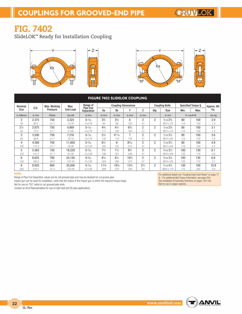
FIG. 7402SlideLOK™ Ready for Installation Coupling
MATERIAL SPECIFICATIONS
ANSI BOLTS & HEAVY HEX NUTS:Heat treated, oval neck track head bolts conforming to ASTM A 183 Grade 2 with a minimum tensile strength of 110,000 psi and heavy hex nuts of carbon steel conforming to ASTM A 563 Grade A or Grade B, or J995 Grade 2. Bolts and nuts are provided zinc electroplated as standard.
HOUSING:Ductile Iron conforming to ASTM A 536, Grade 65-45-12
COATINGS:Rust inhibiting paint Color: ORANGE (standard)Hot Dipped Zinc Galvanized (optional)
GASKETS: MaterialsProperties as designated in accordance with ASTM D 2000
Grade “EP” EPDM (Green and Red color code)-40°F to 250°F (Service Temperature Range)(-40°C to 121°C)Recommended for water service, diluted acids, alkalies solutions, oil-free air and many other chemical services.NOT FOR USE IN PETROLEUM APPLICATIONS.
Grade “T” Nitrile (Orange color code)-20°F to 180°F (Service Temperature Range)(-29°C to 82°C)Recommended for petroleum applications. air with oil vapors andvegetable and mineral oils.NOT FOR USE IN HOT WATER OR HOT AIR
GASKET TYPE:SlideLOK (2" - 8")
LUBRICATION:StandardGruvlok XtremeTM
SlideLOK PressureResponsive Gasket
GL-3.14
Patent D680629, D680630, D696751
COUPLINGS FOR GROOVED-END PIPE
www.anvilintl.com22
ZY
Xa
FIGURE 7402 SLIDELOK COUPLING
Nominal Size O.D. Max. Working
PressureMax.
End Load
Range of Pipe End
Separation
Coupling Dimensions Coupling Bolts Specified Torque § Approx. Wt. Ea.Xa Xb Y Z Qty. Size Min. Max.
In./DN(mm) In./mm PSI/bar Lbs./kN In./mm In./mm In./mm In./mm In./mm In./mm Ft.-Lbs/N-M Lbs./kg
2 2.375 750 3,323 0-1⁄32 33⁄4 33⁄8 6 2 2 1⁄2 x 23⁄4 80 100 2.950 60.3 51.7 14.78 0-0.79 95 86 152 51 M12 x 70 110 150 1.3
21⁄2 2.875 750 4,869 0-1⁄32 45⁄8 41⁄4 63⁄8 2 2 1⁄2 x 23⁄4 80 100 3.165 73.0 51.7 21.66 0-0.79 117 108 163 51 M12 x 70 110 150 1.4
3 3.500 750 7,216 0-1⁄32 51⁄5 411⁄16 7 2 2 1⁄2 x 31⁄2 80 100 3.680 88.9 51.7 32.10 0-0.79 132 119 178 51 M12 x 89 110 150 1.6
4 4.500 750 11,928 0-3⁄32 61⁄2 6 85⁄16 2 2 1⁄2 x 31⁄2 80 100 4.9100 114.3 51.7 53.06 0-2.38 165 152 212 51 M12 x 89 110 150 2.2
5 5.563 750 18,229 0-3⁄32 73⁄4 71⁄8 93⁄4 2 2 5⁄8 x 31⁄2 100 130 6.1125 141.3 51.7 81.09 0-2.38 196 181 248 51 M16 x 89 135 175 2.8
6 6.625 700 24,130 0-3⁄32 87⁄8 81⁄5 104⁄5 2 2 5⁄8 x 31⁄2 100 130 6.8150 168.3 48.3 107.34 0-2.38 224 208 274 51 M16 x 89 135 175 3.1
8 8.625 600 35,056 0-3⁄32 113⁄8 105⁄8 132⁄5 21⁄2 2 3⁄4 x 41⁄2 130 180 10.9200 219.1 41.4 155.94 0-2.38 289 270 340 64 M20 x 115 175 245 4.9
For additional details see “Coupling Data Chart Notes” on page 17.§ – For additional Bolt Torque information, see page 204.See Installation & Assembly directions on pages 164-165.Not for use in copper systems.
NOTES:Range of Pipe End Separation values are for roll grooved pipe and may be doubled for cut groove pipe.Impact gun can be used for installation, verify that the output of the impact gun is within the required torque range.Not for use on "EG" rolled or cut grooved pipe ends.Contact an Anvil Representative for use on light wall and SS pipe applications.
FIG. 7402SlideLOK™ Ready for Installation Coupling
ZY
Xb
GL-Rev

COUPLINGS FOR GROOVED-END PIPE
www.anvilintl.com 23
Intro
duct
ion
Coup
lings
Outle
tsFi
tting
sVa
lves
&
Acce
ssor
ies
High
Pres
sure
Di-E
lect
ricNi
pple
sPl
ain-
End
Fitti
ngs
HDPE
Coup
lings
Sock
-It®
Fitti
ngs
Stai
nles
sSt
eel M
etho
dRo
ll Gr
oove
rsIn
stal
latio
n&
Ass
embl
ySp
ecia
lCo
atin
gsDe
sign
Serv
ices
Tech
nica
lDa
taM
aste
r For
mat
3 Pa
rt Sp
ecs.
Pict
oria
lIn
dex
CTS
Copp
er
Syst
em
The Gruvlok® Fig. 7001 Coupling forms a flexible grooved end pipe joint connection with the versatility for a wide range of applications. Services include mechanical and plumbing, process piping, mining and oil field piping, and many others. The coupling design supplies optimum strength for working pressures to 1000 PSl (69 bar) without excessive casting weight.
The flexible design eases pipe and equipment installation while providing the designed-in benefit of reducing pipeline noise and vibration transmission without the addition of special components. To ease coupling handling and assembly and to assure consistent quality, sizes 1" through 14" couplings have two 180° segment housings, 16" have three 120˚ segment housings, and 18" through 24" sizes have four 90° segment housings, while the 28" O.D. and 30" O.D. couplings have six 60° segment housings. The 28" O.D. and 30" O.D. are weld-ring couplings.
For Listings/Approval Details and Limitations,visit our website at www.anvilintl.com orcontact an Anvil® Sales Representative.
FIG. 7001Flexible Coupling
MATERIAL SPECIFICATIONS
ANSI BOLTS & HEAVY HEX NUTS:Heat treated, oval neck track head bolts conforming to ASTM A 183 Grade 2 with a minimum tensile strength of 110,000 psi and heavy hex nuts of carbon steel conforming to ASTM A 563 Grade A or Grade B, or J995 Grade 2. Bolts and nuts are provided zinc electroplated as standard.
METRIC BOLTS & HEAVY HEX NUTS:Heat treated, zinc electroplated oval-neck track head bolts made of carbon steel with mechanical properties per ISO 898-1 Class 8.8. Hex nuts are zinc electroplated followed by a yellow chromate dip.
STAINLESS STEEL BOLTS & NUTS:304SS Stainless Steel bolts and nuts are available as a standard option. (316SS are available for special order).
HOUSING:Ductile Iron conforming to ASTM A 536, Grade 65-45-12
COATINGS:Rust inhibiting paint – Color: ORANGE (standard)Hot Dipped Zinc Galvanized (optional)Other Colors Available (IE: RAL3000 and RAL9000)For other Coating requirements contact an Anvil Representative.
GASKETS: MaterialsProperties as designated in accordance with ASTM D 2000
Grade “EP” EPDM (Green and Red color code)-40°F to 250°F (Service Temperature Range)(-40°C to 121°C)Recommended for water service, diluted acids, alkalies solutions, oil-free air and many other chemical services.NOT FOR USE IN PETROLEUM APPLICATIONS.
For hot water applications the use of Gruvlok Extreme Temperature lubricant is recommended. NSF-61 Certified for cold and hot water applications up through 12".
Grade “T” Nitrile (Orange color code)-20°F to 180°F (Service Temperature Range)(-29°C to 82°C)Recommended for petroleum applications. Air with oil vapors andvegetable and mineral oils.NOT FOR USE IN HOT WATER OR HOT AIR
Fig. 7001 withFlush Gap Gasket
Fig. 7001 withStandard Gasket
Grade “O” Fluoro-Elastomer (Blue color code)Size Range: 1" - 12" (C style only)20°F to 300°F (Service Temperature Range)(-29°C to 149°C)Recommended for high temperature resistance to oxidizing acids,petroleum oils, hydraulic fluids, halogenated hydrocarbons and lubricants.
Grade “L” Silicone (Red color code)Size Range: 1" - 12" (C style only)-40°F to 350°F (Service Temperature Range)(-40°C to 177°C)Recommended for dry, hot air and some high temperature chemical services. Contact an Anvil Representative for availability.
GASKET TYPE:C Style (1" - 30")Flush Gap (1" - 24")
LUBRICATION:StandardGruvlok XtremeTM (Do Not use with Grade “L”)
WORKING PRESSURE, END LOAD, PIPE END SEPARATION & DEFLECTION FROM CENTER LINE:Based on standard wall steel pipe with cut or roll grooves in accordance with Gruvlok specifications. See technical data section for design factors.
GL-3.14

COUPLINGS FOR GROOVED-END PIPE
www.anvilintl.com24
FIG. 7001Flexible Coupling
SIZES 1" - 14" SIZES 16" - 24" SIZES 28" - 30"
FIGURE 7001 FLEXIBLE COUPLING
Nominal Size O.D. Max. Work.
PressureMax. End
LoadRange of Pipe End
Separation
Deflection from CL Coupling Dimensions Bolt Dimensions* Specified Torque § Approx. Wt. Ea.Per Coupling of Pipe X Y Z Qty. Size Min. Max.
In./DN(mm) In./mm PSI/bar Lbs./kN In./mm Degrees(˚)-Minutes(') In./ft-mm/m In./mm In./mm In./mm In./mm Ft.-Lbs/N-m Lbs./kg
1 1.315 1000 1,358 0-1⁄32 1° 22' 0.29 21⁄2 41⁄2 17⁄8 2 3⁄8 x 21⁄4 30 45 1.325 33.4 68.9 6.04 0-0.79 23.8 64 114 48 M10 x 57 40 60 0.611⁄4 1.660 1000 2,164 0-1⁄32 1° 5' 0.23 23⁄4 41⁄2 17⁄8 2 3⁄8 x 21⁄4 30 45 1.432 42.2 68.9 9.63 0-0.79 18.8 70 114 48 M10 x 57 40 60 0.611⁄2 1.900 1000 2,835 0-1⁄32 0° 57' 0.20 3 45⁄8 17⁄8 2 3⁄8 x 21⁄4 30 45 1.540 48.3 68.9 12.61 0-0.79 16.5 76 117 48 M10 x 57 40 60 0.72 2.375 1000 4,430 0-1⁄32 0° 45' 0.16 35⁄8 61⁄8 17⁄8 2 1⁄2 x 3 80 100 3.150 60.3 68.9 19.71 0-0.79 13.1 92 156 48 M12 x 76 110 150 1.421⁄2 2.875 1000 6,492 0-1⁄32 0° 37' 0.13 41⁄4 61⁄2 17⁄8 2 1⁄2 x 3 80 100 3.765 73.0 68.9 28.88 0-0.79 10.9 108 165 48 M12 x 76 110 150 1.7
3 O.D. 2.996 1000 7,050 0-1⁄32 0° 36' 0.13 41⁄4 63⁄4 17⁄8 2 1⁄2 x 3 80 100 4.376.1 76.1 68.9 31.36 0-0.79 10.4 108 171 48 M12 x 76 110 150 2.0
3 3.500 1000 9,621 0-1⁄32 0° 31' 0.11 47⁄8 71⁄8 17⁄8 2 1⁄2 x 3 80 100 4.380 88.9 68.9 42.80 0-0.79 8.9 124 181 48 M12 x 76 110 150 2.031⁄2 4.000 1000 12,566 0-1⁄32 0° 27' 0.09 51⁄4 81⁄4 17⁄8 2 5⁄8 x 31⁄2 100 130 5.190 101.6 68.9 55.90 0-0.79 7.8 133 210 48 M16 x 89 135 175 2.34 4.500 1000 15,904 0-3⁄32 1° 12' 0.25 61⁄4 83⁄4 2 2 5⁄8 x 31⁄2 100 130 6.8
100 114.3 68.9 70.75 0-2.38 20.8 159 222 51 M16 x 89 135 175 3.15 5.563 1000 24,306 0-3⁄32 0° 58' 0.20 71⁄4 111⁄4 2 2 3⁄4 x 41⁄2 130 180 9.6
125 141.3 68.9 108.12 0-2.38 16.8 184 286 51 M20 x 110 175 245 4.461⁄2 O.D. 6.500 1000 33,183 0-3⁄32 0° 50' 0.17 81⁄4 113⁄4 2 2 3⁄4 x 41⁄2 130 180 11.8165.1 165.1 68.9 147.61 0-2.38 14.4 210 298 51 M20 x 110 175 245 5.4
6 6.625 1000 34,472 0-3⁄32 0° 49' 0.17 85⁄8 113⁄4 2 2 3⁄4 x 41⁄2 130 180 11.8150 168.3 68.9 153.34 0-2.38 14.1 219 298 51 M20 x 110 175 245 5.48 8.625 800 46,741 0-3⁄32 0° 37' 0.13 11 143⁄8 23⁄8 2 7⁄8 x 51⁄2 180 220 21.7
200 219.1 55.2 207.91 0-2.38 10.9 279 365 60 M22 x 140 245 300 9.810 10.750 800 72,610 0-3⁄32 0° 30' 0.11 131⁄8 165⁄8 25⁄8 2 7⁄8 x 51⁄2 180 220 27.0250 273.0 55.2 322.99 0-2.38 8.7 333 422 67 M22 x 140 245 300 12.212 12.750 800 102,141 0-3⁄32 0° 25' 0.09 151⁄2 185⁄8 25⁄8 2 7⁄8 x 6 180 220 35.0300 323.9 55.2 454.35 0-2.38 7.3 394 473 67 M22 x 150 245 300 15.914 14.000 300 46,181 0-3⁄32 0° 23' 0.08 161⁄8 201⁄2 3 2 7⁄8 x 51⁄2 180 220 37.0350 355.6 20.7 205.43 0-2.38 6.7 410 521 76 M22 x 140 245 300 16.816 16.000 300 60,319 0-3⁄32 0° 20' 0.07 181⁄8 227⁄8 3 4 1 x 4 200 250 50.0400 406.4 20.7 268.31 0-2.38 5.9 460 581 76 * - - 22.718 18.000 300 76,341 0-3⁄32 0° 18' 0.06 211⁄8 253⁄8 31⁄8 4 1 x 4 200 250 72.0450 457.2 20.7 339.58 0-2.38 5.2 537 645 79 * - - 32.720 20.000 300 94,248 0-3⁄32 0° 16' 0.06 23 281⁄4 31⁄8 4 11⁄8 x 41⁄2 225 275 82.0500 508.0 20.7 419.23 0-2.38 4.7 584 718 79 * - - 37.224 24.000 300 135,717 0-3⁄32 0° 13' 0.05 27 323⁄8 31⁄8 4 11⁄8 x 41⁄2 225 275 90.0600 609.6 20.7 603.70 0-2.38 3.9 686 822 79 * - - 40.8
28" O.D. 28.875 150 98,226 0-3⁄32 0° 11' 0.04 331⁄2 351⁄2 31⁄8 6 1 x 51⁄2 200 250 105.0733.4 733.4 10.3 436.93 0-2.38 3.2 851 902 79 * - - 47.6
30" I.D. 31.00 150 113,215 0-3⁄32 0° 10' 0.04 333⁄4 381⁄4 35⁄8 6 1 x 51⁄2 200 250 137.0787.4 787.4 10.3 503.61 0-2.38 3.0 857 972 92 * - - 62.1
Y
X
Z
Y
X
Z
Y
X
Z
* Available in ANSI or metric bolt sizes only as indicated.For additional details see “Coupling Data Chart Notes” on page 17.§ – For additional Bolt Torque information, see page 204.See Installation & Assembly directions on page 166.Not for use in copper systems.
NOTES:Range of Pipe End Separation and Angular Deflection values are for roll grooved pipe and may be doubled for cut groove pipe. See page 204 for details. Refer to page 210 for Misalignment & Deflection Calculations and page 211 for Curve Layout Calculations.
GL-3.14

COUPLINGS FOR GROOVED-END PIPE
www.anvilintl.com 25
Intro
duct
ion
Coup
lings
Outle
tsFi
tting
sVa
lves
&
Acce
ssor
ies
High
Pres
sure
Di-E
lect
ricNi
pple
sPl
ain-
End
Fitti
ngs
HDPE
Coup
lings
Sock
-It®
Fitti
ngs
Stai
nles
sSt
eel M
etho
dRo
ll Gr
oove
rsIn
stal
latio
n&
Ass
embl
ySp
ecia
lCo
atin
gsDe
sign
Serv
ices
Tech
nica
lDa
taM
aste
r For
mat
3 Pa
rt Sp
ecs.
Pict
oria
lIn
dex
CTS
Copp
er
Syst
em
FIG. 7001-2Flexible Coupling
GL-3.14
FIGURE 7001-2 FLEXIBLE COUPLING
Nominal Size O.D.
Max. Work.
Pressure
Max. End Load
Range of Pipe End
Separation
Deflection from CLCoupling
DimensionsBolt
Dimensions*SpecifiedTorque § Approx.
Wt. Ea.Per Coupling of Pipe X Y Z Qty. Size Min. Max.
In./DN(mm) In./mm PSI/bar Lbs./kN In./mm Degrees(˚)-Minutes(') In./ft-mm/m In./mm In./mm In./mm In./mm Ft.-Lbs/N-m Lbs./kg
14 14.000 350 53,878 0-3⁄32 0° 23' 0.08 161⁄4 193⁄4 3 2 7⁄8 x 51⁄2 180 220 36.0350 355.6 24.1 239.66 0-2.38 6.7 413 502 76 – 245 300 16.3
16 16.000 350 70,372 0-3⁄32 0° 20' 0.07 185⁄16 22 3 2 1 x 51⁄2 250 300 45.0400 406.4 24.1 313.03 0-2.38 5.9 465 558 76 – 340 408 20.4
18 18.000 350 89,064 0-3⁄32 0° 18' 0.06 203⁄4 241⁄4 31⁄8 2 1 x 51⁄2 250 300 60.0450 457.2 24.1 396.18 0-2.38 5.2 527 615 79 – 340 408 27.2
20 20.000 350 109,956 0-3⁄32 0° 16' 0.06 23 271⁄8 31⁄8 2 11⁄8 x 51⁄2 375 425 72.5500 508.0 24.1 489.11 0-2.38 4.7 582 691 79 – 510 578 32.9
24 24.000 350 158,336 0-3⁄32 0° 13' 0.05 271⁄4 311⁄8 33⁄16 2 11⁄8 x 51⁄2 375 425 90.0600 609.6 24.1 704.31 0-2.38 3.9 688 791 81 – 510 578 40.8
Range of Pipe End Separation and Angular Deflection values are for roll grooved pipe and may be doubled for cut groove pipe.See Installation & Assembly directions on page 167.
MATERIAL SPECIFICATIONS
ANSI BOLTS & HEAVY HEX NUTS:Heat treated, oval neck track head bolts conforming to ASTM A 183 Grade 2 with a minimum tensile strength of 110,000 psi and heavy hex nuts of carbon steel conforming to ASTM A 563 Grade A or Grade B, or J995 Grade 2. Bolts and nuts are provided zinc electroplated as standard.
STAINLESS STEEL BOLTS & NUTS:304SS Stainless Steel bolts and nuts are available as a standard option. (316SS are available for special order).
HOUSING:Ductile Iron conforming to ASTM A 536, Grade 65-45-12
COATINGS:Rust inhibiting paint – Color: ORANGE (standard)Hot Dipped Zinc Galvanized (optional)Other Colors Available (IE: RAL3000 and RAL9000)For other Coating requirements contact an Anvil Representative.
GASKETS: MaterialsProperties as designated in accordance with ASTM D 2000
Grade “E” EPDM (Green color code)-40°F to 230°F (Service Temperature Range)(-40°C to 110°C)Recommended for water service, diluted acids, alkalies solutions, oil-free air and many other chemical services.NOT FOR USE IN PETROLEUM APPLICATIONS.
Grade “T” Nitrile (Orange color code)-20°F to 180°F (Service Temperature Range)(-29°C to 82°C)Recommended for petroleum applications. Air with oil vapors andvegetable and mineral oils.NOT FOR USE IN HOT WATER OR HOT AIR
GASKET TYPE:Flush Gap (14" - 24")
LUBRICATION:StandardGruvlok XtremeTM
WORKING PRESSURE, END LOAD, PIPE END SEPARATION & DEFLECTION FROM CENTER LINE:Based on standard wall steel pipe with cut or roll grooves in accordance with Gruvlok specifications. See technical data section for design factors.
Z
X
Y
Gruvlok® introduces new 2-piece large diameter standard groove couplings in both rigid and flexible styles
• Uses standard grooves (conforming to AWWA C-606)• No special grooves or grooving tools needed• Pressures to 350 P.S.I. on cut or roll grooved pipe with a wall
thickness of 0.250" or greater• No special fittings needed• No special valves needed• Up to 23% less weight than competitive models• Sizes: 14" through 24" in Flexible: Figure 7001-2

COUPLINGS FOR GROOVED-END PIPE
www.anvilintl.com26
FIG. 7011Standard Coupling
The Gruvlok® Figure 7011 Standard Coupling is a flexible coupling designed to join roll grooved or cut grooved 30" O.D. pipe for a wide range of applications, including Commercial/Industrial Construction, Mining, Process Piping and many others. This coupling’s operating temperature ranges from –40°F to 230°F (-40°C to 110°C) with the Grade E EPDM gasket and –20°F to 180°F (-29°C to 82°C) with the Grade T Nitrile gasket. The operating pressure ranges 15" of Hg. vacuum to 300 psig on standard wall steel pipe.
MATERIAL SPECIFICATIONS
HOUSING DESIGN:This six-segment coupling housing is cast in ductile iron per ASTM A 536 Grade 65-45-12. Each housing segment is machined to assure a close dimensional fit with pipe ends that are prepared in accordance with Gruvlok “Large Diameter Roll and Cut Groove Specifications.”
GASKET DESIGN:The gasket design is a “C” Style cross section and features a larger cross section to provide optimal sealing throughout the range of pipe dimensional variations andoperating conditions. The gasket is available in EPDM and Nitrile, to facilitate use in a wide range of applications. For Gruvlok gasket material recommendations see the Gruvlok catalog.
BOLTS & HEAVY HEX NUTS:Heat treated, oval neck track bolts of carbon steel conforming to ASTM A 183 Grade 2, with a minimum tensile strength of 110,000 psi and heavy hex nuts of carbon steel conforming to ASTM A 563. Bolts and nuts are zinc plated per ASTM B 633 as standard.
PIPE END PREPARATION:Pipe grooving is simple, easy and quick. It is critical that the pipe ends be prepared in accordance with the Gruvlok “Large Diameter Roll and Cut Groove Specifications.”For roll grooved pipe, grinding the weld seam on the interior and exterior of the pipe may be required. Not performing this operation may result in improper assembly of the coupling, gasket leakage and damage to the roll grooving machine.
GL-7.12

COUPLINGS FOR GROOVED-END PIPE
www.anvilintl.com 27
Intro
duct
ion
Coup
lings
Outle
tsFi
tting
sVa
lves
&
Acce
ssor
ies
High
Pres
sure
Di-E
lect
ricNi
pple
sPl
ain-
End
Fitti
ngs
HDPE
Coup
lings
Sock
-It®
Fitti
ngs
Stai
nles
sSt
eel M
etho
dRo
ll Gr
oove
rsIn
stal
latio
n&
Ass
embl
ySp
ecia
lCo
atin
gsDe
sign
Serv
ices
Tech
nica
lDa
taM
aste
r For
mat
3 Pa
rt Sp
ecs.
Pict
oria
lIn
dex
CTS
Copp
er
Syst
em
T B
D C
OD
A TB
DC
OD
Fla
re
A
NOTE:Working pressure and end load values are for standard wall pipe.Range of pipe end separation values are for cut grooved pipe.Roll and Cut Grooving Specifications can be found in the technical data section.
• Pipe O.D. must be within specified dimensions.• Gasket Seat must be free from scores, seams, chips, rust or other scale, which may
interfere with proper sealing of the gasket. Gasket Seat width, dimension A, is to be measured from the pipe end to the vertical flank in the groove.
• Groove width, dimension B, is to be measured between the vertical flank of the groove side walls.• Groove depth must be uniform depth around the entire pipe circumference. (Reference
column 6.)• Maximum Flare Diameter is to be measured at the most extreme pipe end.• Out of Roundness: Difference between the maximum and minimum pipe O.D. measured
at 90° must not exceed the total pipe O.D. tolerance listed ( Reference column 2).
• The maximum allowable tolerance from square cut ends is .125” measured from a true square line.
• Beveled end pipe in conformance with ANSI B16.25 (371⁄2° ) is acceptable, however square cut is preferred.
SPECIAL ROLL GROOVING INSTRUCTION:• Weld seams must be ground flush with the pipe O.D. and I.D. prior to roll grooving.
Failure to do so may result in damage to the roll grooving machine and unacceptable roll grooves may be produced.
FIG. 7011Standard Coupling
Roll Groove Cut Groove
FIGURE 7011 STANDARD COUPLING
Nominal Size O.D.
Max.WorkingPressure
Max.EndLoad
Range of Pipe End Separation
Deflection from CL Coupling Dimensions Coupling Bolts* Specified Torque § Approx. Wt. Ea.Per Coupling of Pipe X Y Z Qty. Size Min. Max.
In./DN(mm) In./mm PSI/bar Lbs./kN In./mm Degrees(˚)-Minutes(') In./ft-mm/m In./mm In./mm In./mm In./mm Ft.-Lbs./N-m Lbs./Kg
30 O.D. 30.000 300 212,058 0-9⁄64 0° 16' 0.06 34 391⁄2 5 6 11⁄4 x 43⁄8 600 800 200750 762.0 20.7 943.2 0-3.57 4.7 864 1003 127 – - - 90.9
LARGE DIAMETER PIPE ROLL & CUT GROOVE SPECIFICATIONS
Nominal IPS Pipe Size
O.D. Gasket Seat “A” +.030/-.060 +.77/-1.54
Groove Width “B” ±.030 ±.77
Groove Diameter “C” Groove Depth “D” (Ref. Only)
Min. Wall Thickness “T” Max. Flare Dia.Actual Tolerance Actual Tol +0.000 Roll Groove Cut Groove
In./DN(mm) In./mm +In./mm -In./mm In./mm In./mm In./mm -In./mm In./mm In./mm In./mm In./mm
30 O.D. 30.000 0.093 0.031 1.750 0.625 29.500 0.063 0.250 0.250 0.625 30.200
750 762.0 2.36 0.79 44.45 15.88 749.30 1.60 6.35 6.35 15.88 767.1
ZY
X
GL-7.12
For additional details see “Coupling Data Chart Notes” on page 17.* Available in ANSI or metric bolt sizes only as indicated.§ – For additional Bolt Torque information,see page 204.See Installation & Assembly directions on page 168.

COUPLINGS FOR GROOVED-END PIPE
www.anvilintl.com28
The Gruvlok® Figure 7022 coupling with Gruv-Ring forms a flexible grooved end pipe joint for use on steel pipe. Services for this versatile connection include large O.D. mining applications such as process, tailings and slurries. The coupling’s multi-segment design supplies optimum strength for working pressures to 175 PSl.
FIG. 7022Weld Ring Gruv-Ring Coupling
MATERIAL SPECIFICATIONS
ANSI BOLTS & HEAVY HEX NUTS:Heat treated, oval neck track head bolts conforming to SAE J429 Grade 5 with a minimum tensile strength of 105,000 psi and heavy hex nuts of carbon steel conforming to ASTM A 563 Grade A or Grade B, or J995 Grade 2. Bolts and nuts are provided zinc electroplated as standard.
STAINLESS STEEL BOLTS & NUTS:304SS Stainless Steel bolts and nuts are available as a standard option. (316SS are available for special order).
HOUSING:Ductile Iron conforming to ASTM A 536, Grade 65-45-12
COATINGS:Rust inhibiting paint – Color: ORANGE (standard)Hot Dipped Zinc Galvanized (optional)Other Colors Available (IE: RAL3000 and RAL9000)For other Coating requirements contact an Anvil Representative.
GASKETS: MaterialsProperties as designated in accordance with ASTM D 2000
Grade “E” EPDM (Green color code)-40°F to 230°F (Service Temperature Range)(-40°C to 110°C)Recommended for water service, diluted acids, alkalies solutions, oil-free air and many other chemical services.NOT FOR USE IN PETROLEUM APPLICATIONS.
Grade “T” Nitrile (Orange color code)-20°F to 180°F (Service Temperature Range)(-29°C to 82°C)Recommended for petroleum applications, air with oil vapors andvegetable and mineral oils.NOT FOR USE IN HOT WATER OR HOT AIR
GASKET TYPE:C Style cross section featuring an enhanced larger cross section to provide optimal sealing throughout the range of pipe dimensional variations and operating conditions.
LUBRICATION:StandardGruvlok XtremeTM
Fig. 7022 withType C Ring
Fig. 7022 withType D Ring
Fig. 7022 withType E Ring
GL-3.14

COUPLINGS FOR GROOVED-END PIPE
www.anvilintl.com 29
Intro
duct
ion
Coup
lings
Outle
tsFi
tting
sVa
lves
&
Acce
ssor
ies
High
Pres
sure
Di-E
lect
ricNi
pple
sPl
ain-
End
Fitti
ngs
HDPE
Coup
lings
Sock
-It®
Fitti
ngs
Stai
nles
sSt
eel M
etho
dRo
ll Gr
oove
rsIn
stal
latio
n&
Ass
embl
ySp
ecia
lCo
atin
gsDe
sign
Serv
ices
Tech
nica
lDa
taM
aste
r For
mat
3 Pa
rt Sp
ecs.
Pict
oria
lIn
dex
CTS
Copp
er
Syst
em
FIGURE 7022 WELD RING GRUV-RING COUPLING
Nominal Size Pipe O.D. Range
Applied Gruv-Ring
O.D.
Max.Working Pressure
Max. End Load
Range of Pipe End
Separation
Deflection from CL Coupling Dimensions Numberof
Segments
Coupling Bolts Approx.Wt. per
Segment
Total Assembly
WeightPer Coupling of Pipe X Y Z Qty. Size
In. In./mm In./mm PSI/kPa Lbs./N In./mm Degrees(˚) In./ft-mm/m In./mm In./mm In./mm In./mm Lbs./kg Lbs./kg
30 28.00 - 32.00 33.75 175 156,558 0-1⁄2 0.85 0.18 37.00 43.25 5.3756
6 11⁄2 x 53⁄4 42 250711.2 - 812.8 857 1207 696,405 0-12.7 15.0 940 1099 137 19.1 113.4
36 34.00 - 38.00 40.19 175 221,978 0-1⁄2 0.72 0.15 43.47 50.00 5.3756
6 11⁄2 x 53⁄4 48 290863.6 - 965.2 1021 1207 987,407 0-12.7 12.5 1104 12.70 137 21.8 131.5
42 40.00 - 44.00 46.63 175 298,790 0-1⁄2 0.62 0.12 49.84 56.50 5.3758
8 13⁄4 x 6 46 3451,016.0 - 1,117.6 1184 1207 1,329,084 0-12.7 10.0 1266 1435 137 20.8 156.5
48 46.00 - 50.00 53.13 175 387,905 0-1⁄2 0.53 0.11 57.16 62.50 5.5008
16 13⁄8 x 53⁄4 73 5801,168.4 - 1,270.0 1350 1207 1,725,488 0-12.7 9.2 1452 1588 140 32.9 263.1
54 52.00 - 56.00 59.69 175 489,660 0-1⁄2 0.48 0.10 63.60 69.28 5.6258
16 11⁄2 x 53⁄4 81 6501,320.8 - 1,422.4 1516 1207 2,178,116 0-12.7 8.3 1615 1760 143 36.7 294.8
60 58.00 - 64.00 66.19 175 602,116 0-1⁄2 0.43 0.09 70.00 75.71 5.75010
20 11⁄2 x 53⁄4 76 7501,473.2 - 1,625.6 1681 1207 2,678,346 0-12.7 7.5 1778 1923 146 34.3 340.2
For additional details see “Coupling Data Chart Notes” on page 17.For additional Bolt Torque information, contact an Anvil Representative.
NOTE:Impact gun can be used for installation, verify that the output of the impact gun is within the required torque range.
FIG. 7022Weld Ring Gruv-Ring Coupling
Y
X
Z
GL-3.14

COUPLINGS FOR GROOVED-END PIPE
www.anvilintl.com30
GRUV-RING TYPE C
SizeGasket Seat Ring O.D.
A E
In./mm In./mm In./mm
30 1.75 33.75750 44.5 857.3
36 1.75 40.19900 44.5 1020.8
42 1.75 46.631050 44.5 1184.3
48 1.75 53.131200 44.5 1349.4
54 1.75 59.691375 44.5 1516.1
60 1.75 66.191500 44.5 1681.2
Gruv-Rings are not to be considered as pipe reinforcement. Additional provision must be provided by the piping system designer if reinforcement is required.
GRUV-RING WELDED SHOULDER RINGSFor use with Fig. 7022 Couplings
GRUV-RING TYPE D
SizeGasketSeat
GrooveWidth
GrooveDiameter
RingO.D.
RingWidth
A B C E L
In./mm In./mm In./mm In./mm In./mm In./mm
30 1.75 0.88 33.00 33.75 3.50750 44.5 22.2 838.2 857.3 88.9
36 1.75 0.94 39.44 40.19 3.50900 44.5 23.8 1001.7 1020.8 88.9
42 1.75 1.00 45.81 46.63 3.621050 44.5 25.4 1163.6 1184.3 91.9
48 1.75 1.06 52.19 53.13 3.881200 44.5 27.0 1349.4 1349.4 98.4
54 1.75 1.13 58.63 59.69 3.881375 44.5 28.6 1489.1 1516.1 98.4
60 1.75 1.13 65.06 66.19 3.881500 44.5 28.6 1652.6 1681.2 98.4
GRUV-RING TYPE E
SizeGasketSeat
GrooveDiameter Ring O.D. Ring Width
A C E L
In./mm In./mm In./mm In./mm In./mm
30 1.75 33.00 33.75 3.50750 44.5 838.2 857.3 88.9
36 1.75 39.44 40.19 3.50900 44.5 1001.7 1020.8 88.9
42 1.75 45.81 46.63 3.621050 44.5 1163.6 1184.3 91.9
48 1.75 52.19 53.13 3.881200 44.5 1349.4 1349.4 98.4
54 1.75 58.63 59.69 3.881375 44.5 1489.1 1516.1 98.4
60 1.75 65.06 66.19 3.881500 44.5 1652.6 1681.2 98.4
ASealing surface,must be free of scores,seams, and projections.
E
D
WELD
WELD
Sealing surface,must be free of scores,seams, and projections.
WELD
WELD
E
DC
A
L
Sealing surface,must be free of scores,seams, and projections.
E
DWELD
WELD
A
L
C
TYPE C TYPE D
TYPE E
MATERIAL: ASTM A105Additional material options available upon request.
GL-3.14
D - Ring I.D. based on Pipe O.D. Dimensions. D - Ring I.D. based on Pipe O.D. Dimensions.
D - Ring I.D. based on Pipe O.D. Dimensions.

COUPLINGS FOR GROOVED-END PIPE
www.anvilintl.com 31
Intro
duct
ion
Coup
lings
Outle
tsFi
tting
sVa
lves
&
Acce
ssor
ies
High
Pres
sure
Di-E
lect
ricNi
pple
sPl
ain-
End
Fitti
ngs
HDPE
Coup
lings
Sock
-It®
Fitti
ngs
Stai
nles
sSt
eel M
etho
dRo
ll Gr
oove
rsIn
stal
latio
n&
Ass
embl
ySp
ecia
lCo
atin
gsDe
sign
Serv
ices
Tech
nica
lDa
taM
aste
r For
mat
3 Pa
rt Sp
ecs.
Pict
oria
lIn
dex
CTS
Copp
er
Syst
em
GRUV-RING WELDED SHOULDER RINGSFor use with Fig. 7022 Couplings
When ordering, please provide the required information below to your Anvil Representative.
JOINT TYPEqPipe to Pipe (Two Rings Required)
qPipe to Shoulder (One Ring Required)
APPLICATIONFluid Media:
Working Pressure:
Test Pressure:
Temperature: Minimum: Maximum:
PIPE SPECIFICATIONPipe Material:
Nominal Pipe Size:
Measured Pipe OD:
Pipe Schedule:
Wall Thickness:
COUPLING CONFIGURATIONSize:
Number of Joints:
Gasket Materials:qGrade "E" EPDM (Green color code)qGrade "T" Nitrile (Orange color code)
Coupling Finish:qRust inhibiting paint – Color: Orange (standard)qHot Dipped Zinc Galvanized (optional)qOther Colors Available (IE: RAL3000 and RAL9000)
LINED PIPE (optional)qAbrasiveqCorrosive
Lined Thickness:
Lined Material:
GRUV-RING TYPE
qType C
qType D
qType E
GL-3.14

COUPLINGS FOR GROOVED-END PIPE
www.anvilintl.com32
FIG. 7000Lightweight Flexible Coupling
The Fig. 7000 Lightweight Flexible Coupling is designed for applications where system flexibility is desired.
The Fig. 7000 Coupling is approximately 30% lighter in weight than the Fig. 7001 Coupling, and allows for working pressure ratings up to 600 psi (41.4 bar).
The Figure 7000 Lightweight Flexible Coupling is intended for use in several applications. See Gasket Grade Index for gasket recommendations.
See technical data section for design factors.
MATERIAL SPECIFICATIONS
ANSI BOLTS & HEAVY HEX NUTS:Heat treated, oval neck track head bolts conforming to ASTM A 183 Grade 2 with a minimum tensile strength of 110,000 psi and heavy hex nuts of carbon steel conforming to ASTM A 563 Grade A or Grade B, or J995 Grade 2. Bolts and nuts are provided zinc electroplated as standard.
METRIC BOLTS & HEAVY HEX NUTS:Heat treated, zinc electroplated oval-neck track head bolts made of carbon steel with mechanical properties per ISO 898-1 Class 8.8. Hex nuts and bolts are zinc electroplated followed by a yellow chromate dip.
STAINLESS STEEL BOLTS & NUTS:304SS Stainless Steel bolts and nuts are available as a standard option. (316SS are available for special order).
HOUSING:Ductile Iron conforming to ASTM A 536, Grade 65-45-12
COATINGS:Rust inhibiting paint – Color: ORANGE (standard)Hot Dipped Zinc Galvanized (optional)Other Colors Available (IE: RAL3000 and RAL9000)For other Coating requirements contact an Anvil Representative.
GASKETS: MaterialsProperties as designated in accordance with ASTM D 2000
Grade “EP” EPDM (Green and Red color code)-40°F to 250°F (Service Temperature Range)(-40°C to 121°C)Recommended for water service, diluted acids, alkalies solutions, oil-free air and many other chemical services.NOT FOR USE IN PETROLEUM APPLICATIONS.
For hot water applications the use of Gruvlok Extreme Temperature lubricant is recommended. NSF-61 Certified for cold and hot water applications up through 12".
Grade “T” Nitrile (Orange color code)20°F to 180°F (Service Temperature Range)(-29°C to 82°C)Recommended for petroleum applications. air with oil vapors andvegetable and mineral oils.NOT FOR USE IN HOT WATER OR HOT AIR
Grade “O” Fluoro-Elastomer (Blue color code)Size Range: 1" - 8" (C style only)-20°F to 300°F (Service Temperature Range)(-29°C to 149°C)Recommended for high temperature resistance to oxidizing acids,petroleum oils, hydraulic fluids, halogenated hydrocarbons and lubricants.
Grade “L” Silicone (Red color code)Size Range: 1" - 8" (C style only)-40°F to 350°F (Service Temperature Range)(-40°C to 177°C)Recommended for dry, hot air and some high temperature chemicalservices.
GASKET TYPE:Standard C Style (1" - 8")Flush Gap (1" - 8")
LUBRICATION:Standard GruvlokGruvlok XtremeTM (Do Not use with Grade “L”)
GL-3.14
For Listings/Approval Details and Limitations,visit our website at www.anvilintl.com orcontact an Anvil® Sales Representative.

COUPLINGS FOR GROOVED-END PIPE
www.anvilintl.com 33
Intro
duct
ion
Coup
lings
Outle
tsFi
tting
sVa
lves
&
Acce
ssor
ies
High
Pres
sure
Di-E
lect
ricNi
pple
sPl
ain-
End
Fitti
ngs
HDPE
Coup
lings
Sock
-It®
Fitti
ngs
Stai
nles
sSt
eel M
etho
dRo
ll Gr
oove
rsIn
stal
latio
n&
Ass
embl
ySp
ecia
lCo
atin
gsDe
sign
Serv
ices
Tech
nica
lDa
taM
aste
r For
mat
3 Pa
rt Sp
ecs.
Pict
oria
lIn
dex
CTS
Copp
er
Syst
em
FIG. 7000Lightweight Flexible Coupling
FIGURE 7000 COUPLING
Nominal Size O.D.
Max. Working Pressure
Max. End Load
Range of Pipe End
Separation
Deflection from CL Coupling Dimensions Coupling Bolts Specified Torque § Approx. Wt. Ea. Per Coupling of Pipe X Y Z Qty. Size Min. Max.
In./DN(mm) In./mm PSI/bar Lbs./kN In./mm Degrees(˚)-Minutes(') In./ft-mm/m In./mm In./mm In./mm In./mm Ft.-Lbs./N-m Lbs./Kg
1 1.315 600 815 0-1⁄32 1° 22' 0.29 23⁄8 41⁄4 13⁄4 2 3⁄8 x 21⁄4 30 45 1.325 33.4 41.4 3.62 0-0.79 23.8 60 108 44 M10 x 57 40 60 0.6
11⁄4 1.660 600 1,299 0-1⁄32 1° 5' 0.23 23⁄4 43⁄8 13⁄4 2 3⁄8 x 21⁄4 30 45 1.432 42.2 41.4 5.78 0-0.79 18.8 70 111 44 M10 x 57 40 60 0.6
11⁄2 1.900 600 1,701 0-1⁄32 0° 57' 0.20 3 45⁄8 13⁄4 2 3⁄8 x 21⁄4 30 45 1.540 48.3 41.4 7.57 0-0.79 16.5 76 117 44 M10 x 57 40 60 0.7
2 2.375 600 2,658 0-1⁄32 0° 45' 0.16 31⁄2 51⁄2 13⁄4 2 3⁄8 x 21⁄4 30 45 1.750 60.3 41.4 11.82 0-0.79 13.1 89 140 44 M10 x 57 40 60 0.8
21⁄2 2.875 600 3,895 0-1⁄32 0° 37' 0.13 4 53⁄4 13⁄4 2 3⁄8 x 21⁄4 30 45 1.965 73.0 41.4 17.33 0-0.79 10.9 102 146 44 M10 x 57 40 60 0.9
3 O.D. 2.996 600 4,230 0-1⁄32 0° 36' 0.13 4 61⁄8 13⁄4 2 3⁄8 x 21⁄4 30 45 2.3
76.1 76.1 41.4 18.82 0-0.79 10.4 102 156 44 M10 x 57 40 60 1.03 3.500 600 5,773 0-1⁄32 0° 31' 0.11 45⁄8 63⁄4 13⁄4 2 1⁄2 x 23⁄4 80 100 2.980 88.9 41.4 25.68 0-0.79 8.9 117 171 44 M12 x 70 110 150 1.3
31⁄2 4.000 600 7,540 0-1⁄32 0° 27' 0.09 51⁄8 75⁄8 13⁄4 2 1⁄2 x 3 80 100 3.190 101.6 41.4 33.54 0-0.79 7.8 130 194 44 M12 x 76 110 150 1.4
41⁄4 O.D. 4.250 600 8,512 0-3⁄32 1° 16' 0.26 51⁄2 73⁄4 2 2 1⁄2 x 3 80 100 4.0
108.0 108.0 41.4 37.86 0-2.38 22.0 140 197 51 M12 x 76 110 150 1.84 4.500 600 9,543 0-3⁄32 1° 12' 0.25 57⁄8 81⁄8 2 2 1⁄2 x 3 80 100 4.6
100 114.3 41.4 42.45 0-2.38 20.8 149 206 51 M12 x 76 110 150 2.1
51⁄4 O.D. 5.236 500 10,766 0-3⁄32 1° 2' 0.21 61⁄2 91⁄8 2 2 5⁄8 x 31⁄2 100 130 5.7
133.0 133.0 34.5 47.89 0-2.38 17.9 165 232 51 M16 x 85 135 175 2.651⁄2 O.D. 5.500 500 11,879 0-3⁄32 0° 59' 0.20 63⁄4 93⁄8 2 2 5⁄8 x 31⁄2 100 130 6
139.7 139.7 34.5 52.84 0-2.38 17.0 171 238 51 M16 x 85 135 175 2.75 5.563 500 12,153 0-3⁄32 0° 58' 0.20 7 95⁄8 2 2 5⁄8 x 31⁄2 100 130 6.1
125 141.3 34.5 54.06 0-2.38 16.8 178 244 51 M16 x 85 135 175 2.8
61⁄4 O.D. 6.259 500 15,384 0-3⁄32 0° 51' 0.18 71⁄2 103⁄8 2 2 5⁄8 x 31⁄2 100 130 6.7
159.0 159.0 34.5 68.43 0-2.38 14.9 191 264 51 M16 x 85 135 175 3.061⁄2 O.D. 6.500 500 16,592 0-3⁄32 0° 50' 0.17 73⁄4 103⁄4 2 2 5⁄8 x 31⁄2 100 130 7.0
165.1 165.1 34.5 73.80 0-2.38 13.1 197 273 51 M16 x 85 135 175 3.26 6.625 500 17,236 0-3⁄32 0° 49' 0.17 8 11 2 2 5⁄8 x 31⁄2 100 130 8.1
150 168.3 34.5 76.67 0-2.38 14.1 203 279 51 M16 x 85 135 175 3.7
8 8.625 500 29,213 0-3⁄32 0° 37' 0.13 101⁄2 1213⁄16 21⁄2 2 3⁄4 x 41⁄2 130 180 14.2200 219.1 34.5 129.95 0-2.38 10.9 264 337 60 M20 x 110 175 245 6.4
YZ
X
GL-6.11
For additional details see “Coupling Data Chart Notes” on page 17.§ – For additional Bolt Torque information, see page 204.See Installation & Assembly directions on page 169.Not for use in copper systems.
NOTES:Range of Pipe End Separation and Angular Deflection values are for roll grooved pipe and may be doubled for cut groove pipe. See page 204 for details. Refer to page 210 for Misalignment & Deflection Calculations and page 211 for Curve Layout Calculations.
COUPLINGS FOR GROOVED-END PIPE
www.anvilintl.com34
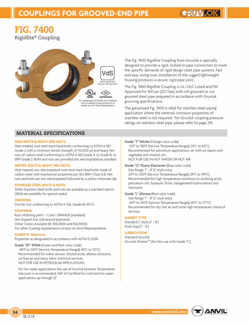
FIG. 7400Rigidlite® Coupling
The Fig. 7400 Rigidlite Coupling from Gruvlok is specially designed to provide a rigid, locked-in pipe connection to meet the specific demands of rigid design steel pipe systems. Fast and easy swing-over installation of the rugged lightweight housing produces a secure, rigid pipe joint.
The Fig. 7400 Rigidlite Coupling is UL/ULC Listed and FM Approved for 300 psi (20.7 bar) with roll grooved or cut grooved steel pipe prepared in accordance with Gruvlok grooving specifications.
The galvanized Fig. 7400 is ideal for stainless steel piping application where the external corrosion properties of stainless steel is not required. For Gruvlok coupling pressure ratings on stainless steel pipe, please refer to page 214.
MATERIAL SPECIFICATIONS
ANSI BOLTS & HEAVY HEX NUTS:Heat treated, oval neck track head bolts conforming to ASTM A 183 Grade 2 with a minimum tensile strength of 110,000 psi and heavy hex nuts of carbon steel conforming to ASTM A 563 Grade A or Grade B, or J995 Grade 2. Bolts and nuts are provided zinc electroplated as standard.
METRIC BOLTS & HEAVY HEX NUTS:Heat treated, zinc electroplated oval-neck track head bolts made of carbon steel with mechanical properties per ISO 898-1 Class 8.8. Hex nuts and bolts are zinc electroplated followed by a yellow chromate dip.
STAINLESS STEEL BOLTS & NUTS:304SS Stainless Steel bolts and nuts are available as a standard option. (316SS are available for special order).
HOUSING:Ductile Iron conforming to ASTM A 536, Grade 65-45-12.
COATINGS:Rust inhibiting paint – Color: ORANGE (standard)Hot Dipped Zinc Galvanized (optional)Other Colors Available (IE: RAL3000 and RAL9000)For other Coating requirements contact an Anvil Representative.
GASKETS: MaterialsProperties as designated in accordance with ASTM D 2000
Grade “EP” EPDM (Green and Red color code)-40°F to 250°F (Service Temperature Range)(-40°C to 121°C)Recommended for water service, diluted acids, alkalies solutions, oil-free air and many other chemical services.NOT FOR USE IN PETROLEUM APPLICATIONS.
For hot water applications the use of Gruvlok Extreme Temperature lubricant is recommended. NSF-61 Certified for cold and hot water applications up through 12".
Grade “T” Nitrile (Orange color code)-20°F to 180°F (Service Temperature Range)(-29°C to 82°C)Recommended for petroleum applications. air with oil vapors and vegetable and mineral oils.NOT FOR USE IN HOT WATER OR HOT AIR
Grade “O” Fluoro-Elastomer (Blue color code)Size Range: 1" - 8" (C style only)20°F to 300°F (Service Temperature Range)(-29°C to 149°C)Recommended for high temperature resistance to oxidizing acids,petroleum oils, hydraulic fluids, halogenated hydrocarbons and lubricants.
Grade “L” Silicone (Red color code)Size Range: 1" - 8" (C style only)-40°F to 350°F (Service Temperature Range)(-40°C to 177°C)Recommended for dry, hot air and some high temperature chemicalservices.
GASKET TYPE:Standard C Style (1" - 8")Flush Gap (1" - 8")
LUBRICATION:Standard GruvlokGruvlok XtremeTM (Do Not use with Grade “L”)
DN 50 and DN 200sizes are VdS approved.
GL-3.14
For Listings/Approval Details and Limitations,visit our website at www.anvilintl.com orcontact an Anvil® Sales Representative.

COUPLINGS FOR GROOVED-END PIPE
www.anvilintl.com 35
Intro
duct
ion
Coup
lings
Outle
tsFi
tting
sVa
lves
&
Acce
ssor
ies
High
Pres
sure
Di-E
lect
ricNi
pple
sPl
ain-
End
Fitti
ngs
HDPE
Coup
lings
Sock
-It®
Fitti
ngs
Stai
nles
sSt
eel M
etho
dRo
ll Gr
oove
rsIn
stal
latio
n&
Ass
embl
ySp
ecia
lCo
atin
gsDe
sign
Serv
ices
Tech
nica
lDa
taM
aste
r For
mat
3 Pa
rt Sp
ecs.
Pict
oria
lIn
dex
CTS
Copp
er
Syst
em
FIG. 7400Rigidlite® Coupling
FIGURE 7400 RIGIDLITE COUPLING
Nominal Size O.D. Max. Wk.
PressureMax. End
Load
Range of Pipe End
Separation
Coupling Dimensions Coupling Bolts Specified Torque § Approx. Wt. Ea.X Y Z Qty. Size Min. Max.
In./DN(mm) In./mm PSI/bar Lbs./kN In./mm In./mm In./mm In./mm In./mm Ft.-Lbs./N-m Lbs./Kg
1 1.315 300 407 0-1⁄32 21⁄4 41⁄2 13⁄4 2 3⁄8 x 21⁄4 30 45 1.225 33.4 20.7 1.81 0-0.79 57 114 44 M10 x 57 40 60 0.5
11⁄4 1.660 300 649 0-1⁄32 25⁄8 43⁄4 13⁄4 2 3⁄8 x 21⁄4 30 45 1.332 42.2 20.7 2.89 0-0.79 67 121 44 M10 x 57 40 60 0.6
11⁄2 1.900 300 851 0-1⁄32 27⁄8 47⁄8 13⁄4 2 3⁄8 x 21⁄4 30 45 1.440 48.3 20.7 3.78 0-0.79 73 124 44 M10 x 57 40 60 0.6
2 2.375 300 1,329 0-1⁄32 31⁄4 51⁄2 13⁄4 2 3⁄8 x 21⁄4 30 45 1.650* 60.3 20.7 5.91 0-0.79 83 140 44 M10 x 57 40 60 0.7
21⁄2 2.875 300 1,948 0-1⁄32 37⁄8 6 13⁄4 2 3⁄8 x 21⁄4 30 45 1.965 73.0 20.7 8.66 0-0.79 98 152 44 M10 x 57 40 60 0.9
3 O.D. 2.996 300 2,115 0-1⁄32 4 5 7⁄8 13⁄4 2 3⁄8 x 21⁄4 30 45 1.9
76.1 76.1 20.7 9.41 0-0.79 102 149 44 M10 x 57 40 60 0.93 3.500 300 2,886 0-1⁄32 41⁄2 63⁄4 13⁄4 2 3⁄8 x 23⁄4 30 45 2.180 88.9 20.7 12.84 0-0.79 114 171 44 M10 x 70 40 60 1.0
4 4.500 300 4,771 0-3⁄32 55⁄8 73⁄4 17⁄8 2 3⁄8 x 23⁄4 30 45 3.1100 114.3 20.7 21.22 0-2.38 143 197 48 M10 x 70 40 60 1.4
51⁄2 O.D. 5.500 300 7,127 0-3⁄32 63⁄4 91⁄4 2 2 1⁄2 x 3 80 100 4.5
139.7 139.7 20.7 31.70 0-2.38 171 235 51 M12 x 76 110 150 2.05 5.563 300 7,292 0-3⁄32 67⁄8 91⁄4 2 2 1⁄2 x 3 80 100 4.6
125 141.3 20.7 32.44 0-2.38 175 235 51 M12 x 76 110 150 2.161⁄2 O.D. 6.500 300 9,955 0-3⁄32 73⁄4 103⁄8 2 2 1⁄2 x 3 80 100 5.5
165.1 165.1 20.7 44.28 0-2.38 200 264 51 M12 x 76 110 150 2.56 6.625 300 10,341 0-3⁄32 77⁄8 103⁄8 2 2 1⁄2 x 3 80 100 5.5
150 168.3 20.7 46.00 0-2.38 200 264 51 M12 x 76 110 150 2.5
8 8.625 300 17,528 0-3⁄32 101⁄4 123⁄4 23⁄8 2 1⁄2 x 3 80 100 8.4200* 219.1 20.7 77.97 0-2.38 260 324 60 M12 x 76 110 150 3.8
YZ
X
GL-6.11
For additional details see “Coupling Data Chart Notes” on page 17.* DN 50 and DN 200 sizes are VdS approved.§ – For additional Bolt Torque information, see page 204.See Installation & Assembly directions on page 170.
NOTE:Range of Pipe End Seperation values are for roll grooved pipe and may be doubled for cut groove pipe.Other sizes available, contact an Anvil Representative for more information.

COUPLINGS FOR GROOVED-END PIPE
www.anvilintl.com36
FIG. 7003Hingelok® Coupling
The Fig. 7003 Hingelok Coupling is specially designed for applications requiring a quick connection and/or disconnection of a pipe joint. The Fig. 7003 Hingelok Coupling is ideal for those applications where frequent pipe removal is required for maintenance or any other reason. Fig. 7003 Hingelok Coupling provides for system working pressure ratings up to 300 psi (20.7 bar).
The Fig. 7003 Hingelok Coupling halves are permanently hinged to provide an assembly that eases handling and installation. The two coupling halves are hinged for ease of handling and are secured by a cam-action handle. Sizes 1" to 4" use toggle link plates and sizes 5" to 8" use a toggle bolt to attach the cam-action handle to the housings. The cam-action locking handle permits rapid installation without the need for additional tools and maintains secure closure of the coupling into the pipe grooves. Final assembly of the locking pin to the Hingelok Coupling adds an extra measure of security required in critical pipe joint applications.
MATERIAL SPECIFICATIONS
HOUSING:Ductile Iron conforming to ASTM A 536, Grade 65-45-12.
COATINGS:Rust inhibiting paint Color: ORANGE (standard)Hot Dipped Zinc Galvanized (optional)Other Colors Available (IE: RAL3000 and RAL9000)For other Coating requirements contact an Anvil Representative.
HANDLE:Sizes 1" - 4": Cold Rolled Carbon Steel HandlesSizes 5” - 8": Cast Ductile Iron Handles
LINKS:Sizes 1" - 4": Cold Rolled Carbon Steel LinksSizes 5" - 8": Heat Treated Steel Links
LOCKING PIN:Locking Pin: Spring Steel
GASKETS: MaterialsProperties as designated in accordance with ASTM D 2000
Grade “EP” EPDM (Green and Red color code)-40°F to 250°F (Service Temperature Range)(-40°C to 121°C)Recommended for water service, diluted acids, alkalies solutions, oil-free air and many other chemical services.NOT FOR USE IN PETROLEUM APPLICATIONS.
For hot water applications the use of Gruvlok Extreme Temperature lubricant is recommended. NSF-61 Certified for cold and hot water applications up through 12".
Grade “E” EPDM (Green color code)-40°F to 230°F (Service Temperature Range)(-40°C to 110°C)Recommended for water service, diluted acids, alkalies solutions, oil-free air and many other chemical services.NOT FOR USE IN PETROLEUM APPLICATIONS.
Grade “T” Nitrile (Orange color code)-20°F to 180°F (Service Temperature Range)(-29°C to 82°C)Recommended for petroleum applications. air with oil vapors andvegetable and mineral oils.NOT FOR USE IN HOT WATER OR HOT AIR.
Grade “O” Fluoro-Elastomer (Blue color code)Size Range: 1" - 8" (C style only)20°F to 300°F (Service Temperature Range)(-29°C to 149°C)Recommended for high temperature resistance to oxidizing acids,petroleum oils, hydraulic fluids, halogenated hydrocarbons and lubricants.
Grade “L” Silicone (Red color code)Size Range: 1" - 8" (C style only)-40°F to 350°F (Service Temperature Range)(-40°C to 177°C)Recommended for dry, hot air and some high temperature chemicalservices. DO NOT USE GRUVLOK XTREME LUBRICANT WITH GRADE “L” SILICONE GASKET.
GASKET TYPE:Standard C Style (1" - 8")Flush Gap (1" - 8")
LUBRICATION:Standard GruvlokGruvlok XtremeTM (Do Not use with Grade “L”)
SIZES 1" - 4"
SIZES 5" - 8"
GL-3.14

COUPLINGS FOR GROOVED-END PIPE
www.anvilintl.com 37
Intro
duct
ion
Coup
lings
Outle
tsFi
tting
sVa
lves
&
Acce
ssor
ies
High
Pres
sure
Di-E
lect
ricNi
pple
sPl
ain-
End
Fitti
ngs
HDPE
Coup
lings
Sock
-It®
Fitti
ngs
Stai
nles
sSt
eel M
etho
dRo
ll Gr
oove
rsIn
stal
latio
n&
Ass
embl
ySp
ecia
lCo
atin
gsDe
sign
Serv
ices
Tech
nica
lDa
taM
aste
r For
mat
3 Pa
rt Sp
ecs.
Pict
oria
lIn
dex
CTS
Copp
er
Syst
em
FIG. 7003Hingelok® Coupling
FIGURE 7003 HINGELOK COUPLING
Nominal Size O.D. Max. Wk.
PressureMax. End
LoadRange of Pipe End
Separation
Deflection from CL Coupling Dimensions Approx. Wt. Ea.Per Coupling of Pipe X Y Z
In./DN(mm) In./mm PSI/bar Lbs./kN In./mm Degrees(˚)-Minutes(') In./ft-mm/m In./mm In./mm In./mm Lbs./Kg
1* 1.315 300 407 0-1⁄32 1° 22' 0.29 3 4 13⁄4 1.425 33.4 20.7 1.81 0-0.79 23.8 76 101 44 0.6
11⁄4* 1.660 300 649 0-1⁄32 1° 5' 0.23 37⁄16 47⁄16 17⁄8 1.532 42.2 20.7 2.89 0-0.79 18.8 87 113 48 0.7
11⁄2 1.900 300 851 0-1⁄32 0° 57' 0.20 35⁄8 41⁄4 17⁄8 1.740 48.3 20.7 3.78 0-0.79 16.5 92 108 48 0.8
2 2.375 300 1,329 0-1⁄32 0° 45' 0.16 41⁄4 47⁄8 17⁄8 2.250 60.3 20.7 5.91 0-0.79 13.1 108 124 48 1.0
21⁄2 2.875 300 1,948 0-1⁄32 0° 37' 0.13 51⁄4 57⁄8 17⁄8 3.265 73.0 20.7 8.66 0-0.79 10.9 133 149 48 1.5
3 3.500 300 2,886 0-1⁄32 0° 31' 0.11 55⁄8 61⁄2 17⁄8 3.680 88.9 20.7 12.84 0-0.79 8.9 143 165 48 1.6
4 4.500 300 4,771 0-3⁄32 1° 12' 0.25 7 73⁄4 2 5.1100 114.3 20.7 21.22 0-2.38 20.8 178 197 51 2.3
5 5.563 300 7,292 0-3⁄32 0° 58' 0.20 85⁄8 91⁄2 21⁄8 9.5125 141.3 20.7 32.44 0-2.38 16.8 219 241 54 4.3
6 6.625 300 10,341 0-3⁄32 0° 49' 0.17 97⁄8 107⁄8 21⁄8 11.2150 168.3 20.7 46.00 0-2.38 14.14 251 276 54 5.1
8 8.625 300 17,528 0-3⁄32 0° 37' 0.13 12 131⁄8 21⁄2 18.1200 219.1 20.7 77.97 0-2.38 10.9 305 333 64 8.2
Y
X
Z
GL-3.14
For additional details see “Coupling Data Chart Notes” on page 17.See Installation & Assembly directions on page 174.Not for use in copper systems.
NOTES:* 1" and 11/4" are import products.Range of Pipe End Separation and Angular Deflection values are for roll grooved pipe and may be doubled for cut groove pipe. See page 204 for details. Refer to page 210 for Misalignment & Deflection Calculations and page 211 for Curve Layout Calculations.
SPECIAL NOTE:Fig. 7003 Hingelok Couplings are not designed for eccentric loading and therefore are not recommended for use at the end of concrete pumping booms or vertical risers above 30 feet (9.1 meters). Shockload must be considered and is to be included in the maximum working pressure listed above. Coupling keys, gasket cavity, and pipe grooves must be kept free of all foreign matter. Proper anchoring practice must always be exercised.
CAUTION:Hammering or banging on the handle or coupling housing could cause serious damage to the locking device and coupling assembly. The result may be an unsuitable pipe joint and unusable coupling assembly.When re-using, always check for gasket damage, housing hinge and handle for looseness, distortion, bending or any other damage.

COUPLINGS FOR GROOVED-END PIPE
www.anvilintl.com38
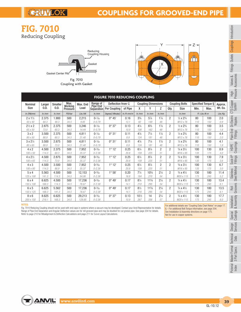
FIG. 7010Reducing Coupling
The Fig. 7010 Reducing Coupling makes it possible to directly connect two different pipe sizes, eliminating the need for two couplings and a reducing fitting. The specially designed reducing coupling gasket with a center rib assures proper positioning of the gasket and prevents the smaller pipe from telescoping into the larger during assembly. Fig. 7010 Reducing Coupling allows for working pressure ratings up to 500 PSI (34.5 bar). Not recommended for vacuum applications.
MATERIAL SPECIFICATIONS
ANSI BOLTS & HEAVY HEX NUTS:Heat treated, oval neck track head bolts conforming to ASTM A 183 Grade 2 with a minimum tensile strength of 110,000 psi and heavy hex nuts of carbon steel conforming to ASTM A 563 Grade A or Grade B, or J995 Grade 2. Bolts and nuts are provided zinc electroplated as standard.
METRIC BOLTS & HEAVY HEX NUTS:Heat treated, zinc electroplated oval-neck track head bolts made of carbon steel with mechanical properties per ISO 898-1 Class 8.8. Hex nuts are zinc electroplated followed by a yellow chromate dip.
HOUSING:Ductile Iron conforming to ASTM A 536, Grade 65-45-12, orMalleable Iron conforming to ASTM A 47, Grade 32510.
COATINGS:Rust inhibiting paint – Color: ORANGE (standard)Hot Dipped Zinc Galvanized (optional)Other Colors Available (IE: RAL3000 and RAL9000)For other Coating requirements contact an Anvil Representative.
GASKETS: MaterialsProperties as designated in accordance with ASTM D 2000
Grade “E” EPDM (Green color code)-40°F to 230°F (Service Temperature Range)(-40°C to 110°C)Recommended for water service, diluted acids, alkalies solutions, oil-free air and many other chemical services.NOT FOR USE IN PETROLEUM APPLICATIONS.
Grade “T” Nitrile (Orange color code)-20°F to 180°F (Service Temperature Range)(-29°C to 82°C)Recommended for petroleum applications. air with oil vapors andvegetable and mineral oils.NOT FOR USE IN HOT WATER OR HOT AIR.
LUBRICATION:Standard GruvlokGruvlok XtremeTM (Do Not use with Grade “L”)
GL-3.14
For Listings/Approval Details and Limitations,visit our website at www.anvilintl.com orcontact an Anvil® Sales Representative.
COUPLINGS FOR GROOVED-END PIPE
www.anvilintl.com 39
Intro
duct
ion
Coup
lings
Outle
tsFi
tting
sVa
lves
&
Acce
ssor
ies
High
Pres
sure
Di-E
lect
ricNi
pple
sPl
ain-
End
Fitti
ngs
HDPE
Coup
lings
Sock
-It®
Fitti
ngs
Stai
nles
sSt
eel M
etho
dRo
ll Gr
oove
rsIn
stal
latio
n&
Ass
embl
ySp
ecia
lCo
atin
gsDe
sign
Serv
ices
Tech
nica
lDa
taM
aste
r For
mat
3 Pa
rt Sp
ecs.
Pict
oria
lIn
dex
CTS
Copp
er
Syst
em
FIG. 7010Reducing Coupling
FIGURE 7010 REDUCING COUPLING
Nominal Size
Larger O.D.
Smaller O.D.
Max. Working Pressure
Max. End Load
Range of Pipe End
Separation
Deflection from CL Coupling Dimensions Coupling Bolts Specified Torque § Approx. Wt. Ea.Per Coupling of Pipe X Y Z Qty. Size Min. Max.
In./DN(mm) In./mm In./mm PSI/bar Lbs./kN In./mm Degrees(˚)-Minutes(') In./ft-mm/m In./mm In./mm In./mm In./mm Ft.-Lbs./N-m Lbs./Kg
2 x 11⁄2 2.375 1.900 500 2,215 0-1⁄32 0° 45' 0.16 35⁄8 57⁄8 17⁄8 2 1⁄2 x 23⁄4 80 100 2.050 x 40 60.3 48.3 34.5 9.85 0-0.79 13.1 92 149 48 M12 x 76 110 150 0.9
21⁄2 x 2 2.875 2.375 500 3,246 0-1⁄32 0° 37' 0.13 41⁄4 63⁄8 17⁄8 2 1⁄2 x 23⁄4 80 100 3.565 x 50 73.0 60.3 34.5 14.44 0-0.79 10.9 108 162 48 M12 x 76 110 150 1.6
3 x 2 3.500 2.375 500 4,811 0-1⁄32 0° 31' 0.11 47⁄8 71⁄8 17⁄8 2 1⁄2 x 23⁄4 80 100 4.480 x 50 88.9 60.3 34.5 21.40 0-0.79 8.9 124 181 48 M12 x 76 110 150 2.0
3 x 21⁄2 3.500 2.875 500 4,811 0-1⁄32 0° 31' 0.11 47⁄8 71⁄8 17⁄8 2 1⁄2 x 23⁄4 80 100 4.180 x 65 88.9 73.0 34.5 21.40 0-0.79 8.9 124 181 48 M12 x 76 110 150 1.9
4 x 2 4.500 2.375 500 7,952 0-3⁄32 1° 12' 0.25 61⁄4 87⁄8 2 2 5⁄8 x 31⁄2 100 130 8.9100 x 50 114.3 60.3 34.5 35.37 0-2.38 20.8 159 225 51 M16 x 95 135 175 4.0
4 x 21⁄2 4.500 2.875 500 7,952 0-3⁄32 1° 12' 0.25 61⁄4 87⁄8 2 2 5⁄8 x 31⁄2 100 130 7.9100 x 65 114.3 73.0 34.5 35.37 0-2.38 20.8 159 225 51 M16 x 95 135 175 3.6
4 x 3 4.500 3.500 500 7,952 0-3⁄32 1° 12' 0.25 61⁄4 87⁄8 2 2 5⁄8 x 31⁄2 100 130 6.7100 x 80 114.3 88.9 34.5 35.37 0-2.38 20.8 159 225 51 M16 x 95 135 175 3.0
5 x 4 5.563 4.500 500 12,153 0-3⁄32 1° 58' 0.20 71⁄4 105⁄8 21⁄8 2 3⁄4 x 41⁄2 130 180 11.4125 x 100 141.3 114.3 34.5 54.06 0-2.38 16.8 184 270 54 M20 x 115 175 245 5.2
6 x 4 6.625 4.500 500 17,236 0-3⁄32 0° 49' 0.17 81⁄4 115⁄8 21⁄8 2 3⁄4 x 41⁄2 130 180 13.4150 x 100 168.3 114.3 34.5 76.67 0-2.38 14.1 210 295 54 M20 x 115 175 245 6.1
6 x 5 6.625 5.562 500 17,236 0-3⁄32 0° 49' 0.17 81⁄2 115⁄8 21⁄8 2 3⁄4 x 41⁄2 130 180 13.5150 x 125 168.3 141.3 34.5 76.67 0-2.38 14.1 216 295 54 M20 x 115 175 245 6.1
8 x 6 8.625 6.625 500 29,213 0-3⁄32 0° 37' 0.13 101⁄2 14 21⁄4 2 3⁄4 x 41⁄2 130 180 17.7200 x 150 219.1 168.3 34.5 129.95 0-2.38 10.9 267 356 57 M20 x 115 175 245 8.0
Fig. 7010Coupling with Gasket
GL-10.12
NOTES:Fig. 7010 Reducing Coupling should not be used with end caps in systems where a vacuum may be developed. Contact your Anvil Representative for details.Range of Pipe End Separation and Angular Deflection values are for roll grooved pipe and may be doubled for cut groove pipe. See page 204 for details. Refer to page 210 for Misalignment & Deflection Calculations and page 211 for Curve Layout Calculations.
For additional details see “Coupling Data Chart Notes” on page 17.§ – For additional Bolt Torque information, see page 204.See Installation & Assembly directions on page 175.Not for use in copper systems.