GRP Manholes and Chambers - subor.com.tr · GRP manholes and chambers are made of FLOWTITE GRP...
20
GRP Manholes and Chambers for Gravity and Pressure Applications
Transcript of GRP Manholes and Chambers - subor.com.tr · GRP manholes and chambers are made of FLOWTITE GRP...
GRP Manholes and Chambersfor Gravity and Pressure Applications
2
Table of contents
1 GRP Manholes and Chambers .....................................................................................................................31.1 General Information ............................................................................................................................ 31.2 Purpose .............................................................................................................................................. 31.3 Quality Standards ............................................................................................................................... 31.4 Features & Benefits ............................................................................................................................ 3 1.5 Types of GRP Manholes and Chambers ............................................................................................ 4
2 Manholes for Gravity Applications for Storm & Waste Water ...................................................................62.1 Cylindrical Manholes .......................................................................................................................... 62.2 Tangential Manholes ........................................................................................................................... 72.3 Special Manholes ............................................................................................................................... 82.4 Inlet Drain Pits .................................................................................................................................... 82.5 Separate Systems for Storm and Waste Water ................................................................................. 9 2.6 Double-wall Solutions for Protected Areas ........................................................................................ 9
3 Manholes and Chambers in Pressure Systems .......................................................................................103.1 Inspection Chambers ....................................................................................................................... 103.2 Manholes and Chambers for Pumping Stations .............................................................................. 10
4 Equipment and Components of Manholes and Chambers .....................................................................124.1 Manhole/Chambers Tops ................................................................................................................. 124.1.1 Load-transmitting Capping Structures ............................................................................................. 124.1.2 Unload-transmitting Capping Structures ......................................................................................... 124.1.3 Konus Capping Structures ............................................................................................................... 13 4.2 Manhole Foundations ....................................................................................................................... 134.3 Connections to other Pipe Materials ............................................................................................... 144.4 Ladders, Steps and Benching .......................................................................................................... 144.5 Backdrop Solutions (Cascades) ....................................................................................................... 15 Appendix A - Order form for drain/ sewage GRP manholes .......................................................................................16Appendix B - Order form for tangential manhole with berm .......................................................................................17Appendix C - Order form for tangential manhole without berm ..................................................................................18Appendix D - Order form for a manhole as a pump housing ......................................................................................19

3
1 GRP Manholes and Chambers
1.1 General Information
GRP manholes and chambers are made of FLOWTITE GRP pipes as integral part of pipe installations. Their design is based on FLOWTITE GRP pipes and GRP plates, joined together with the use of polyester - glass fibre laminates. The technology used in the production process of GRP manholes and chambers guarantees that they are completely sealed, fully corrosion proof, have excellent durability and can be safely serviced and maintained. Manholes and chambers are monolithic products with defined composition and properties.
1.2 Purpose
Manholes and chambers form a part of underground gravitational and pressure systems, allowing for the inspection and operation of pipelines and fittings, as well as for changing the flow conditions of a medium, within the range of their intended use.
GRP manholes and chambers are primarily designed to be used for:
inspection and maintenance of drains or sewers ventilation of drains or sewers flow conditions change of a medium
(change of direction, change of pressure, change of water flow rate)
cleaning and flushing of drains or sewers maintenance of water meters and fittings housing of pumping stations inlet drain pits
1.3 Quality Standards
All AMITECH entities that manufacture manholes and chambers are certified according to ISO 9001 and other international and national production standards. During the production of the basic GRP elements, frequent checks are made on the flow of raw materials, machine speed and winder adjustments.
Design and laminate specification of each manhole is permanently controlled to meet the requirements and standards of the customer’s specifications.
The raw material components are periodically controlled with regard to quality, consistence and their physical/ chemical properties. The finished manholes and chambers meet the demands of prEN 15383 and the requirements on tightness according to EN 1610 after installation.
1.4 Features & Benefits
FLOWTITE GRP manholes consist of a composition of high tech materials and offer many features and benefits:
Non-corrosive Durable Safe Maintenance-free Internal and external corrosion resistance
One-piece wall structure Restricts infiltration Avoids exfiltration
Lightweight Easy handling Unloading with light equipment No heavy equipment necessary for installation
Easy installation Savings in installation time Smaller excavation No heavy footings No waiting time for curing of the base plate before
installation Easy fabrication: additional pipe entries can be cut
with standard power tools No assembling on site Minor grouting necessary Easy inspection
Reliable product Dependable Dimensionally stable Uniform design

4
1.5 Types of GRP Manholes and Chambers
Depending on the maintenance tasks, drain/sewer GRP manholes and chambers can be divided into two types:
accessible manholes – they allow for entering and exiting in order to carry out maintenance tasks. The manhole has a ladder fixed with bolts to the wall of the manhole funnel. The diameter of the manhole funnel is bigger than/equal to DN≥1000.
non accessible (inspection chambers) – they allow for carrying out maintenance tasks from street level using suitable equipment. The diameter of the manhole unit is smaller than DN<1000.
! Note: The use, execution and availability of the different manhole types depend on local regulations which might differ from country to country. For detailed information please contact your local distributor.
AMITECH GRPmanholes and chambers
Manholes and chambers for pressure applications
Tangential GRP manholes
with bench plate
without bench plate
Eccentric Centric
Cylindrical GRP manholes
with bottom plate
without bottom plate
Non-circular profile manholes
Manholes for double wall pipe system
Energy dissipater manholes
Pump houses
Valve chambers
Inspection chambers for pressure equipment
Manholes for special applications (storm & waste water)
Manholes for gravity applications
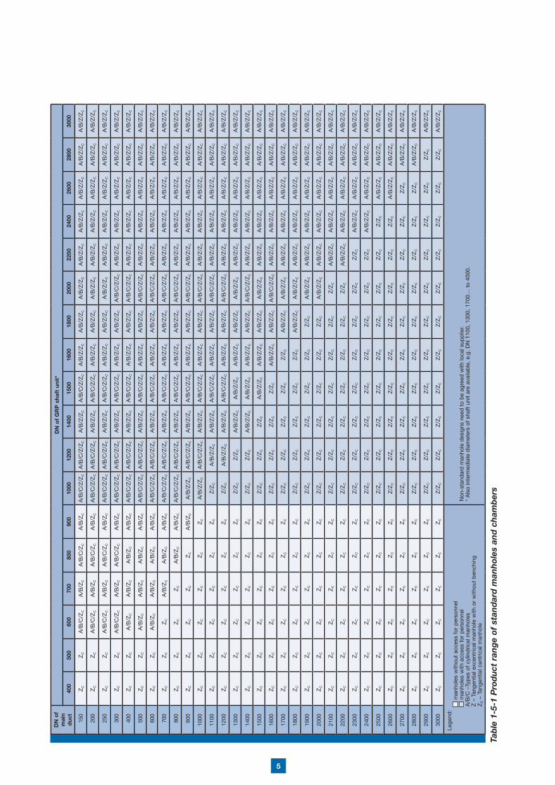
5
Tab
le 1
-5-1
Pro
du
ct r
ang
e of
sta
nd
ard
man
hol
es a
nd
ch
amb
ers
DN
of
mai
n d
uct
DN
of
GR
P s
haft
uni
t*
400
500
600
700
800
900
1000
1200
1400
1500
1600
1800
2000
2200
2400
2600
2800
3000
150
ZC
ZC
A/B
/C/Z
CA
/B/Z
CA
/B/C
/ZC
A/B
/ZC
A/B
/C/Z
/ZC
A/B
/C/Z
/ZC
A/B
/Z/Z
CA
/B/C
/Z/Z
CA
/B/Z
/ZC
A/B
/Z/Z
CA
/B/Z
/ZC
A/B
/Z/Z
CA
/B/Z
/ZC
A/B
/Z/Z
CA
/B/Z
/ZC
A/B
/Z/Z
C
200
ZC
ZC
A/B
/C/Z
CA
/B/Z
CA
/B/C
/ZC
A/B
/ZC
A/B
/C/Z
/ZC
A/B
/C/Z
/ZC
A/B
/Z/Z
CA
/B/C
/Z/Z
CA
/B/Z
/ZC
A/B
/Z/Z
CA
/B/Z
/ZC
A/B
/Z/Z
CA
/B/Z
/ZC
A/B
/Z/Z
CA
/B/Z
/ZC
A/B
/Z/Z
C
250
ZC
ZC
A/B
/C/Z
CA
/B/Z
CA
/B/C
/ZC
A/B
/ZC
A/B
/C/Z
/ZC
A/B
/C/Z
/ZC
A/B
/Z/Z
CA
/B/C
/Z/Z
CA
/B/Z
/ZC
A/B
/Z/Z
CA
/B/Z
/ZC
A/B
/Z/Z
CA
/B/Z
/ZC
A/B
/Z/Z
CA
/B/Z
/ZC
A/B
/Z/Z
C
300
ZC
ZC
A/B
/C/Z
CA
/B/Z
CA
/B/C
/ZC
A/B
/ZC
A/B
/C/Z
/ZC
A/B
/C/Z
/ZC
A/B
/Z/Z
CA
/B/C
/Z/Z
CA
/B/Z
/ZC
A/B
/Z/Z
CA
/B/C
/Z/Z
CA
/B/Z
/ZC
A/B
/Z/Z
CA
/B/Z
/ZC
A/B
/Z/Z
CA
/B/Z
/ZC
400
ZC
ZC
A/B
/ZC
A/B
/ZC
A/B
/ZC
A/B
/ZC
A/B
/C/Z
/ZC
A/B
/C/Z
/ZC
A/B
/Z/Z
CA
/B/C
/Z/Z
CA
/B/Z
/ZC
A/B
/Z/Z
CA
/B/C
/Z/Z
CA
/B/Z
/ZC
A/B
/Z/Z
CA
/B/Z
/ZC
A/B
/Z/Z
CA
/B/Z
/ZC
500
ZC
ZC
A/B
/ZC
A/B
/ZC
A/B
/ZC
A/B
/ZC
A/B
/C/Z
/ZC
A/B
/C/Z
/ZC
A/B
/Z/Z
CA
/B/C
/Z/Z
CA
/B/Z
/ZC
A/B
/Z/Z
CA
/B/C
/Z/Z
CA
/B/Z
/ZC
A/B
/Z/Z
CA
/B/Z
/ZC
A/B
/Z/Z
CA
/B/Z
/ZC
600
ZC
ZC
A/B
/ZC
A/B
/ZC
A/B
/ZC
A/B
/ZC
A/B
/C/Z
/ZC
A/B
/C/Z
/ZC
A/B
/Z/Z
CA
/B/C
/Z/Z
CA
/B/Z
/ZC
A/B
/Z/Z
CA
/B/C
/Z/Z
CA
/B/Z
/ZC
A/B
/Z/Z
CA
/B/Z
/ZC
A/B
/Z/Z
CA
/B/Z
/ZC
700
ZC
ZC
ZC
A/B
/ZC
A/B
/ZC
A/B
/ZC
A/B
/C/Z
/ZC
A/B
/C/Z
/ZC
A/B
/Z/Z
CA
/B/C
/Z/Z
CA
/B/Z
/ZC
A/B
/Z/Z
CA
/B/C
/Z/Z
CA
/B/Z
/ZC
A/B
/Z/Z
CA
/B/Z
/ZC
A/B
/Z/Z
CA
/B/Z
/ZC
800
ZC
ZC
ZC
ZC
A/B
/ZC
A/B
/ZC
A/B
/C/Z
/ZC
A/B
/C/Z
/ZC
A/B
/Z/Z
CA
/B/C
/Z/Z
CA
/B/Z
/ZC
A/B
/Z/Z
CA
/B/C
/Z/Z
CA
/B/Z
/ZC
A/B
/Z/Z
CA
/B/Z
/ZC
A/B
/Z/Z
CA
/B/Z
/ZC
900
ZC
ZC
ZC
ZC
ZC
A/B
/ZC
A/B
/Z/Z
CA
/B/C
/Z/Z
CA
/B/Z
/ZC
A/B
/C/Z
/ZC
A/B
/Z/Z
CA
/B/Z
/ZC
A/B
/C/Z
/ZC
A/B
/Z/Z
CA
/B/Z
/ZC
A/B
/Z/Z
CA
/B/Z
/ZC
A/B
/Z/Z
C
1000
ZC
ZC
ZC
ZC
ZC
ZC
A/B
/Z/Z
CA
/B/C
/Z/Z
CA
/B/Z
/ZC
A/B
/C/Z
/ZC
A/B
/Z/Z
CA
/B/Z
/ZC
A/B
/C/Z
/ZC
A/B
/Z/Z
CA
/B/Z
/ZC
A/B
/Z/Z
CA
/B/Z
/ZC
A/B
/Z/Z
C
1100
ZC
ZC
ZC
ZC
ZC
ZC
Z/Z
CA
/B/Z
/ZC
A/B
/Z/Z
CA
/B/C
/Z/Z
CA
/B/Z
/ZC
A/B
/Z/Z
CA
/B/C
/Z/Z
CA
/B/Z
/ZC
A/B
/Z/Z
CA
/B/Z
/ZC
A/B
/Z/Z
CA
/B/Z
/ZC
1200
ZC
ZC
ZC
ZC
ZC
ZC
Z/Z
CA
/B/Z
/ZC
A/B
/Z/Z
CA
/B/C
/Z/Z
CA
/B/Z
/ZC
A/B
/Z/Z
CA
/B/C
/Z/Z
CA
/B/Z
/ZC
A/B
/Z/Z
CA
/B/Z
/ZC
A/B
/Z/Z
CA
/B/Z
/ZC
1300
ZC
ZC
ZC
ZC
ZC
ZC
Z/Z
CZ
/ZC
A/B
/Z/Z
CA
/B/Z
/ZC
A/B
/Z/Z
CA
/B/Z
/ZC
A/B
/Z/Z
CA
/B/Z
/ZC
A/B
/Z/Z
CA
/B/Z
/ZC
A/B
/Z/Z
CA
/B/Z
/ZC
1400
ZC
ZC
ZC
ZC
ZC
ZC
Z/Z
CZ
/ZC
A/B
/Z/Z
CA
/B/Z
/ZC
A/B
/Z/Z
CA
/B/Z
/ZC
A/B
/C/Z
/ZC
A/B
/Z/Z
CA
/B/Z
/ZC
A/B
/Z/Z
CA
/B/Z
/ZC
A/B
/Z/Z
C
1500
ZC
ZC
ZC
ZC
ZC
ZC
Z/Z
CZ
/ZC
Z/Z
CA
/B/Z
/ZC
A/B
/Z/Z
CA
/B/Z
/ZC
A/B
/Z/Z
CA
/B/Z
/ZC
A/B
/Z/Z
CA
/B/Z
/ZC
A/B
/Z/Z
CA
/B/Z
/ZC
1600
ZC
ZC
ZC
ZC
ZC
ZC
Z/Z
CZ
/ZC
Z/Z
CZ
/ZC
A/B
/Z/Z
CA
/B/Z
/ZC
A/B
/C/Z
/ZC
A/B
/Z/Z
CA
/B/Z
/ZC
A/B
/Z/Z
CA
/B/Z
/ZC
A/B
/Z/Z
C
1700
ZC
ZC
ZC
ZC
ZC
ZC
Z/Z
CZ
/ZC
Z/Z
CZ
/ZC
Z/Z
CA
/B/Z
/ZC
A/B
/Z/Z
CA
/B/Z
/ZC
A/B
/Z/Z
CA
/B/Z
/ZC
A/B
/Z/Z
CA
/B/Z
/ZC
1800
ZC
ZC
ZC
ZC
ZC
ZC
Z/Z
CZ
/ZC
Z/Z
CZ
/ZC
Z/Z
CA
/B/Z
/ZC
A/B
/Z/Z
CA
/B/Z
/ZC
A/B
/Z/Z
CA
/B/Z
/ZC
A/B
/Z/Z
CA
/B/Z
/ZC
1900
ZC
ZC
ZC
ZC
ZC
ZC
Z/Z
CZ
/ZC
Z/Z
CZ
/ZC
Z/Z
CZ
/ZC
A/B
/Z/Z
CA
/B/Z
/ZC
A/B
/Z/Z
CA
/B/Z
/ZC
A/B
/Z/Z
CA
/B/Z
/ZC
2000
ZC
ZC
ZC
ZC
ZC
ZC
Z/Z
CZ
/ZC
Z/Z
CZ
/ZC
Z/Z
CZ
/ZC
A/B
/Z/Z
CA
/B/Z
/ZC
A/B
/Z/Z
CA
/B/Z
/ZC
A/B
/Z/Z
CA
/B/Z
/ZC
2100
ZC
ZC
ZC
ZC
ZC
ZC
Z/Z
CZ
/ZC
Z/Z
CZ
/ZC
Z/Z
CZ
/ZC
Z/Z
CA
/B/Z
/ZC
A/B
/Z/Z
CA
/B/Z
/ZC
A/B
/Z/Z
CA
/B/Z
/ZC
2200
ZC
ZC
ZC
ZC
ZC
ZC
Z/Z
CZ
/ZC
Z/Z
CZ
/ZC
Z/Z
CZ
/ZC
Z/Z
CA
/B/Z
/ZC
A/B
/Z/Z
CA
/B/Z
/ZC
A/B
/Z/Z
CA
/B/Z
/ZC
2300
ZC
ZC
ZC
ZC
ZC
ZC
Z/Z
CZ
/ZC
Z/Z
CZ
/ZC
Z/Z
CZ
/ZC
Z/Z
CZ
/ZC
A/B
/Z/Z
CA
/B/Z
/ZC
A/B
/Z/Z
CA
/B/Z
/ZC
2400
ZC
ZC
ZC
ZC
ZC
ZC
Z/Z
CZ
/ZC
Z/Z
CZ
/ZC
Z/Z
CZ
/ZC
Z/Z
CZ
/ZC
A/B
/Z/Z
CA
/B/Z
/ZC
A/B
/Z/Z
CA
/B/Z
/ZC
2500
ZC
ZC
ZC
ZC
ZC
ZC
Z/Z
CZ
/ZC
Z/Z
CZ
/ZC
Z/Z
CZ
/ZC
Z/Z
CZ
/ZC
Z/Z
CA
/B/Z
/ZC
A/B
/Z/Z
CA
/B/Z
/ZC
2600
ZC
ZC
ZC
ZC
ZC
ZC
Z/Z
CZ
/ZC
Z/Z
CZ
/ZC
Z/Z
CZ
/ZC
Z/Z
CZ
/ZC
Z/Z
CA
/B/Z
/ZC
A/B
/Z/Z
CA
/B/Z
/ZC
2700
ZC
ZC
ZC
ZC
ZC
ZC
Z/Z
CZ
/ZC
Z/Z
CZ
/ZC
Z/Z
CZ
/ZC
Z/Z
CZ
/ZC
Z/Z
CZ
/ZC
A/B
/Z/Z
CA
/B/Z
/ZC
2800
ZC
ZC
ZC
ZC
ZC
ZC
Z/Z
CZ
/ZC
Z/Z
CZ
/ZC
Z/Z
CZ
/ZC
Z/Z
CZ
/ZC
Z/Z
CZ
/ZC
A/B
/Z/Z
CA
/B/Z
/ZC
2900
ZC
ZC
ZC
ZC
ZC
ZC
Z/Z
CZ
/ZC
Z/Z
CZ
/ZC
Z/Z
CZ
/ZC
Z/Z
CZ
/ZC
Z/Z
CZ
/ZC
Z/Z
CA
/B/Z
/ZC
3000
ZC
ZC
ZC
ZC
ZC
ZC
Z/Z
CZ
/ZC
Z/Z
CZ
/ZC
Z/Z
CZ
/ZC
Z/Z
CZ
/ZC
Z/Z
CZ
/ZC
Z/Z
CA
/B/Z
/ZC
Lege
nd:
m
anho
les
with
out
acce
ss f
or p
erso
nnel
man
hole
s w
ith a
cces
s fo
r p
erso
nnel
A
/B/C
–Ty
pes
of
cylin
dric
al m
anho
les
Z
– T
ange
ntia
l exc
entr
ical
man
hole
with
or
with
out
ben
chin
g
ZC –
Tan
gent
ial c
entr
ical
man
hole
Non
-sta
ndar
d m
anho
le d
esig
ns n
eed
to
be
agre
ed w
ith lo
cal s
upp
lier.
* A
lso
inte
rmed
iate
dia
met
ers
of s
haft
uni
t ar
e av
aila
ble
, e.
g. D
N 1
100,
130
0, 1
700…
to
4000
.
6
Manholes for gravity applications exist in various models and applications. They are available with different tops in GRP and concrete (see Chapter 4.1 ) and bottoms. On request they can be delivered in one piece, or the GRP shaft can be supplied separately and connected to the concrete base plate on site with a coupling or by lamination. The base plate can be delivered with or without a drainage channel, uncoated or GRP coated for a tight, seamless shaft system. In addition to the main duct, additional inlets are possible, for example stub pipes to connect the manhole with channels made from GRP, PE, PVC, PP, concrete, stoneware, steel and other materials that are used to construct drain/sewer systems. (see Chapter 4.3 ). GRP manholes offer wide flexibility and allow tailor-made designs to customer requests. Please ask your local dealer for availability and details.
2.1 Cylindrical Manholes
This type of manhole is mainly divided into two types:
Cylindrical manhole without uplift protection
This type consists of a GRP FLOWTITE pipe with a shaft unit and a base unit as a foundation of the manhole, inside which the main flow and inlets/outlets
2 Manholes for Gravity Applications for Storm & Waste Water
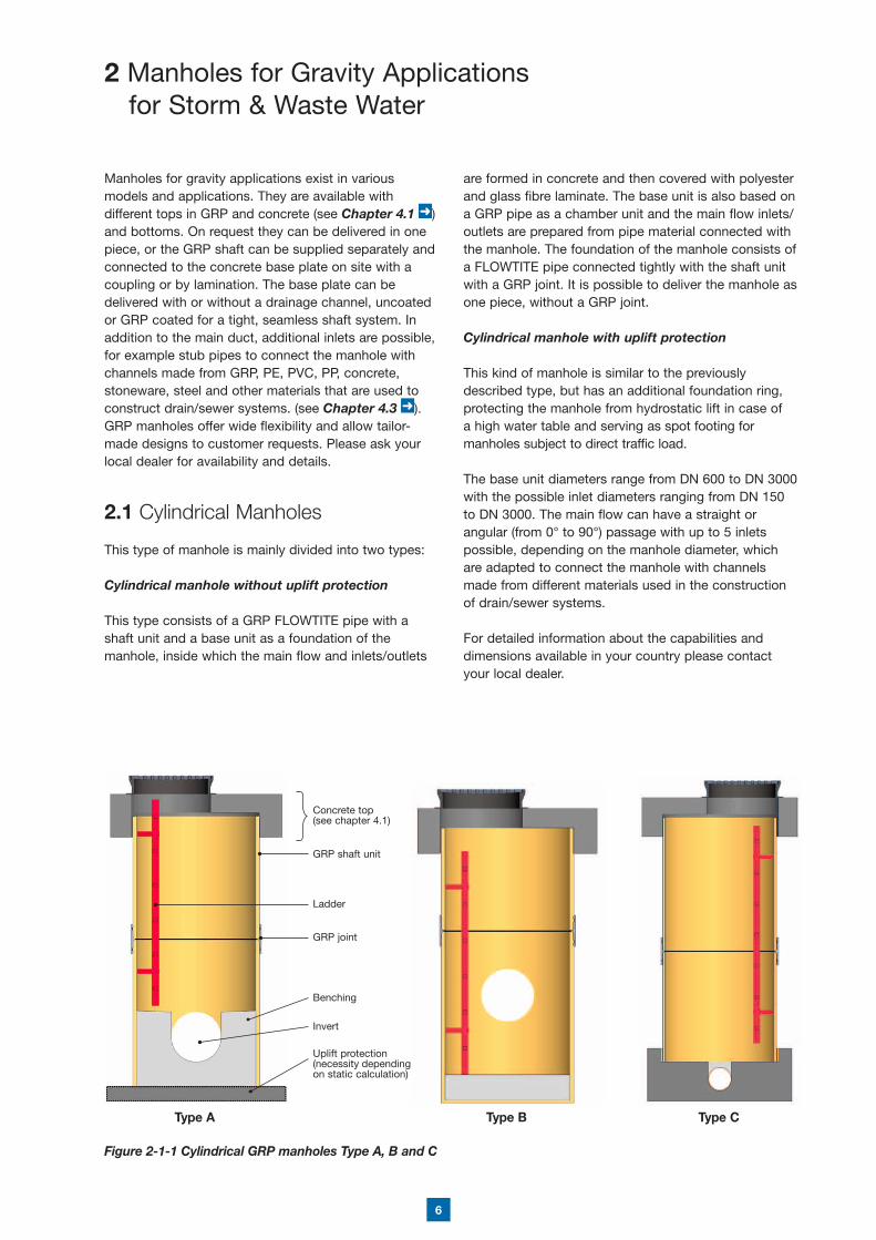
Figure 2-1-1 Cylindrical GRP manholes Type A, B and C
are formed in concrete and then covered with polyester and glass fibre laminate. The base unit is also based on a GRP pipe as a chamber unit and the main flow inlets/outlets are prepared from pipe material connected with the manhole. The foundation of the manhole consists of a FLOWTITE pipe connected tightly with the shaft unit with a GRP joint. It is possible to deliver the manhole as one piece, without a GRP joint.
Cylindrical manhole with uplift protection
This kind of manhole is similar to the previously described type, but has an additional foundation ring, protecting the manhole from hydrostatic lift in case of a high water table and serving as spot footing for manholes subject to direct traffic load.
The base unit diameters range from DN 600 to DN 3000 with the possible inlet diameters ranging from DN 150 to DN 3000. The main flow can have a straight or angular (from 0° to 90°) passage with up to 5 inlets possible, depending on the manhole diameter, which are adapted to connect the manhole with channels made from different materials used in the construction of drain/sewer systems.
For detailed information about the capabilities and dimensions available in your country please contact your local dealer.
Type A Type B Type C
GRP shaft unit
Concrete top(see chapter 4.1)
Ladder
GRP joint
Benching
Invert
Uplift protection (necessity depending on static calculation)

7
Type ZcType Z without benchingType Z with benching
GRP shaft unit
Ladder
Benching
Manhole base unit
Main duct
GRP joint
Figure 2-2-1 Tangential eccentric and centric GRP manholes with and without a bench plate
2.2 Tangential Manholes
An integrated manhole is a tight and corrosion resistant fitting made by laminating together sections and segments of FLOWTITE GRP pipes using butt-wrap laminates. This type of design provides excellent solutions for drain/sewer manholes used with mains of large diameters, from DN 500 - 3000. Thanks to their design and the material used, i.e. GRP FLOWTITE pipes, the manholes comply with all the engineering requirements with regard to safety, functionality and durability of the material. The technology used in the production process of tangential manholes allows for straight or angular manholes, where the flow part is made of a straight pipe or multi-segmented bend with any angle between 1° and 90°. The tangential manhole consists of a perpendicular centric or eccentric connection of GRP pipes, depending on their designated use. An eccentric joint (the axes of the manhole unit and main duct are not aligned, see Figure 2-2-1 a and b) can be made with or without a bench plate. The centric version is used mainly as a hatch-less manhole to carry out maintenance tasks from ground level (see Figure 2-2-1 c).
The tangential manhole consists of two basic parts: a base unit a shaft unit
Base unit of the manhole – the bottom section of the manhole with or without benching, in which connections to the drain/sewer system are made. The flow part, as a main duct, is connected with a short section of the shaft unit. Additionally, the base can have a bench with anti-slip coating and a section of ladder made from a corrosion-proof material (for example: stainless steel, GRP).
Usually the base unit can be made straight 180° (0°) or with any bend in a diameter range from DN 500 to DN 3000.
A two-segment bend is used for deflections from 1° to 30°
A three-segment bend is used for deflections from 31° to 60°
A four-segment bend is used for deflections from 61° to 90°
In the case of high manhole structures, the base unit is equipped with a GRP joint to connect the GRP shaft unit. Usually, for high solutions the total height of the base unit consists of the diameter of the main duct and a short vertical part of the shaft unit extending ca. 500 mm over the top of the main duct.
! Note: Eccentric manholes need to be secured against movement under traffic loads. For further details and support please contact your local supplier.
The shaft unit - it is a vertical part of the manhole, i.e. a GRP pipe equipped with a ladder allowing for descending to and exiting from the manhole. The diameter of the manhole funnel extension is equal to the diameter of the base shaft unit. The manhole shaft unit can be additionally equipped with an asymmetric reduction taper, which changes the diameter to increase safety while entering and exiting the manhole. Reduction is used on manholes where the shaft unit is very high or has a large diameter. The criteria for applying the reduction depend on the design and local regulations of the user.
a) b) c)
8
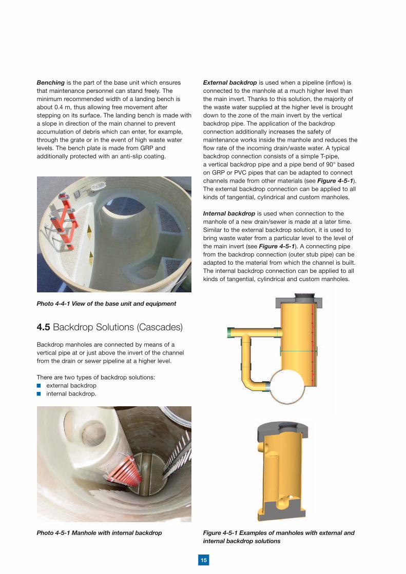
2.4 Inlet Drain Pits
An inlet drain pit directs the water collected from paved surfaces (roads, streets, parking places, truck yards etc.) to the drain system through street drains connecting the main drain with the inlet drain pit.
Two types of inlet drain pits can be distinguished: with a sediment trap without a sediment trap
An inlet drain pit usually consists of a surface part, which can be a cast iron grating and an underground part, which is formed from the superstructure of the well (relieving ring and compensation ring), and the body of the well with an inlet and outlet.
The body of the well is made of a FLOWTITE GRP pipe closed at the bottom with a concrete plug, which forms the bottom of the pit. Inlet and outlet stub pipes are laminated to the body of the well. If the drain system is to include a sand trap, pits without sediment traps are allowed. Where there is no sand trap, it is necessary to fit sediment traps into the drain. (see Figure 2-4-1).
Figure 2-4-1 Proposed design of an inlet drain pit
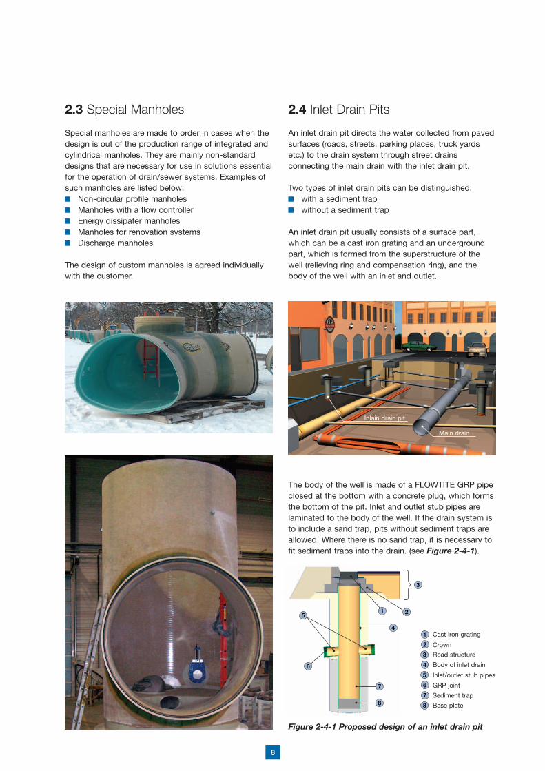
2.3 Special Manholes
Special manholes are made to order in cases when the design is out of the production range of integrated and cylindrical manholes. They are mainly non-standard designs that are necessary for use in solutions essential for the operation of drain/sewer systems. Examples of such manholes are listed below:
Non-circular profile manholes Manholes with a flow controller Energy dissipater manholes Manholes for renovation systems Discharge manholes
The design of custom manholes is agreed individually with the customer.
Cast iron grating
Crown
Road structure
Body of inlet drain
Inlet/outlet stub pipes
GRP joint
Sediment trap
Base plate
2
2
3
3
1
14
4
7
8 8
7
6
6
5
5
Inlain drain pit
Main drain

9
2.5 Separate Systems for Storm and Waste Water
The use of one manhole for both pipelines for separate sewer and storm water systems is possible for economic reasons. One pipe is built as an open channel and the second one (normally storm water) is built in as a closed channel with inspection and cleaning access.
2.6 Double-wall Solutions for Protected Areas
In water protection areas, there are special requirements for manholes and pipes for water retention. The pipe and manhole system has to be constructed as a double pipe system with inspection access. In case of leakage, pollution of the environment must be prevented by the back-up system.
Therefore, double pipe and manhole systems are supplied. The transport pipe is installed as a closed channel solution inside of the protection pipe as shown in Figure 2-6-1. At the manhole, inspection access is installed. Leakages threatening to pollute the environment can be detected directly inside the manhole.
Figure 2-6-1 GRP manhole for double pipe system for protected areas
Depending on the customer’s requirements, the system’s tightness can be additionally tested to local country regulations.

10
DN [mm]
Height H (mm)
Aprox. weight kg/m
SN 2500* SN 5000* SN 10000* thin-walled GRP pipes
1000 1000 - 12000 100 120 160
1100 1000 - 12000 120 150 190
1200 1000 - 12000 140 180 220
1300 1000 - 12000 170 210 260
1400 1000 - 12000 200 240 300
1500 1000 - 12000 220 280 340
1600 1000 - 12000 250 310 380
1700 1000 - 12000 290 350 430
1800 1000 - 12000 320 390 480
1900 1000 - 12000 350 440 540
2000 1000 - 12000 390 480 600 150
2100 1000 - 12000 430 530 650
2200 1000 - 12000 470 580 720
2300 1000 - 12000 520 640 780
2400 1000 - 12000 560 690 850 210
2500 1000 - 12000 600 750 920
2600 1000 - 12000 660 810 1000
2700 1000 - 12000 700 870 1080
2800 1000 - 12000 760 940 1160
2900 1000 - 12000 810 1000 1240
3000 1000 - 12000 870 1070 1320
3.1 Inspection Chambers
Inspection chambers are made of FLOWTITE GRP pipes as one or two piece vertical structures. They are designed to allow the proper operation of equipment installed directly on the pressure pipeline.
Chambers are available with diameters ranging up to DN 3000 and can be installed on site with or without traffic load according to local standard regulations.
Our range includes GRP structures as housings for: valves air valves emptying equipment flow metering equipment.
! Note: Due to the thrust forces which develop during the operation of the pressure equipment, the chamber design should be agreed with the local supplier.
3.2 Manholes and Chambers for Pumping Stations
GRP manholes and chambers for pumping station housings are offered mainly for:
home intermediate pumping stations system network intermediate pumping stations industrial intermediate pumping stations production process intermediate pumping stations
Pumping station housings are made of GRP pipes with diameters ranging from DN 1000 to DN 3000 mm. In the range from DN 2000 to DN 2400, the housings are made of thin-walled GRP pipes reinforced by circumferential ribs, or of FLOWTITE GRP sewage pipes. The stiffness class of the shaft unit depends on the total height of the manhole and traffic loads. The shaft unit is equipped with inlet/outlet pipes, which are connected with sewage pressure pipelines and vent pipes. Additionally, the base of the manhole has a foundation for a pump. The size and location of the foundation is always agreed upon individually for the particular type of a pump.
Covers for the entrance part of the manhole are offered in two types:
for non-traffic areas, the housing of the pumping station is equipped with a GRP cover top secured against opening (see Figure 3-2-1)
for traffic-affected areas it is necessary to use concrete cover slabs which are adapted for the particular class of traffic load (see Figure 3-2-2).
3 Manholes and Chambers in Pressure Systems
Table 3-2-1 Basic data for GRP pipes used in pumpingstation housings / manhole chambers
*Required stiffness class dependent on manhole depth and project conditions

11
Figure 3-2-1 Possible solution for a GRP pumping station housing for non-traffic areas based on a thin-walled GRP pipe, reinforced with rips
Figure 3-2-2 Possible solution for a GRP pumping station housing based on a regular FLOWTITE GRP pipe
GRP cover top entrance
Outlet for pressure pipe
Inlet for gravity pipe
Outlet for vent funnel
Foundation for pump footing
Steel holders for fastening the housing to the foundation plate
2
3
1
4
6
5
1
4
5
2
6
3
Manhole cover
Ferroconcrete slab
FLOWTITE GRP shaft
Ladder
GRP Outlet
Pressure intake
Foundation
Base slab
Outlet
Ventilation
1
2
3
4
6
5
7
8
9
10
1
2
3
4
5
6
7
8
9
10

12
4.1.1 Load–transmitting Capping Structures
The manhole’s cap transmitting loads directly onto the hatchway funnel of the manhole consists of a properly structured reinforced concrete covering slab , which is fixed directly to the top edge of the hatchway funnel . This solution is used in those areas, where surface loads (traffic) do not exceed the allowable load capacities of the manhole structure.
4.1.2 Unload–transmitting Capping Structures
The manhole’s cap transmitting the traffic load directly onto the surrounding ground consists of a load relieving ring laid directly on stabilized ground and the covering slab supported on the ring. The design of both those reinforced concrete elements must ensure the external load strength on the surface of the ground. The top edge of the hatchway funnel is protected against direct load impact by a gap under the covering slab. This solution is applied in the case of extensive traffic loads exceeding the load capacity of the GRP manhole structure.Photo 4-1-1 Concrete elements of the manhole top
Figure 4-1-1-1 Typical solution for direct load-transmitting covers of manholes/ chambers
Figure 4-1-2-1 Typical solutions for indirect load-transmitting covers of manholes/chambers
4 Equipment and Components of Manholes and Chambers
4.1 Manhole/Chambers Tops
GRP manholes and chambers can be delivered as sets with elements such as relieving rings, covering slab or compensation rings, which together constitute the manhole capping (superstructure). All elements are made of concrete or GRP or a combination of both. The top is used for permanent closure of the manhole for transmitting and distribution of external loads from traffic or surface.
There are two types of capping design: transmitting loads directly onto the manhole transmitting loads onto the surrounding ground
For economical or technical reasons it is possible to minimise the GRP height of the manhole and to use standard concrete rings or cones to reach the top ground surface without losing the advantage of havin corrosion resistant GRP parts in contact with sewage water.
! Note: Availability and technical solutions for the above chamber tops should be agreed with your local GRP manhole supplier.
Load-distributing cover
Load-distributing cover
Load-transmitting slab

13
Figure 4-2-2 Base units
4.1.3 Konus Capping Structures
For manholes and chambers with diameters different to DN 1000, a standard concrete manhole foundation ring is integrated into the cover plate supplied with manhole. This standard connection ensures compatibility to concrete rings or cones according to DIN V-4034-1.
For DN 1000 manholes and chambers a specially designed transition ring is avaiable for direct connection to standard concrete rings and cones. The transition ring is directly integrated into the GRP shaft and ensures easy connection to concrete rings and cones according DIN V-3034-1.
4.2 Manhole Foundations
Standard manholes consist of FLOWTITE GRP pipes with a customer specific foundation.As previously already described, standard cylindrical manholes are normally covered with GRP both inside and outside. The GRP covering ensures corrision resistance on all sides. It consists of a FLOWTITE pipe with a suitably designed channel or foundation
For the foundation, there are 4 main types available: with channel block with pump sump with bottom plate and uplift protection with bottom plate and w/o uplift protection
Based on project requirements (ground water level), standard manholes can be supplied with or without buoyancy protection.
Special solutions are also available on request. Please ask your local supplier.
Different channel block designs can be also agreed upon according to customer requirements. Following standard solutions are available:
the berm is on channel crown level the berm on channel springline level
Tailormade, customer-designed solutions are also available. Please ask your local dealer.
Figure 4-2-1 Types of Manhole foundations
Figure 4-1-3-1 Concrete cover plate with integrated foundation ring for standard cones
Figure 4-1-3-2 Manhole with transition ring for standard concrete cones
For manholes and chambers with diameters bigger than DN 1000, the GRP shaft unit can be alternatively equipped with an eccentric GRP reducer to scale down the diameter and reach the top ground surface with a smaller diameter. The reducer is connected with the shaft unit by using a GRP coupling or by lamination. The availability depends on country specific regulations. Please ask you local dealer.
invert on crown level invert on springline level
with channel block with pump sump
with bottom plate and uplift protection
with bottom plate and w/o uplift protection
Figure 4-1-3-3 Shaft unit equiped with GRP reducer

14
4.3 Connections to other Pipe Materials
GRP manholes and chambers can be adapted for connection with pipelines made of different materials, e.g. concrete, PE, PP, PVC, stoneware, cast iron or steel. Depending on the type of material, connection with the manhole can be made using connector pipes made from the given material, laminated directly to the manhole or using laminated sleeves geometrically adapted to the given type of material.
! Note: Availability and technical solutions for the connection of manholes with other materials should be agreed with your local GRP manhole supplier.
4.4 Ladders, Steps and Benching
Ladders are always fastened with bolts to the wall of the pipe at the position where the landing bench is the broadest. The bolts are additionally protected (sealed) by means of laminate, to prevent ground water entering the manhole. Ladders are made of GRP, stainless steel or coated metal which in case of surrounding water is an important advantage.
Figure 4-3-1 Examples of connections to different pipe materials
Figure 4-4-1 Tangential manhole with box steps
Figure 4-4-2 Tangential manhole with bent ladder
! Note: The type of steps and ladder material depends on the local regulations and might differ from country to country. For detailed information, please contact your local distributor.
On request, Steps are also available that allow access to the bottom of the channel. These are sometimes used as alternative to a bent ladder in the case of mains diameters larger than DN 1600.
Steps can be made in two materials: as GRP climbing steps as ductile iron steps.
15
4.5 Backdrop Solutions (Cascades)
Backdrop manholes are connected by means of a vertical pipe at or just above the invert of the channel from the drain or sewer pipeline at a higher level.
There are two types of backdrop solutions: external backdrop internal backdrop.
Photo 4-4-1 View of the base unit and equipment
Photo 4-5-1 Manhole with internal backdrop Figure 4-5-1 Examples of manholes with external and internal backdrop solutions
Benching is the part of the base unit which ensures that maintenance personnel can stand freely. The minimum recommended width of a landing bench is about 0.4 m, thus allowing free movement after stepping on its surface. The landing bench is made with a slope in direction of the main channel to prevent accumulation of debris which can enter, for example, through the grate or in the event of high waste water levels. The bench plate is made from GRP and additionally protected with an anti-slip coating.
External backdrop is used when a pipeline (inflow) is connected to the manhole at a much higher level than the main invert. Thanks to this solution, the majority of the waste water supplied at the higher level is brought down to the zone of the main invert by the vertical backdrop pipe. The application of the backdrop connection additionally increases the safety of maintenance works inside the manhole and reduces the flow rate of the incoming drain/waste water. A typical backdrop connection consists of a simple T-pipe, a vertical backdrop pipe and a pipe bend of 90° based on GRP or PVC pipes that can be adapted to connect channels made from other materials (see Figure 4-5-1).The external backdrop connection can be applied to all kinds of tangential, cylindrical and custom manholes.
Internal backdrop is used when connection to the manhole of a new drain/sewer is made at a later time. Similar to the external backdrop solution, it is used to bring waste water from a particular level to the level of the main invert (see Figure 4-5-1). A connecting pipe from the backdrop connection (outer stub pipe) can be adapted to the material from which the channel is built. The internal backdrop connection can be applied to all kinds of tangential, cylindrical and custom manholes.

16
Nr:
Ang
leC
onn
ecti
ng b
ranc
h fo
rIn
lets
com
men
td
egre
ece
ntes
imal
d
egre
evi
trifi
ed
clay
stre
ngth
cl
ass
PV
Cco
ncre
teP
EG
RP
sam
e in
vert
like
o
utle
t
sam
e cr
ow
n lik
e o
utle
t
diff
eren
z o
f he
igh
to t
he
out
let
in m
mD
N
0 ou
tlet
0˚0˚
gon
1 in
let
2 in
let
3 in
let
4 in
let la
min
ate
- b
uoya
ncy
pro
tect
ion
3 la
yers
cho
p s
tran
d m
att
lam
inat
e -
bra
nch
DN
-
laye
rs
wid
th
lam
inat
e -
bra
nch
DN
-
laye
rs
wid
th
lam
inat
e -
bra
nch
DN
-
laye
rs
wid
th
lam
inat
e -
bra
nch
DN
-
laye
rs
wid
th
with
out
chan
nel
with
cha
nnel
leve
l of
ber
m1/
22/
31
conc
rete
conc
rete
with
coa
ting
GR
P m
onol
ithic
GR
P-P
red
l (p
reca
st c
hann
el b
lock
)
dep
th H
k
m
m
cast
iron
ste
ps
acco
rdin
g D
IN E
N 1
3101
safe
ty m
anho
le s
tep
s ac
cord
ing
DIN
EN
195
55
lad
der
....
......
......
...
entr
ance
aid
s ...
......
......
......
Appendix AOrder form for drain/ sewage GRP manholes
Co
mp
any:
Co
nstr
ucti
on
site
:P
iece
:D
ate:
Dat
e o
f d
eliv
ery:
Tim
e [m
in.]
:
Co
mm
ents
:
- re
info
rced
con
cret
e co
verp
late
Ø...
......
......
....x
......
......
......
mm
- w
ith s
lide
safe
ty /
with
1/2
cou
plin
g-
open
ing
Ø...
......
......
......
......
......
....m
m-
......
......
......
......
......
......
......
......
......
......

17
tang
enti
al D
N
/
SN
dep
th
mm
sew
er p
ipe
DN
x
m
m
sew
er p
ipe,
cha
nnel
unb
end
ed
sew
er p
ipe,
cha
nnel
ben
ded
till
30°
sew
er p
ipe,
cha
nnel
ben
ded
till
60°
sew
er p
ipe,
cha
nnel
ben
ded
till
90°
coup
ling
DN
pie
ce
do
me
acce
ss D
N
x
mm
coup
ling
DN
pie
ce
do
me
acce
ss e
long
atio
n D
N
x
m
m
wit
h co
uplin
g
wit
hout
co
uplin
g
load
dis
trib
utio
n Ø
x
m
m
rein
forc
ed c
onc
rete
co
verp
late
wit
h 1/
2 co
uplin
g
lad
der
GR
Pst
ainl
ess
stee
l
entr
ance
aid
s (s
tain
less
ste
el)
Appendix BOrder form for tangential manhole with berm
Co
mp
any:
Co
nstr
ucti
on
site
:P
iece
:D
ate:
Nr:
Dat
e o
f d
eliv
ery:
tim
e [m
in.]
:
18
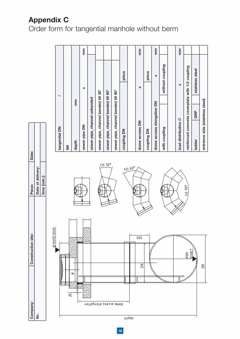
Appendix COrder form for tangential manhole without berm
tang
enti
al D
N
/
SN
dep
th
mm
sew
er p
ipe
DN
x
m
m
sew
er p
ipe,
cha
nnel
unb
end
ed
sew
er p
ipe,
cha
nnel
ben
ded
till
30°
sew
er p
ipe,
cha
nnel
ben
ded
till
60°
sew
er p
ipe,
cha
nnel
ben
ded
till
90°
coup
ling
DN
pie
ce
do
me
acce
ss D
N
x
mm
coup
ling
DN
pie
ce
do
me
acce
ss e
long
atio
n D
N
x
m
m
wit
h co
uplin
g
wit
hout
co
uplin
g
load
dis
trib
utio
n Ø
x
m
m
rein
forc
ed c
onc
rete
co
verp
late
wit
h 1/
2 co
uplin
g
lad
der
GR
Pst
ainl
ess
stee
l
entr
ance
aid
s (s
tain
less
ste
el)
Co
mp
any:
Co
nstr
ucti
on
site
:P
iece
:D
ate:
Nr:
Dat
e o
f d
eliv
ery:
tim
e [m
in.]
:

19
Dimentions of pump housing
Diameter DN [mm]
Height H [mm]
Pressure pipeline
DNT [mm]
Material* .............................................
Angle αT1 [°]
Height hT1 [mm]
Sewer inlets
DNG1 [mm]
Material* .............................................
Angle αG1 [°]
Height hG1 [mm]
DNG2 [mm]
Material* .............................................
Angle αG2 [°]
Height hG2 [mm]
DNG3 [mm]
Material* .............................................
Angle αG3 [°]
Height hG3 [mm]
Vent outlet
DNW [mm]
Material* .............................................
Quantity [°]
Dimensions of entrance
Width W1 [mm]
Length [mm]
Dimensions of fundations for a pump
P1 [mm]
P2 [mm]
P3 [mm]
Appendix DOrder form for a manhole as a pump housing
Company: Construction site: Piece: Date:
Nr: Date of delivery:
time [min.]:
Note:* - specify pipe material typeInlets/outlets ordinates are calculated in relation to ground level
This handbook is intended as a guide only. All values listed in the product specifications are nominal. Unsatisfactory product results may occur due to environmental fluctuations, variations in operating procedures, or interpolation of data. We highly recommend that any personnel using this data have specialised training and experience in the application of these products and their normal installation and operating conditions. The engineering staff should always be consulted before any of these products are installed to ensure the suitability of the products for their intended purpose and applications. We hereby state that we do not accept any liability, and will not be held liable, for any losses or damage which may result from the installation or use of any products listed in this handbook as we have not determined the degree of care required for product installation or service. We reserve the right to revise this data, as necessary, without notice. We welcome comments regarding this handbook.
MH
B V
1 04
-11-
EN
G
Distributed by:
AMITECH Service AG Turmstrasse 286300 Zug-SteinhausenSwitzerland Phone: + 41 41 748 07 20Fax: + 41 41 748 07 [email protected]