Unit 1 Careers in Greenhouse Management Greenhouse Management.

1
GROWSPAN™ ESTATE PRO SMALL GREENHOUSES
Revision date: 04.19.16
GrowSpan™ Estate Pro Small Greenhouse
STK# DIMENSIONS103846 7'-2" W x 6'-3" H x 9'-9" L
Photo may show a different but similar model. Vent locations may differ from actual model.
©2016 GrowSpanAll Rights Reserved. Reproduction is prohibited without permission.

GROWSPAN™ ESTATE PRO SMALL GREENHOUSES
2 Revision date: 04.19.16
YOU MUST READ THIS DOCUMENT BEFORE YOU BEGIN TO ASSEMBLE THE SHELTER.
Thank you for purchasing this Growspan™ greenhouse. When properly assembled and maintained, this product will provide years of reliable service. These instructions include helpful hints and important information needed to safely assemble and properly maintain the greenhouse. Please read these instructions before you begin.
SAFETY PRECAUTIONS
• Wear eye protection and gloves when handling panels and frame parts.
• Frame is metal. Use a portable GFCI when working with power tools and cords.
• Do not climb on the greenhouse or framing during or after construction.
• Do not occupy the greenhouse during high winds, tornadoes, or hurricanes.
• Provide adequate ventilation if the structure is enclosed.
• Do not store hazardous materials in the greenhouse.
• Provide proper ingress and egress to prevent entrapment.
ANCHORING INSTRUCTIONS
Prior to assembling this greenhouse, please read the MUST READ document included with the shipment.
WARNING: The anchor assembly is an integral part of the greenhouse construction. Improper anchoring may cause greenhouse instability and failure of the structure. Failing to anchor the greenhouse properly will void the manufacturer’s warranty and may cause serious injury and damage.
LOCATION
Choosing the proper location is an important step before you begin to assemble the structure.
The following suggestions and precautions will help you determine whether your selected location is the best location.
• Never erect the structure under power lines.
• Identify whether underground cables and pipes are present before preparing the site or anchoring the structure.
• Location should be away from structures that could cause snow to drift on or around the building.
• Do not position the greenhouse where large loads such as snow and ice, large tree branches, or other overhead obstacles could fall.
• Always check local building codes before you begin.
SITE
After choosing a location, proper preparation of the site is essential. The following site characteristics will help ensure the integrity of the structure.
• A level site is required. The site must be level to properly and safely erect and anchor the structure.
• Drainage: Water draining off the structure and from areas surrounding the site should drain away from the site to prevent damage to the site, the structure, and contents of the structure.
WARNING: The individuals assembling this structure are responsible for designing and furnishing all temporary bracing, shoring and support needed during the assembly process.
For safety reasons, those who are not familiar with recognized construction methods and techniques must seek the help of a qualified contractor.
ASSEMBLY NOTE
The assembly of this greenhouse is not complex; however, it does take time and additional assistance. For best results, read through these instructions before you begin to get an overview of the entire assembly. Then, follow these instructions as presented.
Examine all diagrams and photos and verify that you have selected the proper parts. Do not mix parts from different bags. When checking parts, place the parts and the numbered bag in a separate area to prevent mixing the parts and to aid in the assembly process.
IMPORTANT! INVENTORY THE PARTS
1. Open each box and use the Bill of Material included in each box to inventory of the contents of each bag.
2. Keep all parts from one bag separate from the parts in another bag after opening. Keep each numbered bag and its contents together for assembly.
3. Call Customer Service at 1.800.245.9881 to report any missing parts before you begin.

3
GROWSPAN™ ESTATE PRO SMALL GREENHOUSES
Revision date: 04.19.16
ASSEMBLY PROCEDURE
Following the instructions as presented will help ensure the proper assembly of your greenhouse. Failing to follow these steps may result in an improperly assembled and anchored greenhouse and may void all warranty and protection the owner is entitled to.
The steps outlining the assembly process are as follows:
1. Verify that all parts are included in the shipment. Notify Customer Service for questions or concerns.
2. Read these instructions and all additional documentation included with the shipment before you begin assembling the greenhouse. Use these instructions and the Bill of Material (inside each box) when assembling the greenhouse.
3. Gather the tools, bracing, ladders (and lifts if applicable), and assistance needed to assemble the greenhouse.
4. Re-evaluate the location and site based on the information and precautions presented in the documentation included with the shipment.
5. Lay out the site (if this has not been completed).
6. Assemble the base frame (additional purchase required) and greenhouse components in the order they are presented in these instructions.
7. Anchor the greenhouse as instructed.
8. Read the greenhouse care and maintenance information at the end of these instructions.
9. Complete and return all warranty information as instructed.
REQUIRED TOOLS
The following list identifies the main tools needed to assemble the shelter. Additional tools and supports may be needed depending on the structure, location, and application.
• Tape measure or measuring device
• Metric and standard wrench set (or ratchet and socket set)
• Ladders and/or work platforms
• Caulk gun for silicone application
• Utility knife, tape or marker
• Carpenter's square or similar tool
GREENHOUSE PARTS
All greenhouse sections (e.g., roof, sides, end walls, etc.) are shipped in individually numbered bags within a larger box. To prevent mixing the parts during assembly, select the bags as instructed and open that bag only and assemble its contents. OPEN BAGS AS INSTRUCTED TO PREVENT MIXING OF THE CONTENTS.
NOTE: Some photos and diagrams throughout these instructions may show a greenhouse with slightly different dimensions, color, or design. The assembly procedures are identical regardless of these differences. Notable differences are addressed. For a quick overview of this greenhouse, consult the diagrams in the Quick Start section near the back of these instructions.
Those not familiar with the assembly of similar structures and the use of common hand tools must seek the assistance of someone with such experience.
WARNING: Do not allow the polycarbonate panels to remain in direct sunlight until they are installed. Doing so will cause the protective film to become difficult if not impossible to remove.
Consult Page 34 for additional polycarbonate and how to use vent tape (additional purchase required) information before installing any polycarbonate panel.
BAG CONTENTS
The following list identifies the main components of each box. Use this information during the greenhouse assembly.
Box 1 of 2 (also contains one (1) bag of extra parts)
• Bag #1: End Wall (with door)
• Bag #2: End Wall (without door)
• Bag #3/4: Sidewall (2 identical bags with this number)
• Bag #5: Roof
• Bag #6: Door
• Bag #7: Vent (2 identical bags with this number)
Box 2 of 2 (also contains one (1) bag of extra parts)
• All lettered panels
• 2 boxes of plastic profile
• Sealant and 1 bag with gutter rail ends

GROWSPAN™ ESTATE PRO SMALL GREENHOUSES
4 Revision date: 04.19.16
Ridge Beam Top Bracket
Sliding Door Track
Door FrameDiagonal Strut
Base Rail
Vertical Support: Side Wall
Gutter Rail
Rafters
OVERVIEW
This section is an overview of the process for assembling your greenhouse. See illustration below to identify main parts of greenhouse.
1. Locate the required parts for each assembly procedure.
2. Preassemble the base frame (if used—additional purchase required), end walls, and side walls.
3. Assemble frame and install the ridge beam and rafters.
4. Anchor and square the greenhouse.
5. Assemble and attach vents and sliding door.
6. Install polycarbonate door panels and track.
7. Attach gutter rail ends.
8. Install the side, end, and roof polycarbonate panels.
Track Support
PART IDENTIFICATION NUMBERS
All main parts include a stamped ID number. Use this number when selecting the required parts during the assembly.
NOTE: The locations of the part numbers on the components may vary. Refer to the Bill of Materials shipped within each box for a description of each part.
17
17
Estate Pro SmallGreenhouse
5
GROWSPAN™ ESTATE PRO SMALL GREENHOUSES
Revision date: 04.19.16
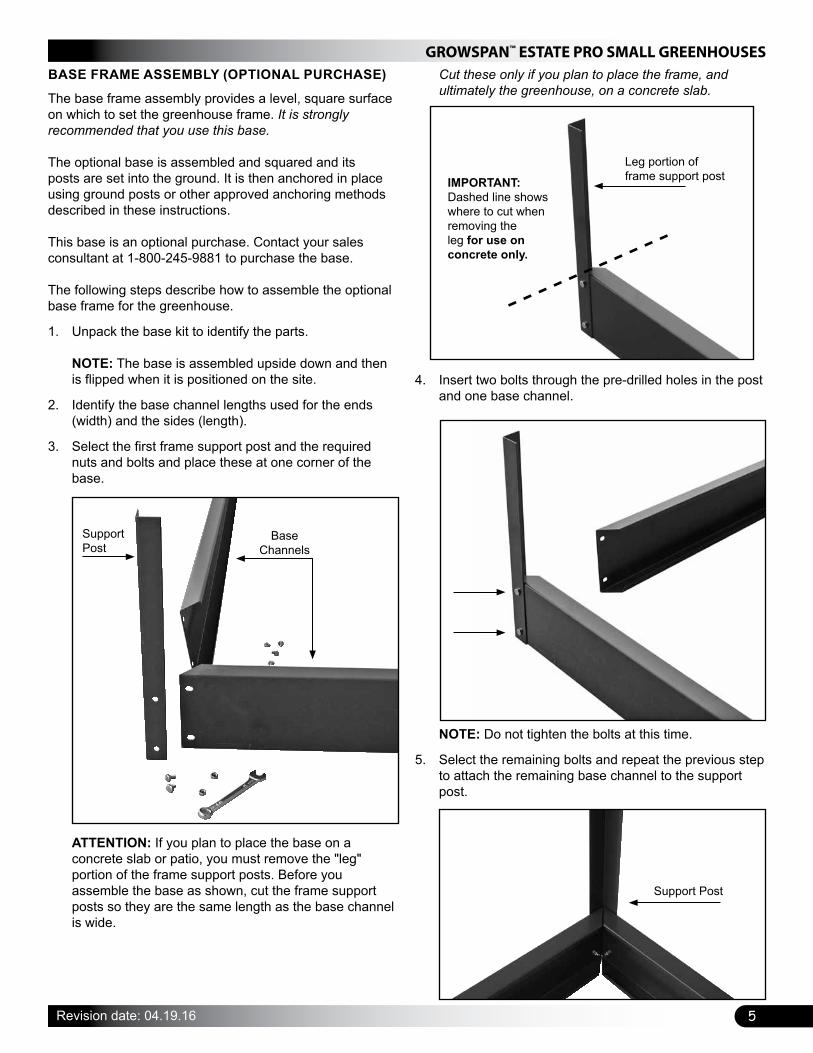
BASE FRAME ASSEMBLY (OPTIONAL PURCHASE)
The base frame assembly provides a level, square surface on which to set the greenhouse frame. It is strongly recommended that you use this base. The optional base is assembled and squared and its posts are set into the ground. It is then anchored in place using ground posts or other approved anchoring methods described in these instructions. This base is an optional purchase. Contact your sales consultant at 1-800-245-9881 to purchase the base. The following steps describe how to assemble the optional base frame for the greenhouse.
1. Unpack the base kit to identify the parts. NOTE: The base is assembled upside down and then is flipped when it is positioned on the site.
2. Identify the base channel lengths used for the ends (width) and the sides (length).
3. Select the first frame support post and the required nuts and bolts and place these at one corner of the base.
ATTENTION: If you plan to place the base on a concrete slab or patio, you must remove the "leg" portion of the frame support posts. Before you assemble the base as shown, cut the frame support posts so they are the same length as the base channel is wide.
Support Post
Base Channels
Cut these only if you plan to place the frame, and ultimately the greenhouse, on a concrete slab.
4. Insert two bolts through the pre-drilled holes in the post and one base channel.
NOTE: Do not tighten the bolts at this time.
5. Select the remaining bolts and repeat the previous step to attach the remaining base channel to the support post.
Leg portion of frame support postIMPORTANT:
Dashed line shows where to cut when removing the leg for use on concrete only.
Support Post

GROWSPAN™ ESTATE PRO SMALL GREENHOUSES
6 Revision date: 04.19.16
BASE FRAME ASSEMBLY (CONTINUED)
6. Verify that the post is straight and tighten the bolts
7. Repeat the procedure to attach the remaining support posts to the base channels.
8. After the frame is assembled and all bolts are tight, flip the base over and set it on the site.
9. Continue with the next procedure.
SQUARE THE BASE (if used)
Before the support posts of the base are driven into the ground and before the assembled greenhouse frame is set on and secured to the base, you must square the base assembly and anchor the base to the site. ATTENTION: If you are setting the base and greenhouse on a patio or concrete slab, set the assembled base on the site and continue with the greenhouse assembly procedures that follow. Do not square the base at this time. This base and greenhouse require a level site. Before setting the base or greenhouse frame (or both) in place, you must level the site. The easiest way to square the base is to measure diagonally from corner to corner. Complete these steps: NOTE: The following procedure describes how to square the base on a prepared site and drive the base support posts into the ground.
1. Position the assembled base on the site as shown below.
2. Measure diagonally from corner-to-corner.
Top of base
Top of base
NOTE: The frame is square when both measurements are the same.
3. When the frame is square, tap the support posts into the ground to set the frame in place and recheck the measurements. NOTE: Place a block of wood on top of the base channel and support post and hammer on the wood to protect the frame when driving the posts into place.
4. Continue to drive the posts to the desired depth. NOTE: Use a level (or string a line) to verify that the base remains level when set into the ground
5. After setting the base on the site, continue with the greenhouse assembly.
EXTRA PARTS PROVIDED FOR GREENHOUSE
ATTENTION: TO AVOID TWISTING OFF OR DAMAGING THE FASTENERS, DO NOT OVERTIGHTEN.
FOR YOUR CONVENIENCE, ADDITIONAL FASTENERS AND PLASTIC MOLDING CAN BE FOUND IN THE "EXTRA PARTS" BAG OR BOX.
REFER TO THE BILL OF MATERIALS FOR A LIST OF THE FASTENERS AND MOLDING CONTAINED IN THAT BAG OR BOX.
The plastic profile can be trimmed to the required length if a piece is misplaced or damaged during installation.
IMPORTANT: Consult the "extra parts" for items you need before contacting customer service to request a replacement for damaged or missing parts or fasteners.
7
GROWSPAN™ ESTATE PRO SMALL GREENHOUSES
Revision date: 04.19.16
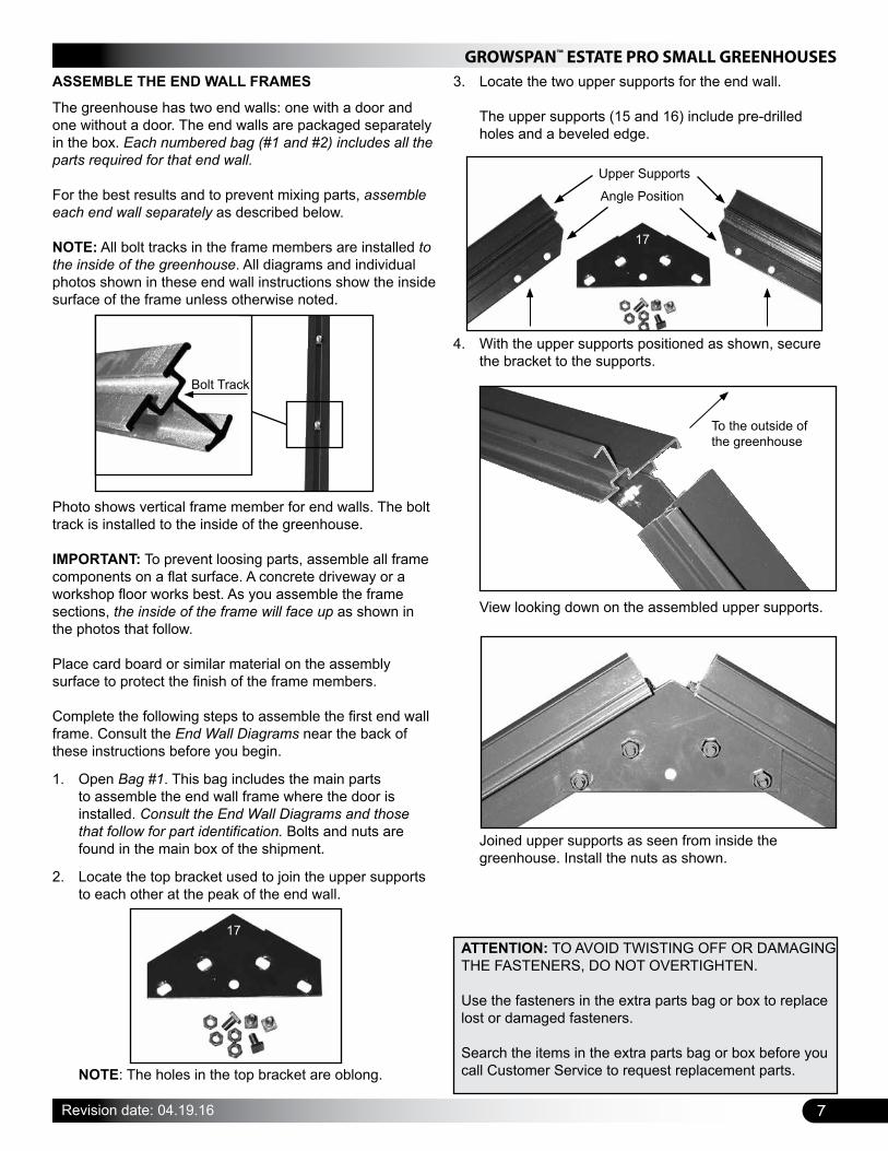
ASSEMBLE THE END WALL FRAMES
The greenhouse has two end walls: one with a door and one without a door. The end walls are packaged separately in the box. Each numbered bag (#1 and #2) includes all the parts required for that end wall.
For the best results and to prevent mixing parts, assemble each end wall separately as described below.
NOTE: All bolt tracks in the frame members are installed to the inside of the greenhouse. All diagrams and individual photos shown in these end wall instructions show the inside surface of the frame unless otherwise noted.
Photo shows vertical frame member for end walls. The bolt track is installed to the inside of the greenhouse. IMPORTANT: To prevent loosing parts, assemble all frame components on a flat surface. A concrete driveway or a workshop floor works best. As you assemble the frame sections, the inside of the frame will face up as shown in the photos that follow. Place card board or similar material on the assembly surface to protect the finish of the frame members.
Complete the following steps to assemble the first end wall frame. Consult the End Wall Diagrams near the back of these instructions before you begin.
1. Open Bag #1. This bag includes the main parts to assemble the end wall frame where the door is installed. Consult the End Wall Diagrams and those that follow for part identification. Bolts and nuts are found in the main box of the shipment.
2. Locate the top bracket used to join the upper supports to each other at the peak of the end wall.
Bolt Track
NOTE: The holes in the top bracket are oblong.
3. Locate the two upper supports for the end wall. The upper supports (15 and 16) include pre-drilled holes and a beveled edge.
4. With the upper supports positioned as shown, secure the bracket to the supports.
View looking down on the assembled upper supports.
Joined upper supports as seen from inside the greenhouse. Install the nuts as shown.
17
To the outside of the greenhouse
ATTENTION: TO AVOID TWISTING OFF OR DAMAGING THE FASTENERS, DO NOT OVERTIGHTEN.
Use the fasteners in the extra parts bag or box to replace lost or damaged fasteners.
Search the items in the extra parts bag or box before you call Customer Service to request replacement parts.
17
Angle Position
Upper Supports
GROWSPAN™ ESTATE PRO SMALL GREENHOUSES
8 Revision date: 04.19.16
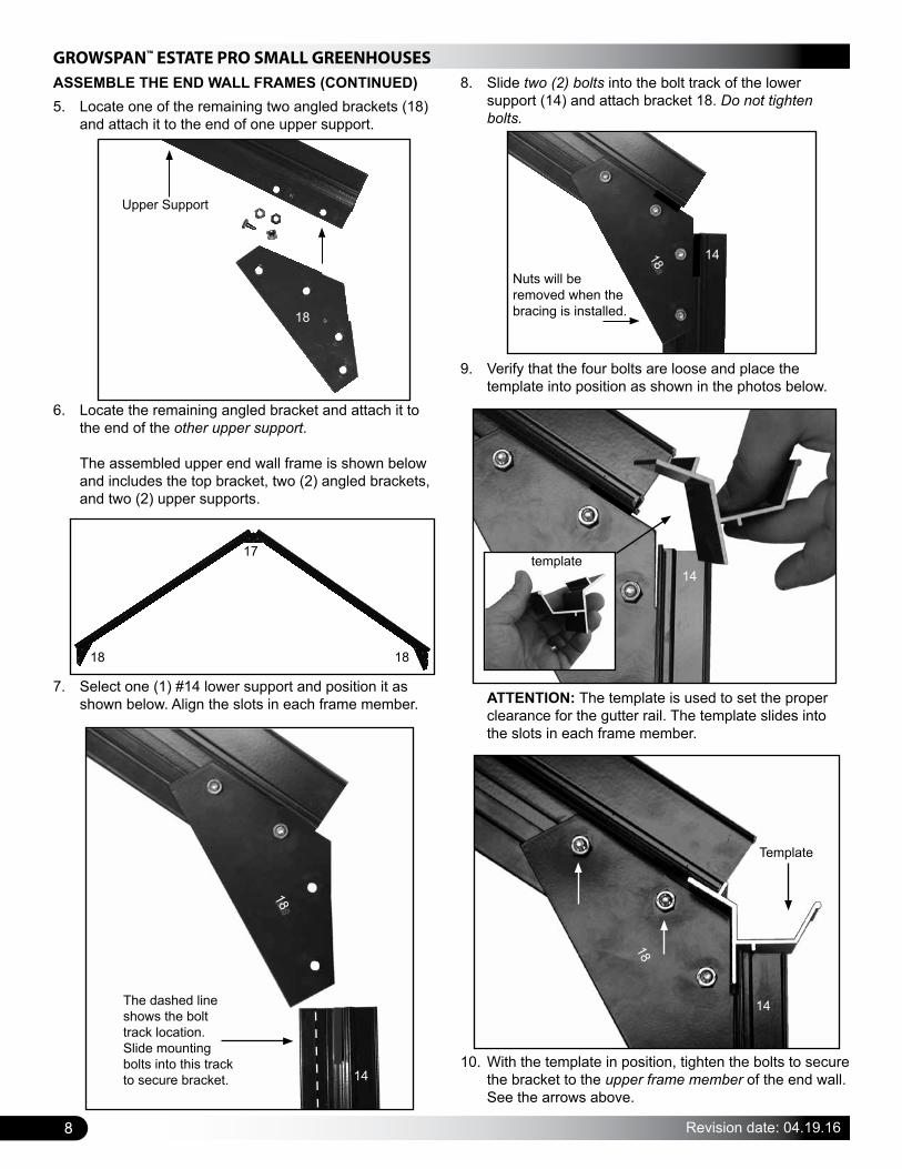
5. Locate one of the remaining two angled brackets (18) and attach it to the end of one upper support.
ASSEMBLE THE END WALL FRAMES (CONTINUED)
6. Locate the remaining angled bracket and attach it to the end of the other upper support. The assembled upper end wall frame is shown below and includes the top bracket, two (2) angled brackets, and two (2) upper supports.
7. Select one (1) #14 lower support and position it as shown below. Align the slots in each frame member.
8. Slide two (2) bolts into the bolt track of the lower support (14) and attach bracket 18. Do not tighten bolts.
Upper Support
18
9. Verify that the four bolts are loose and place the template into position as shown in the photos below.
ATTENTION: The template is used to set the proper clearance for the gutter rail. The template slides into the slots in each frame member.
10. With the template in position, tighten the bolts to secure the bracket to the upper frame member of the end wall. See the arrows above.
Template
14
18Nuts will be removed when the bracing is installed.
18 14
1818
17
14
The dashed line shows the bolt track location. Slide mounting bolts into this track to secure bracket.
18
template14
9
GROWSPAN™ ESTATE PRO SMALL GREENHOUSES
Revision date: 04.19.16
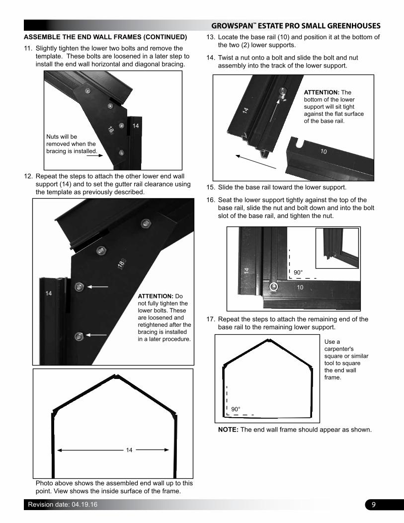
11. Slightly tighten the lower two bolts and remove the template. These bolts are loosened in a later step to install the end wall horizontal and diagonal bracing.
12. Repeat the steps to attach the other lower end wall support (14) and to set the gutter rail clearance using the template as previously described.
Photo above shows the assembled end wall up to this point. View shows the inside surface of the frame.
14
10
ATTENTION: The bottom of the lower support will sit tight against the flat surface of the base rail.
14
13. Locate the base rail (10) and position it at the bottom of the two (2) lower supports.
14. Twist a nut onto a bolt and slide the bolt and nut assembly into the track of the lower support.
15. Slide the base rail toward the lower support.
16. Seat the lower support tightly against the top of the base rail, slide the nut and bolt down and into the bolt slot of the base rail, and tighten the nut.
14
10
90°
17. Repeat the steps to attach the remaining end of the base rail to the remaining lower support.
90°
Use a carpenter's square or similar tool to square the end wall frame.
NOTE: The end wall frame should appear as shown.
ASSEMBLE THE END WALL FRAMES (CONTINUED)
Nuts will be removed when the bracing is installed.
18 14
14 ATTENTION: Do not fully tighten the lower bolts. These are loosened and retightened after the bracing is installed in a later procedure.
18

GROWSPAN™ ESTATE PRO SMALL GREENHOUSES
10 Revision date: 04.19.16
18. Locate the two vertical supports (11) that run between the upper supports and the base rail and slide three (3) bolts into the track of each vertical support.
Bolt Track
Vertical Support
11
These bolts are used to attach the vertical support to the upper support and the base rail. The remaining center bolt is used to secure the short horizontal braces of the end frame. See the End Frame Diagrams if needed.
19. Select the header (19-2) and insert the top bolt of the vertical support (11) through the pre-drilled hole in the header (19-2).
19-2
Upper Support
20. Insert the bolt through the pre-drilled hole in the upper support and tighten the nut until snug.
21. Repeat the steps to attach the remaining end of the header (19-2) to the remaining vertical support (11) and upper support.
NOTE: When installed properly, the header (19-2) is sandwiched between the vertical supports and the upper supports as shown above and in the photos that follow. (Frame as seen from the bolt track side.)
ASSEMBLE THE END WALL FRAMES (CONTINUED)
19-2
Header90°
NOTE: Place the header over the upper bolt in the bolt track of the vertical support as shown in the diagram above.
Photo above shows the same assembly as seen from the outside (or opposite side) of the frame. The pre-drilled holes (see insert) in the header (19-2) are positioned to the outside (or front) of the greenhouse The pre-drilled holes are used when the door track is attached to the outside of the end wall later.
The dashed line shows the edge of the upper support.
Header is sandwiched between the vertical support (11) and the upper support.
11
GROWSPAN™ ESTATE PRO SMALL GREENHOUSES
Revision date: 04.19.16
ASSEMBLE THE END WALL FRAMES (CONTINUED)
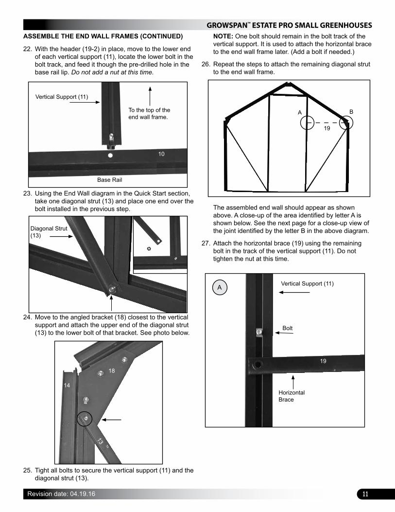
Vertical Support (11)
To the top of the end wall frame.
Base Rail
10
23. Using the End Wall diagram in the Quick Start section, take one diagonal strut (13) and place one end over the bolt installed in the previous step.
Diagonal Strut (13)
24. Move to the angled bracket (18) closest to the vertical support and attach the upper end of the diagonal strut (13) to the lower bolt of that bracket. See photo below.
NOTE: One bolt should remain in the bolt track of the vertical support. It is used to attach the horizontal brace to the end wall frame later. (Add a bolt if needed.)
26. Repeat the steps to attach the remaining diagonal strut to the end wall frame.
The assembled end wall should appear as shown above. A close-up of the area identified by letter A is shown below. See the next page for a close-up view of the joint identified by the letter B in the above diagram.
27. Attach the horizontal brace (19) using the remaining bolt in the track of the vertical support (11). Do not tighten the nut at this time.
Bolt
Horizontal Brace
19
Vertical Support (11)A
A B
19
22. With the header (19-2) in place, move to the lower end of each vertical support (11), locate the lower bolt in the bolt track, and feed it though the pre-drilled hole in the base rail lip. Do not add a nut at this time.
18
14
13
25. Tight all bolts to secure the vertical support (11) and the diagonal strut (13).
GROWSPAN™ ESTATE PRO SMALL GREENHOUSES
12 Revision date: 04.19.16
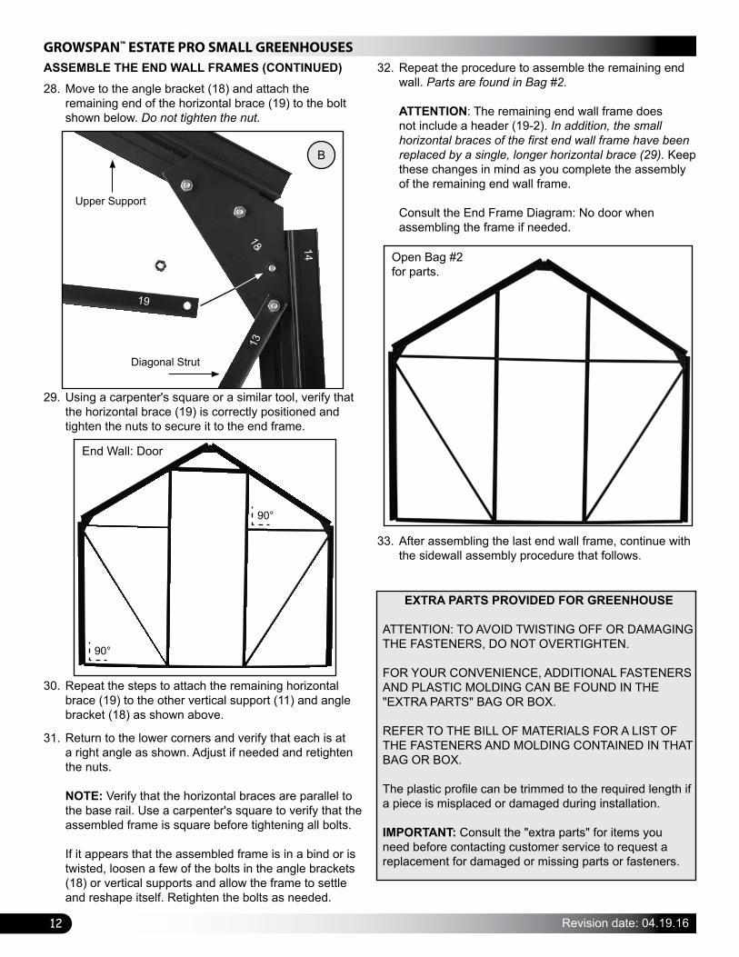
ASSEMBLE THE END WALL FRAMES (CONTINUED)
29. Using a carpenter's square or a similar tool, verify that the horizontal brace (19) is correctly positioned and tighten the nuts to secure it to the end frame.
30. Repeat the steps to attach the remaining horizontal brace (19) to the other vertical support (11) and angle bracket (18) as shown above.
31. Return to the lower corners and verify that each is at a right angle as shown. Adjust if needed and retighten the nuts. NOTE: Verify that the horizontal braces are parallel to the base rail. Use a carpenter's square to verify that the assembled frame is square before tightening all bolts. If it appears that the assembled frame is in a bind or is twisted, loosen a few of the bolts in the angle brackets (18) or vertical supports and allow the frame to settle and reshape itself. Retighten the bolts as needed.
32. Repeat the procedure to assemble the remaining end wall. Parts are found in Bag #2. ATTENTION: The remaining end wall frame does not include a header (19-2). In addition, the small horizontal braces of the first end wall frame have been replaced by a single, longer horizontal brace (29). Keep these changes in mind as you complete the assembly of the remaining end wall frame. Consult the End Frame Diagram: No door when assembling the frame if needed.
33. After assembling the last end wall frame, continue with the sidewall assembly procedure that follows.
Open Bag #2 for parts.
90°
90°
End Wall: Door
B
Upper Support
Diagonal Strut
14
18
19
13
28. Move to the angle bracket (18) and attach the remaining end of the horizontal brace (19) to the bolt shown below. Do not tighten the nut.
EXTRA PARTS PROVIDED FOR GREENHOUSE
ATTENTION: TO AVOID TWISTING OFF OR DAMAGING THE FASTENERS, DO NOT OVERTIGHTEN.
FOR YOUR CONVENIENCE, ADDITIONAL FASTENERS AND PLASTIC MOLDING CAN BE FOUND IN THE "EXTRA PARTS" BAG OR BOX.
REFER TO THE BILL OF MATERIALS FOR A LIST OF THE FASTENERS AND MOLDING CONTAINED IN THAT BAG OR BOX.
The plastic profile can be trimmed to the required length if a piece is misplaced or damaged during installation.
IMPORTANT: Consult the "extra parts" for items you need before contacting customer service to request a replacement for damaged or missing parts or fasteners.

13
GROWSPAN™ ESTATE PRO SMALL GREENHOUSES
Revision date: 04.19.16
SIDEWALL ASSEMBLY
After both end wall frames are assembled, locate the bags labeled #3/4—there are two (2) of these: one for each sidewall. Open only one of these at this time and assemble its contents as described below.
ATTENTION: Consult the Sidewall Frame Diagram below and in the Quick Start section for a description of parts. All vertical supports are installed with the bolt track to the inside of the greenhouse.
These steps describe one way to assemble the sidewalls:
1. Unpack the parts for one sidewall and position them on a flat surface for assembly. The gutter rail is placed at the top of the sidewall and the base rail is positioned at the bottom of the sidewall.
2. Select the vertical supports (31) for the sidewall and slide two (2) bolts into the bolt track of each support. NOTE: One bolt is used to attach the vertical support to the gutter rail (32) and the other is used to attach the support to the base rail (30). For the first vertical support at each end of the sidewall, the bolts are also used to attach the diagonal struts to the frame.
3. Attach each vertical support to the gutter rail by inserting the bolt through the pre-drilled hole in the gutter rail. Do not tighten nuts at this time. NOTE: The slotted hole at each end of the gutter rail is used to attach the end wall frame assembly to the sidewall. Use the diagram to position the first vertical support in the correct location. For the end vertical supports, place a diagonal strut on the bolt and install the nut. Do not tighten the nuts at this time.
The photo above shows the vertical support and diagonal strut as attached to the gutter rail of the sidewall.
4. Insert the remaining bolts, located in the bolt tracks of the vertical supports, into the corresponding pre-drilled holes of the base rail.
33
Photo shows the gutter rail as seen from the outside. The dashed line shows where the end wall frame assemblies will attached.
Gutter Rail (32)
View shows the sidewall from the outside. 31
Assembly Notes• The two (2) sidewalls are identical and are assembled
the same. Position the diagonal struts as shown above or angle them from the top corner down to the bottom of the vertical support. The top (or bottom) of the brace will remain loose until the assembled sidewall is attached to the corner of the end wall.
• Use a carpenter's square or similar tool to ensure a 90° angle between the vertical support (31) and the gutter rail (32) and the support and the base rail (30).
• Do not tighten the bolt where the diagonal brace (33) is attached until the sidewall is attached to the end wall.
32
30
33
View shows the inside or bolt track side of the sidewall.
31 31 31
Base Rail
90°
90°
Gutter Rail (32)
Bolt tracks face up during assembly.
32
32
33
31
GROWSPAN™ ESTATE PRO SMALL GREENHOUSES
14 Revision date: 04.19.16
SIDEWALL ASSEMBLY (CONTINUED)
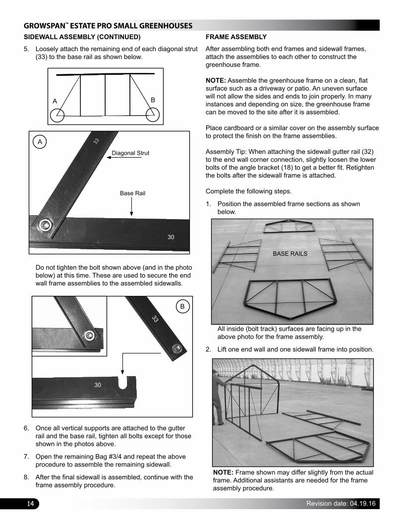
5. Loosely attach the remaining end of each diagonal strut (33) to the base rail as shown below.
Do not tighten the bolt shown above (and in the photo below) at this time. These are used to secure the end wall frame assemblies to the assembled sidewalls.
6. Once all vertical supports are attached to the gutter rail and the base rail, tighten all bolts except for those shown in the photos above.
7. Open the remaining Bag #3/4 and repeat the above procedure to assemble the remaining sidewall.
8. After the final sidewall is assembled, continue with the frame assembly procedure.
FRAME ASSEMBLY
After assembling both end frames and sidewall frames, attach the assemblies to each other to construct the greenhouse frame.
NOTE: Assemble the greenhouse frame on a clean, flat surface such as a driveway or patio. An uneven surface will not allow the sides and ends to join properly. In many instances and depending on size, the greenhouse frame can be moved to the site after it is assembled.
Place cardboard or a similar cover on the assembly surface to protect the finish on the frame assemblies.
Assembly Tip: When attaching the sidewall gutter rail (32) to the end wall corner connection, slightly loosen the lower bolts of the angle bracket (18) to get a better fit. Retighten the bolts after the sidewall frame is attached.
Complete the following steps.
1. Position the assembled frame sections as shown below.
All inside (bolt track) surfaces are facing up in the above photo for the frame assembly.
2. Lift one end wall and one sidewall frame into position.
BASE RAILS
NOTE: Frame shown may differ slightly from the actual frame. Additional assistants are needed for the frame assembly procedure.
A B
Base Rail
Diagonal Strut
30
A
30
33
B
15
GROWSPAN™ ESTATE PRO SMALL GREENHOUSES
Revision date: 04.19.16
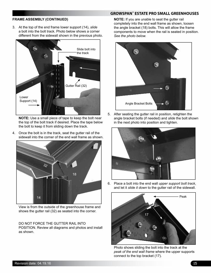
3. At the top of the end frame lower support (14), slide a bolt into the bolt track. Photo below shows a corner different from the sidewall shown in the previous photo.
FRAME ASSEMBLY (CONTINUED)
NOTE: Use a small piece of tape to keep the bolt near the top of the bolt track if desired. Place the tape below the bolt to keep it from sliding down the track.
4. Once the bolt is in the track, seat the gutter rail of the sidewall into the corner of the end wall frame as shown.
View is from the outside of the greenhouse frame and shows the gutter rail (32) as seated into the corner. DO NOT FORCE THE GUTTER RAIL INTO POSITION. Review all diagrams and photos and install as shown.
5. After seating the gutter rail in position, retighten the angle bracket bolts (if needed) and slide the bolt shown in the next photo into position and tighten.
6. Place a bolt into the end wall upper support bolt track, and let it slide it down to the gutter rail of the sidewall.
Photo shows sliding the bolt into the track at the peak of the end wall frame where the upper supports connect to the top bracket (17).
Angle Bracket Bolts
Slide bolt into the track
Gutter Rail (32)
Lower Support (14)
32
18
14 Peak
17
NOTE: If you are unable to seat the gutter rail completely into the end wall frame as shown, loosen the angle bracket (18) bolts. This will allow the frame components to move when the rail is seated in position. See the photo below.
GROWSPAN™ ESTATE PRO SMALL GREENHOUSES
16 Revision date: 04.19.16
FRAME ASSEMBLY (CONTINUED)
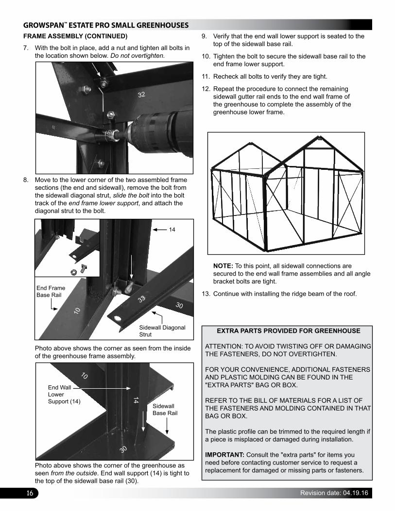
7. With the bolt in place, add a nut and tighten all bolts in the location shown below. Do not overtighten.
8. Move to the lower corner of the two assembled frame sections (the end and sidewall), remove the bolt from the sidewall diagonal strut, slide the bolt into the bolt track of the end frame lower support, and attach the diagonal strut to the bolt.
Photo above shows the corner as seen from the inside of the greenhouse frame assembly.
Photo above shows the corner of the greenhouse as seen from the outside. End wall support (14) is tight to the top of the sidewall base rail (30).
9. Verify that the end wall lower support is seated to the top of the sidewall base rail.
10. Tighten the bolt to secure the sidewall base rail to the end frame lower support.
11. Recheck all bolts to verify they are tight.
12. Repeat the procedure to connect the remaining sidewall gutter rail ends to the end wall frame of the greenhouse to complete the assembly of the greenhouse lower frame.
NOTE: To this point, all sidewall connections are secured to the end wall frame assemblies and all angle bracket bolts are tight.
13. Continue with installing the ridge beam of the roof.End Frame Base Rail
Sidewall Diagonal Strut
32
10
3033
14
End Wall Lower Support (14)
Sidewall Base Rail
30
10
14
EXTRA PARTS PROVIDED FOR GREENHOUSE
ATTENTION: TO AVOID TWISTING OFF OR DAMAGING THE FASTENERS, DO NOT OVERTIGHTEN.
FOR YOUR CONVENIENCE, ADDITIONAL FASTENERS AND PLASTIC MOLDING CAN BE FOUND IN THE "EXTRA PARTS" BAG OR BOX.
REFER TO THE BILL OF MATERIALS FOR A LIST OF THE FASTENERS AND MOLDING CONTAINED IN THAT BAG OR BOX.
The plastic profile can be trimmed to the required length if a piece is misplaced or damaged during installation.
IMPORTANT: Consult the "extra parts" for items you need before contacting customer service to request a replacement for damaged or missing parts or fasteners.

17
GROWSPAN™ ESTATE PRO SMALL GREENHOUSES
Revision date: 04.19.16
RIDGE BEAM AND RAFTER INSTALLATION
The ridge beam connects the two end wall frame assemblies at the peak. Because it is the main support of the roof frame, the ridge beam is installed before the roof rafters.
Open Bag #5 for the ridge beam and roof rafters.
Complete the following steps to install the ridge beam.
1. Choose two (2) bolts and slide one (1) into each bolt track of the upper supports for one end wall.
NOTE: Bolts will slide to the bottom of the track. Use a small piece of tape (or loosely install the nuts) to keep bolts near the peak where they are needed.
2. Locate Bag #5 and unwrap the different roof parts.
3. Select the ridge beam (50) and with assistance position it between the end wall frames at the peak. REMEMBER: Photos show the inside of the greenhouse unless otherwise noted. All bolt tracks are positioned to the inside of the greenhouse. Consult the next photo for the correct position of the ridge beam.
View shows the ridge beam as seen from the outside looking at the end wall frame.
View below shows the ridge beam as seen from the inside looking at the peak of the end wall frame. Bolts are slid into the pre-punched mounting slots in the ridge beam.
4. Add nuts to the bolts installed in Step 1 (if needed) and slide each bolt toward the peak and into the mounting slot of the ridge beam.
5. Verify that the ridge beam is seated properly and tighten both bolts.
6. Repeat the procedure to secure the remaining end of the ridge beam.
7. With the ridge beam in place, install the roof rafters.
Ridge Beam (50)
50
GROWSPAN™ ESTATE PRO SMALL GREENHOUSES
18 Revision date: 04.19.16
INSTALL THE ROOF RAFTERS
The roof rafters (51) are installed with the bolt tracks to the inside of the greenhouse. Remember the following when attaching the rafters to the frame:
• Two (2) bolts are slid into the bolt track of each rafter: one (1) bolt is used to attach the rafter to the ridge beam and the other is used to attach the lower end of the rafter to the pre-drilled hole in the gutter rail.
• Three (3) additional bolts are installed into the bolt tracks of the rafters used to secure the roof vents to the frame: one (1) bolt in one rafter and two (2) bolts in the adjacent rafter. This is explained in the procedure that follows.
The following steps describe one way to install the roof rafters (51). See the Roof Frame diagram for details.
NOTE: Rafters (51) are installed beginning at the front (door end) of the greenhouse and working toward the back along one side. The steps are repeated to install the rafters for the other side of the roof beginning at the back and working toward the door/front.
1. Move all rafters (51) to the inside of the assembled greenhouse frame and locate the required bolts and nuts.
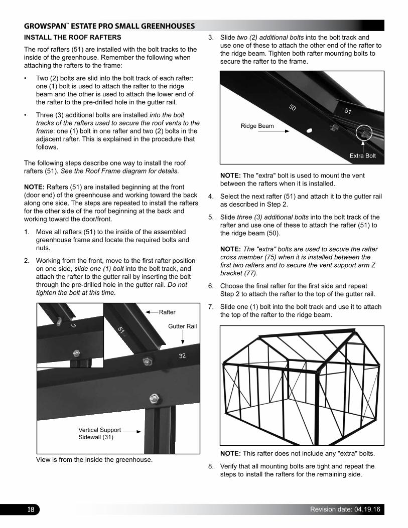
2. Working from the front, move to the first rafter position on one side, slide one (1) bolt into the bolt track, and attach the rafter to the gutter rail by inserting the bolt through the pre-drilled hole in the gutter rail. Do not tighten the bolt at this time.
View is from the inside the greenhouse.
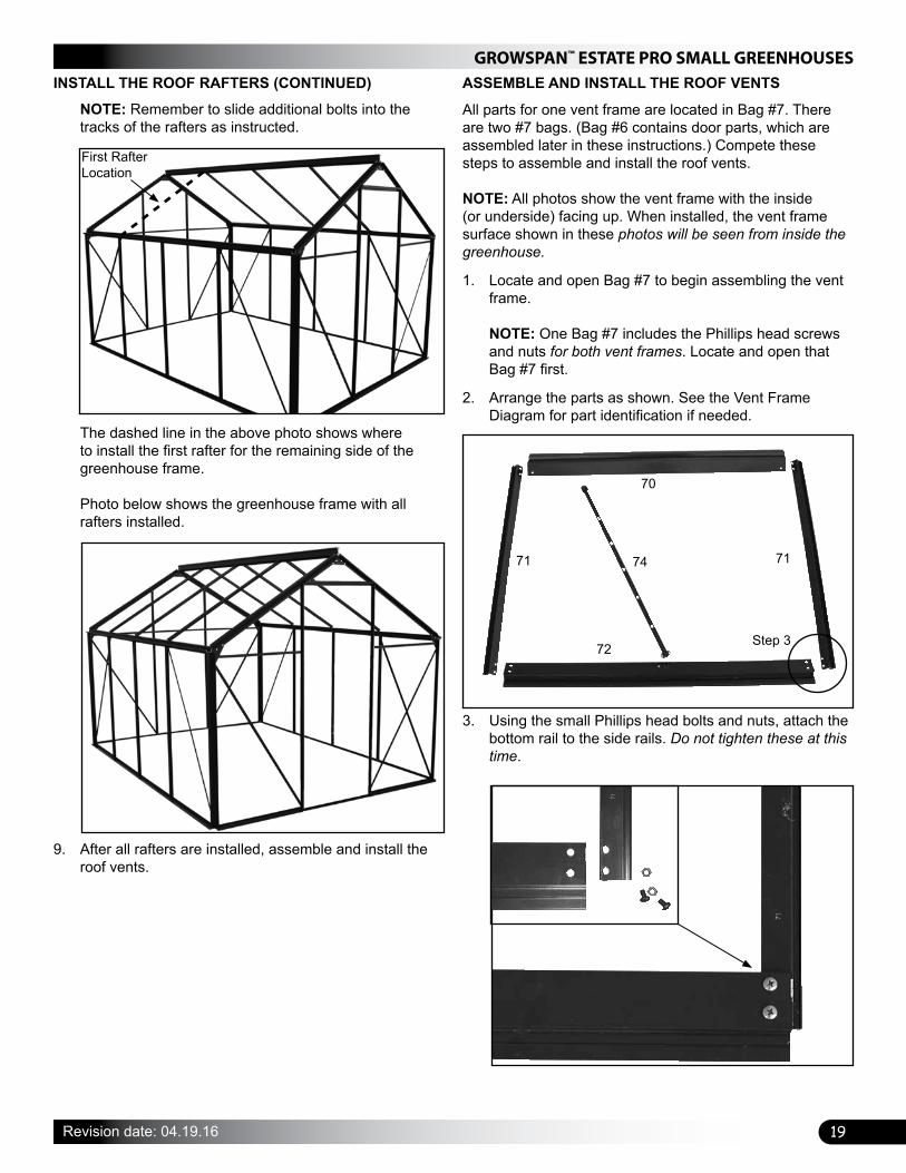
3. Slide two (2) additional bolts into the bolt track and use one of these to attach the other end of the rafter to the ridge beam. Tighten both rafter mounting bolts to secure the rafter to the frame.
NOTE: The "extra" bolt is used to mount the vent between the rafters when it is installed.
4. Select the next rafter (51) and attach it to the gutter rail as described in Step 2.
5. Slide three (3) additional bolts into the bolt track of the rafter and use one of these to attach the rafter (51) to the ridge beam (50). NOTE: The "extra" bolts are used to secure the rafter cross member (75) when it is installed between the first two rafters and to secure the vent support arm Z bracket (77).
6. Choose the final rafter for the first side and repeat Step 2 to attach the rafter to the top of the gutter rail.
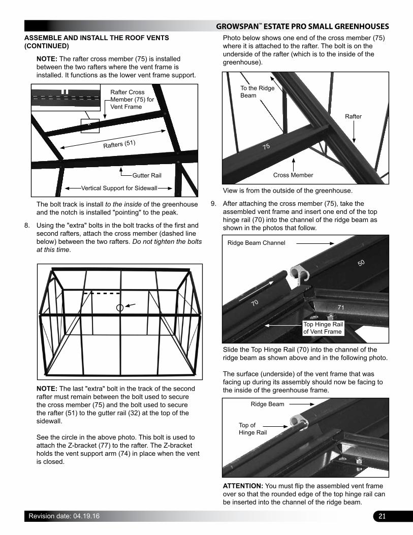
7. Slide one (1) bolt into the bolt track and use it to attach the top of the rafter to the ridge beam.
NOTE: This rafter does not include any "extra" bolts.
8. Verify that all mounting bolts are tight and repeat the steps to install the rafters for the remaining side.
Extra Bolt
Ridge Beam
Rafter
Vertical Support Sidewall (31)
Gutter Rail51
32
50 51
19
GROWSPAN™ ESTATE PRO SMALL GREENHOUSES
Revision date: 04.19.16
ASSEMBLE AND INSTALL THE ROOF VENTS
All parts for one vent frame are located in Bag #7. There are two #7 bags. (Bag #6 contains door parts, which are assembled later in these instructions.) Compete these steps to assemble and install the roof vents.
NOTE: All photos show the vent frame with the inside (or underside) facing up. When installed, the vent frame surface shown in these photos will be seen from inside the greenhouse.
1. Locate and open Bag #7 to begin assembling the vent frame. NOTE: One Bag #7 includes the Phillips head screws and nuts for both vent frames. Locate and open that Bag #7 first.
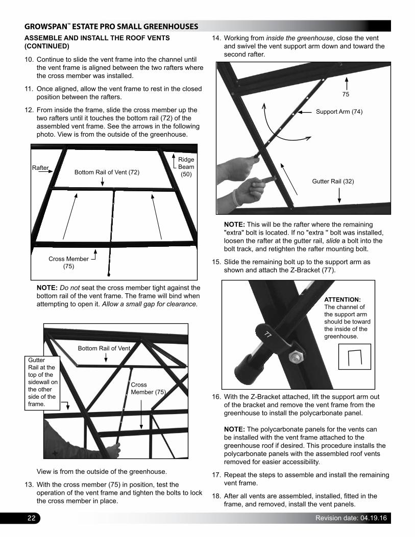
2. Arrange the parts as shown. See the Vent Frame Diagram for part identification if needed.
NOTE: Remember to slide additional bolts into the tracks of the rafters as instructed.
INSTALL THE ROOF RAFTERS (CONTINUED)
The dashed line in the above photo shows where to install the first rafter for the remaining side of the greenhouse frame. Photo below shows the greenhouse frame with all rafters installed.
First Rafter Location
9. After all rafters are installed, assemble and install the roof vents.
3. Using the small Phillips head bolts and nuts, attach the bottom rail to the side rails. Do not tighten these at this time.
70
72
71 7174
Step 3

GROWSPAN™ ESTATE PRO SMALL GREENHOUSES
20 Revision date: 04.19.16
5. Using a carpenter's square (or other means), verify that the assembled vent frame is square and tighten the bolts.
ASSEMBLE AND INSTALL THE ROOF VENTS (CONTINUED)
4. Next, attach the top hinge rail (70) to the side rails (71) using the Phillips head bolts and nuts.
6. Remove the bolt from the pre-assembled vent support arm (74), attach the swivel bracket to the bottom rail, and reattach the support arm to the bracket. If present, place the nylon washer between the swivel bracket and the vent frame. DO NOT OVERTIGHTEN THE NUT.
NOTE: The swivel bracket is attached to the bottom rail (72) using a small bolt and lock nut. The bracket must be allowed to swivel on the bottom rail (72) to ensure that the support arm functions as designed.
7. Once the vent frame is assembled and squared, locate the rafter cross member (75).
Photos show the end of the cross member and the bolt track which is installed to the inside of the greenhouse.
90°
90°
Bolt Track
75
75
21
GROWSPAN™ ESTATE PRO SMALL GREENHOUSES
Revision date: 04.19.16
NOTE: The rafter cross member (75) is installed between the two rafters where the vent frame is installed. It functions as the lower vent frame support.
ASSEMBLE AND INSTALL THE ROOF VENTS (CONTINUED)
The bolt track is install to the inside of the greenhouse and the notch is installed "pointing" to the peak.
8. Using the "extra" bolts in the bolt tracks of the first and second rafters, attach the cross member (dashed line below) between the two rafters. Do not tighten the bolts at this time.
NOTE: The last "extra" bolt in the track of the second rafter must remain between the bolt used to secure the cross member (75) and the bolt used to secure the rafter (51) to the gutter rail (32) at the top of the sidewall. See the circle in the above photo. This bolt is used to attach the Z-bracket (77) to the rafter. The Z-bracket holds the vent support arm (74) in place when the vent is closed.
Photo below shows one end of the cross member (75) where it is attached to the rafter. The bolt is on the underside of the rafter (which is to the inside of the greenhouse).
To the Ridge Beam
Rafter
Cross Member
View is from the outside of the greenhouse.
9. After attaching the cross member (75), take the assembled vent frame and insert one end of the top hinge rail (70) into the channel of the ridge beam as shown in the photos that follow.
Slide the Top Hinge Rail (70) into the channel of the ridge beam as shown above and in the following photo. The surface (underside) of the vent frame that was facing up during its assembly should now be facing to the inside of the greenhouse frame.
ATTENTION: You must flip the assembled vent frame over so that the rounded edge of the top hinge rail can be inserted into the channel of the ridge beam.
Ridge Beam
Top of Hinge Rail
Rafters (51)
Vertical Support for Sidewall
Gutter Rail
Rafter Cross Member (75) for Vent Frame
75
Ridge Beam Channel
Top Hinge Rail of Vent Frame
70
50
71
GROWSPAN™ ESTATE PRO SMALL GREENHOUSES
22 Revision date: 04.19.16
ASSEMBLE AND INSTALL THE ROOF VENTS (CONTINUED)
10. Continue to slide the vent frame into the channel until the vent frame is aligned between the two rafters where the cross member was installed.
11. Once aligned, allow the vent frame to rest in the closed position between the rafters.
12. From inside the frame, slide the cross member up the two rafters until it touches the bottom rail (72) of the assembled vent frame. See the arrows in the following photo. View is from the outside of the greenhouse.
Ridge Beam (50)
Cross Member (75)
RafterBottom Rail of Vent (72)
NOTE: Do not seat the cross member tight against the bottom rail of the vent frame. The frame will bind when attempting to open it. Allow a small gap for clearance.
View is from the outside of the greenhouse.
13. With the cross member (75) in position, test the operation of the vent frame and tighten the bolts to lock the cross member in place.
14. Working from inside the greenhouse, close the vent and swivel the vent support arm down and toward the second rafter.
NOTE: This will be the rafter where the remaining "extra" bolt is located. If no "extra '' bolt was installed, loosen the rafter at the gutter rail, slide a bolt into the bolt track, and retighten the rafter mounting bolt.
15. Slide the remaining bolt up to the support arm as shown and attach the Z-Bracket (77).
16. With the Z-Bracket attached, lift the support arm out of the bracket and remove the vent frame from the greenhouse to install the polycarbonate panel. NOTE: The polycarbonate panels for the vents can be installed with the vent frame attached to the greenhouse roof if desired. This procedure installs the polycarbonate panels with the assembled roof vents removed for easier accessibility.
17. Repeat the steps to assemble and install the remaining vent frame.
18. After all vents are assembled, installed, fitted in the frame, and removed, install the vent panels.
Bottom Rail of Vent
Cross Member (75)
Gutter Rail at the top of the sidewall on the other side of the frame.
77
ATTENTION: The channel of the support arm should be toward the inside of the greenhouse.
Support Arm (74)
75
Gutter Rail (32)
23
GROWSPAN™ ESTATE PRO SMALL GREENHOUSES
Revision date: 04.19.16
INSTALL THE POLYCARBONATE VENT PANELS
The steps below describe attaching the polycarbonate vent panels to the assembled vent frames. The panels are lettered for identification.
ATTENTION: Consult the polycarbonate panel installation information on Page 34 before you continue with this procedure.
The parts needed to complete the vent frame assembly include:
• Two (2) polycarbonate panels: Letter X
• U-profile (U700): four (4) sections
• Silicone and customer-supplied caulk gun NOTE: The plastic U-profile is precut. You do not have to cut any plastic profile. If it appears as though the plastic molding is the incorrect length, search through the remaining molding until you locate the correct length and continue with this procedure. Complete these steps:
ATTENTION: Install the polycarbonate panels with the UV-protected side to the outside of the greenhouse. If you remove the protective film before installing the panels, mark the panel in a lower corner using a piece of tape so that the panel is installed correctly.
1. Locate the first Panel X and two lengths of the U700 U-profile.
2. Carefully peal the protective film away from the edge on both sides of the panel. ATTENTION: To protect the panel, do not completely remove the protective film until you install the profile.
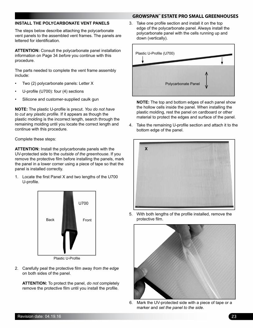
3. Take one profile section and install it on the top edge of the polycarbonate panel. Always install the polycarbonate panel with the cells running up and down (vertically).
NOTE: The top and bottom edges of each panel show the hollow cells inside the panel. When installing the plastic molding, rest the panel on cardboard or other material to protect the edges and surface of the panel.
4. Take the remaining U-profile section and attach it to the bottom edge of the panel.
5. With both lengths of the profile installed, remove the protective film.
X
6. Mark the UV-protected side with a piece of tape or a marker and set the panel to the side.
Plastic U-Profile
U700
Back Front
Plastic U-Profile (U700)
Polycarbonate Panel
GROWSPAN™ ESTATE PRO SMALL GREENHOUSES
24 Revision date: 04.19.16
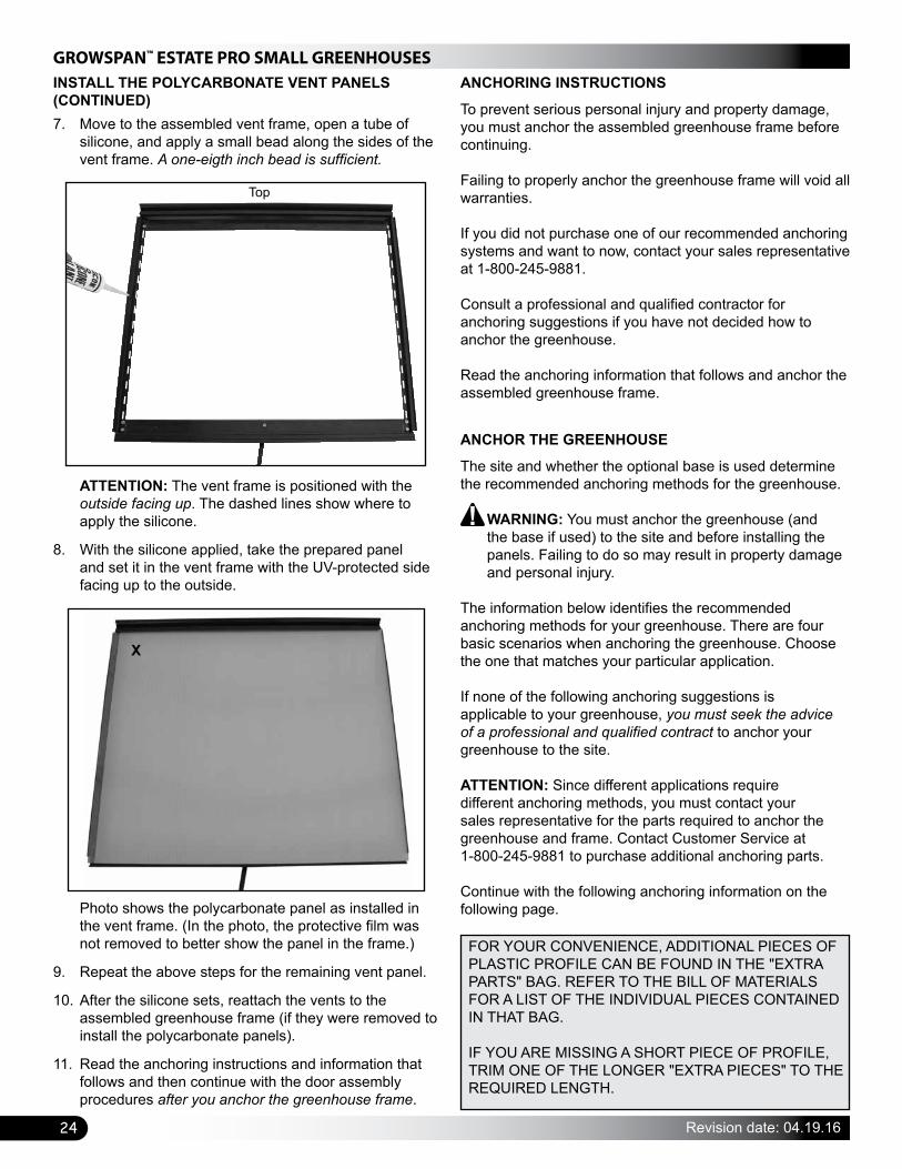
7. Move to the assembled vent frame, open a tube of silicone, and apply a small bead along the sides of the vent frame. A one-eigth inch bead is sufficient.
INSTALL THE POLYCARBONATE VENT PANELS (CONTINUED)
ATTENTION: The vent frame is positioned with the outside facing up. The dashed lines show where to apply the silicone.
8. With the silicone applied, take the prepared panel and set it in the vent frame with the UV-protected side facing up to the outside.
Photo shows the polycarbonate panel as installed in the vent frame. (In the photo, the protective film was not removed to better show the panel in the frame.)
9. Repeat the above steps for the remaining vent panel.
10. After the silicone sets, reattach the vents to the assembled greenhouse frame (if they were removed to install the polycarbonate panels).
11. Read the anchoring instructions and information that follows and then continue with the door assembly procedures after you anchor the greenhouse frame.
ANCHORING INSTRUCTIONS
To prevent serious personal injury and property damage, you must anchor the assembled greenhouse frame before continuing.
Failing to properly anchor the greenhouse frame will void all warranties.
If you did not purchase one of our recommended anchoring systems and want to now, contact your sales representative at 1-800-245-9881.
Consult a professional and qualified contractor for anchoring suggestions if you have not decided how to anchor the greenhouse. Read the anchoring information that follows and anchor the assembled greenhouse frame.
ANCHOR THE GREENHOUSE
The site and whether the optional base is used determine the recommended anchoring methods for the greenhouse.
WARNING: You must anchor the greenhouse (and the base if used) to the site and before installing the panels. Failing to do so may result in property damage and personal injury.
The information below identifies the recommended anchoring methods for your greenhouse. There are four basic scenarios when anchoring the greenhouse. Choose the one that matches your particular application. If none of the following anchoring suggestions is applicable to your greenhouse, you must seek the advice of a professional and qualified contract to anchor your greenhouse to the site.
ATTENTION: Since different applications require different anchoring methods, you must contact your sales representative for the parts required to anchor the greenhouse and frame. Contact Customer Service at 1-800-245-9881 to purchase additional anchoring parts.
Continue with the following anchoring information on the following page.
Top
X
FOR YOUR CONVENIENCE, ADDITIONAL PIECES OF PLASTIC PROFILE CAN BE FOUND IN THE "EXTRA PARTS" BAG. REFER TO THE BILL OF MATERIALS FOR A LIST OF THE INDIVIDUAL PIECES CONTAINED IN THAT BAG.
IF YOU ARE MISSING A SHORT PIECE OF PROFILE, TRIM ONE OF THE LONGER "EXTRA PIECES" TO THE REQUIRED LENGTH.
25
GROWSPAN™ ESTATE PRO SMALL GREENHOUSES
Revision date: 04.19.16
ANCHOR THE GREENHOUSE (CONTINUED)SCENARIO #1: Base Frame On Soil (or Gravel) Site
Ground posts are used to anchor the optional base to the site before the assembled greenhouse frame is set on the base.
1. After squaring the base and driving the support posts into the ground (see the Base Assembly instructions presented earlier in this packet), select the ground posts for the anchoring system.
2. Determine whether you want the ground posts on the inside or outside of the base assembly. NOTE: Ground posts are driven into the site near each corner of the assembled frame. You must order the ground posts. They are not included with the greenhouse.
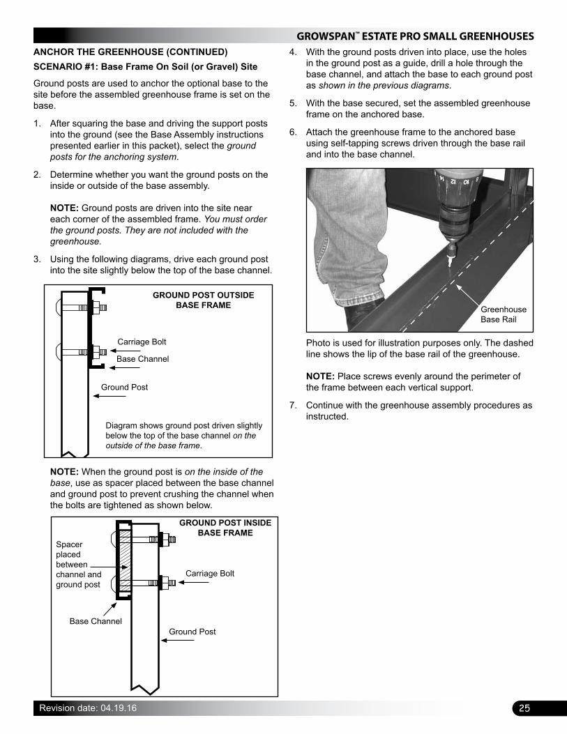
3. Using the following diagrams, drive each ground post into the site slightly below the top of the base channel.
NOTE: When the ground post is on the inside of the base, use as spacer placed between the base channel and ground post to prevent crushing the channel when the bolts are tightened as shown below.
GROUND POST OUTSIDE BASE FRAME
Base Channel
Carriage Bolt
Ground Post
Diagram shows ground post driven slightly below the top of the base channel on the outside of the base frame.
GROUND POST INSIDE BASE FRAME
Carriage Bolt
Ground Post
Spacer placed between channel and ground post
Base Channel
4. With the ground posts driven into place, use the holes in the ground post as a guide, drill a hole through the base channel, and attach the base to each ground post as shown in the previous diagrams.
5. With the base secured, set the assembled greenhouse frame on the anchored base.
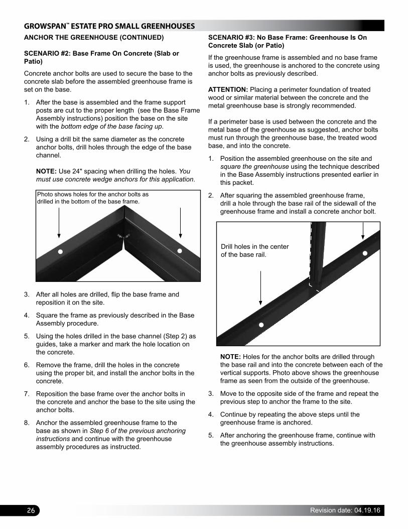
6. Attach the greenhouse frame to the anchored base using self-tapping screws driven through the base rail and into the base channel.
Greenhouse Base Rail
Photo is used for illustration purposes only. The dashed line shows the lip of the base rail of the greenhouse. NOTE: Place screws evenly around the perimeter of the frame between each vertical support.
7. Continue with the greenhouse assembly procedures as instructed.
GROWSPAN™ ESTATE PRO SMALL GREENHOUSES
26 Revision date: 04.19.16
SCENARIO #2: Base Frame On Concrete (Slab or Patio)
Concrete anchor bolts are used to secure the base to the concrete slab before the assembled greenhouse frame is set on the base.
1. After the base is assembled and the frame support posts are cut to the proper length (see the Base Frame Assembly instructions) position the base on the site with the bottom edge of the base facing up.
2. Using a drill bit the same diameter as the concrete anchor bolts, drill holes through the edge of the base channel. NOTE: Use 24" spacing when drilling the holes. You must use concrete wedge anchors for this application.
SCENARIO #3: No Base Frame: Greenhouse Is On Concrete Slab (or Patio)
If the greenhouse frame is assembled and no base frame is used, the greenhouse is anchored to the concrete using anchor bolts as previously described.
ATTENTION: Placing a perimeter foundation of treated wood or similar material between the concrete and the metal greenhouse base is strongly recommended.
If a perimeter base is used between the concrete and the metal base of the greenhouse as suggested, anchor bolts must run through the greenhouse base, the treated wood base, and into the concrete.
1. Position the assembled greenhouse on the site and square the greenhouse using the technique described in the Base Assembly instructions presented earlier in this packet.
2. After squaring the assembled greenhouse frame, drill a hole through the base rail of the sidewall of the greenhouse frame and install a concrete anchor bolt.
ANCHOR THE GREENHOUSE (CONTINUED)
3. After all holes are drilled, flip the base frame and reposition it on the site.
4. Square the frame as previously described in the Base Assembly procedure.
5. Using the holes drilled in the base channel (Step 2) as guides, take a marker and mark the hole location on the concrete.
6. Remove the frame, drill the holes in the concrete using the proper bit, and install the anchor bolts in the concrete.
7. Reposition the base frame over the anchor bolts in the concrete and anchor the base to the site using the anchor bolts.
8. Anchor the assembled greenhouse frame to the base as shown in Step 6 of the previous anchoring instructions and continue with the greenhouse assembly procedures as instructed.
NOTE: Holes for the anchor bolts are drilled through the base rail and into the concrete between each of the vertical supports. Photo above shows the greenhouse frame as seen from the outside of the greenhouse.
3. Move to the opposite side of the frame and repeat the previous step to anchor the frame to the site.
4. Continue by repeating the above steps until the greenhouse frame is anchored.
5. After anchoring the greenhouse frame, continue with the greenhouse assembly instructions.
Photo shows holes for the anchor bolts as drilled in the bottom of the base frame.
Drill holes in the center of the base rail.
27
GROWSPAN™ ESTATE PRO SMALL GREENHOUSES
Revision date: 04.19.16
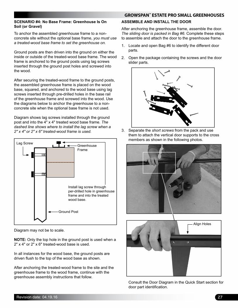
SCENARIO #4: No Base Frame: Greenhouse Is On Soil (or Gravel)
To anchor the assembled greenhouse frame to a non-concrete site without the optional base frame, you must use a treated-wood base frame to set the greenhouse on.
Ground posts are then driven into the ground on either the inside or outside of the treated-wood base frame. The wood frame is anchored to the ground posts using lag screws inserted through the ground post holes and screwed into the wood.
After securing the treated-wood frame to the ground posts, the assembled greenhouse frame is placed on the wood base, squared, and anchored to the wood base using lag screws inserted through pre-drilled holes in the base rail of the greenhouse frame and screwed into the wood. Use the diagrams below to anchor the greenhouse to a non-concrete site when the optional base frame is not used. Diagram shows lag screws installed through the ground post and into the 4" x 4" treated wood base frame. The dashed line shows where to install the lag screw when a2" x 4" or 2" x 6" treated-wood frame is used.
Diagram may not be to scale. NOTE: Only the top hole in the ground post is used when a 2" x 4" or 2" x 6" treated-wood base is used.
In all instances for the wood base, the ground posts are driven flush to the top of the wood base as shown. After anchoring the treated-wood frame to the site and the greenhouse frame to the wood frame, continue with the greenhouse assembly instructions that follow.
Lag Screw
Install lag screw through per-drilled hole in greenhouse frame and into the treated wood base.
Greenhouse Frame
Ground Post
ASSEMBLE AND INSTALL THE DOOR
After anchoring the greenhouse frame, assemble the door. The sliding door is packed in Bag #6. Complete these steps to assemble and attach the door to the greenhouse frame.
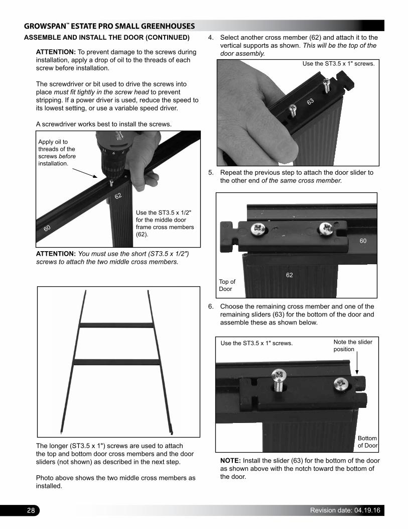
1. Locate and open Bag #6 to identify the different door parts.
2. Open the package containing the screws and the door slider parts.
3. Separate the short screws from the pack and use them to attach the vertical door supports to the cross members as shown in the following photos.
Align Holes
Consult the Door Diagram in the Quick Start section for door part identification.
GROWSPAN™ ESTATE PRO SMALL GREENHOUSES
28 Revision date: 04.19.16
ATTENTION: To prevent damage to the screws during installation, apply a drop of oil to the threads of each screw before installation. The screwdriver or bit used to drive the screws into place must fit tightly in the screw head to prevent stripping. If a power driver is used, reduce the speed to its lowest setting, or use a variable speed driver. A screwdriver works best to install the screws.
ASSEMBLE AND INSTALL THE DOOR (CONTINUED)
ATTENTION: You must use the short (ST3.5 x 1/2") screws to attach the two middle cross members.
The longer (ST3.5 x 1") screws are used to attach the top and bottom door cross members and the door sliders (not shown) as described in the next step. Photo above shows the two middle cross members as installed.
4. Select another cross member (62) and attach it to the vertical supports as shown. This will be the top of the door assembly.
5. Repeat the previous step to attach the door slider to the other end of the same cross member.
6. Choose the remaining cross member and one of the remaining sliders (63) for the bottom of the door and assemble these as shown below.
NOTE: Install the slider (63) for the bottom of the door as shown above with the notch toward the bottom of the door.
Apply oil to threads of the screws before installation.
Use the ST3.5 x 1/2" for the middle door frame cross members (62).
62
60
Use the ST3.5 x 1" screws.
63
Top of Door
60
62
Note the slider position
Bottom of Door
Use the ST3.5 x 1" screws.

29
GROWSPAN™ ESTATE PRO SMALL GREENHOUSES
Revision date: 04.19.16
7. Repeat the previous step to attach the remaining door slider and cross member to the door frame to complete the door frame assembly.
8. After assembling the door frame, install the polycarbonate panels for the door.
ASSEMBLE AND INSTALL THE DOOR (CONTINUED)
INSTALL THE POLYCARBONATE DOOR PANELS
The steps to prepare and install the polycarbonate panels for the doors are similar to those described in the vent panel installation procedure. The door panels are lettered for identification. Consult the panel diagrams in the Quick Start section for panel identification and locations. NOTE: The protective film has not been removed in the following photos. You must remove the film as instructed during the assembly process. Consult the polycarbonate installation information on Page 34 before you begin. The parts needed to complete the door frame assemblyinclude:
• Two (2) Y1 panels (top/bottom) and one (1) Y2 panel (center).
• Six (6) lengths of plastic U-profile (U622)
• Silicone and customer-supplied caulk gun
NOTE: The plastic U-profile sections are precut and are as long as the polycarbonate panel is wide. You do not have to cut any plastic molding. If it appears as though the plastic molding is the incorrect length, search through the remaining molding until you locate the correct length for the panels. Complete these steps: ATTENTION: Install the polycarbonate panels with the UV-protected side to the outside of the greenhouse. If you remove the protective film before installing the panels, mark the panel in a lower corner so that the panel is installed correctly.
1. Locate the Y2 panel and two lengths of the plastic U622 profile.
2. Carefully peal the protective film away from the edge on both sides of the panel. Do not completely remove the protective film until the profile sections are installed.
3. Take one U622 profile section and install it on the top edge of the polycarbonate panel.
NOTE: The top and bottom edges of each panel show the hollow cells inside the panel. When installing the plastic molding, rest the panel on cardboard or other material to protect the edges and surface of the panel.
Plastic U-Profile
Polycarbonate Panel
Plastic U-Profile
Top

GROWSPAN™ ESTATE PRO SMALL GREENHOUSES
30 Revision date: 04.19.16
INSTALL THE POLYCARBONATE DOOR PANELS (CONTINUED)
4. Take the remaining U-profile section and attach it to the bottom edge of the panel.
5. With both lengths of the plastic U-profile installed on the panel, peal the protective film from the panel.
6. Mark the UV-protected side with a piece of tape or a marker and remember that it is installed to the outside.
ATTENTION: Photo shows the back or inside surface of the door. Silicone is applied along the sides of the frame to keep the panel secured. Silicone alone secures the panels to the door frame.
9. With the silicone applied, take the prepared panel and press it firmly into the door frame. Verify that the UV-protected side of the panel is installed so that it faces toward the outside when the door is attached to the greenhouse frame.
7. Place the assembled door frame face down on a piece of cardboard to protect the panel surfaces.
8. Apply a small bead of silicone (1/8") along the sides of the door frame in the areas shown by the white dashed line in the photo below.
Dashed lines above shows the location of the silicone applied before the panel is pressed into place.
10. Repeat the previous steps to attach the remaining polycarbonate panels to the door frame.
Backside of the Panel
U622 Profile
U622 Profile

31
GROWSPAN™ ESTATE PRO SMALL GREENHOUSES
Revision date: 04.19.16
INSTALL THE POLYCARBONATE DOOR PANELS (CONTINUED)
Photo shows the door and installed panels as seen from the outside. The protective film was not removed to better show the panels.
Y1
Y2
Y1
11. After setting the panels in place, install the door weather-stripping (69) in the locations shown by the dashed lines in the photo below. View shows the outside of the door looking at its top.
12. After the silicone sets, attach the door track and bracket to the assembled frame.
NOTE: At this time, you can continue with the polycarbonate panel installation steps while the silicone sets and return to install the door track last, or you can continue with the door track and bracket installation that follows.
INSTALL THE DOOR TRACK AND BRACKET
The door track (19-3) and track support arm (64) are attached to the door end of the frame. Complete the steps below to install these items:
1. Locate the door track (19-3).
2. Tilt the track so the bolt track is facing up and slide two (2) bolts into the track.
3. Slide the track onto the assembled door as shown.
Polycarbonate panels have been removed for clarity.
Install Weather-Stripping
Top of the Door
UV-Protected Side
19-3
Top of the Door
GROWSPAN™ ESTATE PRO SMALL GREENHOUSES
32 Revision date: 04.19.16
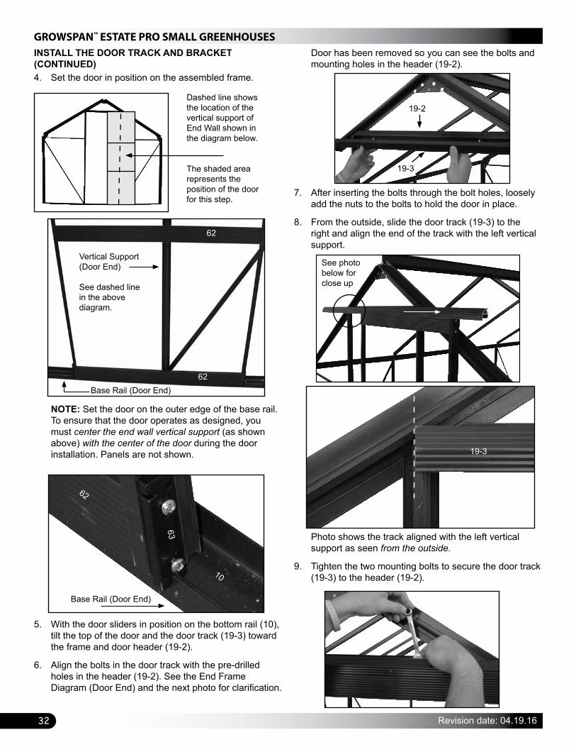
4. Set the door in position on the assembled frame.
INSTALL THE DOOR TRACK AND BRACKET (CONTINUED)
NOTE: Set the door on the outer edge of the base rail. To ensure that the door operates as designed, you must center the end wall vertical support (as shown above) with the center of the door during the door installation. Panels are not shown.
Base Rail (Door End)
Vertical Support (Door End)
See dashed line in the above diagram.
5. With the door sliders in position on the bottom rail (10), tilt the top of the door and the door track (19-3) toward the frame and door header (19-2).
6. Align the bolts in the door track with the pre-drilled holes in the header (19-2). See the End Frame Diagram (Door End) and the next photo for clarification.
Door has been removed so you can see the bolts and mounting holes in the header (19-2).
Photo shows the track aligned with the left vertical support as seen from the outside.
9. Tighten the two mounting bolts to secure the door track (19-3) to the header (19-2).
Dashed line shows the location of the vertical support of End Wall shown in the diagram below.
The shaded area represents the position of the door for this step.
Base Rail (Door End)
10
63
7. After inserting the bolts through the bolt holes, loosely add the nuts to the bolts to hold the door in place.
8. From the outside, slide the door track (19-3) to the right and align the end of the track with the left vertical support.
19-3
19-2
19-3
62
62
62
See photo below for close up

33
GROWSPAN™ ESTATE PRO SMALL GREENHOUSES
Revision date: 04.19.16
INSTALL THE GUTTER RAIL ENDS
Before installing the remaining polycarbonate panels, install the plastic gutter rail ends as shown below.
1. Locate one plastic gutter rail end and one gutter downspout end and install these on the desired gutter rail ends as shown.
10. Move to the right (or free) end of the track (19-3), slide a bolt into the bolt track, and loosely attach the top of the track support bracket (64) to the door track.
INSTALL THE DOOR TRACK AND BRACKET (CONTINUED)
View is from the back of the door track (19-3).
11. Insert a bolt through the pre-drilled hole in the upper support of the end wall and attach the lower end of the track support bracket as shown.
12. Verify that the bracket is straight and tighten the upper and lower mounting bolts to secure the bracket and door track to the frame.
UV-protected side of each door panel is to the outside as shown. View above is from the outside.
13. Check the door operation and adjust the sliders (63) if needed.
14. Continue by installing the gutter rail ends.
2. Repeat the steps to install the remaining gutter rail ends.
3. Continue with installing the side, end, and roof polycarbonate panels.
NOTE: The angled bracket (68) shown above and on the bill of materials for Bag #6 may come attached to the track support (64).
Upper Support
Track Support (64) with attached bracket (68)
90°
Upper Door Panel
64
19-3
GROWSPAN™ ESTATE PRO SMALL GREENHOUSES
34 Revision date: 04.19.16
INSTALL THE POLYCARBONATE PANELS
The remaining panels can be installed in any order. For these instructions, the sidewall panels are installed next, followed by the end panels, and finally the roof panels. Required Plastic Molding
The following plastic molding is needed to complete the installation of all remaining polycarbonate panels:
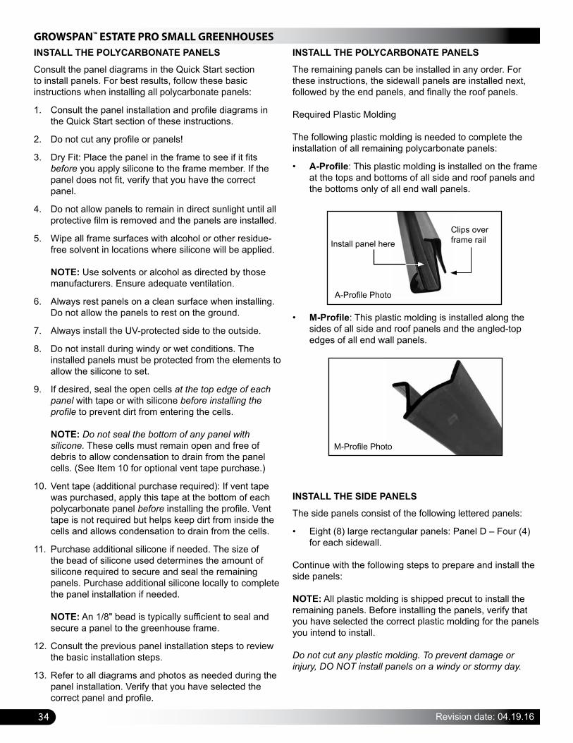
• A-Profile: This plastic molding is installed on the frame at the tops and bottoms of all side and roof panels and the bottoms only of all end wall panels.
• M-Profile: This plastic molding is installed along the sides of all side and roof panels and the angled-top edges of all end wall panels.
M-Profile Photo
Install panel hereClips over frame rail
A-Profile Photo
INSTALL THE SIDE PANELS
The side panels consist of the following lettered panels:
• Eight (8) large rectangular panels: Panel D – Four (4) for each sidewall.
Continue with the following steps to prepare and install the side panels:
NOTE: All plastic molding is shipped precut to install the remaining panels. Before installing the panels, verify that you have selected the correct plastic molding for the panels you intend to install. Do not cut any plastic molding. To prevent damage or injury, DO NOT install panels on a windy or stormy day.
INSTALL THE POLYCARBONATE PANELS
Consult the panel diagrams in the Quick Start section to install panels. For best results, follow these basic instructions when installing all polycarbonate panels:
1. Consult the panel installation and profile diagrams in the Quick Start section of these instructions.
2. Do not cut any profile or panels!
3. Dry Fit: Place the panel in the frame to see if it fits before you apply silicone to the frame member. If the panel does not fit, verify that you have the correct panel.
4. Do not allow panels to remain in direct sunlight until all protective film is removed and the panels are installed.
5. Wipe all frame surfaces with alcohol or other residue-free solvent in locations where silicone will be applied. NOTE: Use solvents or alcohol as directed by those manufacturers. Ensure adequate ventilation.
6. Always rest panels on a clean surface when installing. Do not allow the panels to rest on the ground.
7. Always install the UV-protected side to the outside.
8. Do not install during windy or wet conditions. The installed panels must be protected from the elements to allow the silicone to set.
9. If desired, seal the open cells at the top edge of each panel with tape or with silicone before installing the profile to prevent dirt from entering the cells. NOTE: Do not seal the bottom of any panel with silicone. These cells must remain open and free of debris to allow condensation to drain from the panel cells. (See Item 10 for optional vent tape purchase.)
10. Vent tape (additional purchase required): If vent tape was purchased, apply this tape at the bottom of each polycarbonate panel before installing the profile. Vent tape is not required but helps keep dirt from inside the cells and allows condensation to drain from the cells.
11. Purchase additional silicone if needed. The size of the bead of silicone used determines the amount of silicone required to secure and seal the remaining panels. Purchase additional silicone locally to complete the panel installation if needed. NOTE: An 1/8" bead is typically sufficient to seal and secure a panel to the greenhouse frame.
12. Consult the previous panel installation steps to review the basic installation steps.
13. Refer to all diagrams and photos as needed during the panel installation. Verify that you have selected the correct panel and profile.

35
GROWSPAN™ ESTATE PRO SMALL GREENHOUSES
Revision date: 04.19.16
1. Locate one, precut length of A-profile molding and install it on the base rail of the sidewall.
View is from the outside of the greenhouse.
A-profile as installed on the base rail of the sidewall.
2. Install a second length of A-profile on the underside of the gutter rail directly above the first A-profile.
3. Select the first Panel D and remove the protective film. REMEMBER: Mark the UV-protected side and install this surface to the outside of the greenhouse. The UV-protected side is always installed facing to the outside.
Base Rail (sidewall)
A-Profile
Gutter Rail
A-Profile
Rafter (51)
4. Referring to the notes on Page 34, prepare the panel and clean the surface of the sidewall supports (31), and from the outside apply a bead of silicone along each support. NOTE: The dashed lines in the photo below shows where to apply the silicone BEFORE installing the panel. Refer to the vent and door panel installation steps if needed when applying the silicone.
5. After applying the silicone to the sidewall supports (31) and working from the outside of the frame, insert the bottom of the panel into the A-profile attached to the base rail of the sidewall.
6. Without disturbing the silicone, slightly bow the panel middle outward and insert the top into the channel of the A-profile installed on the underside of the gutter rail. NOTE: The protective film (shown above) has been left on the panel for illustration purposes only. Actual panel is installed without the film.
7. Firmly press the installed panel against the silicone to seat it into position. NOTE: Some silicone may squeeze out between the panel and the frame on the inside of the greenhouse. Use your finger or putty knife to spread the silicone evenly along the edge of the panel if desired.
INSTALL THE SIDE PANELS (CONTINUED)
A-Profile
As viewed from the outside.
30
30
31
32
Outside of the panel.

GROWSPAN™ ESTATE PRO SMALL GREENHOUSES
36 Revision date: 04.19.16
INSTALL THE SIDE PANELS (CONTINUED)
Profile is install on the outside of the panel.
9. Repeat the step to install the remaining section of M-profile for the panel.
Photo below shows a different panel. It is used to show how the M-profile snaps into the channel of the vertical support.
Panel
Gutter Rail
Vertical Support
M-Profile
32
31
10. After securing the first sidewall polycarbonate panel in the frame, repeat the steps to install all remaining sidewall panels (Panel D).
11. After all sidewall panels are in place, install the end wall panels and the roof panels. ATTENTION: Consult the End Wall and Roof Panel and Profile diagrams in the QuickStart section of these instructions for panel and profile identifications.
Snap profile into the channel of the vertical support.
8. With the panel in position, take a section of M-profile and snap it into place along the sidewall vertical support on the outside of the panel.
M-Profile
NOTE: Consult the Sidewall Panel and Profile diagram in the QuickStart section of these instructions for the M-profile installation location.
EXTRA PARTS PROVIDED FOR GREENHOUSE
ATTENTION: TO AVOID TWISTING OFF OR DAMAGING THE FASTENERS, DO NOT OVERTIGHTEN.
FOR YOUR CONVENIENCE, ADDITIONAL FASTENERS AND PLASTIC MOLDING CAN BE FOUND IN THE "EXTRA PARTS" BAG OR BOX.
REFER TO THE BILL OF MATERIALS FOR A LIST OF THE FASTENERS AND MOLDING CONTAINED IN THAT BAG OR BOX.
The plastic profile can be trimmed to the required length if a piece is misplaced or damaged during installation.
IMPORTANT: Consult the "extra parts" for items you need before contacting customer service to request a replacement for damaged or missing parts or fasteners.

37
GROWSPAN™ ESTATE PRO SMALL GREENHOUSES
Revision date: 04.19.16
INSTALL THE END WALL PANELS
The end wall panels are installed and secured in the same manner as the sidewall panels with the following exception: The A-profile is installed at the bottom only; the M-profile is installed along each side and angled edge.
For the door end of the greenhouse, locate these panels: Two (2) large, angled panels: Panel A and one (1) triangular panel: Panel C – This panel is installed above the door opening.
For the non-door end of the greenhouse, locate these panels: Two (2) large, angled panels: Panel A and one (1) center panel: Panel B.
NOTE: The angled A panels are identical for the end walls. When installing the panels, select the panel that allows you to install the UV-protected side to the outside of the greenhouse. Consult the panel diagrams. Silicone Application: Silicone is applied from the outside along the lip of each vertical support before the panels are pressed into place. See the dashed lines on the panel diagrams in the Quick Start section.
NOTE: A-Profile Location: See dashed lines above (and below). See the panel diagrams for M-profile details.
See the panel diagrams for all profile locations and identification.
Panel A and Panel B Locations: Non-Door End Frame
A A
B
INSTALL THE ROOF PANELS
Install and secure the roof panels in the same manner as the previous panels. Roof panels consist of the following:
• Six (6) long, rectangular panels: Panel E
• Two (2) short panels: Panel F – This panel is installed below the roof vent.
ATTENTION: Remember to install all panels with theUV-protected surface to the outside.
Photo shows the roof vent with the installed panel (PanelX) and the adjacent, lower roof panel (Panel F). The dashed line (above) shows the location of the A-profile. The M-profile is installed along the sides of the panels. NOTE: Vent Panel X was installed earlier in these instructions. It is secured using silicone only.
Diagram shows Panel (E) for the roof and Panel D for the sidewall. Dashed lines (above) represent where to apply silicone before setting the roof panels into place. Silicone is applied along the lip of each roof rafter before setting the prepared panel into place and securing it with the M-profile sections.
Panel A and Panel C Locations: Door End Frame
M-ProfilePanel C:Above door opening
AA
E
D
Roof Vent
F
X
CONSULT THE PANEL DIAGRAMS
GROWSPAN™ ESTATE PRO SMALL GREENHOUSES
38 Revision date: 04.19.16
Space below is reserved for customer notes.CARE AND MAINTENANCE
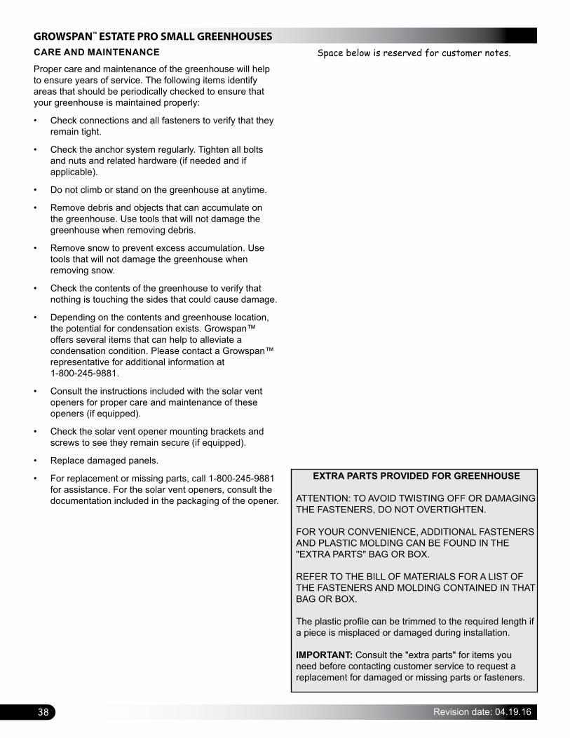
Proper care and maintenance of the greenhouse will help to ensure years of service. The following items identify areas that should be periodically checked to ensure that your greenhouse is maintained properly:
• Check connections and all fasteners to verify that they remain tight.
• Check the anchor system regularly. Tighten all bolts and nuts and related hardware (if needed and if applicable).
• Do not climb or stand on the greenhouse at anytime.
• Remove debris and objects that can accumulate on the greenhouse. Use tools that will not damage the greenhouse when removing debris.
• Remove snow to prevent excess accumulation. Use tools that will not damage the greenhouse when removing snow.
• Check the contents of the greenhouse to verify that nothing is touching the sides that could cause damage.
• Depending on the contents and greenhouse location, the potential for condensation exists. Growspan™ offers several items that can help to alleviate a condensation condition. Please contact a Growspan™ representative for additional information at 1-800-245-9881.
• Consult the instructions included with the solar vent openers for proper care and maintenance of these openers (if equipped).
• Check the solar vent opener mounting brackets and screws to see they remain secure (if equipped).
• Replace damaged panels.
• For replacement or missing parts, call 1-800-245-9881 for assistance. For the solar vent openers, consult the documentation included in the packaging of the opener.
EXTRA PARTS PROVIDED FOR GREENHOUSE
ATTENTION: TO AVOID TWISTING OFF OR DAMAGING THE FASTENERS, DO NOT OVERTIGHTEN.
FOR YOUR CONVENIENCE, ADDITIONAL FASTENERS AND PLASTIC MOLDING CAN BE FOUND IN THE "EXTRA PARTS" BAG OR BOX.
REFER TO THE BILL OF MATERIALS FOR A LIST OF THE FASTENERS AND MOLDING CONTAINED IN THAT BAG OR BOX.
The plastic profile can be trimmed to the required length if a piece is misplaced or damaged during installation.
IMPORTANT: Consult the "extra parts" for items you need before contacting customer service to request a replacement for damaged or missing parts or fasteners.
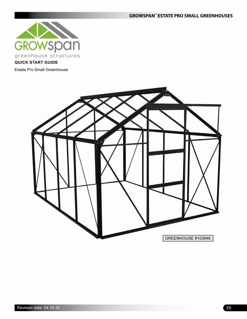
39
GROWSPAN™ ESTATE PRO SMALL GREENHOUSES
Revision date: 04.19.16
QUICK START GUIDE
Estate Pro Small Greenhouse
GREENHOUSE #103846
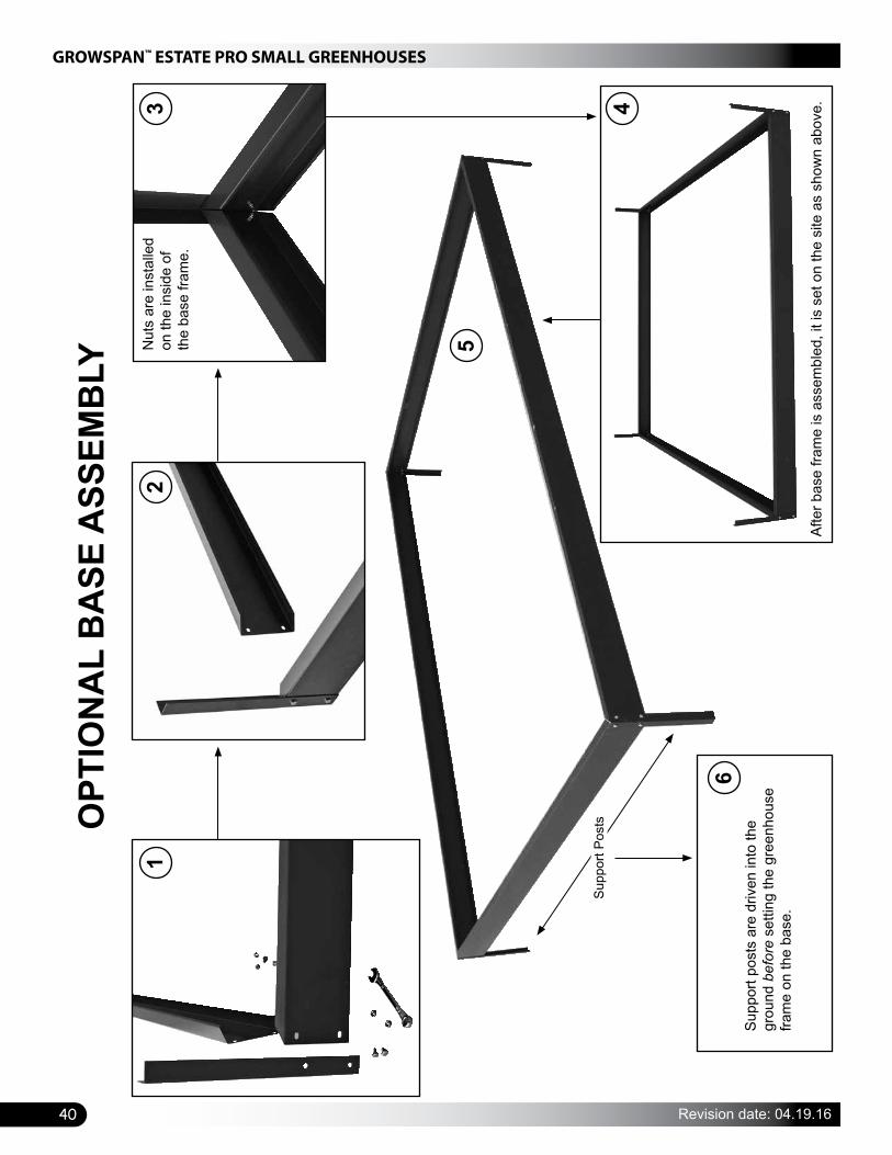
GROWSPAN™ ESTATE PRO SMALL GREENHOUSES
40 Revision date: 04.19.16
OPT
ION
AL
BA
SE A
SSEM
BLY
Supp
ort P
osts
Afte
r bas
e fra
me
is a
ssem
bled
, it i
s se
t on
the
site
as
show
n ab
ove.
Supp
ort p
osts
are
driv
en in
to th
e gr
ound
bef
ore
setti
ng th
e gr
eenh
ouse
fra
me
on th
e ba
se.
12
3 4
6
Nut
s ar
e in
stal
led
on th
e in
side
of
the
base
fram
e.
5
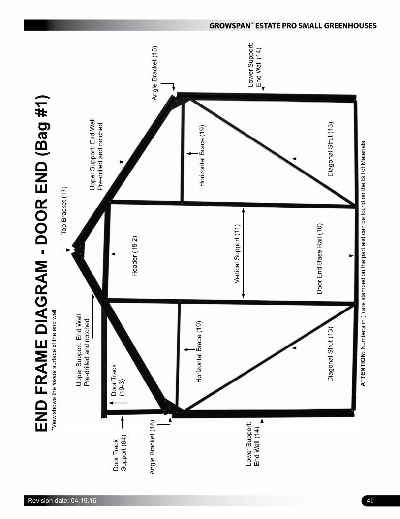
41
GROWSPAN™ ESTATE PRO SMALL GREENHOUSES
Revision date: 04.19.16
END
FR
AM
E D
IAG
RA
M -
DO
OR
EN
D (B
ag #
1)*V
iew
sho
ws
the
insi
de s
urfa
ce o
f the
end
wal
l.
Hea
der (
19-2
)Top
Brac
ket (
17) Upp
er S
uppo
rt: E
nd W
all
Pre-
drille
d an
d no
tche
d
Angl
e Br
acke
t (18
)
Low
er S
uppo
rt:
End
Wal
l (14
)
Dia
gona
l Stru
t (13
)D
iago
nal S
trut (
13)
Doo
r End
Bas
e R
ail (
10)
Verti
cal S
uppo
rt (1
1)
Angl
e Br
acke
t (18
)
Upp
er S
uppo
rt: E
nd W
all
Pre-
drille
d an
d no
tche
d
Hor
izon
tal B
race
(19)
Hor
izon
tal B
race
(19)
Low
er S
uppo
rt:
End
Wal
l (14
)
ATTE
NTI
ON
: Num
bers
in (
) are
sta
mpe
d on
the
part
and
can
be fo
und
on th
e Bi
ll of
Mat
eria
ls.
Doo
r Tra
ck
(19-
3)D
oor T
rack
Su
ppor
t (64
)

GROWSPAN™ ESTATE PRO SMALL GREENHOUSES
42 Revision date: 04.19.16
END
FR
AM
E D
IAG
RA
M -
NO
DO
OR
(Bag
#2)
Upp
er S
uppo
rt: E
nd W
all
Pre-
drille
d an
d no
tche
d
Upp
er S
uppo
rt: E
nd W
all
Pre-
drille
d an
d no
tche
d
*Vie
w s
how
s th
e in
side
sur
face
of t
he e
nd w
all.
ATTE
NTI
ON
: Num
bers
in (
) are
sta
mpe
d on
the
part
and
can
be fo
und
on th
e Bi
ll of
Mat
eria
ls w
ith th
e sh
ipm
ent.
The
parts
that
are
not
iden
tifie
d ab
ove
have
the
sam
e nu
mbe
rs a
s th
ose
show
n on
the
End
Fram
e D
iagr
am: D
oor E
nd (B
ag #
1).
Hor
izon
tal B
race
(29)
Verti
cal S
uppo
rt (2
2)Ve
rtica
l Sup
port
(21)
Non
-Doo
r End
Ba
se R
ail (
20)
Dia
gona
l Stru
t (13
)
Low
er S
uppo
rt:
End
Wal
l (14
)
Low
er S
uppo
rt:
End
Wal
l (14
)
Dia
gona
l Stru
t (13
)

43
GROWSPAN™ ESTATE PRO SMALL GREENHOUSES
Revision date: 04.19.16
SID
EWA
LL F
RA
ME
DIA
GR
AM
Dia
gona
l Stru
t: Si
de W
all (
33)
Base
Rai
l: Si
de W
all (
30)
Verti
cal S
uppo
rt:
Side
Wal
l (31
)
Gut
ter R
ail (
32)
NO
TE: T
he s
idew
all d
iagr
am s
how
s th
e as
sem
bly
as s
een
from
the
insi
de o
f the
gr
eenh
ouse
. The
das
hed
line
iden
tifie
s th
e bo
lt tra
ck in
eac
h ve
rtica
l sup
port.
ATTE
NTI
ON
: The
gut
ter r
ail p
hoto
(lef
t) sh
ows
the
outs
ide
view
of t
he g
utte
r rai
l.Th
e di
agra
m b
elow
sho
ws
the
back
or
insi
de s
urfa
ce o
f the
gut
ter r
ail a
s th
e si
dew
all i
s as
sem
bled
on
a fla
t sur
face
.
REM
EMB
ER: V
ertic
al s
uppo
rts a
re a
lway
s in
stal
led
with
the
bolt
track
to th
e in
side
of
your
gre
enho
use.
32
Gut
ter r
ail a
s se
en fr
om th
e ou
tsid
e.
Dia
gona
l Stru
t (3
3)

GROWSPAN™ ESTATE PRO SMALL GREENHOUSES
44 Revision date: 04.19.16
ROOF FRAME DIAGRAM - 103846
Ridge Beam
Gutter RailATTENTION: The dots (left) and circles (below) identify where to install the additional bolts during the roof assembly. These bolts are used to attach the vent frames and bracket for the support arm.
Vents can be installed between any of the roof rafters. This example shows the vent installed between the first and second rafters.
Details of the shaded area (left) are shown in the line diagram below.
FRONT (DOOR END)
Ridge Beam
Gutter Rail
51 5151
X X X
X X X
X shows the rafter mounting bolt locations.
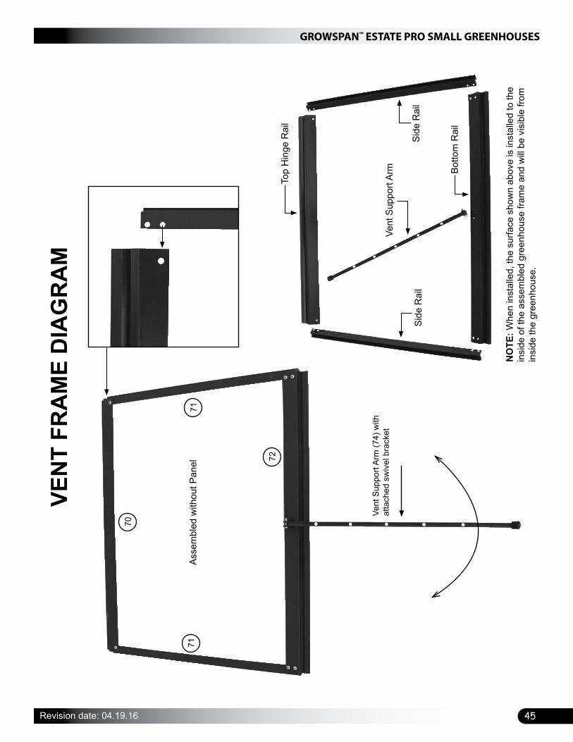
45
GROWSPAN™ ESTATE PRO SMALL GREENHOUSES
Revision date: 04.19.16
VEN
T FR
AM
E D
IAG
RA
M
70
71
Vent
Sup
port
Arm
(74)
with
at
tach
ed s
wiv
el b
rack
et
NO
TE: W
hen
inst
alle
d, th
e su
rface
sho
wn
abov
e is
inst
alle
d to
the
insi
de o
f the
ass
embl
ed g
reen
hous
e fra
me
and
will
be v
isib
le fr
om
insi
de th
e gr
eenh
ouse
.
Top
Hin
ge R
ail
Vent
Sup
port
Arm
Side
Rai
l
Botto
m R
ail
Side
Rai
l
Asse
mbl
ed w
ithou
t Pan
el71
72
70
71
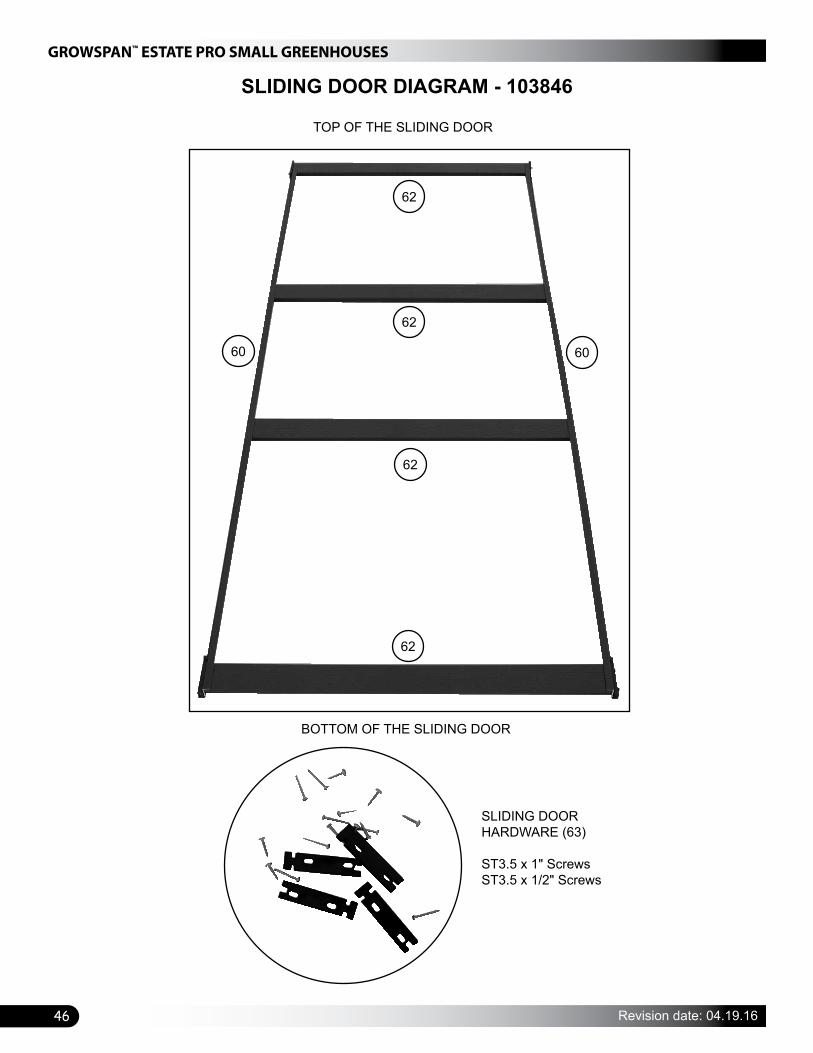
GROWSPAN™ ESTATE PRO SMALL GREENHOUSES
46 Revision date: 04.19.16
SLIDING DOOR DIAGRAM - 103846
TOP OF THE SLIDING DOOR
BOTTOM OF THE SLIDING DOOR
SLIDING DOOR HARDWARE (63)
ST3.5 x 1" ScrewsST3.5 x 1/2" Screws
62
62
62
62
6060
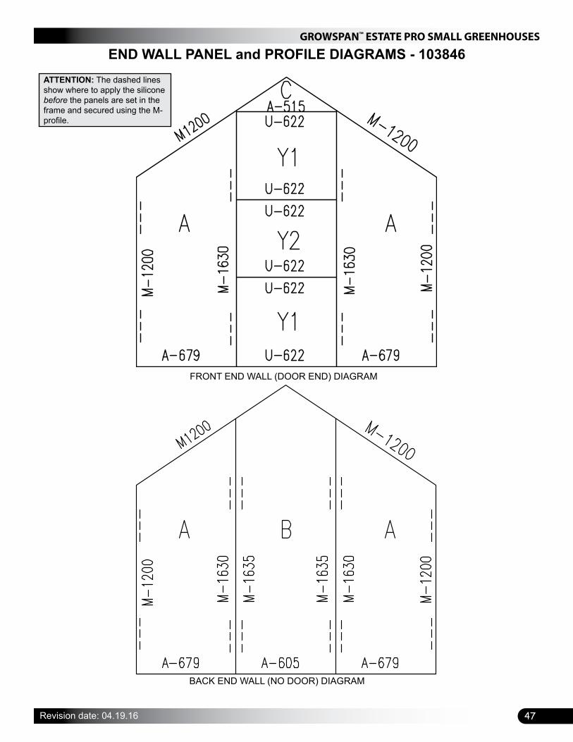
47
GROWSPAN™ ESTATE PRO SMALL GREENHOUSES
Revision date: 04.19.16
END WALL PANEL and PROFILE DIAGRAMS - 103846
FRONT END WALL (DOOR END) DIAGRAM
BACK END WALL (NO DOOR) DIAGRAM
ATTENTION: The dashed lines show where to apply the silicone before the panels are set in the frame and secured using the M-profile.

GROWSPAN™ ESTATE PRO SMALL GREENHOUSES
48 Revision date: 04.19.16
SIDEWALL AND ROOF PANEL and PROFILE DIAGRAM - 103846
32
ATTENTION: The dashed lines in the diagram below show where to apply the silicone before the panels are set in the frame and secured using the M-profile.
The details for the shaded area in the diagram to the right are shown in the diagram below.
SIDE VIEW OF THE ASSEMBLED GREENHOUSE
Ridge Beam
Gutter Rail51 5151
31 3131

49
GROWSPAN™ ESTATE PRO SMALL GREENHOUSES
Revision date: 04.19.16
Space below is reserved for customer notes.