Grove - 3-Axis Digital Accelerometer(±16g) · 2 1. Introduction This is a high resolution digital...
15
1 Grove - 3-Axis Digital Accelerometer(±16g) Version: 1.0 Release date: 9/20/2015 Wiki: http://www.seeedstudio.com/wiki/Grove_-_3-Axis_Digital_Accelerometer_ADXL345 Bazaar: http://www.seeedstudio.com/depot/Grove-3Axis-Digital-Accelerometer16g-p-1156.html
Transcript of Grove - 3-Axis Digital Accelerometer(±16g) · 2 1. Introduction This is a high resolution digital...

1
Grove - 3-Axis Digital
Accelerometer(±16g)
Version: 1.0
Release date: 9/20/2015
Wiki: http://www.seeedstudio.com/wiki/Grove_-_3-Axis_Digital_Accelerometer_ADXL345
Bazaar: http://www.seeedstudio.com/depot/Grove-3Axis-Digital-Accelerometer16g-p-1156.html

2
Document Revision History
Revision Date Author Description
1.0 Sep 21, 2015 Victor.He Create file

3
Contents
Document Revision History ··································································································· 2
1. Introduction ··················································································································· 2
2. Specifications ················································································································· 3
3. Demonstration ··············································································································· 4
3.1 With Arduino ····················································································································· 4
3.2 With Raspberry Pi ············································································································· 5
3.3 With Beaglebone Green ···································································································· 8
4. Resources ····················································································································· 12

1
Disclaimer
For physical injuries and possessions loss caused by those reasons which are not related to product quality,
such as operating without following manual guide, natural disasters or force majeure, we take no
responsibility for that.
Under the supervision of Seeed Technology Inc., this manual has been compiled and published which
covered the latest product description and specification. The content of this manual is subject to change
without notice.
Copyright
The design of this product (including software) and its accessories is under tutelage of laws. Any action to
violate relevant right of our product will be penalized through law. Please consciously observe relevant local
laws in the use of this product.

2
1. Introduction
This is a high resolution digital accelerometer providing you at max 3.9mg/LSB resolution and
large ±16g measurement range. It's based on an advanced 3-axis IC ADXL345. Have no worry to
implement it into your free-fall detection project, cause it's robust enough to survive up to 10,000g
shock. Meanwhile, it's agile enough to detect single and double taps. It's ideal for motion detection,
Gesture detection as well as robotics.

3
2. Specifications
Input Voltage: 3.3V, 5V
Test Range: ±16
High sensitivity
Large measurement range
Low power 0.1 μA in standby mode at VS = 2.5 V (typical)
10,000 g shock survival
RoHS/WEEE lead-free compliant
Suli-compatible Library
Note: More details about Suli-compatible Library, please refer to Suli

4
3. Demonstration
3.1 With Arduino
Every accelerometer has been individually tested before shipping to you. But in rare cases, you
might need to reset the zero-offset by yourself.
Here below we show you how to read the raw data and obtain data in the unit of g, AKA g-force,
from this accelerometer.
1. Plug it onto the I2C port of your Grove - Base Shield.
2. Download the Digital Accelerometer(±16g) Library .zip and unpack it into arduino-1.0\libraries
in your Arduino installation folder.
3. Open the demo code directly by the path:File -> Example
->DigitalAccelerometer_ADXL345->ADXL345_demo_code.
4. Upload the code and open the serial monitor. Please click here if you do not know how to
upload.
5. Open the serial monitor to check the result.

5
The outputs of this sensor consist of two parts: raw data and 3-axis acceleration info converted
into the unit of gravity, "g".
3.2 With Raspberry Pi
1. You should have got a raspberry pi and a grovepi or grovepi+.
2. You should have completed configuring the development environment, otherwise follow here.
3. Connection. Plug the sensor to grovepi socket i2c-x(1~3) by using a grove cable.
4. Navigate to the demos' directory:
cd yourpath/GrovePi/Software/Python/
To see the code

6
nano grovepi_tilt_switch.py # "Ctrl+x" to exit #
import smbus
from time import sleep
# select the correct i2c bus for this revision of Raspberry Pi
revision = ([l[12:-1] for l in open('/proc/cpuinfo','r').readlines() if
l[:8]=="Revision"]+['0000'])[0]
bus = smbus.SMBus(1 if int(revision, 16) >= 4 else 0)
# ADXL345 constants
EARTH_GRAVITY_MS2 = 9.80665
SCALE_MULTIPLIER = 0.004
DATA_FORMAT = 0x31
BW_RATE = 0x2C
POWER_CTL = 0x2D
BW_RATE_1600HZ = 0x0F
BW_RATE_800HZ = 0x0E
BW_RATE_400HZ = 0x0D
BW_RATE_200HZ = 0x0C
BW_RATE_100HZ = 0x0B
BW_RATE_50HZ = 0x0A
BW_RATE_25HZ = 0x09
RANGE_2G = 0x00
RANGE_4G = 0x01
RANGE_8G = 0x02
RANGE_16G = 0x03
MEASURE = 0x08
AXES_DATA = 0x32
class ADXL345:
address = None
def __init__(self, address = 0x53):
self.address = address
self.setBandwidthRate(BW_RATE_100HZ)
self.setRange(RANGE_2G)
self.enableMeasurement()

7
def enableMeasurement(self):
bus.write_byte_data(self.address, POWER_CTL, MEASURE)
def setBandwidthRate(self, rate_flag):
bus.write_byte_data(self.address, BW_RATE, rate_flag)
# set the measurement range for 10-bit readings
def setRange(self, range_flag):
value = bus.read_byte_data(self.address, DATA_FORMAT)
value &= ~0x0F;
value |= range_flag;
value |= 0x08;
bus.write_byte_data(self.address, DATA_FORMAT, value)
# returns the current reading from the sensor for each axis
#
# parameter gforce:
# False (default): result is returned in m/s^2
# True : result is returned in gs
def getAxes(self, gforce = False):
bytes = bus.read_i2c_block_data(self.address, AXES_DATA, 6)
x = bytes[0] | (bytes[1] << 8)
if(x & (1 << 16 - 1)):
x = x - (1<<16)
y = bytes[2] | (bytes[3] << 8)
if(y & (1 << 16 - 1)):
y = y - (1<<16)
z = bytes[4] | (bytes[5] << 8)
if(z & (1 << 16 - 1)):
z = z - (1<<16)
x = x * SCALE_MULTIPLIER
y = y * SCALE_MULTIPLIER
z = z * SCALE_MULTIPLIER
if gforce == False:
x = x * EARTH_GRAVITY_MS2
y = y * EARTH_GRAVITY_MS2

8
z = z * EARTH_GRAVITY_MS2
x = round(x, 4)
y = round(y, 4)
z = round(z, 4)
return {"x": x, "y": y, "z": z}
if __name__ == "__main__":
# if run directly we'll just create an instance of the class and
output
# the current readings
adxl345 = ADXL345()
axes = adxl345.getAxes(True)
print "ADXL345 on address 0x%x:" % (adxl345.address)
print " x = %.3fG" % ( axes['x'] )
print " y = %.3fG" % ( axes['y'] )
print " z = %.3fG" % ( axes['z'] )
5. Run the demo.
sudo python grove_tilt_switch.py
3.3 With Beaglebone Green
To begin editing programs that live on BBG, you can use the Cloud9 IDE.
As a simple exercise to become familiar with Cloud9 IDE, creating a simple application to blink one
of the 4 user programmable LEDs on the BeagleBone is a good start.
If this is your first time to use Cloud9 IDE, please follow this link.
Step1: Set the Grove - UART socket as a Grove - GPIO Socket, just follow this link.
Step2: Click the "+" in the top-right to create a new file.

9
Step3: Copy and paste the following code into the new tab
import smbus
import time
bus = smbus.SMBus(1)
# ADXL345 device address
ADXL345_DEVICE = 0x53
# ADXL345 constants
EARTH_GRAVITY_MS2 = 9.80665
SCALE_MULTIPLIER = 0.004
DATA_FORMAT = 0x31
BW_RATE = 0x2C
POWER_CTL = 0x2D
BW_RATE_1600HZ = 0x0F
BW_RATE_800HZ = 0x0E
BW_RATE_400HZ = 0x0D
BW_RATE_200HZ = 0x0C
BW_RATE_100HZ = 0x0B
BW_RATE_50HZ = 0x0A
BW_RATE_25HZ = 0x09
RANGE_2G = 0x00
RANGE_4G = 0x01
RANGE_8G = 0x02
RANGE_16G = 0x03

10
MEASURE = 0x08
AXES_DATA = 0x32
class ADXL345:
address = None
def __init__(self, address = ADXL345_DEVICE):
self.address = address
self.setBandwidthRate(BW_RATE_100HZ)
self.setRange(RANGE_2G)
self.enableMeasurement()
def enableMeasurement(self):
bus.write_byte_data(self.address, POWER_CTL, MEASURE)
def setBandwidthRate(self, rate_flag):
bus.write_byte_data(self.address, BW_RATE, rate_flag)
# set the measurement range for 10-bit readings
def setRange(self, range_flag):
value = bus.read_byte_data(self.address, DATA_FORMAT)
value &= ~0x0F;
value |= range_flag;
value |= 0x08;
bus.write_byte_data(self.address, DATA_FORMAT, value)
# returns the current reading from the sensor for each axis
#
# parameter gforce:
# False (default): result is returned in m/s^2
# True : result is returned in gs
def getAxes(self, gforce = False):
bytes = bus.read_i2c_block_data(self.address, AXES_DATA, 6)
x = bytes[0] | (bytes[1] << 8)
if(x & (1 << 16 - 1)):
x = x - (1<<16)
y = bytes[2] | (bytes[3] << 8)
if(y & (1 << 16 - 1)):
11
y = y - (1<<16)
z = bytes[4] | (bytes[5] << 8)
if(z & (1 << 16 - 1)):
z = z - (1<<16)
x = x * SCALE_MULTIPLIER
y = y * SCALE_MULTIPLIER
z = z * SCALE_MULTIPLIER
if gforce == False:
x = x * EARTH_GRAVITY_MS2
y = y * EARTH_GRAVITY_MS2
z = z * EARTH_GRAVITY_MS2
x = round(x, 4)
y = round(y, 4)
z = round(z, 4)
return {"x": x, "y": y, "z": z}
if __name__ == "__main__":
# if run directly we'll just create an instance of the class and
output
# the current readings
adxl345 = ADXL345()
while True:
axes = adxl345.getAxes(True)
print "ADXL345 on address 0x%x:" % (adxl345.address)
print " x = %.3fG" % ( axes['x'] )
print " y = %.3fG" % ( axes['y'] )
print " z = %.3fG" % ( axes['z'] )
time.sleep(2)
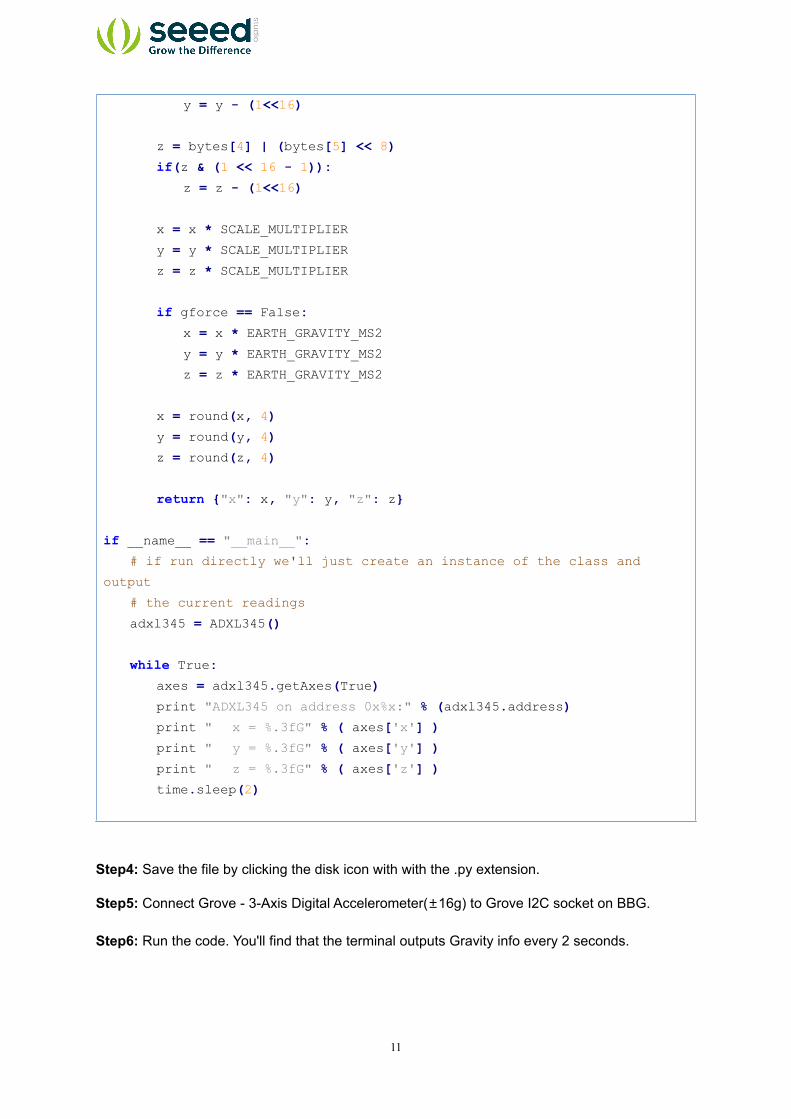
Step4: Save the file by clicking the disk icon with with the .py extension.
Step5: Connect Grove - 3-Axis Digital Accelerometer(±16g) to Grove I2C socket on BBG.
Step6: Run the code. You'll find that the terminal outputs Gravity info every 2 seconds.

12
4. Resources
Suli-compatible Library
github repository for 3-Axis Digital Accelerometer(±16g)
Digital Accelerometer(±16g) Library .zip
Grove - 3-Axis Digital Accelerometer(±16g) Eagle file.zip
ADXL345 datasheet.pdf