Group F Drink Mixer - MIXoTRON
68
Washington University in St. Louis Washington University in St. Louis Washington University Open Scholarship Washington University Open Scholarship Mechanical Engineering Design Project Class Mechanical Engineering & Materials Science Fall 12-9-2017 Group F Drink Mixer - MIXoTRON Group F Drink Mixer - MIXoTRON Rebecca Danielle Stone Washington University in St. Louis Christina Bell Washington University in St. Louis Devon Roell Washington University in St. Louis Follow this and additional works at: https://openscholarship.wustl.edu/mems411 Part of the Mechanical Engineering Commons Recommended Citation Recommended Citation Stone, Rebecca Danielle; Bell, Christina; and Roell, Devon, "Group F Drink Mixer - MIXoTRON" (2017). Mechanical Engineering Design Project Class. 78. https://openscholarship.wustl.edu/mems411/78 This Final Report is brought to you for free and open access by the Mechanical Engineering & Materials Science at Washington University Open Scholarship. It has been accepted for inclusion in Mechanical Engineering Design Project Class by an authorized administrator of Washington University Open Scholarship. For more information, please contact [email protected].
Transcript of Group F Drink Mixer - MIXoTRON
Washington University in St. Louis Washington University in St. Louis
Washington University Open Scholarship Washington University Open Scholarship
Mechanical Engineering Design Project Class Mechanical Engineering & Materials Science
Fall 12-9-2017
Group F Drink Mixer - MIXoTRON Group F Drink Mixer - MIXoTRON
Rebecca Danielle Stone Washington University in St. Louis
Christina Bell Washington University in St. Louis
Devon Roell Washington University in St. Louis
Follow this and additional works at: https://openscholarship.wustl.edu/mems411
Part of the Mechanical Engineering Commons
Recommended Citation Recommended Citation Stone, Rebecca Danielle; Bell, Christina; and Roell, Devon, "Group F Drink Mixer - MIXoTRON" (2017). Mechanical Engineering Design Project Class. 78. https://openscholarship.wustl.edu/mems411/78
This Final Report is brought to you for free and open access by the Mechanical Engineering & Materials Science at Washington University Open Scholarship. It has been accepted for inclusion in Mechanical Engineering Design Project Class by an authorized administrator of Washington University Open Scholarship. For more information, please contact [email protected].
Executive Summary
For our Mechanical Engineering Senior Design project, we designed and built the MIXoTRON, an
automatic bartending device. This device takes in a drink order from a user and automatically mixes the
drink by dispensing 1.5oz of each ingredient into the cup. This is done through movement in both the linear
and rotational z axis. The cup rests on a turntable that moves to orient the cup under a single bottle. The
bottles are then driven vertically downward by a lead screw to press against the cup and dispense the liquid.
Ideally, the MIXoTRON will be able to mix drinks in about the same time as, or faster than, a human
bartender would.
The current prototype has been fully assembled, but has not yet been programmed to take in an order or
move autonomously. The current programming utilizes four keypad buttons that activates four basic
functions: turning the turntable counter clockwise and clockwise, and moving the carriage holding the
bottles up and down the lead screw. There is also one button that stops all motion. If more time was
available, we would program the device to autonomously make a drink per user input.
MEMS 411: Senior Design Project
Drink Mixer
Christina Bell
Devon Roell
R. Dani Stone
MIXoTRON Introduction and Background Information
Page 1 of 67
TABLE OF CONTENTS
List of Figures 5
List of Tables 6
1 Introduction and Background Information 7
1.1 Initial Project Description 7
1.2 Existing Products 7
1.3 Relevant Patents 9
1.4 Codes & Standards 11
1.5 Project Scope 11
10.1 Project Planning 12
10.2 Realistic Constraints 12
10.2.1 Functional 12
10.2.2 Safety 13
10.2.3 Quality 13
10.2.4 Manufacturing 13
10.2.5 Timing 13
10.2.6 Economic 13
10.2.7 Ergonomic 13
10.2.8 Ecological 14
10.2.9 Aesthetic 14
10.2.10 Life Cycle 14
10.2.11 Legal 14
10.3 Revised Project Description 14
11 Customer Needs & Product Specifications 15
11.1 Customer Interviews 15
11.2 Interpreted Customer Needs 17
11.3 Target Specifications 18
12 Concept Generation 18
12.1 Functional Decomposition 18
12.2 Morphological Chart 20
MIXoTRON Introduction and Background Information
Page 2 of 67
12.3 Concept #1 – “Indrunkinator” 21
12.4 Concept #2 – “Drink-O-Matic” 22
12.5 Concept #3 – “Squeeze-o-Matic” 23
12.6 Concept #4 – “BloodyMary-go-Round” 24
12.7 Concept #5 – “Wheel of Booze” 25
12.8 Concept #6 – “MIXoTRON” 26
13 Concept Selection 27
13.1 Concept Scoring Matrix 27
13.2 Explanation of Winning Concept Scores 30
13.3 Explanation of Second-Place Concept Scores 30
13.4 Explanation of Third-Place Concept Scores 30
13.5 Summary of Evaluation Results 31
14 Embodiment & Fabrication plan 31
14.1 Isometric Drawing with Bill of Materials 31
14.2 Exploded View 34
14.3 Additional Views 35
15 Engineering Analysis 37
15.1 Engineering Analysis Results 37
15.1.1 Motivation 37
15.1.2 Summary Statement of the Analysis 38
15.1.3 Methodology 38
15.1.4 Results 43
15.1.5 Significance 43
15.2 Product Risk Assessment 44
15.2.1 Risk Identification 44
15.2.2 Risk Heat Map 45
15.2.3 Risk Prioritization 45
16 Design Documentation 46
16.1 Performance Goals 46
16.2 Working Prototype Demonstration 46
MIXoTRON Introduction and Background Information
Page 3 of 67
16.2.1 Performance Evaluation 46
16.2.2 Working Prototype – Video Link 48
16.2.3 Working Prototype – Additional Photos 48
17 Discussion 52
17.1 Design for Manufacturing – Part Redesign for Injection Molding 52
17.1.1 Explanation of Design Changes 52
17.2 Design for Usability – Effect of Impairments on Usability 52
17.2.1 Vision 52
17.2.2 Hearing 53
17.2.3 Physical 53
17.2.4 Language 53
7.2 Overall Experience 53
7.2.1 Does your final project result align with the initial project description? 53
7.2.2 Was the project more or less difficult than you had expected? 53
7.2.3 In what ways do you wish your final prototype would have performed better? 53
7.2.4 your group missing any critical information when you evaluated concepts? 53
7.2.5 Were there additional engineering analyses that could have helped guide your design? 54
7.2.6 How did you identify your most relevant codes and standards and how they influence
revision of the design? 54
7.2.7 What ethical considerations (from the Engineering Ethics and Design for Environment
seminar) are relevant to your device? How could these considerations be addressed? 54
7.2.8 On which part(s) of the design process should your group have spent more time? Which
parts required less time? 54
7.2.9 Was there a task on your Gantt chart that was much harder than expected? Were there any
that were much easier? 54
7.2.10 Was there a component of your prototype that was significantly easier or harder to
make/assemble than you expected? 54
7.2.11 If your budget were increased to 10x its original amount, would your approach have
changed? If so, in what specific ways? 55
7.2.12 If you were able to take the course again with the same project and group, what would you
have done differently the second time around? 55
7.2.13 Were your team member’s skills complementary? 55
MIXoTRON Introduction and Background Information
Page 4 of 67
7.2.14 Was any needed skill missing from the group? 55
7.2.15 Has the project enhanced your design skills? 55
7.2.16 Would you now feel more comfortable accepting a design project assignment at a job? 55
7.2.17 Are there projects you would attempt now that you would not have attempted before? 55
8 Appendix A - Parts List 56
9 Appendix B - CAD Models 57
10 Annotated Bibliography 66
MIXoTRON Introduction and Background Information
Page 5 of 67
LIST OF FIGURES
Figure 1: The Inebriator ................................................................................................................................ 7
Figure 2: The MakrShakr .............................................................................................................................. 8
Figure 3: Patent Number: US20110113967 A1 ............................................................................................ 9
Figure 4: Patent Number: US4590975 A .................................................................................................... 10
Figure 5: Gantt Chart .................................................................................................................................. 12
Figure 6: Function Tree .............................................................................................................................. 19
Figure 7: Morphological Chart ................................................................................................................... 20
Figure 8: Concept Drawing 1 – The Indrunkinator ..................................................................................... 21
Figure 9: Concept Drawing 2 – Drink-O-Matic .......................................................................................... 22
Figure 10: Concept Drawing 3 – Squeeze-o-Matic..................................................................................... 23
Figure 11: Concept Drawing 4 – BloodyMary-Go- Round ........................................................................ 24
Figure 12: Concept Drawing 5 – Wheel of Booze ...................................................................................... 25
Figure 13: Concept Drawing 6 – MIXoTRON ........................................................................................... 26
Figure 14: Isometric Drawing ..................................................................................................................... 32
Figure 15: Bill of Materials ......................................................................................................................... 32
Figure 16: Isometric View .......................................................................................................................... 33
Figure 17: Exploded View .......................................................................................................................... 34
Figure 18: Front View ................................................................................................................................. 35
Figure 19: Side View .................................................................................................................................. 36
Figure 20: Top View ................................................................................................................................... 37
Figure 21: Finding the torque of the lead screw motor ............................................................................... 39
Figure 22: Finding the load on the lead screw ............................................................................................ 39
Figure 23: Finding the torque required to drive the lead screw .................................................................. 40
Figure 24: Calculating the gear ratio required from the motor to the lead screw for different factors of
safety ........................................................................................................................................................... 40
Figure 25: Finding the required motor speed .............................................................................................. 41
Figure 26: Finding the critical speed of the lead screw .............................................................................. 42
Figure 27: Determining the actual speed of the motor ................................................................................ 42
Figure 28: Torque speed curve of the lead screw motor ............................................................................. 43
Figure 29: Risk identification template ....................................................................................................... 44
Figure 30: Risk Assessment Heat Map ....................................................................................................... 45
Figure 31: Total Current Draw and Battery Life Calculations [2] .............................................................. 47
Figure 32: Total Number of Recipes Calculation ....................................................................................... 47
Figure 33: Inner Circuitry of the MIXoTRON ........................................................................................... 48
Figure 34: The MIXoTRON in Operation .................................................................................................. 49
Figure 35: Disassembling the MIXoTRON ................................................................................................ 50
Figure 36: Volumetric Valve Dispensing Liquid ........................................................................................ 51
Figure 37: Before and after comparison of one of the lead screw gears chosen for draft analysis ............. 52
Figure 38: Parts List .................................................................................................................................... 56
MIXoTRON Introduction and Background Information
Page 6 of 67
Figure 39: CAD Drawing of Lazy Susan .................................................................................................... 57
Figure 40: CAD Drawing of Wooden Base ................................................................................................ 58
Figure 41: Lead Screw Gear, Modified from McMaster Part 6832K6600 ................................................. 59
Figure 42: McMaster Gear Modified for Lead Screw ................................................................................ 60
Figure 43: Motor Gear, Modified from McMaster Part 6832K6590 .......................................................... 61
Figure 44: McMaster Gear Modified for Motor Gear ................................................................................. 62
Figure 45: CAD Drawing of Threaded Rod, Received from McMaster ..................................................... 63
Figure 46: CAD Drawing of Turntable, Received from McMaster ............................................................ 64
Figure 47: CAD Drawing of Thrust Bearing, Received from McMaster ................................................... 65
LIST OF TABLES
Table 1: Customer Interview 1 - Breanna Gillette - Bartender at Glory Days Grill – 9/13/2017 ............... 15
Table 2: Customer Interview 1 - Cathryn Boggs - Bartender at Captain Billy's Crab Shack – 9/17/2017 . 16
Table 3: Interpreted Customer Needs ......................................................................................................... 17
Table 4: Target Specifications .................................................................................................................... 18
Table 5: Concept Scoring Matrix (1 of 3) ................................................................................................... 27
Table 6: Concept Scoring Matrix (2 of 3) ................................................................................................... 28
Table 7: Concept Scoring Matrix (3 of 3) ................................................................................................... 29
MIXoTRON Introduction and Background Information
Page 7 of 67
1 INTRODUCTION AND BACKGROUND INFORMATION
1.1 INITIAL PROJECT DESCRIPTION
Bars are a great setting for friends to meet and drink however there aren’t many special features that set
one bar apart from the rest. What you won’t find in any bar today is robotic bartender able to make any
drink to order.
In addition, there are many ways to make certain drinks, allowing for much variation. Automating the
cocktail making process eliminates the variation in alcohol levels and in ingredients used. In addition, it
guarantees that your drink will not have anything in it that the customer does not explicitly see. Giving
the customer options of existing drinks and customizable features will ensure a smooth and enjoyable
drinking experience for everyone.
1.2 EXISTING PRODUCTS
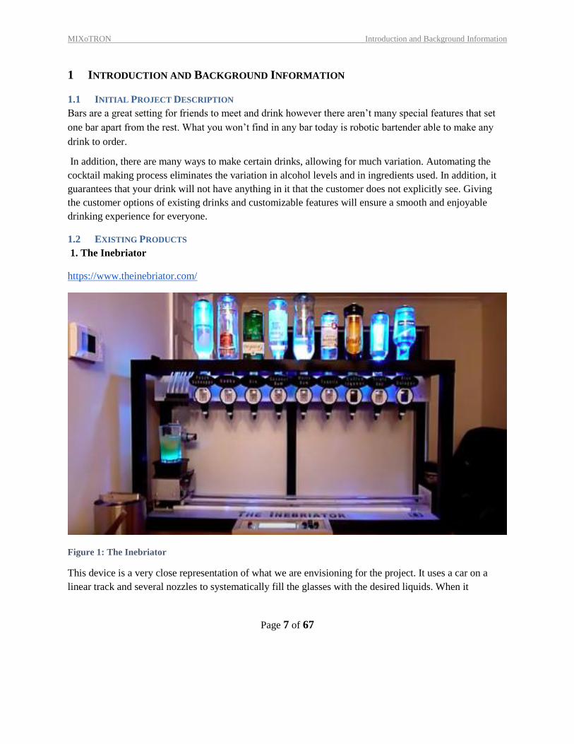
1. The Inebriator
https://www.theinebriator.com/
Figure 1: The Inebriator
This device is a very close representation of what we are envisioning for the project. It uses a car on a
linear track and several nozzles to systematically fill the glasses with the desired liquids. When it
MIXoTRON Introduction and Background Information
Page 8 of 67
completes its run and is finished filling the glass, the stand on which the glass sits on flashes a bluish
color to indicates it is finished.
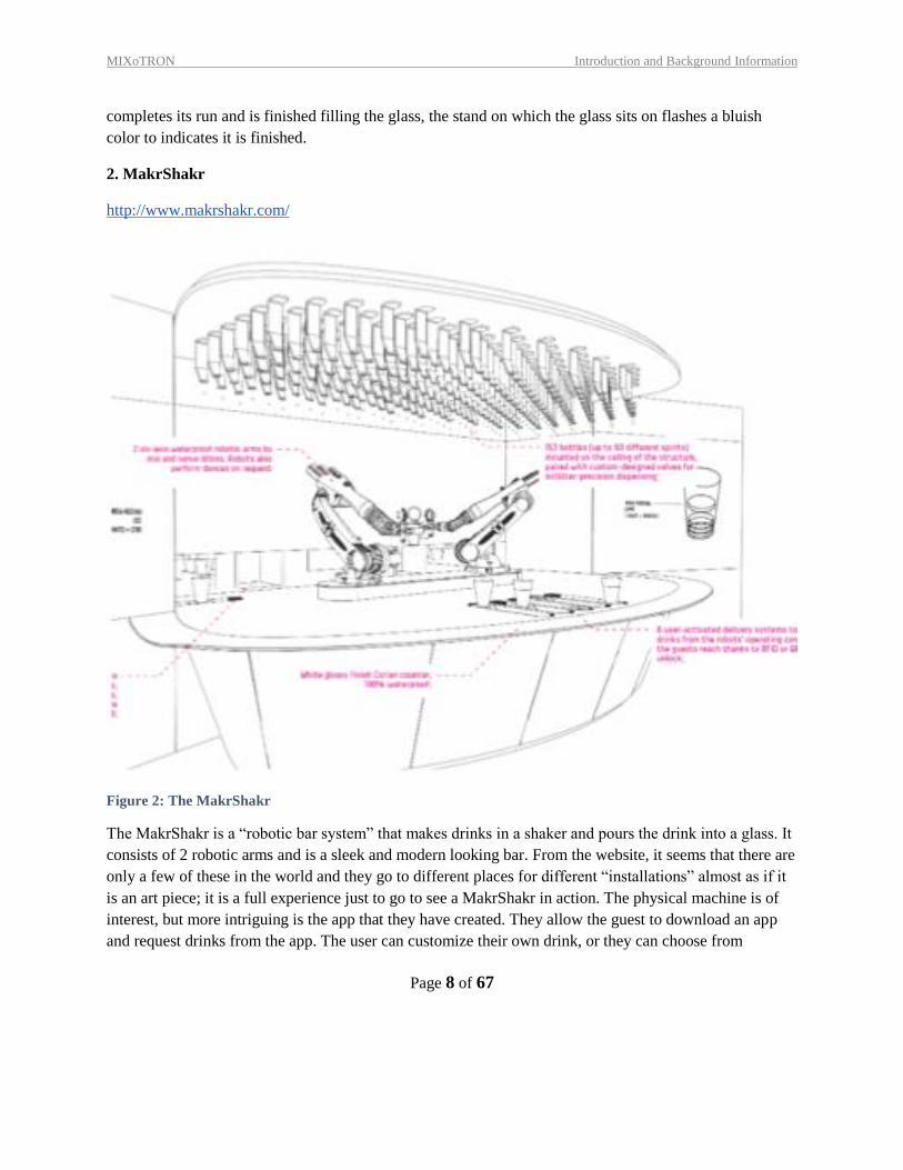
2. MakrShakr
http://www.makrshakr.com/
Figure 2: The MakrShakr
The MakrShakr is a “robotic bar system” that makes drinks in a shaker and pours the drink into a glass. It
consists of 2 robotic arms and is a sleek and modern looking bar. From the website, it seems that there are
only a few of these in the world and they go to different places for different “installations” almost as if it
is an art piece; it is a full experience just to go to see a MakrShakr in action. The physical machine is of
interest, but more intriguing is the app that they have created. They allow the guest to download an app
and request drinks from the app. The user can customize their own drink, or they can choose from
MIXoTRON Introduction and Background Information
Page 9 of 67
existing drinks. Users can also communicate with other patrons and select the drinks others make. In
addition, users can rate and comment the drinks of others, giving suggestions on drink recipes.
1.3 RELEVANT PATENTS
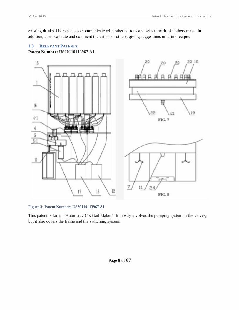
Patent Number: US20110113967 A1
Figure 3: Patent Number: US20110113967 A1
This patent is for an “Automatic Cocktail Maker”. It mostly involves the pumping system in the valves,
but it also covers the frame and the switching system.
MIXoTRON Introduction and Background Information
Page 10 of 67
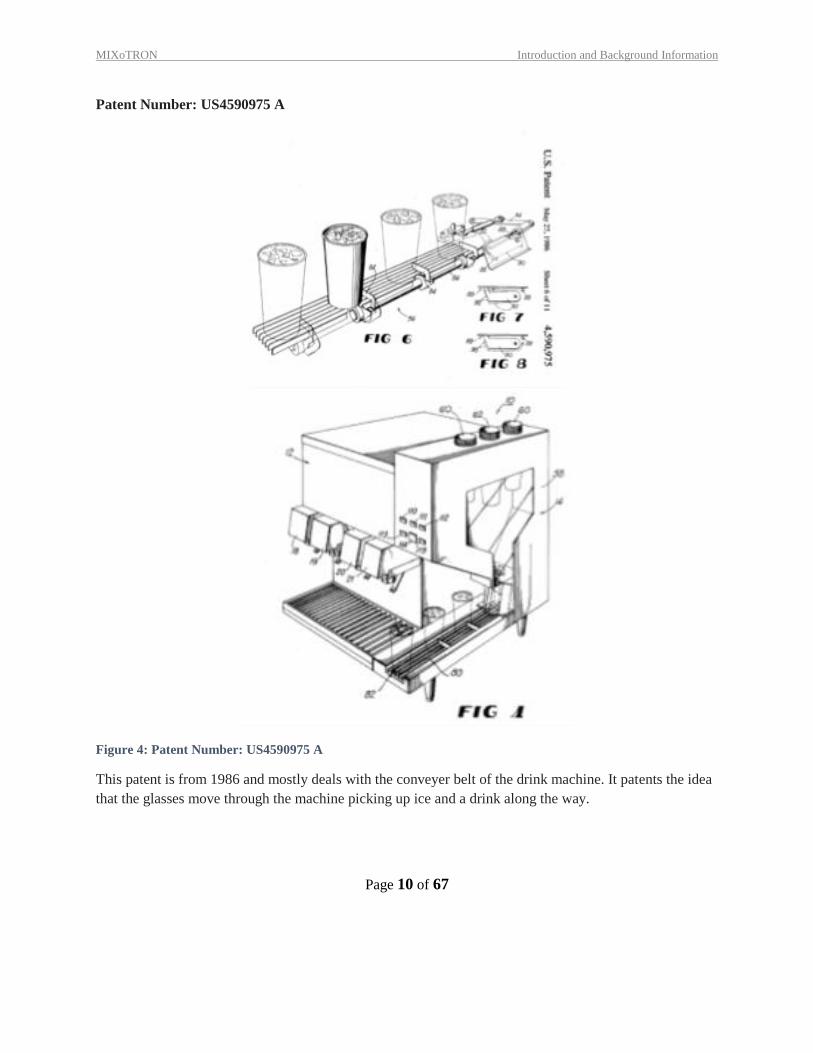
Patent Number: US4590975 A
Figure 4: Patent Number: US4590975 A
This patent is from 1986 and mostly deals with the conveyer belt of the drink machine. It patents the idea
that the glasses move through the machine picking up ice and a drink along the way.
MIXoTRON Introduction and Background Information
Page 11 of 67
1.4 CODES & STANDARDS
Code: NSF/ANSI 18 - 2016, Manual Food and Beverage Dispensing Equipment.
1.5 PROJECT SCOPE
1 Our project is the Automatic Drink Maker. The purpose of this machine is to dispense and mix
made-to-order alcoholic beverages.
2 We will be making this product for sports bars, tech bars and other sorts of novelty bars where the
machine will complement the aesthetic.
3 This machine will assist the bartender in increasing their productivity. It will also regulate the
amount of alcohol in each drink, ensuring that the bar owners are not over- or under-pouring their
drinks. This will both reduce wasted alcohol while maintaining the drink quality. Customers may
feel more comfortable with an automated drink maker to avoid human error or malevolent intent. It
could also bring in more patrons who are interested in a novel drinking experience.
4 This machine will, given an order (input), dispense a well-mixed alcoholic beverage in under 30
seconds.
5 The project will get people their drinks in a timely and entertaining manner. It will mix the drink.
The machine will also communicate drink status while also trivially conversing with the patron.
6 Our drink mixer will only make individually sized drinks. It will not require identification in order to
operate the machine.
7 The project must
a. Accurately follow and execute a recipe
b. Thoroughly mix a drink
c. Effectively communicate drink status
d. Accurately pour liquids into one glass
e. Accurately log amount of alcohol in reserves
8 Assumptions
a. Our customer wouldn’t want to stir their own drink
b. Customers will enjoy a uniform recipe for drinks
c. Shaking is necessary at all
9 Constraints
a. Time- 1 semester
b. Cost- unknown
c. Scheduling- between class schedule and work
10 Deliverables
a. User interface with drink options
b. Mixing component
c. A piping system to deliver drinks to reservoir
MIXoTRON Introduction and Background Information
Page 12 of 67
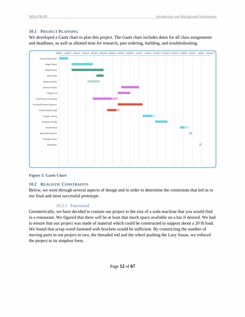
10.1 PROJECT PLANNING
We developed a Gantt chart to plan this project. The Gantt chart includes dates for all class assignments
and deadlines, as well as allotted time for research, part ordering, building, and troubleshooting.
Figure 5: Gantt Chart
10.2 REALISTIC CONSTRAINTS
Below, we went through several aspects of design and in order to determine the constraints that led us to
our final and most successful prototype.
10.2.1 Functional
Geometrically, we have decided to contain our project to the size of a soda machine that you would find
in a restaurant. We figured that there will be at least that much space available on a bar if desired. We had
to ensure that our project was made of material which could be constructed to support about a 20 lb load.
We found that scrap wood fastened with brackets would be sufficient. By constricting the number of
moving parts in out project to two, the threaded rod and the wheel pushing the Lazy Susan, we reduced
the project to its simplest form.
MIXoTRON Introduction and Background Information
Page 13 of 67
10.2.2 Safety
In terms of safety, we are constrained to the beverage dispensing safety standard depicted in Section 1.4
above. We have adhered to this standard by making the parts of the system that are in contact with the
beverages are easily removable and easily cleanable. We will ensure that all personnel operating the
machine are well trained in disassembling and cleaning the machine. In addition, we have considered
implementing an ID scanner to ensure that patrons are of age to be consuming alcoholic beverages.
10.2.3 Quality
As mentioned above, we are currently adhering to the safety and quality regulations. A main point of our
project is to ensure quality and consistency of the cocktails produced by the machine. The volumetric
valves confirm that each time the liquid is dispensed, it dispenses 1.5 oz.
10.2.4 Manufacturing
For manufacturing, we were limited to building materials available within university storage. To
minimize upfront costs, we used scavenged wood for the frame and base as well as plexiglass for the
rotation surface. Several design choices were made based on what materials were already on hand. We
were also limited to the equipment in the machine shops on campus. While some of these machines are
quite precise (such as the milling machine), we also had to make use of less-precise machines, such as the
bandsaw.
10.2.5 Timing
Our time spent on this project was, of course, constrained to one 14-week semester. We met for recitation
2 hours every week to work on our project with an additional 2-10 hours per week outside of class time.
10.2.6 Economic
As mentioned in manufacturing, we decided to use wood as the material for the majority of our
components. Campus had a ready supply of plywood and cutting equipment which allowed the entirety of
our budget to go to specialty components and electronics. We were also provided a budget of $161.28.
This money was budgeted to cover the cost of the volumetric valves and bottle holder, various electronic
equipment, and other materials that we could not salvage from university storage.
10.2.7 Ergonomic
Ergonomic constraints have to do with the interface between the user and the device. In our case, we have
two different kinds of users: the customer and the bartender. First, the customer uses the device to make a
custom drink of their choosing. This means that the interface we choose must be easy to read and easy to
use to select the drink. The bartender, then must make sure that the machine is clean and in working
condition. This means that the device must be easy to clean (i.e. at a decent height so as not to cause back
pain when cleaning or maintaining it) and have very low basic maintenance requirements.

MIXoTRON Introduction and Background Information
Page 14 of 67
10.2.8 Ecological
There are not many ecological constraints for our project. The only power source used is a battery pack
and in the final design, this will move to just be plugged into the wall. We could remind all bar owners to
make sure to recycle the bottles used.
10.2.9 Aesthetic
The aesthetic appeal of our project was another main focus for us. We think that displaying the bottles
upside down in the rack makes the machine look cool and intriguing. The circular motion of the Lazy
Susan is also a fun aspect to the machine. In future iterations, our design would take a sleeker shape.
10.2.10 Life Cycle
The main realistic life cycle constraints that applied to our project was that the materials we chose to build
this project must be able to be salvaged for future projects. This meant designing a project that was fairly
simple to completely assemble and disassemble without destroying any parts. Most materials that were
used for this project were those that were salvaged from university storage. As long as we take good care
of the materials we gather, we should be able to return everything to storage.
10.2.11 Legal
As long as we are adhering to the beverage dispensing standard and our patrons are drinking responsibly,
we should have no legal issues. If an ID scanner is implemented, we could consider limiting the number
of drinks per patron to make sure we will not overserve patrons.
10.3 REVISED PROJECT DESCRIPTION
Bars are a great setting for friends to meet and drink however there aren’t many special features that set
one bar apart from the rest. What you won’t find in any bar today is robotic bartender able to make any
drink to order.
In addition, there are many ways to make certain drinks, allowing for much variation. Automating the
cocktail making process eliminates the variation in alcohol levels and in ingredients used. In addition, it
guarantees that a customer’s drink will not have anything in it that the customer does not explicitly see.
Giving the customer options of existing drinks and customizable features will ensure a smooth and
enjoyable drinking experience for everyone.
MIXoTRON Introduction and Background Information
Page 15 of 67
11 CUSTOMER NEEDS & PRODUCT SPECIFICATIONS
11.1 CUSTOMER INTERVIEWS
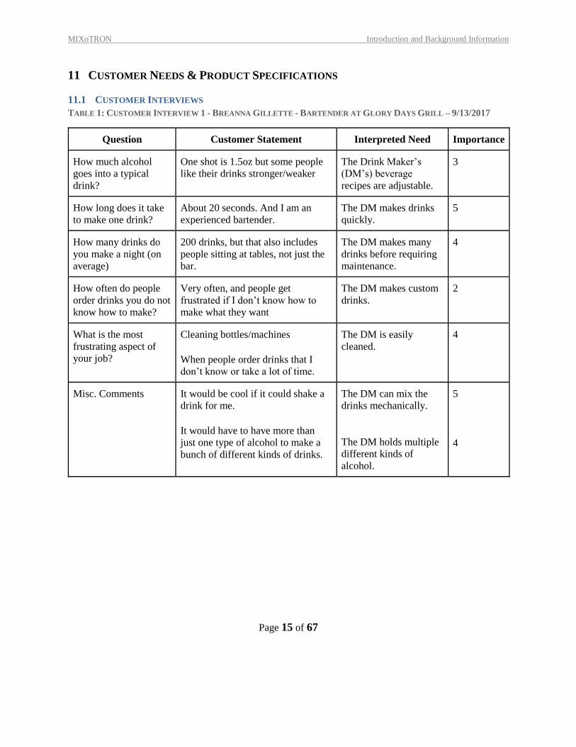
TABLE 1: CUSTOMER INTERVIEW 1 - BREANNA GILLETTE - BARTENDER AT GLORY DAYS GRILL – 9/13/2017
Question Customer Statement Interpreted Need Importance
How much alcohol
goes into a typical
drink?
One shot is 1.5oz but some people
like their drinks stronger/weaker The Drink Maker’s
(DM’s) beverage
recipes are adjustable.
3
How long does it take
to make one drink? About 20 seconds. And I am an
experienced bartender. The DM makes drinks
quickly. 5
How many drinks do
you make a night (on
average)
200 drinks, but that also includes
people sitting at tables, not just the
bar.
The DM makes many
drinks before requiring
maintenance.
4
How often do people
order drinks you do not
know how to make?
Very often, and people get
frustrated if I don’t know how to
make what they want
The DM makes custom
drinks. 2
What is the most
frustrating aspect of
your job?
Cleaning bottles/machines
When people order drinks that I
don’t know or take a lot of time.
The DM is easily
cleaned. 4
Misc. Comments It would be cool if it could shake a
drink for me.
It would have to have more than
just one type of alcohol to make a
bunch of different kinds of drinks.
The DM can mix the
drinks mechanically.
The DM holds multiple
different kinds of
alcohol.
5
4
MIXoTRON Introduction and Background Information
Page 16 of 67
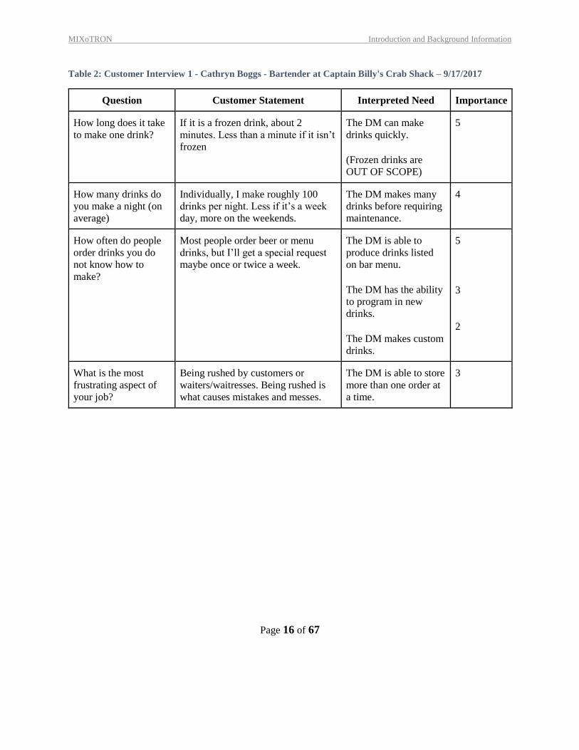
Table 2: Customer Interview 1 - Cathryn Boggs - Bartender at Captain Billy's Crab Shack – 9/17/2017
Question Customer Statement Interpreted Need Importance
How long does it take
to make one drink? If it is a frozen drink, about 2
minutes. Less than a minute if it isn’t
frozen
The DM can make
drinks quickly. (Frozen drinks are
OUT OF SCOPE)
5
How many drinks do
you make a night (on
average)
Individually, I make roughly 100
drinks per night. Less if it’s a week
day, more on the weekends.
The DM makes many
drinks before requiring
maintenance.
4
How often do people
order drinks you do
not know how to
make?
Most people order beer or menu
drinks, but I’ll get a special request
maybe once or twice a week.
The DM is able to
produce drinks listed
on bar menu.
The DM has the ability
to program in new
drinks.
The DM makes custom
drinks.
5
3
2
What is the most
frustrating aspect of
your job?
Being rushed by customers or
waiters/waitresses. Being rushed is
what causes mistakes and messes.
The DM is able to store
more than one order at
a time.
3
MIXoTRON Introduction and Background Information
Page 17 of 67
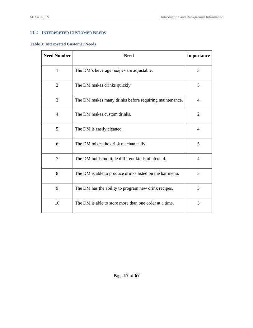
11.2 INTERPRETED CUSTOMER NEEDS
Table 3: Interpreted Customer Needs
Need Number Need Importance
1 The DM’s beverage recipes are adjustable. 3
2 The DM makes drinks quickly. 5
3 The DM makes many drinks before requiring maintenance. 4
4 The DM makes custom drinks. 2
5 The DM is easily cleaned. 4
6 The DM mixes the drink mechanically. 5
7 The DM holds multiple different kinds of alcohol. 4
8 The DM is able to produce drinks listed on the bar menu. 5
9 The DM has the ability to program new drink recipes. 3
10 The DM is able to store more than one order at a time. 3
MIXoTRON Introduction and Background Information
Page 18 of 67
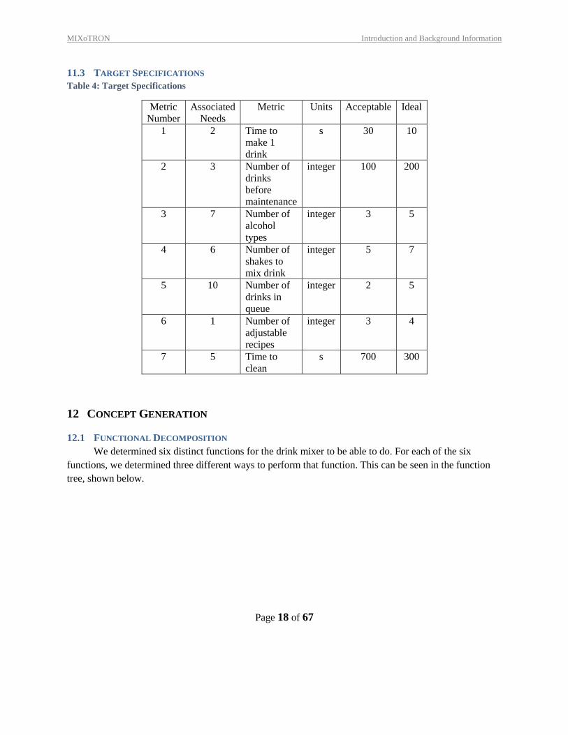
11.3 TARGET SPECIFICATIONS
Table 4: Target Specifications
Metric
Number
Associated
Needs
Metric Units Acceptable Ideal
1 2 Time to
make 1
drink
s 30 10
2 3 Number of
drinks
before
maintenance
integer 100 200
3 7 Number of
alcohol
types
integer 3 5
4 6 Number of
shakes to
mix drink
integer 5 7
5 10 Number of
drinks in
queue
integer 2 5
6 1 Number of
adjustable
recipes
integer 3 4
7 5 Time to
clean
s 700 300
12 CONCEPT GENERATION
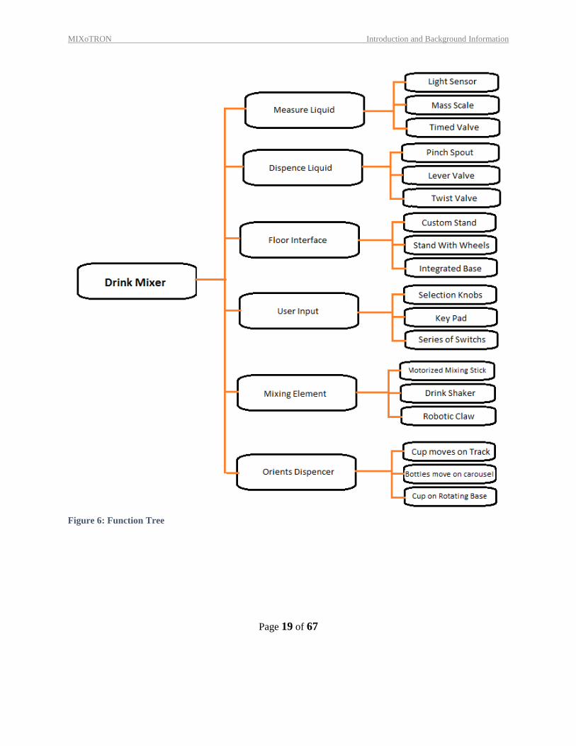
12.1 FUNCTIONAL DECOMPOSITION
We determined six distinct functions for the drink mixer to be able to do. For each of the six
functions, we determined three different ways to perform that function. This can be seen in the function
tree, shown below.
MIXoTRON Introduction and Background Information
Page 19 of 67
Figure 6: Function Tree
MIXoTRON Introduction and Background Information
Page 20 of 67
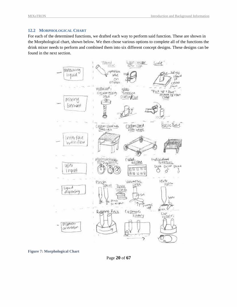
12.2 MORPHOLOGICAL CHART
For each of the determined functions, we drafted each way to perform said function. These are shown in
the Morphological chart, shown below. We then chose various options to complete all of the functions the
drink mixer needs to perform and combined them into six different concept designs. These designs can be
found in the next section.
Figure 7: Morphological Chart
MIXoTRON Introduction and Background Information
Page 21 of 67
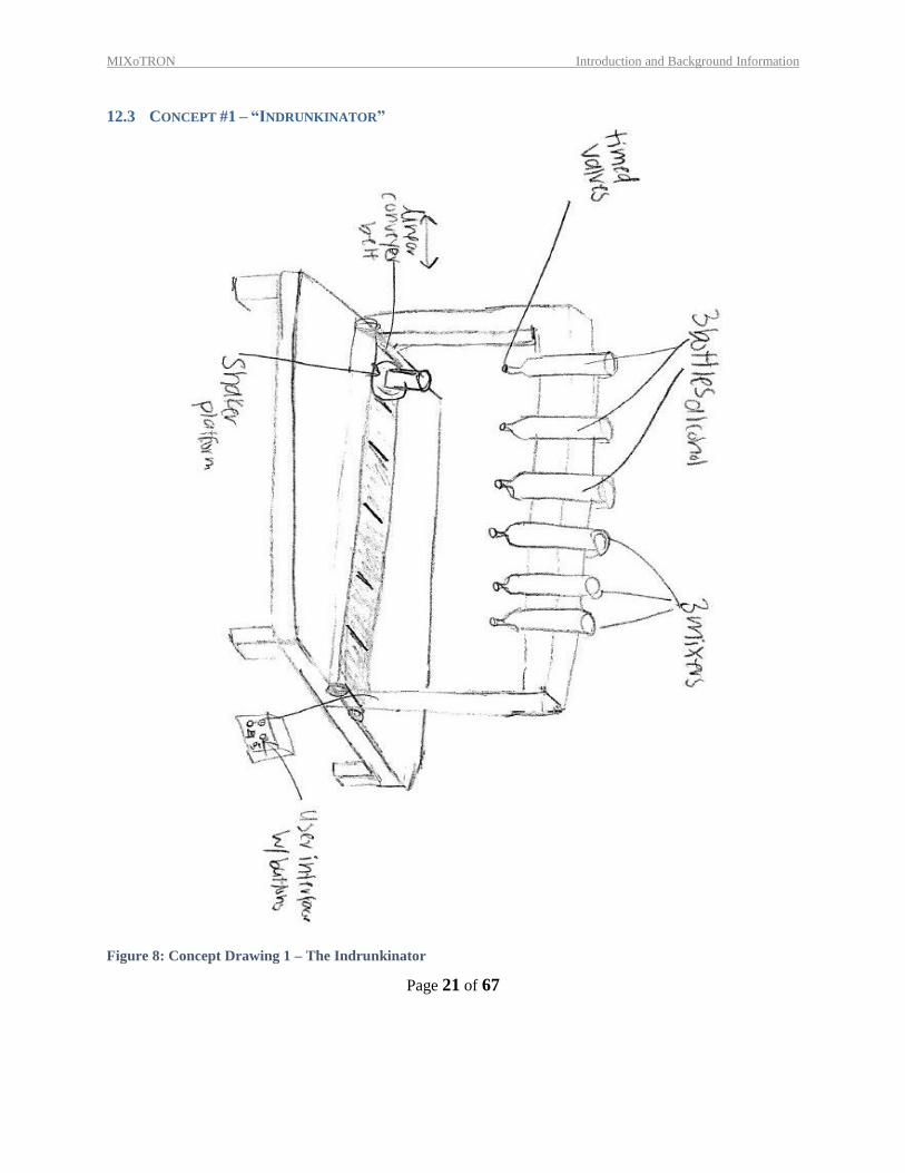
12.3 CONCEPT #1 – “INDRUNKINATOR”
Figure 8: Concept Drawing 1 – The Indrunkinator
MIXoTRON Introduction and Background Information
Page 22 of 67
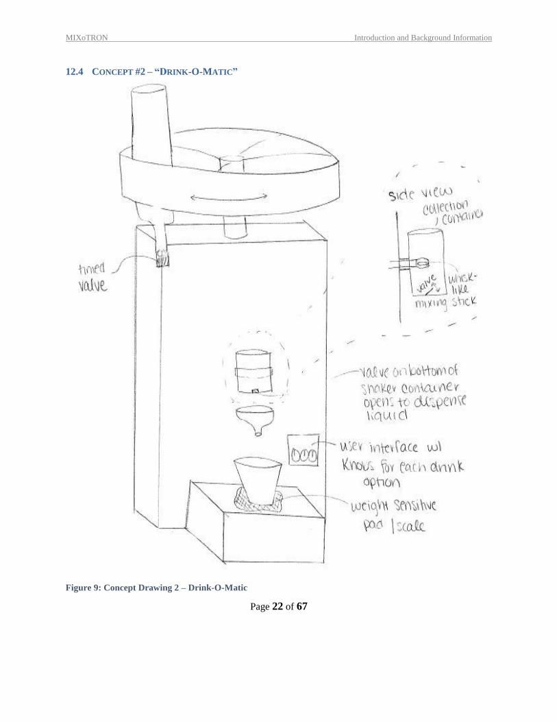
12.4 CONCEPT #2 – “DRINK-O-MATIC”
Figure 9: Concept Drawing 2 – Drink-O-Matic
MIXoTRON Introduction and Background Information
Page 23 of 67
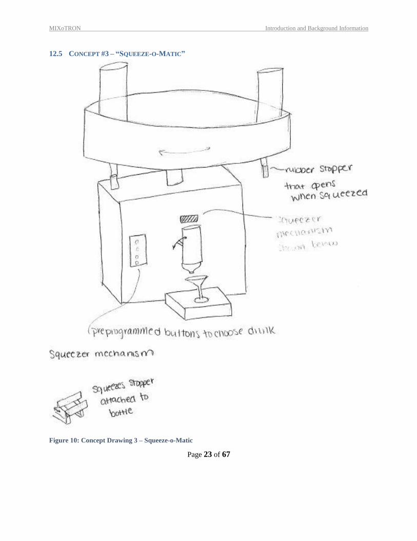
12.5 CONCEPT #3 – “SQUEEZE-O-MATIC”
Figure 10: Concept Drawing 3 – Squeeze-o-Matic
MIXoTRON Introduction and Background Information
Page 24 of 67
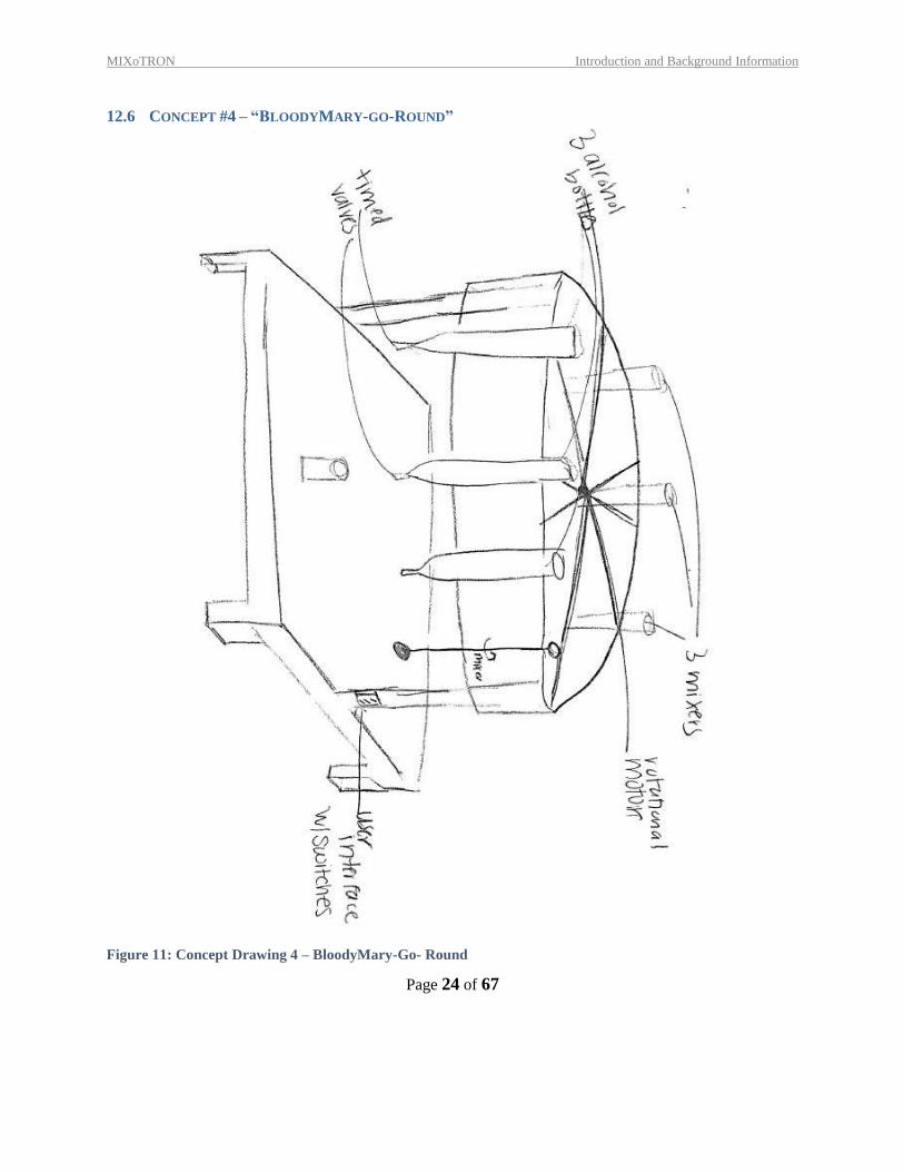
12.6 CONCEPT #4 – “BLOODYMARY-GO-ROUND”
Figure 11: Concept Drawing 4 – BloodyMary-Go- Round
MIXoTRON Introduction and Background Information
Page 25 of 67
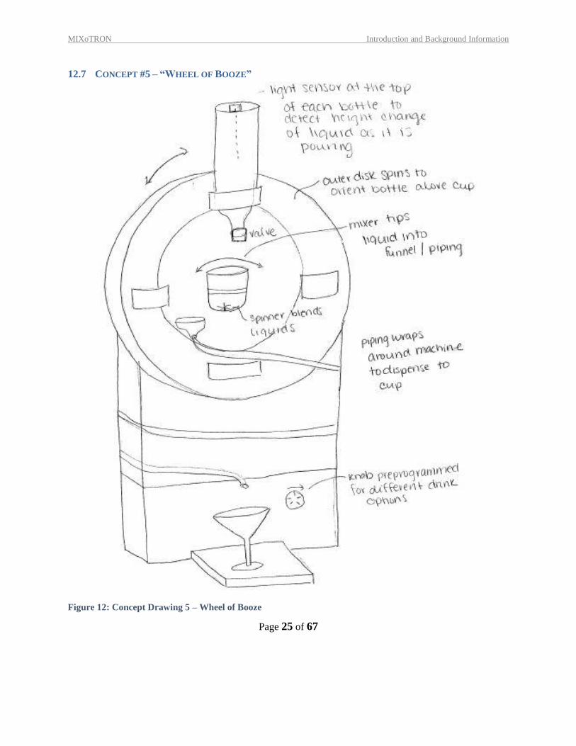
12.7 CONCEPT #5 – “WHEEL OF BOOZE”
Figure 12: Concept Drawing 5 – Wheel of Booze
MIXoTRON Introduction and Background Information
Page 26 of 67
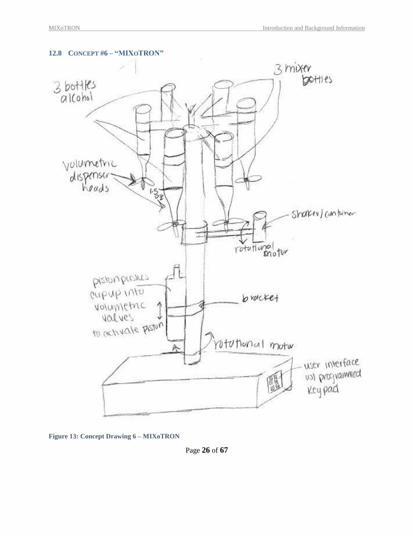
12.8 CONCEPT #6 – “MIXOTRON”
Figure 13: Concept Drawing 6 – MIXoTRON
MIXoTRON Introduction and Background Information
Page 27 of 67
13 CONCEPT SELECTION
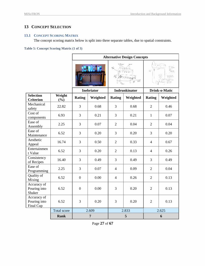
13.1 CONCEPT SCORING MATRIX
The concept scoring matrix below is split into three separate tables, due to spatial constraints.
Table 5: Concept Scoring Matrix (1 of 3)
Alternative Design Concepts
Inebriator Indrunkinator Drink-o-Matic
Selection
Criterion
Weight
(%) Rating Weighted Rating Weighted Rating Weighted
Mechanical
safety 22.82 3 0.68 3 0.68 2 0.46
Cost of
components 6.93 3 0.21 3 0.21 1 0.07
Ease of
Assembly 2.25 3 0.07 2 0.04 2 0.04
Ease of
Maintenance 6.52 3 0.20 3 0.20 3 0.20
Aesthetic
Appeal 16.74 3 0.50 2 0.33 4 0.67
Entertainmen
t Value 6.52 3 0.20 2 0.13 4 0.26
Consistency
of Recipes 16.40 3 0.49 3 0.49 3 0.49
Ease of
Programming 2.25 3 0.07 4 0.09 2 0.04
Quality of
Mixing 6.52 0 0.00 4 0.26 2 0.13
Accuracy of
Pouring into
Shaker
6.52 0 0.00 3 0.20 2 0.13
Accuracy of
Pouring into
Final Cup
6.52 3 0.20 3 0.20 2 0.13
Total score 2.609 2.833 2.625
Rank 7 5 6
MIXoTRON Introduction and Background Information
Page 28 of 67
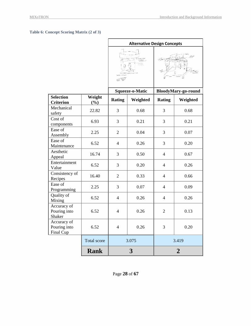
Table 6: Concept Scoring Matrix (2 of 3)
Alternative Design Concepts
Squeeze-o-Matic BloodyMary-go-round
Selection
Criterion
Weight
(%) Rating Weighted Rating Weighted
Mechanical
safety 22.82 3 0.68 3 0.68
Cost of
components 6.93 3 0.21 3 0.21
Ease of
Assembly 2.25 2 0.04 3 0.07
Ease of
Maintenance 6.52 4 0.26 3 0.20
Aesthetic
Appeal 16.74 3 0.50 4 0.67
Entertainment
Value 6.52 3 0.20 4 0.26
Consistency of
Recipes 16.40 2 0.33 4 0.66
Ease of
Programming 2.25 3 0.07 4 0.09
Quality of
Mixing 6.52 4 0.26 4 0.26
Accuracy of
Pouring into
Shaker
6.52 4 0.26 2 0.13
Accuracy of
Pouring into
Final Cup
6.52 4 0.26 3 0.20
Total score 3.075 3.419
Rank 3 2
MIXoTRON Introduction and Background Information
Page 29 of 67
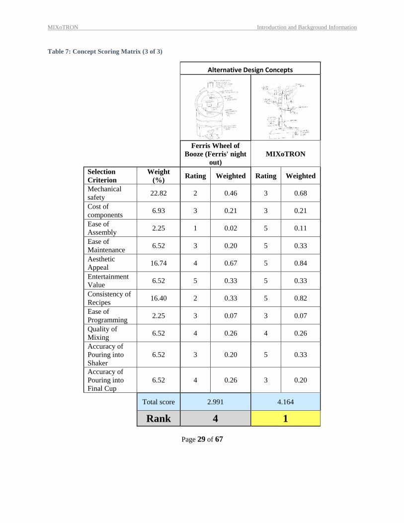
Table 7: Concept Scoring Matrix (3 of 3)
Alternative Design Concepts
Ferris Wheel of
Booze (Ferris' night
out)
MIXoTRON
Selection
Criterion
Weight
(%) Rating Weighted Rating Weighted
Mechanical
safety 22.82 2 0.46 3 0.68
Cost of
components 6.93 3 0.21 3 0.21
Ease of
Assembly 2.25 1 0.02 5 0.11
Ease of
Maintenance 6.52 3 0.20 5 0.33
Aesthetic
Appeal 16.74 4 0.67 5 0.84
Entertainment
Value 6.52 5 0.33 5 0.33
Consistency of
Recipes 16.40 2 0.33 5 0.82
Ease of
Programming 2.25 3 0.07 3 0.07
Quality of
Mixing 6.52 4 0.26 4 0.26
Accuracy of
Pouring into
Shaker
6.52 3 0.20 5 0.33
Accuracy of
Pouring into
Final Cup
6.52 4 0.26 3 0.20
Total score 2.991 4.164
Rank 4 1
MIXoTRON Introduction and Background Information
Page 30 of 67
According to the Scoring Matrix, the MIXoTRON is the winning design with a total score of 4.164 out of
5. The BloodyMary-go-Round was the second-place concept with a score of 3.419 out of 5. The third-
place concept with a score of 3.075 out of 5. All of the proposed concepts scored better than the base-line
concept, the Inebriator, mostly because of the fact that the Inebriator does not have any kind of mixing
mechanism.
13.2 EXPLANATION OF WINNING CONCEPT SCORES
The MIXoTRON scored significantly higher in 6 of the 11 selection criterion than the other 5 designs:
ease of assembly, ease of maintenance, aesthetic appeal, entertainment value, recipe consistency, and
mixing quality. The bottles and shaker mechanism are both connected to the center shaft, making the
design easy to assemble, as well as simple and pleasing to look at. The three different movements of this
machine make it very entertaining to watch. The top of the assembly, where all the bottles are stored, will
rotate around the shaft to orient a specific bottle above the shaker cup, according to the recipe chosen. The
piston will then raise to lift the cup into the push valve on the bottle, dispensing exactly 1.5 oz. of liquid
into the cup. This will repeat until the recipe for the chosen drink is compete. Then, the shaker arm will
shake the cup, rotating it about the shaker arm roughly -15° to 15°. All of these moving parts will make
the MIXoTRON a very interesting piece of machinery. The volumetric dispenser heads provide the most
consistency in the amount of liquid dispensed from the bottles, as opposed to a timer mechanism. The
volumetric dispenser releases exactly 1.5 oz. of liquid every time the dispenser is pressed. The shaker will
rotate roughly -15° to 15°, making the mixing thorough and consistent. The other 5 selection criterion
were relatively similar to the other designs.
13.3 EXPLANATION OF SECOND-PLACE CONCEPT SCORES
The Bloody Mary-Go-Round scored very high in the aesthetic categories. The rotation of the bottles is a
very dynamic and exciting motion, that many will find entertaining. In addition, since it has a component
that enters the cup and mixes the liquid inside, it scored above average in the Mixing Quality criteria. A
mechanical stirrer would mix the drink fairly well, however there are a few problems that come with it:
the stirrer would need to be cleaned between each drink, and the motion is less dynamic and entertaining.
It is because of these problems that this concept was not the winning design. It also scored above average
in the “ease of programming,” because it the main part of the mechanism requires a rotational motor,
which can be easily programmed by defining one bottle as a “zero” radian value, and programming the
rotation relative to that bottle. Most of the other selection criterion were relatively the same as the other
options, however there one that was given a low score. The accuracy of pouring the liquids into the shaker
is lower than average is due to difficulties in measuring liquid flow using timed valves.
13.4 EXPLANATION OF THIRD-PLACE CONCEPT SCORES
The Squeeze-o-matic ranks high in a few of the selection categories. The mixing quality, the accuracy of
pouring the liquids into the shaker and the accuracy of pouring the shaken liquids into the cup were all
ranked relatively high, seeing as there is less overall movement to the machine. With less movement
MIXoTRON Introduction and Background Information
Page 31 of 67
comes less variability in these categories, as well as less probability of making a mess. However, that also
makes the design a little duller and less exciting, thus the aesthetic ranking is fairly low compared to the
other top-ranking concepts. Most of the other criterion were ranked as fairly average, although there are
some areas where this design is less than acceptable: One of these areas is the consistency of recipes.
Mechanically squeezing a rubber stopper wouldn’t be as consistent as some of the other means, seeing
that the time required to dispense one oz. of liquid would be different depending on how much liquid is in
a specific bottle. Not only would this be very hard to program and calibrate into the machine, but the
amount of error in the process would be immense in comparison to the volumetric dispensing option used
in the winning concept.
13.5 SUMMARY OF EVALUATION RESULTS
According to the Weighted Scoring Matrix, the winning concept needed to be efficient, consistent, and
aesthetically pleasing. After comparing the 7 designs, including the baseline product, the Inebriator, the
winning concept was the concept with the most entertaining design and the most consistent dispensing
mechanism; the MIXoTRON. Although the second- and third-place concepts also ranked fairly high in
comparison to other designs, the biggest design flaw in both designs was the timed dispensing
mechanism. After discussion, it was decided that the amount of effort it would take to program and
calibrate these timers would simply be in vain due to the massive amount of error characteristic of this
measuring technique.
14 EMBODIMENT & FABRICATION PLAN
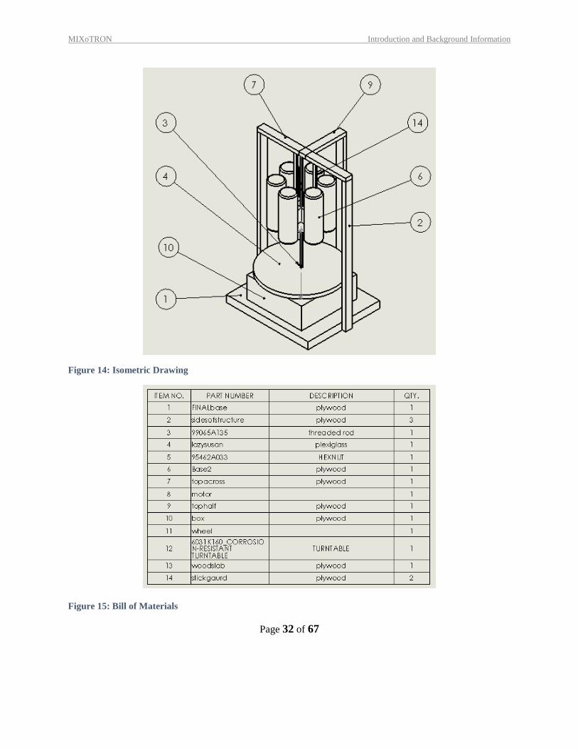
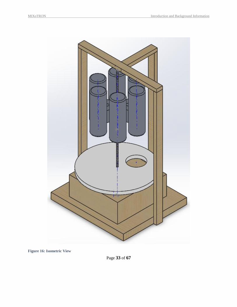
14.1 ISOMETRIC DRAWING WITH BILL OF MATERIALS
The following figures below show the design in multiple different views: isometric, front, side, and top,
as well as an exploded view, created using the functionalities of Solidworks. There is also a bill of
materials, as provided by Solidworks.
MIXoTRON Introduction and Background Information
Page 32 of 67
Figure 14: Isometric Drawing
Figure 15: Bill of Materials
MIXoTRON Introduction and Background Information
Page 33 of 67
Figure 16: Isometric View
MIXoTRON Introduction and Background Information
Page 34 of 67
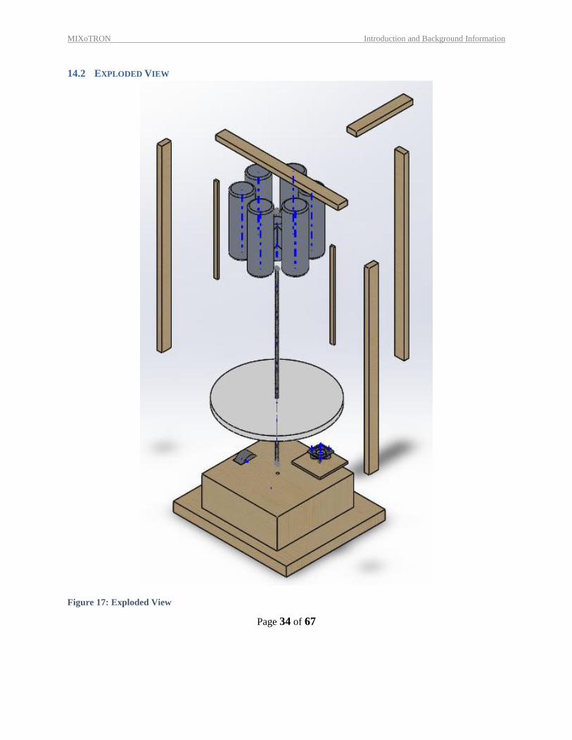
14.2 EXPLODED VIEW
Figure 17: Exploded View
MIXoTRON Introduction and Background Information
Page 35 of 67
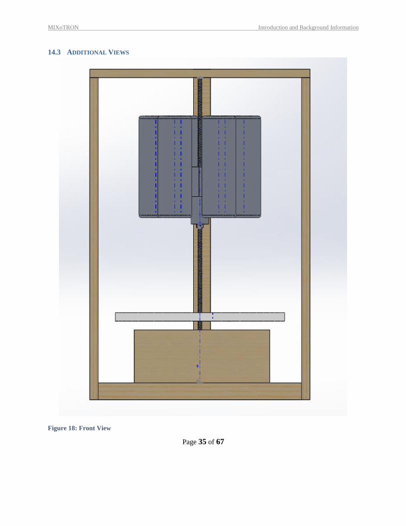
14.3 ADDITIONAL VIEWS
Figure 18: Front View
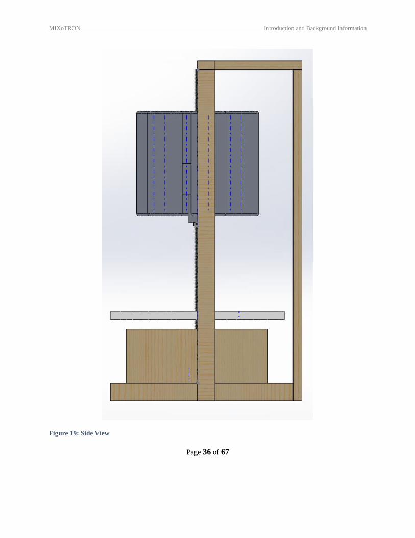
MIXoTRON Introduction and Background Information
Page 36 of 67
Figure 19: Side View
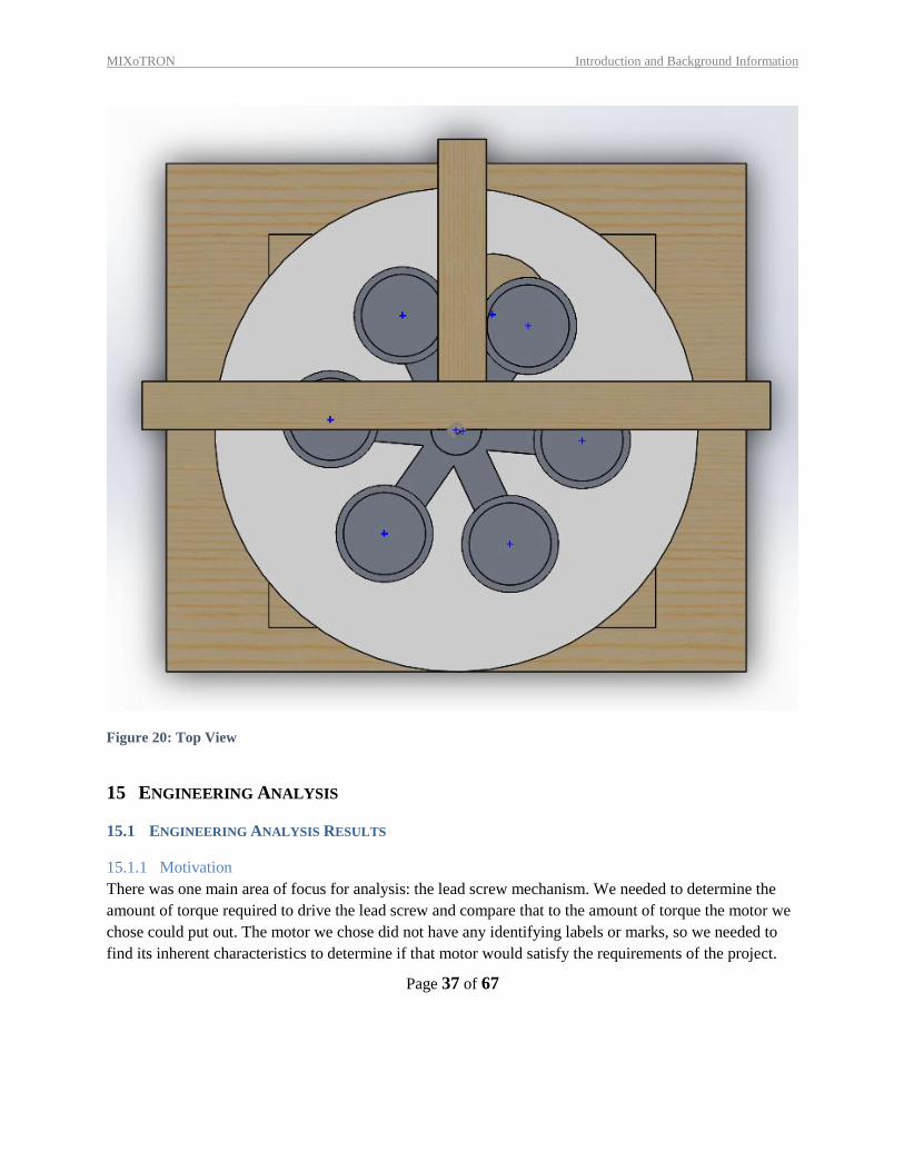
MIXoTRON Introduction and Background Information
Page 37 of 67
Figure 20: Top View
15 ENGINEERING ANALYSIS
15.1 ENGINEERING ANALYSIS RESULTS
15.1.1 Motivation
There was one main area of focus for analysis: the lead screw mechanism. We needed to determine the
amount of torque required to drive the lead screw and compare that to the amount of torque the motor we
chose could put out. The motor we chose did not have any identifying labels or marks, so we needed to
find its inherent characteristics to determine if that motor would satisfy the requirements of the project.
MIXoTRON Introduction and Background Information
Page 38 of 67
15.1.2 Summary Statement of the Analysis
The engineering analysis of the lead screw mechanism was done by pen-to-paper calculations. To
summarize, we experimentally found the stall torque of the motor chosen to drive the lead screw,
calculated the torque required to drive the lead screw with the applied load, found the gear ratio needed to
allow the chosen motor to meet the requirements of the project, and compared the calculated ideal speed
of the lead screw to the actual speed observed during product testing.
Finding the torque required to drive the lead screw was the most important step in the engineering
analysis. Upon researching the lead screw mechanism, we found that the torque required to drive the lead
screw is simply the torque required to lift the load a given distance (lead). The raise torque was found
using the following equation from Machine Design, 4ed [1].
[1]
where F is the load, dm is the mean diameter, L is the lead, and μ is the coefficient of friction between, in
our case, the steel nut and the steel lead screw.
With further research, we found that there is a critical speed at which a lead screw can be driven.
Common practice is to run the lead screw at maximum 80% of the critical speed. We needed to determine
whether our performance goals required driving our lead screw mechanism at greater than 80% of the
critical speed. This was done using the following equation, also from Machine Design, 4ed [1].
[2]
where dm is the mean diameter, L is the lead, and C is the constant describing how the lead screw is fixed.
In our lead screw mechanism, we chose a “simple-simple” support for the lead screw.
The only other equations used in this analysis were basic gear ratio relationships, as seen below.
[3]
where T is torque, ω is the rotational speed, and #teeth is the number of teeth on the gear, while the
subscript “in” represents the input gear on the motor and the subscript “out” represents the output gear on
the lead screw.
15.1.3 Methodology
There were many steps involved in analyzing the lead screw mechanism. First, we found the stall torque
of the motor chosen to drive the lead screw. This was done using a torque gauge borrowed from the
MIXoTRON Introduction and Background Information
Page 39 of 67
Washington University ESE department. Five measurements of the stall torque were taken at two
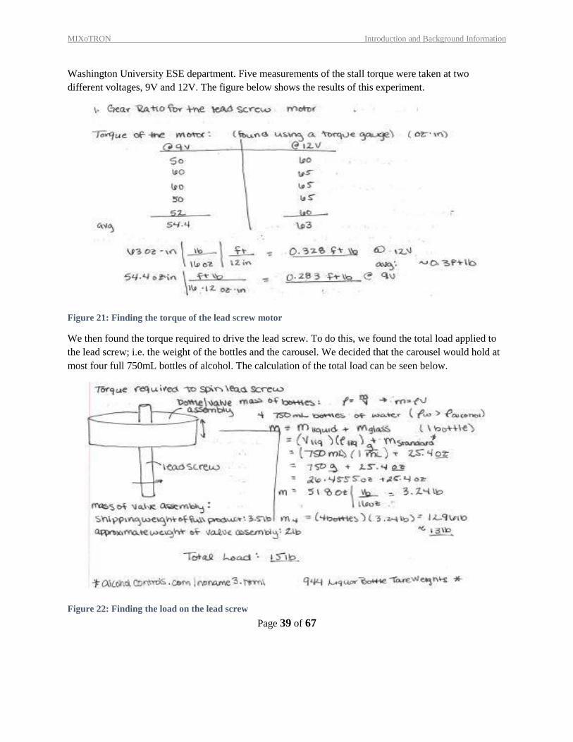
different voltages, 9V and 12V. The figure below shows the results of this experiment.
Figure 21: Finding the torque of the lead screw motor
We then found the torque required to drive the lead screw. To do this, we found the total load applied to
the lead screw; i.e. the weight of the bottles and the carousel. We decided that the carousel would hold at
most four full 750mL bottles of alcohol. The calculation of the total load can be seen below.
Figure 22: Finding the load on the lead screw
MIXoTRON Introduction and Background Information
Page 40 of 67
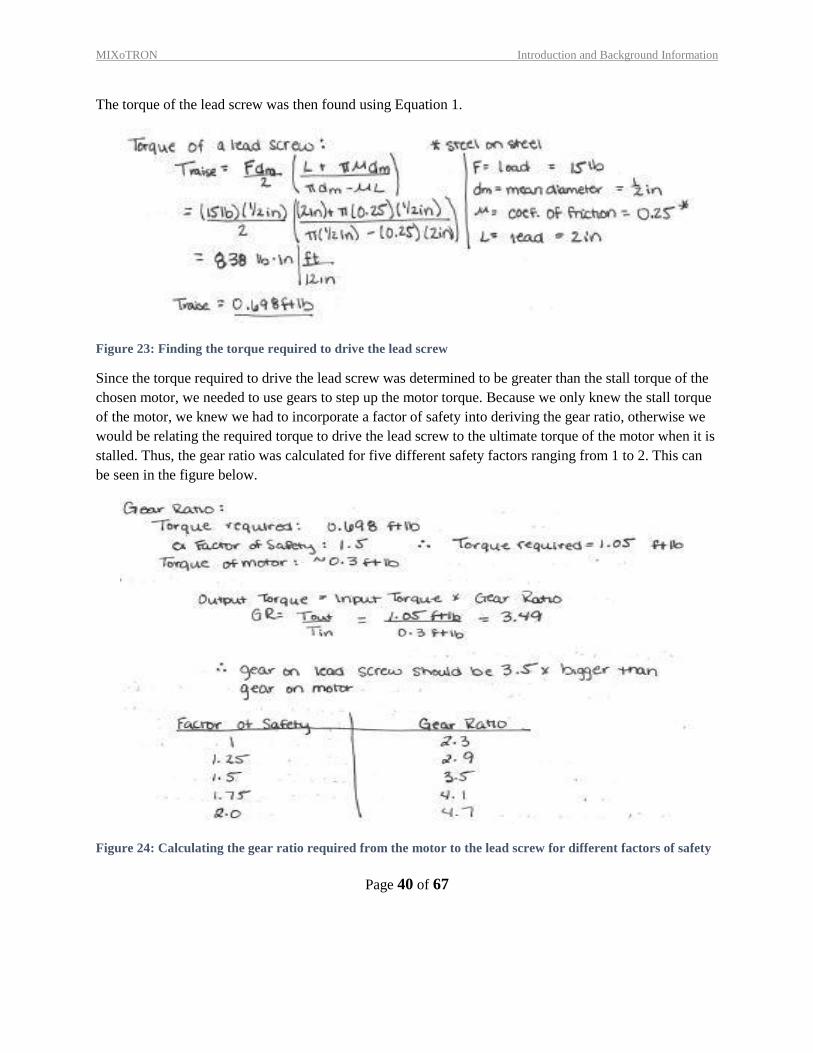
The torque of the lead screw was then found using Equation 1.
Figure 23: Finding the torque required to drive the lead screw
Since the torque required to drive the lead screw was determined to be greater than the stall torque of the
chosen motor, we needed to use gears to step up the motor torque. Because we only knew the stall torque
of the motor, we knew we had to incorporate a factor of safety into deriving the gear ratio, otherwise we
would be relating the required torque to drive the lead screw to the ultimate torque of the motor when it is
stalled. Thus, the gear ratio was calculated for five different safety factors ranging from 1 to 2. This can
be seen in the figure below.
Figure 24: Calculating the gear ratio required from the motor to the lead screw for different factors of safety
MIXoTRON Introduction and Background Information
Page 41 of 67
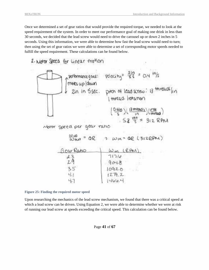
Once we determined a set of gear ratios that would provide the required torque, we needed to look at the
speed requirement of the system. In order to meet our performance goal of making one drink in less than
30 seconds, we decided that the lead screw would need to drive the carousel up or down 2 inches in 5
seconds. Using this information, we were able to determine how fast the lead screw would need to turn;
then using the set of gear ratios we were able to determine a set of corresponding motor speeds needed to
fulfill the speed requirement. These calculations can be found below.
Figure 25: Finding the required motor speed
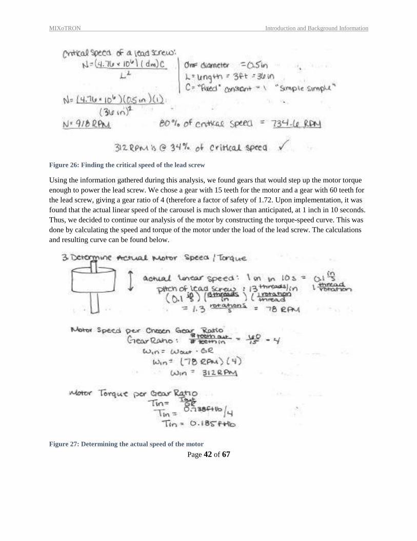
Upon researching the mechanics of the lead screw mechanism, we found that there was a critical speed at
which a lead screw can be driven. Using Equation 2, we were able to determine whether we were at risk
of running our lead screw at speeds exceeding the critical speed. This calculation can be found below.
MIXoTRON Introduction and Background Information
Page 42 of 67
Figure 26: Finding the critical speed of the lead screw
Using the information gathered during this analysis, we found gears that would step up the motor torque
enough to power the lead screw. We chose a gear with 15 teeth for the motor and a gear with 60 teeth for
the lead screw, giving a gear ratio of 4 (therefore a factor of safety of 1.72. Upon implementation, it was
found that the actual linear speed of the carousel is much slower than anticipated, at 1 inch in 10 seconds.
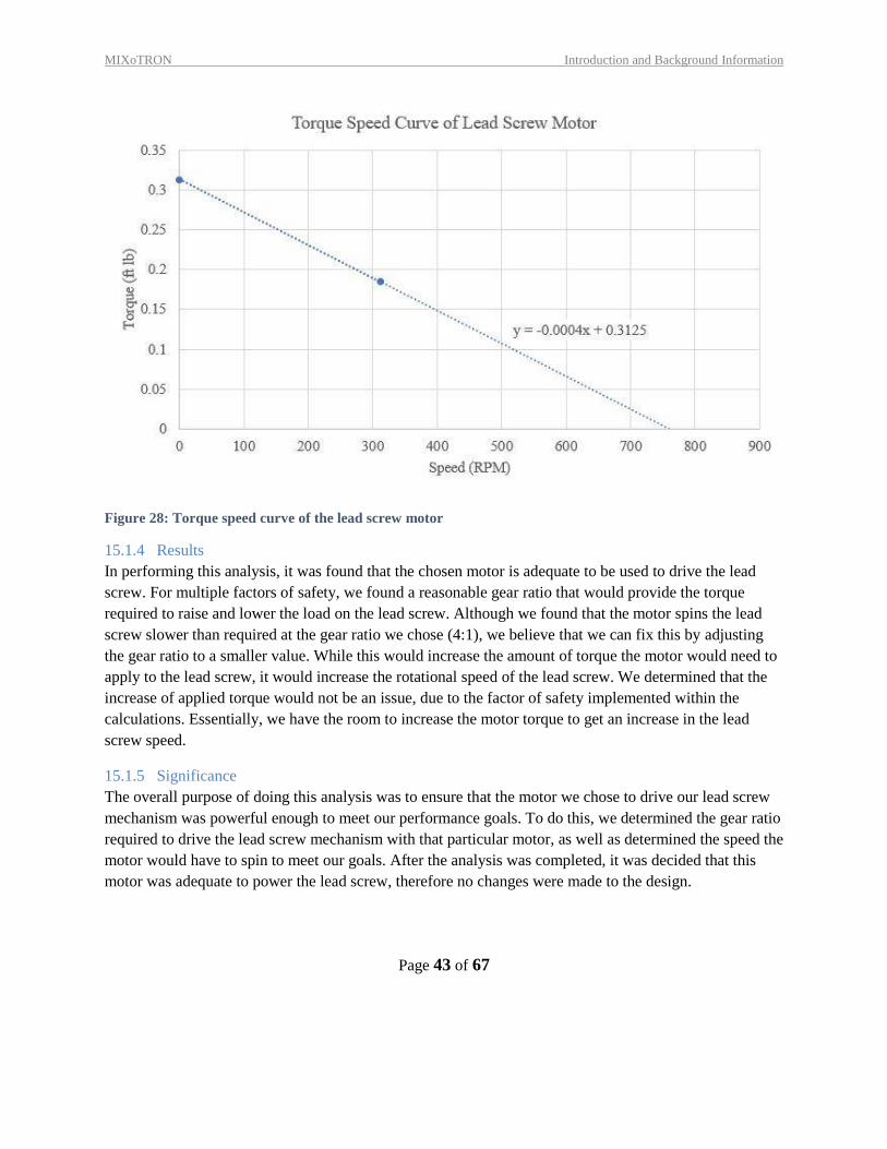
Thus, we decided to continue our analysis of the motor by constructing the torque-speed curve. This was
done by calculating the speed and torque of the motor under the load of the lead screw. The calculations
and resulting curve can be found below.
Figure 27: Determining the actual speed of the motor
MIXoTRON Introduction and Background Information
Page 43 of 67
Figure 28: Torque speed curve of the lead screw motor
15.1.4 Results
In performing this analysis, it was found that the chosen motor is adequate to be used to drive the lead
screw. For multiple factors of safety, we found a reasonable gear ratio that would provide the torque
required to raise and lower the load on the lead screw. Although we found that the motor spins the lead
screw slower than required at the gear ratio we chose (4:1), we believe that we can fix this by adjusting
the gear ratio to a smaller value. While this would increase the amount of torque the motor would need to
apply to the lead screw, it would increase the rotational speed of the lead screw. We determined that the
increase of applied torque would not be an issue, due to the factor of safety implemented within the
calculations. Essentially, we have the room to increase the motor torque to get an increase in the lead
screw speed.
15.1.5 Significance
The overall purpose of doing this analysis was to ensure that the motor we chose to drive our lead screw
mechanism was powerful enough to meet our performance goals. To do this, we determined the gear ratio
required to drive the lead screw mechanism with that particular motor, as well as determined the speed the
motor would have to spin to meet our goals. After the analysis was completed, it was decided that this
motor was adequate to power the lead screw, therefore no changes were made to the design.
MIXoTRON Introduction and Background Information
Page 44 of 67
15.2 PRODUCT RISK ASSESSMENT
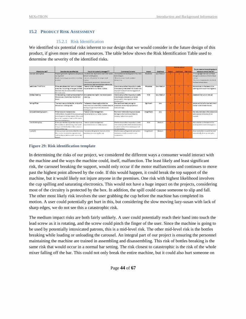
15.2.1 Risk Identification
We identified six potential risks inherent to our design that we would consider in the future design of this
product, if given more time and resources. The table below shows the Risk Identification Table used to
determine the severity of the identified risks.
Figure 29: Risk identification template
In determining the risks of our project, we considered the different ways a consumer would interact with
the machine and the ways the machine could, itself, malfunction. The least likely and least significant
risk, the carousel breaking the support, would only occur if the motor malfunctions and continues to move
past the highest point allowed by the code. If this would happen, it could break the top support of the
machine, but it would likely not injure anyone in the premises. One risk with highest likelihood involves
the cup spilling and saturating electronics. This would not have a huge impact on the projects, considering
most of the circuitry is protected by the box. In addition, the spill could cause someone to slip and fall.
The other most likely risk involves the user grabbing the cup before the machine has completed its
motion. A user could potentially get hurt in this, but considering the slow moving lazy-susan with lack of
sharp edges, we do not see this a catastrophic risk.
The medium impact risks are both fairly unlikely. A user could potentially reach their hand into touch the
lead screw as it is rotating, and the screw could pinch the finger of the user. Since the machine is going to
be used by potentially intoxicated patrons, this is a mid-level risk. The other mid-level risk is the bottles
breaking while loading or unloading the carousel. An integral part of our project is ensuring the personnel
maintaining the machine are trained in assembling and disassembling. This risk of bottles breaking is the
same risk that would occur in a normal bar setting. The risk closest to catastrophic is the risk of the whole
mixer falling off the bar. This could not only break the entire machine, but it could also hurt someone on
MIXoTRON Introduction and Background Information
Page 45 of 67
the way down. Since the machine is so heavy and the base is so big, it is pretty unlikely that this will
happen.
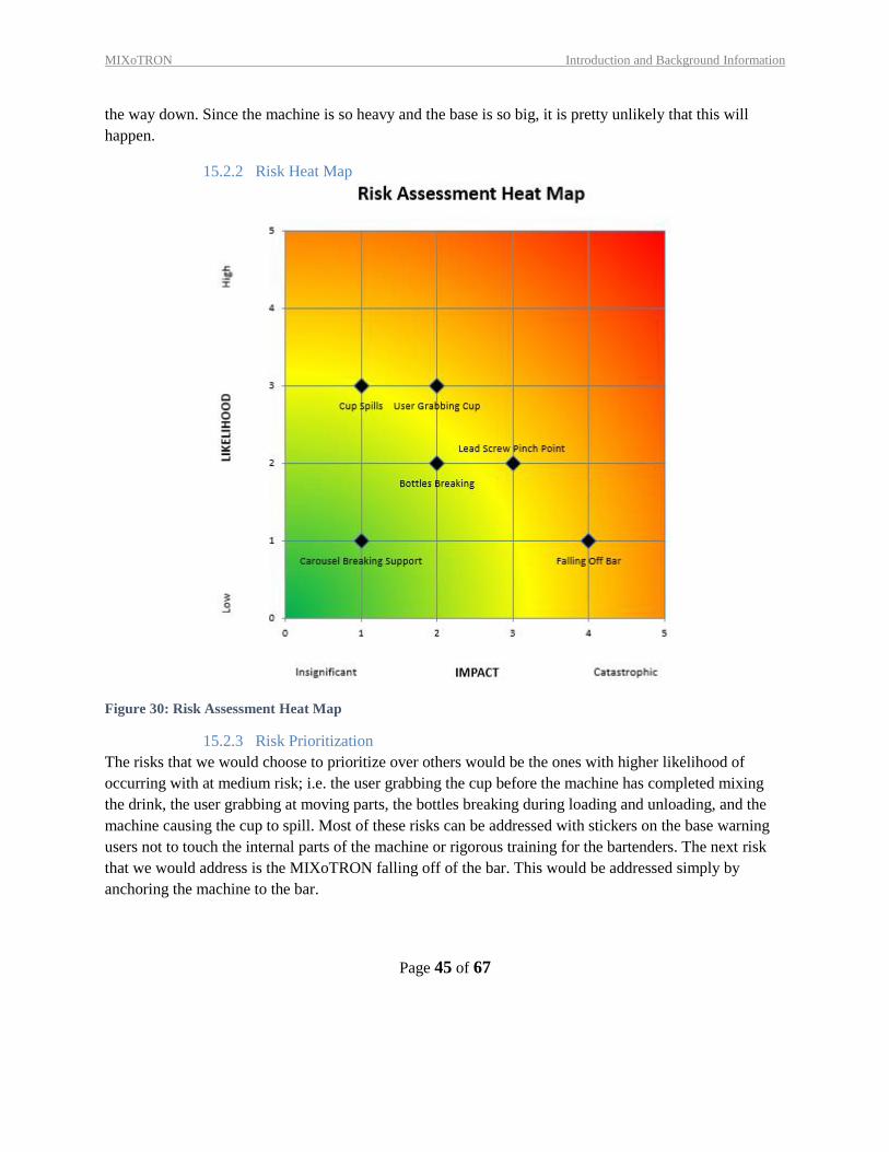
15.2.2 Risk Heat Map
Figure 30: Risk Assessment Heat Map
15.2.3 Risk Prioritization
The risks that we would choose to prioritize over others would be the ones with higher likelihood of
occurring with at medium risk; i.e. the user grabbing the cup before the machine has completed mixing
the drink, the user grabbing at moving parts, the bottles breaking during loading and unloading, and the
machine causing the cup to spill. Most of these risks can be addressed with stickers on the base warning
users not to touch the internal parts of the machine or rigorous training for the bartenders. The next risk
that we would address is the MIXoTRON falling off of the bar. This would be addressed simply by
anchoring the machine to the bar.
MIXoTRON Introduction and Background Information
Page 46 of 67
16 DESIGN DOCUMENTATION
16.1 PERFORMANCE GOALS
There are five performance goals for this project that will determine the success of the project. These
performance goals are as follows:
1. The MIXoTRON will make one mixed drink in less than 30 seconds.
2. The MIXoTRON will make 20 drinks before switching batteries.
3. The MIXoTRON will be able to be disassembled and reassembled in less than 5 minutes by
trained personnel for basic cleaning and minor maintenance.
4. The MIXoTRON will be able to make 5 different cocktails.
5. The MIXoTRON will be able to make 8 drinks without manually centering.
16.2 WORKING PROTOTYPE DEMONSTRATION
16.2.1 Performance Evaluation
To evaluate the success of our project we either tested or analyzed each performance goal.
On average, it took the prototype one minute and thirty seconds to make one drink. This is three times as
long as we had hoped for, therefore our prototype has failed performance goal one by our original standards.
However, we also wanted to compare our prototype against the average bartender to see how our design
compares. During research and customer interviews we found that it takes the average bartender roughly
one minute to make a more complex cocktail than just a mixture of two ingredients. Thus, our prototype is
still unsuccessful in comparison. There are a few ways we could speed up the device. First, we could
redesign the gears on the lead screw so that the gear ratio is numerically closer to one. This would step
down the torque, but would increase the speed of the lead screw. We could also use a lead screw with a
steeper thread pitch, or simply buy a more powerful motor.
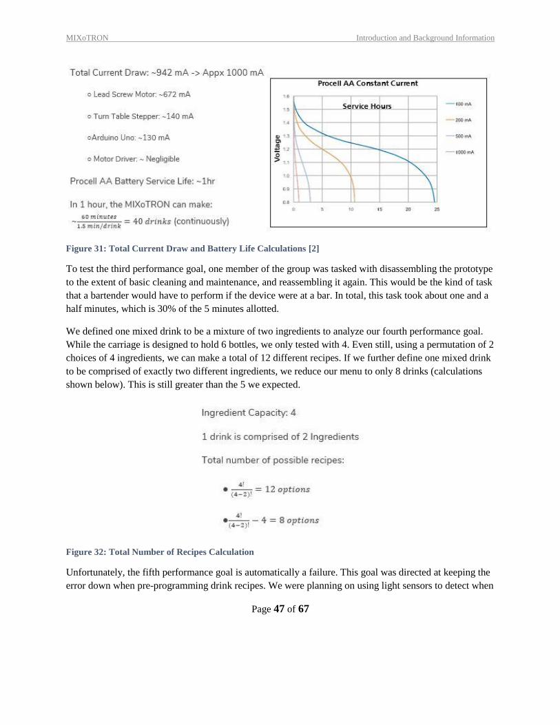
To analyze our second performance goal, we found the total current draw of each electrical element used
to power the device. The total current draw of our prototype is roughly 1A (a breakdown of the calculations
can be found below). Our prototype is currently powered by 8 AA batteries connected in series to provide
a total voltage of 12V. We found a lifecycle chart of Procell AA batteries providing a constant current. Our
prototype would follow the 1000mA curve designated in red on this chart, which corresponds to a service
life of roughly 1 hour of continuous use. Knowing that our device can make one drink in 1.5 minutes, we
estimate that the prototype can make 40 drinks before having to switch batteries.
MIXoTRON Introduction and Background Information
Page 47 of 67
Figure 31: Total Current Draw and Battery Life Calculations [2]
To test the third performance goal, one member of the group was tasked with disassembling the prototype
to the extent of basic cleaning and maintenance, and reassembling it again. This would be the kind of task
that a bartender would have to perform if the device were at a bar. In total, this task took about one and a
half minutes, which is 30% of the 5 minutes allotted.
We defined one mixed drink to be a mixture of two ingredients to analyze our fourth performance goal.
While the carriage is designed to hold 6 bottles, we only tested with 4. Even still, using a permutation of 2
choices of 4 ingredients, we can make a total of 12 different recipes. If we further define one mixed drink
to be comprised of exactly two different ingredients, we reduce our menu to only 8 drinks (calculations
shown below). This is still greater than the 5 we expected.
Figure 32: Total Number of Recipes Calculation
Unfortunately, the fifth performance goal is automatically a failure. This goal was directed at keeping the
error down when pre-programming drink recipes. We were planning on using light sensors to detect when
MIXoTRON Introduction and Background Information
Page 48 of 67
the cup was under the correct bottle. We expected a small amount of error in this process, and expected
that the error would accumulate over time, and eventually need to be manually re-centered to keep the
device in working condition. Since we do not have recipes pre-programmed, this goal is untestable.
Overall, we consider this project a qualified success. We have met or exceeded three of the five
performance goals, and have plans to improve upon the two that failed.
16.2.2 Working Prototype – Video Link
Please follow the link below to view the Final Prototype Review video on YouTube:
https://youtu.be/APT1XfQo7AQ
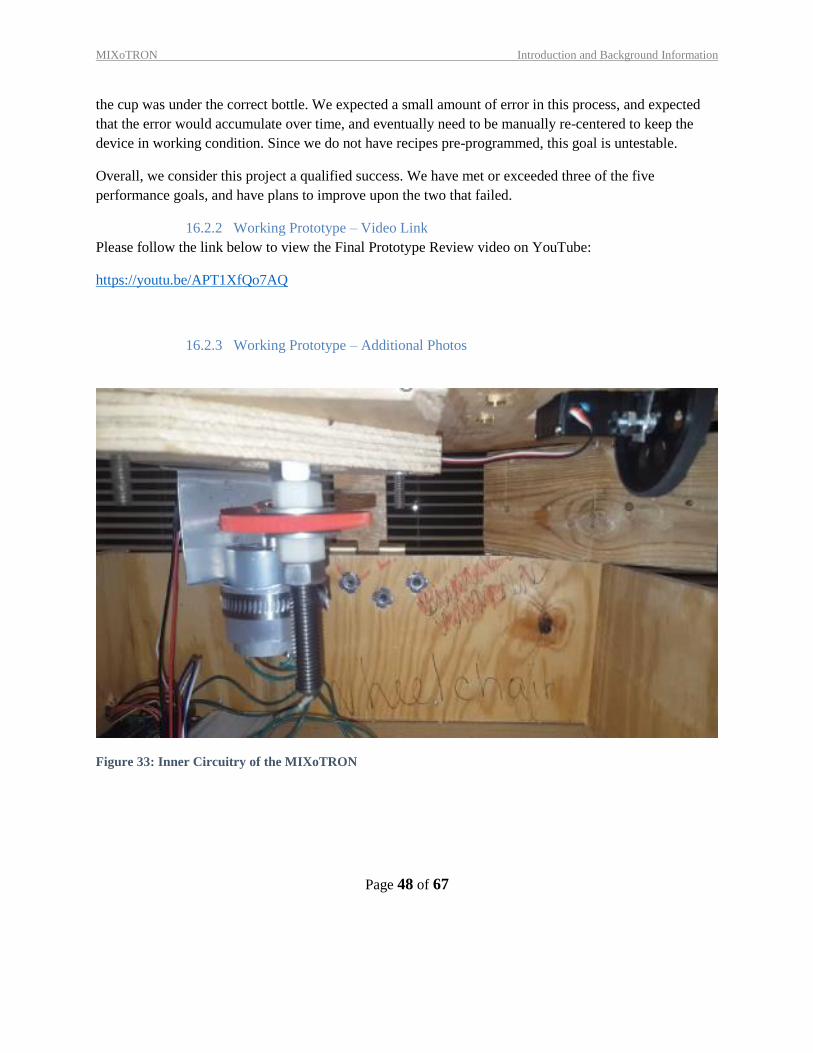
16.2.3 Working Prototype – Additional Photos
Figure 33: Inner Circuitry of the MIXoTRON
MIXoTRON Introduction and Background Information
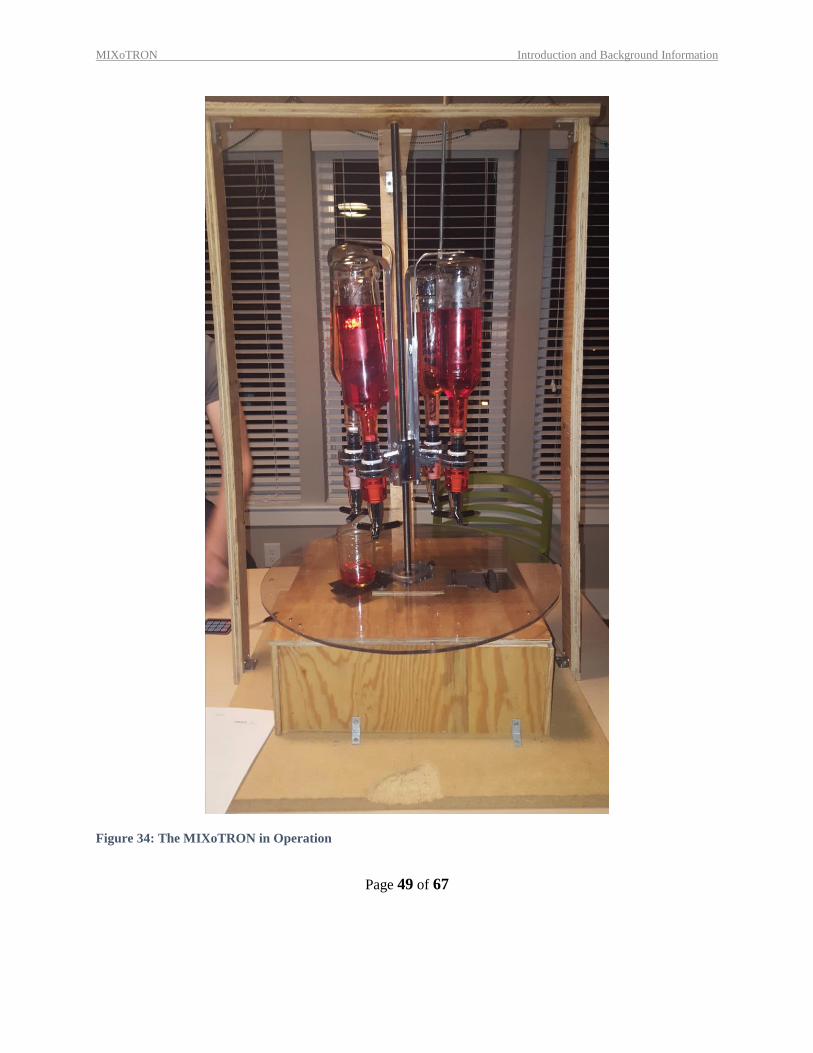
Page 49 of 67
Figure 34: The MIXoTRON in Operation
MIXoTRON Introduction and Background Information
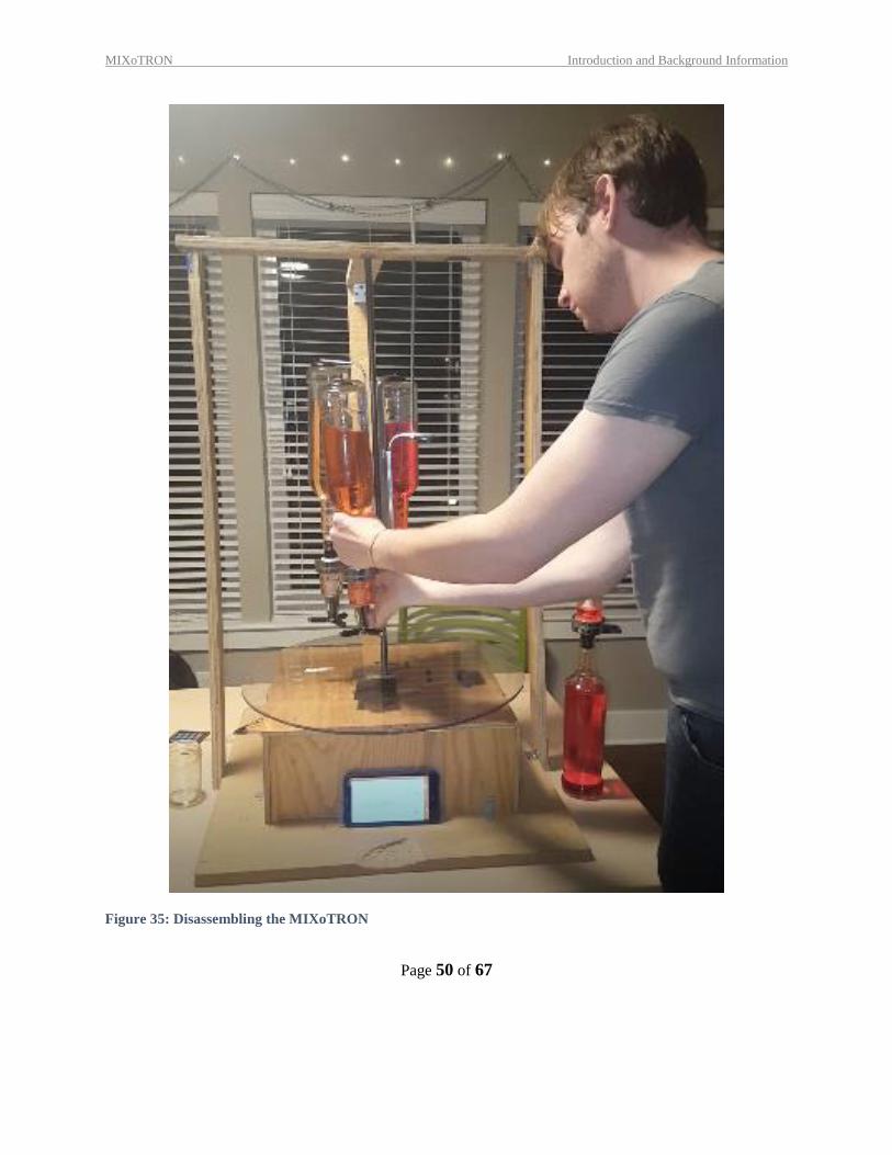
Page 50 of 67
Figure 35: Disassembling the MIXoTRON
MIXoTRON Introduction and Background Information
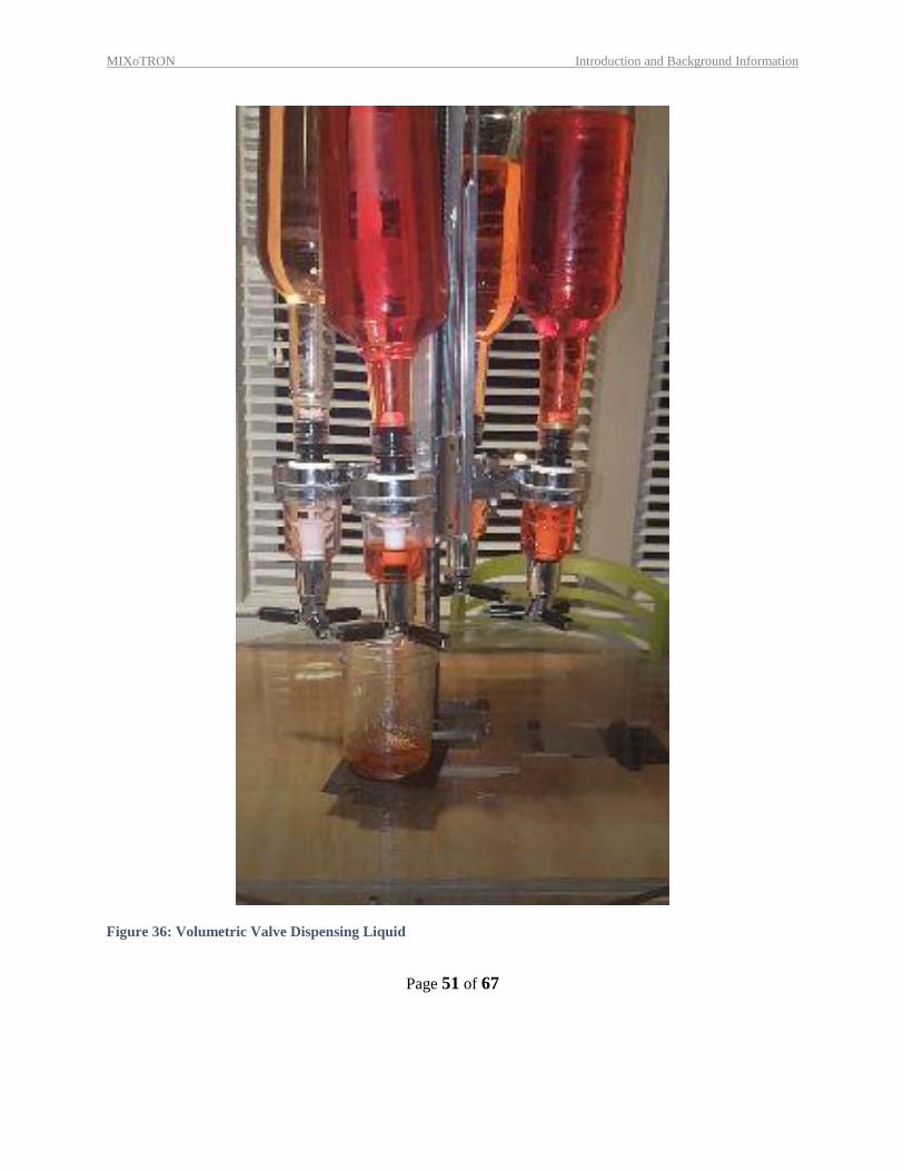
Page 51 of 67
Figure 36: Volumetric Valve Dispensing Liquid
MIXoTRON Introduction and Background Information
Page 52 of 67
17 DISCUSSION
17.1 DESIGN FOR MANUFACTURING – PART REDESIGN FOR INJECTION MOLDING
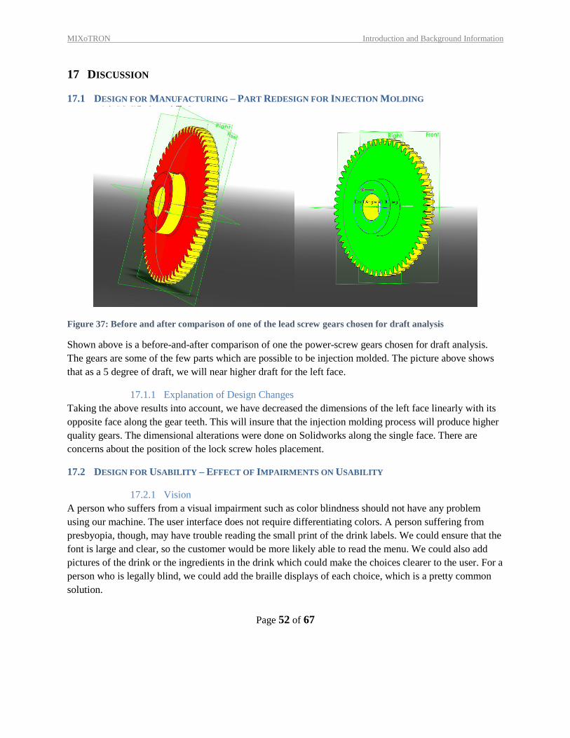
Figure 37: Before and after comparison of one of the lead screw gears chosen for draft analysis
Shown above is a before-and-after comparison of one the power-screw gears chosen for draft analysis.
The gears are some of the few parts which are possible to be injection molded. The picture above shows
that as a 5 degree of draft, we will near higher draft for the left face.
17.1.1 Explanation of Design Changes
Taking the above results into account, we have decreased the dimensions of the left face linearly with its
opposite face along the gear teeth. This will insure that the injection molding process will produce higher
quality gears. The dimensional alterations were done on Solidworks along the single face. There are
concerns about the position of the lock screw holes placement.
17.2 DESIGN FOR USABILITY – EFFECT OF IMPAIRMENTS ON USABILITY
17.2.1 Vision
A person who suffers from a visual impairment such as color blindness should not have any problem
using our machine. The user interface does not require differentiating colors. A person suffering from
presbyopia, though, may have trouble reading the small print of the drink labels. We could ensure that the
font is large and clear, so the customer would be more likely able to read the menu. We could also add
pictures of the drink or the ingredients in the drink which could make the choices clearer to the user. For a
person who is legally blind, we could add the braille displays of each choice, which is a pretty common
solution.
MIXoTRON Introduction and Background Information
Page 53 of 67
17.2.2 Hearing
One of our design decisions was to add a noise when the drink is completed so the user knows the drink is
ready to take out of the holder. We could implement a light that goes off as well when the drink is
finished. There are no other significant noises a user would need to interpret to use the machine
17.2.3 Physical
If a person has a physical handicap requiring a wheelchair, the machine may be too high to reach. This
would mostly be up to the individual bars on where they would place the drink maker. There is not a lot
of physical activity involved in using our machine, just pressing a button and removing the drink.
17.2.4 Language
Our menu used in our machine is completely in English. Similar to the menu suggested in the visual
impairment section, the menu could include pictures of the final drink and the ingredients. We could also
provide additional menus in other common languages that are available for the users to read.
7.2 OVERALL EXPERIENCE
7.2.1 Does your final project result align with the initial project description?
In basic principle our initial design and final product do alight. But the process used to complete the
various required actions (pouring, mixing, choosing drink liquids) all deviate to a degree from our first
conceptualization of the device.
7.2.2 Was the project more or less difficult than you had expected?
The design presented several challenges that were not initially apparent during the planning phase of the
project. These unplanned issues contributed to rapid, minor redesigns and drastically increased the
required manufacturing time at every level.
7.2.3 In what ways do you wish your final prototype would have performed better?
The final design as well as middle stage iterations of the Drink Mixer where limited by requiring certain
components. The need to have a volumetrically accurate drink necessitated the use of a specific
proprietary valve. This valves immutability forced a major redesign of the main assembly. We wish we
could been able to either alter the specifications of the valve or had access to more sophisticated
components that could complete the same task.
7.2.4 your group missing any critical information when you evaluated concepts?
No, we had a strong grasp on the fundamental engineering concepts we would need to produce the final
product. Nearly every issue which arose was due to poor manufacturing tools/components or inaccurate
measurements when performing preliminary analysis.
MIXoTRON Introduction and Background Information
Page 54 of 67
7.2.5 Were there additional engineering analyses that could have helped guide your
design?
A greater detailed descriptor of the volumetric valve would have allowed us to make a better-informed
choice for what design path to take early on in the decision phase. During the early manufacturing phase
several wooden pieces were destroyed by pressure from other components. Solidworks as available to us
did not have the material properties of the specific type of wood loaded which limited how we could have
planned ahead for such failures.
7.2.6 How did you identify your most relevant codes and standards and how they
influence revision of the design?
After meeting with a representative of the Washington University Engineering library we were directed to
several resources for codes and standards of food dispensing/vending machinery. These resources helped
push us towards streamlining the liquid holding components to help minimize the expense of
manufacturing.
7.2.7 What ethical considerations (from the Engineering Ethics and Design for
Environment seminar) are relevant to your device? How could these
considerations be addressed?
The main design choice we made based on ethical concerns were concerned with using recycled
materials. Nearly every component used in the MIXoTRON was taken from prior existing assemblies.
The only exceptions where the rotation plexiglass plate, gears, and some fasteners.
7.2.8 On which part(s) of the design process should your group have spent more time?
Which parts required less time?
The configuring of our physical frame and motor required more time than expected. Conversely the code
writing to control the drinks production required less time to solve, as well as less time than was expected
by a large margin.
7.2.9 Was there a task on your Gantt chart that was much harder than expected? Were
there any that were much easier?
The drive screw and turn table both required significantly more work than initially expected. We had
anticipated needing only a week to meet minimum movement requirements with the remaining weeks to
be used enhancing the prototypes aesthetic qualities and movement speed. Most of this time instead was
consumed getting the model to the acceptable level.
7.2.10 Was there a component of your prototype that was significantly easier or harder to
make/assemble than you expected?
Due to limitations in the facilities made available to use for manufacturing, the electronics box and turn
table where harder to shape than what would have seemed reasonable beforehand. The provided cutting
equipment where generically less accurate than what was needed, and this great care had to be taken
during the shaping process.
MIXoTRON Introduction and Background Information
Page 55 of 67
7.2.11 If your budget were increased to 10x its original amount, would your approach
have changed? If so, in what specific ways?
Yes, several ideas were scrapped due to cost of producing. The largest divergence would be in using an
electronic sensor to measure the volume of dispensed liquids. The specific method of volume measuring
used in our final design greatly restricted other aspects of the drink mixers design.
7.2.12 If you were able to take the course again with the same project and group, what
would you have done differently the second time around?
If we were to redo this project the first and major change we would make would be the breath of actions
we wanted the Mixer to achieve. Throughout the entire semester we were forced to shave and refine
exactly what we expected from the finish produce based on limited resources and time. If we started with
a simpler goal the final product might have had greater refinement.
7.2.13 Were your team member’s skills complementary?
At least one member had background experience with every aspect of the shaping and assembling process
be it woodworking, metal working, coding, or servo-sensors.
7.2.14 Was any needed skill missing from the group?
As stated above, at least one member was proficient at every stage. What we could have used was
individually or as a group was deeper experience with this specific kind of machine. If we had been more
experienced than several obvious, in hindsight, errors could have been avoided.
7.2.15 Has the project enhanced your design skills?
Yes, we have all gained in-depth experience with the various stages of product design, and more
importantly, manufacturing. Beyond the simple skills of machining and analysis we were also forced to
become more skilled in servo-programing.
7.2.16 Would you now feel more comfortable accepting a design project assignment at a job?
Yes, we would.
7.2.17 Are there projects you would attempt now that you would not have attempted before?
As a group, we feel that we will now be able to take on projects with more confidence and more of a
directive to make decisions on our own. In many
MIXoTRON Introduction and Background Information
Page 56 of 67
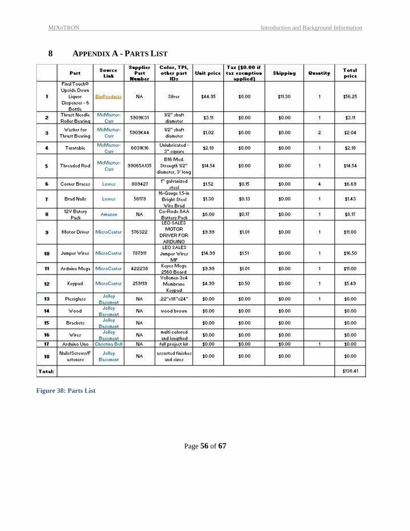
8 APPENDIX A - PARTS LIST
Figure 38: Parts List
MIXoTRON Introduction and Background Information
Page 57 of 67
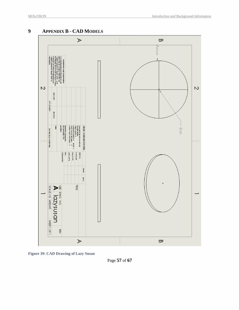
9 APPENDIX B - CAD MODELS
Figure 39: CAD Drawing of Lazy Susan
MIXoTRON Introduction and Background Information
Page 58 of 67
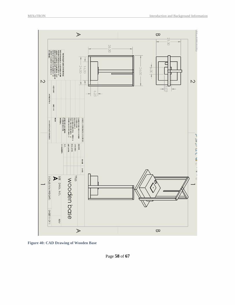
Figure 40: CAD Drawing of Wooden Base
MIXoTRON Introduction and Background Information
Page 59 of 67
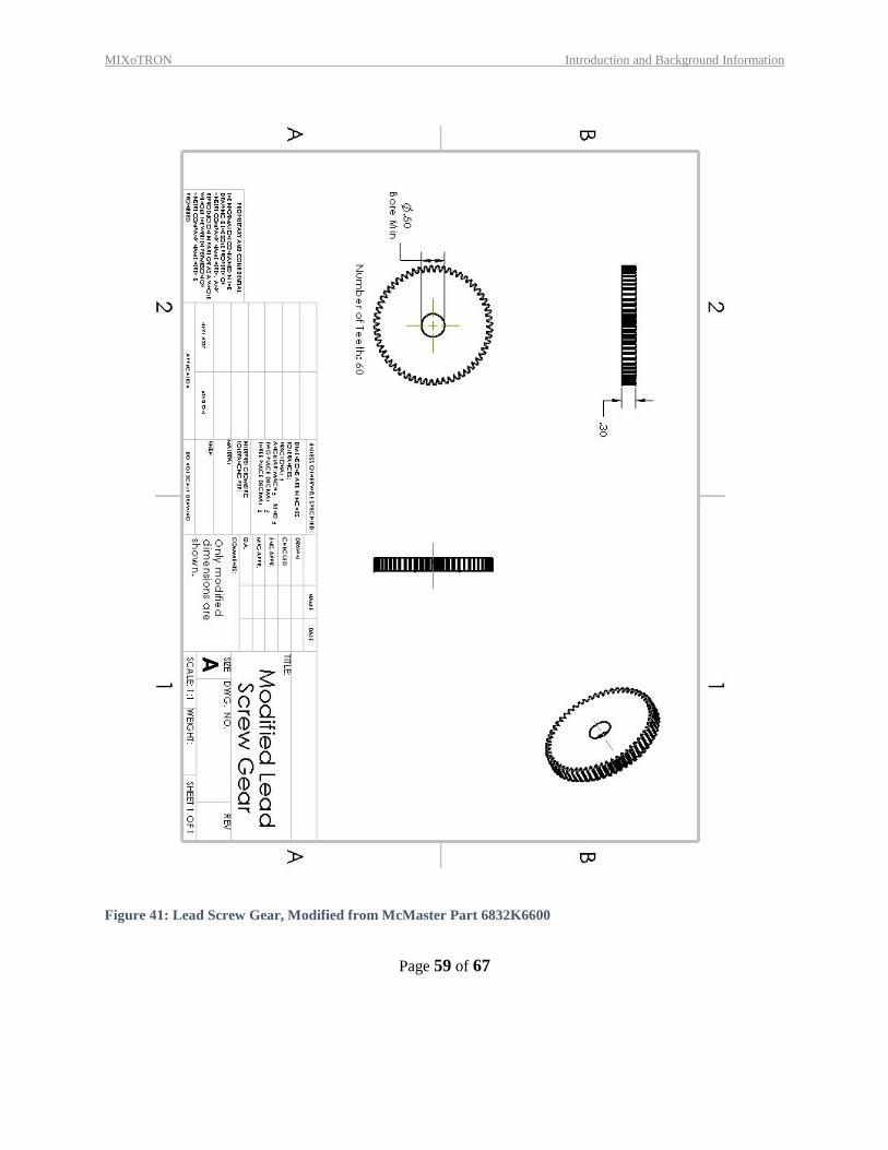
Figure 41: Lead Screw Gear, Modified from McMaster Part 6832K6600
MIXoTRON Introduction and Background Information
Page 60 of 67
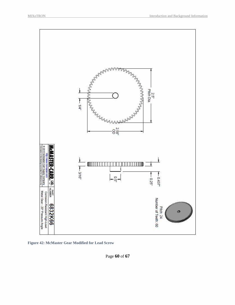
Figure 42: McMaster Gear Modified for Lead Screw
MIXoTRON Introduction and Background Information
Page 61 of 67
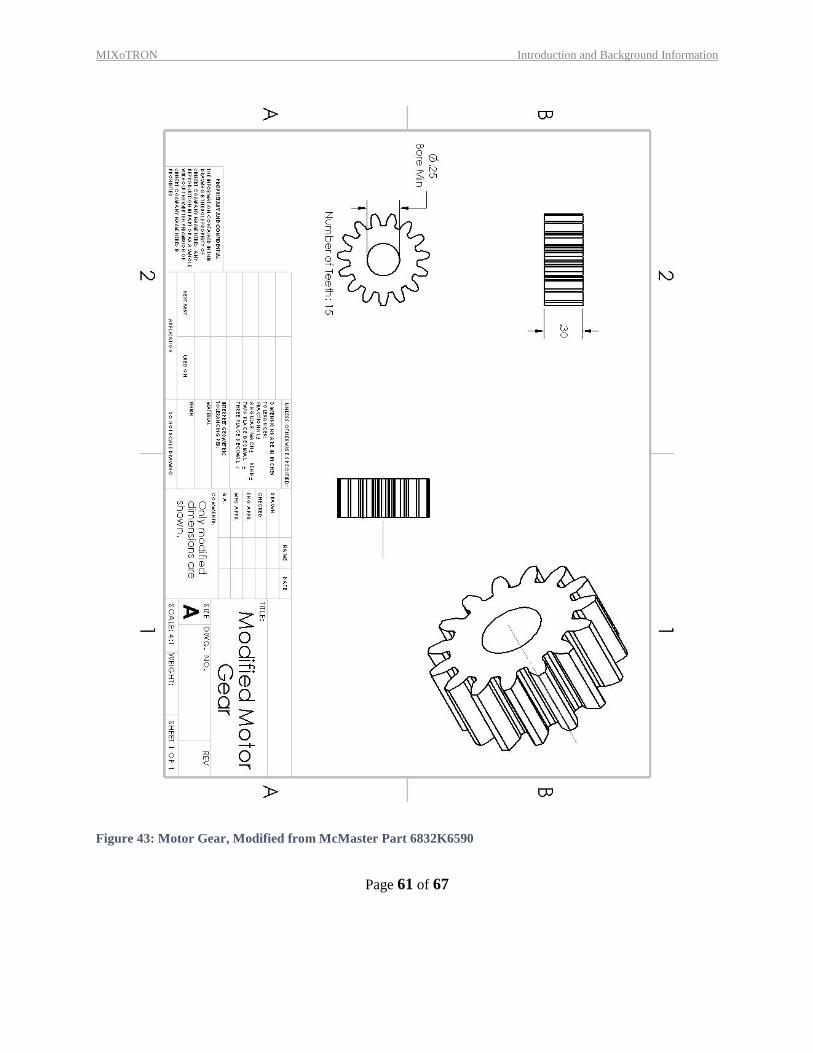
Figure 43: Motor Gear, Modified from McMaster Part 6832K6590
MIXoTRON Introduction and Background Information
Page 62 of 67
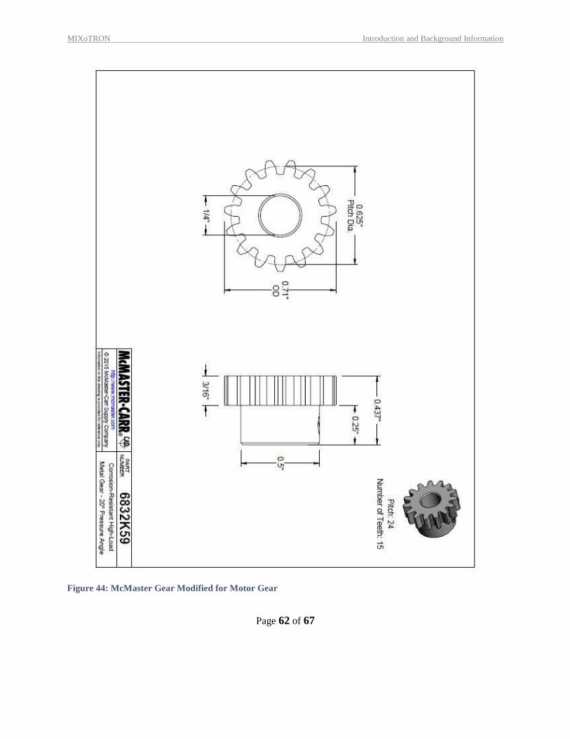
Figure 44: McMaster Gear Modified for Motor Gear
MIXoTRON Introduction and Background Information
Page 63 of 67
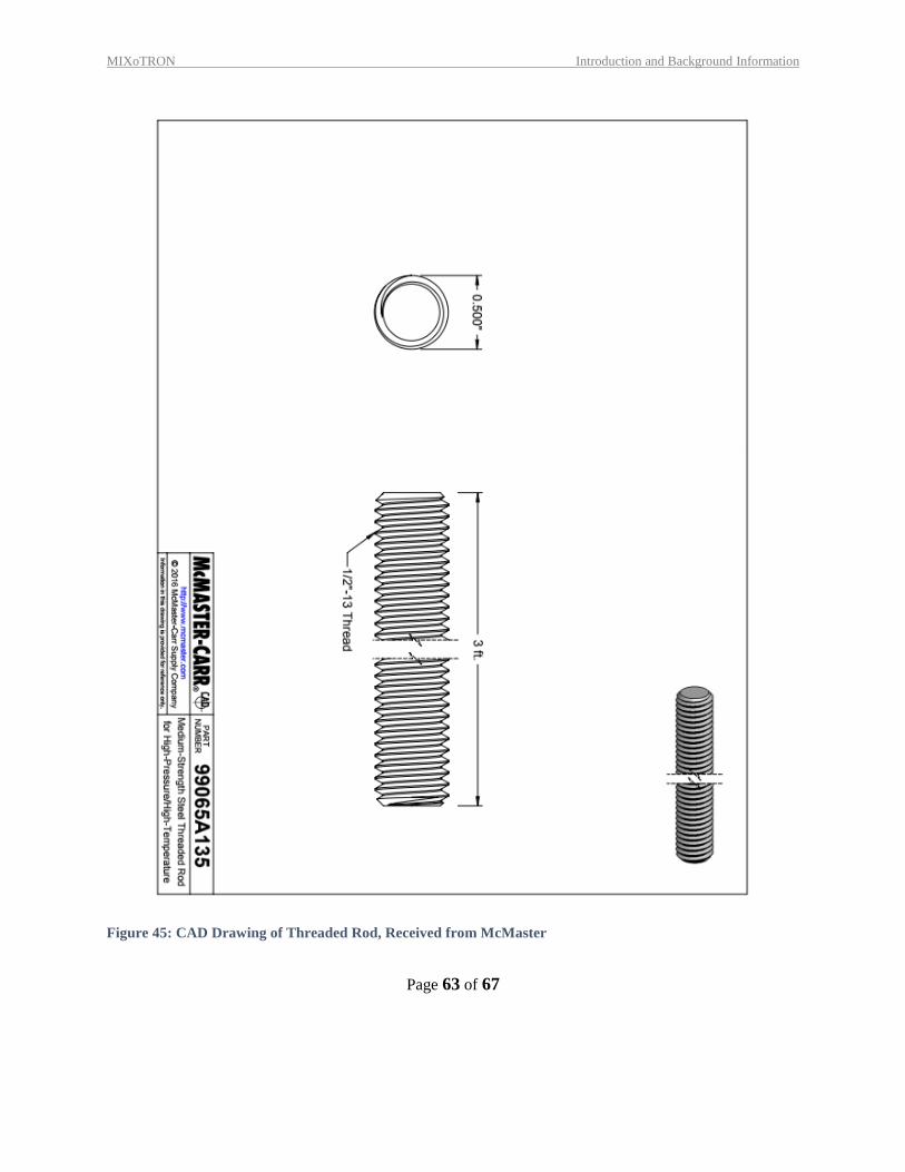
Figure 45: CAD Drawing of Threaded Rod, Received from McMaster
MIXoTRON Introduction and Background Information
Page 64 of 67
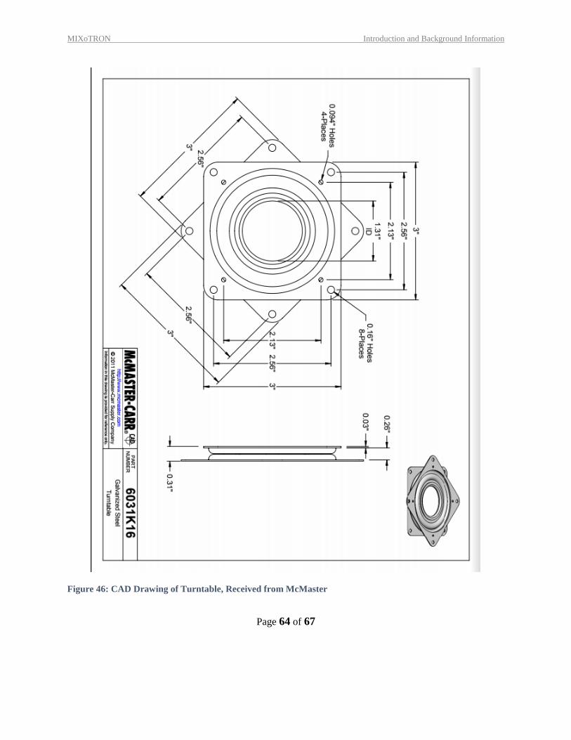
Figure 46: CAD Drawing of Turntable, Received from McMaster
MIXoTRON Introduction and Background Information
Page 65 of 67
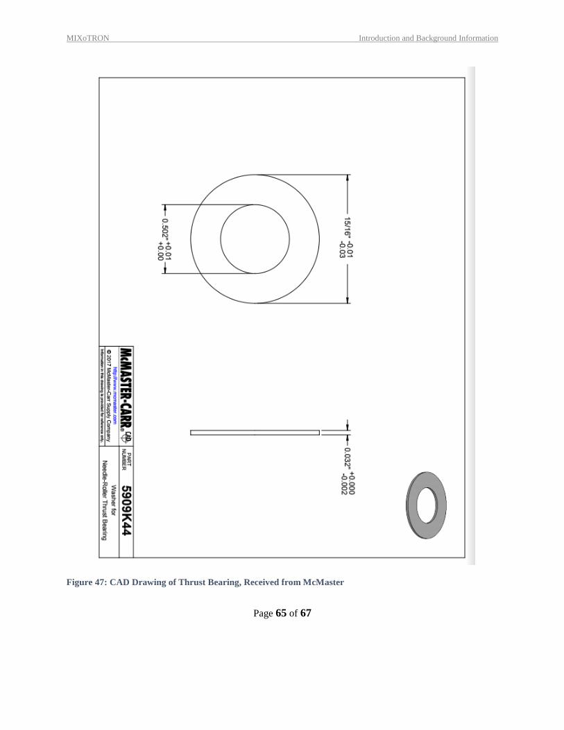
Figure 47: CAD Drawing of Thrust Bearing, Received from McMaster
MIXoTRON Introduction and Background Information
Page 66 of 67
10 ANNOTATED BIBLIOGRAPHY
[1] R. L. Norton, Machine Design, an Integrated Approach, 4th ed., Worcester, MA: Prentice Hall, 2011.
[2] "Duracell Technical Library," Duracell, 2016. [Online]. Available:
https://d2ei442zrkqy2u.cloudfront.net/wp-content/uploads/2016/03/PC15US12141.pdf.