Solar Irrigation Pumps in India: Can Electicity Buy-Back Curb Groundwater Over-use?

MVP IV Series Groundwater Pumps
User Manual
Version 2.2
Durham Geo Slope Indicator 2175 West Park Court Stone Mountain, GA 30087 USA
Phone: 800-837-0864 or +1.770.465.7557 Fax: 770.465.7447
e-mail: [email protected] www.DurhamGeo.com

Page 2 of 24
Disclaimer Durham Geo-Enterprises, Inc. (including all affiliates to include its trade name of DGSI) makes no representations or warranties with respect to the contents hereof and specifically disclaim any implied warranties of merchantability or fitness for any particular purpose. Durham Geo Slope Indicator reserves the right to revise this publication and to make changes from time to time in its content without obligations to notify any person or organization of such revision or changes.
Information Record
Model #: ____________ Serial #: ______________ Sold By: ___________________ Date Purchased: _____________ The serial number for the pump is listed on the side of the pump head. You will need this number if you call DGSI for service or support.
IMPORTANT Before beginning installation procedures, these Installation and Operating Instructions should be studied carefully. The installation and operation should also be in accordance with local regulations and accepted codes of good practice.

Page 3 of 24
Table of Contents IMPORTANT SAFETY INSTRUCTIONS ..................................................................................................... 4 RECEIVING .................................................................................................................................................. 5
1.0 Models Covered ............................................................................................................................. 5 2.0 Receiving Procedures .................................................................................................................... 5 3.0 Typical MVP System Components................................................................................................. 5 4.0 Unpacking....................................................................................................................................... 6
OPERATING PRINCIPLES .......................................................................................................................... 7 1.0 Application ...................................................................................................................................... 7 2.0 Principles of Operation ................................................................................................................... 7 3.0 MVP Pump Configurations ............................................................................................................. 7
INSTALLATION AND OPERATION ............................................................................................................ 8 1.0 Installation tips ................................................................................................................................ 8 2.0 Connecting the Pump ..................................................................................................................... 9 3.0 Connection Above the Well .......................................................................................................... 11 4.0 Activate the system ...................................................................................................................... 12
MAINTENANCE.......................................................................................................................................... 14 1.0 Cleaning the MVP Pump .............................................................................................................. 14 2.0 Checking the Air Valve: ................................................................................................................ 15 3.0 Recommended Repair parts......................................................................................................... 16
TROUBLESHOOTING................................................................................................................................ 17 1.0 Problem: Pump Not Operating ..................................................................................................... 17 2.0 Problem: Pump blowing air into fluid discharge line momentarily at end of pump cycle.............. 17 3.0 Problem: Air coming from exhaust line continuously. Pump not operating.................................. 17 4.0 Problem: Pump blowing air into discharge line continuously. ...................................................... 17 5.0 Problem: Air blowing up the well continuously. ............................................................................ 17 6.0 Returning Equipment for Service.................................................................................................. 18
LIMITED WARRANTY................................................................................................................................ 19 APPENDIX A .............................................................................................................................................. 20
1.0 Air Consumption ........................................................................................................................... 20 APPENDIX B .............................................................................................................................................. 21
1.0 General MVP Specifications......................................................................................................... 21 APPENDIX C .............................................................................................................................................. 22
1.0 Air Purge Line............................................................................................................................... 22 APPENDIX D .............................................................................................................................................. 24
1.0 Decontamination Certificate ......................................................................................................... 24

M V P P U M P S I M P O R T A N T S A F E T Y I N S T R U C T I O N S
Page 4 of 24
IMPORTANT SAFETY INSTRUCTIONS
Safety is a priority in the design of our remediation equipment. This manual highlights the areas that are important when you install and use this equipment. Following is a partial list of safety procedures:
Wear chemically resistant clothing
Wear safety goggles to protect your eyes
Point air and discharge hoses away form your person and other personnel
Turn off the air supply to the pump prior to service
Avoid the pinch points during assembly and disassembly of the pumps
Properly protect air supply and fluid discharge hoses from damage
WARNING!
Any electrical components used in an explosive atmosphere must be located in compliance with Chapter 5 of the National Electrical Code and any other local codes. This applies to electrically powered air compressors as well.

M V P P U M P S R E C E I V I N G
Page 5 of 24
RECEIVING To insure optimum performance it is strongly suggested that the operators read the manual prior to using the MVP Pumps. Failure to follow the installation and operation instructions may result in voiding the warranty of the equipment.
1.0 Models Covered
This Manual covers the following MVP pump models: TR-775, TR-775S, TR-776, TR-776S, TR-770, TR-771, TR-802, TR-802SP, TR-803, TR-803SP, TR-800, TR-801, TR-814, TR-815, TR-816.
2.0 Receiving Procedures
2.1 Retruns Only pumps that are certified as uncontaminated will be accepted for warranty return or servicing. Durham Geo Slope Indicator or its agent must receive this certification prior to receiving the pump. If not, delivery of the pump will be refused and all costs incurred in returning the product to the customer will be paid by the customer. If your company does not have its own form, you may use the one in Appendix D.
2.2 Damage in Transit
This product has been packed to insure that it arrives at your location free from damage. Damage in shipping is rare but may happen so always check for evidence of damage or loss before signing for any shipment. Do not sign for any shipment with apparent damage until the carrier notes damage on the receipt and signs same. Do not discard original packing materials until equipment has been fully examined in operation. If damage to contents is evident, an examination and report by the transport agent must be requested. If damage is found after the carton is unpacked, notify the transport agent immediately to arrange an inspection and provide you necessary forms for filing a concealed damage report. Concealed damage must be reported to and inspected by the carrier within ten days.
3.0 Typical MVP System Components
MVP pump Spanner wrenches for assembly and disassembly Single stage filter and regulator for adjusting air pressure at the well head, Well Clincher to support the pump and seal the well Hoses for air pressure, air exhaust and fluid transfer Support cable to safely suspend the pump Pump Cycle Counter for totaling the flow from the pump.

M V P P U M P S R E C E I V I N G
Page 6 of 24
4.0 Unpacking
No special handling required. The photo on the right shows an easy way to remove the pump from its box.

M V P P U M P S O P E R A T I N G P R I N C I P L E S
Page 7 of 24
OPERATING PRINCIPLES 1.0 Application
1.1 The MVP Series of controllerless pneumatic pumps is designed for use in groundwater wells four inches (102 mm) in diameter and larger. The pump uses a mechanically operated valve system to cycle the pump automatically, maintaining a desired groundwater depression level.
2.0 Principles of Operation
2.1 The MVPs pump fluids by air displacement using compressed air to force the fluids out of the pump chamber to the surface. The MVPs operate in two stages: the ON (fluid discharge) stage, and the OFF (filling/air exhaust) stage. The stages are controlled by the float that rides on top of the fluid inside the pump chamber. When the pump is in the OFF stage, the pump liquid inlet valve(s) are open and fluid is entering the pump body. As the pump body fills, the float reaches the top of its travel, mechanically opening the air inlet valve putting the pump in the ON or discharge stage. During the ON stage, pressurized air closes the inlet valves forcing the fluid to evacuate the pump body through the discharge pipe.
2.2 When the fluid has been discharged from the chamber, the float, which has now reached its lower limit, simultaneously closing the air inlet valve and opening the air exhaust valve to stop pressurizing the chamber. This allows the chamber to exhaust, opening the pump inlets and beginning the OFF stage. This cycle is repeated as rapidly as the pump fills up with fluid.
2.3 With the exception of the loading configurations and materials of construction, the pumps are identical in function unless otherwise noted.
3.0 MVP Pump Configurations
3.1 Top Loading: This configuration is normally chosen for the recovery of floating hydrocarbons and groundwater. Generally, the pump inlet is positioned slightly below the desired drawdown level. The pump can be converted to a bottom-fill model by exchanging the bottom plug with the inlet check valve.
3.2 Top- and Bottom-Loading: These configurations are typically chosen for dissolved phase, and/or DNAPL and will produce higher flow rates.
3.3 Closed Top/ Bottom Loading: This configuration is recommended for landfill installation or installations where much floating debris is present.

M V P P U M P S I N S T A L L A T I O N A N D O P E R A T I O N S
Page 8 of 24
INSTALLATION AND OPERATION
1.0 Installation tips
1.1 Cold weather: Air sources should be conditioned to prevent condensation from freezing. Fluid discharge and well heads should be properly heat traced and/or insulated to prevent freezing.
1.2 Air Pressure: Recommended air pressure is 10-15 psi over the vertical static head. Higher air pressures can result in unnecessary pump wear and, in some cases, cause erratic pump operation. Typically, 1/2 psi per foot of depth is suggested. Air pressure over 125 psi may damage the pump and void the warranty.
1.3 Air Requirements: DGSI recommends using clean, dry air to reduce maintenance and prolong the life of the MVP Pumps. In freezing temperatures, the addition of an air dryer is recommended to prevent the air lines from freezing. The compressor should have an automatic condensate drain.
1.4 Air Consumption: The air consumption rate of the MVP IV/MVP pump system will depend on several site-specific variables including operating air pressure and total fluid recovery rate. A simple calculation of 1 cfm per gallon being pumped can be used to determine the total air consumption for the system. A worksheet in Appendix A shows the air consumption for the pump system. When determining the appropriate size for your system compressor, you need to consider the following factors: The number of pumps to be installed The total length of air line running to the pumps and the diameter of the air lines The system operating pressure Other air requirements that the complete remediation system will impose Operational depth of the pumps For more information refer to Appendix A or contact DGSI technical service staff at
800-837-0864 or [email protected]. 1.5 Vacuum Operation: MVP pumps will operate in partial vacuum applications. DGSI supplies
a well seal (called Well Clincher) that allows the pump to operate normally and seal the well so that soil venting or other gas extraction can take place concurrently.
1.6 MVP Flow Rates: The MVP’s flow rates will be affected by the amount of head above the pump. The other important factor in optimizing the pump flow rate is the size and distance of the air exhaust line. For optimum performance a ½” ID air exhaust, a ¼” air inlet and a 1” fluid discharge line are recommended. Fluid discharge lines must be properly sized to account for friction loss.
1.7 Air Supply is Off: If the pump will not be operated shortly after installation, or it will be shut off for extended periods, a good practice is to leave it above the water table. If the pump is left in the well without air pressure, the air inlet valve will remain open providing a potential path for debris to enter and obstruct the valve.

M V P P U M P S I N S T A L L A T I O N A N D O P E R A T I O N S
Page 9 of 24
1.8 Hoses: Air supply and fluid discharge hoses must be properly sized to accommodate for friction loss, temperature, site conditions and chemical compatibility. DGSI offers a variety of hose configurations for site specific applications.
1.9 O- rings: Should the MVP pump head be disassembled or the pump body removed, the O-rings must be replaced. Use O-ring Kit TR-069. It is important to be careful when sliding the pump body over the O-ring to prevent damage.
2.0 Connecting the Pump
2.1 Determine at what depth the pump will be installed. Cut the down-well hose and tubing accounting for the length of the pump. It is recommended to keep the pump at least six inches from the bottom of the well.
2.2 If using hose clamps, slide them over the hose/tubing prior to attaching the hose/tubing to the barbs. Note: Hose clamps are not required if the following two conditions are met: The pump has original brass barb fittings AND the hose brand is either Parker Push-Loc™ or Goodyear Insta-Grip™.
2.3 Air supply [item 2 on photo] — Attach the 1/4" (6.4 mm) Nylon tubing to the Push-In fitting. On the pump, the relevant port is labeled “A”. Push the tube firmly into the fitting until it bottoms out into the fitting. Pull the hose to insure that it is secure.
2.4 Air Exhaust [item 5 on photo]. — Push the tubing or hose over the Push-Loc™ barb. On the pump, the relevant port is labeled “E”. Lubricating the barb with soap or silicone prior to pushing the hose on will simplify this process. If using Nylon tubing, heating it will simplify the process. Push the hose on until it stops against the shoulder barb. Connect the same hose/tubing to the underside of the Well Clincher or Well Flange.
2.5 Fluid Discharge [item 3 on photo] — Push the tubing or hose over the Push-Loc™ barb. On the pump, the relevant port is labeled “D”. Lubricating the barb with soap or silicone prior to pushing the hose on will simplify this process. If using Nylon tubing, heating it will simplify the process. Push the hose on until it stops against the shoulder barb. Connect the same hose/tubing to the underside of the Well Clincher or Well Flange.
2.6 Safety Cable [items 4 on photo] — Using the cable clamp provided, attach the safety cable to the eye bolt on top of the pump.

M V P P U M P S I N S T A L L A T I O N A N D O P E R A T I O N S
Page 10 of 24
2.7 Purge [item 1 on photo] —During normal operations, the purge port on the pmp is plugged as shown. On the pump, the relevant port is labeled “C”.If a purge line is used, see instructions on p. 22.
Connecting the air supply li
Safety cable attached to the eye bolt
Connecting the air exhaust line

M V P P U M P S I N S T A L L A T I O N A N D O P E R A T I O N S
Page 11 of 24
3.0 Connection Above the Well
The following assumes you are using a DGSI well clincher. Connections to the well clincher are made on both sides of the clincher (top and bottom sides). 3.1 Safety Cable — Atatch the safety cable to the chain. 6 chain
links are provided to allow additional length adjustment. 3.2 3.3 Filter/regulator —
Attach the filter/regulator mount to the top of the Clincher as shown on the right, [A]. Use the two screws that are threaded into the top of the Clincher. Mount the filter into the mount [B].
3.4 These photos shows the cycle counter mounted directly to the filter/regualtor but it may be connected at a distance using additional tubing and the brass nipple supplied.
3.5 Discharge line — Connect a 3/4” (19 mm) discharge hose to the 3/4" (19 mm) 90° degree fitting on top of the well clincher. Slide the hose on until it stops a gainst the yellow collar. Connect the other end of the hose to the discharge line.
3.6 Air Supply line — Attach a 12" (304 mm) piece of 1/4" (6.4 mm) Nylon tubing to the Push-In fitting closest to the edge of the well Clincher. Attach the opposite end into the Push-in fitting on the outlet side of the filter regulator. Push into the fitting until the tube bottoms out. Pull to insure it is secure.
3.7 Air exhaust 3.7.1 Exhaust into the well — In most installations the pump will exhaust into the well. For this application, cut the exhaust hose off 1 foot (30.5 cm) from the bottom of the well clincher. Attach the 180° assembly to the hose to direct the exhaust down the well. Should it be necessary to exhaust to atmosphere, connect the hose to the 3/8" (9.5 mm) barb on the bottom side of the well clincher.
180° assembly for exhausting air into the well.
A B

M V P P U M P S I N S T A L L A T I O N A N D O P E R A T I O N S
Page 12 of 24
3.7.2 Exhaust out of the well — When using a Well Clincher, simply push the hose over the barb fitting and insert it untill it bottoms out..
3.8 Pump purge line — This line will remain plugged unless a purge line is utilized at the well.
For instructions on using a purge line, see Appendic C. 3.9 Pump Cycle Counter — Install the 1/4” line from filter/regulator output to Pulse Counter input
[item 1 on photos]. Note the flow direction arrow. 3.10 Connect the ¼” line from the pulse counter to the Well Clincher fitting [item 2 on photos].
Note: The cycle counter may be connected directly to the output of the filter/regulator; use the extra nipple supplied with the counter to do this.
4.0 Activate the system
4.1 Purge the air line to remove all moisture and debris. 4.2 Connect the main air supply line to the inlet of the filter regulator. 4.3 Make sure all external well connections have been made. 4.4 Turn on the air supply to begin operation 4.5 Adjust the air pressure to the desired level (min. 10 psi [69 kPa]). 4.6 Lower the pump into the well and place the Clincher on top of the well.
Connecting hose for exhausting air to atmosphere.
1
1
2
Filter/regulator with air pressure line on the left and regulated pressure line [1] on the right.
Air line [1] goes to the input side of the cycle counter. Air line [2] goes from the output
of the counter to the Clincher.

M V P P U M P S I N S T A L L A T I O N A N D O P E R A T I O N S
Page 13 of 24
NOTE: If the pump has been submerged before compressed air is supplied, it is normal for some liquid to be discharged from the air exhaust line.
WARNING!
THE PUMP IS NOT DESIGNED TO BE AN AIR RESERVOIR. DO NOT PRESSURIZE PUMP OUTSIDE THE WELL.

M V P P U M P S M A I N T E N A N C E
Page 14 of 24
MAINTENANCE
A majority of MVP pump problems can be averted with proper system design.
The most important things you can do to insure trouble-free operations of your pumps are:
Size the compressor correctly for your installation
Specify an air drier in climates that pose freezing conditions.
Install the filter/regulator assembly above the level where water would collect in the well
vault.
If necessary and depending on the fluid being pumped, remove the pump from the well,
disassembled it and cleaned it to remove the iron or calcium deposits.
1.0 Cleaning the MVP Pump
1.1 Be sure proper personal safety protection is being used. 1.2 Use the spanner wrenches to remove the pump
body. Do not use pipe wrenches. 1.3 Remove the build up. Typically the ID of the
stainless steel pump body will have the most mineral deposits. Use a brush that has an ID similar to that of the pump body .A light acid rinse can be used to help remove solidified deposits.
1.4 Carefully clean the float and control rod of the pump. A soft brush should be useful.
1.5 Once all components are visibly clean, move the float to make sure it slides freely.
1.6 The pump can be steam cleaned or pressure washed but high pressures from discharge nozzles can damage pump components, epecially the float.
1.7 Install new pump body O-rings.
Use the spanner wrenches provided to open the pump and remove the pump body.

M V P P U M P S M A I N T E N A N C E
Page 15 of 24
2.0 Checking the Air Valve:
2.1 With the pump body disassembled, apply low air pressure to the pump. 2.2 With the float in the down position, the air valve should seal and no leakage should be
noticed. 2.3 Slide the float to the up position. Verify that the air valve is open allowing air to pass the valve. 2.4 If the air valve does not seal with the float in the
down position, use a screw driver to push the air valve up and down to clear debris (photo on the right). If this process is not successful it will be necessary to remove the four hex screws on pump cap to gain access to the valve (see next page for location and parts). Remove the valve spring and the valve. Remove any debris in the valve seat and reassemble.
2.5 Install new pump-head O-rings.
Use a screwdriver to push the air valve up and down to clear debris.
M V P P U M P S M A I N T E N A N C E
Page 16 of 24
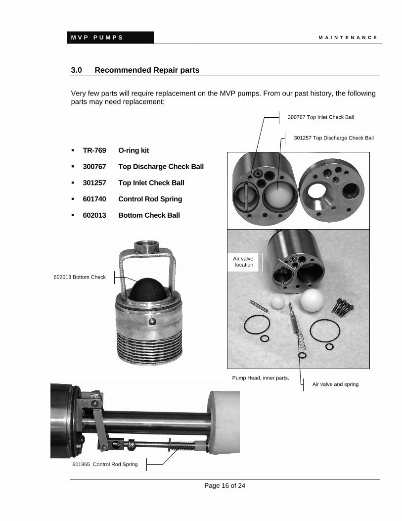
3.0 Recommended Repair parts
Very few parts will require replacement on the MVP pumps. From our past history, the following parts may need replacement:
TR-769 O-ring kit
300767 Top Discharge Check Ball
301257 Top Inlet Check Ball
601740 Control Rod Spring
602013 Bottom Check Ball
602013 Bottom Check
301257 Top Discharge Check Ball
300767 Top Inlet Check Ball
Air valve and spring
Air valve location
601955 Control Rod Spring
Pump Head, inner parts.

M V P P U M P S T R O U B L E S H O O T I N G
Page 17 of 24
TROUBLESHOOTING
Even the best installations can sometimes experience start-up problems. The following section provides some tips for troubleshooting potential problems.
1.0 Problem: Pump Not Operating
1.1 Is proper air pressure applied to the pump? Be sure all lines are connected to the clincher and pump correctly. Check for crimped lines from clincher to pump.
1.2 Is discharge line restricted? Check fluid level in the well Check upper intake on top loading pump. Is it clogged or sticking? Check for sticking float (clean stainless steel tubes inside of pump)
2.0 Problem: Pump blowing air into fluid discharge line momentarily at end of pump cycle.
Lower operating pressure of the pump.
3.0 Problem: Air coming from exhaust line continuously. Pump not operating.
Check to be sure air valve is sealing properly. Clean air valve as described in Maintenance section, paragraph 2.0.
4.0 Problem: Pump blowing air into discharge line continuously.
Check that the air valve is seating properly Check for sticking float (clean stainless steel tubes inside of pump)
5.0 Problem: Air blowing up the well continuously.
Upper intake valve may not be closing on the pump (foreign object in upper intake). Check for loose or broken air line above the pump.

M V P P U M P S T R O U B L E S H O O T I N G
Page 18 of 24
6.0 Returning Equipment for Service
IMPORTANT: Only pumps that are certified as uncontaminated will be accepted for warranty return or servicing. Durham Geo Slope Indicator or its agent must receive this certification prior to receiving the pump. If not, delivery of the pump will be refused and all costs incurred in returning the product to the customer will be paid by the customer. 6.1 Call DGSI to obtain a Returned Goods Authorization (RGA) number. 6.2 Clean all equipment. If the equipment is not cleaned, the customer will be charged for this
process and the proper disposal of material. 6.3 Properly package the equipment and apply the RGA number to the outside of the shipping
container. 6.4 Include any additional information about the equipment and service you require. 6.5 You will be contacted with an estimate prior to any repair being completed on the equipment.

M V P P U M P S A P P E N D I X A
Page 19 of 24
LIMITED WARRANTY
Durham Geo-Enterprises, Inc. / Slope Indicator (“DGSI”) warrants the products manufactured by DGSI to be free of defects of workmanship and material on a product basis. The products accompanied by this Warranty Statement are warranted for a period of ONE (1) YEAR from the date of delivery to the customer. If the customer is an authorized distributor of DGSI’s products, the warranty shall be for a period of ONE (1) YEAR from the date of delivery to the authorized distributor’s customer. The obligation of DGSI is hereafter limited to replacement or, at its option, repair of products returned to it, should DGSI's examination disclose, to its satisfaction, that the products were not free from defects. Products repaired or serviced by DGSI are warranted against defects in workmanship and materials for a period of 90 days, or the remainder of the original warranty period, whichever is greater. IN NO EVENT SHALL DGSI BE LIABLE FOR CONSEQUENTIAL OR SPECIAL DAMAGES, OR FOR INSTALLATION, ADJUSTMENT, LOST PROFITS OR OTHER COSTS WHICH MAY ARISE IN CONNECTION WITH SUCH PRODUCTS. THE APPLICABLE PRODUCT WARRANTY EXTENDS ONLY TO THE ORIGINAL CUSTOMER OF DGSI OR ITS AUTHORIZED DISTRIBUTOR, AS THE CASE MAY BE, AND IS EXPRESSLY IN LIEU OF ALL OTHER WARRANTIES, EXPRESS OR IMPLIED, WHETHER OF MERCHANTABILITY OR FITNESS FOR ANY PARTICULAR PURPOSE OR USE, AND OF ALL OTHER OBLIGATIONS AND LIABILITIES OF ANY KIND AND CHARACTER. EXCEPT FOR THE WARRANTY APPLICABLE TO THE SPECIFIC PRODUCT(S) PURCHASED, DGSI MAKES NO WARRANTY OF MERCHANTABILITY OF THE GOODS OR OF THE FITNESS OF THE GOODS FOR ANY PURPOSE. THERE ARE NO WARRANTIES WHICH EXTEND BEYOND THE DESCRIPTION ON THE FACE HEREOF. Any products, components or accessories that are not manufactured by DGSI and are supplied by other manufacturers are subject to their respective warranties. Certain products will carry their own warranties. For further assistance:
Call 1-800-837-0864 (toll free) or +1 (770) 465-7557 e-mail [email protected]

M V P P U M P S A P P E N D I X A
Page 20 of 24
APPENDIX A
1.0 Air Consumption TABLE A-1
OPERATING AIR PRESSURE COMPRESSED AIR CONSUMPTION RATE psi kPa (ft3/gal pumped) m3/gal pumped 60 414 .75 .021
70 483 .80 .022
80 552 .85 .024
90 620 .87 .025
100 690 .90 .026 AIR CONSUMPTION [ft3/min] = Total Pumping Rate [gal/min] x Air Consumption per gal pumped
[(ft3) at operating pressure*]
AIR CONSUMPTION [m3/min] = Total Pumping Rate [L/min] x Air consumption per gal pumped
[(m3) at operating pressure *]
* The operating air pressure will depend on the amount of force the MVP IV/MVP will need to push the water from the pump to the remediation equipment on the surface (total dynamic head). For example, at an operating pressure of 60 psi (413 kPa), the MVP IV/MVP will consume 0.75 ft3 of air/gal pumped. At an operating pressure of 100 psi (689 kPa), the pump will consume 0.90 ft3 of air/gal pumped. The total water recovery rate will dictate how often the pump cycles.
If you have any questions about sizing compressors, number of pumps required for your site, etc., please call DGSI technical service staff in Stone Mountain. They can be reached at [email protected] or 1-800-837-0864

M V P P U M P S A P P E N D I X B
Page 21 of 24
APPENDIX B
1.0 General MVP Specifications Pump Dimensions —3.5 in OD Operating Pressure — 10 psi minimum (6.9 kPa) to 100 psi maximum (689 kPa) Operating Temperature — 200°F maximum (49°C) Air Requirements — none. Suggested: 5-micron filtered, dry air [dew point 0°F (-17°C)] Pumping Volume —
Pump Body Length Gallons/cycle* 36 in Long Body 0.31 to 0.38 31 in Long Body 0.11 to 0.18
* Depends on air pressure and total dynamic head (TDH) Maximum Operating Depth — 225 ft (68 m) Materials — T303 stainless, with Nylon® intake and discharge check balls, Delrin® or Buna-N® bottom inlet check ball, epoxy float, Viton® O-rings.

M V P P U M P S A P P E N D I X C
Page 22 of 24
APPENDIX C
1.0 Air Purge Line
The use of the Air Purge Line during initial installation is highly recommended when pumping depths exceed 75 feet and in all landfill leachate-pumping applications. The Air Purge Line allows the field maintenance personal to cycle the pump manually independently of the internal float and valving. To cycle the pump manually, the exhaust and air inlet lines must be closed. The supply air supply would be connected to the Air Purge Line through an on-off valve. When the air supply is turned on, the compressed air will push the fluids through the pump to the surface. The fluid discharge line will shake when all the fluids have discharged from the pump and hoses. When this has occurred, the air can be shut off and the air line disconnected in order to allow the pump to refill. The pump can be cycled manually to: lighten the pump for ease of removal from deep wells, raise the pump above the liquid level , and manually cycle the pump to remove all fluids from the pump and hoses.
When the pump will not cycle automatically, manually cycling the pump may displace debris that was jamming the pump's mechanical components or bring fluids to the surface which may help identify the in-well problems (such as a well silting in or foaming agents being present) and to expel landfill gases that have entered the intake valving.
1.1 Remove the 1/8” plug head from port “C” on the pump
(indicated by the arrow on the photo on the right) and insert the 1/8 Male NPT x ¼ OD push-in tube fitting provided. Insert the ¼” air supply line and run it to the underside of the well clincher.
The arrow indicates the plug head to be removed

M V P P U M P S A P P E N D I X C
Page 23 of 24
1.2 On the top of the well clincher, remove the plastic plug (as indicated on the photo) and insert it in the air input port. Connect the three-way valve and On/Off valve as shown below. Depressing the button on the three-way valve will send compressed air to the pump and activate it.
Optional Kit TR-77050
Fitting goes on the pump (purge port). See item 1 on photo p 9.

M V P P U M P S A P P E N D I X D
Page 24 of 24
APPENDIX D
1.0 Decontamination Certificate
If you do not have your own decontamination certificate, feel free to use this simple form and enclose it with your return:
RGA #: ___________ Model: ____________ Serial Numner(s): _______________________
_____________________________________
_____________________________________
The undersigned certifies the all the equipment being returned under this Returned Goods Authorization (RGA) has been properly decontaminated by washing and brushing with Alconox® (or equivalent) to remove large particles, followed by rinsing with tap water. This equipment has been disassembled for complete decontamination.
Name (Print): ________________________ Company: ________________________________
Signature: ___________________________ Street: ___________________________________
Title: _____________ Date: __________ City: ______________, State: ____ Zip: ________
Durham Geo Slope Indicator reserves the right to refuse any equipment based on contamination or lack of decontamination.