Groundsmaster 3280-D2and 4-WheelDriveTractionUnits · FormNo. 3382-625RevA...
56
Form No. 3382-625 Rev A Groundsmaster ® 3280-D 2 and 4-Wheel Drive Traction Units Model No. 30344—Serial No. 314000001 and Up Model No. 30345—Serial No. 314000001 and Up Register at www.Toro.com. Original Instructions (EN) *3382-625* A
Transcript of Groundsmaster 3280-D2and 4-WheelDriveTractionUnits · FormNo. 3382-625RevA...

Form No. 3382-625 Rev A
Groundsmaster® 3280-D 2 and4-Wheel Drive Traction UnitsModel No. 30344—Serial No. 314000001 and Up
Model No. 30345—Serial No. 314000001 and Up
Register at www.Toro.com.Original Instructions (EN) *3382-625* A

This product complies with all relevant European directives,for details please see the separate product specific Declarationof Conformity (DOC) sheet.
WARNING
CALIFORNIAProposition 65 Warning
This product contains a chemical or chemicalsknown to the State of California to cause cancer,
birth defects, or reproductive harm.
Diesel engine exhaust and some of itsconstituents are known to the State ofCalifornia to cause cancer, birth defects,
and other reproductive harm.
This spark ignition system complies with Canadian ICES-002.
Important: This engine is not equipped with a sparkarrester muffler. It is a violation of California PublicResource Code Section 4442 to use or operate the engineon any forest-covered, brush-covered, or grass-coveredland. Other states or federal areas may have similar laws.
IntroductionThis machine is a ride-on, rotary-blade lawnmower intendedto be used by professional, hired operators in commercialapplications. It is primarily designed for cutting grass onwell-maintained lawns in parks, golf courses, sports fields,and on commercial grounds. It is not designed for cuttingbrush, mowing grass and other growth alongside highways,or for agricultural uses.
Read this information carefully to learn how to operate andmaintain your product properly and to avoid injury andproduct damage. You are responsible for operating theproduct properly and safely.
You may contact Toro directly at www.Toro.com for productand accessory information, help finding a dealer, or to registeryour product.
Whenever you need service, genuine Toro parts, or additionalinformation, contact an Authorized Service Dealer or ToroCustomer Service and have the model and serial numbers ofyour product ready. Figure 1 identifies the location of themodel and serial numbers on the product. Write the numbersin the space provided.
Figure 1
1. Model and serial number location
Model No.
Serial No.
This manual identifies potential hazards and has safetymessages identified by the safety alert symbol (Figure 2),which signals a hazard that may cause serious injury or deathif you do not follow the recommended precautions.
Figure 2
1. Safety alert symbol.
This manual uses two other words to highlight information.Important calls attention to special mechanical informationand Note emphasizes general information worthy of specialattention.
© 2013—The Toro® Company8111 Lyndale Avenue SouthBloomington, MN 55420 2
Contact us at www.Toro.com.Printed in the USA.All Rights Reserved
ContentsIntroduction .................................................................. 2Safety ........................................................................... 4
Safe Operating Practices........................................... 4Toro Riding Mower Safety ........................................ 6Sound Power Level .................................................. 7Sound Pressure Level ............................................... 7Vibration Level ...................................................... 7Safety and Instructional Decals ................................. 8
Setup ...........................................................................141 Installing the SteeringWheel..................................152 Installing the Hood Handle ...................................153 Installing the Seat.................................................164 Installing the Seat Belt ..........................................165 Installing the Manual Tube ....................................166 Adjusting the ROPS .............................................177 Activating and Charging the Battery ........................178 Checking the Tire Pressure ....................................199 Installing the Lift Lock Lever (For CEOnly) ................................................................19
10 Adjusting the Counterbalance Pressure..................2011 Installing Rear Weights........................................2112 Checking Fluid Levels .........................................2313 Reading the Manuals and Viewing the TrainingMaterials............................................................23
Product Overview .........................................................24Controls ...............................................................24Specifications ........................................................27Attachments/Accessories........................................27
Operation ....................................................................27Checking the Engine Oil Level .................................27Checking the Cooling System ..................................28Checking the Hydraulic System ................................28Adding Fuel...........................................................29Checking the Rear Axle Lubricant (Model 30345only) .................................................................30
Checking the Bidirectional Clutch Lubricant(Model 30345 only) .............................................31
Using the Rollover Protection System (ROPS) ............31Starting/Stopping the Engine ..................................32Bleeding the Fuel System.........................................32Checking the Interlock System .................................33Pushing or Towing theMachine................................33Standard Control Module (SCM) ..............................34Operating Tips ......................................................35
Maintenance .................................................................36RecommendedMaintenance Schedule(s) ......................36Daily Maintenance Checklist ....................................37
Lubrication ...............................................................38Greasing the Bearings and Bushings ..........................38
Engine Maintenance ..................................................41General Air Cleaner Maintenance .............................41Changing the Engine Oil And Filter ..........................42
Fuel SystemMaintenance ...........................................42Servicing theWater Separator ..................................42Cleaning the Fuel Tank............................................42Fuel Lines and Connections .....................................43
Bleeding Air from the Injectors ................................43Electrical SystemMaintenance ....................................43Servicing the Battery...............................................43Storing the Battery..................................................44Servicing theWiring Harness ...................................44Accessing the Fuses ................................................44
Drive SystemMaintenance .........................................45Changing the Rear Axle Lubricant (Model 30345only) .................................................................45
Checking Steering Cylinder Bolt Torque (Model30345 only) ........................................................45
Changing the Bidirectional Clutch Lubricant(Model 30345 only) .............................................45
Adjusting the TractionDrive for Neutral....................45Adjusting Rear Wheel Toe-in....................................46Adjusting Steering Stops (Model 30345only) .................................................................47
Cooling SystemMaintenance ......................................48Cleaning the Radiator and the Screen.........................48
Brake Maintenance ....................................................48Adjusting the Parking Brake Interlock Switch..............48Adjusting the Service Brakes ....................................49
Belt Maintenance ......................................................50Checking the Alternator Belt ...................................50Servicing the PTO Belt............................................50
Controls SystemMaintenance .....................................51Adjusting the PTO Clutch .......................................51Adjusting the Traction Pedal ....................................51Adjusting the Tilt Steering Control............................52
Hydraulic SystemMaintenance ....................................52Changing the Hydraulic Oil And Filter.......................52
Storage ........................................................................53Machine ................................................................53Engine ..................................................................53
3
SafetyThis machine meets or exceeds CEN standard EN 836:1997,ISO standard 5395:1990 (when appropriate decals applied),and ANSI B71.4-2004 specifications in effect at the time ofproduction when equipped with rear weight as listed in theimplement Operator's Manual.
Improper use or maintenance by the operator or owner canresult in injury. To reduce the potential for injury, complywith these safety instructions and always pay attention to thesafety alert symbol, which means CAUTION, WARNING, orDANGER—“personal safety instruction.” Failure to complywith the instruction may result in personal injury or death.
Safe Operating PracticesThe following instructions are adapted from the CENstandard EN 836:1997, ISO standard 5395:1990, and ANSIB71.4-2012.
Training• Read the Operator's Manual and other training material
carefully. If the operator or mechanic can not read thelanguage of this manual it is the owner's responsibility toexplain this material to them.
• Be familiar with the controls, safety signs, and the properuse of the equipment.
• Never allow children or people unfamiliar with theseinstructions to use or service the mower. Localregulations may restrict the age of the operator.
• Never mow while people, especially children, or pets arenearby.
• Keep in mind that the operator or user is responsible foraccidents or hazards occurring to other people or theirproperty.
• Do not carry passengers.
• All operators and mechanics should seek and obtainprofessional and practical instruction. The owner isresponsible for training the users. Such instruction shouldemphasize:
– the need for care and concentration when workingwith ride-on machines;
– control of a ride-on machine sliding on a slope willnot be regained by the application of the brake. Themain reasons for loss of control are:
◊ insufficient wheel grip;
◊ being driven too fast;
◊ inadequate braking;
◊ the type of machine is unsuitable for its task;
◊ lack of awareness of the effect of groundconditions, especially slopes;
◊ incorrect hitching and load distribution.• The owner/user can prevent and is responsible for
accidents or injuries occurring to himself or herself, otherpeople, or property.
Preparation• While mowing, always wear substantial footwear, long
trousers, hard hat, safety glasses, and hearing protection.Long hair, loose clothing, or jewelry may get tangledin moving parts. Do not operate the equipment whenbarefoot or wearing open sandals.
• Thoroughly inspect the area where the equipment is tobe used and remove all objects which may be thrown bythe machine.
• Replace faulty silencers/mufflers.• Evaluate the terrain to determine what accessories and
attachments are needed to properly and safely performthe job. Only use accessories and attachments approvedby the manufacturer.
• Check the operator presence controls, safety switches andshields to make sure they are attached and functioningproperly. Do not operate unless they are functioningproperly.
CAUTIONAdequate rear weight is necessary to preventthe rear wheels from leaving the ground. Donot stop suddenly while deck or implement israised. Do not travel down hill with the deck orimplement raised. If the rear wheels leave theground, steering is lost.
Safe Handling of Fuels• To avoid personal injury or property damage, use
extreme care in handling gasoline. Gasoline is extremelyflammable and the vapors are explosive.
• Extinguish all cigarettes, cigars, pipes, and other sourcesof ignition.
• Use only an approved fuel container.• Never remove fuel cap or add fuel with the engine
running.• Allow engine to cool before refueling.• Never refuel the machine indoors.• Never store the machine or fuel container where there is
an open flame, spark, or pilot light such as on a waterheater or on other appliances.
• Never fill containers inside a vehicle or on a truck ortrailer bed with a plastic liner. Always place containers onthe ground away from your vehicle before filling.
• Remove equipment from the truck or trailer and refuel iton the ground. If this is not possible, then refuel suchequipment with a portable container, rather than from afuel dispenser nozzle.
4

• Keep the nozzle in contact with the rim of the fuel tankor container opening at all times until fueling is complete.Do not use a nozzle lock open device.
• If fuel is spilled on clothing, change clothing immediately.• Never overfill fuel tank. Replace fuel cap and tighten
securely.
Operation• Do not operate the engine in a confined space where
dangerous carbon monoxide fumes can collect.
WARNINGEngine exhaust contains carbon monoxide,which is an odorless, deadly poison that can killyou.
Do not run engine indoors or in an enclosedarea.
• Mow only in daylight or in good artificial light.• Before attempting to start the engine, disengage all blade
attachment clutches, shift into neutral, and engage theparking brake.
• Do not put hands or feet near or under rotating parts.Keep clear of the discharge opening at all times.
• Remember there is no such thing as a safe slope. Travelon grass slopes requires particular care. To guard againstoverturning:– do not stop or start suddenly when going up or
downhill;– machine speeds should be kept low on slopes and
during tight turns;– stay alert for humps and hollows and other hidden
hazards;– never mow across the face of the slope.
• Stay alert for holes in the terrain and other hidden hazards.• Watch out for traffic when crossing or near roadways.• Stop the blades rotating before crossing surfaces other
than grass.• Never direct the discharge of material toward bystanders
nor allow anyone near the machine while in operation.• Never operate the machine with damaged guards, shields,
or without safety protective devices in place. Be sure allinterlocks are attached, adjusted properly, and functioningproperly.
• Do not change the engine governor settings or over speedthe engine. Operating the engine at excessive speed mayincrease the hazard of personal injury.
• Before leaving the operator's position:– stop on level ground;– disengage the power take-off and lower the
attachments;– Set the parking brake;
– stop the engine and remove the key.• Disengage drive to attachments when transporting or not
in use.• Stop the engine and disengage drive to attachment
– before refuelling;– before removing the grass catcher/catchers;– before making height adjustment unless adjustment
can be made from the operator's position.– before clearing blockages;– before checking, cleaning or working on the mower;– after striking a foreign object or if an abnormal
vibration occurs. Inspect the mower for damageand make repairs before restarting and operating theequipment.
• Keep hands and feet away from the mower deck.• Look behind and down before backing up to be sure of
a clear path.• Slow down and use caution when making turns and
crossing roads and sidewalks. Disengage blades if notmowing.
• Be aware of the mower discharge direction and do notpoint it at anyone.
• Do not operate the mower under the influence of alcoholor drugs
• Lightning can cause severe injury or death. If lightningis seen or thunder is heard in the area, do not operatethe machine; seek shelter.
• Use care when loading or unloading the machine intoa trailer or truck
• Use care when approaching blind corners, shrubs, trees,or other objects that may obscure vision.
Rollover Protection System (ROPS) -Use and Maintenance• The ROPS is an integral and effective safety device. Keep
a folding ROPS in the raised and locked position and usethe seat belt when operating the machine.
• Lower a folding ROPS temporarily only when absolutelynecessary. Do not wear the seat belt when folded down
• Be aware there is no rollover protection when a foldedROPS is in the down position.
• Be certain that the seat belt can be released quickly inthe event of an emergency.
• Check the area to be mowed and never fold down afolding ROPS in areas where there are slopes, drop offsor water
• Check carefully for overhead clearances (i.e. branches,doorways, electrical wires) before driving under anyobjects and do not contact them
• Keep the ROPS in safe operating condition byperiodically thoroughly inspecting for damage andkeeping all mounting fasteners tight.
5
• Replace a damaged ROPS. Do not repair or revise.• Do not remove the ROPS.• Any alterations to a ROPS must be approved by the
manufacturer.
Maintenance and Storage• Keep all nuts, bolts and screws tight to be sure the
equipment is in safe working condition.• Never store the equipment with fuel in the tank inside a
building where fumes may reach an open flame or spark.• Allow the engine to cool before storing in any enclosure.• To reduce the fire hazard, keep the engine,
silencer/muffler, battery compartment and fuel storagearea free of grass, leaves, or excessive grease.
• Keep all parts in good working condition and all hardwareand hydraulic fittings tightened. Replace all worn ordamaged parts and decals
• If the fuel tank has to be drained, do this outdoors.• Be careful during adjustment of the machine to prevent
entrapment of the fingers between moving blades andfixed parts of the machine.
• On multi-spindle mowers, take care as rotating one bladecan cause other blades to rotate.
• Disengage drives, lower the deck, set parking brake, stopengine and remove the key from the ignition. Wait for allmovement to stop before adjusting, cleaning or repairing.
• Clean grass and debris from decks, drives,silencers/mufflers, engine and underside of machine tohelp prevent fires. Clean up oil or fuel spillage.
• Use jack stands to support components when required.• Carefully release pressure from components with stored
energy.• Disconnect battery before making any repairs. Disconnect
the negative terminal first and the positive last. Reconnectpositive first and negative last.
• Use care when checking the blades. Wear gloves and usecaution when servicing them. Only replace blades. Neverstraighten or weld them.
• Keep hands and feet away from moving parts. If possible,do not make adjustments with the engine running.
• Charge batteries in an open well ventilated area, awayfrom spark and flames. Unplug charger before connectingor disconnecting from battery. Wear protective clothingand use insulated tools.
Hauling• Use care when loading or unloading the machine into a
trailer or truck.• Use full width ramps for loading machine into trailer or
truck.• Tie the machine down securely using straps, chains, cable,
or ropes. Both front and rear straps should be directeddown and outward from the machine
Toro Riding Mower SafetyThe following list contains safety information specific to Toroproducts or other safety information that you must know thatis not included in the CEN, ISO, or ANSI standard.
This product is capable of amputating hands and feet andthrowing objects. Always follow all safety instructions toavoid serious injury or death.
Use of this product for purposes other than its intended usecould prove dangerous to user and bystanders.
• Know how to stop the engine quickly.
• Do not operate the machine while wearing tennis shoesor sneakers.
• Wearing safety shoes and long pants is advisable andrequired by some local ordinances and insuranceregulations.
• Handle fuel carefully. Wipe up any spills.
• Check the safety interlock switches daily for properoperation. If a switch should fail, replace the switchbefore operating the machine.
• Before starting the engine, sit on the seat.
• Using the machine demands attention. To prevent lossof control:
– Do not drive close to sand traps, ditches, creeks, orother hazards.
– Reduce speed when making sharp turns. Avoidsudden stops and starts.
– This machine is not designed or equipped for on-roaduse and is a “slow-moving vehicle.” If you must crossor travel on a public road, you should be aware of andcomply with local regulations, such as required lights,slow moving vehicle signs, and reflectors.
– When near or crossing roads, always yield theright-of-way.
– Apply the service brakes when going downhill tokeep forward speed slow and to maintain control ofthe machine.
• Raise the deck when driving from one work area toanother.
• Do not touch the engine, silencer/muffler, or exhaustpipe while the engine is running or soon after it hasstopped because these areas could be hot enough to causeburns.
• If the engine stalls or machine cannot make it to the topof a slope, do not turn the machine around. Always backslowly, straight down the slope.
• When a person or pet appears unexpectedly in or near themowing area, stop mowing. Careless operation, combinedwith terrain angles, ricochets, or improperly positionedguards can lead to thrown object injuries. Do not resumemowing until the area is cleared.
6

Maintenance and Storage• Make sure all hydraulic line connectors are tight and all
hydraulic hoses and lines are in good condition beforeapplying pressure to the system.
• Keep your body and hands away from pin hole leaks ornozzles that eject hydraulic fluid under high pressure.Use paper or cardboard, not your hands, to search forleaks. Hydraulic fluid escaping under pressure can havesufficient force to penetrate the skin and cause seriousinjury. Seek immediate medical attention if fluid isinjected into skin.
• Before disconnecting or performing any work on thehydraulic system, all pressure in the system must berelieved by stopping the engine and lowering the deck andattachments to the ground.
• Check all fuel lines for tightness and wear on a regularbasis. Tighten or repair them as needed.
• If the engine must be running to perform a maintenanceadjustment, keep hands, feet, clothing, and any partsof the body away from the deck, attachments, and anymoving parts, especially the screen at the side of theengine. Keep everyone away.
• If major repairs are ever needed or if assistance is desired,contact an Authorized Toro Distributor.
• Use only Toro approved attachments and replacementparts. The warranty may be voided if used withunapproved attachments.
Sound Power LevelThis unit has a guaranteed sound power level of 105 dBA,which includes an Uncertainty Value (K) of 1 dBA.
Sound power level was determined according to theprocedures outlined in ISO 11094.
Sound Pressure LevelThis unit has a sound pressure level at the operator’s ear of 90dBA, which includes an Uncertainty Value (K) of 1 dBA.
Sound pressure level was determined according to theprocedures outlined in EN 836.
Vibration LevelHand-Arm
Measured vibration level for right hand = 1.25 m/s2
Measured vibration level for left hand = 1.28 m/s2
Uncertainty Value (K) = 0.5 m/s2
Measured values were determined according to the proceduresoutlined in EN 836.
Whole Body
Measured vibration level = 0.37 m/s2
Uncertainty Value (K) = 0.5 m/s2
Measured values were determined according to the proceduresoutlined in EN 836.
7

Safety and InstructionalDecals
Safety decals and instructions are easily visible to the operator and are located near any area of potentialdanger. Replace any decal that is damaged or lost.
106-9206
1. Wheel torque specifications2. Read the Operator's Manual.
106-6754
1. Warning—do not touch the hot surface.2. Cutting/dismemberment hazard, fan and entanglement
hazard, belt—stay away from moving parts.
106-5976
1. Engine coolant underpressure
3. Warning—do not touch thehot surface.
2. Explosion hazard—readthe Operator's Manual.
4. Warning—read theOperator's Manual.
93-7841
1. Warning—read the Operator's Manual.
93-6680
93-7272
1. Cutting/dismemberment hazard; fan—stay away frommoving parts.
93-6697(Model 30345)
1. Read the Operator'sManual.
2. Add SAE 80w-90 (APIGL-5) oil every 50 hours.
93-6686
1. Hydraulic oil2. Read the Operator's Manual.
105-2511
1. Read Operator's Manual for starting instructions.
8
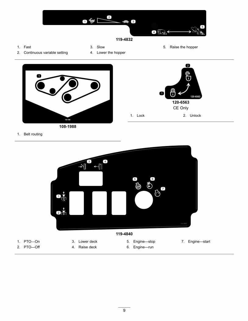
119-4832
1. Fast 3. Slow 5. Raise the hopper2. Continuous variable setting 4. Lower the hopper
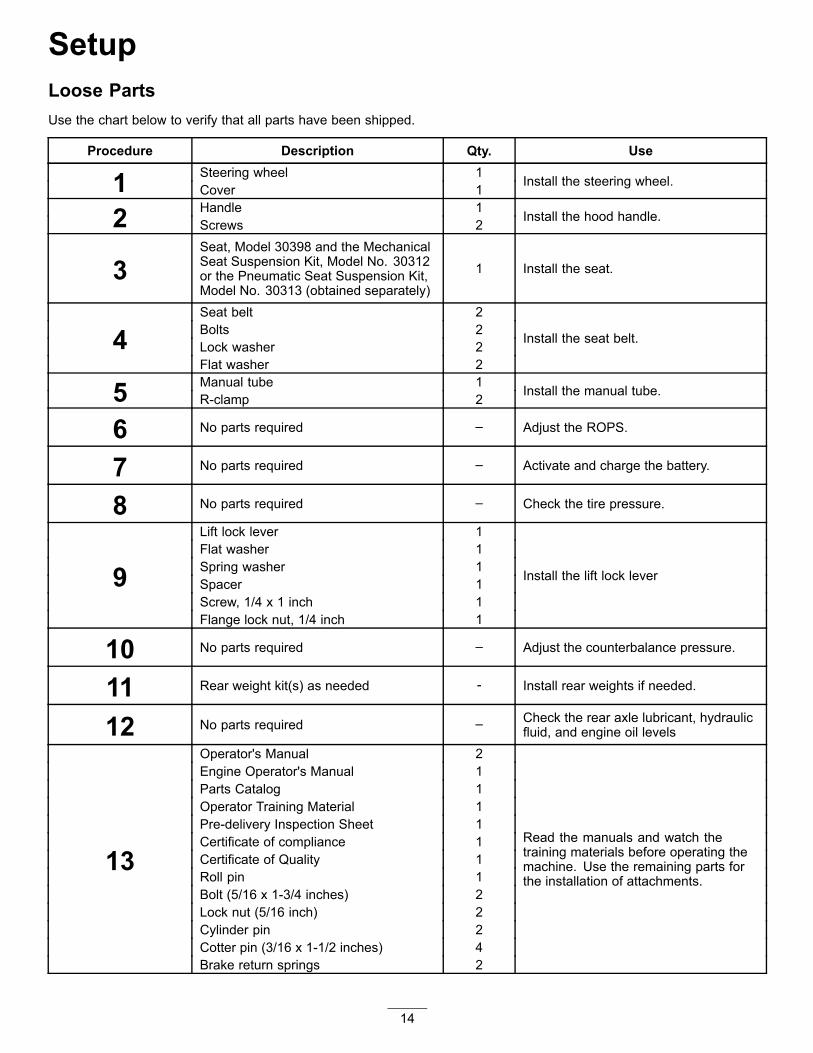
108-1988
1. Belt routing
120-6563CE Only
1. Lock 2. Unlock
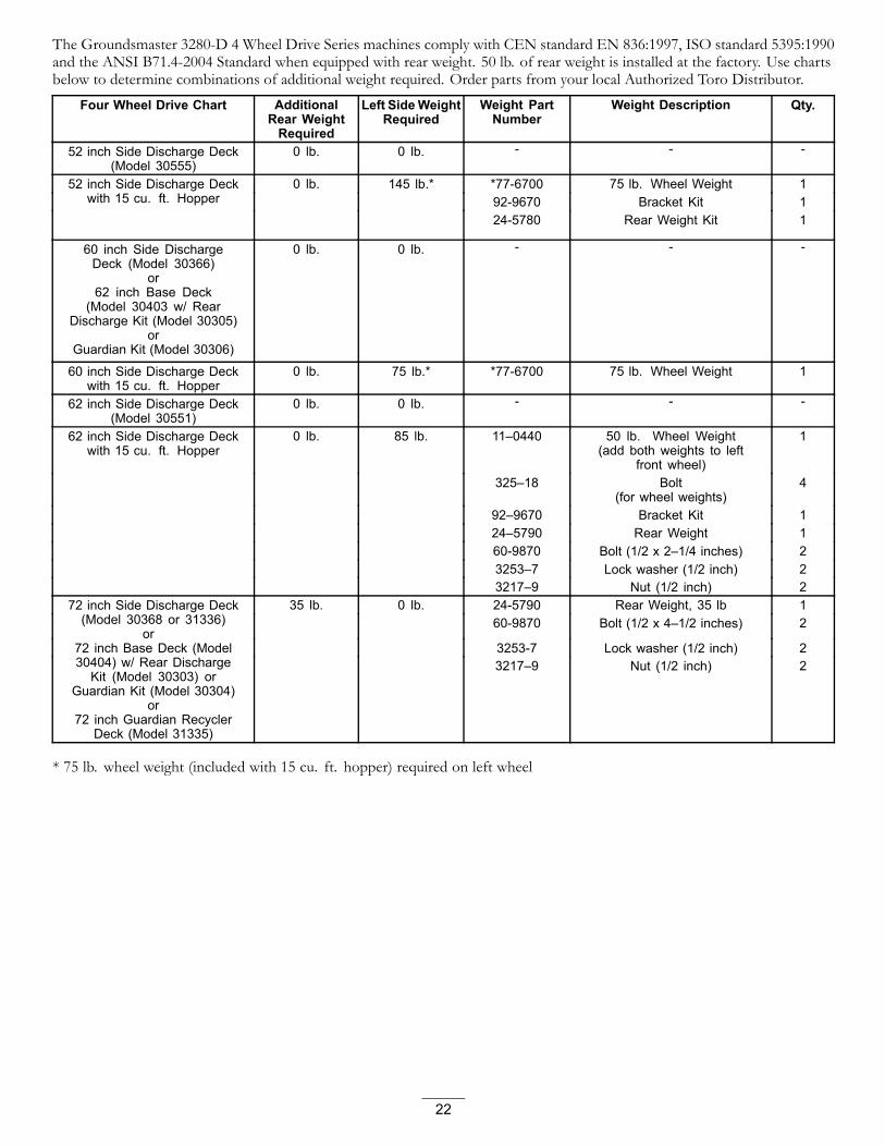
119-4840
1. PTO—On 3. Lower deck 5. Engine—stop 7. Engine—start2. PTO—Off 4. Raise deck 6. Engine—run
9

115-3027
114-2855
1. Warning—read the Operator's Manual,all operators should be trained beforeoperating the machine.
3. Cutting/dismemberment hazard ofhands or feet, mower blade—stayaway from moving parts.
5. Tipping hazard—when driving downslopes, lower the cutting unit, slowmachine before turning, do not turnat high speeds, and if the roll bar isinstalled, wear the seat belt.
2. Thrown object hazard—keepbystanders a safe distance from themachine and keep the deflector inplace.
4. Warning—engage the parking brake,and remove the ignition key beforeleaving the machine.
10

108-6585(Apply over 114–2855 for CE)
* This safety decal includes a slope warning required on the machine for compliance to the European Lawn Mower Safety Standard EN836:1997. The conservative maximumslope angles indicated for operation of this machine are prescribed by and required by this standard.
1. Warning—read the Operator's Manual,all operators should be trained beforeoperating the machine.
3. Cutting/dismemberment hazard ofhands or feet, mower blade—stayaway from moving parts.
5. Tipping hazard—do not drive themachine on a slope greater than 10degrees; when driving down slopes,lower the cutting unit, and if the roll baris raised, wear the seat belt.
2. Thrown object hazard—keepbystanders a safe distance from themachine and keep the deflector inplace.
4. Warning—engage the parking brake,and remove the ignition key beforeleaving the machine.
106-9290
1. Inputs 5. In seat 9. Outputs 13. Start2. Not active 6. Power Take-off (PTO) 10. Power Take Off (PTO) 14. Power3. High temperature shutdown 7. Parking brake Off 11. Start4. High temperature warning 8. Neutral 12. Energize to Run (ETR)
11

108-2073
1. Warning—there is no rollover protection when the roll bar isdown.
2. To avoid injury or death from a rollover accident, keep theroll bar in the raised and locked position and wear the seatbelt. Lower the roll bar only when absolutely necessary; donot wear the seat belt when the roll bar is down.
3. Read the Operator's Manual; drive slowly and carefully.
105-7179
1. Read Operator's Manual. 2. Parking brake
93-7834
1. No step 4. Traction-reverse2. Traction pedal 5. Warning—shut off PTO
prior to raising decks; donot operate decks whenthey are in raised position
3. Traction-forward
82-8940
1. Locked 3. Unlocked2. Tilt steering
12

Battery SymbolsSome or all of these symbols are on your battery.
1. Explosion hazard 6. Keep bystanders a safedistance from the battery.
2. No fire, open flames, orsmoking.
7. Wear eye protection;explosive gases cancause blindness and otherinjuries.
3. Caustic liquid/chemicalburn hazard
8. Battery acid can causeblindness or severe burns.
4. Wear eye protection. 9. Flush eyes immediatelywith water and get medicalhelp fast.
5. Read the Operator’sManual.
10. Contains lead; do notdiscard.
Manufacturer's Mark
1. Indicates the blade is identified as a part from the originalmachine manufacturer.
13
SetupLoose PartsUse the chart below to verify that all parts have been shipped.
Procedure Description Qty. UseSteering wheel 11 Cover 1 Install the steering wheel.
Handle 12 Screws 2 Install the hood handle.
3Seat, Model 30398 and the MechanicalSeat Suspension Kit, Model No. 30312or the Pneumatic Seat Suspension Kit,Model No. 30313 (obtained separately)
1 Install the seat.
Seat belt 2Bolts 2Lock washer 24Flat washer 2
Install the seat belt.
Manual tube 15 R-clamp 2 Install the manual tube.
6 No parts required – Adjust the ROPS.
7 No parts required – Activate and charge the battery.
8 No parts required – Check the tire pressure.
Lift lock lever 1Flat washer 1Spring washer 1Spacer 1Screw, 1/4 x 1 inch 1
9Flange lock nut, 1/4 inch 1
Install the lift lock lever
10 No parts required – Adjust the counterbalance pressure.
11 Rear weight kit(s) as needed - Install rear weights if needed.
12 No parts required – Check the rear axle lubricant, hydraulicfluid, and engine oil levels
Operator's Manual 2Engine Operator's Manual 1Parts Catalog 1Operator Training Material 1Pre-delivery Inspection Sheet 1Certificate of compliance 1Certificate of Quality 1Roll pin 1Bolt (5/16 x 1-3/4 inches) 2Lock nut (5/16 inch) 2Cylinder pin 2Cotter pin (3/16 x 1-1/2 inches) 4
13
Brake return springs 2
Read the manuals and watch thetraining materials before operating themachine. Use the remaining parts forthe installation of attachments.
14

Note: Determine the left and right sides of the machinefrom the normal operating position.
WARNINGThe PTO universal shaft is attached to the machineframe. Do not engage the PTO without firstremoving the universal shaft or coupling it to asuitable implement.
1Installing the Steering Wheel
Parts needed for this procedure:1 Steering wheel
1 Cover
Procedure1. Remove the steering wheel from the shipping skid.
Figure 3
1. Steering wheel 4. Foam collar2. Jam nut 5. Cover3. Dust cover 6. Washer
2. Remove the jam nut and washer from the steeringshaft. Ensure that the foam collar and dust coverremain on the steering shaft (Figure 3).
3. Slide the steering wheel and washer onto the steeringshaft (Figure 3).
4. Secure the steering wheel to the shaft with the jam nut.Tighten the jam nut to 27-35 N-m (20-26 ft-lb).
5. Mount the cover to the steering wheel (Figure 3).
2Installing the Hood Handle
Parts needed for this procedure:1 Handle
2 Screws
Procedure1. Remove and discard the 2 screws and nuts securing the
hood cable bracket and to the underside of the hood(Figure 4).
Figure 4
1. Hood cable bracket
2. Mount the handle and the cable bracket to the hoodwith 2 screws (Figure 5).
15

Figure 5
1. Handle 2. Hood cable bracket
3Installing the Seat
Parts needed for this procedure:
1Seat, Model 30398 and the Mechanical SeatSuspension Kit, Model No. 30312 or the PneumaticSeat Suspension Kit, Model No. 30313 (obtainedseparately)
ProcedureThe Groundsmaster 3280-D is shipped without the seatassembly. The optional Seat, Model 30398 and the MechanicalSeat Suspension Kit, Model No. 30312 or the Pneumatic SeatSuspension Kit, Model No. 30313 must be obtained andinstalled. Refer to the seat kit for the installation instructions.
Note: An Auxiliary Power Unit Kit, Model No. 30382,must be obtained and installed before installing a PneumaticSuspension Seat Kit to the machine.
Note: Refer to Installing the Manual Tube before the seat ismounted to the seat suspension.
4Installing the Seat BeltParts needed for this procedure:
2 Seat belt
2 Bolts
2 Lock washer
2 Flat washer
ProcedureInstall each end of the seat belt in the holes in the back of theseat with 2 bolts (7/16 x 1 inch), flat washers (7/16 inch),and lock washers (7/16 inch) (Figure 6).
Important: Mount the latch side of the belt to the rightside of the seat.
Figure 6
1. Seat belt latch
5Installing the Manual TubeParts needed for this procedure:
1 Manual tube
2 R-clamp
Procedure1. Remove the manual tube and R-clamps secured to
the seat plate. Discard the 2 mounting bolts and flatwashers.
2. Remove the 2 nuts and vinyl caps (if previouslyinstalled) securing the upper seat bracket to the left sideof the seat suspension (Figure 7).
16

3. Loosely mount the R-clamps to the seat bracketstuds with the 2 nuts previously removed. (Figure7). The R-clamps are to be positioned under the seatsuspension tabs.
Figure 7
1. R-clamps 4. Manual tube2. Upper seat bracket 5. Vinyl cap3. Seat suspension
4. Install the manual tube into the R-clamps and tightenthe nuts (Figure 7).
5. Insert the vinyl caps onto the seat bracket studs.
6Adjusting the ROPS
No Parts Required
Procedure1. Remove the hairpin cotter pins and remove the two
pins from the roll bar (Figure 8).
Figure 8
1. Roll bar 3. Hairpin cotter pin2. Pin
2. Raise the roll bar to the upright position and installthe two pins and secure them with the hairpin cotterpins (Figure 8).
Note: The roll bar is an integral and effective safetydevice. Keep the roll bar in the raised and lockedposition. Lower the roll bar temporarily only whenabsolutely necessary.
7Activating and Charging theBattery
No Parts Required
ProcedureUse only electrolyte (1.265 Specific Gravity) to fill batteryinitially.
1. Remove the battery from the machine.
Important: Do not add electrolyte while thebattery is in the machine. You could spill it,causing corrosion.
2. Clean the top of the battery and remove the vent caps(Figure 9).
17

Figure 9
1. Vent caps
3. Carefully fill each cell with electrolyte until the platesare covered with about 6 mm (1/4 inch) of fluid(Figure 10).
Figure 10
1. Electrolyte
4. Allow approximately 20 to 30 minutes for theelectrolyte to soak into the plates. Refill as necessary tobring the electrolyte to within about 6 mm (1/4 inch)of the bottom of the fill well (Figure 10).
WARNINGCharging the battery produces gasses that canexplode.
Never smoke near the battery and keep sparksand flames away from battery.
5. Connect a 3 to 4 amp battery charger to the batteryposts. Charge the battery at a rate of 3 to 4 ampsuntil the specific gravity is 1.250 or higher and thetemperature is at least 16° C (60° F) with all cellsgassing freely.
6. When the battery is charged, disconnect the chargerfrom the electrical outlet and battery posts.
Note: Incomplete charging may result in gassing ofthe battery and the over flow of battery acid causingcorrosive damage to the machine.
WARNINGCALIFORNIA
Proposition 65 WarningBattery posts, terminals, and related
accessories contain lead and lead compounds,chemicals known to the State of Californiato cause cancer and reproductive harm.
Wash hands after handling.
WARNINGBattery terminals or metal tools could shortagainst metal tractor components causingsparks. Sparks can cause the battery gasses toexplode, resulting in personal injury.
• When removing or installing the battery,do not allow the battery terminals to touchany metal parts of the tractor.
• Do not allow metal tools to short betweenthe battery terminals and metal parts ofthe tractor.
7. Install the battery into the machine.
8. First, install the positive cable (red) to the positive (+)terminal and then the negative cable (black) to thenegative (-) terminal of the battery (Figure 11). Slidethe rubber boot over the positive terminal to prevent apossible short from occurring.
WARNINGIncorrect battery cable routing could damagethe machine and cables causing sparks.Sparks can cause the battery gasses toexplode, resulting in personal injury.
• Always disconnect the negative (black)battery cable before disconnecting thepositive (red) cable.
• Always connect the positive (red) batterycable before connecting the negative(black) cable.
18

Figure 11
1. Positive (+) 2. Negative (-)
WARNINGConnecting cables to the wrong post coulddamage the electrical system and result inpersonal injury.
Note: Ensure that the battery cables are routed awayfrom any sharp edges or moving parts.
8Checking the Tire Pressure
No Parts Required
ProcedureThe tires are over inflated for shipping. Therefore, releasesome of the air to reduce the pressure. Correct air pressure infront and rear tires is 138 kpa (20 psi).
9Installing the Lift Lock Lever(For CE Only)
Parts needed for this procedure:1 Lift lock lever
1 Flat washer
1 Spring washer
1 Spacer
1 Screw, 1/4 x 1 inch
1 Flange lock nut, 1/4 inch
Procedure1. Carefully locate and puncture the control panel decal
material, in front of the lift switch, to expose themounting hole for the lift lock lever (Figure 12).
Figure 12
1. Mounting screw (4) 3. Mounting hole location2. Control panel
2. Remove the (4) screws securing the control panel tothe machine (Figure 12).
3. Insert the lift lock lever, spacer, wave washer andflat washer onto the 1/4 x 1 inch pan head screwpositioning as shown in Figure 13.
19

Figure 13
1. Screw 5. Flat washer2. Lift lock lever 6. Decal3. Spring washer 7. Lock nut4. Spacer
4. Insert the lift lock lever assembly screw into the controlpanel hole and secure it with a lock nut. Position thelift lock lever as shown in Figure 13.
5. Affix the lift lock lever decal to the control panel,positioning as shown inFigure 13.
6. Secure the control panel to machine with the screwspreviously removed.
7. To operate the lift lock lever, rotate it under the frontedge of the lift switch to prevent the switch from beingactivated.
10Adjusting the CounterbalancePressureNo Parts Required
ProcedureFor best performance, the cutting unit bounce on uneventurf is minimal and it does not ride heavily over flat terrain.If scalping occurs or the cut is uneven from side to side,there may be too much weight on the deck and the weightmay have to be transferred to the machine: i.e. increasedcounterbalance pressure.
By contrast, if too much weight is transferred to the machine,the deck will bounce excessively and the cut will be uneven.If the cutting unit does not perform properly, adjust thecounterbalance pressure as follows:
1. Ensure that the parking brake is set, the PTO switch isin the Off position, and the cutting unit is lowered.
2. Locate the lift manifold on the right side of themachine.
3. Connect a pressure gauge to the test port at the rear ofthe lift manifold (Figure 14).
Figure 14
1. Counterbalance spool 2. Test port
4. On the front of the lift manifold, remove the cap fromthe manifold counterbalance spool (Figure 14).
5. Loosen the jam nut at the bottom of the counterbalancespool (Figure 14).
6. Start the engine and set the throttle to high idle.
7. Using an Allen wrench, adjust the lift valve spool untilthe desired pressure is attained on the gauge. See thechart below for the recommended pressure setting forthe cutting deck.
Cutting Deck Counterbalance Pressure
52 inch Side Discharge Deck(Model 30555)
448 kpa (65 psi)
60 inch Side Discharge Deck(Model 30366) or 62 in BaseDeck (Model 30403) or 62 inSide Discharge Deck (Model30551)
1206 kpa (175 psi)
72 inch Side Discharge Deck(Model 31336) or 72 in BaseDeck (Model 30404) or 72in Guardian Recycler Deck(Model 31335)
1516 kpa (220 psi)
8. Stop the engine.
9. Tighten the jam nut on the bottom of thecounterbalance spool. Torque the nut to 13-16 N-m(10-12 ft.-lb).
10. Remove the pressure gauge from the test port.
20

11Installing Rear Weights
Parts needed for this procedure:- Rear weight kit(s) as needed
ProcedureThe Groundsmaster 3280-D Two Wheel Drive Series machines comply with CEN standard EN 836:1997, ISO standard5395:1990 and the ANSI B71.4-2004 Standard when equipped with rear weight. 215 lb. of rear weight is installed at the factory.Use charts below to determine combinations of additional weight required. Order parts from your local Authorized ToroDistributor.
Two Wheel Drive Chart AdditionalRear WeightRequired
Left Side WeightRequired
Weight PartNumber
Weight Description Qty.
52 inch Side Discharge Deck(Model 30555)
0 lb. 0 lb. - - -
*77-6700 75 lb. Wheel Weight 192-9670 Bracket Kit 1
52 inch Side Discharge Deckwith 15 cu. ft. Hopper
0 lb. 145 lb.*
24-5780 Rear Weight Kit 160 inch Side DischargeDeck (Model 30366)
or62 inch Base Deck
(Model 30403 w/ RearDischarge Kit (Model 30305)
orGuardian Kit (Model 30306)
0 lb. 0 lb. - -
60 inch Side Discharge Deckwith 15 cu. ft. Hopper
0 lb. 75 lb.* *77-6700 75 lb. Wheel Weight 1
62 inch Side Discharge Deck(Model 30551)
0 lb. 0 lb. - - -
11–0440 50 lb. Wheel Weight(add both weights to left
front wheel)
1
325–18 Bolt(for wheel weights)
4
92–9670 Bracket Kit 124–5790 Rear Weight 160-9870 Bolt (1/2 x 2–1/4 inches) 23253–7 Lock washer (1/2 inch) 2
62 inch Side Discharge Deckwith 15 cu. ft. Hopper
0 lb. 85 lb.
3217–9 Nut (1/2 inch) 224-5790 Rear Weight, 35 lb 160-9870 Bolt (1/2 x 4–1/2 inches) 2
72 inch Side Discharge Deck(Model 30368 or 31336)
or72 inch Base Deck (Model30404) w/ Rear DischargeKit (Model 30303) or
Guardian Kit (Model 30304)or
72 inch Guardian RecyclerDeck (Model 31335)
35 lb. 0 lb.
3253-7 Lock washer (1/2 inch) 2
* 75 lb. wheel weight (included with 15 cu. ft. hopper) required on left wheel
21
The Groundsmaster 3280-D 4 Wheel Drive Series machines comply with CEN standard EN 836:1997, ISO standard 5395:1990and the ANSI B71.4-2004 Standard when equipped with rear weight. 50 lb. of rear weight is installed at the factory. Use chartsbelow to determine combinations of additional weight required. Order parts from your local Authorized Toro Distributor.
Four Wheel Drive Chart AdditionalRear WeightRequired
Left SideWeightRequired
Weight PartNumber
Weight Description Qty.
52 inch Side Discharge Deck(Model 30555)
0 lb. 0 lb. - - -
*77-6700 75 lb. Wheel Weight 192-9670 Bracket Kit 1
52 inch Side Discharge Deckwith 15 cu. ft. Hopper
0 lb. 145 lb.*
24-5780 Rear Weight Kit 1
60 inch Side DischargeDeck (Model 30366)
or62 inch Base Deck
(Model 30403 w/ RearDischarge Kit (Model 30305)
orGuardian Kit (Model 30306)
0 lb. 0 lb. - - -
60 inch Side Discharge Deckwith 15 cu. ft. Hopper
0 lb. 75 lb.* *77-6700 75 lb. Wheel Weight 1
62 inch Side Discharge Deck(Model 30551)
0 lb. 0 lb. - - -
11–0440 50 lb. Wheel Weight(add both weights to left
front wheel)
1
325–18 Bolt(for wheel weights)
4
92–9670 Bracket Kit 124–5790 Rear Weight 160-9870 Bolt (1/2 x 2–1/4 inches) 23253–7 Lock washer (1/2 inch) 2
62 inch Side Discharge Deckwith 15 cu. ft. Hopper
0 lb. 85 lb.
3217–9 Nut (1/2 inch) 224-5790 Rear Weight, 35 lb 160-9870 Bolt (1/2 x 4–1/2 inches) 2
3253-7 Lock washer (1/2 inch) 2
72 inch Side Discharge Deck(Model 30368 or 31336)
or72 inch Base Deck (Model30404) w/ Rear DischargeKit (Model 30303) or
Guardian Kit (Model 30304)or
72 inch Guardian RecyclerDeck (Model 31335)
35 lb. 0 lb.
3217–9 Nut (1/2 inch) 2
* 75 lb. wheel weight (included with 15 cu. ft. hopper) required on left wheel
22

12Checking Fluid Levels
No Parts Required
Procedure1. Check the rear axle lubricant level before the engine is
first started, refer to Checking the Rear Axle Lubricant.
Check the hydraulic fluid level before the engine is firststarted, refer to Checking the Hydraulic Fluid Level.
2. Check the engine oil level before and after the engine isfirst started, refer to Checking the Engine Oil Level.
13Reading the Manuals andViewing the Training Materials
Parts needed for this procedure:2 Operator's Manual
1 Engine Operator's Manual
1 Parts Catalog
1 Operator Training Material
1 Pre-delivery Inspection Sheet
1 Certificate of compliance
1 Certificate of Quality
1 Roll pin
2 Bolt (5/16 x 1-3/4 inches)
2 Lock nut (5/16 inch)
2 Cylinder pin
4 Cotter pin (3/16 x 1-1/2 inches)
2 Brake return springs
Procedure1. Read the manuals.
2. View the Operator training materials.
3. Save the roll pin, bolts (5/16 x 1-3/4 inches), andlocknuts (5/16 inch) to secure the universal shaft toan implement.
4. Save the cylinder pin and cotter pin (3/16 x 1-1/2inches) to secure the deck lift arms to the lift cylinder.
5. Save the brake return springs to mount the deck liftarms.
23

Product Overview
Figure 15
1. Steering wheel 3. Brakes 5. Hood/engine compartment2. Traction pedal 4. Cutting unit 6. ROPS (Rollover Protection System)
Controls
Service BrakesThe left and right brake pedals (Figure 16) are connectedto the left and right front wheels. Since both brakes workindependently of each other, the brakes can be used to turnsharply or to increase traction if one wheel tends to slipwhile operating on certain slope conditions. However, wetgrass or soft turf could be damaged when brakes are usedto turn sharply. To stop quickly, press both brake pedalstogether. Always lock the brakes together when transportingthe machine.
Figure 16
1. Parking brake knob 3. Left brake pedal2. Right brake pedal
Parking BrakeWhenever the engine is shut off, the parking brake must beengaged to prevent accidental movement of the machine. Toengage the parking brake, push the lock arm (Figure 17) onthe left brake pedal so that it locks together with the rightpedal. Next, push down fully on both pedals and pull the
24

parking brake knob out (Figure 16) then release the pedals. Torelease the parking brake, press both pedals until the parkingbrake knob retracts. Before starting the engine, however, thelock arm may be disengaged from the left brake pedal so bothpedals work independently with each front wheel.
Figure 17
1. Left brake pedal 3. Lock arm2. Right brake pedal
Traction PedalThe traction pedal (Figure 18) has two functions: one is tomake the machine move forward, the other is to make it moverearward. Using the heel and toe of the right foot, press thetop of the pedal to move forward and the bottom of the pedalto move rearward. Ground speed is proportionate to howfar the pedal is pressed. For maximum ground speed, thetraction pedal must be fully depressed while throttle is in theFast position. Maximum speed forward is 10 mph (approx.).To get maximum power under heavy load or when ascendinga hill, have the throttle in the Fast position while pressingtraction pedal slightly to keep the engine rpm high. Whenthe engine rpm begins to decrease, release the traction pedalslightly to allow the rpm to increase.
Figure 18
1. Traction pedal
Tilt Steering ControlThe tilt steering control is a lever on the right side of thesteering column (Figure 19). Pull the lever rearward to adjustthe steering wheel to the desired fore or aft operating positionand push the lever forward to lock the adjustment.
Figure 19
1. Tilt steering control
CAUTIONNever raise the deck while the blades are rotating.Contact with rotating blades can cause seriousinjury.
Lift SwitchThe lift switch (Figure 20) raises and lowers the deck. Pressingthe switch forward, into the detent position, lowers the deckand allows the deck to float. Pressing the switch backwardraises the deck. The deck must be raised when transportingbetween mowing locations. The deck should be loweredwhen the machine in not in use.
25
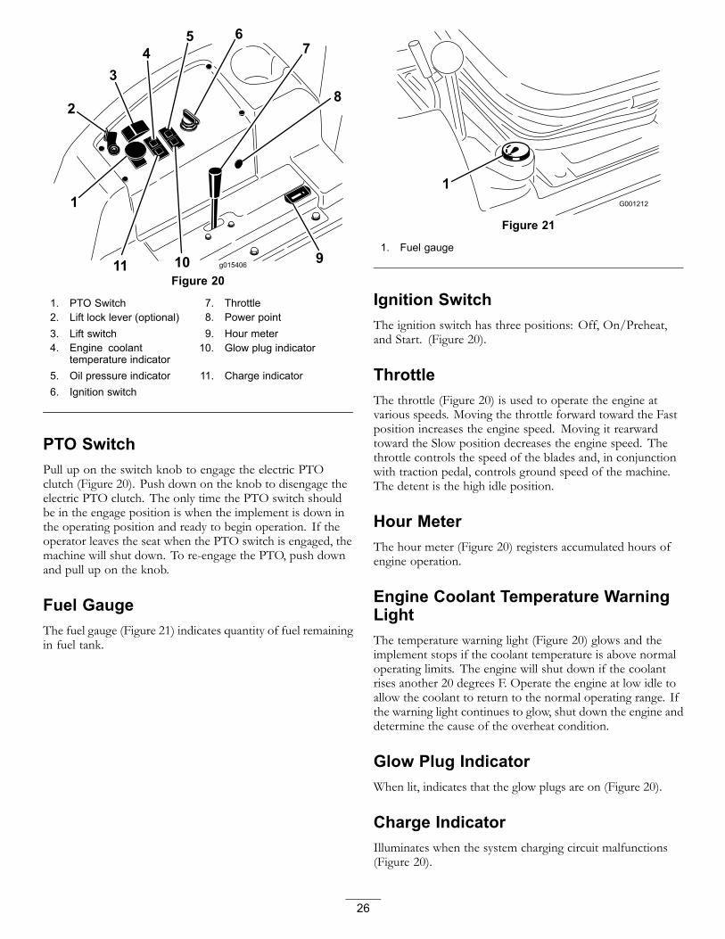
Figure 20
1. PTO Switch 7. Throttle2. Lift lock lever (optional) 8. Power point3. Lift switch 9. Hour meter4. Engine coolant
temperature indicator10. Glow plug indicator
5. Oil pressure indicator 11. Charge indicator6. Ignition switch
PTO SwitchPull up on the switch knob to engage the electric PTOclutch (Figure 20). Push down on the knob to disengage theelectric PTO clutch. The only time the PTO switch shouldbe in the engage position is when the implement is down inthe operating position and ready to begin operation. If theoperator leaves the seat when the PTO switch is engaged, themachine will shut down. To re-engage the PTO, push downand pull up on the knob.
Fuel GaugeThe fuel gauge (Figure 21) indicates quantity of fuel remainingin fuel tank.
Figure 21
1. Fuel gauge
Ignition SwitchThe ignition switch has three positions: Off, On/Preheat,and Start. (Figure 20).
ThrottleThe throttle (Figure 20) is used to operate the engine atvarious speeds. Moving the throttle forward toward the Fastposition increases the engine speed. Moving it rearwardtoward the Slow position decreases the engine speed. Thethrottle controls the speed of the blades and, in conjunctionwith traction pedal, controls ground speed of the machine.The detent is the high idle position.
Hour MeterThe hour meter (Figure 20) registers accumulated hours ofengine operation.
Engine Coolant Temperature WarningLightThe temperature warning light (Figure 20) glows and theimplement stops if the coolant temperature is above normaloperating limits. The engine will shut down if the coolantrises another 20 degrees F. Operate the engine at low idle toallow the coolant to return to the normal operating range. Ifthe warning light continues to glow, shut down the engine anddetermine the cause of the overheat condition.
Glow Plug IndicatorWhen lit, indicates that the glow plugs are on (Figure 20).
Charge IndicatorIlluminates when the system charging circuit malfunctions(Figure 20).
26
Oil Pressure Warning LightThe oil pressure warning light (Figure 20) glows when the oilpressure in engine drops below a safe level. If low oil pressureever occurs, stop the engine and determine the cause. Repairthe damage before starting the engine again.
Lift Lock LeverLock the lift switch (Figure 20), in the raised position, whenperforming maintenance on the deck or when transportingbetween mowing locations.
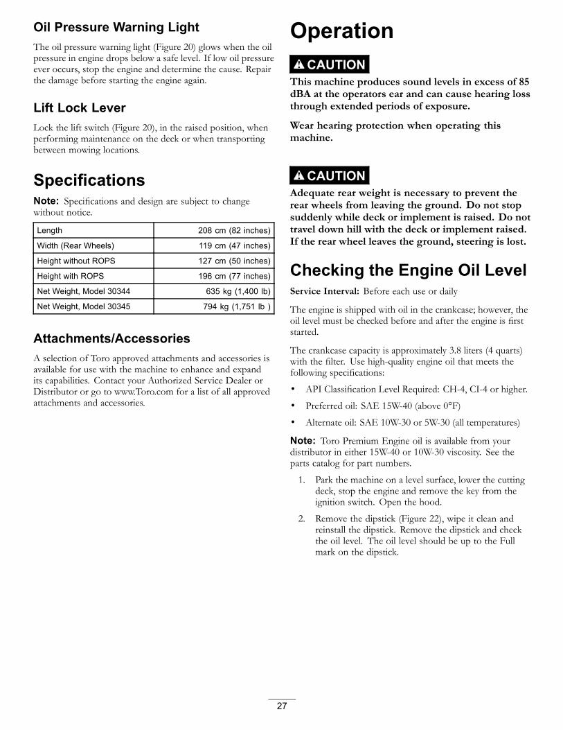
SpecificationsNote: Specifications and design are subject to changewithout notice.
Length 208 cm (82 inches)
Width (Rear Wheels) 119 cm (47 inches)
Height without ROPS 127 cm (50 inches)
Height with ROPS 196 cm (77 inches)
Net Weight, Model 30344 635 kg (1,400 lb)
Net Weight, Model 30345 794 kg (1,751 lb )
Attachments/AccessoriesA selection of Toro approved attachments and accessories isavailable for use with the machine to enhance and expandits capabilities. Contact your Authorized Service Dealer orDistributor or go to www.Toro.com for a list of all approvedattachments and accessories.
OperationCAUTION
This machine produces sound levels in excess of 85dBA at the operators ear and can cause hearing lossthrough extended periods of exposure.
Wear hearing protection when operating thismachine.
CAUTIONAdequate rear weight is necessary to prevent therear wheels from leaving the ground. Do not stopsuddenly while deck or implement is raised. Do nottravel down hill with the deck or implement raised.If the rear wheel leaves the ground, steering is lost.
Checking the Engine Oil LevelService Interval: Before each use or daily
The engine is shipped with oil in the crankcase; however, theoil level must be checked before and after the engine is firststarted.
The crankcase capacity is approximately 3.8 liters (4 quarts)with the filter. Use high-quality engine oil that meets thefollowing specifications:
• API Classification Level Required: CH-4, CI-4 or higher.
• Preferred oil: SAE 15W-40 (above 0°F)
• Alternate oil: SAE 10W-30 or 5W-30 (all temperatures)
Note: Toro Premium Engine oil is available from yourdistributor in either 15W-40 or 10W-30 viscosity. See theparts catalog for part numbers.
1. Park the machine on a level surface, lower the cuttingdeck, stop the engine and remove the key from theignition switch. Open the hood.
2. Remove the dipstick (Figure 22), wipe it clean andreinstall the dipstick. Remove the dipstick and checkthe oil level. The oil level should be up to the Fullmark on the dipstick.
27

Figure 22
1. Dipstick
3. If the oil level is below the Full mark, remove the fillcap (Figure 23) and add oil until the level reaches theFull mark on the dipstick. Do not overfill..
Figure 23
1. Oil fill
4. Install the oil fill cap and close the hood.
Checking the Cooling SystemService Interval: Before each use or daily
Clean debris off the screen and the radiator/oil cooler daily,more often if conditions are extremely dusty and dirty; referto Cleaning the Radiator and the Screen.
Check the level of the coolant in the expansion tank at thebeginning of each day before starting the engine. The capacityof the cooling system is 7.5 liters (8 quarts).
Recommended CoolantNote: Coolant must meet or exceed ASTM Standard 3306
Glycol based pre-diluted coolant (50/50 blend)or
Glycol based coolant mixed with distilled water (50/50 blend)or
Glycol based coolant mixed with good quality water (50/50 blend)
CaCO3 + MgCO3 <170 ppm
Chloride <40 ppm (CI)
Sulfer <100 ppm (SO4)
CAUTIONIf the engine has been running, pressurizedhot coolant can escape when the radiator cap isremoved and cause burns.
1. Check the level of the coolant in the expansion tank(Figure 24). The coolant level should be between themarks on the side of the tank.
Figure 24
1. Expansion tank
2. If the coolant is low, add recommended replacementcoolant, as required. Do not use water only oralcohol/methanol base coolants. Do not overfill.
3. Install expansion tank cap.
Checking the HydraulicSystemThe machines reservoir is filled at the factory withapproximately 4.7 liters (5 quarts) of high quality hydraulicfluid. Check the level of the hydraulic fluid before theengine is first started and daily thereafter. The recommendedreplacement fluid is as follows:
Toro Premium Transmission/Hydraulic Tractor Fluid(Available in 5 gallon pails or 55 gallon drums. See partscatalog or Toro distributor for part numbers.)
Alternate fluids: If the Toro fluid is not available, otherpetroleum-based Universal Tractor Hydraulic Fluids (UTHF)may be used provided its specifications fall within the listedrange for all the following material properties and it meetsindustry standards. We do not recommend the use ofsynthetic fluid. Consult with your lubricant distributor toidentify a satisfactory product Note: Toro will not assumeresponsibility for damage caused by improper substitutions,so use only products from reputable manufacturers who willstand behind their recommendation.
28

Note: Toro will not assume responsibility for damagecaused by improper substitutions, so use only productsfrom reputable manufacturers who will stand behind theirrecommendation.
Material Properties:Viscosity, ASTM D445 cSt @ 40°C 55 to 62
cSt @ 100°C 9.1 to 9.8
Viscosity Index ASTMD2270
140 to 152
Pour Point, ASTM D97 -35°F to -46°FIndustry Specifications:
API GL-4, AGCO Powerfluid 821 XL, Ford New HollandFNHA-2-C-201.00, Kubota UDT, John Deere J20C,Vickers 35VQ25, and Volvo WB-101/BM
Note: Many hydraulic fluids are almost colorless, making itdifficult to spot leaks. A red dye additive for the hydraulicsystem oil is available in 20 ml (2/3 oz) bottles. One bottle issufficient for 15-22 1iters (4-6 gallons) of hydraulic oil. Orderpart number 44-2500 from your authorized Toro distributor.
1. Position machine on a level surface. Place all controlin neutral position and start the engine. Run engine atlowest possible RPM to purge the system of air. Donot engage the PTO. Cycle steering wheel severaltimes fully to the left and right. Raise the deck toextend lift cylinders, aiming steering wheels straightforward and stop the engine.
2. Remove dipstick cap (Figure 25) from filler neck andwipe it with a clean rag. Screw dipstick cap finger-tightonto filler neck; then remove it and check level of fluid.If level is not within 13 mm (1/2 inch) from the groovein the dipstick, add enough high quality hydraulic fluidto raise level to groove mark. Do not overfill.
Figure 25
1. Hydraulic system reservoir fluid/add dipstick cap
3. Thread dipstick fill cap finger-tight onto filler neck. Itis not recommended to tighten cap with a wrench.
4. Check all hoses and fittings for leaks.
Adding FuelFuel tank capacity: 72 liters (12.8 US gallons)
Use only clean, fresh diesel fuel or biodiesel fuels with low(<500 ppm) or ultra low (<15 ppm) sulfur content. Theminimum cetane rating should be 40. Purchase fuel inquantities that can be used within 180 days to ensure fuelfreshness.
Use summer grade diesel fuel (No. 2-D) at temperaturesabove 20° F (-7° C) and winter grade (No. 1-D or No.1-D/2-D blend) below that temperature. Use of winter gradefuel at lower temperatures provides lower flash point andcold flow characteristics which will ease starting and reducefuel filter plugging.
Use of summer grade fuel above 20° F (-7° C) will contributetoward longer fuel pump life and increased power comparedto winter grade fuel.
Important: Do not use kerosene or gasoline instead ofdiesel fuel. Failure to observe this caution will damagethe engine.
WARNINGFuel is harmful or fatal if swallowed. Long-termexposure to vapors can cause serious injury andillness.
• Avoid prolonged breathing of vapors.
• Keep face away from nozzle and gas tank orconditioner opening.
• Keep fuel away from eyes and skin.
Biodiesel Ready
This machine can also use a biodiesel blended fuel of upto B20 (20% biodiesel, 80% petrodiesel). The petrodieselportion should be low or ultra low sulfur. Observe thefollowing precautions:
• The biodiesel portion of the fuel must meet specificationASTM D6751 or EN14214.
• The blended fuel composition should meet ASTM D975or EN590.
• Painted surfaces may be damaged by biodiesel blends.
• Use B5 (biodiesel content of 5%) or lesser blends in coldweather.
• Monitor seals, hoses, gaskets in contact with fuel as theymay be degraded over time.
• Fuel filter plugging may be expected for a time afterconverting to biodiesel blends.
• Contact your distributor if you wish for more informationon biodiesel.
29
DANGERIn certain conditions, fuel is extremely flammableand highly explosive. A fire or explosion from fuelcan burn you and others and can damage property.
• Fill the fuel tank outdoors, in an open area, whenthe engine is cold. Wipe up any fuel that spills.
• Never fill the fuel tank inside an enclosed trailer.
• Never smoke when handling fuel, and stay awayfrom an open flame or where fuel fumes may beignited by a spark.
• Store fuel in an approved container and keep itout of the reach of children. Never buy morethan a 180-day supply of fuel.
• Do not operate without entire exhaust system inplace and in proper working condition.
DANGERIn certain conditions during fueling, staticelectricity can be released causing a spark whichcan ignite the fuel vapors. A fire or explosion fromfuel can burn you and others and can damageproperty.
• Always place fuel containers on the ground awayfrom your vehicle before filling.
• Do not fill fuel containers inside a vehicle or ona truck or trailer bed because interior carpetsor plastic truck bed liners may insulate thecontainer and slow the loss of any static charge.
• When practical, remove equipment from thetruck or trailer and refuel the equipment with itswheels on the ground.
• If this is not possible, then refuel suchequipment on a truck or trailer from a portablecontainer, rather than from a fuel dispensernozzle.
• If a fuel dispenser nozzle must be used, keep thenozzle in contact with the rim of the fuel tankor container opening at all times until fueling iscomplete.
1. Park the machine on a level surface.
2. Using a clean rag, clean area around fuel tank cap.
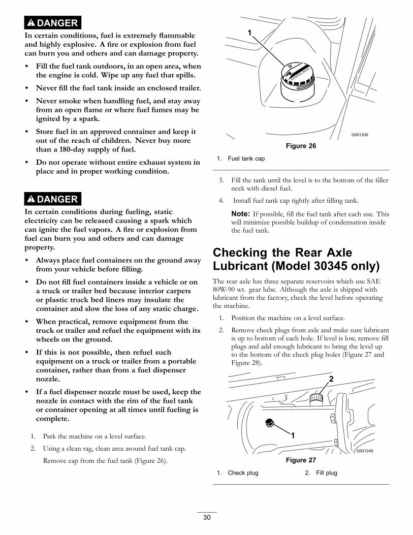
Remove cap from the fuel tank (Figure 26).
Figure 26
1. Fuel tank cap
3. Fill the tank until the level is to the bottom of the fillerneck with diesel fuel.
4. Install fuel tank cap tightly after filling tank.
Note: If possible, fill the fuel tank after each use. Thiswill minimize possible buildup of condensation insidethe fuel tank.
Checking the Rear AxleLubricant (Model 30345 only)The rear axle has three separate reservoirs which use SAE80W-90 wt. gear lube. Although the axle is shipped withlubricant from the factory, check the level before operatingthe machine.
1. Position the machine on a level surface.
2. Remove check plugs from axle and make sure lubricantis up to bottom of each hole. If level is low, remove fillplugs and add enough lubricant to bring the level upto the bottom of the check plug holes (Figure 27 andFigure 28).
Figure 27
1. Check plug 2. Fill plug
30

Figure 28
1. Fill/check plug (one on each end of axle)
Checking the BidirectionalClutch Lubricant (Model 30345only)1. Position the machine on a level surface.
2. Rotate the clutch (Figure 29) so that the check plug(shown in the 12 o'clock position) is positioned at 4o'clock.
Figure 29
1. Bidirectional clutch 2. Check plug
3. Remove the check plug.
The fluid level should be up to the hole in the clutch. Ifthe fluid level is low, add Mobil Fluid 424. The clutchshould be approximately 1/3 full.
4. Install the check plug.
Note: Do not use engine oil (i.e. 10W30) in thebidirectional clutch. Anti-wear and extreme pressureadditives will cause undesirable clutch performance.
Note: Determine the left and right sides of themachine from the normal operating position.
Using the Rollover ProtectionSystem (ROPS)
WARNINGTo avoid injury or death from rollover: keep theroll bar in the raised locked position and use theseat belt.
Ensure that the rear part of the seat is secured withthe seat latch.
WARNINGThere is no rollover protection when the roll bar isin the down position.• Lower the roll bar only when absolutely
necessary.• Do not wear the seat belt when the roll bar is
in the down position.• Drive slowly and carefully.• Raise the roll bar as soon as clearance permits.• Check carefully for overhead clearances (i.e.
branches, doorways, electrical wires) beforedriving under any objects and do not contactthem.
• Lower roll bar slowly so damage to hood doesnot occur.
Important: Lower the roll bar only when absolutelynecessary.1. To lower the roll bar, remove the hairpin cotter pins
and remove the two pins (Figure 30).
Figure 30
1. Roll bar 3. Hairpin cotter pin2. Pin
2. Lower the roll bar to the down position.3. Install the two pins and secure them with the hairpin
cotter pins (Figure 30).
31
4. To raise the roll bar, remove the hairpin cotter pins andremove the two pins (Figure 30).
5. Raise the roll bar to the upright position and install thetwo pins and secure them with the hairpin cotter pins(Figure 30).
Important: Always use the seat belt when the roll baris in the raised and locked position. Do not use the seatbelt when the ROPS is in the lowered position.
Starting/Stopping the EngineImportant: The fuel system might have to be bled if anyof the following situations have occurred: the initial startup of a new machine, the engine has ceased running dueto lack of fuel, or maintenance has been performed uponfuel system components (i.e., filter replaced, separatorserviced, etc).
1. Raise the ROPS up and lock into place, sit on the seatand fasten the seat belt.
2. Ensure that the parking brake is set and the PTOswitch is in the Off position. Remove your foot fromtraction pedal and ensure that it is in neutral
3. Move the throttle control to the Fast position.
4. Turn the ignition switch to the On/Preheat position.
An automatic timer will control preheat for 6 seconds.
5. After preheating, turn the key to the Start position.Crank the engine for no longer than 15 seconds.Release the key when the engine starts. If additionalpreheating is required, turn the key to the Off position,then to the On/Preheat position. Repeat this processas required.
6. Move the throttle to idle speed or partial throttle andrun the engine until it warms up.
Important: When engine is started for the firsttime, or after an engine oil change, or overhaulof the engine, transmission, or axle, operate themachine in forward and reverse for one to twominutes. Also operate the lift lever and PTO leverto ensure proper operation of all parts. Turn thepower steering wheel to the left and right to checkthe steering response. Then shut the engine offand check fluid levels, check for oil leaks, looseparts, and any other noticeable malfunctions.
CAUTIONShut engine off and wait for all moving partsto stop before checking for oil leaks, looseparts or other malfunctions.
7. To stop engine, move the throttle control backward tothe Slow position, move the PTO switch to the Offposition and rotate ignition key to Off. Remove keyfrom the switch to prevent accidental starting.
Bleeding the Fuel System1. Park the machine on a level surface. Ensure that the
fuel tank is at least half full.
2. Unlatch and raise the hood.
DANGERUnder certain conditions, diesel fuel and fuelvapors are highly flammable and explosive. Afire or explosion from fuel can burn you andothers and can cause property damage.
• Use a funnel and fill the fuel tank outdoors,in an open area, when the engine is off andis cold. Wipe up any fuel that spills.
• Do not fill the fuel tank completely full.Add fuel to the fuel tank until the level is tothe bottom of the filler neck.
• Never smoke when handling fuel, and stayaway from an open flame or where fuelfumes may be ignited by a spark.
• Store fuel in a clean, safety-approvedcontainer and keep the cap in place.
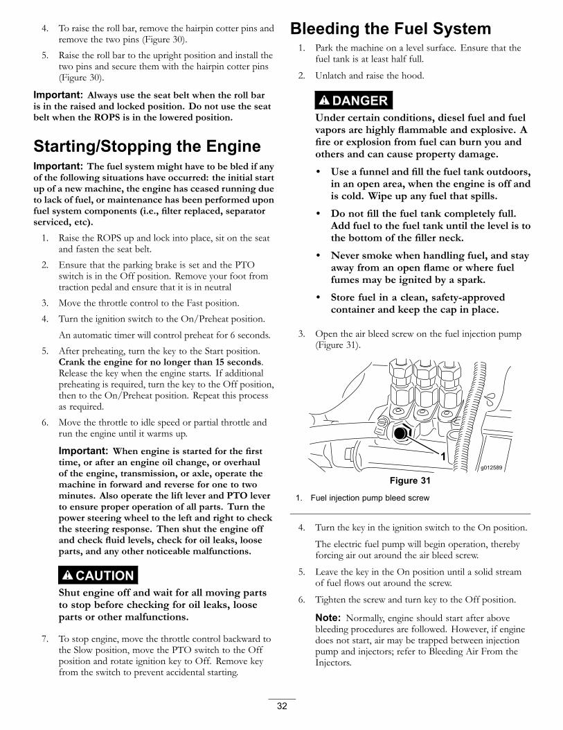
3. Open the air bleed screw on the fuel injection pump(Figure 31).
Figure 31
1. Fuel injection pump bleed screw
4. Turn the key in the ignition switch to the On position.
The electric fuel pump will begin operation, therebyforcing air out around the air bleed screw.
5. Leave the key in the On position until a solid streamof fuel flows out around the screw.
6. Tighten the screw and turn key to the Off position.
Note: Normally, engine should start after abovebleeding procedures are followed. However, if enginedoes not start, air may be trapped between injectionpump and injectors; refer to Bleeding Air From theInjectors.
32

Checking the Interlock SystemThe purpose of the safety interlock system is to prevent theengine from cranking or starting unless the traction pedalis in neutral and the PTO switch is in the Off position. Inaddition, the engine will stop when:• the PTO control is engaged with the operator off the seat;• the traction pedal is depressed with the operator off the
seat;• the traction pedal depressed with the parking brake
engaged.
CAUTIONIf the safety interlock switches are disconnected ordamaged the machine could operate unexpectedlycausing personal injury.• Do not tamper with the interlock switches.• Check the operation of the interlock switches
daily and replace any damaged switches beforeoperating the machine.
1. Move PTO switch to Off position and remove footfrom traction pedal so it is fully released.
2. Rotate the ignition key to Start. Engine should crank.If engine cranks, proceed to step 3. If engine doesnot crank, there may be a malfunction in the interlocksystem.
3. Raise off the seat and engage the PTO switch whilethe engine is running. The engine should stop within2 seconds. If engine stops, the switch is operatingcorrectly; thus, proceed to step 4. If engine does notstop, there is a malfunction in the interlock system.
4. Raise off the seat and depress the traction pedal whileengine is running and the PTO lever is disengaged.The engine should stop within 2 seconds. If enginestops, the switch is operating correctly; thus, proceedto step 5 If engine does not stop, there is a malfunctionin the interlock system.
5. Engage the parking brake. Depress the tractionpedal while engine is running and the PTO lever isdisengaged. The engine should stop within 2 seconds.If engine stops, the switch is operating correctly; thus,continue operation. If engine does not stop, there is amalfunction in the interlock system.
Pushing or Towing theMachineIn an emergency, the machine can be pushed or towed for avery short distance. However, Toro does not recommend thisas standard procedure.
Important: Do not push or tow the machine faster than2 to 3 mph because the transmission may be damaged.
If the machine must be moved a considerable distance,transport it on a truck or trailer. Whenever the machineis pushed or towed, the by-pass valve must be open.
1. Loosen the knob and remove the access cover at therear of the seat mounting plate (Figure 32).
Figure 32
1. Access cover knob
2. Press and hold the pins located in the center of the 2check valve assemblies in the top of the transmission(Figure 33) while pushing or towing the machine.Figure 33 is shown with seat and seat mounting plateremoved.
Figure 33
1. Transmission check valve by-pass pins (2)
3. Start the engine momentarily after the repairs arecompleted and make sure the pins are in the fulldisengaged (fully up) position.
Important: Running the machine with theby-pass valve open will cause the transmission tooverheat.
4. Install the access cover.
33

Standard Control Module(SCM)The Standard Control Module is a potted electronic deviceproduced in a one size fits all configuration. The moduleuses solid state and mechanical components to monitor andcontrol standard electrical features required for safe productoperation.
The module monitors inputs including neutral, parking brake,PTO, start, backlap, and high temperature. The moduleenergizes outputs including PTO, Starter, and ETR (energizeto run) solenoid.
The module is divided into inputs and outputs. Inputs andoutputs are identified by yellow LED indicators mounted onthe printed circuit board.
The start circuit input is energized by 12 VDC. All otherinputs are energized when the circuit is closed to ground.Each input has a LED that is illuminated when the specific
circuit is energized. Use the input LED's for switch and inputcircuit troubleshooting.
Output circuits are energized by an appropriate set of inputconditions. The three outputs include PTO, ETR, andSTART. Output LED's monitor relay condition indicating thepresence of voltage at one of three specific output terminals.
Output circuits do not determine output device integrity soelectrical troubleshooting includes output LED inspectionand conventional device and wire harness integrity testing.Measure disconnected component impedance, impedancethrough wire harness (disconnect at SCM), or by temporarilytest energizing the specific component.
The SCM does not connect to an external computer or handheld device, can not be re-programmed, and does not recordintermittent fault troubleshooting data.
The decal on the SCM only includes symbols. Three LEDoutput symbols are shown in the output box. All other LED'sare inputs. The chart below identifies the symbols.
Figure 34
Here are the logical troubleshooting steps for the SCM device.
1. Determine the output fault you are trying to resolve(PTO, Start, or ETR).
2. Move key switch to the On position and ensure the redpower LED is illuminated.
3. Move all input switches to ensure all LED's changestate (Seat, Brake, Traction Pedal, PTO, and Start).
4. Position input devices at appropriate position toachieve the appropriate output. Use the following logicchart to determine the appropriate input condition.
5. If specific output LED is illuminated withoutappropriate output function, check output harness,connections, and component. Repair as required.
6. If specific output LED is not illuminated, check bothfuses.
7. If specific output LED is not illuminated and inputsare in appropriate condition, install new SCM anddetermine if fault disappears.
34

Each row (across) in the logic chart below identifies input and output requirements for each specific productfunction. Product functions are listed in the left column. Symbols identify specific circuit condition including:energized to voltage, closed to ground, and open to ground.
Inputs OutputsFunction Power
OnIn
NeutralStart On Brake On PTO On In Seat Hi Temp
ShutdownHi TempWarning
Back Lap Start ETR PTO
Start — — + Ä Ä — Ä Ä N/A + + ÄRun (OffUnit)
— — Ä Ä Ä Ä Ä Ä N/A Ä + ÄRun (OnUnit)
— Ä Ä — Ä — Ä Ä N/A Ä + ÄMow — Ä Ä — — — Ä Ä N/A Ä + +
Hi TempWarning
— Ä Ä — (A) N/A + + ÄHi TempShutdown
— Ä — N/A Ä Ä Ä(-) Indicates a circuit closed to ground. - LED ON
(Ä) Indicates a circuit open to ground or de-energized - LED OFF
(+) Indicates an energized circuit (clutch coil, solenoid, or start input) LED ON.
A Blank indicates a circuit that is not involved with the logic.
(A) PTO input must be re-initiated after engine cool down (cycle key on-off)
N/A Not applicable
To troubleshoot, turn on the key without starting the engine.Identify the specific function that does not work and workacross the logic chart. Inspect the condition of each inputLED's to ensure it matches the logic chart.
If the input LED's are correct, check the output LED. If theoutput LED is illuminated but the device is not energized,measure available voltage at the output device, continuity ofthe disconnected device, and potential voltage on the groundcircuit (floating ground). Repairs will vary depending on yourfindings.
Operating Tips• Practice driving the machine before initial operation
because it has a hydrostatic transmission and itscharacteristics are different than some turf maintenancemachines. Some points to consider when operating themachine and deck are the transmission, engine speed, loadon the cutting blades, and the importance of the brakes.
• To maintain enough power for the machine and deckwhile mowing, regulate traction pedal to keep engine rpmhigh and somewhat constant. A good rule to follow is:decrease ground speed as the load on the cutting bladesincreases; and increase ground speed as load on theblades decreases. This allows the engine, working withthe transmission, to sense the proper ground speed whilemaintaining high blade tip speed necessary for goodquality-of-cut. Therefore, allow traction pedal to moveupward as engine speed decreases, and depress pedalslowly as speed increases. By comparison, when drivingfrom one work area to another-with no load and deck
raised-have throttle in Fast position and depress tractionpedal slowly but fully to attain maximum ground speed.
• Another characteristic to consider is the operation of thebrakes. The brakes can be used to assist in turning themachine; however, use them carefully, especially on softor wet grass because the turf may be torn accidentally.The brakes can be used to control the direction of thedeck when trimming along fences or similar objects. Theother benefit of the brakes is to maintain traction. Forexample; in some slope conditions, the uphill wheel slipsand loses traction. If this situation occurs, depress uphillbrake pedal gradually and intermittently until the uphillwheel stops slipping; thus, increasing traction on thedownhill wheel. If independent braking is not desired,engage the lever on left brake pedal with right pedal. Thisprovides simultaneous braking at both wheels.
• Before stopping the engine, disengage all controls andmove the throttle to the Slow position. Moving thethrottle to the Slow position reduces high engine speed,noise, and vibration. Turn the ignition key to the Offposition to stop the engine.
35

MaintenanceRecommended Maintenance Schedule(s)
Maintenance ServiceInterval Maintenance Procedure
After the first 10 hours
• Check the service brake adjustment.• Check the alternator belt tension.• Check PTO belt tension.• Change the hydraulic oil filter. Do not exceed 10 hours or you will damage thehydraulic system
• Torque wheel lug nuts.
After the first 50 hours• Change the engine oil and filter.• Check the service brake adjustment.• Check PTO belt tension.
Before each use or daily • Check the engine oil level.• Check coolant level.
Every 50 hours
• Grease the bearings and bushings.• Check battery cable connections.• Check the battery electrolyte level.• Lubricate the brake cables.
Every 150 hours • Change the engine oil and filter.
Every 200 hours
• Check steering cylinder mounting bolt torque. (Model 30345 only)• Check the rear wheel toe-in.• Inspect cooling system hoses.• Check the alternator belt tension• Check PTO belt condition and tension.• Check PTO clutch gap adjustment.• Change the hydraulic oil filter• Torque wheel lug nuts.
Every 400 hours
• Grease the transmission bypass pins.• Grease the rear axle bearings.• Service the air cleaner.• Replace the fuel filter canister.• Drain and clean the fuel tank.• Check the fuel lines and connections.• Change the rear axle lubricant.• Change the bidirectional clutch lubricant (Model 30345 only).
Every 1,500 hours• Replace moving hoses• Flush and replace cooling system fluid.• Replace the hydraulic oil.
CAUTIONIf you leave the key in the ignition switch, someone could accidently start the engine and seriously injureyou or other bystanders.
Remove the key from the ignition before you do any maintenance.
36

Daily Maintenance ChecklistDuplicate this page for routine use.
For the week of:Maintenance Check Item
Mon. Tues. Wed. Thurs. Fri. Sat. Sun.
Check Safety InterlockOperation
Make sure the ROPS is fullyraised and locked in position
Check Grass Deflector inDown Position
Check Brake Operation
Check Fuel Level
Check Engine Oil Level
Check Cooling System FluidLevel
Check Drain Water/FuelSeparator
Check Air Filter RestrictionIndicator3
Check Radiator & Screen forDebris
Check Unusual EngineNoises1
Check Unusual OperatingNoises
Check Transmission Oil Level
Check Hydraulic Hoses forDamage
Check Fluid Leaks
Check Tire Pressure
Check Instrument Operation
Check Condition of Blades
Lubricate All Grease Fittings2
Touch-up Damaged Paint
1. Check glow plug and injector nozzles, if hard starting, excess smoke or rough running is noted.
2. Immediately after every washing, regardless of the interval listed.
3. If indicator shows red
Important: Refer to your Engine Operator's Manual for additional maintenance procedures.
Notation for Areas of Concern
Inspection performed by:
Item Date Information
37
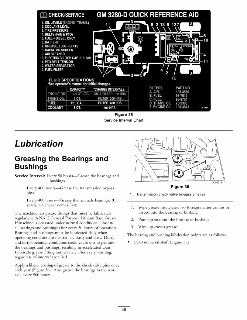
Figure 35Service Interval Chart
LubricationGreasing the Bearings andBushingsService Interval: Every 50 hours—Grease the bearings and
bushings.
Every 400 hours—Grease the transmission bypasspins.
Every 400 hours—Grease the rear axle bearings. (Oryearly, whichever comes first)
The machine has grease fittings that must be lubricatedregularly with No. 2 General Purpose Lithium Base Grease.If machine is operated under normal conditions, lubricateall bearings and bushings after every 50 hours of operation.Bearings and bushings must be lubricated daily whenoperating conditions are extremely dusty and dirty. Dustyand dirty operating conditions could cause dirt to get intothe bearings and bushings, resulting in accelerated wear.Lubricate grease fitting immediately after every washing,regardless of interval specified.
Apply a liberal coating of grease to the check valve pins onceeach year (Figure 36). Also grease the bearings in the rearaxle every 500 hours.
Figure 36
1. Transmission check valve by-pass pins (2)
1. Wipe grease fitting clean so foreign matter cannot beforced into the bearing or bushing.
2. Pump grease into the bearing or bushing.
3. Wipe up excess grease.
The bearing and bushing lubrication points are as follows:
• PTO universal shaft (Figure 37)
38

Figure 37
• Lift arm pivot bushings (Figure 38)
Figure 38
• Brake pivot bushings (Figure 39)
Figure 39
• Brake cables (drive wheel and brake pedal ends) (Figure39)
• PTO tension pivot (Figure 40)
Figure 40
• Rear PTO bearing (Figure 40)
• Transmission neutral shaft (Figure 41)
Note: 2 Wheel Drive Only
Figure 41
• Rear wheel spindle bushings (Figure 42)
Figure 42
• Steering plate bushings (Figure 43)
39

Figure 43
• Axle pin bushing (Figure 43)
• Drive shaft (3) (Figure 44)
Note: 4 Wheel Drive Only
Figure 44
• Tie rod ends (2) (Figure 45)
Figure 45
• Cylinder rod ends (2) (Figure 45)
• Steering pivots (2) (Figure 45)
• Axle pivot pin (Figure 45)
Note: Bearings rarely fail from defects in materials orworkmanship. The most common reason for failure is
moisture and contamination working its way past theprotective seals. Bearings that are greased will rely uponregular maintenance to purge harmful debris from the bearingarea. Sealed bearings rely on an initial fill of special greaseand a robust integral seal to keep contaminants and moistureout of the rolling elements.
The sealed bearings require no lubrication or short termmaintenance. This minimizes routine service requiredand reduces the potential of turf damage due to greasecontamination. These sealed bearing packages will providegood performance and life under normal use, but periodicinspections of bearing condition and seal integrity shouldbe conducted to avoid downtime. These bearings shouldbe inspected seasonally and replaced if damaged or worn.Bearings should operate smoothly with no detrimentalcharacteristics such as high heat, noise, looseness orindications of corrosion (rust).
Due to the operating conditions these bearing/seal packagesare subject to (i.e. sand, turf chemicals, water, impacts, etc.)they are considered normal wear items. Bearings that fail dueto causes other than defects in materials or workmanship aretypically not covered under warranty.
Note: Bearing life can be negatively affected by improperwash down procedures. Do not wash down the unit when itis still hot and avoid directing high-pressure or high volumespray at the bearings.
40
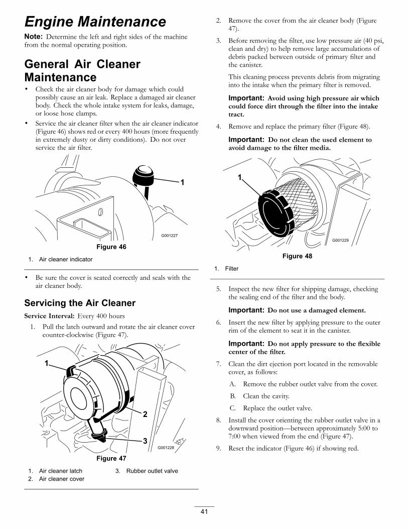
Engine MaintenanceNote: Determine the left and right sides of the machinefrom the normal operating position.
General Air CleanerMaintenance• Check the air cleaner body for damage which could
possibly cause an air leak. Replace a damaged air cleanerbody. Check the whole intake system for leaks, damage,or loose hose clamps.
• Service the air cleaner filter when the air cleaner indicator(Figure 46) shows red or every 400 hours (more frequentlyin extremely dusty or dirty conditions). Do not overservice the air filter.
Figure 46
1. Air cleaner indicator
• Be sure the cover is seated correctly and seals with theair cleaner body.
Servicing the Air CleanerService Interval: Every 400 hours1. Pull the latch outward and rotate the air cleaner cover
counter-clockwise (Figure 47).
Figure 47
1. Air cleaner latch 3. Rubber outlet valve2. Air cleaner cover
2. Remove the cover from the air cleaner body (Figure47).
3. Before removing the filter, use low pressure air (40 psi,clean and dry) to help remove large accumulations ofdebris packed between outside of primary filter andthe canister.
This cleaning process prevents debris from migratinginto the intake when the primary filter is removed.
Important: Avoid using high pressure air whichcould force dirt through the filter into the intaketract.
4. Remove and replace the primary filter (Figure 48).
Important: Do not clean the used element toavoid damage to the filter media.
Figure 48
1. Filter
5. Inspect the new filter for shipping damage, checkingthe sealing end of the filter and the body.
Important: Do not use a damaged element.6. Insert the new filter by applying pressure to the outer
rim of the element to seat it in the canister.
Important: Do not apply pressure to the flexiblecenter of the filter.
7. Clean the dirt ejection port located in the removablecover, as follows:
A. Remove the rubber outlet valve from the cover.
B. Clean the cavity.
C. Replace the outlet valve.
8. Install the cover orienting the rubber outlet valve in adownward position—between approximately 5:00 to7:00 when viewed from the end (Figure 47).
9. Reset the indicator (Figure 46) if showing red.
41

Changing the Engine Oil AndFilterService Interval: After the first 50 hours
Every 150 hours
If possible, run engine just before changing oil because warmoil flows better and carries more contaminants than cold oil.
1. Position the machine on a level surface.
2. Open the hood.
3. Set a drain pan under the oil pan and in line with thedrain plug (Figure 49).
Figure 49
1. Drain plug
4. Clean the area around the drain plug.
5. Remove the drain plug and allow oil to flow into drainpan.
6. Remove and replace the oil filter (Figure 50).
Figure 50
1. Oil filter
7. After the oil is drained, install the drain plug and wipeup any oil that is spilled.
8. Fill the crankcase with oil; refer to Checking the EngineOil Level
Fuel SystemMaintenanceNote: Refer to Filling the Fuel Tank for proper fuelrecommendations.
Servicing the Water SeparatorService Interval: Every 400 hours
Drain water or other contaminants from water separator(Figure 51) daily. Replace filter canister after every 400 hoursof operation.
1. Place a clean container under the fuel filter.
2. Loosen the drain plug on the bottom of the filtercanister.
Figure 51
1. Water separator filter canister
3. Clean the area where the filter canister mounts.
4. Remove the filter canister and clean the mountingsurface.
5. Lubricate the gasket on the filter canister with clean oil.
6. Install the filter canister by hand until the gasketcontacts mounting surface, then rotate it an additional1/2 turn.
7. Tighten the drain plug on the bottom of the filtercanister.
Cleaning the Fuel TankService Interval: Every 400 hours—Drain and clean the fuel
tank. (Or yearly, whichever comes first)
Drain and clean tank if fuel system becomes contaminated orif machine is to be stored for an extended period. Use cleandiesel fuel to flush out the tank.
42
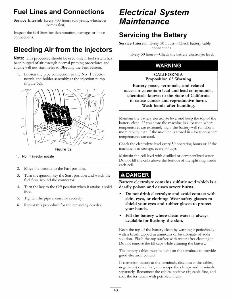
Fuel Lines and ConnectionsService Interval: Every 400 hours (Or yearly, whichever
comes first)
Inspect the fuel lines for deterioration, damage, or looseconnections.
Bleeding Air from the InjectorsNote: This procedure should be used only if fuel system hasbeen purged of air through normal priming procedures andengine will not start; refer to Bleeding the Fuel System.
1. Loosen the pipe connection to the No. 1 injectornozzle and holder assembly at the injection pump(Figure 52).
Figure 52
1. No. 1 injector nozzle
2. Move the throttle to the Fast position.
3. Turn the ignition key the Start position and watch thefuel flow around the connector.
4. Turn the key to the Off position when it attains a solidflow.
5. Tighten the pipe connector securely.
6. Repeat this procedure for the remaining nozzles.
Electrical SystemMaintenanceServicing the BatteryService Interval: Every 50 hours—Check battery cable
connections.
Every 50 hours—Check the battery electrolyte level.
WARNINGCALIFORNIA
Proposition 65 WarningBattery posts, terminals, and related
accessories contain lead and lead compounds,chemicals known to the State of Californiato cause cancer and reproductive harm.
Wash hands after handling.
Maintain the battery electrolyte level and keep the top of thebattery clean. If you store the machine in a location wheretemperatures are extremely high, the battery will run downmore rapidly than if the machine is stored in a location wheretemperatures are cool.
Check the electrolyte level every 50 operating hours or, if themachine is in storage, every 30 days.
Maintain the cell level with distilled or demineralized water.Do not fill the cells above the bottom of the split ring insideeach cell.
DANGERBattery electrolyte contains sulfuric acid which is adeadly poison and causes severe burns.• Do not drink electrolyte and avoid contact with
skin, eyes, or clothing. Wear safety glasses toshield your eyes and rubber gloves to protectyour hands.
• Fill the battery where clean water is alwaysavailable for flushing the skin.
Keep the top of the battery clean by washing it periodicallywith a brush dipped in ammonia or bicarbonate of sodasolution. Flush the top surface with water after cleaning it.Do not remove the fill caps while cleaning the battery.
The battery cables must be tight on the terminals to providegood electrical contact.
If corrosion occurs at the terminals, disconnect the cables,negative (-) cable first, and scrape the clamps and terminalsseparately. Reconnect the cables, positive (+) cable first, andcoat the terminals with petroleum jelly.
43
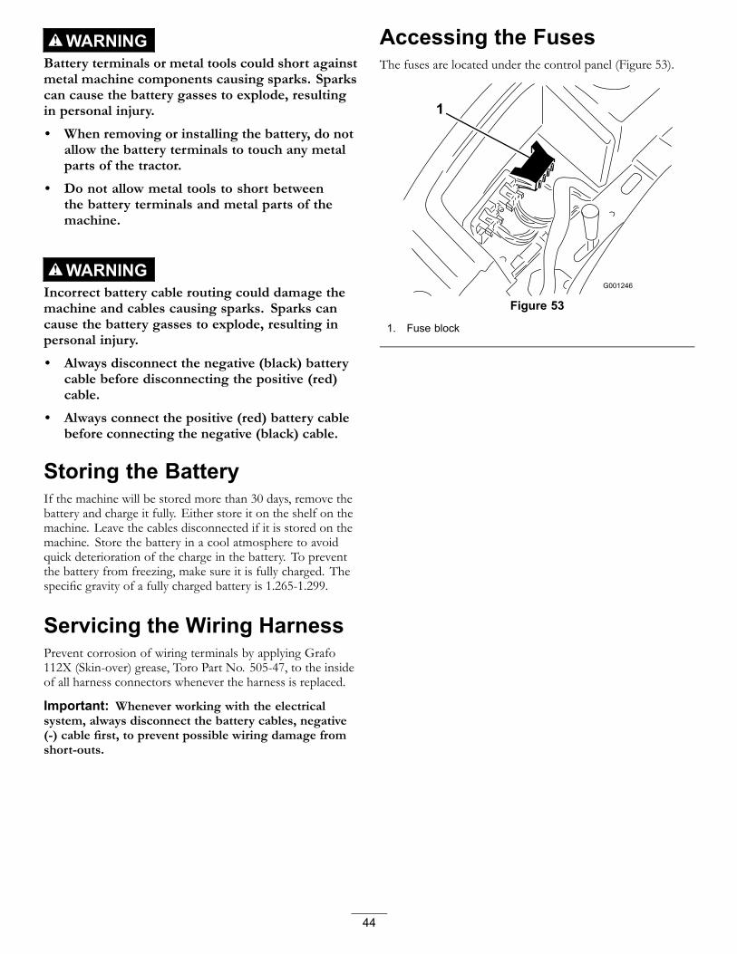
WARNINGBattery terminals or metal tools could short againstmetal machine components causing sparks. Sparkscan cause the battery gasses to explode, resultingin personal injury.
• When removing or installing the battery, do notallow the battery terminals to touch any metalparts of the tractor.
• Do not allow metal tools to short betweenthe battery terminals and metal parts of themachine.
WARNINGIncorrect battery cable routing could damage themachine and cables causing sparks. Sparks cancause the battery gasses to explode, resulting inpersonal injury.
• Always disconnect the negative (black) batterycable before disconnecting the positive (red)cable.
• Always connect the positive (red) battery cablebefore connecting the negative (black) cable.
Storing the BatteryIf the machine will be stored more than 30 days, remove thebattery and charge it fully. Either store it on the shelf on themachine. Leave the cables disconnected if it is stored on themachine. Store the battery in a cool atmosphere to avoidquick deterioration of the charge in the battery. To preventthe battery from freezing, make sure it is fully charged. Thespecific gravity of a fully charged battery is 1.265-1.299.
Servicing the Wiring HarnessPrevent corrosion of wiring terminals by applying Grafo112X (Skin-over) grease, Toro Part No. 505-47, to the insideof all harness connectors whenever the harness is replaced.
Important: Whenever working with the electricalsystem, always disconnect the battery cables, negative(-) cable first, to prevent possible wiring damage fromshort-outs.
Accessing the FusesThe fuses are located under the control panel (Figure 53).
Figure 53
1. Fuse block
44
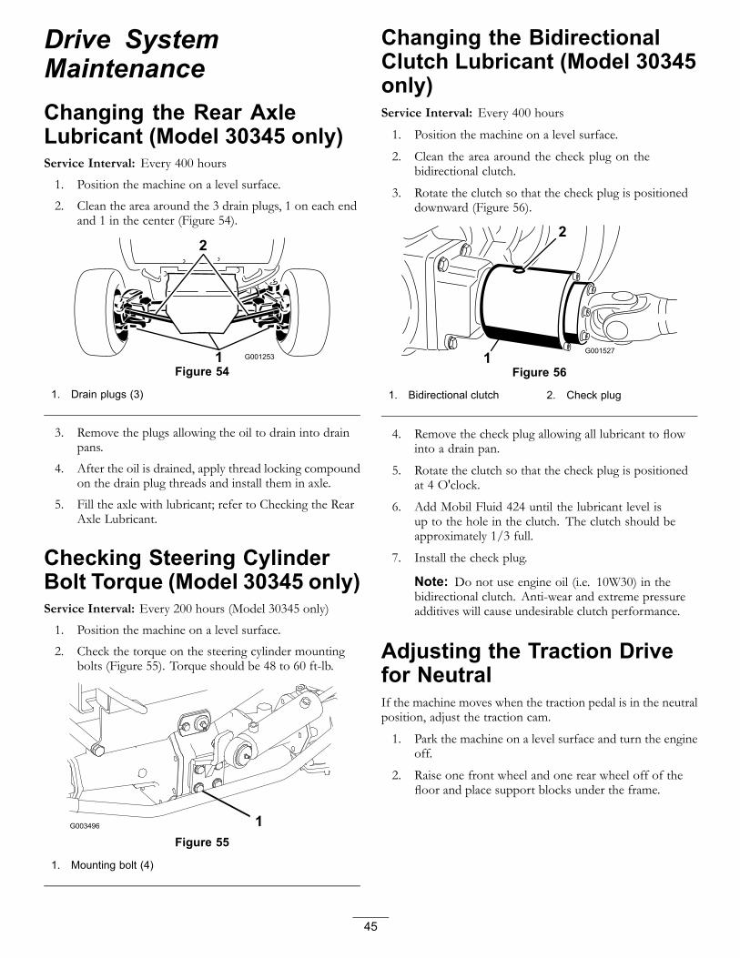
Drive SystemMaintenanceChanging the Rear AxleLubricant (Model 30345 only)Service Interval: Every 400 hours
1. Position the machine on a level surface.
2. Clean the area around the 3 drain plugs, 1 on each endand 1 in the center (Figure 54).
Figure 54
1. Drain plugs (3)
3. Remove the plugs allowing the oil to drain into drainpans.
4. After the oil is drained, apply thread locking compoundon the drain plug threads and install them in axle.
5. Fill the axle with lubricant; refer to Checking the RearAxle Lubricant.
Checking Steering CylinderBolt Torque (Model 30345 only)Service Interval: Every 200 hours (Model 30345 only)
1. Position the machine on a level surface.
2. Check the torque on the steering cylinder mountingbolts (Figure 55). Torque should be 48 to 60 ft-lb.
Figure 55
1. Mounting bolt (4)
Changing the BidirectionalClutch Lubricant (Model 30345only)Service Interval: Every 400 hours
1. Position the machine on a level surface.
2. Clean the area around the check plug on thebidirectional clutch.
3. Rotate the clutch so that the check plug is positioneddownward (Figure 56).
Figure 56
1. Bidirectional clutch 2. Check plug
4. Remove the check plug allowing all lubricant to flowinto a drain pan.
5. Rotate the clutch so that the check plug is positionedat 4 O'clock.
6. Add Mobil Fluid 424 until the lubricant level isup to the hole in the clutch. The clutch should beapproximately 1/3 full.
7. Install the check plug.
Note: Do not use engine oil (i.e. 10W30) in thebidirectional clutch. Anti-wear and extreme pressureadditives will cause undesirable clutch performance.
Adjusting the Traction Drivefor NeutralIf the machine moves when the traction pedal is in the neutralposition, adjust the traction cam.
1. Park the machine on a level surface and turn the engineoff.
2. Raise one front wheel and one rear wheel off of thefloor and place support blocks under the frame.
45
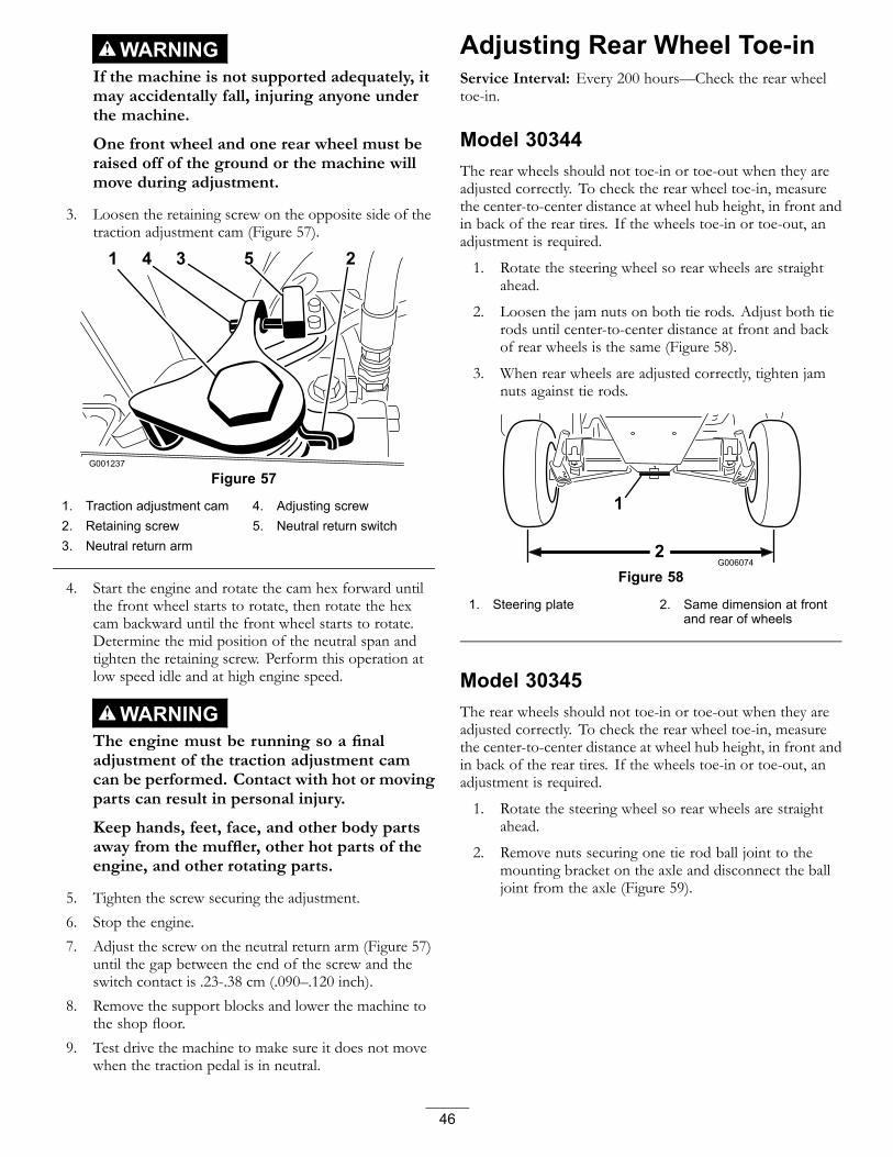
WARNINGIf the machine is not supported adequately, itmay accidentally fall, injuring anyone underthe machine.
One front wheel and one rear wheel must beraised off of the ground or the machine willmove during adjustment.
3. Loosen the retaining screw on the opposite side of thetraction adjustment cam (Figure 57).
Figure 57
1. Traction adjustment cam 4. Adjusting screw2. Retaining screw 5. Neutral return switch3. Neutral return arm
4. Start the engine and rotate the cam hex forward untilthe front wheel starts to rotate, then rotate the hexcam backward until the front wheel starts to rotate.Determine the mid position of the neutral span andtighten the retaining screw. Perform this operation atlow speed idle and at high engine speed.
WARNINGThe engine must be running so a finaladjustment of the traction adjustment camcan be performed. Contact with hot or movingparts can result in personal injury.
Keep hands, feet, face, and other body partsaway from the muffler, other hot parts of theengine, and other rotating parts.
5. Tighten the screw securing the adjustment.6. Stop the engine.7. Adjust the screw on the neutral return arm (Figure 57)
until the gap between the end of the screw and theswitch contact is .23-.38 cm (.090–.120 inch).
8. Remove the support blocks and lower the machine tothe shop floor.
9. Test drive the machine to make sure it does not movewhen the traction pedal is in neutral.
Adjusting Rear Wheel Toe-inService Interval: Every 200 hours—Check the rear wheeltoe-in.
Model 30344The rear wheels should not toe-in or toe-out when they areadjusted correctly. To check the rear wheel toe-in, measurethe center-to-center distance at wheel hub height, in front andin back of the rear tires. If the wheels toe-in or toe-out, anadjustment is required.
1. Rotate the steering wheel so rear wheels are straightahead.
2. Loosen the jam nuts on both tie rods. Adjust both tierods until center-to-center distance at front and backof rear wheels is the same (Figure 58).
3. When rear wheels are adjusted correctly, tighten jamnuts against tie rods.
Figure 58
1. Steering plate 2. Same dimension at frontand rear of wheels
Model 30345The rear wheels should not toe-in or toe-out when they areadjusted correctly. To check the rear wheel toe-in, measurethe center-to-center distance at wheel hub height, in front andin back of the rear tires. If the wheels toe-in or toe-out, anadjustment is required.
1. Rotate the steering wheel so rear wheels are straightahead.
2. Remove nuts securing one tie rod ball joint to themounting bracket on the axle and disconnect the balljoint from the axle (Figure 59).
46
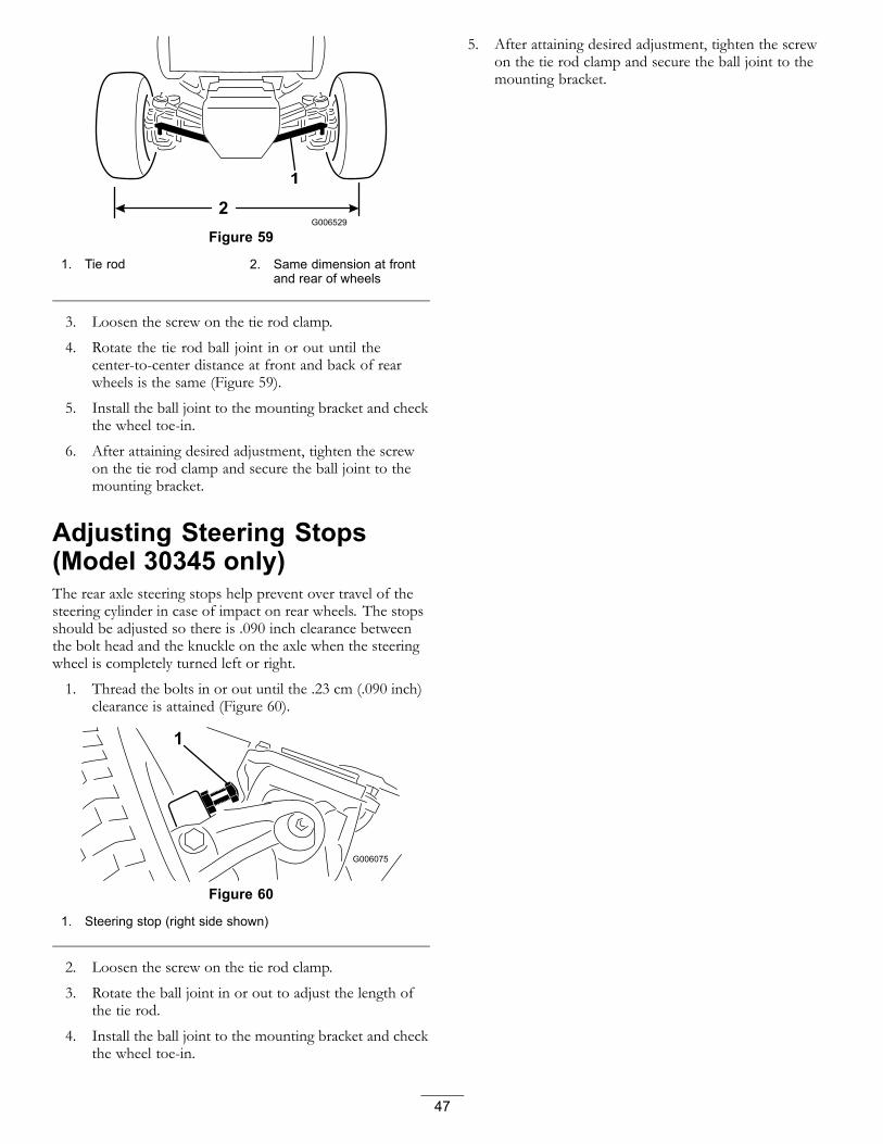
Figure 59
1. Tie rod 2. Same dimension at frontand rear of wheels
3. Loosen the screw on the tie rod clamp.
4. Rotate the tie rod ball joint in or out until thecenter-to-center distance at front and back of rearwheels is the same (Figure 59).
5. Install the ball joint to the mounting bracket and checkthe wheel toe-in.
6. After attaining desired adjustment, tighten the screwon the tie rod clamp and secure the ball joint to themounting bracket.
Adjusting Steering Stops(Model 30345 only)The rear axle steering stops help prevent over travel of thesteering cylinder in case of impact on rear wheels. The stopsshould be adjusted so there is .090 inch clearance betweenthe bolt head and the knuckle on the axle when the steeringwheel is completely turned left or right.
1. Thread the bolts in or out until the .23 cm (.090 inch)clearance is attained (Figure 60).
Figure 60
1. Steering stop (right side shown)
2. Loosen the screw on the tie rod clamp.
3. Rotate the ball joint in or out to adjust the length ofthe tie rod.
4. Install the ball joint to the mounting bracket and checkthe wheel toe-in.
5. After attaining desired adjustment, tighten the screwon the tie rod clamp and secure the ball joint to themounting bracket.
47

Cooling SystemMaintenanceCleaning the Radiator and theScreenService Interval: Every 200 hours
Every 1,500 hours
Every 1,500 hours
To prevent the engine from overheating, the screen andradiator must be kept clean. Normally, check the screen andradiator daily and, if necessary, clean any debris off theseparts. However, it will be necessary to check and clean thescreen and radiator frequently in extremely dusty and dirtyconditions.
Note: If engine shuts off due to overheating, first check theradiator and screen for excessive buildup of debris.
Clean the radiator as follows:
1. Remove the screen.
2. Working from the fan side of the radiator, blow withlow pressure (25 psi) compressed air (do not usewater). Repeat the step from the front of the radiatorand again from the fan side.
3. After the radiator is thoroughly cleaned, clean outdebris that may have collected in the channel at theradiator base.
4. Clean and install the screen.
Brake MaintenanceAdjusting the Parking BrakeInterlock Switch1. Turn the engine off and remove the ignition key. Do
not engage the parking brake.
2. Remove the knob from parking brake rod and screwsfrom the steering tower cover (Figure 61).
Figure 61
1. Steering tower cover 3. Switch mounting screws2. Parking brake knob/rod 4. Cover mounting screws
3. Slide the cover up the steering shaft to expose theparking brake switch (Figure 62).
4. Loosen the screws and nuts securing the parking brakeswitch to the left side of the steering tower (Figure 61).
5. Align the parking brake rod paddle with the switchplunger (Figure 62)
Figure 62
1. Parking brake interlockswitch
2. Parking brake rod paddle
48

6. Press down on the parking brake rod and push up onthe switch until the compressed length of the switchplunger is 0.030 inches (Figure 62, inset) . This is thedistance between the brake rod paddle and the switchplunger housing.
7. Tighten the switch mounting screws and nuts.
8. With the parking brake disengaged, the switch circuitshould have continuity. If there is no continuity, movethe switch down slightly until there is continuity.
9. Check the adjustment as follows:
A. Engage the parking brake.
B. Press the traction pedal while the engine isrunning and the PTO lever is disengaged.
The engine should stop within 2 seconds. Ifengine stops, the switch is operating correctly;thus, continue operation. If engine does not stop,there is a malfunction in the interlock system thatmust be corrected.
10. Install the steering tower cover and brake rod knob.
Adjusting the Service BrakesService Interval: After the first 10 hours
After the first 50 hours
Every 50 hours
Adjust the service brakes when there is more than 25 mm(one inch) of “free travel” of the brake pedals, or when thebrakes do not work effectively. Free travel is the distance thebrake pedal moves before braking resistance is felt.
The brakes should be checked for adjustment after the first10 hours of operation and should only need adjusting afterconsiderable use thereafter. These periodic adjustments canbe performed where the brake cable connects to the bottomof the brake pedals. When the cable is no longer adjustable,the star nut on the inside of the brake drum must be adjustedto move the brake shoes outward. However, the brake cablesmust be adjusted again to compensate for this adjustment.
1. Disengage the lock arm from the right brake pedal sothat both pedals work independently of each other.
2. To reduce the free travel of the brake pedals, tightenthe brakes by loosening the front nut on the threadedend of brake cable (Figure 63). Then tighten the rearnut to move cable backward until the brake pedals have13 mm to 25 mm (1/2 to 1 inch) of free travel.
Figure 63
1. Brake cable jam nuts
3. Tighten the front nut after the brakes are adjustedcorrectly.
49

Belt MaintenanceChecking the Alternator BeltService Interval: Every 200 hours
After the first 10 hours
Check condition and tension of alternator belt (Figure 64)after every 200 operating hours.
1. Proper tension will allow 10 mm (3/8 inch) deflectionwhen a force of 10 lb is applied on the belt, midwaybetween the pulleys.
2. If the deflection is not 10 mm (3/8 inch), loosen thealternator mounting bolts.
Figure 64
1. Alternator 2. Mounting bolt
3. Increase or decrease the alternator belt tension andtighten the bolts.
4. Check the deflection of the belt again to ensure thatthe tension is correct.
Servicing the PTO Belt
Checking the PTO Belt TensionService Interval: After the first 10 hours
After the first 50 hours
Every 200 hours
1. Turn the engine off, set the parking brake, and removethe ignition key.
2. Raise the engine hood and allow the engine to cool.
3. Loosen the tensioning rod jam nut (Figure 65).
Figure 65
1. Tensioning spring 3. Tension adjusting bolt2. Tensioning rod jam nut
4. Use a 1/2 inch wrench to tighten or loosen the belttensioning spring (Figure 65). Adjust spring to a lengthof 273 mm (7/8 inches).
5. Tighten the jam nut.
Replacing the PTO Belt1. Turn the engine off, set the parking brake, and remove
the ignition key.
2. Raise the engine hood and allow the engine to cool.
3. Loosen the tensioning rod jam nut (Figure 65).
4. Using a 1/2 inch wrench, loosen the belt tensioningspring (Figure 65) all the way.
5. Rotate the PTO pulley toward the engine and removethe belt.
6. Install the new PTO belt and tension the pulley springto 73 mm (2-7/8 inches) (Figure 65).
7. Tighten the jam nut (Figure 65) and close the hood.
50

Controls SystemMaintenanceAdjusting the PTO ClutchService Interval: Every 200 hours
1. Turn the engine off, set the parking brake, and removethe ignition key.
2. Raise the engine hood and allow the engine to cool.
3. Adjust the air gap so that a 0.015 inch feeler gaugeslides in between the clutch lining and friction platewith light pressure (Figure 66). The gap can bedecreased by turning the adjusting nut clockwise(Figure 66). The maximum service gap is 0.030 inch.Adjust all three air gaps.
Figure 66
1. Clutch 4. Electrical connector2. 0.015 inch air gap (3) 5. PTO belt3. Adjusting nut (3)
4. After all three gaps have been set, check all three again.Adjusting one gap can alter the other gaps.
Adjusting the Traction PedalThe traction pedal can be adjusted for operator comfort or toreduce the maximum reverse speed of the machine.
1. Check the traction pedal stop adjustment. The pedalstop (Figure 67) should contact the frame slightlybefore the pump reaches full stroke.
2. To adjust the pedal stop, loosen the jam nuts, pushdown on the traction pedal, and tighten the jam nutswhen the adjustment is attained.
Figure 67
1. Traction pedal stop
3. If more adjustment is required, adjust traction rod(Figure 68) as follows:
A. Remove the bolt and nut securing traction rodend to the pedal.
B. Loosen the jam nut securing rod end to thetraction rod.
C. Rotate the rod until desired length is attained.
D. Tighten the jam nut and secure the rod end to thetraction pedal with the bolt and nut removed tolock the angle of the foot pedal.
Figure 68
1. Rod end 3. Traction rod2. Jam nut
51
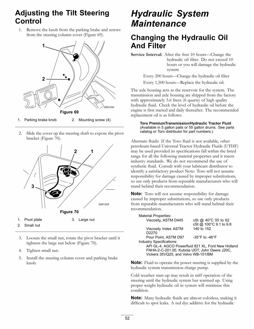
Adjusting the Tilt SteeringControl1. Remove the knob from the parking brake and screws
from the steering column cover (Figure 69).
Figure 69
1. Parking brake knob 2. Mounting screw (4)
2. Slide the cover up the steering shaft to expose the pivotbracket (Figure 70).
Figure 70
1. Pivot plate 3. Large nut2. Small nut
3. Loosen the small nut, rotate the pivot bracket until ittightens the large nut below (Figure 70).
4. Tighten small nut.
5. Install the steering column cover and parking brakeknob.
Hydraulic SystemMaintenanceChanging the Hydraulic OilAnd FilterService Interval: After the first 10 hours—Change the
hydraulic oil filter. Do not exceed 10hours or you will damage the hydraulicsystem
Every 200 hours—Change the hydraulic oil filterEvery 1,500 hours—Replace the hydraulic oil.
The axle housing acts as the reservoir for the system. Thetransmission and axle housing are shipped from the factorywith approximately 5.6 liters (6 quarts) of high qualityhydraulic fluid. Check the level of hydraulic oil before theengine is first started and daily thereafter. The recommendedreplacement oil is as follows:
Toro PremiumTransmission/Hydraulic Tractor Fluid(Available in 5 gallon pails or 55 gallon drums. See partscatalog or Toro distributor for part numbers.)
Alternate fluids: If the Toro fluid is not available, otherpetroleum-based Universal Tractor Hydraulic Fluids (UTHF)may be used provided its specifications fall within the listedrange for all the following material properties and it meetsindustry standards. We do not recommend the use ofsynthetic fluid. Consult with your lubricant distributor toidentify a satisfactory product Note: Toro will not assumeresponsibility for damage caused by improper substitutions,so use only products from reputable manufacturers who willstand behind their recommendation.
Note: Toro will not assume responsibility for damagecaused by improper substitutions, so use only productsfrom reputable manufacturers who will stand behind theirrecommendation.
Material Properties:Viscosity, ASTM D445 cSt @ 40°C 55 to 62
cSt @ 100°C 9.1 to 9.8Viscosity Index ASTMD2270
140 to 152
Pour Point, ASTM D97 -35°F to -46°FIndustry Specifications:
API GL-4, AGCO Powerfluid 821 XL, Ford New HollandFNHA-2-C-201.00, Kubota UDT, John Deere J20C,Vickers 35VQ25, and Volvo WB-101/BM
Note: Fluid to operate the power steering is supplied by thehydraulic system transmission charge pump.
Cold weather start-up may result in stiff operation of thesteering until the hydraulic system has warmed up. Usingproper weight hydraulic oil in system will minimize thiscondition.
Note: Many hydraulic fluids are almost colorless, making itdifficult to spot leaks. A red dye additive for the hydraulic
52
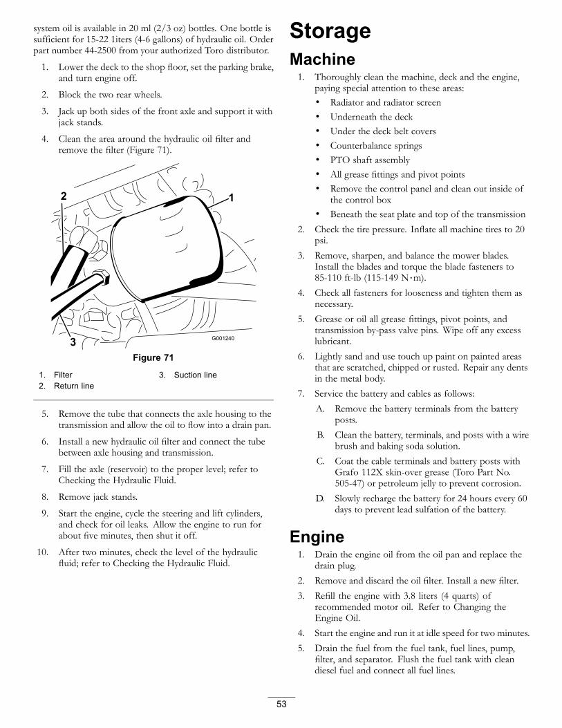
system oil is available in 20 ml (2/3 oz) bottles. One bottle issufficient for 15-22 1iters (4-6 gallons) of hydraulic oil. Orderpart number 44-2500 from your authorized Toro distributor.
1. Lower the deck to the shop floor, set the parking brake,and turn engine off.
2. Block the two rear wheels.
3. Jack up both sides of the front axle and support it withjack stands.
4. Clean the area around the hydraulic oil filter andremove the filter (Figure 71).
Figure 71
1. Filter 3. Suction line2. Return line
5. Remove the tube that connects the axle housing to thetransmission and allow the oil to flow into a drain pan.
6. Install a new hydraulic oil filter and connect the tubebetween axle housing and transmission.
7. Fill the axle (reservoir) to the proper level; refer toChecking the Hydraulic Fluid.
8. Remove jack stands.
9. Start the engine, cycle the steering and lift cylinders,and check for oil leaks. Allow the engine to run forabout five minutes, then shut it off.
10. After two minutes, check the level of the hydraulicfluid; refer to Checking the Hydraulic Fluid.
StorageMachine1. Thoroughly clean the machine, deck and the engine,
paying special attention to these areas:• Radiator and radiator screen• Underneath the deck• Under the deck belt covers• Counterbalance springs• PTO shaft assembly• All grease fittings and pivot points• Remove the control panel and clean out inside of
the control box• Beneath the seat plate and top of the transmission
2. Check the tire pressure. Inflate all machine tires to 20psi.
3. Remove, sharpen, and balance the mower blades.Install the blades and torque the blade fasteners to85-110 ft-lb (115-149 N⋅m).
4. Check all fasteners for looseness and tighten them asnecessary.
5. Grease or oil all grease fittings, pivot points, andtransmission by-pass valve pins. Wipe off any excesslubricant.
6. Lightly sand and use touch up paint on painted areasthat are scratched, chipped or rusted. Repair any dentsin the metal body.
7. Service the battery and cables as follows:A. Remove the battery terminals from the battery
posts.B. Clean the battery, terminals, and posts with a wire
brush and baking soda solution.C. Coat the cable terminals and battery posts with
Grafo 112X skin-over grease (Toro Part No.505-47) or petroleum jelly to prevent corrosion.
D. Slowly recharge the battery for 24 hours every 60days to prevent lead sulfation of the battery.
Engine1. Drain the engine oil from the oil pan and replace the
drain plug.2. Remove and discard the oil filter. Install a new filter.3. Refill the engine with 3.8 liters (4 quarts) of
recommended motor oil. Refer to Changing theEngine Oil.
4. Start the engine and run it at idle speed for two minutes.5. Drain the fuel from the fuel tank, fuel lines, pump,
filter, and separator. Flush the fuel tank with cleandiesel fuel and connect all fuel lines.
53

6. Thoroughly clean and service the air cleaner assembly.
7. Seal the air cleaner inlet and the exhaust outlet withweather proof masking tape.
8. Check the oil filler cap and fuel tank cap to ensure theyare securely in place.
54

Notes:
55

The Toro Total Coverage GuaranteeA Limited Warranty
Conditions and Products CoveredThe Toro Company and its affiliate, Toro Warranty Company, pursuantto an agreement between them, jointly warrant your Toro Commercialproduct (“Product”) to be free from defects in materials or workmanshipfor two years or 1500 operational hours*, whichever occurs first. Thiswarranty is applicable to all products with the exception of Aerators(refer to separate warranty statements for these products). Where awarrantable condition exists, we will repair the Product at no cost to youincluding diagnostics, labor, parts, and transportation. This warrantybegins on the date the Product is delivered to the original retail purchaser.* Product equipped with an hour meter.
Instructions for Obtaining Warranty ServiceYou are responsible for notifying the Commercial Products Distributor orAuthorized Commercial Products Dealer from whom you purchased theProduct as soon as you believe a warrantable condition exists. If you needhelp locating a Commercial Products Distributor or Authorized Dealer, orif you have questions regarding your warranty rights or responsibilities,you may contact us at:
Toro Commercial Products Service DepartmentToro Warranty Company8111 Lyndale Avenue SouthBloomington, MN 55420-1196
952–888–8801 or 800–952–2740E-mail: [email protected]
Owner ResponsibilitiesAs the Product owner, you are responsible for required maintenanceand adjustments stated in your Operator's Manual. Failure to performrequired maintenance and adjustments can be grounds for disallowing awarranty claim.
Items and Conditions Not CoveredNot all product failures or malfunctions that occur during the warrantyperiod are defects in materials or workmanship. This warranty does notcover the following:
• Product failures which result from the use of non-Toro replacementparts, or from installation and use of add-on, or modified non-Torobranded accessories and products. A separate warranty may beprovided by the manufacturer of these items.
• Product failures which result from failure to perform recommendedmaintenance and/or adjustments. Failure to properly maintain yourToro product per the Recommended Maintenance listed in theOperator’s Manual can result in claims for warranty being denied.
• Product failures which result from operating the Product in anabusive, negligent, or reckless manner.
• Parts subject to consumption through use unless found to bedefective. Examples of parts which are consumed, or used up,during normal Product operation include, but are not limited to, brakepads and linings, clutch linings, blades, reels, rollers and bearings(sealed or greasable), bed knives, spark plugs, castor wheels andbearings, tires, filters, belts, and certain sprayer components such asdiaphragms, nozzles, and check valves, etc.
• Failures caused by outside influence. Conditions considered to beoutside influence include, but are not limited to, weather, storagepractices, contamination, use of unapproved fuels, coolants,lubricants, additives, fertilizers, water, or chemicals, etc.
• Failure or performance issues due to the use of fuels (e.g. gasoline,diesel, or biodiesel) that do not conform to their respective industrystandards.
• Normal noise, vibration, wear and tear, and deterioration.
• Normal “wear and tear” includes, but is not limited to, damage toseats due to wear or abrasion, worn painted surfaces, scratcheddecals or windows, etc.
PartsParts scheduled for replacement as required maintenance are warrantedfor the period of time up to the scheduled replacement time for that part.Parts replaced under this warranty are covered for the duration of theoriginal product warranty and become the property of Toro. Toro willmake the final decision whether to repair any existing part or assembly orreplace it. Toro may use remanufactured parts for warranty repairs.
Deep Cycle and Lithium-Ion Battery Warranty:Deep cycle and Lithium-Ion batteries have a specified total number ofkilowatt-hours they can deliver during their lifetime. Operating, recharging,and maintenance techniques can extend or reduce total battery life. As thebatteries in this product are consumed, the amount of useful work betweencharging intervals will slowly decrease until the battery is completely wornout. Replacement of worn out batteries, due to normal consumption,is the responsibility of the product owner. Battery replacement may berequired during the normal product warranty period at owner’s expense.Note: (Lithium-Ion battery only): A Lithium-Ion battery has a part onlyprorated warranty beginning year 3 through year 5 based on the timein service and kilowatt hours used. Refer to the Operator's Manual foradditional information.
Maintenance is at Owner’s ExpenseEngine tune-up, lubrication, cleaning and polishing, replacement of filters,coolant, and completing recommended maintenance are some of thenormal services Toro products require that are at the owner’s expense.
General ConditionsRepair by an Authorized Toro Distributor or Dealer is your sole remedyunder this warranty.
Neither The Toro Company nor Toro Warranty Company is liable forindirect, incidental or consequential damages in connection with theuse of the Toro Products covered by this warranty, including anycost or expense of providing substitute equipment or service duringreasonable periods of malfunction or non-use pending completionof repairs under this warranty. Except for the Emissions warrantyreferenced below, if applicable, there is no other express warranty.All implied warranties of merchantability and fitness for use arelimited to the duration of this express warranty.
Some states do not allow exclusions of incidental or consequentialdamages, or limitations on how long an implied warranty lasts, so theabove exclusions and limitations may not apply to you. This warrantygives you specific legal rights, and you may also have other rights whichvary from state to state.
Note regarding engine warranty:The Emissions Control System on your Product may be covered bya separate warranty meeting requirements established by the U.S.Environmental Protection Agency (EPA) and/or the California AirResources Board (CARB). The hour limitations set forth above do notapply to the Emissions Control System Warranty. Refer to the EngineEmission Control Warranty Statement supplied with your product orcontained in the engine manufacturer’s documentation for details
Countries Other than the United States or CanadaCustomers who have purchased Toro products exported from the United States or Canada should contact their Toro Distributor (Dealer) to obtainguarantee policies for your country, province, or state. If for any reason you are dissatisfied with your Distributor's service or have difficulty obtainingguarantee information, contact the Toro importer.
374-0253 Rev B