GROTH PRODUCTS ROUP - Brunnbauer-Moravia, s.r.o. · API 2521 states that 1/ 2 oz. is the usual...
12
® INNOVATIVE SOLUTIONS FOR PROCESS AND LIQUID STORAGE T ANK PROTECTION GROTH PRODUCTS GROUP
Transcript of GROTH PRODUCTS ROUP - Brunnbauer-Moravia, s.r.o. · API 2521 states that 1/ 2 oz. is the usual...

®
INNOVATIVE SOLUTIONS
FOR PROCESS
AND LIQUID STORAGE
TANK PROTECTION
GROTH PRODUCTS GROUP
GROTH CORPORATION
Established in Houston, Texasin 1960, Groth has grown toemploy more than 200 associateswith three plants in Houston,Texas, Geismar, Louisiana andLake Charles, Louisiana. TheHouston plant is 81,000 squarefeet. In 1971 Groth started the“Vent Valve” division and is nowthe leading pressure/vacuumrelief valve manufacturer in theUnited States.
The three divisions of theCompany are as follows:• Groth Products Group
(GPG) ManufacturingDivision
• Representation Division• Valve Repair Division
PRESSURE/VACUUMRELIEF VALVE
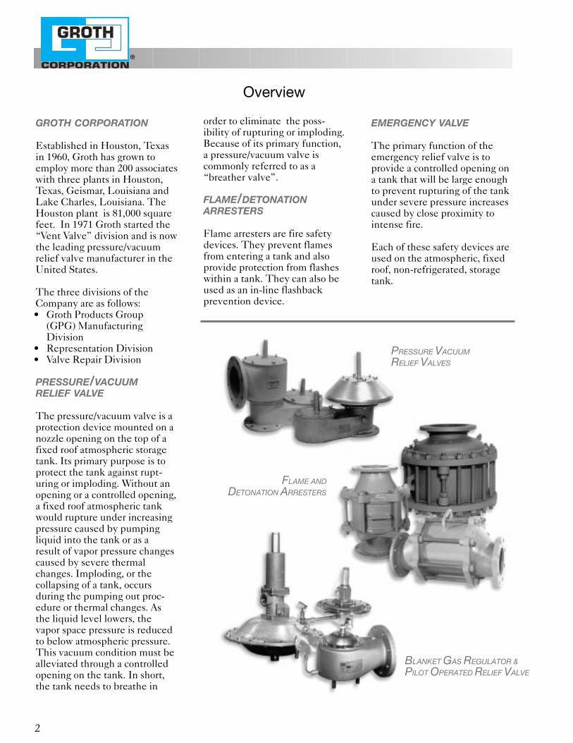
The pressure/vacuum valve is aprotection device mounted on anozzle opening on the top of afixed roof atmospheric storagetank. Its primary purpose is toprotect the tank against rupt-uring or imploding. Without anopening or a controlled opening,a fixed roof atmospheric tankwould rupture under increasingpressure caused by pumpingliquid into the tank or as aresult of vapor pressure changescaused by severe thermalchanges. Imploding, or thecollapsing of a tank, occursduring the pumping out proc-edure or thermal changes. Asthe liquid level lowers, thevapor space pressure is reducedto below atmospheric pressure.This vacuum condition must bealleviated through a controlledopening on the tank. In short, the tank needs to breathe in
order to eliminate the poss-ibility of rupturing or imploding.Because of its primary function,a pressure/vacuum valve is commonly referred to as a“breather valve”.
FLAME/DETONATIONARRESTERS
Flame arresters are fire safetydevices. They prevent flamesfrom entering a tank and alsoprovide protection from flasheswithin a tank. They can also beused as an in-line flashbackprevention device.
EMERGENCY VALVE
The primary function of theemergency relief valve is toprovide a controlled opening ona tank that will be large enoughto prevent rupturing of the tankunder severe pressure increasescaused by close proximity tointense fire.
Each of these safety devices areused on the atmospheric, fixedroof, non-refrigerated, storagetank.
®
Overview
FLAME AND
DETONATION ARRESTERS
BLANKET GAS REGULATOR &
PILOT OPERATED RELIEF VALVE
PRESSURE VACUUM
RELIEF VALVES
2
®
WHY PRESSURE/VACUUMRELIEF VALVES ARE REQUIRED
1. Saves money by saving product.2. Protects tank from over or under
pressure when sized properly.3. Protection against fire hazard
when conforming to API stan-dards.
4. Minimizes evaporation loss.5. Reduces atmospheric corrosion
of tank.6. Generally in all cases required
by OSHA, EPA, etc.
PRESSURE/VACUUM VALVESSAVE MONEY
Actually, any properly sized open-ing in the tank’s upper structureprotects the tank from damage,but utilizing a pressure and vacu-um valve also serves to accomplishother advantages. Two of themore important are: economicsavings and fire hazard protection. In 1952, American PetroleumInstitute developed a formula todetermine tank evaporative loss-es. The API equation wasformulated after the results of atotal of 256 individual tests werecompiled. Of the 256 tanks tested(1/2 with open vents and 1/2 withpressure/vacuum valves), only178 were considered valid. Theremainder were eliminatedbecause of inadequate data, obvi-ously incorrect test methods, poortank conditions, or leaky fittings.The API has a formula for calcu-lating tank breathing loss. Theprinciple factors are: turnovers peryear, true vapor pressure of theproduct, diameter of the tank infeet, the average outage in feet,the average daily ambient tem-perature change, and the paintfactor. The test was conducted ontanks containing gasoline with
pressure and vacuum valves set at1/2 oz. pressure and 1/2 oz. vacuum.API 2521 states that 1/2 oz. is theusual setting.
CALCULATING TANKPRODUCT LOSS
A multiple correlation for tanks20 feet in diameter or larger,based on model equation,derived from the tests on thetanks, yielded in the case ofgasoline:
Ly5 1 2
.68
D1.73H.51T.50FP
Where:Ly 5 the breathing loss in barrels
per year.TPY 5 turn overs per yearP 5 the true vapor pressure at bulk
liquid temperature in poundsper square inch absolute
D 5 tank diameter in feetH 5 the average outage in feetT 5 average daily ambient temper-
ature changeFp 5 the paint factor
A modification of the aboveequation was then requiredwhich would accommodatesmall-diameter tanks.
Ly5 1 2
.68
D1.73H.51T.50FPC
IN MOST CASES APRESSURE/VACUUM RELIEFVALVE WILL PAY FOR ITSELFBEFORE YOU PAY THEINVOICE
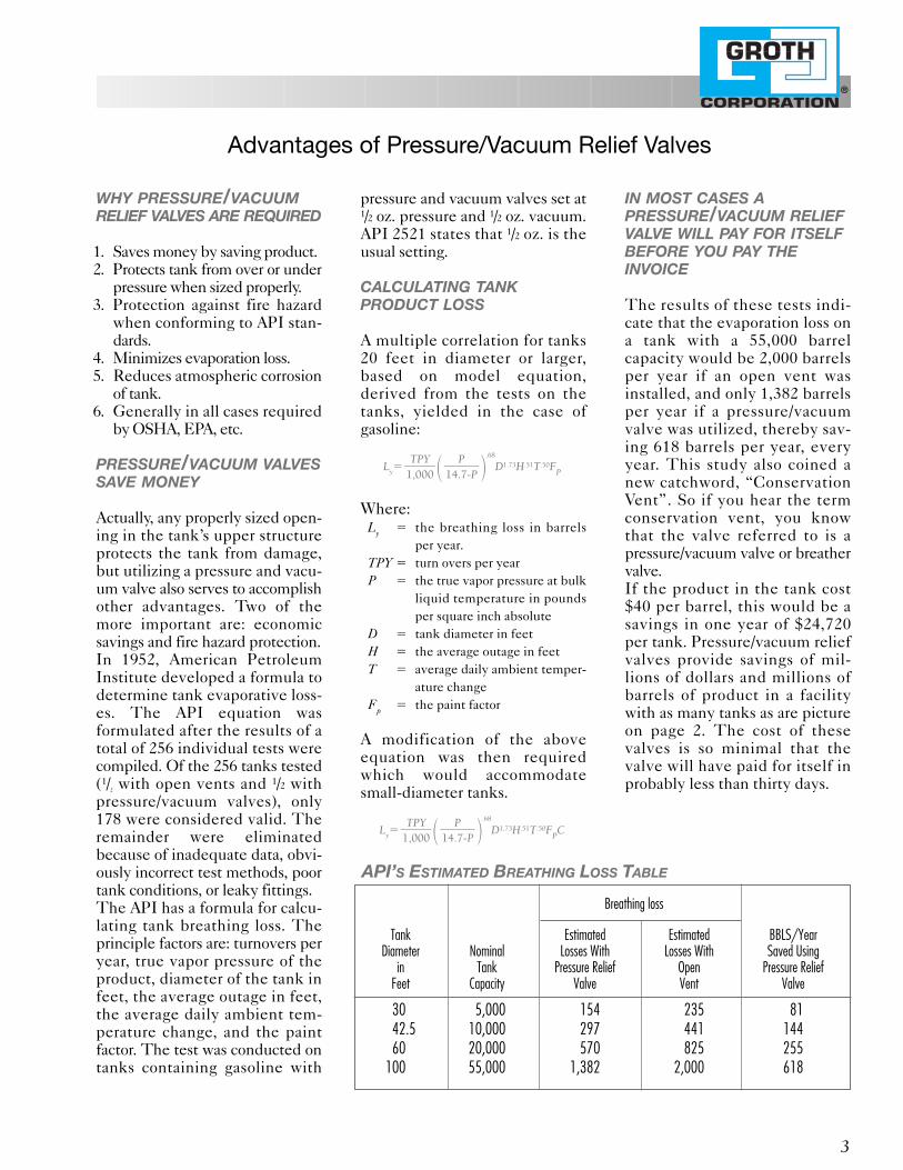
The results of these tests indi-cate that the evaporation loss ona tank with a 55,000 barrelcapacity would be 2,000 barrelsper year if an open vent wasinstalled, and only 1,382 barrelsper year if a pressure/vacuumvalve was utilized, thereby sav-ing 618 barrels per year, everyyear. This study also coined anew catchword, “ConservationVent”. So if you hear the termconservation vent, you knowthat the valve referred to is apressure/vacuum valve or breathervalve.If the product in the tank cost$40 per barrel, this would be asavings in one year of $24,720per tank. Pressure/vacuum reliefvalves provide savings of mil-lions of dollars and millions ofbarrels of product in a facilitywith as many tanks as are pictureon page 2. The cost of thesevalves is so minimal that thevalve will have paid for itself inprobably less than thirty days.
P}14.7-P
TPY}1,000
P}14.7-P
TPY}1,000
Advantages of Pressure/Vacuum Relief Valves
Breathing loss
Tank Estimated Estimated BBLS/YearDiameter Nominal Losses With Losses With Saved Using
in Tank Pressure Relief Open Pressure ReliefFeet Capacity Valve Vent Valve
30 5,000 154 235 8142.5 10,000 297 441 14460 20,000 570 825 255
100 55,000 1,382 2,000 618
API’S ESTIMATED BREATHING LOSS TABLE
3

®
An advantage of using a pres-sure/vacuum valve is that thevalve provides fire protection foryour tank. A pressure/vacuumvalve is normally closed exceptwhen venting to pressure or vac-uum conditions; and an openvent always has a free passage-way between the vapor in thetank and atmosphere. There-fore, a pressure/vacuum valve isusually closed allowing the tankvapor to reach true vapor pres-sure.Under true vapor pressure, thevapor in the tank is too rich toburn. The tank is also closed offeliminating a free passagewayfor fire or sparks to ignite thepotentially combustible vapor inthe tank. If the valve has beenactivated by excessive tank pres-sure, the now open valve iscausing a condition where anyvapors escaping are under posi-tive pressure and the fire hazardwill be kept away from the vaporcontent of the tank. If flames arein the area and the tank is in anemptying mode, the vapors arenot escaping and combustion isnot likely even though the tankhas a combustible mixture.
1. Closed tank principle. When a pressure/vacuum valve is closed, fumes are not escaping to allow combustion.
2. Pressure when open principle.When the valve is open, thevelocity of the relieving vaporis greater than the flamespeeds.
3. Over rich principle due toequilibrium being reached ina closed tank and thereforethe fumes are too rich to burn.When emptying or pumpingout of the tank, oxygen vaporsare susceptible to burning andflame arresting should beused.
4. The vacuum created duringdispensing of product willprevent fumes from escapingand consequently is generallyprotected.
REDUCED CORROSION
An additional reason for usingpressure/vacuum valves, theyhelp reduce overall corrosion inthe plant. Plant corrosion isreduced due to less productescaping from the tank andtherefore less corrosion is pro-duced by escaping vapors. Thismeans overall plant maintenanceis reduced thereby saving laborand dollars.
RECOMMENDED ANDREQUIRED
Pressure/vacuum valves are rec-ommended by API 2000 for useon atmospheric storage tanks inwhich oil with a flash pointbelow 100° F is stored. OSHAstates that tanks storing Class 1liquids shall be equipped withventing devices which shall benormally closed except underpressure or vacuum condition.Generally speaking, the majorityof the regulatory bodies dealingwith tank safety, API, OSHA,NFPA, Insurance Companiesetc. require installation of thesedevices on flammable liquidstorage tanks.
Advantages of Pressure/Vacuum Relief Valves
4
BASIC FIRE PROTECTION
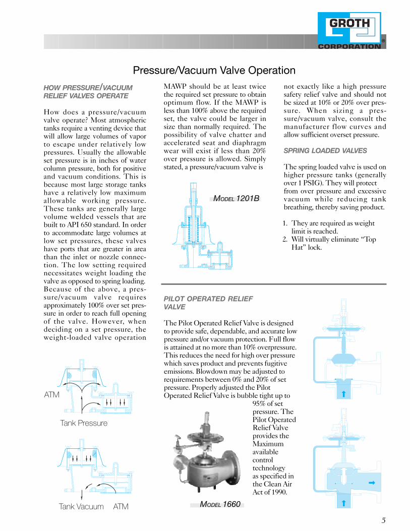
HOW PRESSURE/VACUUMRELIEF VALVES OPERATE
How does a pressure/vacuumvalve operate? Most atmospherictanks require a venting device thatwill allow large volumes of vaporto escape under relatively lowpressures. Usually the allowableset pressure is in inches of watercolumn pressure, both for positiveand vacuum conditions. This isbecause most large storage tankshave a relatively low maximumallowable working pressure.These tanks are generally largevolume welded vessels that arebuilt to API 650 standard. In orderto accommodate large volumes atlow set pressures, these valveshave ports that are greater in areathan the inlet or nozzle connec-tion. The low setting requirednecessitates weight loading thevalve as opposed to spring loading.Because of the above, a pres-sure/vacuum valve requiresapproximately 100% over set pres-sure in order to reach full openingof the valve. However, whendeciding on a set pressure, theweight-loaded valve operation
MAWP should be at least twicethe required set pressure to obtainoptimum flow. If the MAWP isless than 100% above the requiredset, the valve could be larger insize than normally required. Thepossibility of valve chatter andaccelerated seat and diaphragmwear will exist if less than 20%over pressure is allowed. Simplystated, a pressure/vacuum valve is
not exactly like a high pressuresafety relief valve and should notbe sized at 10% or 20% over pres-sure. When sizing a pres-sure/vacuum valve, consult themanufacturer flow curves andallow sufficient overset pressure.
SPRING LOADED VALVES
The spring loaded valve is used onhigher pressure tanks (generallyover 1 PSIG). They will protect from over pressure and excessivevacuum while reducing tankbreathing, thereby saving product.
1. They are required as weightlimit is reached.
2. Will virtually eliminate “TopHat” lock.
®
Pressure/Vacuum Valve Operation
5
MODEL 1201B
ATM
ATMTank Vacuum
Tank Pressure
PILOT OPERATED RELIEFVALVE
The Pilot Operated Relief Valve is designedto provide safe, dependable, and accurate lowpressure and/or vacuum protection. Full flowis attained at no more than 10% overpressure.This reduces the need for high over pressurewhich saves product and prevents fugitiveemissions. Blowdown may be adjusted torequirements between 0% and 20% of setpressure. Properly adjusted the PilotOperated Relief Valve is bubble tight up to
95% of setpressure. ThePilot OperatedRelief Valveprovides theMaximumavailable control technology as specified inthe Clean AirAct of 1990.
MODEL 1660
®
API Standard 2000 for VentingAtmospheric and Low Pressure storage Tanks
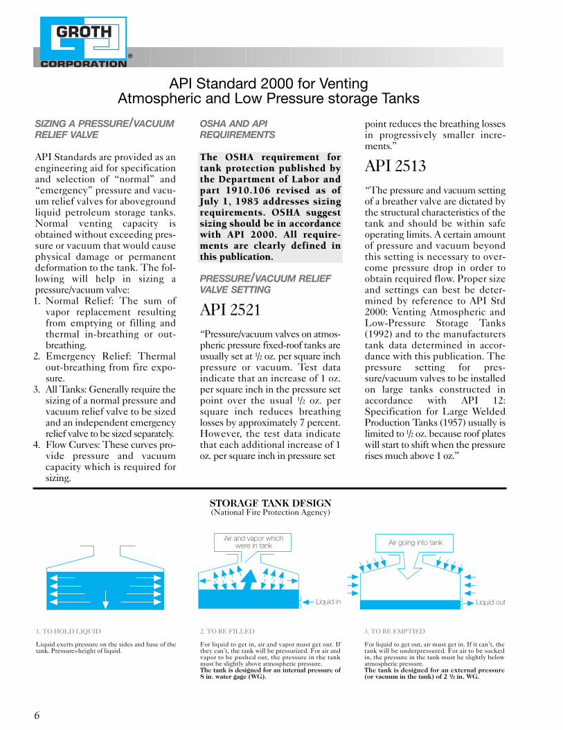
1. TO HOLD LIQUID
Liquid exerts pressure on the sides and base of thetank. Pressure=height of liquid.
2. TO BE FILLED
For liquid to get in, air and vapor must get out. Ifthey can’t, the tank will be pressurized. For air andvapor to be pushed out, the pressure in the tankmust be slightly above atmospheric pressure.The tank is designed for an internal pressure of8 in. water gage (WG).
3. TO BE EMPTIED
For liquid to get out, air must get in. If it can’t, thetank will be underpressured. For air to be suckedin, the pressure in the tank must be slightly belowatmospheric pressure.The tank is designed for an external pressure(or vacuum in the tank) of 2 1/2 in. WG.
6
Air and vapor which were in tank
Liquid in
Air going into tank
Liquid out
STORAGE TANK DESIGN(National Fire Protection Agency)
SIZING A PRESSURE/VACUUMRELIEF VALVE
API Standards are provided as anengineering aid for specificationand selection of “normal” and“emergency” pressure and vacu-um relief valves for abovegroundliquid petroleum storage tanks.Normal venting capacity isobtained without exceeding pres-sure or vacuum that would causephysical damage or permanentdeformation to the tank. The fol-lowing will help in sizing apressure/vacuum valve:1. Normal Relief: The sum of
vapor replacement resultingfrom emptying or filling andthermal in-breathing or out-breathing.
2. Emergency Relief: Thermalout-breathing from fire expo-sure.
3. All Tanks: Generally require thesizing of a normal pressure andvacuum relief valve to be sizedand an independent emergencyrelief valve to be sized separately.
4. Flow Curves: These curves pro-vide pressure and vacuumcapacity which is required forsizing.
OSHA AND APIREQUIREMENTS
The OSHA requirement fortank protection published bythe Department of Labor andpart 1910.106 revised as ofJuly 1, 1985 addresses sizingrequirements. OSHA suggestsizing should be in accordancewith API 2000. All require-ments are clearly defined inthis publication.
PRESSURE/VACUUM RELIEFVALVE SETTING
API 2521“Pressure/vacuum valves on atmos-pheric pressure fixed-roof tanks areusually set at 1/2 oz. per square inchpressure or vacuum. Test dataindicate that an increase of 1 oz.per square inch in the pressure setpoint over the usual 1/2 oz. persquare inch reduces breathinglosses by approximately 7 percent. However, the test data indicatethat each additional increase of 1oz. per square inch in pressure set
point reduces the breathing lossesin progressively smaller incre-ments.”
API 2513“The pressure and vacuum settingof a breather valve are dictated bythe structural characteristics of thetank and should be within safeoperating limits. A certain amountof pressure and vacuum beyondthis setting is necessary to over-come pressure drop in order toobtain required flow. Proper sizeand settings can best be deter-mined by reference to API Std2000: Venting Atmospheric andLow-Pressure Storage Tanks(1992) and to the manufacturerstank data determined in accor-dance with this publication. Thepressure setting for pres-sure/vacuum valves to be installedon large tanks constructed inaccordance with API 12:Specification for Large WeldedProduction Tanks (1957) usually islimited to 1/2 oz. because roof plateswill start to shift when the pressurerises much above 1 oz.”

FLAME ARRESTER
A flame arrester is a safety deviceinstalled on a nozzle on top of atank when the flash point of thestored product is lower than thepossible tank temperature. Amajority of the time, a “vent toatmosphere” pressure/vacuumvalve is installed on top of theflame arrester. A flame arrester isalso used as in-line safety device
where combustible gases are trans-ported through low pressure pipelines to actual combustion, as in anincinerator or flare or where com-bustion fumes are vented throughpiping to atmosphere where light-ning can cause a flame. Flamearresters should be designed tostop tank farm fires caused bylightning, sparking, or actual flamein the immediate tank area, and toprevent flashbacks in lines. Inorder to accomplish the above, aflame arrester must act as a barrier(stop a flame), a flame holder(contain the flame at the barrier),and dissipate heat in order to pre-vent auto ignition on the downside of the flame arrester.
In order to be an effective flameprevention device, a flame arrestermust have a quenching orhydraulic diameter small enoughto stop the flame created by thecombustible gas. Each combustible gas has a differentrequired hydraulic diameter tobe able to stop the flame. The hydraulic diameter of Groth Flame Arresters is .048"(1.23 mm).
In addition to stopping the flame,an arrester must be able to dissi-pate heat. Flame element massensures that hot gases above theauto ignition temperature neverreach the downstream side of theflame arrester.
With an in-line installation, structural integrity is important toinsure safety if a detonation shouldoccur. Proper gasketing to insurean oxygen free environment in theevent of a detonation is also impor-tant. Unless a flame arrester meetsor exceeds the above mentioneddesign criteria, it is not a true flamearrester.
DETONATION ARRESTER
A detonation arrester is anothersafety device installed in apiping system. A detonation isdefined as a flame front propa-gating through a flammable gasor vapor at a velocity equal to orgreater than the speed of sound.A detonation arrester should beinstalled when the source of aflash back is greater than tenpipe diameters from the installa-tion of the arrester or when thereis a possible restriction in theline. Groth Detonation FlameArresters are Bi-Directional andcan be installed in a vertical orhorizontal piping installation.The model 7658A has been successfully tested and USCG
approved as a Type IIDetonation Flame Arrester suitable for applications wherestationary flames may rest on the element.
AIR OPERATED RELIEF VALVE
Air operated relief valves areused to replace weight loadedand pilot operated valves insevere applications wherepolymerization and crystalizationmay take place and plug as wellas corrode the pilot valve. Thepressure switch coupled with asolenoid valve and using plantinstrument air instead of corro-sive product vapor provides abubble tight seal in the valve.
Flame and Detonation Arresters
7
®
MODEL 1520
MODEL 7658A

®
8
Manifolded Piping
Flame front travelingthrough piping system
StorageTank
StorageTank
StorageTank
StorageTank
DetonationArrester
VaporDestruction
Unit
Flame orDetonation
Arrester
TYPICAL VAPOR RECOVERY SYSTEM
EMERGENCY VALVES
Emergency valves are requiredby API on storage tanks in orderto protect the tank against exces-sive pressure caused by externalfire exposure or flashes withinthe tank.The excessive pressurecaused by an external fire is gen-erally because an adjacent tankis on fire or some other structurein close proximity is on fire.Flashes are generally caused bya chemical reaction in the tank.Regardless of the cause of theexcessive pressure, an openinglarger than the normal pressure/vacuum valve is necessary inorder to carry off the additional
volume resulting from the fireexposure the tank is experienc-ing. API 2000 states emergencyventing my be accomplished bythe use of:
1. Larger or additional openvents.
2. Larger or additional pressure/vacuum valves orpressure relief valves.
3. A gage hatch which permitsthe cover to lift under abnormal internal pressure.
4. A manhole cover which permits the cover to lift underabnormal internal pressure.(ERV Model 2000/2400)
5. A connection between theroof and shell which is weakerthan the weakest vertical jointin the shell or shell to bottomconnection (weak roof to shellweld).
MODEL 2000
VAPOR RECOVERY SYSTEM
With the implementation of the Clean Air Act of 1990, most Liquid Product Storage terminals and hydrocarbon processing plants must control evaporative hydrocarbon emissions from loading and storageoperations. Two types of recognized technologies are vapor recovery using carbon absorption or vapor combustion. Both systems require pressure/vacuum valves and flame or detonation arresters to minimizeemissions and maximize safety.

®
9
GAS BLANKETING
The Groth Blanket GasRegulator ensures that a constantgas pressure is maintained in thevapor space of a storage tank.When liquid is removed from atank or the temperature is
reduced, a vacuum would bedeveloped. With the GrothBlanket Gas Regulator, a blanketgas is supplied to prevent any vacuum from developing and tomaintain the desired blanket pressure. In addition to preventingoutside air and moisture fromentering the storage vessel, a blanket gas pressure, as low as1–2"W.C., reduces the evaporation ofthe stored product to a negligibleamount. The result would notonly conserve product but wouldalso greatly reduce emissions. Theadvantages are in addition to thefire protection that is provided.
Vapor Emission Reduction
GAUGE
SENSE LINE
FLOW
PILOT OPERATEDPRESSURE / RELIEF VALVE
WITH VACUUM RELIEF2” W.C. TO 15 PSIG SETTING
EMERGENCY RELIEF VALVE3” W.C. TO 15 PSIG SETTING
BLANKET GAS REGULATOR200 PSIG TO 1/2” WC
WITH ONE REGULATOR
OUTLETINLET
OPEN
FNPT REMOTESENSE PORT1"2
OUTLETINLET
CLOSED
FNPT REMOTESENSE PORT1"2
PILOT OPERATEDPRESSURE/RELIEF VALVE
WITH VACUUM RELIEF2” W.C. TO 15 PSIG SETTING
CONCLUSION
Tank protection equipment is specialized. Understanding thisequipment and how it should be applied will ensure that yourstorage tank is protected properly from any number of potentialhazards. Protection from rupturing or imploding, and protectionfrom fire hazards are the major considerations. Just as importantshould be the environmental and conservation features thisequipment affords your company.
Electronic CatalogPC-compatible electronic catalog and technical data.Makes valve selection andspecification simple. Includessizing program for P/V valvesper API 2000.
Cal-Q-Size 2000Sizing System Software.IBM CompatibleCalculates in accordancewith API Standard 2000.
CLEAN AIR ACT OF 1990 METHOD 21 LEAK TEST
The 1990 ammendment to the 1998 Clean Air Act, requires the emissions of any of the identified volatile organic compunds (VOC) be kept to under 500 parts per million (PPM). Method 21 is the leaktest procedure required to be utilized in order to detect rate of leakage.Using Groth Corporation pilot operated devices with the film seatoption, and the Groth blanket gas regulator provides overpressure orunderpressure protection for liquid storage tanks while assuring yourcompliance to the Clean Air Act.

Fiberglass ValvesMost Groth valves can be constructed of fiberglass.
Page 160
10
Model 1560Extreme service valveModular designPressure reliefHigh flow capacitySizes: 2" through 12"Pressure settings: 3 OZ./in.2
through 15 PSIGPage 670
Model 1360 AVacuum breakerModular designSide mountModular designSizes: 3" through 14"Vacuum settings: 1/2 OZ./in.2
to 12 PSIG
Page 330
Model 1300 AVacuum breakerModular designSizes: 2" through 12"Vacuum settings: 1/2 OZ./in.2
to 12 PSIG
Page 320
Pilot Operated Relief Valves
Pressure/Vacuum Relief Valves
Model 1200 APressure/Vacuum Relief ValveModular designSizes: 2" through 12"Pressure settings: 1/2 OZ./in.2
to 15 PSIGVacuum settings: 1/2 OZ./in.2
to 12 PSIGPage 100
Model 1220 APressure/Vacuum Relief ValvePipe-away featureModular designSizes: 2" through 12"Pressure settings: 1/2 OZ./in.2to 15 PSIGVacuum settings: 1/2 OZ./in.2to 12 PSIG
Page 120
Model 1000 SeriesPressure/Vacuum Relief ValveCommon pipe-in/out featurePressure settings: 1/2 OZ./in.2
to 15 PSIGVacuum settings: 1/2 OZ./in.2
to 12 PSIG
Page 150
Pressure Relief Valves
Model 1260 APressure Relief ValveModular designPipe-away featureSizes: 2" through 12"Pressure settings: 1/2 OZ./in.2
to 15 PSIG
Page 300
Model 2300 SeriesPressure Relief ValveModular designSizes: 2" through 12"Pressure settings: 1/2 OZ./in.2
to 15 PSIG
Page 310
Model 1420Pressure/Vacuum Relief ValveModular designPressure & vacuum reliefHigh flow capacitySizes: 2" through 12"Pressure settings: 3 OZ./in.2through 15 PSIGVacuum settings: 1/2 OZ./in.2to 12 PSIG
Page 650
Model 1660Pressure Relief ValveHigh flow capacitySizes: 2" through 12"Pressure settings: 2" W.C.through 15 PSIG
Page 600
Available in aluminum (type 356), carbon steel, stainless
GR
OTH
MA
NU
FA
CTU
RED
PR
OD
UC
TS
Model 2500Emergency Relief ValveSizes: 18", 20" and 24"Pressure settings: 8 OZ./in.2
to 15 PSIG
Vacuum Relief Valves

Flame Trap Assemblies
Flame and Detonation Arresters
Model 7618Flame arrester (vertical design)FM approvedSizes: 2" through 60"
Available with weather hood.
Page 200
Model 7628Flame arrester (horizontal design)FM approvedSizes: 2" through 30"
Page 200
Model 7658 ADetonation arrester(horizontal design)Coast Guard approvedSizes: 2" through 24"
Page 230
Model 7622Flame checkSizes: 1/2" through 1-1/2"
Page 210
Emergency Relief Valves
Model 2301APressure Relief ValveSizes: 2" through 12"Pressure settings: 1/2 OZ./in.2to 15 PSIG
Page 310
Model 2000Emergency relief manhole coverSizes: 16", 20" and 24"Pressure settings: 1-1/2 OZ./in.2 to 16 OZ./in.2Also available with vacuumbreaker.
Page 400
Model 2450Emergency relief manholecover with hinged cover withvacuum breakerSizes: 20" through 24"Vacuum settings: 1/2 OZ./in.2to 4 OZ./in.2Pressure settings: 2 OZ./in.2to 8 OZ./in.2Also available pressure only.
Page 420
Model 2100High pressure emergencyrelief valveSizes: 16", 20" and 24"Pressure settings: 1 PSIGto 15 PSIG
Page 410
11
s steel, fiberglass, and other materials, in most models.
Model 8500AFlame Trap AssemblySizes: 2" through 12"
Page 250
Model 8400ABack Pressure Regulator andFlame Trap AssemblySizes: 2" through 12"
Page 240
GR
OTH
MA
NU
FA
CTU
RED
PR
OD
UC
TS
Model 3000 SeriesBlanket Gas Regulator.Regulates and controlsinert gas blanket in storage tanks.Setting from 1/2" W.C.to 10 PSIG.
Page 730
Blanket Gas Regulator

Additional Products
Model 6000 SeriesGauge hatch.Sizes: 4" through 10".
Page 360
Model 8110Back Pressure Check ValveSizes 2" through 12"
Page 530
Pressure/Vacuum Relief Valve Test StandProvides convenient, accurate testing and setting ofP/V valves or high pressure relief valves. Includes leak testing.
Page 500 - 515
© Copyright 1998 Groth Corporation Printed in the U.S.A.
Visit us at our internet site:http://www.grothcorp.com
Groth E-mail address: [email protected]
Form No. 7.5M798
12
GR
OTH
MA
NU
FA
CTU
RED
PR
OD
UC
TS
GROTH IS COMMITTED TO THE TOTALQUALITY IMPROVEMENT PROCESS
1202 Hahlo • P.O. Box 15293Houston, Texas 77220-5293
713/675-6151 FAX 713/675-6739Groth Products Group
1-800-552-2960 (Except Tex. & La.)
Test Stands
Additional Products
Model 8330Sediment TrapsSizes 2" to 12"Available in carbon steel, stain-less steel and other materials.Capacity 12 gallons minimum.
Page 540
Model 8460Manual Drip Trap
Model 8450Automatic Drip Trap
Page 550
Model8600Foam Separator
Page 560
Most Groth valves and flame arresterscan be steam jacketed.
Page 170
Steam Jacketed Products
Model 4000 SeriesVacuum breakerHigh working pressureSizes: 1/2" through 12"Vacuum settings: 2 OZ./in.2
to 12 PSIG
Page 340