CPSC 875 John D. McGregor C20 – Technical Debt. Data Analytics Architecture.

533
wiring devices | decorative www.mkelectric.co.uk
Grosvenor Plus Technical
Standards and approvals
Grosvenor Plus Decorative finish 13A socket outlets comply with BS 1363: Part 2: 1995.
Technical specification
Electrical
Voltage rating: 250V a.c.
Current rating: 13A per socket outlet
Terminal capacity: Live, neutral & earth 3 x 2.5mm2 3 x 4mm2 2 x 6mm2 (stranded) (Dual earth terminals on list No. K4357)
Physical
Ambient operating temperature: –5°C to +40°C (not to exceed an average of more than 25°C in any 24 hour period)
IP rating: IP2XD
Max. installation altitude: 2000 metres
Cable management
Decorative finish socket outlets can be mounted in a variety of MK trunking systems.
Description
A range of socket outlets designed for ease of installation and having all the advantageous design features of the Grosvenor Plus range.
Non-standard clean earth sockets are for use on installations where restricted access is required and will only accept MK LN647 13A non-standard plug with T-shaped earth pin. The sockets have two independent earth terminals so that they can also be used for ‘clean earth’ installations.
K4357 is fitted with two earth terminals on a common busbar to provide a double earth facility for use when installations require a high integrity protective connection as specified within BS7671 IEEWiring Regulations.
The products can be quickly installed as replacement for existing 13 amp sockets or in a new installation.
Round pin sockets
A range of round pin sockets is also available, switched and unswitched.
l Moulded ‘on’ indicator flash on switches will not rub off – totally safe
l Optional neon indicators in the switch rockers with 175° visibility in the horizontal and vertical planes
l 3 pin operated safety shutter
l Printed terminal markings on grey rear mouldings for clearer identification
l Top access, angled terminals make wiring easier and quicker
l 3mm minimum switch contact gap
l Double pole switching
l Choice of black or white inserts
l Additional electrical safety from neutral ‘make first’, ‘break last’ feature
l Switch contacts with silver contacts on both surfaces for good continuity
l Only one size of screwdriver required for installation
l Dual earth terminals for high integrity earthing on list No. K4357
l Backed out and captive terminal screws
l Non-standard ‘clean earth’ sockets available
l Switchsockets available with matching metal caps
Features
Socket Outlets
For a full range of corresponding products,
see pages 138-143 in the product selector.

534
technical hotline +44 (0)1268 563720 decorative | wiring devices
Grosvenor Plus Technical
87.5
87.5
60.3
30
179
149.5
87.5
120.6
30
179
Dimensions (mm)Installation
Socket outlets can be wall or bench mounted. Do not mount or use as a trailing socket or where they may be subject to excessive moisture or dampness.
2 gang switchsocket – view from rear
Top-facing, angled, backed-out terminals make wiring easier and quicker.
Socket Outlets
Box TyPeS
Flush Flush (for extra Surface Insulated wiring space)
1 gang 861 ZIC 866 ZIC K2140 WHI
2 gang 862 ZIC 886 ZIC K2142 WHI
535
wiring devices | decorative www.mkelectric.co.uk
Grosvenor Plus Technical
l Suitable for most residential, commercial and light industrial applications
l Active and passive control circuit applications
l Comply fully with current Wiring Regulations
l Double pole switching
l Flexible and versatile in use
l Ideal for use with equipment subject to wet weather or high humidity
l Part of a complete range of MK circuit protection devices
l They are a.c. and pulsating d.c. sensitive for residual current
Features
Description
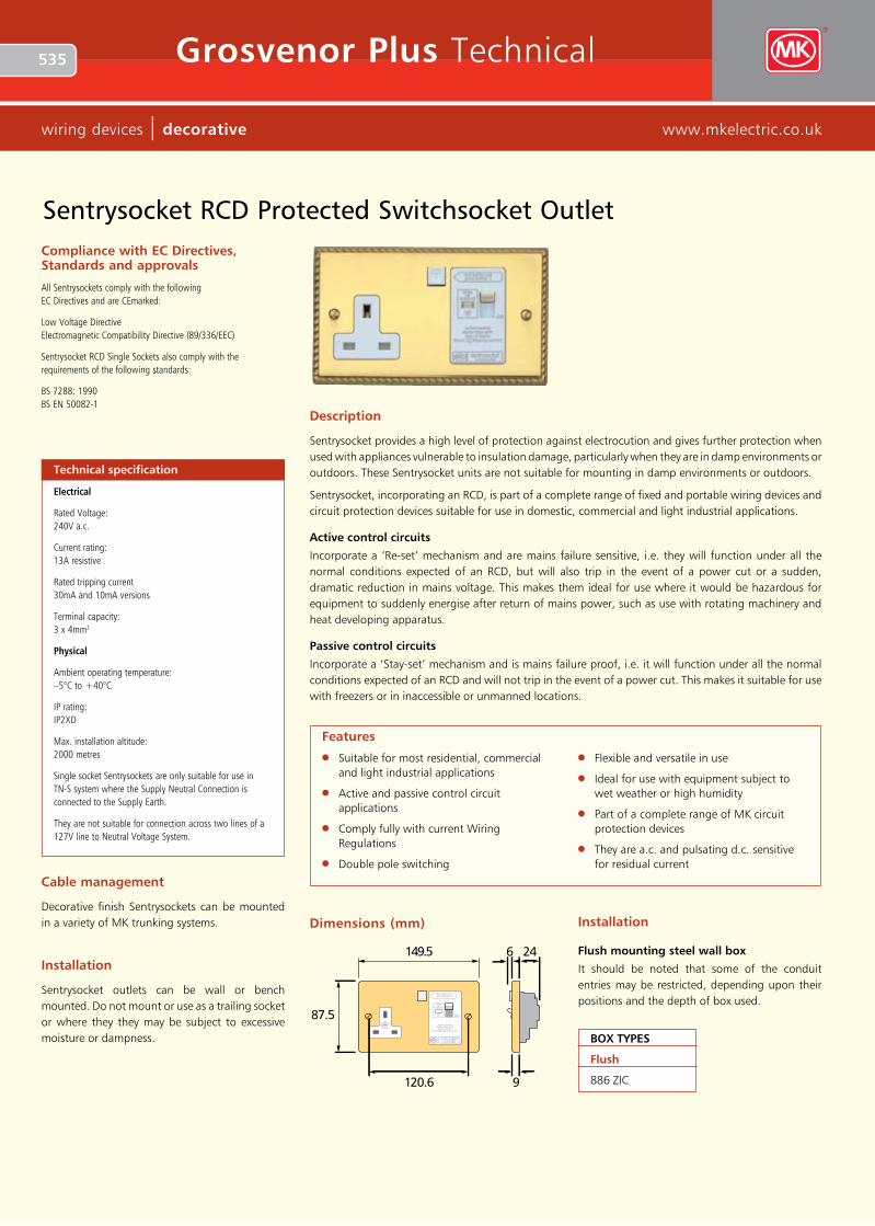
Sentrysocket provides a high level of protection against electrocution and gives further protection when used with appliances vulnerable to insulation damage, particularly when they are in damp environments or outdoors. These Sentrysocket units are not suitable for mounting in damp environments or outdoors.
Sentrysocket, incorporating an RCD, is part of a complete range of fixed and portable wiring devices and circuit protection devices suitable for use in domestic, commercial and light industrial applications.
Active control circuits
Incorporate a ‘Re-set’ mechanism and are mains failure sensitive, i.e. they will function under all the normal conditions expected of an RCD, but will also trip in the event of a power cut or a sudden, dramatic reduction in mains voltage. This makes them ideal for use where it would be hazardous for equipment to suddenly energise after return of mains power, such as use with rotating machinery and heat developing apparatus.
Passive control circuits
Incorporate a ‘Stay-set’ mechanism and is mains failure proof, i.e. it will function under all the normal conditions expected of an RCD and will not trip in the event of a power cut. This makes it suitable for use with freezers or in inaccessible or unmanned locations.
149.5 24
87.5
120.6 9
TT test before usepress button - T
whiteoff
(tripped)
redon on
active controldevice trips with
loss of mains10mA tripping current
6
sentrysocketrcd protected
Dimensions (mm) Installation
Flush mounting steel wall box
It should be noted that some of the conduit entries may be restricted, depending upon their positions and the depth of box used.
Compliance with eC Directives, Standards and approvals
All Sentrysockets comply with the following EC Directives and are CEmarked:
Low Voltage Directive Electromagnetic Compatibility Directive (89/336/EEC)
Sentrysocket RCD Single Sockets also comply with the requirements of the following standards:
BS 7288: 1990 BS EN 50082-1
Technical specification
Electrical
Rated Voltage: 240V a.c.
Current rating: 13A resistive
Rated tripping current 30mA and 10mA versions
Terminal capacity: 3 x 4mm2
Physical
Ambient operating temperature: –5°C to +40°C
IP rating: IP2XD
Max. installation altitude: 2000 metres
Single socket Sentrysockets are only suitable for use in TN-S system where the Supply Neutral Connection is connected to the Supply Earth.
They are not suitable for connection across two lines of a 127V line to Neutral Voltage System.
Cable management
Decorative finish Sentrysockets can be mounted in a variety of MK trunking systems.
Installation
Sentrysocket outlets can be wall or bench mounted. Do not mount or use as a trailing socket or where they they may be subject to excessive moisture or dampness.
Sentrysocket RCD Protected Switchsocket Outlet
Box TyPeS
Flush
886 ZIC

536
technical hotline +44 (0)1268 563720 decorative | wiring devices
Grosvenor Plus Technical
Round Pin Socket Outlets
Description
A range of round pin socket outlets designed for ease of installation and having all the advantages and design features of the Grosvenor Plus range. These products can be quickly installed as replace ments for existing socket outlets or in new installations.
l Top access terminals make wiring easier and quicker
l Integral ON indicator on switches will not rub off – totally safe
l 3mm minimum switch contact gap
l Double pole switching
l Terminal screws backed out
l Additional electrical safety from neutral “make first”, “break last” feature on switched sockets
l Switch contacts with silver contact points on both surfaces for good continuity
l 5A and 15A sockets contain a 3 pin operated safety shutter
l Printed terminal markings on grey rear mouldings for clearer identification
l 2A socket shuttered
Features
87.5
87.5
60.3
Depth2 Amp sockets: 12mm5 Amp sockets: 21mm15 Amp sockets: 23mm
9
Dimensions (mm)
Box TyPeS
Flush for extra Flush wiring space
5A and 15A 861 ZIC 866 ZIC
2A 3995 ZIC 866 ZIC 861 ZIC
Standards and approvals
Round pin socket outlets comply with BS 546: 1950.
Installation
Grosvenor Plus socket outlets can be wall or bench mounted – Do not mount or use as a trailing socket or where they may be subject to excessive moisture or dampness.
Technical specification
Electrical
Voltage rating: 250V a.c.
Terminal capacities: 2 amp sockets (K4380): 7 x 1mm2 4 x 1.5mm2 2 x 2.5mm2 1 x 4mm2 5 amp sockets (K4381): 3 x 2.5mm2 2 x 4mm2 2 x 6mm2 (stranded) 15 amp sockets (K4383): 3 x 2.5mm2 3 x 4mm2 2 x 6mm2 (stranded)
Physical
Ambient operating temperature: –5°C to +40°C (not to exceed an average of more than 25°C in any 24 hour period)
IP rating: IP2XD
Max. installation altitude: 2000 metres
Cable management
Grosvenor Plus socket outlets can be mounted in a variety of MK trunking systems.

537
wiring devices | decorative www.mkelectric.co.uk
Grosvenor Plus Technical
Standards and approvals
Complies with SASO 2203: 2003
Technical specification
15AAmerican
Electrical
Voltage rating: 127V a.c.
Current rating: 15A
Terminal capacity: Live, neutral & earth 3 x 2.5mm2 2 x 4mm2 1 x 6mm2 (stranded)
Physical
Ambient operating temperature: –5°C to +40°C (not to exceed an average of more than 25°C in any 24 hour period)
IP rating: IP2XD
Max. installation altitude: 2000 metres
87.5
87.5
60.3
149.5
87.5
120.6 15
9
Box TyPeS
Flush Flush for extra wiring space
1 gang 861 ZIC 866 ZIC
2 gang 862 ZIC 886 ZIC
15AAmerican Socket Outlet
Dimensions (mm)
Installation
Grosvenor Plus socket outlets can be wall or bench mounted. Do not mount or use as a trailing socket or where they they may be subject to excessive moisture or dampness.

538
technical hotline +44 (0)1268 563720 decorative | wiring devices
Grosvenor Plus Technical
Power Modules
Dimensions (mm)
Installation
MK socket outlets can be wall or bench mounted. Do not mount or use as a trailing socket or where they may be subject to excessive moisture or dampness.
16AGerman 15AAmerican13AUK
50
50
25
50
50
40
50
50
25
Description
A range of euro modules designed to provide a variety of power options.
Standards and approvals
K5830: BS 1363: Part 2: 1995
K5831: IEC 60884-1: 2002
K5832: SASO 2203: 2003
Box TyPeS
Minimum
25mm
extra wiring space
35mm
Box TyPeS
Minimum
25mm
extra wiring space
35mm
Box TyPeS
Minimum
25mm
extra wiring space
35mm
Box TyPeS
Minimum
46mm
Box TyPeS
Minimum
46mm
K5830
5AUK
50
50
29
K5833 K5831
16AFrench/Belgian
50
50
39
K5834 K5832
Technical specification
13AUK
Electrical
Voltage rating: 250V a.c.
Current rating: 13A
Terminal capacity: Live, neutral & earth 3 x 2.5mm2 3 x 4mm2 2 x 6mm2 (stranded)
Physical
Ambient operating temperature: –5°C to +40°C (not to exceed an average of more than 25°C in any 24 hour period)
IP rating: IP2XD
Max. installation altitude: 2000 metres
5AUK
Electrical
Voltage rating: 250V a.c.
Current rating: 5A
Terminal capacity: Live, neutral & earth 3 x 2.5mm2 2 x 4mm2 2 x 6mm2 (stranded)
Physical
Ambient operating temperature: –5°C to +40°C (not to exceed an average of more than 25°C in any 24 hour period)
IP rating: IP2XD
Max. installation altitude: 2000 metres
16AGerman
Electrical
Voltage rating: 250V a.c.
Current rating: 16A
Terminal capacity: Live, neutral & earth 4 x 1.5mm2 2 x 2.5mm2 1 x 4mm2
Physical
Ambient operating temperature: –5°C to +40°C (not to exceed an average of more than 25°C in any 24 hour period)
IP rating: IP2XD
Max. installation altitude: 2000 metres
16AFrench/Belgian
Electrical
Voltage rating: 250V a.c.
Current rating: 16A
Terminal capacity: Live, neutral & earth 3 x 2.5mm2 2 x 4mm2 1 x 6mm2
Physical
Ambient operating temperature: –5°C to +40°C (not to exceed an average of more than 25°C in any 24 hour period)
IP rating: IP2XD
Max. installation altitude: 2000 metres
15AAmerican
Electrical
Voltage rating: 127V a.c.
Current rating: 15A
Terminal capacity: Live, neutral & earth 3 x 2.5mm2 2 x 4mm2 1 x 6mm2 (stranded)
Physical
Ambient operating temperature: –5°C to +40°C (not to exceed an average of more than 25°C in any 24 hour period)
IP rating: IP2XD
Max. installation altitude: 2000 metres
K5833: BS 546: 1950
K5834: French National Standard NF C 61-314

539
wiring devices | decorative www.mkelectric.co.uk
Grosvenor Plus Technical
l Bottom access terminal screws make wiring quicker and easier
l Automatic primary supply switching on insertion of plug
l Choice of 230V or 115V output socket positions
l Safety interlocked shutters to prevent insertion of two plugs simultaneously
l Only one size of screwdriver required for installation
l Terminal screws supplied ‘backed out’ and held captive within the terminal moulding
l Printed terminal markings on grey rear mouldings for clearer identification
l Front plate fixing screws retained on rear case moulding
l Integral over current device to protect transformer
Features
Cable management
Decorative finish shaver supply units can be mounted in a variety of MK trunking systems.
Description
Designed for ease of installation and having many of the advantageous design features of the Grosvenor Plus range.
May be used in bathrooms and washrooms but must only be installed in accordance with the current IEE Wiring Regulations BS 7671: 1992: Amendment 3.
Installation
Shaver supply unit should be wall mounted.
Wiring
An installation instruction leaflet is available. List no. 44994 PL.
149.5
987.5
35
shaversonly
230V115V
Dimensions (mm)
Standards and approvals
Shaver supply units comply with BS EN 61558-2-5: 1998
Accommodates plugs as follows:
l British 5mm diameter pins on 16.6mm pitch (230V socket) to BS 4573: 1970.
l European 4mm diameter pins on 17 to 19mm pitch (230V socket) to IEC 83: 1975 Standard C5.
l Australian 6.5 x 1.6 flat blades each set at 30° to the vertical on a nominal pitch of 13.7mm (230V socket) AS C112: 1964.
l American 6.6 x 1.6 flat horizontal blades on 12.7mm pitch (115V socket) to ANSI C73.10.
Technical specification
Electrical
Voltage rating: K701: 230V a.c. Input (will operate at 220-250V a.c.) K706: 127V a.c. Input (will operate at 110-130V a.c.) 230V or 115V nominal outputs
Current rating: K701: 200mA max. (internal thermister trip current) K706: 400mA max. (internal thermister trip current)
Maximum load: 20VA No load voltage < 275V
Terminal capacities: Each terminal will accommodate 1 x 4mm2 or 2 x 2.5mm2 solid conductors*
Physical
Ambient operating temperature: –5°C to +40°C
IP rating: IP41 (In Zone 2 if fixed where direct spray from showers is unlikely)
Max. installation altitude: 2000 metres
*The design of this unit means that on no load the transformer output is allowed to be as high as 275V. This means that rechargeable shavers intended for use on the continent may be damaged by the inrush current created by this higher voltage. Rechargeable shavers with a wide range of input voltage should be recharged at 115V. Shavers manufactured for the UK are designed to be used with a transformer unit. Loads in excess of 20VA may cause the solid state overload to operate before shaving is completed. This is to protect the transformer.
Shaver Supply Units
Box TyPeS
Flush mounting only
Metal box 878 ZIC (minimum metal mounting box depth is 47mm)

540
technical hotline +44 (0)1268 563720 decorative | wiring devices
Grosvenor Plus Technical
Connection Units
l Optional indicators in the switch rockers with 175° visibility in the horizontal and vertical planes
l Worm-drive operated fuse carriers for additional security (tamper-proof version available)
l Fuse carrier lockable in open position
l All supply and load cables can be cut and stripped to the same length
l Integrally wired indicators save installation time
l Push-fit cord grips, for safer, quicker installation
l Angled, top mounted terminal screws simplify wiring
l Moulded ‘on’ indicator flash on switches cannot rub off – totally safe
l Captive fuse carrier
l Additional electrical safety from neutral ‘make first’, ‘break last’ feature
l Secure cable and flexible cord connection
l All terminal and fixing screws operated by one-size (4mm) screwdriver
l Backed out and captive terminal screws
Features
Description
A range of 13A fused connection units designed for the connection of refrigerators, water heaters, central heating boilers and other fixed appliances.
The range is designed for ease of instal la tion and have the advantageous design features of the Grosvenor Plus range.
Neon indicators
Neon indicators can be included in the rockers of the switched connection units. In the case of unswitched units, they are located centrally and uppermost on the face plate. Neon indicators are integrally wired into the product and do not require separate connection when installing.
The design gives 175° visibility in the horizon tal and vertical planes.
Fuse carriers
These are captive and are opened by a fast acting, screwdriver operated worm drive for ease of replacement.
Fuse carriers can be locked open using a padlock, List No. K2000.
Flex outlets
The products are equipped with very strong, push-fit nylon cord grips making installation safe, quick and easy.
Standards and approvals
All Decorative Finish connection units comply with BS 1363: Part 4: 1995.
The 20A DP switch complies with BS 3676: Part 1: 1989.
Fuses are to BS 1362
Technical specification
Electrical
Voltage rating: 250V a.c.
Current rating: 13 amp
Terminal capacity:
Supply terminal: 2 x 6mm2 stranded 2 x 4mm2 3 x 2.5mm2
Load terminals: 2 x 6mm2 stranded 2 x 4mm2 3 x 2.5mm2
Flex outlet/cord grip capacities: min: 2 core, 0.5mm
max: 3 core, 1.5mm
Physical
Ambient operating temperature: –5°C to +40°C (not to exceed an average of more than 25°C in any 24 hour period)
IP rating: With flex outlet: IP2XD Without flex outlet: IP4X
Max. installation altitude: 2000 metres
Cable management
Decorative finish connection units and DP switches can be mounted in a variety of MK trunking systems.
Box TyPeS
Flush
886 ZIC

541
wiring devices | decorative www.mkelectric.co.uk
Grosvenor Plus Technical
Dimensions (mm)
87.5 19
87.5
60.311 dia
fusefuse
9
Front outlet cord grip
Supply and load cable cords cut and stripped to same length.
Lockable fuse carrier
Installation
Decorative Finish connection units and 20A switches can be wall or bench mounted. Do not use on a trailing lead.
Wiring
Products must be installed in accordance with current IEE Regulations.
Connection Units
542
technical hotline +44 (0)1268 563720 decorative | wiring devices
Grosvenor Plus Technical
High Current Switches and Cooker Control Units
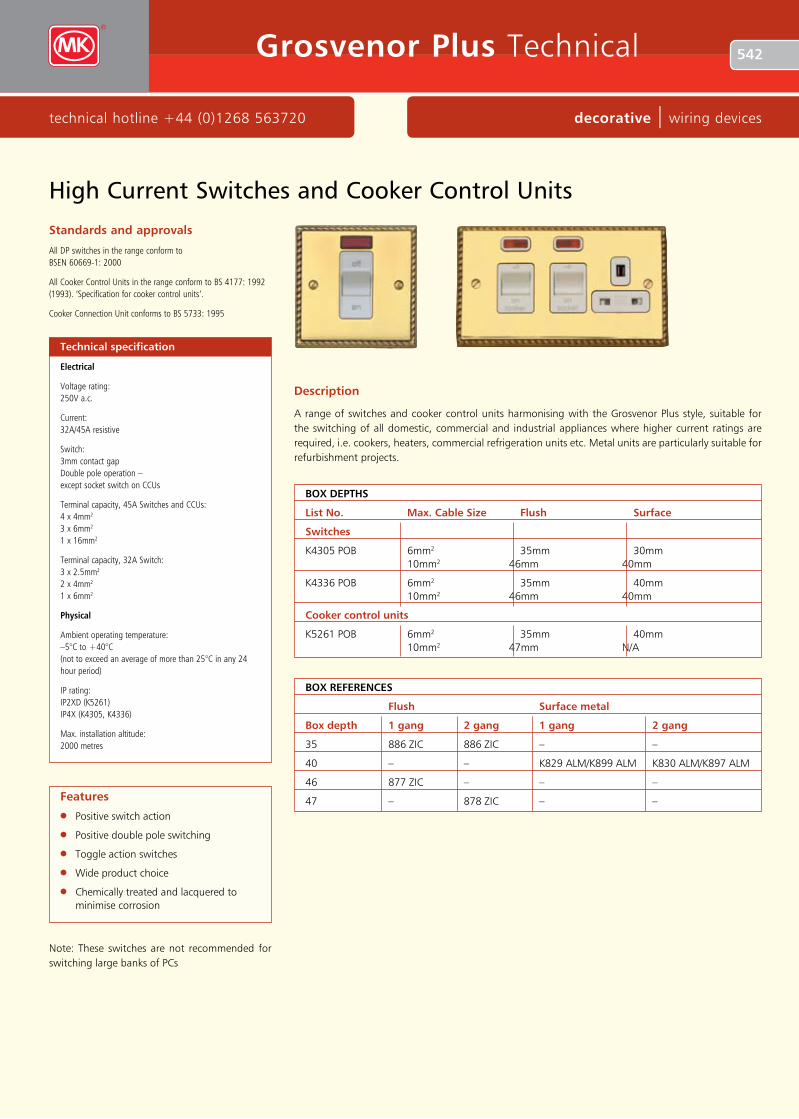
Description
A range of switches and cooker control units harmonising with the Grosvenor Plus style, suitable for the switching of all domestic, commercial and industrial appliances where higher current ratings are required, i.e. cookers, heaters, commercial refrigeration units etc. Metal units are particularly suitable for refurbishment projects.
Technical specification
Electrical
Voltage rating: 250V a.c.
Current: 32A/45A resistive
Switch: 3mm contact gap Double pole operation – except socket switch on CCUs
Terminal capacity, 45A Switches and CCUs: 4 x 4mm2 3 x 6mm2 1 x 16mm2
Terminal capacity, 32A Switch: 3 x 2.5mm2 2 x 4mm2 1 x 6mm2
Physical
Ambient operating temperature: –5°C to +40°C (not to exceed an average of more than 25°C in any 24 hour period)
IP rating: IP2XD (K5261) IP4X (K4305, K4336)
Max. installation altitude: 2000 metres
l Positive switch action
l Positive double pole switching
l Toggle action switches
l Wide product choice
l Chemically treated and lacquered to minimise corrosion
Features
Note: These switches are not recommended for switching large banks of PCs
Standards and approvals
All DP switches in the range conform to BSEN 60669-1: 2000
All Cooker Control Units in the range conform to BS 4177: 1992 (1993). ‘Specification for cooker control units’.
Cooker Connection Unit conforms to BS 5733: 1995
Box DePThS
List No. Max. Cable Size Flush Surface
Switches
K4305 POB 6mm2 35mm 30mm 10mm2 46mm 40mm
K4336 POB 6mm2 35mm 40mm 10mm2 46mm 40mm
Cooker control units
K5261 POB 6mm2 35mm 40mm 10mm2 47mm N/A
Box ReFeReNCeS
Flush Surface metal
Box depth 1 gang 2 gang 1 gang 2 gang
35 886 ZIC 886 ZIC – –
40 – – K829 ALM/K899 ALM K830 ALM/K897 ALM
46 877 ZIC – – –
47 – 878 ZIC – –

543
wiring devices | decorative www.mkelectric.co.uk
Grosvenor Plus Technical
High Current Switches and Cooker Control Units
87.5
87.5
60.3
off
on
12
20
149.5 120.6
87.5
off
on
19
20
Dimensions (mm)
149.5
120.6
off
on
off
onsocketcooker
87.5
13
20
K4305 K5261
K4336

544
technical hotline +44 (0)1268 563720 decorative | wiring devices
Grosvenor Plus Technical
Plateswitches
l Two way switches can be wired as one or two way
l All products clearly printed with BS Nos., ratings, etc
l Matching Grid switches available in 10 or 20A ratings
l 3mm switch contact gap
l Positive switch action
l Top access, backed out and captive terminal screws
l An earth terminal is provided attached to rear of product
Features
Description
Choice of white or black inserts, or black inserts with matching metal rocker switches.
Sectional drawings show the furthest projections from the back of the frontplate (wall surface).
Dimensions (mm)
1 gang 2 gang 3 gang
Standards and approvals
All Decorative Finish plateswitches comply with BS EN 60669-1: 2000
Technical specification
Electrical
Voltage rating: 250V a.c. 50Hz
Current rating: 10 amps – no derating when used on fluorescent or inductive loads
Switches can be wired as either one-way or two-way.
Terminal capacity: All products – 4 x 1mm2 4 x 1.5mm2 3 x 2.5mm2 2 x 4mm2 1 x 6mm2
Contact gap: 3mm switch contact gap
Physical
Operating temperature: –5°C to +40°C)
IP rating: IP4X
Max. installation altitude: 2000 metres
Operational testing (all plateswitches): tested to 100,000 operations for mechanical life tested to 30,000 operations at 10 amp rating
All plateswitches in this ranges are rated 10AX.
Cable management
Decorative finish plateswitches can be mounted in a variety of MK trunking systems.
87.5
87.5
60.3 12
7 87.5
87.5
60.3 12
7 87.5
87.5
60.3 12
7
87.5
87.5
60.3 12
7 87.5
87.5
60.3 12
7Box TyPeS
Flush
3995 ZIC
545
wiring devices | decorative www.mkelectric.co.uk
Grosvenor Plus Technical
Plateswitches
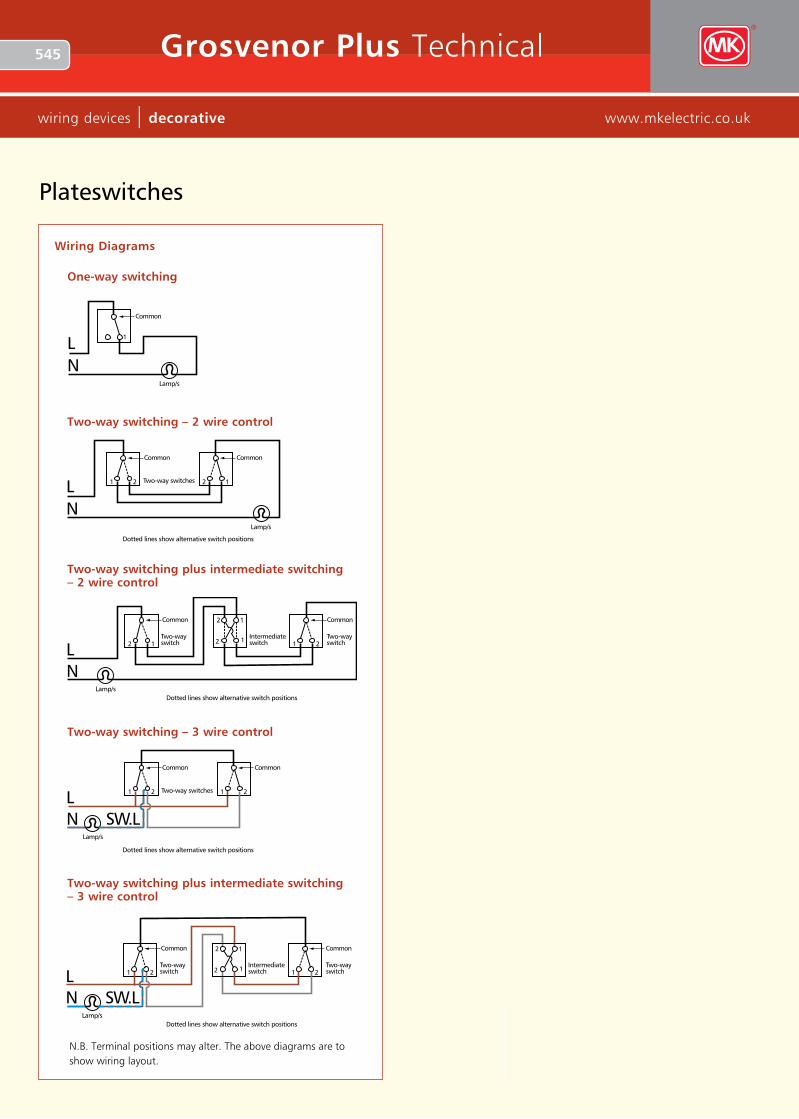
Wiring Diagrams
one-way switching
NL
One-way switching
1
Common
Lamp/s
NL
Two-way switching
Lamp/s
21
Common
12
Common
Two-way switches
Dotted lines show alternative switch positions
NL
Two-way switching3 wire control
21
Common
21
Common
Two-way switches
Dotted lines show alternative switch positions
Lamp/s
SW.L
L
NL
Two-way plusintermediate switching
12
Common
21
Common
Two-wayswitch
Two-wayswitch
Dotted lines show alternative switch positionsLamp/s
1
1
2
2
1
1
2
2
Intermediateswitch
Two-way plusintermediate switching3 wire control
21
Common
21
Common
Two-wayswitch
Two-wayswitch
Dotted lines show alternative switch positions
Intermediateswitch
NLamp/s
SW.L
Two-way switching – 2 wire control
NL
One-way switching
1
Common
Lamp/s
NL
Two-way switching
Lamp/s
21
Common
12
Common
Two-way switches
Dotted lines show alternative switch positions
NL
Two-way switching3 wire control
21
Common
21
Common
Two-way switches
Dotted lines show alternative switch positions
Lamp/s
SW.L
L
NL
Two-way plusintermediate switching
12
Common
21
Common
Two-wayswitch
Two-wayswitch
Dotted lines show alternative switch positionsLamp/s
1
1
2
2
1
1
2
2
Intermediateswitch
Two-way plusintermediate switching3 wire control
21
Common
21
Common
Two-wayswitch
Two-wayswitch
Dotted lines show alternative switch positions
Intermediateswitch
NLamp/s
SW.L
Two-way switching – 3 wire control
NL
One-way switching
1
Common
Lamp/s
NL
Two-way switching
Lamp/s
21
Common
12
Common
Two-way switches
Dotted lines show alternative switch positions
NL
Two-way switching3 wire control
21
Common
21
Common
Two-way switches
Dotted lines show alternative switch positions
Lamp/s
SW.L
L
NL
Two-way plusintermediate switching
12
Common
21
Common
Two-wayswitch
Two-wayswitch
Dotted lines show alternative switch positionsLamp/s
1
1
2
2
1
1
2
2
Intermediateswitch
Two-way plusintermediate switching3 wire control
21
Common
21
Common
Two-wayswitch
Two-wayswitch
Dotted lines show alternative switch positions
Intermediateswitch
NLamp/s
SW.L
Two-way switching plus intermediate switching – 2 wire control
NL
One-way switching
1
Common
Lamp/s
NL
Two-way switching
Lamp/s
21
Common
12
Common
Two-way switches
Dotted lines show alternative switch positions
NL
Two-way switching3 wire control
21
Common
21
Common
Two-way switches
Dotted lines show alternative switch positions
Lamp/s
SW.L
L
NL
Two-way plusintermediate switching
12
Common
21
Common
Two-wayswitch
Two-wayswitch
Dotted lines show alternative switch positionsLamp/s
1
1
2
2
1
1
2
2
Intermediateswitch
Two-way plusintermediate switching3 wire control
21
Common
21
Common
Two-wayswitch
Two-wayswitch
Dotted lines show alternative switch positions
Intermediateswitch
NLamp/s
SW.L
Two-way switching plus intermediate switching – 3 wire control
NL
One-way switching
1
Common
Lamp/s
NL
Two-way switching
Lamp/s
21
Common
12
Common
Two-way switches
Dotted lines show alternative switch positions
NL
Two-way switching3 wire control
21
Common
21
Common
Two-way switches
Dotted lines show alternative switch positions
Lamp/s
SW.L
L
NL
Two-way plusintermediate switching
12
Common
21
Common
Two-wayswitch
Two-wayswitch
Dotted lines show alternative switch positionsLamp/s
1
1
2
2
1
1
2
2
Intermediateswitch
Two-way plusintermediate switching3 wire control
21
Common
21
Common
Two-wayswitch
Two-wayswitch
Dotted lines show alternative switch positions
Intermediateswitch
NLamp/s
SW.L
N.B. Terminal positions may alter. The above diagrams are to show wiring layout.
546
technical hotline +44 (0)1268 563720 decorative | wiring devices
Grosvenor Plus Technical
Dimmer SwitchesStandards and approvals
All CE marked Decorative finishes dimmer switches comply with the EC Low Voltage Directive: 73/23/EEC, Electromagnetic Compatibility Directive 89/336/EEC
They also comply with BS EN 60669-2-1 and BS EN 55015
Non-UKdimmer switches conform to the relevant parts of BS 5518.
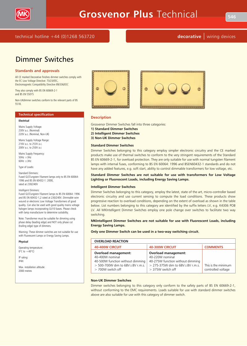
Description
Grosvenor Dimmer Switches fall into three categories: 1) Standard Dimmer Switches 2) Intelligent Dimmer Switches 3) Non-UK Dimmer Switches
Standard Dimmer Switches
Dimmer Switches belonging to this category employ simpler electronic circuitry and the CE marked products make use of thermal switches to conform to the very stringent requirements of the Standard BS EN 60669-2-1, for overload protection. They are only suitable for use with normal tungsten filament lamps with internal fuses, conforming to BS EN 60064: 1996 and BSEN60432-1 standards and do not have any added features, e.g. soft start, ability to control dimmable transformers for low voltage, etc.
Standard Dimmer Switches are not suitable for use with transformers for Low Voltage Lighting or Fluorescent Loads, including energy Saving Lamps.
Intelligent Dimmer Switches
Dimmer Switches belonging to this category, employ the latest, state of the art, micro-controller based electronic circuitry and use current sensing to compute the load conditions. These products show progressive reaction to overload conditions, depending on the extent of overload as shown in the table below. List numbers belonging to this category are identified by the suffix letters LV, e.g. K4306 POB LV. All MKIntelligent Dimmer Switches employ one pole change over switches to facilitate two way switching.
MKIntelligent Dimmer Switches are not suitable for use with Fluorescent Loads, including energy Saving Lamps.
only one Dimmer Switch can be used in a two-way switching circuit.
Technical specification
Electrical
Mains Supply Voltage: 230V a.c. (Nominal) 220V a.c. (Nominal, Non-UK)
Mains Supply Voltage Range: 216V a.c. to 253V a.c. 200V a.c. to 250V a.c
Mains Supply Frequency: 50Hz ±3Hz 60Hz ±3Hz
Type of Loads:
Standard Dimmers: Fused GLSTungsten Filament lamps only to BS EN 60064: 1996 and BS EN 60432-1: 2000, rated at 230/240V
Intelligent Dimmers: Fused GLSTungsten Filament lamps to BS EN 60064: 1996 and BS EN 60432-1,2 rated at 230/240V. Dimmable wire wound or electronic Low Voltage Transformers of good quality. Can also be used with good quality mains voltage halogen lamps incorporating GU10 bases. Please check with lamp manufacturer to determine suitability.
Note: Transformer must be suitable for dimming using phase delay (leading edge) and NOT only phase cut (trailing edge) type of dimmers.
Warning: These dimmer switches are not suitable for use with Fluorescent Lamps or Energy Saving Lamps.
Physical
Operating temperature: 0°C to +40°C)
IP rating: IP4X
Max. installation altitude: 2000 metres
Non-UK Dimmer Switches
Dimmer switches belonging to this category only conform to the safety parts of BS EN 60669-2-1, without conforming to the EMC requirements. Loads suitable for use with standard dimmer switches above are also suitable for use with this category of dimmer switch.
oVeRLoAD ReACTIoN
40-400W CIRCUIT 40-300W CIRCUIT CoMMeNTS
overload management: overload management: 40-400W nominal 40-220W nominal 40-500W function without dimming 40-275W function without dimming > 500-700W dim to 68V±8V r.m.s. > 275-375W dim to 68V±8V r.m.s. This is the minimum > 700W switch off > 375W switch off controlled voltage

547
wiring devices | decorative www.mkelectric.co.uk
Grosvenor Plus Technical
Dimmer Switches
Intelligent Dimmer Switches incorporate the following advanced features
l Suitable for dimming Low Voltage Halogen lamps via good quality, fully dimmable electronic or wire-wound transformers
l Can be used with good quality mains voltage halogen lamps incorporating GU10 bases. Please check with lamp manufacturer to determine suitability
l Load current sensing: These dimmers continuously monitor the load current to help protect against overheating in wire wound transformers and to prevent overloading of the dimmer for long term reliability.
l Soft Start, which gradually increases the light output from the load over 1 to 3 seconds after switch on. The Soft Start feature is also particularly beneficial when used to dim Mains Voltage Tungsten Halogen lamps which have inherent very high inrush current at switch on
Standard Dimmer Switches
l Suitable only for use with fused GLS Tungsten Filament lamps to BSEN 60064 and BS EN 60432-1
l One way dimmer switches incorporate manual soft start
l Incorporate thermal switches for protection against overload
Features
N
L
L1
L2
C
Two-way switching(only one dimmer can be used)
L1
L2
C
LoadDIMMERSupply 230V a.c. - 50Hz
2 way switch
L
N
One-way switching
L1
L2
CLoad
DIMMERSupply 230V a.c. - 50Hz
Wires must be connected to the correct dimmer terminals.DO NOT connect earth to dimmer.
L
N
Fluorescent dimmer
1
2 HF FluorescentBallast
3
+
–
Wires must be connected to the correct dimmer terminals.DO NOT connect earth to dimmer.
1-10VDIMMINGCONTROLLER
Dimensions (mm)
1 gang single
87.5 24
60.3 18
87.5
87.5 24
60.3 21
87.5
149.5 24
120.6 18
87.5
2 gang triple
Box TyPeS
Flush Surface
1 gang (excluding double dimmers) 861 ZIC (25mm) –
1 gang (for double dimmers) 866 ZIC (35mm) –
2 gang 862 ZIC (25mm) –
1 gang switches (Albany MCOonly) – K829 ALM/K899 ALM
2 gang switches (Albany MCOonly) – K830 ALM/897 ALM
1 gang double
Please note the dimmer may be substituted for any of the Two-Way switches
INTeLLIGeNT DIMMeR SWITCheS
Rating Max No. of Transformers (total rating of all transformers must not exceed maximum VA rating of dimmer)
1 gang single 40-300W (LV and mains voltage 4 dimmer halogen rating 40-240W/VA)
1 gang double 2 x 40-300W (LV and mains voltage 4 per dimmer dimmer halogen rating 2 x 40-240W/VA)
1 gang single 60-500W (LV and mains voltage 5 dimmer halogen 60-400W/VA)
548
technical hotline +44 (0)1268 563720 decorative | wiring devices
Grosvenor Plus Technical
Standards and approvals
Grosvenor Plus TV sockets comply with the following:
TV sockets K3520, K3521 and K3523
BS 3041: Part 2: 1977/IEC 169-2: 1977, BS5733: 1995 (where applicable) and IEC65, Cls 10.1, 10.3.
TV sockets K3525
BS 5733: 1995 (where applicable).
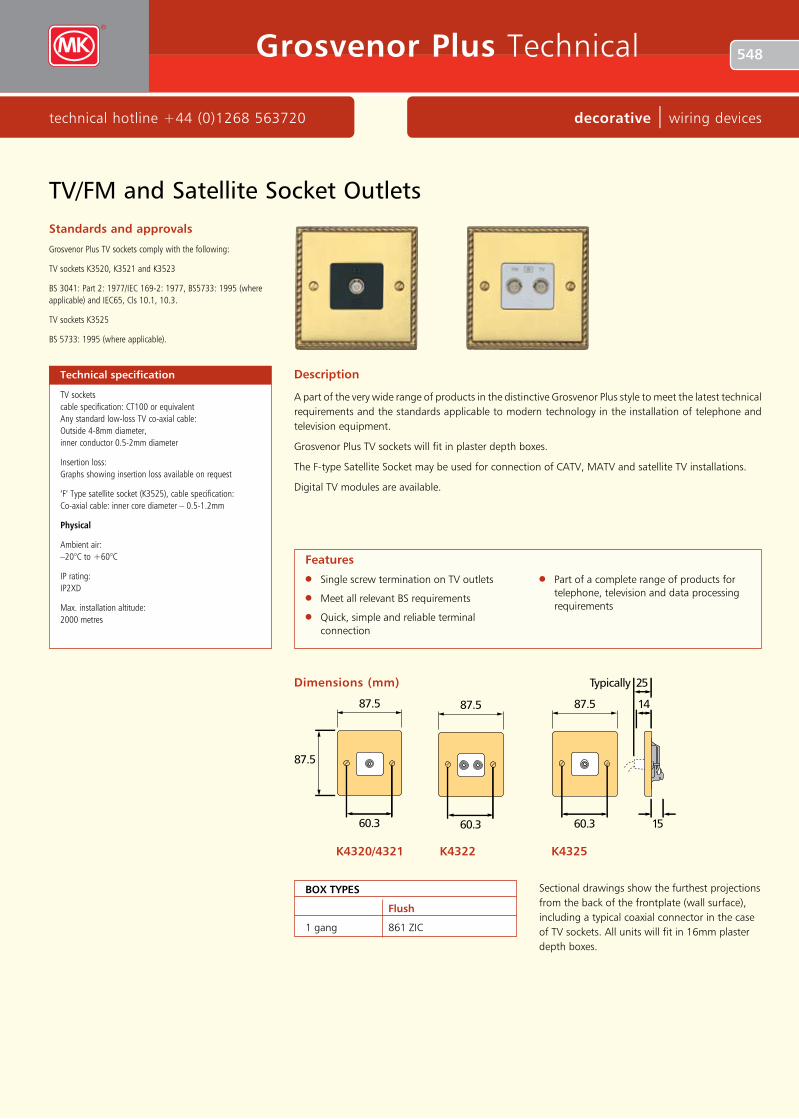
Description
A part of the very wide range of products in the distinctive Grosvenor Plus style to meet the latest technical requirements and the standards applicable to modern technology in the installation of telephone and television equipment.
Grosvenor Plus TV sockets will fit in plaster depth boxes.
The F-type Satellite Socket may be used for connection of CATV, MATV and satellite TV installations.
Digital TV modules are available.
Technical specification
TV sockets cable specification: CT100 or equivalent Any standard low-loss TV co-axial cable: Outside 4-8mm diameter, inner conductor 0.5-2mm diameter
Insertion loss: Graphs showing insertion loss available on request
‘F’ Type satellite socket (K3525), cable specification: Co-axial cable: inner core diameter – 0.5-1.2mm
Physical
Ambient air: –20°C to +60°C
IP rating: IP2XD
Max. installation altitude: 2000 metres
l Single screw termination on TV outlets
l Meet all relevant BS requirements
l Quick, simple and reliable terminal connection
l Part of a complete range of products for telephone, television and data processing requirements
Features
TV/FM and Satellite Socket Outlets
87.5 14
25Typically
87.5
60.3 15
87.5 14
25Typically
87.5
60.3 15
K4320/4321
87.5 14
25Typically
87.5
60.3 15
K4325 K4322
Dimensions (mm)
Sectional drawings show the furthest projections from the back of the frontplate (wall surface), including a typical coaxial connector in the case of TV sockets. All units will fit in 16mm plaster depth boxes.
Box TyPeS
Flush
1 gang 861 ZIC

549
wiring devices | decorative www.mkelectric.co.uk
Grosvenor Plus Technical
Installation (TV sockets)
Product performance, systems compatibility
Isolated Outlets are intended for use where safety isolation (rated at 2000V a.c.) is required to provide protection against faults occurring within any mains powered product used on different parts of the distribution system. They are not suitable for use in systems where DC signals are passed through the socket, (e.g. where masthead/headend equipment is controlled by receiver/decoder equipment).
Diplexer Outlets are used in distribution systems where both TV and FM band signals are combined on a single aerial downlead. The filtering in the diplexer separates the appropriate signals and feeds them through to the relevant output connection port.
Cable Routing and Use of Cable Clamp
Sharp bends in the cable must be avoided during installation. The single TV/FM socket is fitted with a cable clamp that can be fixed on either side of the termination position to facilitate this.
When tightening the screening braid clamps ensure that the cable is firmly gripped and that the inner insulation is not squashed flat beyond a slight oval shape.
Safety Information
TV outlets or modules must not be installed in the same enclosure as equipment rated in excess of 50V, (e.g. mains rated 13A sockets or switches).
FM TV
TV
TVTV
TV
VID
VID
TV DIST
HI-FI
1
33
3 3
2
TV/FM and Satellite Socket Outlets
Method of installation of TV and FM aerial connection by using MK co-axial socket outlet and only one down lead.
Conventional distribution system for TV and FM signals using a single aerial downlead.
A standard TV/FM diplexer product is required to combine the TV and FM signals from the separate aerials in the loft space. (Black lines in wiring diagram).
The single cable feed from the diplexer then feeds to the input of a multi way distribution amplifier, typically located in the loft or garage. (Red line in wiring diagram).
Each individual output from the distribution amplifier is then fed to the individual rooms in the house to a standard TV (single or diplexer) outlet to which the TV/VCR and/or Hi-Fi can be connected. (Blue lines in wiring diagram).
1
2
3

550
technical hotline +44 (0)1268 563720 decorative | wiring devices
Grosvenor Plus Technical
Euro and LJU6C Data Frontplates
l 1G and 2G frontplates
l Grosvenor Plus style
l Accept industry standard Euro or LJU6C snapfit modules
l 1G Euro frontplate accepts 2 Euro modules, (50 x 50mm aperture)
l 2G Euro frontplate accepts 4 Euro modules, (100 x 50mm aperture)
l 2G LJU6C frontplate accepts two LJU6C modules (27 x 37mm aperture)
l 1⁄2 module (12.5 x 50mm) blank available for Euro frontplates
l Interchangeable modules clip into frontplate
Features
Standards and approvals
BS 5733: 1995
Technical specification
Dimensions
Height: 87.5mm
Width: 87.5mm (1G)
149.5mm (2G)
Depth: 9mm
Aperture Dimensions (Nominal)
Euro Frontplates
Height: 50mm
Width: 50mm (1G)
100mm (2G)
LJU6C Frontplates
Height: 37mm
Width: 22mm
Description
Frontplates used for mounting snapfit data modules.
Dimensions (mm)
euro Frontplates
87.5 9
87.5
60.3
1 gang K182 PoB
87.5 9
87.5
60.3
LJU6C Frontplates K172 PoB
149.5 9
87.5
120.6
2 gang K184 PoB

551
wiring devices | decorative www.mkelectric.co.uk
Grosvenor Plus Technical
87.5
87.5
60.3
149.5
87.5
120.6
87.5
87.5
60.3
149.5
87.5
120.6
Dimensions
1 module K4091 PoB
3 module K4093 PoB
2 module K4092 PoB
4 module K4094 PoB
Standards and approvals
BS.5733: 1995
Description
A unique modular system in the distinctive Grosvenor Plus style comprising a range of socket modules for Data and Telephone use, with 4 matching frontplates capable of accepting combinations of interchangeable modules. Modules clip into mounting frames which, when attached to frontplates, provide a high degree of versatility, making the system ideal for use in all commercial, industrial and domestic applications.
Technical specification
Physical
Temperature range: Ambient air –20°C to +60°C
IP rating: IP2XD
Max. installation altitude: 2000 metres
l Meet all relevant BS, OFTEL and cabling standards
l Interchangeable modules clip into grid frame which attaches to frontplate
l Front fixing facilitates easy exchange of modules
l Part of a range of products for telephone and data processing requirements
Features
MK Modular Data Frontplates

552
technical hotline +44 (0)1268 563720 decorative | wiring devices
Grosvenor Plus Technical
Grid Plus Front Plates
Dimensions
Standards and approvals
BS 5733: 1995
Description
Grid Plus is a comprehensive modular switching and monitoring system ideal for a variety of applications within the commercial, public and domestic sectors.
1 module K4331 PoB
2 module K4332 PoB
3 module K4333 PoB
4 module K4334 PoB
6 module K4336 PoB
12 module K4352 PoB
87.5
87.5
87.5
87.5
149.5
87.5
149.5
87.5
149.5
149.5
149.5
149.5
149.5
208
8 module K4338 PoB