Grosslab Jr
100
PSS # xxxx-xxx-xxx OP – GrossLab Jr. Model Numbers = TQC (Touch Quality Control) = CTQ (Critical to Quality)
-
Upload
john-williams -
Category
Documents
-
view
193 -
download
1
Transcript of Grosslab Jr
0
REV. ECN NO. DATE BY APPD. DESCRIPTION OF REVISION TOTAL #OF PAGES
PSS # xxxx-xxx-xxxOP – GrossLab Jr.
Model Numbers
= TQC (Touch Quality Control) = CTQ (Critical to Quality)
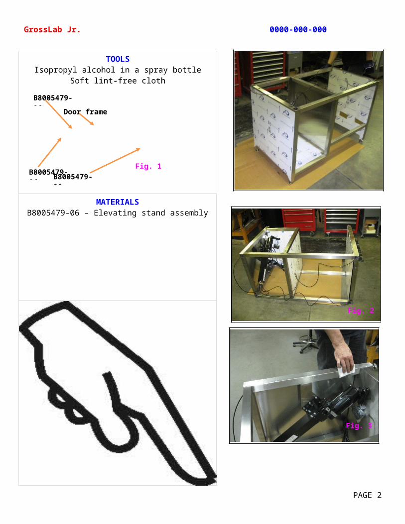
MATERIALSB8005479-06 – Elevating stand assembly
TOOLSIsopropyl alcohol in a spray bottle
Soft lint-free cloth
GrossLab Jr. 0000-000-000
PAGE 2
Fig. 1B8005479-06B8005479-06
B8005479-06
Door frame
Fig. 3
Fig. 2
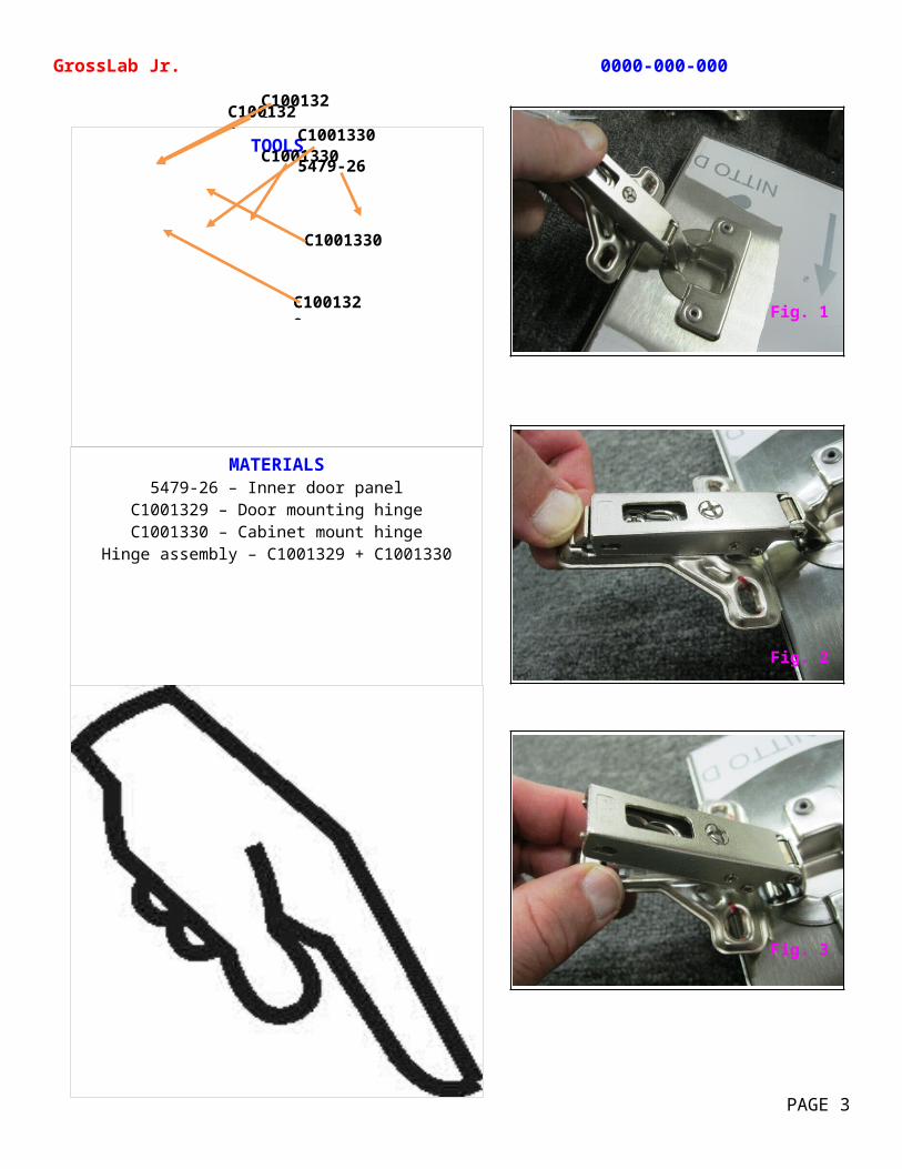
MATERIALS5479-26 – Inner door panel
C1001329 – Door mounting hingeC1001330 – Cabinet mount hinge
Hinge assembly – C1001329 + C1001330
TOOLS
GrossLab Jr. 0000-000-000
PAGE 3
5479-26
C1001329
C1001330
C1001330C1001330
C1001329C1001329
Fig. 1
Fig. 2
Fig. 3
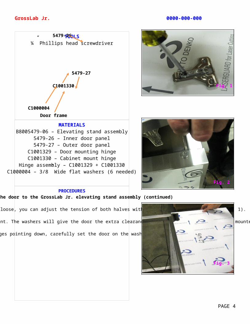
MATERIALSB8005479-06 – Elevating stand assembly
5479-26 – Inner door panel5479-27 – Outer door panel
C1001329 – Door mounting hingeC1001330 – Cabinet mount hinge
Hinge assembly – C1001329 + C1001330C1000004 – 3/8” Wide flat washers (6 needed)
PROCEDURESAttaching the door to the GrossLab Jr. elevating stand assembly (continued)
If the hinge seems to be too tight or loose, you can adjust the tension of both halves with a Phillips head screwdriver (Fig. 1).
Using washers as a spacer, stack 3 washers on each end of the door frame where the hinges mount. The washers will give the door the extra clearance it will need to open fully when mounted without causing undo strain on the hinges (Fig. 2).
With the hinges pointing down, carefully set the door on the washers (Fig. 3).
TOOLS¼” Phillips head screwdriver
GrossLab Jr. 0000-000-000
PAGE 4
5479-26
C1001330
C1000004Door frame
5479-27
Fig. 1
Fig. 3
Fig. 2
MATERIALSB8005479-06 – Elevating stand assembly
C1001329 – Door mounting hingeC1001330 – Cabinet mount hinge
Hinge assembly – C1001329 + C1001330C1000004 – 3/8” Wide flat washers (6 needed)
PROCEDURESAttaching the door to the GrossLab Jr. elevating stand assembly (continued)
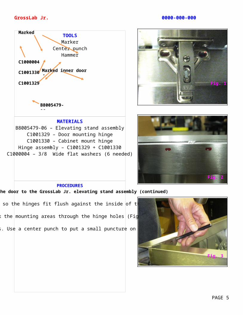
Position the door so the hinges fit flush against the inside of the frame (Fig. 1).
Mark the mounting areas through the hinge holes (Fig 2).
Remove the door and washers. Use a center punch to put a small puncture on the marked areas (Fig. 3).
TOOLSMarker
Center punchHammer
GrossLab Jr. 0000-000-000
PAGE 5
C1000004
C1001329
C1001330Marked inner door frame
Marked area
B8005479-06
Fig. 1
Fig. 3
Fig. 2
MATERIALSB8005479-06 – Elevating stand assembly
5479-26 – Inner door panelC1001329 – Door mounting hingeC1001330 – Cabinet mount hinge
Hinge assembly – C1001329 + C1001330107056 – 1/8 x 1/8 pop rivet
PROCEDURESAttaching the door to the GrossLab Jr. elevating stand assembly (continued)
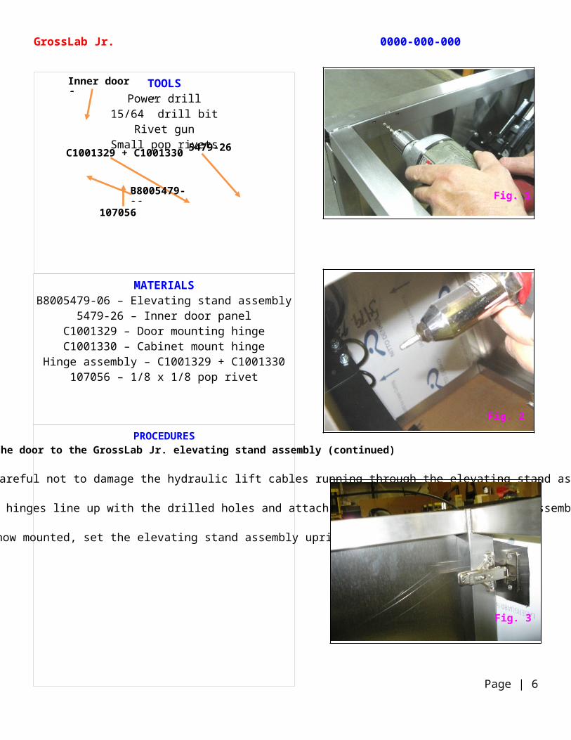
Drill 4 holes in the marked areas on the frame. Be careful not to damage the hydraulic lift cables running through the elevating stand assembly (Fig. 1).
Reposition the door, with washers in place, so the hinges line up with the drilled holes and attach the rivets through the hinge assemblies (Fig. 2).
With the door now mounted, set the elevating stand assembly upright (Fig. 3).
TOOLSPower drill
15/64” drill bitRivet gun
Small pop rivets
GrossLab Jr. 0000-000-000
Page | 6
C1001329 + C1001330 5479-26
Inner door frame
107056B8005479-06
Fig. 1
Fig. 3
Fig. 2
MATERIALSB8005479-06 – Elevating stand assembly
B1001089 – Hydraulic lift systemWooden base of packing crate
PROCEDURESTesting the hydraulic lift on the GrossLab Jr.
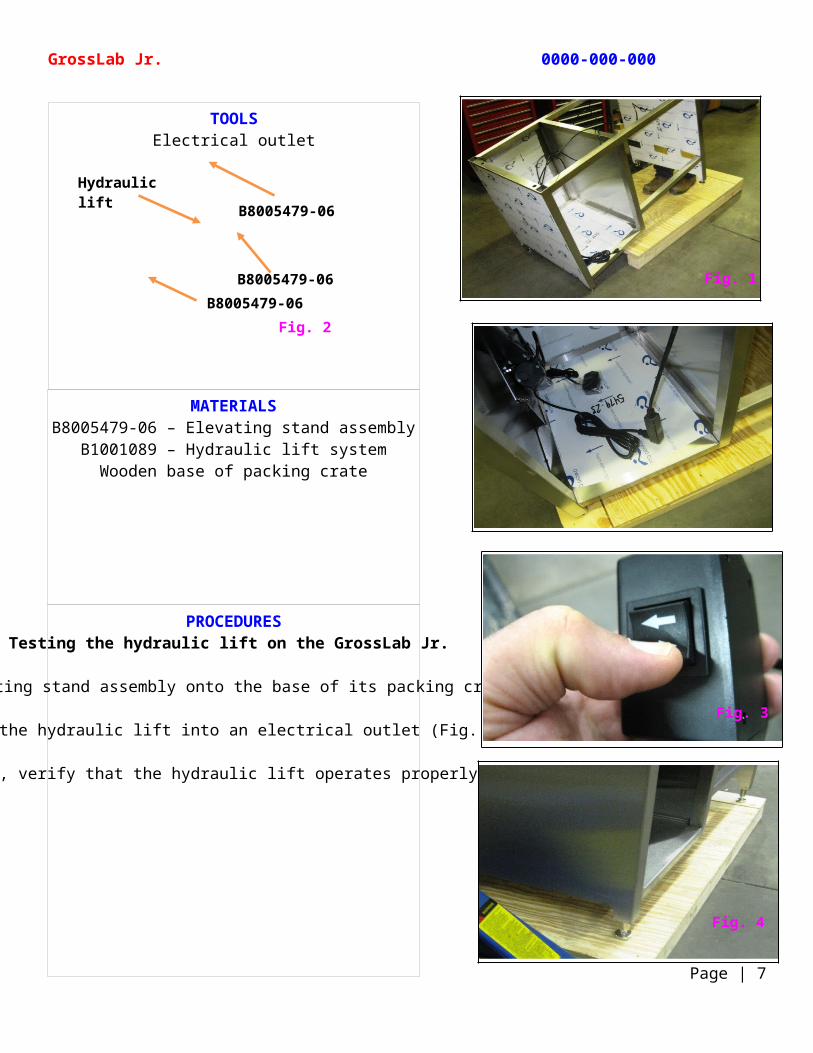
Lift the elevating stand assembly onto the base of its packing crate (Fig. 1).
Plug the hydraulic lift into an electrical outlet (Fig. 2).
Using the lift control, verify that the hydraulic lift operates properly (Fig. 3 and Fig. 4).
TOOLSElectrical outlet
GrossLab Jr. 0000-000-000
Page | 7
Fig. 2
B8005479-06
B8005479-06
Hydraulic lift control
B8005479-06Fig. 1
Fig. 3
Fig. 4
MATERIALSB10011 – Stainless steel sink
21200-72068 – 2” painters tapeDrain hole plug (optional)
Length of cardboard with sink basin cut out
PROCEDURESPainting the bottom of the stainless steel sink basin on the GrossLab Jr.
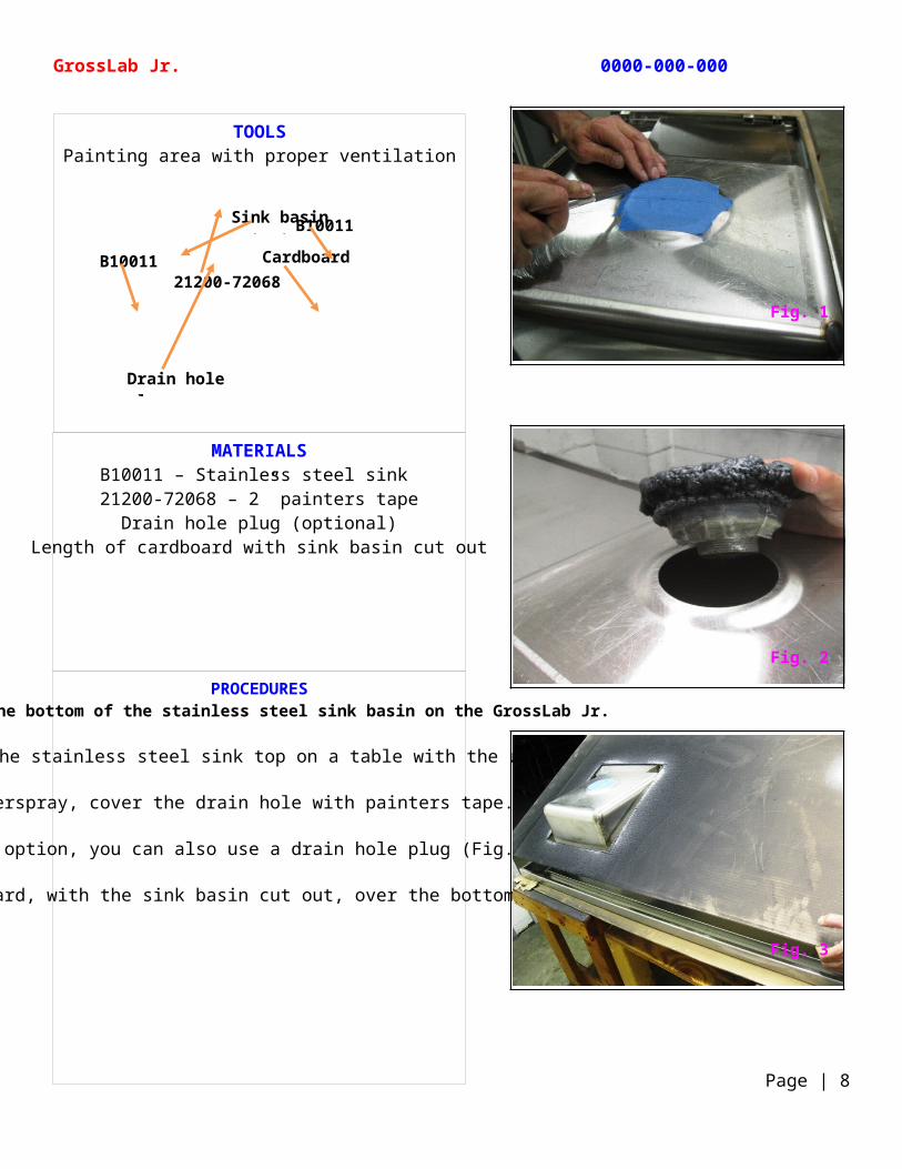
Gently set the stainless steel sink top on a table with the underside up.
To protect the sink top from overspray, cover the drain hole with painters tape. Trim any excess tape (Fig. 1).
As a option, you can also use a drain hole plug (Fig. 2).
Set a length of cardboard, with the sink basin cut out, over the bottom of the sink (Fig. 3).
TOOLSPainting area with proper ventilation
GrossLab Jr. 0000-000-000
Page | 8
21200-72068
B10011
Drain hole plug
B10011 Cardboard
Sink basin cutout
Fig. 1
Fig. 3
Fig. 2
MATERIALSB10011 – Stainless steel sink
51131-08882-5 – Undercoating 1686830 – Grey enamel spray paint
21200-72068 – 2” painters tape
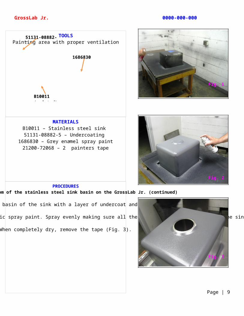
PROCEDURESPainting the bottom of the stainless steel sink basin on the GrossLab Jr. (continued)
Evenly cover the bottom basin of the sink with a layer of undercoat and let air dry (Fig 1).
Once the sink is dry, cover the undercoating with a metallic spray paint. Spray evenly making sure all the exposed area is covered. Let the sink air dry (Fig. 2).
When completely dry, remove the tape (Fig. 3).
TOOLSPainting area with proper ventilation
GrossLab Jr. 0000-000-000
Page | 9
51131-08882-5
1686830
B10011 (painted)Fig. 1
Fig. 3
Fig. 2

MATERIALSB8005479-06 – Elevating stand assembly
B8005479-09 – Inner side panel1075501 – #10-32 x 0.5, Phillips pan head screw
TOOLS#10-32 x 0.5 Phillips pan head screwdriver
GrossLab Jr. 0000-000-000
Page | 10
Fig. 2Fig. 3Fig. 4
B8005479-09
B8005479-09
B8005479-09
B8005479-09
B8005479-06B8005479-06
Fig. 1
MATERIALSB8005479-06 – Elevating stand assembly
B10011 – Stainless steel sink105505 – Hex head bolt, 3/8-16 x 2.0
C1000004 – 3/8” wide flat washer
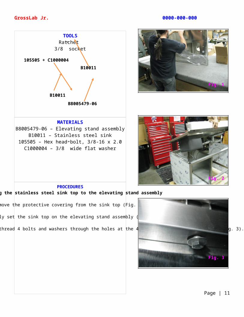
PROCEDURESAttaching the stainless steel sink top to the elevating stand assembly
Remove the protective covering from the sink top (Fig. 1).
Carefully set the sink top on the elevating stand assembly (Fig. 2).
Working from the underside of the sink, thread 4 bolts and washers through the holes at the 4 corners of the stand assembly (Fig. 3).
TOOLSRatchet
3/8” socket
GrossLab Jr. 0000-000-000
Page | 11
B10011
B10011
B8005479-06
105505 + C1000004
Fig. 1
Fig. 3
Fig. 2
MATERIALSB8005479-06 – Elevating stand assembly
B10011– Stainless steel sink105505 – Hex head bolt, 3/8-16 x 2.0
C1000004 – 3/8” wide flat washer1001691 – Plug
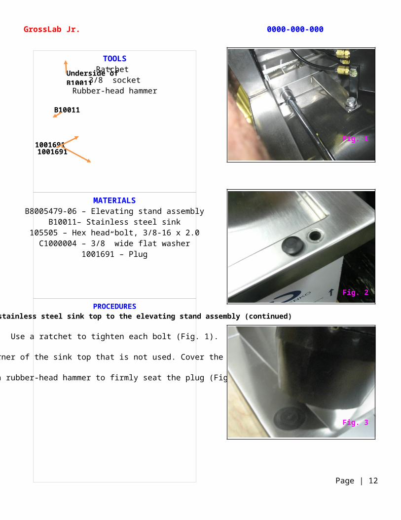
PROCEDURESAttaching the stainless steel sink top to the elevating stand assembly (continued)
Use a ratchet to tighten each bolt (Fig. 1).
There is a hole at the corner of the sink top that is not used. Cover the hole with a plug (Fig. 2).
Use a rubber-head hammer to firmly seat the plug (Fig. 3).
TOOLSRatchet
3/8” socketRubber-head hammer
GrossLab Jr. 0000-000-000
Page | 12
B10011
10016911001691
Underside of B10011
Fig. 1
Fig. 3
Fig. 2
MATERIALSB10011– Stainless steel sink
B8005479-02 – Left inside panel108355 – Phillips pan head screw, #8-32 x .375
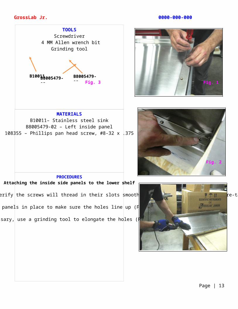
PROCEDURESAttaching the inside side panels to the lower shelf
Before you attach the inside panels to the lower shelf, verify the screws will thread in their slots smoothly and not bind. If necessary, re-tap the holes (Fig. 1).
Set the panels in place to make sure the holes line up (Fig. 2).
If necessary, use a grinding tool to elongate the holes (Fig. 3).
TOOLSScrewdriver
4 MM Allen wrench bitGrinding tool
GrossLab Jr. 0000-000-000
Page | 13
B10011B8005479-02Fig. 3
B8005479-02Fig. 1
Fig. 2
MATERIALSB8005479-02 – Left inside panel
10645 – Right inside panelB10012 – Lower shelf
108355 – Phillips pan head screw, #8-32 x .375
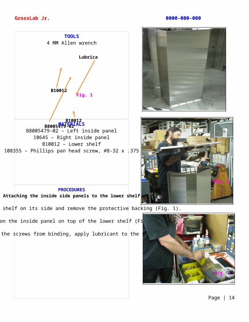
PROCEDURESAttaching the inside side panels to the lower shelf
Set the lower shelf on its side and remove the protective backing (Fig. 1).
Position the inside panel on top of the lower shelf (Fig. 2).
To help prevent the screws from binding, apply lubricant to the screws (Fig. 3).
TOOLS4 MM Allen wrench
GrossLab Jr. 0000-000-000
Page | 14
Fig. 1B10012
B10012B8005479-02
Lubricant
Fig. 3
Fig. 2
MATERIALSB8005479-02 – Left inside panel
10645 – Right inside panelB10012 – Lower shelf
1001152 – M6-1.0 x 10 button head socket
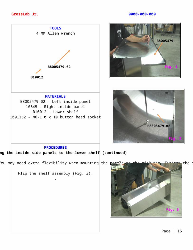
PROCEDURESAttaching the inside side panels to the lower shelf (continued)
Thread the screws into the side panel and tighten. Do not tighten the screws all the way at this point. You may need extra flexibility when mounting the panels to the sink top. Tighten the screws just enough to keep the assembly together (Fig. 1 and Fig. 2).
Flip the shelf assembly (Fig. 3)..
TOOLS4 MM Allen wrench
GrossLab Jr. 0000-000-000
Page | 15
B8005479-02
B10012
Fig. 1
B8005479-02
Fig. 3
B8005479-02
Fig. 2
MATERIALSB10011– Stainless steel sink
B8005479-02 – Left inside panel10645 – Right inside panel
B10012 – Lower shelf1001502 – M8-1.25 x 12 button head socket1001152 – M6-1.0 x 10 button head socket
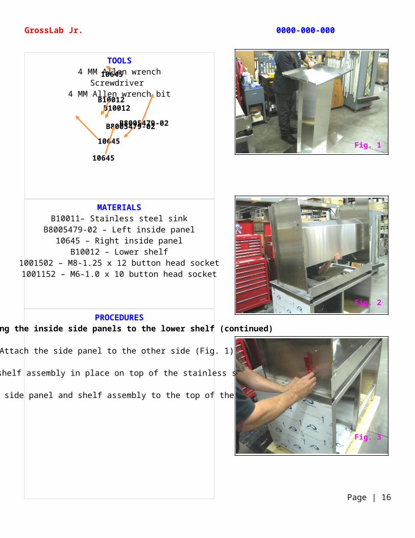
PROCEDURESAttaching the inside side panels to the lower shelf (continued)
Attach the side panel to the other side (Fig. 1).
Carefully lift the shelf assembly in place on top of the stainless steel sink (Fig. 2).
Attach the screws securing the side panel and shelf assembly to the top of the stainless steel sink (Fig. 3).
TOOLS4 MM Allen wrench
Screwdriver 4 MM Allen wrench bit
GrossLab Jr. 0000-000-000
Page | 16
B10012
B8005479-02
10645
10645
10645
B10012
B8005479-02
Fig. 1
Fig. 3
Fig. 2
MATERIALS10634 – Upper shelf
10632 – Filter frame rack10631 – Filter access panels (2 needed)
1001145 – M6-1 pan head screw1001144 – M6-1 hex nut
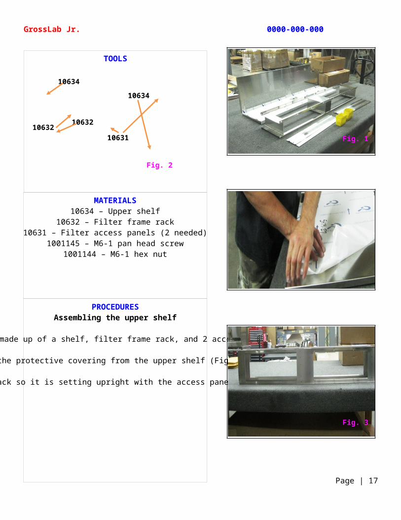
PROCEDURESAssembling the upper shelf
The upper shelf is made up of a shelf, filter frame rack, and 2 access panels (Fig. 1).
Peel the protective covering from the upper shelf (Fig. 2).
Position the filter frame rack so it is setting upright with the access panel holes facing you (Fig. 3).
TOOLS
GrossLab Jr. 0000-000-000
Page | 17
Fig. 2
10634
1063210631
10634
10632
Fig. 1
Fig. 3
MATERIALS10634 – Upper shelf
10632 – Filter frame rack10631 – Filter access panels (2 needed)
1001145 – #6 lock washer1001144 – M6-1 hex nut
PROCEDURESAssembling the upper shelf (continued)
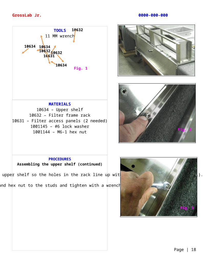
Fit the filter frame rack over the upper shelf so the holes in the rack line up with the studs on the shelf (Fig. 1).
Attach a lock washer and hex nut to the studs and tighten with a wrench (Fig. 2 and Fig. 3).
TOOLS11 MM wrench
GrossLab Jr. 0000-000-000
Page | 18
Fig. 110634
10632
10631
10634 1063410632 10632
Fig. 3
Fig. 2
MATERIALS10634 – Upper shelf
10632 – Filter frame rack10631 – Filter access panels (2 needed)
1001145 – #6 lock washer1001144 – M6-1 hex nut
100652 – Grommet
PROCEDURESAssembling the upper shelf (continued)
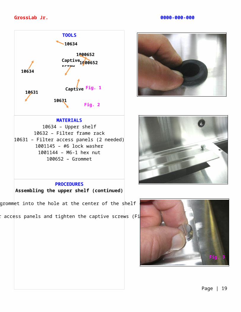
Insert a grommet into the hole at the center of the shelf (Fig. 1).
Line up the filter access panels and tighten the captive screws (Fig. 2 and Fig. 3).
TOOLS
GrossLab Jr. 0000-000-000
Page | 19
Fig. 1
Fig. 2
10634
1000652
10634
1000652
10631
Captive screw
10631Captive screw
Fig. 3
MATERIALS10634 – Upper shelf
10632 – Filter frame rack10631 – Filter access panels (2 needed)
1901080 – Solid state relay1001274 – IEC connector
B1004242 – Phillips M3-0.5 x 8 flat head screw
PROCEDURESAssembling the upper shelf (continued)
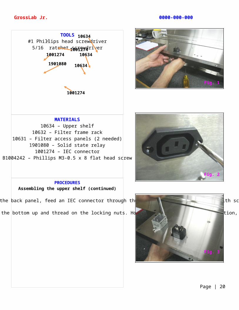
With the upper shelf positioned with easy access to the back panel, feed an IEC connector through the hole (Fig. 1) and secure it with screws (Fig. 2).
Position a solid state relay on the panel next to the IEC connector. Insert the screws from the bottom up and thread on the locking nuts. Holding the screws firmly in position, tighten the nuts using a ratchet screwdriver (Fig. 3).
TOOLS#1 Phillips head screwdriver
5/16” ratchet screwdriver
GrossLab Jr. 0000-000-000
Page | 20
10634
10634
10634
10012741001274
1001274
1901080
Fig. 1
Fig. 3
Fig. 2
MATERIALS10634 – Upper shelf
10632 – Filter frame rack10631 – Filter access panels (2 needed)
B10014 – Dual power entry panel1001760 – AC filter
1001274 – IEC connector (2 needed)Caution decal Power decal
Disposal decalB1004242 – Phillips M3-0.5 x 8 flat head screw
Locking nutPROCEDURES
Assembling the upper shelf (continued)
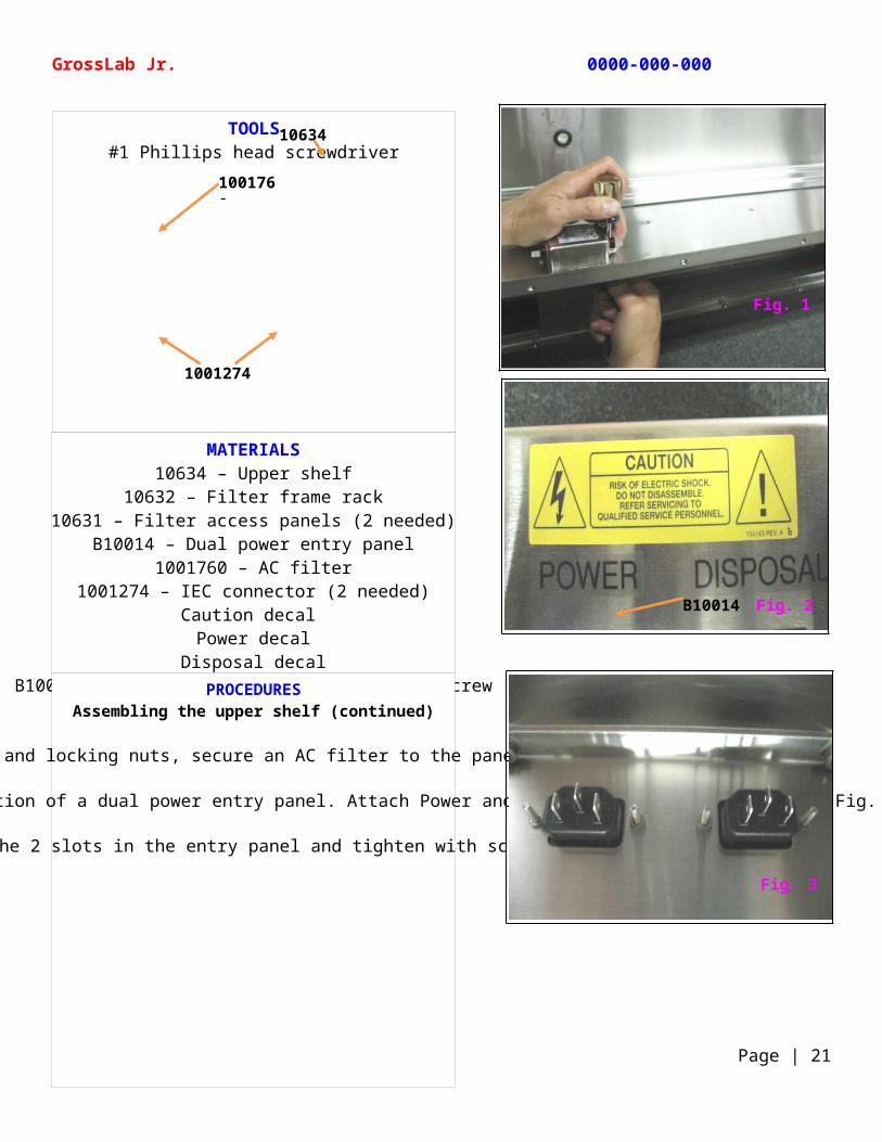
Using screws and locking nuts, secure an AC filter to the panel (Fig. 1).
Center a caution decal to the upper portion of a dual power entry panel. Attach Power and Disposal decals to the panel (Fig. 2).
Feed 2 IEC connectors through the 2 slots in the entry panel and tighten with screws and locking nuts (Fig. 3).
TOOLS#1 Phillips head screwdriver
GrossLab Jr. 0000-000-000
Page | 21
10634
1001760
1001274
Fig. 1
Fig. 3
Fig. 2B10014
MATERIALS10634 – Upper shelf
10632 – Filter frame rack10631 – Filter access panels (2 needed)
1001274 – IEC connector (2 needed)B10014 – Dual power entry panel
10639 – Entry panel backB1004242 – Phillips M3-0.5 x 8 flat head screw
19610 – Grounding label
PROCEDURESAssembling the upper shelf (continued)
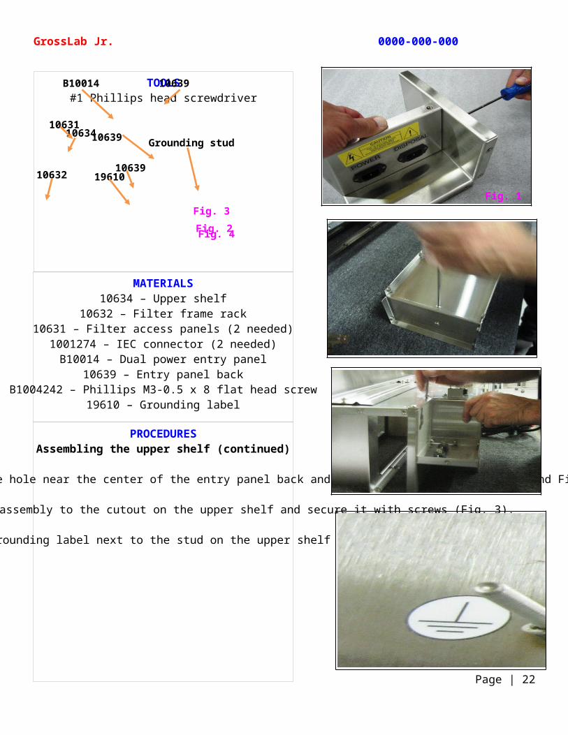
Line up the dual power entry panel with the hole near the center of the entry panel back and tighten with a screw (Fig. 1 and Fig. 2).
Attach the entry panel back assembly to the cutout on the upper shelf and secure it with screws (Fig. 3).
Attach a grounding label next to the stud on the upper shelf (Fig. 4).
TOOLS#1 Phillips head screwdriver
GrossLab Jr. 0000-000-000
Page | 22
Fig. 2Fig. 3
Fig. 4
B10014 10639
10639
10639
19610
Grounding stud10634
10631
10632
Fig. 1
MATERIALS235023 – Line cord stock cable
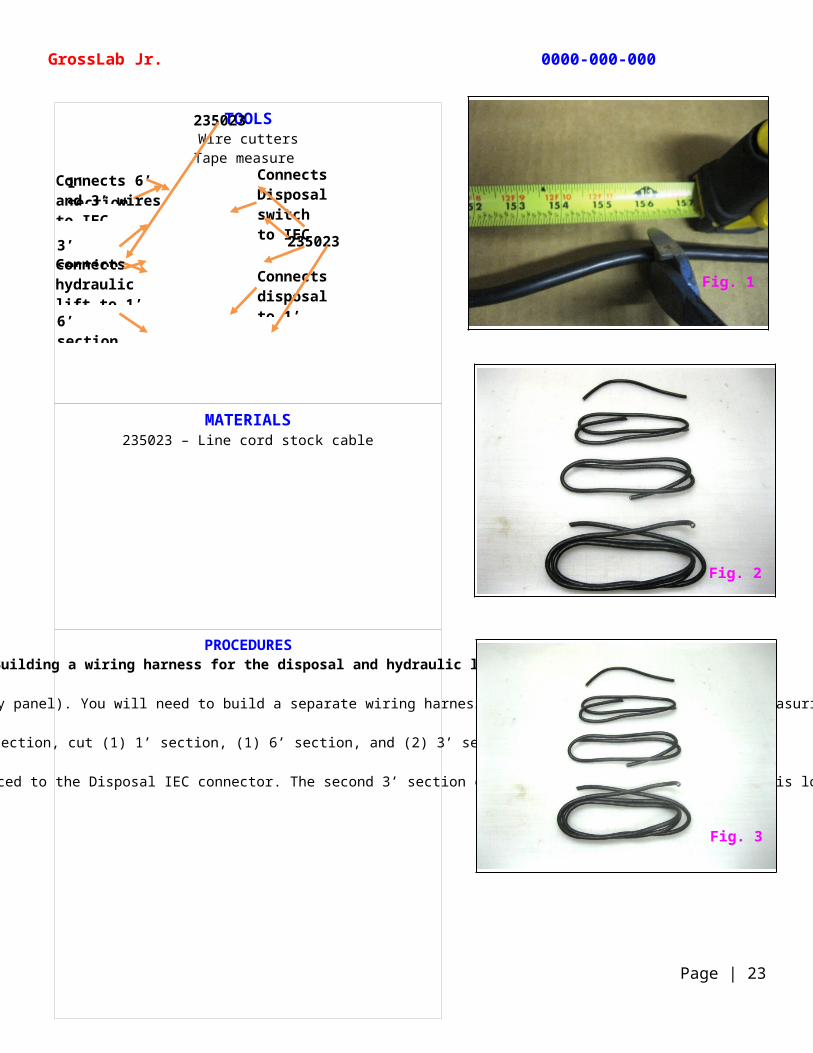
PROCEDURESBuilding a wiring harness for the disposal and hydraulic lift
The disposal and hydraulic lift use a separate power supply (labeled Disposal on the dual entry panel). You will need to build a separate wiring harness for these 2 functions. Start by measuring and cutting (1) 13’ section of line cord stock cable.
From this 13’ section, cut (1) 1’ section, (1) 6’ section, and (2) 3’ sections (Fig. 2).
The 6’ section will power the disposal and (1) 3’ section will power the hydraulic lift. Both are spliced to the 1’ section, which in turn, is spliced to the Disposal IEC connector. The second 3’ section connects the Disposal switch, which is located at the front of the GrossLab Jr. assembly, to the Disposal IEC connector located at the back (Fig. 3).
TOOLSWire cutters
Tape measure
GrossLab Jr. 0000-000-000
Page | 23
235023
1’ section of 235023
3’ section of 235023
6’ section of 235023
Connects 6’ and 3’ wires to IEC connector
Connects Disposal switch to IEC connector
Connects hydraulic lift to 1’ wire
Connects disposal to 1’ wires connector
235023
Fig. 1
Fig. 3
Fig. 2
MATERIALS235023 – Line cord stock cable
235046 – Closed-end connectors
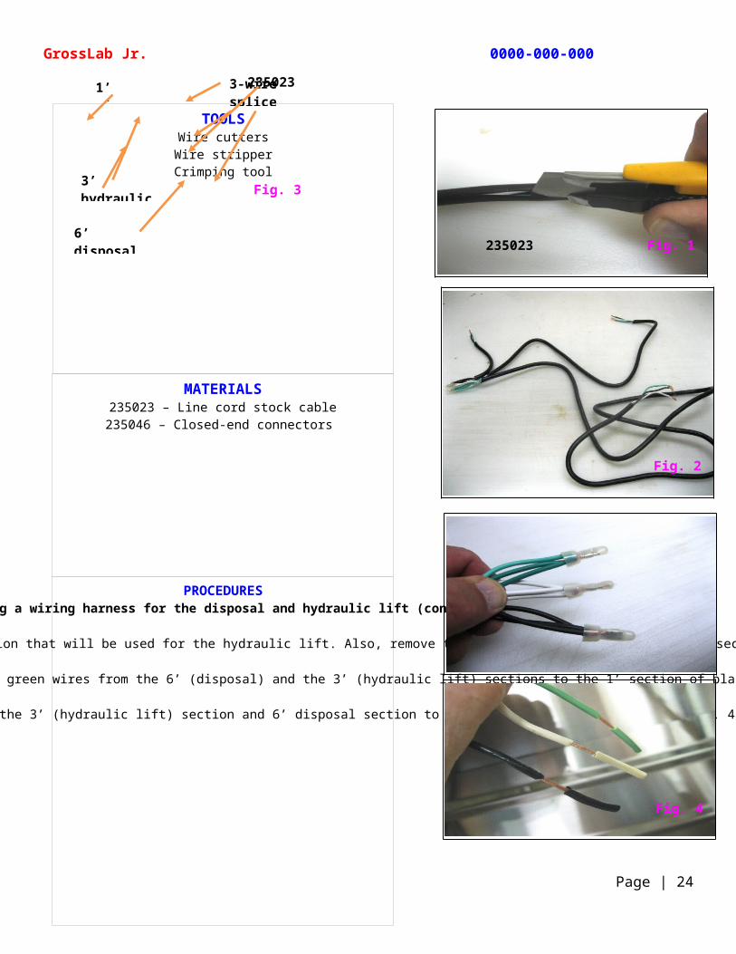
PROCEDURESBuilding a wiring harness for the disposal and hydraulic lift (continued)
Using a utility knife, cut and remove about 6” off the outer sleeve of line cord cable on both ends of (1) 3’ section that will be used for the hydraulic lift. Also, remove the outer sleeve on the 6’ disposal section and the 1’ section exposing the white, black, and green wires (Fig. 1).
Remove about 2” of insulation from all exposed wires and using closed-end connectors connect the black, white, and green wires from the 6’ (disposal) and the 3’ (hydraulic lift) sections to the 1’ section of black, white, and green wires, making each a 3-wire splice (Fig. 2 and Fig. 3).
Slide the insulation back on the end of the 3’ (hydraulic lift) section and 6’ disposal section to help protect the exposed wires (Fig. 4).
TOOLSWire cuttersWire stripperCrimping tool
GrossLab Jr. 0000-000-000
Page | 24
Fig. 3
1’ wires
6’ disposal wires
3’ hydraulic lift wires
3-wire splice
235023
Fig. 4
Fig. 1235023
Fig. 2
MATERIALS235023 – Line cord stock cable
187086 – Cable ties
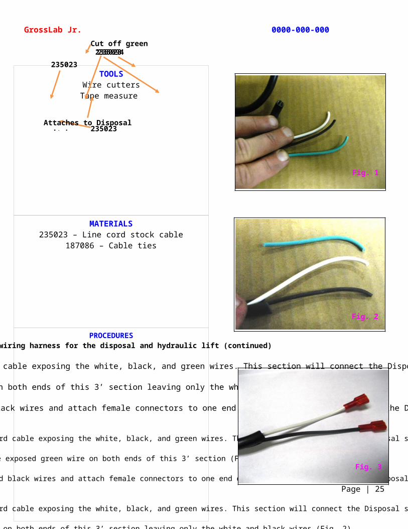
PROCEDURESBuilding a wiring harness for the disposal and hydraulic lift (continued)
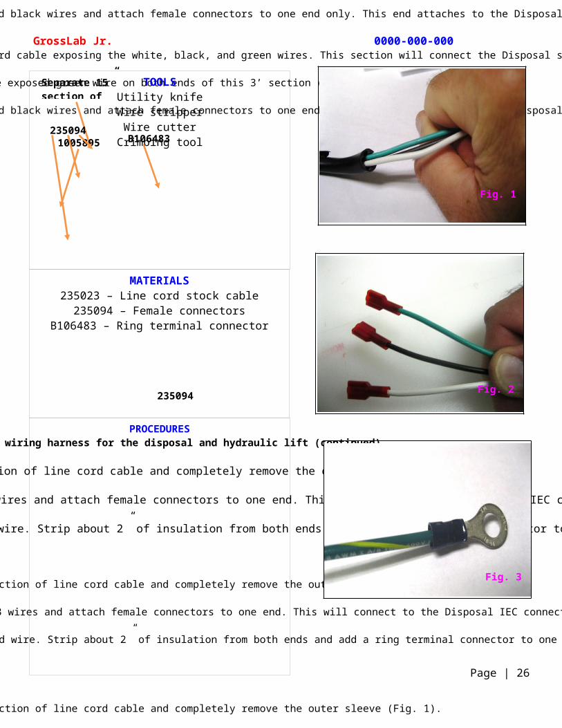
Remove about 6” of the outer sleeve on both ends of the remaining 3’ section of line cord cable exposing the white, black, and green wires. This section will connect the Disposal switch to the IEC Disposal connector (Fig. 1).
Cut off the exposed green wire on both ends of this 3’ section leaving only the white and black wires (Fig. 2).
Strip about 2” of insulation from both ends of the white and black wires and attach female connectors to one end only. This end will attach to the Disposal switch (Fig. 3).
Remove about 6” of the outer sleeve on both ends of the remaining 3’ section of line cord cable exposing the white, black, and green wires. This section will connect the Disposal switch to the IEC Disposal connector (Fig. 1).
Cut off the exposed green wire on both ends of this 3’ section (Fig. 2).
Strip about 2” of insulation from both ends of the white and black wires and attach female connectors to one end only. This end attaches to the Disposal switch (Fig. 3).
Remove about 6” of the outer sleeve on both ends of the remaining 3’ section of line cord cable exposing the white, black, and green wires. This section will connect the Disposal switch to the IEC Disposal connector (Fig. 1).
Cut off the exposed green wire on both ends of this 3’ section leaving only the white and black wires (Fig. 2).
Strip about 2” of insulation from both ends of the white and black wires and attach female connectors to one end only. This end attaches to the Disposal switch (Fig. 3).
Remove about 6” of the outer sleeve on both ends of the remaining 3’ section of line cord cable exposing the white, black, and green wires. This section will connect the Disposal switch to the IEC Disposal connector (Fig. 1).
Cut off the exposed green wire on both ends of this 3’ section (Fig. 2).
Strip about 2” of insulation from both ends of the white and black wires and attach female connectors to one end only. This end attaches to the Disposal switch (Fig. 3).
TOOLSWire cutters
Tape measure
GrossLab Jr. 0000-000-000
Page | 25
Cut off green wire
235023
235023235094235023
Attaches to Disposal switch
Fig. 1
Fig. 2
Fig. 3
MATERIALS235023 – Line cord stock cable235094 – Female connectors
B106483 – Ring terminal connector
PROCEDURESBuilding a wiring harness for the disposal and hydraulic lift (continued)
Cut a separate 15” section of line cord cable and completely remove the outer sleeve (Fig. 1).
Strip about 2” of insulation from both ends of the 3 wires and attach female connectors to one end. This will connect to the Disposal IEC connector (Fig. 2)
Cut (1) 12” section of green and yellow-striped ground wire. Strip about 2” of insulation from both ends and add a ring terminal connector to one end (Fig. 3).
TOOLSUtility knife
Wire stripperWire cutter
Crimping tool
GrossLab Jr. 0000-000-000
Page | 26
Separate 15” section of 235023
1005895 B106483
235094
235094
Fig. 1
Fig. 2
Fig. 3
MATERIALS235023 – Line cord stock cable235094 – Female connectors
235046 – Closed-end connectors187086 – Cable ties
PROCEDURESBuilding a wiring harness for the disposal and hydraulic lift (continued)
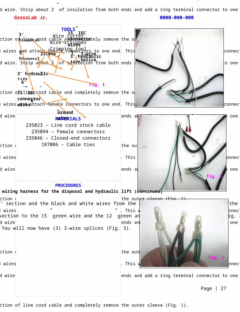
Using closed-end connectors, connect the black and white wires from the 1’ section and the black and white wires from the 3’ (Disposal switch) section to the 15” black and white wires (Fig. 1).
Then connect the green wire from the 1’ section to the 15” green wire and the 12” green and yellow-striped ground wire (Fig. 2).
You will now have (3) 3-wire splices (Fig. 3).
TOOLSWire cutter
Wire stripperCrimping tool
GrossLab Jr. 0000-000-000
Page | 27
Fig. 1
3-wire splice
235046 1’ wires3’ Disposal switch
3’ hydraulic lift
6’ disposal
Ground wire
15” IEC connector wires
3’ Disposal switch
3’ hydraulic lift
6’ disposal
15” IEC connector wires
1’ wires
Fig. 3
Fig. 2
MATERIALS235023 – Line cord stock cable
1005895 –Green and yellow-striped wire235094 – Female connectors
B106483 – Ring terminal connector235046 – Closed-end connectors
1901080 – Solid state relay1001274 – IEC connector
187086 – Cable ties
PROCEDURESBuilding a wiring harness for the disposal and hydraulic lift (continued)
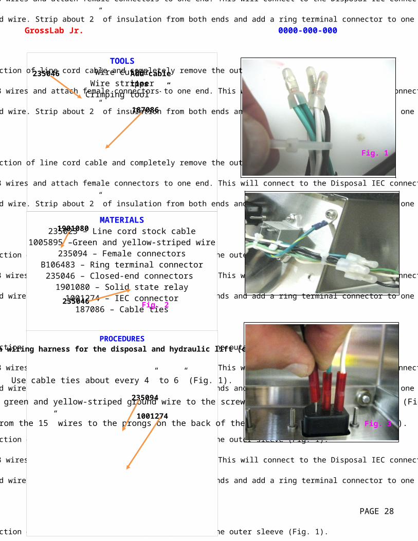
Use cable ties about every 4” to 6” (Fig. 1).
Attach the ring terminal connector on the green and yellow-striped ground wire to the screw next to the solid state relay. (Fig. 2).
Connect the 3 female connectors from the 15” wires to the prongs on the back of the Disposal IEC connector (Fig. 3).
TOOLSWire cutter
Wire stripperCrimping tool
GrossLab Jr. 0000-000-000
PAGE 28
Fig. 2
1901080
235094
235046
1001274
Add cable ties every 4” – 6”
235046
187086
Fig. 1
Fig. 3
MATERIALS235023 – Line cord stock cable
22 AWG Orange wire22 AWG Blue wire
22 AWG Green wire235094 – Female connectors
187086 – Cable ties
PROCEDURESBuilding a wiring harness for the disposal and hydraulic lift (continued)
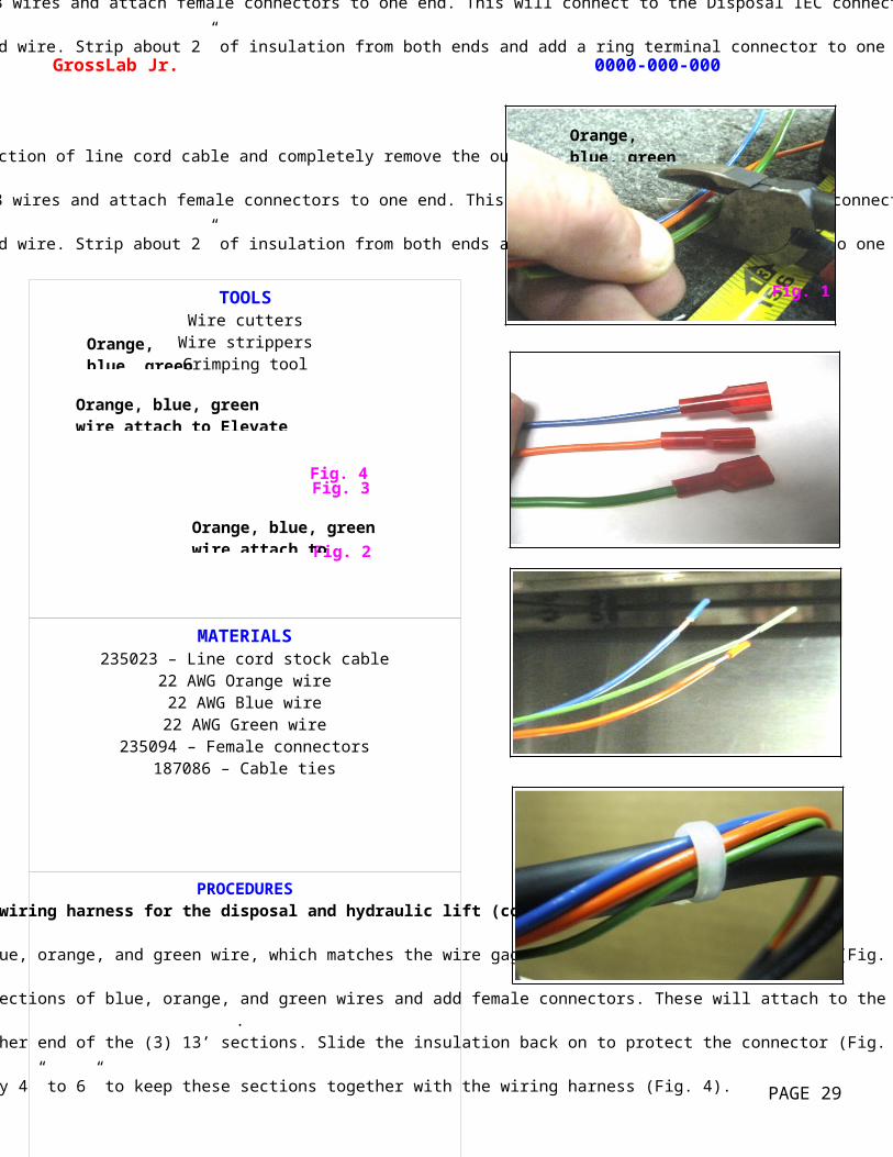
Measure and cut (3) 13’ sections of 22 AWG blue, orange, and green wire, which matches the wire gage for the hydraulic lift control (Fig. 1).
Strip away about 2” of insulation from one end of each of the (3) 13’ sections of blue, orange, and green wires and add female connectors. These will attach to the Elevate switch later (Fig. 2).
Strip away about 2” of insulation from the other end of the (3) 13’ sections. Slide the insulation back on to protect the connector (Fig. 3).
Use cable ties about every 4” to 6” to keep these sections together with the wiring harness (Fig. 4).
TOOLSWire cutters
Wire strippersCrimping tool
GrossLab Jr. 0000-000-000
PAGE 29
Fig. 3
Fig. 2
Fig. 4
Orange, blue, green wire attach to Elevate switch
Orange, blue, green wire attach to hydraulic lift control
Orange, blue, green wire
Fig. 1
Orange, blue, green wire
MATERIALS235023 – Line cord stock cable
22 AWG Orange wire22 AWG Blue wire
22 AWG Green wire10634 – Upper shelf
10632 – Filter frame rack10631 – Filter access panels (2 needed)
10643 – Louvered exhaust panelB8005479-02 – Left inside panel
10645 – Right inside panelB10012 – Lower shelf
1001152 – M6-1.0 x 10 button head socket
PROCEDURESAssembling the upper shelf to the lower shelf
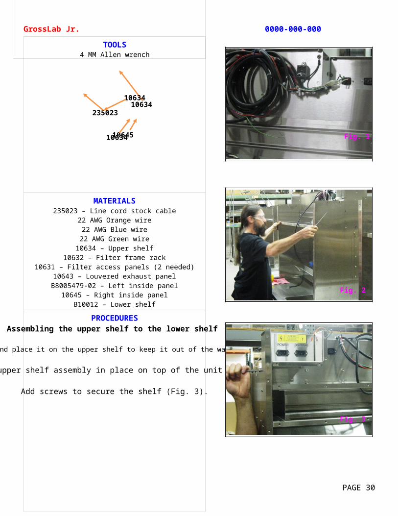
Roll up the wiring harness and place it on the upper shelf to keep it out of the way until you need it (Fig. 1).
Set the upper shelf assembly in place on top of the unit (Fig. 2).
Add screws to secure the shelf (Fig. 3).
TOOLS4 MM Allen wrench
GrossLab Jr. 0000-000-000
PAGE 30
23502310634
10645
10634
10634Fig. 1
Fig. 3
Fig. 2
MATERIALS10634 – Upper shelf
10632 – Filter frame rack10631 – Filter access panels (2 needed)
10643 – Louvered exhaust panelB8005479-02 – Left inside panel
10645 – Right inside panelB10012 – Lower shelf
1001152 – M6-1.0 x 10 button head socket1000652 – Grommet
PROCEDURESAssembling the upper shelf to the lower shelf (continued)
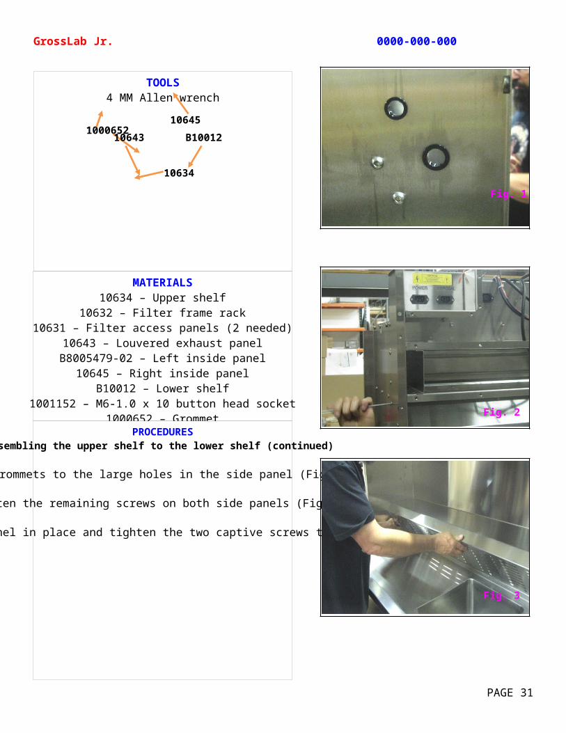
Add grommets to the large holes in the side panel (Fig. 1).
Tighten the remaining screws on both side panels (Fig. 2).
Set the louvered exhaust panel in place and tighten the two captive screws to lock it in place (Fig. 3).
TOOLS4 MM Allen wrench
GrossLab Jr. 0000-000-000
PAGE 31
100065210645
10634
10643 B10012
Fig. 1
Fig. 3
Fig. 2
MATERIALS235023 – Line cord stock cable
10645 – Right inside panel1000665 – Flanged terminal connector
1000696 – Liquid-tight strain-relief connector1000652 – Grommet
PROCEDURESPreparing the disposal unit cable
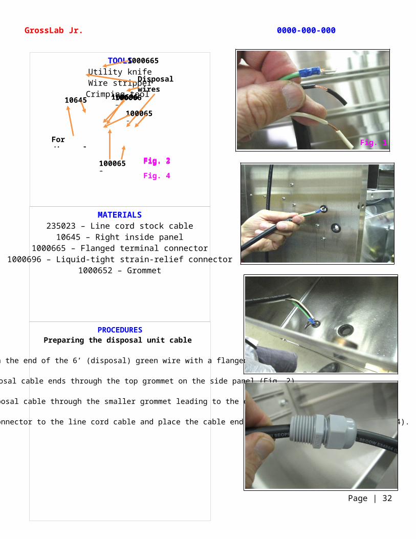
Replace the loose insulation on the end of the 6’ (disposal) green wire with a flanged terminal connector (Fig. 1).
Feed the disposal cable ends through the top grommet on the side panel (Fig. 2).
Then feed the disposal cable through the smaller grommet leading to the cabinet (Fig. 3).
Attach a liquid-tight strain-relief connector to the line cord cable and place the cable end inside the cabinet for now (Fig. 4).
TOOLSUtility knife
Wire stripperCrimping tool
GrossLab Jr. 0000-000-000
Page | 32
Fig. 2Fig. 3
Fig. 4
1000665
Disposal wires
10645 1000665
1000652
1000652
For disposal
100696
Fig. 1
MATERIALS235023 – Line cord stock cable
Hydraulic lift power cord
PROCEDURESConnecting the wiring harness to the hydraulic lift
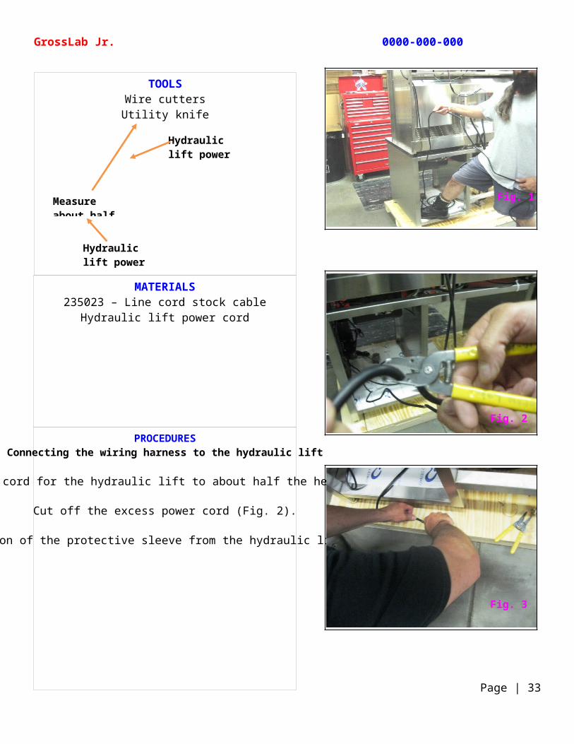
Roughly measure the power cord for the hydraulic lift to about half the height of the unit (Fig. 1).
Cut off the excess power cord (Fig. 2).
Remove about a 6” section of the protective sleeve from the hydraulic lift power cord (Fig. 3).
TOOLSWire cuttersUtility knife
GrossLab Jr. 0000-000-000
Page | 33
Measure about half way up
Hydraulic lift power cord
Hydraulic lift power cord
Fig. 1
Fig. 3
Fig. 2
MATERIALS235023 – Line cord stock cable
Hydraulic lift power cord235046 – Closed-end connectors
22 AWG orange wire22 AWG blue wire
22 AWG green wire187086 – Cable ties
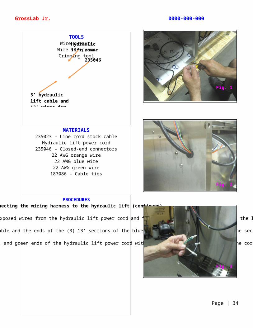
PROCEDURESConnecting the wiring harness to the hydraulic lift (continued)
Strip off about 2” of insulation from the ends of the 3 exposed wires from the hydraulic lift power cord and feed them up through the grommet in the lower shelf (Fig. 1).
Feed the spliced end of the 3’ (hydraulic lift) section of the line cord cable and the ends of the (3) 13’ sections of the blue, orange, and green wire through the second grommet on the side panel (Fig 2).
Using closed-end connectors, connect the black, white, and green ends of the hydraulic lift power cord with the ends of the 3’ section of line cord cable (Fig. 3).
TOOLSWire cutters
Wire strippersCrimping tool
GrossLab Jr. 0000-000-000
Page | 34
Hydraulic lift power cord
3’ hydraulic lift cable and 13’ wires for Elevate switch
235046
Fig. 1
Fig. 3
Fig. 2
MATERIALS235023 – Line cord stock cable
Hydraulic lift power cordHydraulic lift switch
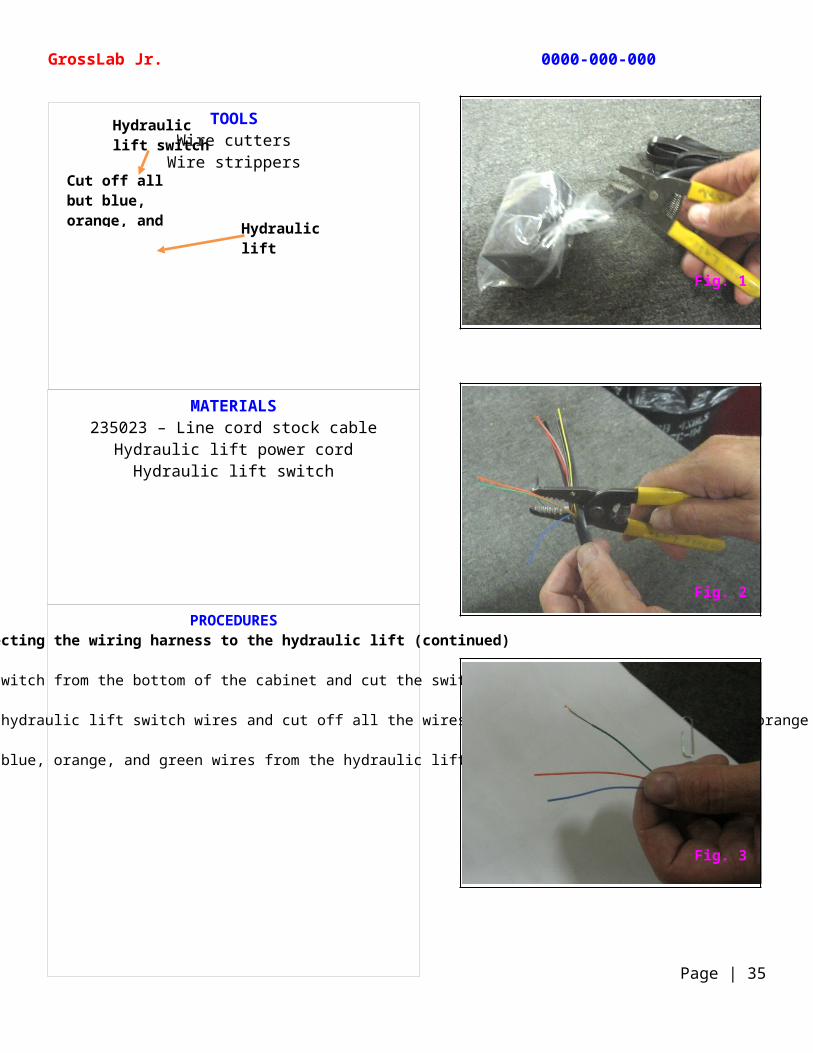
PROCEDURESConnecting the wiring harness to the hydraulic lift (continued)
Remove the hydraulic lift switch from the bottom of the cabinet and cut the switch from the cable (Fig. 1).
Remove about 6” of the protective sleeve to expose the hydraulic lift switch wires and cut off all the wires except for the blue, green, and orange wires (Fig. 2).
Strip the ends of the blue, orange, and green wires from the hydraulic lift switch wires (Fig.3).
TOOLSWire cutters
Wire strippers
GrossLab Jr. 0000-000-000
Page | 35
Hydraulic lift switch
Hydraulic lift switch wires
Cut off all but blue, orange, and green
Fig. 1
Fig. 3
Fig. 2
MATERIALS235023 – Line cord stock cable
235046 – Closed-end connectors22 AWG orange wire
22 AWG blue wire22 AWG green wire187086 – Cable ties
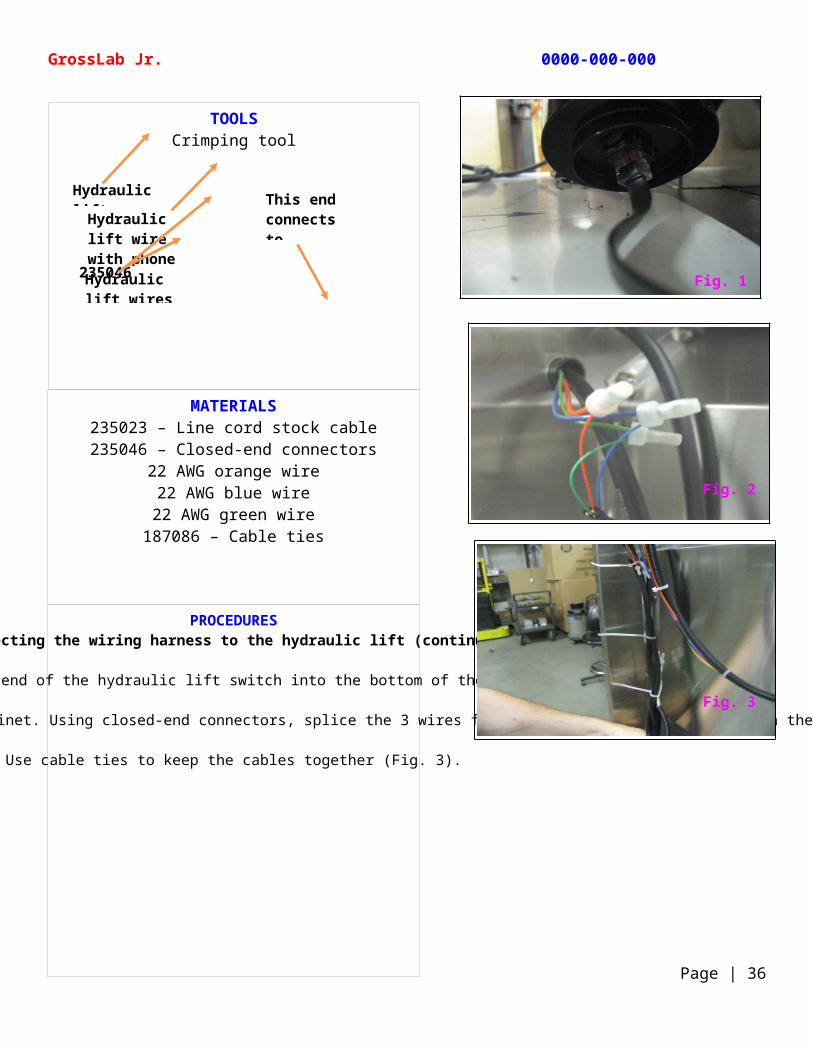
PROCEDURESConnecting the wiring harness to the hydraulic lift (continued)
Plug the jack on the other end of the hydraulic lift switch into the bottom of the hydraulic lift (Fig. 1).
Feed the end of the hydraulic lift switch cable up through the smaller grommet leading from the cabinet. Using closed-end connectors, splice the 3 wires from the hydraulic lift switch with the 13’ sections of the orange, green, and blue wires (Fig. 2).
Use cable ties to keep the cables together (Fig. 3).
TOOLSCrimping tool
GrossLab Jr. 0000-000-000
Page | 36
Hydraulic lift
Hydraulic lift wire with phone jack connection235046Hydraulic lift wires
This end connects to switches
Fig. 1
Fig. 3
Fig. 2
MATERIALSB8005479-02 – Left inside panel
10645 – Right inside panelB10012 – Lower shelf
B1001245 – Outside panel 1001152 – M6-1.0 x 10 button head socket
10634 – Upper shelf
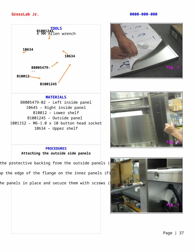
PROCEDURESAttaching the outside side panels
Remove the protective backing from the outside panels (Fig. 1).
Line up the edge of the flange on the inner panels (Fig. 2).
Swing the panels in place and secure them with screws (Fig. 3).
TOOLS4 MM Allen wrench
GrossLab Jr. 0000-000-000
Page | 37
B1001245
B1001245
B8005479-02
B10012
10634
10634
Fig. 1
Fig. 3
Fig. 2
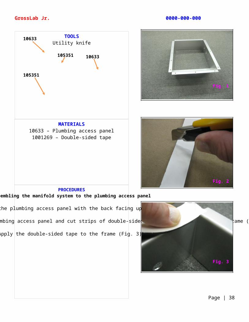
MATERIALS10633 – Plumbing access panel1001269 – Double-sided tape
PROCEDURESAssembling the manifold system to the plumbing access panel
Position the plumbing access panel with the back facing up (Fig. 1).
Measure the top, bottom, and side of the plumbing access panel and cut strips of double-sided tape to fit the back of the frame (Fig. 2).
Apply the double-sided tape to the frame (Fig. 3).
TOOLSUtility knife
GrossLab Jr. 0000-000-000
Page | 38
10633
105351
10633105351
Fig. 1
Fig. 3
Fig. 2
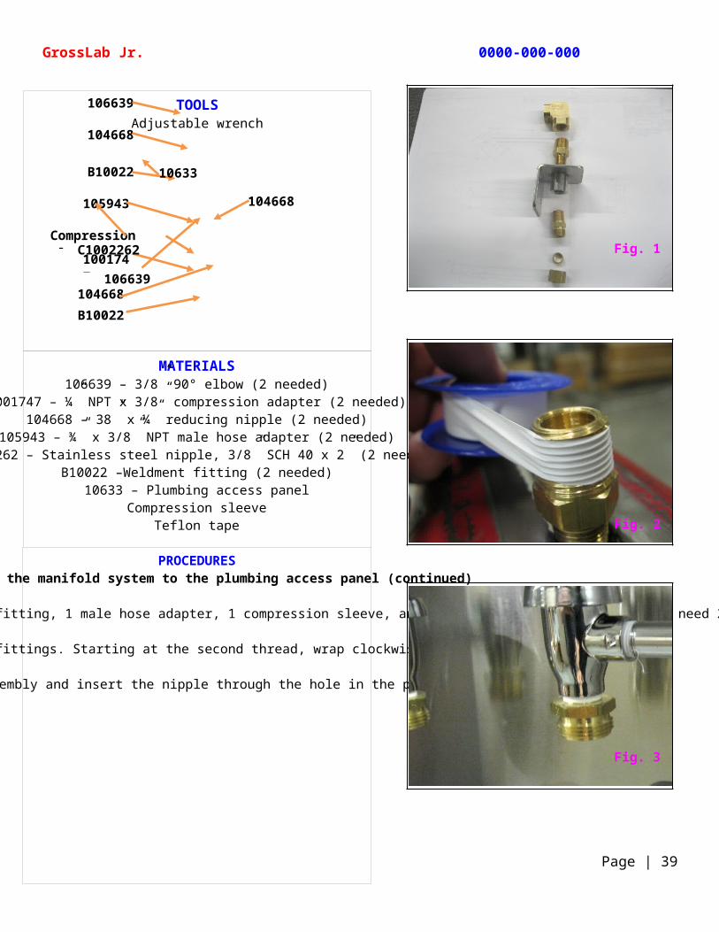
MATERIALS106639 – 3/8” 90° elbow (2 needed)
1001747 – ¼” NPT x 3/8” compression adapter (2 needed)104668 – 38” x ¼” reducing nipple (2 needed)
105943 – ¾” x 3/8” NPT male hose adapter (2 needed)C1002262 – Stainless steel nipple, 3/8” SCH 40 x 2” (2 needed)
B10022 –Weldment fitting (2 needed)10633 – Plumbing access panel
Compression sleeveTeflon tape
PROCEDURESAssembling the manifold system to the plumbing access panel (continued)
The weldment fitting assembly uses (1) 90° elbow, 1 reducing nipple, 1 weldment fitting, 1 male hose adapter, 1 compression sleeve, and 1 compression adapter. You will need 2 weldment fitting assemblies (Fig 1).
Apply Teflon tape to all male fittings. Starting at the second thread, wrap clockwise 4 complete turns (Fig. 2).
Attach a nipple to the elbow assembly and insert the nipple through the hole in the plumbing access panel (Fig. 3).
TOOLSAdjustable wrench
GrossLab Jr. 0000-000-000
Page | 39
106639
104668
B10022
105943
Compression sleeve
1001747C1002262
104668
106639
B10022104668
10633
Fig. 1
Fig. 3
Fig. 2
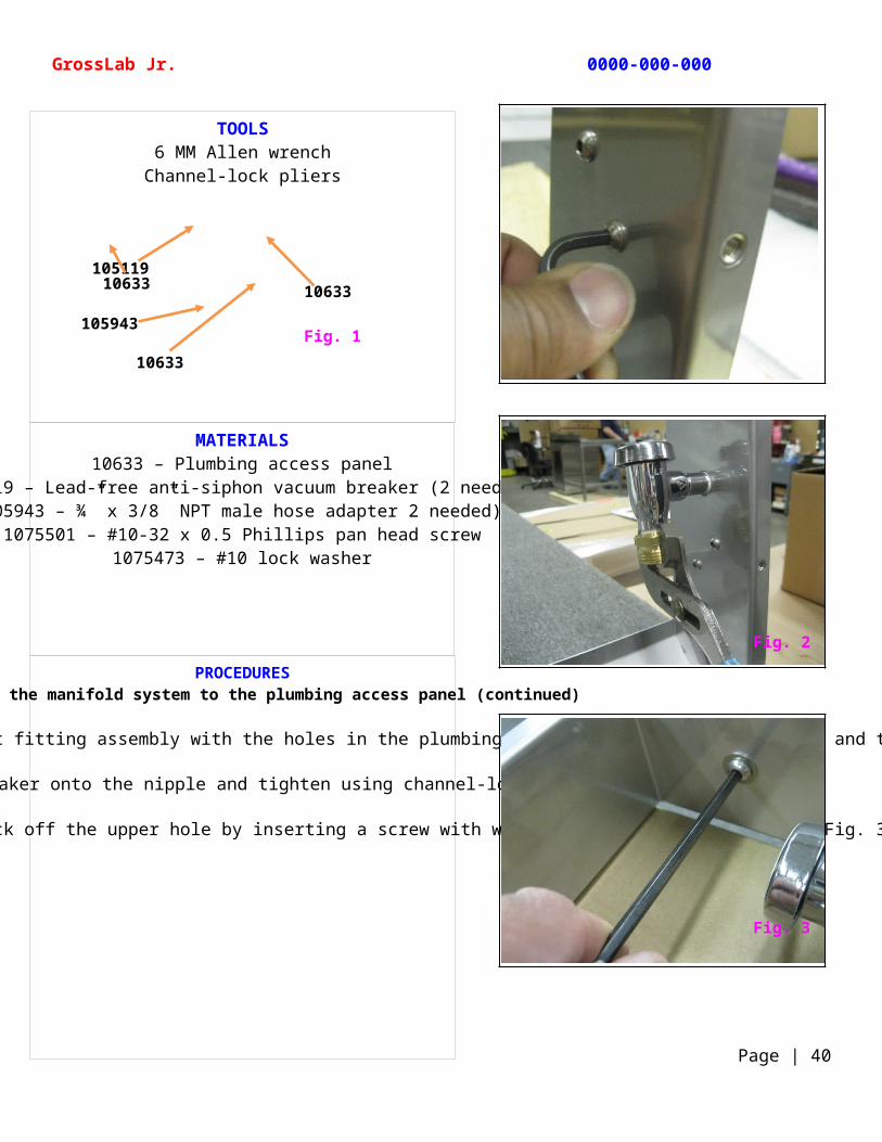
MATERIALS10633 – Plumbing access panel
105119 – Lead-free anti-siphon vacuum breaker (2 needed)105943 – ¾” x 3/8” NPT male hose adapter 2 needed)
1075501 – #10-32 x 0.5 Phillips pan head screw1075473 – #10 lock washer
PROCEDURESAssembling the manifold system to the plumbing access panel (continued)
To secure the weldment fitting to the plumbing access paned, line up the holes in the weldment fitting assembly with the holes in the plumbing access panel, insert 2 screws, and thread on the lock washers. Tighten the screws (Fig. 1).
Thread the vacuum breaker onto the nipple and tighten using channel-lock pliers (Fig. 2).
If the unit is not using a solenoid, block off the upper hole by inserting a screw with washer, add a nut, and tighten (Fig. 3).
TOOLS6 MM Allen wrenchChannel-lock pliers
GrossLab Jr. 0000-000-000
Page | 40
Fig. 1
10633
10633
105119
105943
10633
Fig. 3
Fig. 2
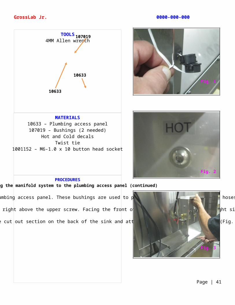
MATERIALS10633 – Plumbing access panel107019 – Bushings (2 needed)
Hot and Cold decalsTwist tie
1001152 – M6-1.0 x 10 button head socket
PROCEDURESAssembling the manifold system to the plumbing access panel (continued)
Using a twist tie, attach 2 bushings to the plumbing access panel. These bushings are used to protect the braided water supply hoses (Fig. 1).
Add the Hot and Cold decals to the inside of the plumbing access panel, right above the upper screw. Facing the front of the panel, Hot goes on the right side, cold on the left side (Fig. 2).
Install the plumbing access panel to the cut out section on the back of the sink and attach screws to hold it in place (Fig. 3).
TOOLS4MM Allen wrench
GrossLab Jr. 0000-000-000
Page | 41
107019
10633
10633
Fig. 1
Fig. 3
Fig. 2
MATERIALSB10011 – Stainless steel sink
B8005479-06 – Elevating stand assembly Cleaning solution1000845 – Silicone sealant
187086 – Cable ties21200-72068 – 2” painters tape
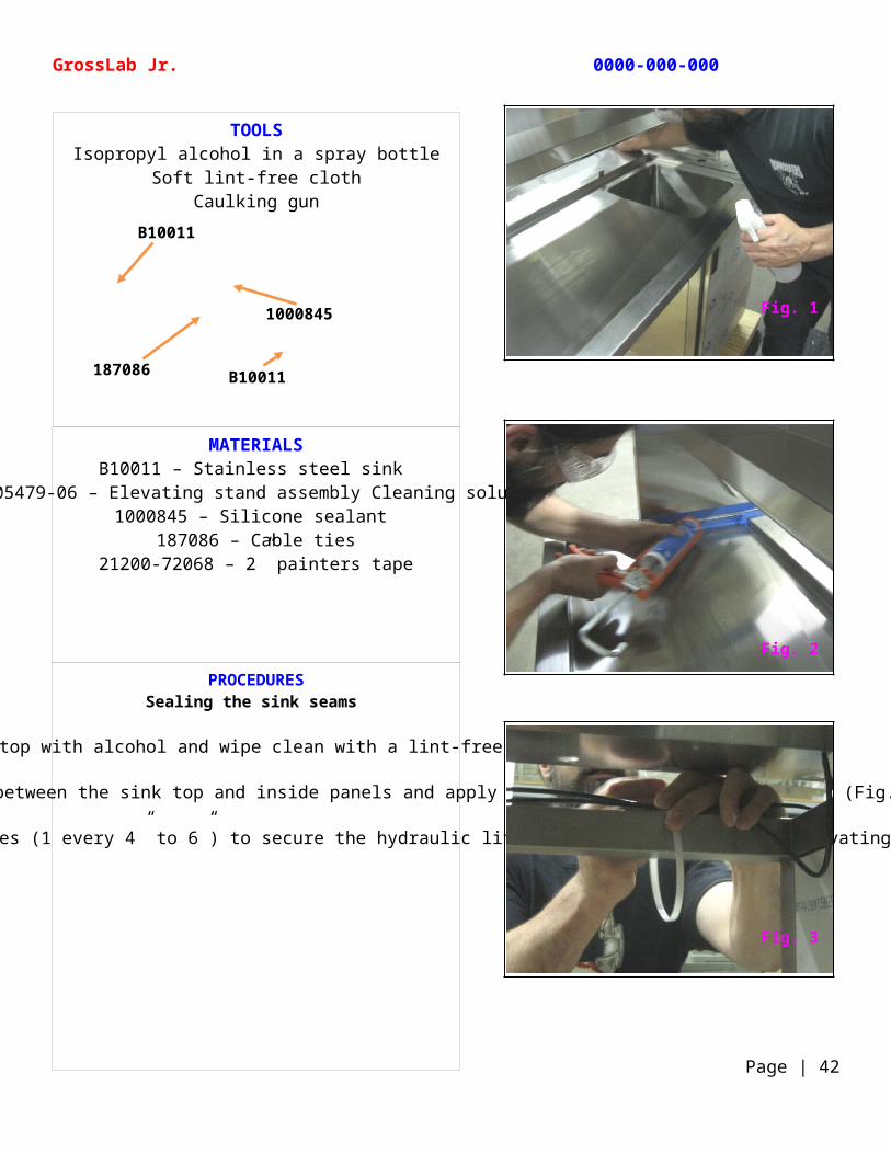
PROCEDURESSealing the sink seams
Spray the sink top with alcohol and wipe clean with a lint-free cloth (Fig. 1).
Tape the areas above and below the seam between the sink top and inside panels and apply a silicone sealant to the seams (Fig. 2).
To keep the hydraulic lift cables from snagging, use cable ties (1 every 4” to 6”) to secure the hydraulic lift cables to the top of the elevating stand assembly (Fig. 3).
TOOLSIsopropyl alcohol in a spray bottle
Soft lint-free clothCaulking gun
GrossLab Jr. 0000-000-000
Page | 42
B10011
B10011
1000845
187086
Fig. 1
Fig. 3
Fig. 2
MATERIALSB1000473 – Faucet with pull out spray spout
C1001329 – Door mounting hingeC1001330 – Cabinet mount hinge
Hinge assembly – C1001329 + C1001330
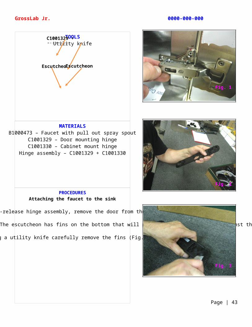
PROCEDURESAttaching the faucet to the sink
Using the quick-release hinge assembly, remove the door from the unit (Fig. 1).
Open the faucet assembly box and remove the escutcheon. The escutcheon has fins on the bottom that will prevent it from lying flat against the sink top (Fig. 2).
Using a utility knife carefully remove the fins (Fig. 3).
TOOLSUtility knife
GrossLab Jr. 0000-000-000
Page | 43
C1001329 + C1001330
Escutcheon Escutcheon
Fig. 1
Fig. 3
Fig. 2
MATERIALSB10011 – Stainless steel sink
B1000473 – Faucet with pull out spray spoutBolt
WasherNut
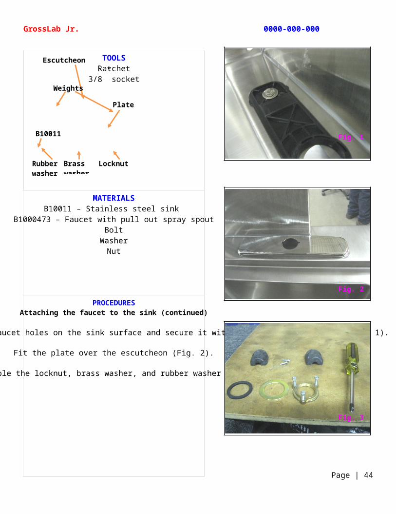
PROCEDURESAttaching the faucet to the sink (continued)
Position the escutcheon over the faucet holes on the sink surface and secure it with a bolt, washer, and nut (Fig. 1).
Fit the plate over the escutcheon (Fig. 2).
Disassemble the locknut, brass washer, and rubber washer (Fig. 3).
TOOLSRatchet
3/8” socket
GrossLab Jr. 0000-000-000
Page | 44
Escutcheon
B10011
Plate
Weights
Locknut Brass washer
Rubber washer
Fig. 1
Fig. 3
Fig. 2
MATERIALSB1000473 – Faucet with pull out spray spout
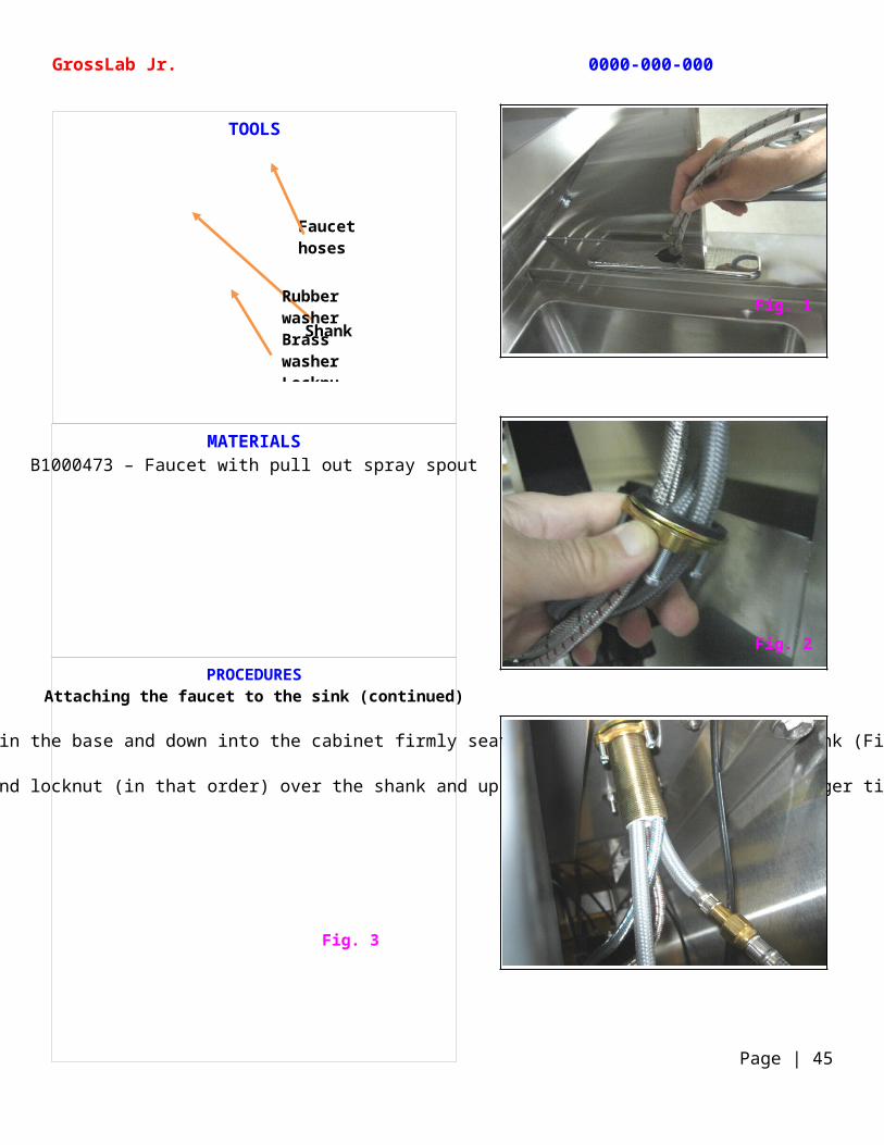
PROCEDURESAttaching the faucet to the sink (continued)
Feed the hoses and shank through the hole in the base and down into the cabinet firmly seating the spout base onto the sink (Fig. 1).
Working from inside the cabinet, slide the rubber washer, brass washer, and locknut (in that order) over the shank and up to the bottom of the sink. Finger tighten each screw (Fig. 2 and Fig. 3).
TOOLS
GrossLab Jr. 0000-000-000
Page | 45
Faucet hoses
Shank
Rubber washerBrass washer Locknut
Fig. 3
Fig. 1
Fig. 2
MATERIALSB1000473 – Faucet with pull out spray spout
PROCEDURESAttaching the faucet to the sink (continued)
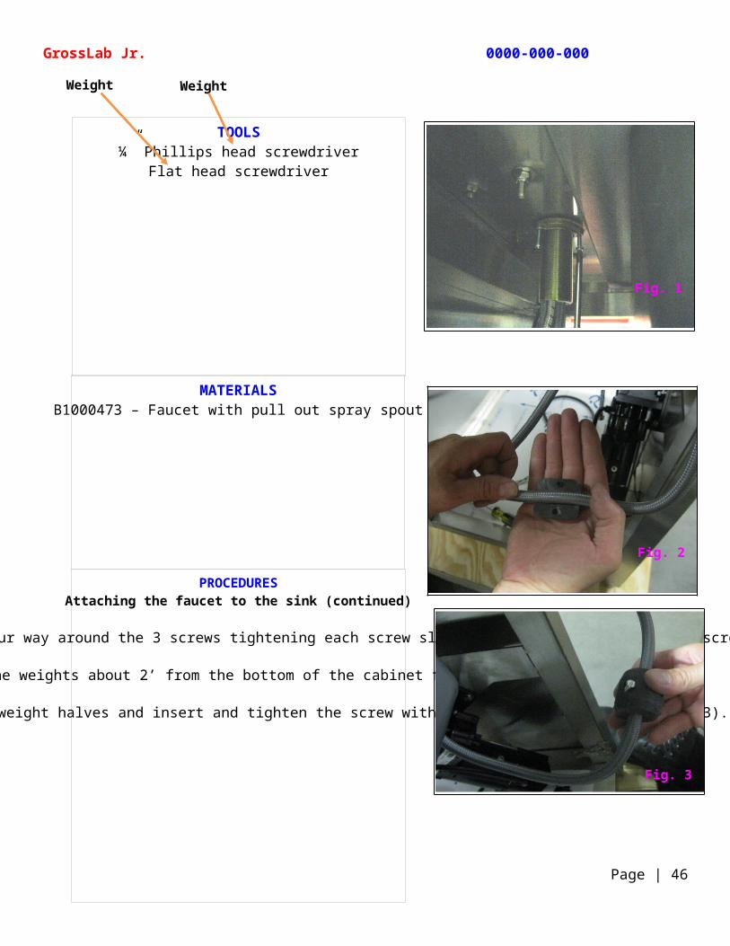
Using a Phillips head screwdriver, tighten each screw on the locknut. Work your way around the 3 screws tightening each screw slightly each time until all the screws are snug and the pressure is even (Fig. 1).
Install the weights about 2’ from the bottom of the cabinet floor (Fig. 2).
Line up the holes on the two weight halves and insert and tighten the screw with a flat head screwdriver (Fig. 3).
TOOLS¼” Phillips head screwdriver
Flat head screwdriver
GrossLab Jr. 0000-000-000
Page | 46
Weight Weight
Fig. 1
Fig. 2
Fig. 3
MATERIALSB1002514 – Stainless steel braided water supply hose (2 needed)
107019 – Bushings (2 needed — attached to the plumbing access panel)
PROCEDURESAttaching the faucet to the sink (continued)
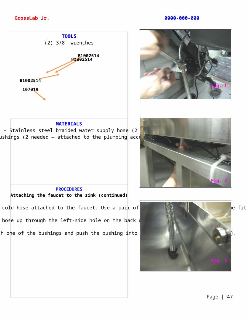
Thread one end of a braided water supply hose to the cold hose attached to the faucet. Use a pair of wrenches to securely tighten the fitting (Fig. 1).
Feed the water supply hose up through the left-side hole on the back of the sink (Fig. 2).
Slide the water supply hose through one of the bushings and push the bushing into the hole until it locks (Fig. 3).
TOOLS(2) 3/8” wrenches
GrossLab Jr. 0000-000-000
Page | 47
B1002514
B1002514B1002514
107019 Fig. 1
Fig. 3
Fig. 2
MATERIALSB1002514 – Stainless steel braided water supply hose (2 needed)
107019 – Bushings (2 needed — attached to the plumbing access panel)B10016-05 – Sink support bar
187086 – Cable ties
PROCEDURESAttaching the faucet to the sink (continued)
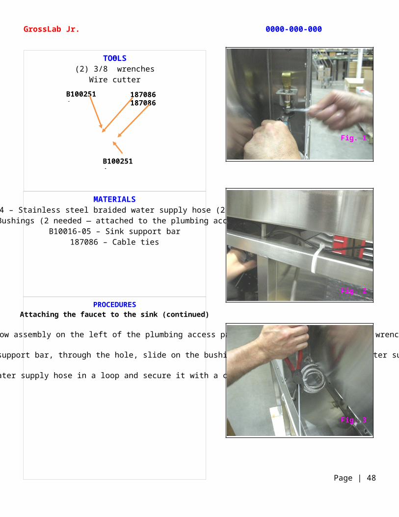
Attach the cold water supply to the cold water elbow assembly on the left of the plumbing access panel and tighten with a pair of wrenches (Fig. 1).
When attaching the hot water hose, feed it over the sink support bar, through the hole, slide on the bushing, and attach it to the hot water supply elbow (Fig. 2).
Roll any excess water supply hose in a loop and secure it with a cable tie (Fig. 3).
TOOLS(2) 3/8” wrenches
Wire cutter
GrossLab Jr. 0000-000-000
Page | 48
187086B1002514 187086
B1002514
Fig. 1
Fig. 3
Fig. 2

MATERIALSB1000473 – Faucet with pull out spray spout
105119 – Lead-free anti-siphon vacuum breaker 1001712 –3/4” rubber hosesBucket
Water supply
PROCEDURESLeak testing the faucet
With the water supply hoses attached, it is time to leak test the system. Attach a pair of black flexible 3/8” water hoses to the bottom of each vacuum breaker (Fig. 1).
Attach the other end of the hoses to a water supply (Fig. 2).
Open the faucet valve to verify that water flows through the system and there are no leaks anywhere in the system (Fig. 3).
Grasp the faucet and move it left and right. Pull out the spray spout and gently push it back. All movements should be swift and smooth (Fig. 4).
TOOLS
GrossLab Jr. 0000-000-000
Page | 49
105119
1001712
1001712B1000473B1000473 Fig. 1
Fig. 3
Fig. 4
Fig. 2
MATERIALSB1001205 – ½ horsepower, 120 V disposal
Plumbing putty
PROCEDURESAttaching the disposal to the sink
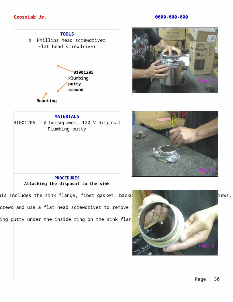
Remove the mounting assembly from the top of the disposal. This includes the sink flange, fiber gasket, backup ring, mounting ring with 3 screws, and snap ring (Fig. 1).
Loosen the 3 mounting screws and use a flat head screwdriver to remove the snap ring (Fig. 2).
Apply plumbing putty under the inside ring on the sink flange (Fig. 3).
TOOLS¼” Phillips head screwdriver
Flat head screwdriver
GrossLab Jr. 0000-000-000
Page | 50
Plumbing putty around ring
B1001205
Mounting assembly
Fig. 1
Fig. 3
Fig. 2
MATERIALSB1001205 – ½ horsepower, 120 V disposal
B10011 – Stainless steel sink
PROCEDURESAttaching the disposal to the sink (continued)
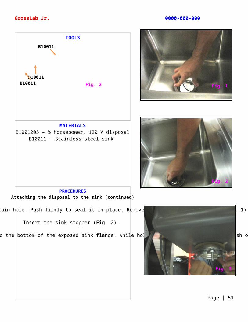
Push the sink flange into the sink drain hole. Push firmly to seal it in place. Remove any excess plumbing putty (Fig. 1).
Insert the sink stopper (Fig. 2).
Working from under the sink, insert the fiber gasket, backup ring, and mounting ring to the bottom of the exposed sink flange. While holding this assembly in place, push on the snap ring until it snaps into place (Fig. 3).
TOOLS
GrossLab Jr. 0000-000-000
Page | 51
Fig. 2B10011
B10011
B10011
Fig. 1
Fig. 2
Fig. 3
MATERIALSB1001205 – ½ horsepower, 120 V disposal
235023 – Line cord stock cable1000696 – Liquid-tight strain-relief connector
PROCEDURESAttaching the disposal to the sink (continued)
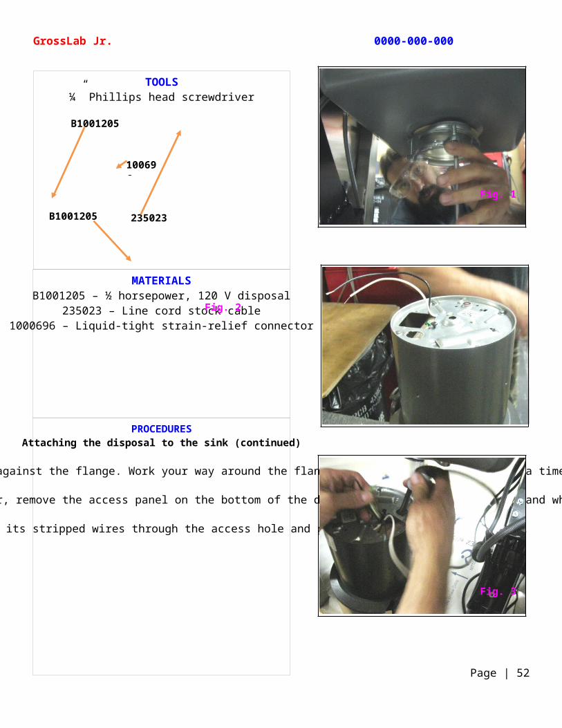
Tighten each of the 3 screws evenly and firmly against the flange. Work your way around the flange tightening each a little at a time (Fig. 1).
Turn the disposal over. Using a Phillips head screwdriver, remove the access panel on the bottom of the disposal and pull out the black and white wires (Fig. 2).
Insert the line cord cable with its stripped wires through the access hole and pull the wires through (Fig. 3).
TOOLS¼” Phillips head screwdriver
GrossLab Jr. 0000-000-000
Page | 52
B1001205
Fig. 2
B1001205
235023
100696
Fig. 1
Fig. 3
MATERIALSB1001205 – 115 volt disposal unit
Downspout for 115 volt disposal unitRetainer bracket
1000696 – Liquid-tight strain-relief connector
PROCEDURESAttaching the disposal to the sink (continued)
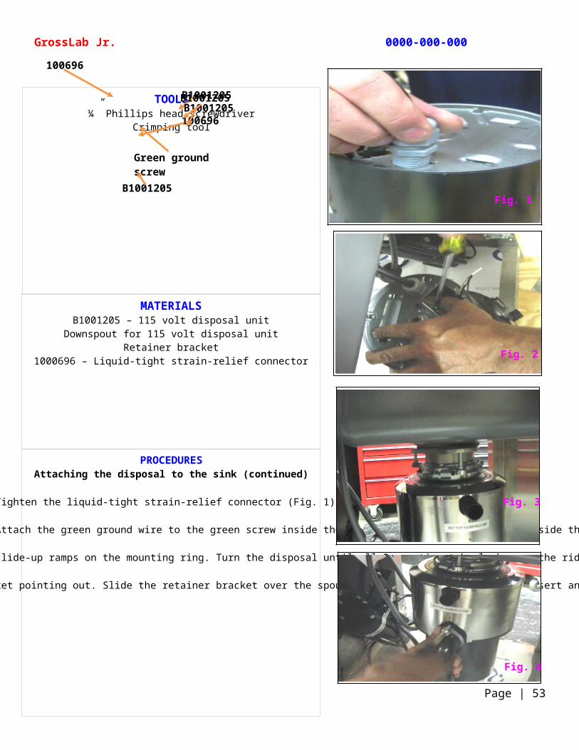
Tighten the liquid-tight strain-relief connector (Fig. 1).
Using closed-end connectors, attach the 2 white wires and the 2 black wires together. Attach the green ground wire to the green screw inside the disposal. Push the wires back inside the disposal and lock the access panel (Fig. 2).
Lift the disposal and line up the 3 mounting tabs on the disposal to the 3 slide-up ramps on the mounting ring. Turn the disposal until all 3 mounting tabs lock over the ridges on the slide-up ramps (Fig. 3).
Install the downspout pointing down with the beveled side on its gasket pointing out. Slide the retainer bracket over the spout, work the tab into the slot, insert and tighten the screw (Fig. 4).
TOOLS¼” Phillips head screwdriver
Crimping tool
GrossLab Jr. 0000-000-000
Page | 53
B1001205
100696
100696
B1001205
Green ground screw
B1001205
B1001205
Fig. 1
Fig. 2
Fig. 3
Fig. 4
MATERIALSB8005479-08 – Base shelf weldment
B8005479-09 – Inner side panel1075061 – ¼ x 20 x 0.50 hex head bolt
PROCEDURESAttaching the base shelf to the elevating stand assembly
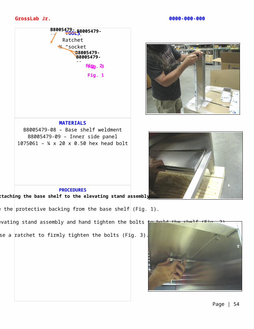
Remove the protective backing from the base shelf (Fig. 1).
Set it in place under the elevating stand assembly and hand tighten the bolts to hold the shelf (Fig. 2).
Use a ratchet to firmly tighten the bolts (Fig. 3).
TOOLSRatchet
¼ “socket
GrossLab Jr. 0000-000-000
Page | 54
Fig. 3Fig. 2
Fig. 1
B8005479-08B8005479-08
B8005479-08B8005479-09
MATERIALSB10011 – Stainless steel sink
5479-26 – Inner door panel5479-27 – Outer door panel
C1001329 – Door mounting hingeC1001330 – Cabinet mount hinge
Hinge assembly – C1001329 + C1001330C1003574 – ¼-20 x 1.25 Phillips FHMS
B1001205 – 115 volt disposal unit
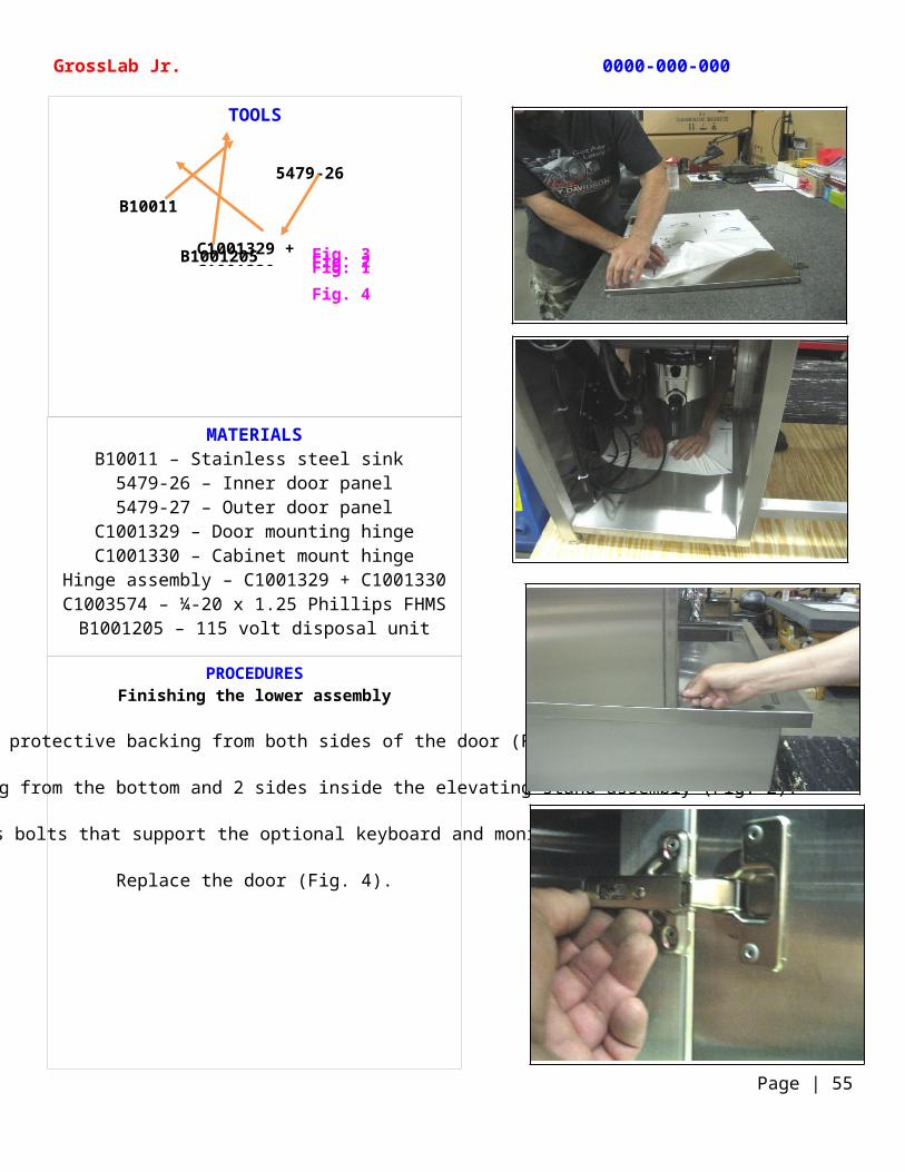
PROCEDURESFinishing the lower assembly
Remove the protective backing from both sides of the door (Fig. 1).
Remove the protective backing from the bottom and 2 sides inside the elevating stand assembly (Fig. 2).
Hand tighten the Phillips bolts that support the optional keyboard and monitor bracket (Fig. 3).
Replace the door (Fig. 4).
TOOLS
GrossLab Jr. 0000-000-000
Page | 55
Fig. 1Fig. 2Fig. 3
Fig. 4
5479-26
B1001205
B10011
C1001329 + C1001330
MATERIALSB8005479-05 – Façade weldment1000785 –Thermo Scientific decal
Elevate decalDisposal decalExhaust decalPower decal
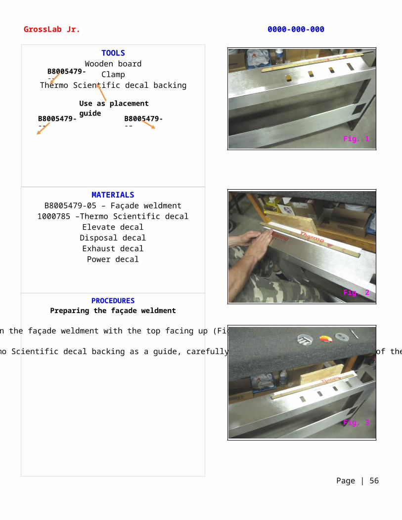
PROCEDURESPreparing the façade weldment
Position the façade weldment with the top facing up (Fig. 1).
Clamp a wooden board to the back of the façade and using the Thermo Scientific decal backing as a guide, carefully place the decals on the front of the facade (Fig. 2 and Fig. 3).
TOOLSWooden board
ClampThermo Scientific decal backing
GrossLab Jr. 0000-000-000
Page | 56
B8005479-05
Use as placement guide
B8005479-05 B8005479-05
Fig. 1
Fig. 2
Fig. 3
MATERIALSB8005479-05 – Façade weldment
B1001245 – Outside panel 1001152 – M6-1.0 x 10 button head socket
10634 – Upper shelf
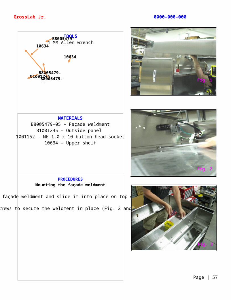
PROCEDURESMounting the façade weldment
Carefully lift the façade weldment and slide it into place on top of the unit (Fig. 1).
Add screws to secure the weldment in place (Fig. 2 and Fig. 3).
TOOLS4 MM Allen wrench
GrossLab Jr. 0000-000-000
Page | 57
B8005479-05
10634
B1001245
10634
B8005479-05B8005479-05
Fig. 1
Fig. 2
Fig. 3
MATERIALS10622 – Power assembly wiring harness
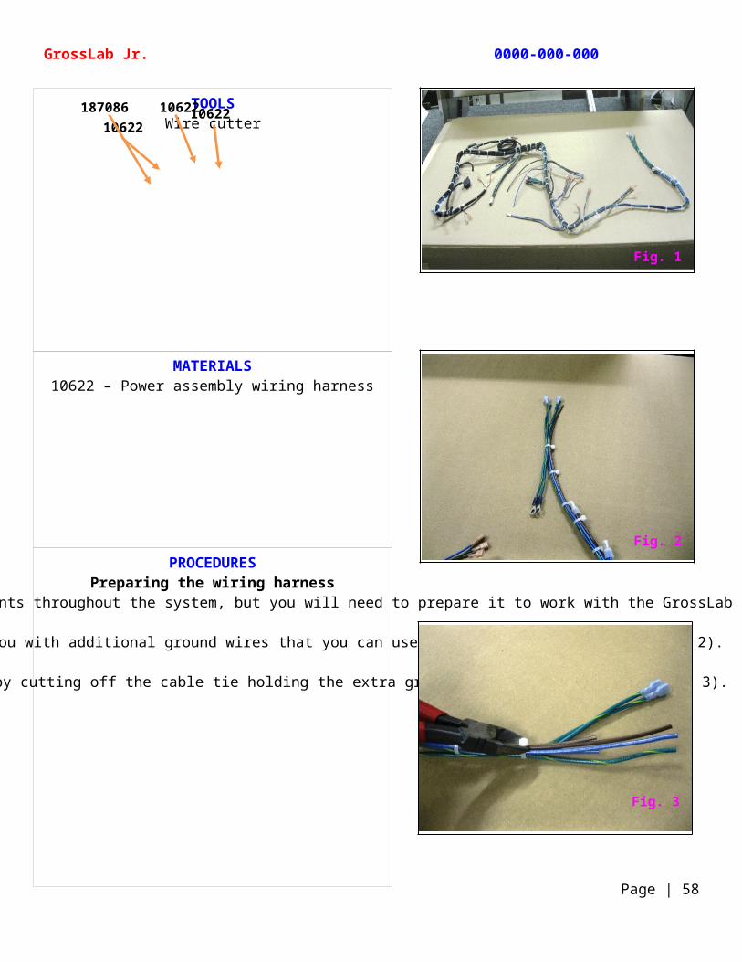
PROCEDURESPreparing the wiring harness
The wiring harness connects the various electronic components throughout the system, but you will need to prepare it to work with the GrossLab Jr. assembly (Fig. 1).
The wiring harness also supplies you with additional ground wires that you can use for different variations (Fig. 2).
Working from right to left, start by cutting off the cable tie holding the extra ground wires to the harness (Fig. 3).
TOOLSWire cutter
GrossLab Jr. 0000-000-000
Page | 58
1062210622
10622187086
Fig. 1
Fig. 2
Fig. 3
MATERIALS
10622 – Power assembly wiring harnessB23213 –Receptacle outlet
106202 – Junction box1000696 – Liquid-tight strain relief connector
1000665 – Flanged terminal connectors
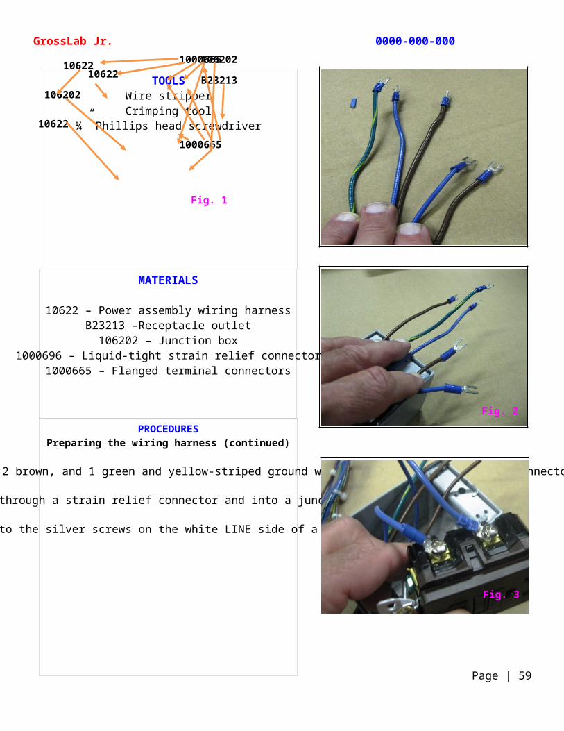
PROCEDURESPreparing the wiring harness (continued)
Remove about 2” of the insulation at the end of the 2 blue, 2 brown, and 1 green and yellow-striped ground wire and add flanged terminal connectors to each end (Fig. 1).
Feed the 5 wires through a strain relief connector and into a junction box (Fig. 2).
Connect the 2 blue wires to the silver screws on the white LINE side of a receptacle outlet (Fig. 3).
TOOLSWire stripperCrimping tool
¼” Phillips head screwdriver
GrossLab Jr. 0000-000-000
Page | 59
Fig. 1
10622
10622
106202
106202
1000665
10622B23213
1000665
Fig. 2
Fig. 3
MATERIALS10622 – Power assembly wiring harness
B23213 –Receptacle outlet106202 – Junction box
1000696 – Liquid-tight strain relief connector1000665 – Flanged terminal connectors
B10128 – GFCI receptacle mounting
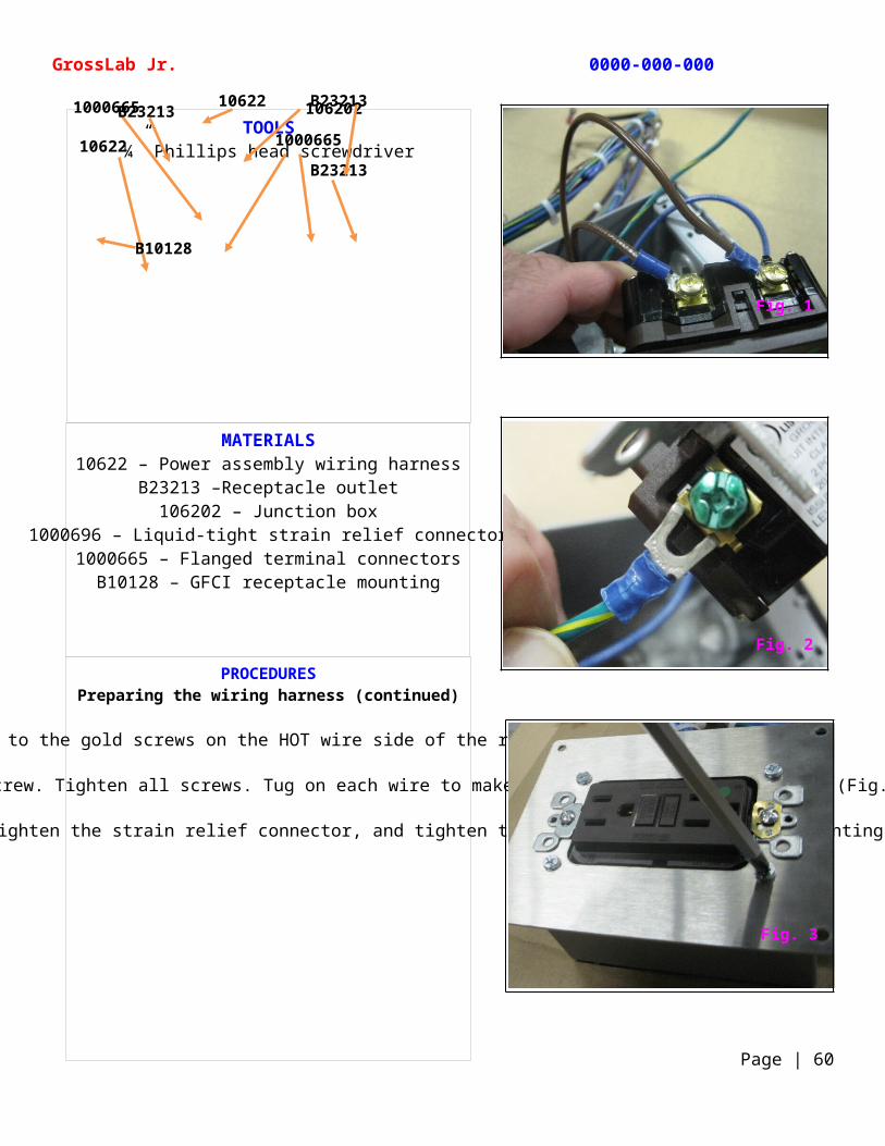
PROCEDURESPreparing the wiring harness (continued)
Attach the 2 brown wires to the gold screws on the HOT wire side of the receptacle outlet (Fig. 1).
Connect the ground wire to the green screw. Tighten all screws. Tug on each wire to make sure the connections are firm (Fig. 2).
Push the receptacle into the junction box, hand tighten the strain relief connector, and tighten the screws on the receptacle mounting plate (Fig. 3).
TOOLS¼” Phillips head screwdriver
GrossLab Jr. 0000-000-000
Page | 60
10622 106202
1000665
B23213
1000665 B23213
10622
B23213
B10128
Fig. 1
Fig. 2
Fig. 3
MATERIALS10622 – Power assembly wiring harness
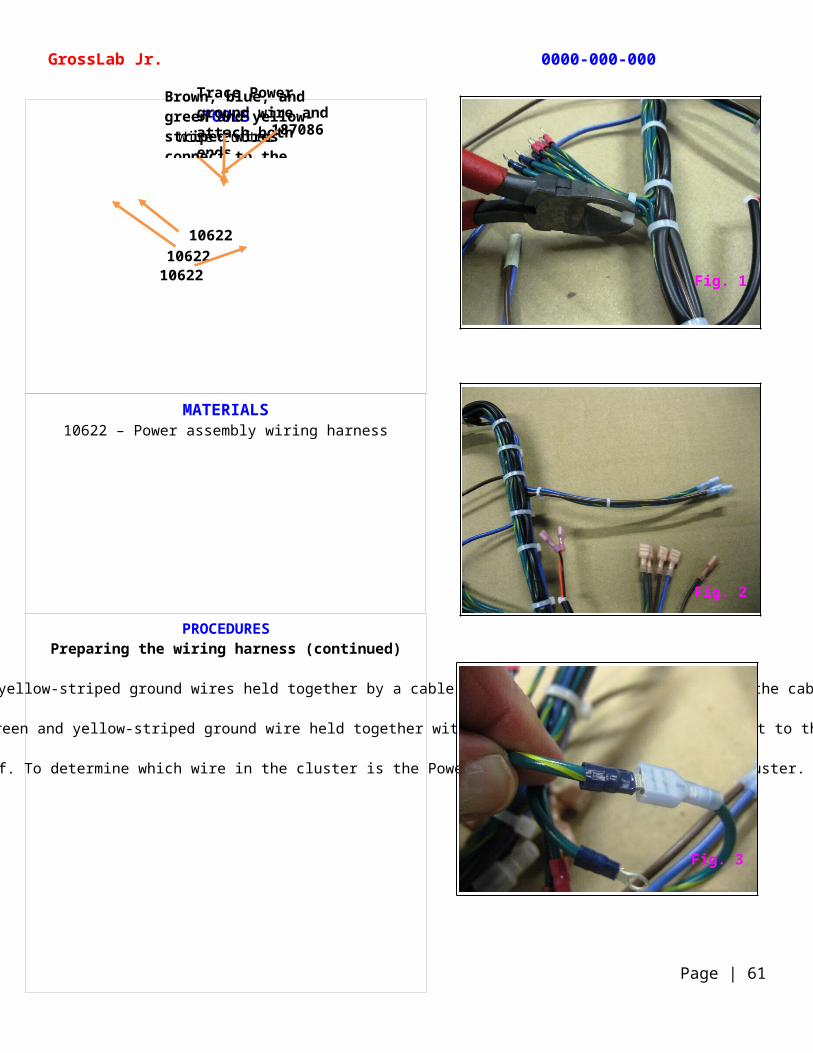
PROCEDURESPreparing the wiring harness (continued)
As you move down the harness, you will notice 8 green and yellow-striped ground wires held together by a cable tie. Using wire cutters, cut off the cable tie (Fig. 1).
Across from the cluster of ground wires you will see a brown, blue, and green and yellow-striped ground wire held together with 2 cable ties. These wires connect to the Power IEC connector (Fig. 2).
The Power ground wire should be the first in the cluster of ground wire attached to the grounding stud in the upper shelf. To determine which wire in the cluster is the Power ground wire, trace it to the cluster. Once found, attach the ring terminal end to its blue female connector (Fig. 3).
TOOLSWire cutter
GrossLab Jr. 0000-000-000
Page | 61
Brown, blue, and green and yellow-striped wires connect to the Power IEC connector
Trace Power ground wire and attach both ends
1062210622
10622
187086
Fig. 1
Fig. 2
Fig. 3
MATERIALS10622 – Power assembly wiring harness
B23213 –Receptacle outlet106202 – Junction box
1000696 – Liquid-tight strain relief connector1000665 – Flanged terminal connectors
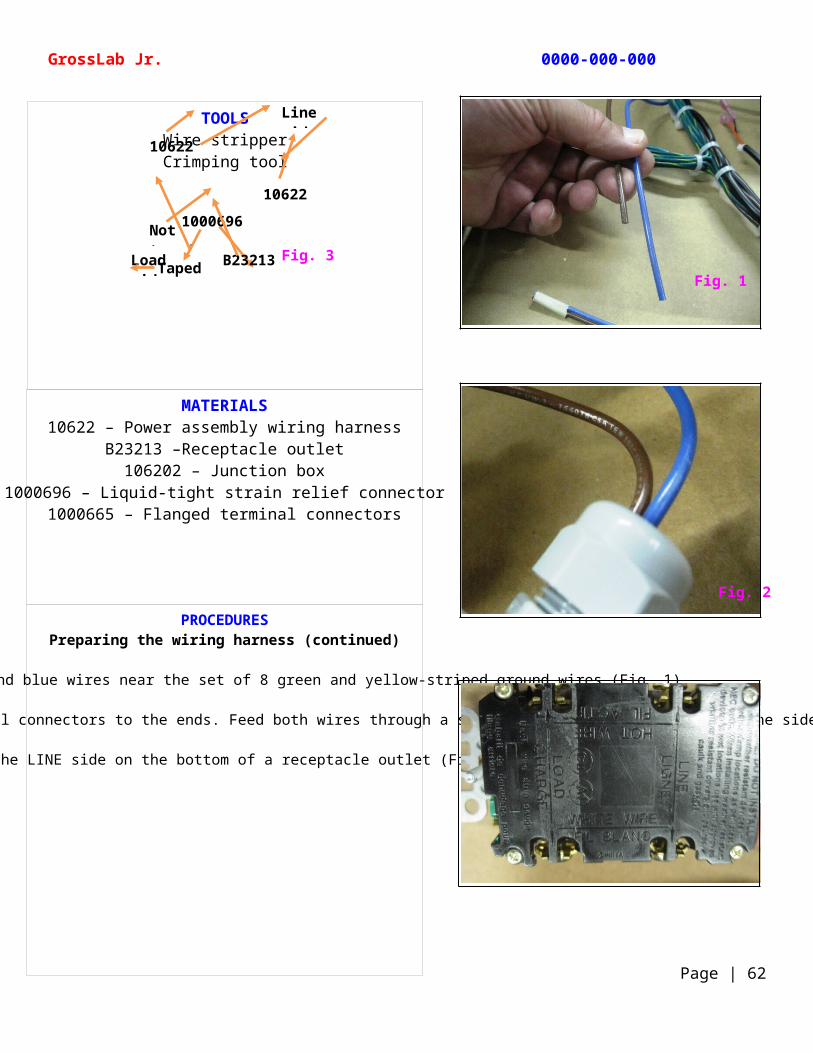
PROCEDURESPreparing the wiring harness (continued)
Locate the non-taped brown and blue wires near the set of 8 green and yellow-striped ground wires (Fig. 1).
Remove about 2” of insulation from each wire and attach flanged terminal connectors to the ends. Feed both wires through a strain relief connector and into one side of a junction box (Fig. 2).
Locate the LINE side on the bottom of a receptacle outlet (Fig. 3).
TOOLSWire stripperCrimping tool
GrossLab Jr. 0000-000-000
Page | 62
Fig. 3
Line side
Load side
10622
Not taped
Taped
1000696
B23213
10622
Fig. 1
Fig. 2
MATERIALS10622 – Power assembly wiring harness
B23213 –Receptacle outlet106202 – Junction box
1000696 – Liquid-tight strain relief connector1000665 – Flanged terminal connectors
PROCEDURESPreparing the wiring harness (continued)
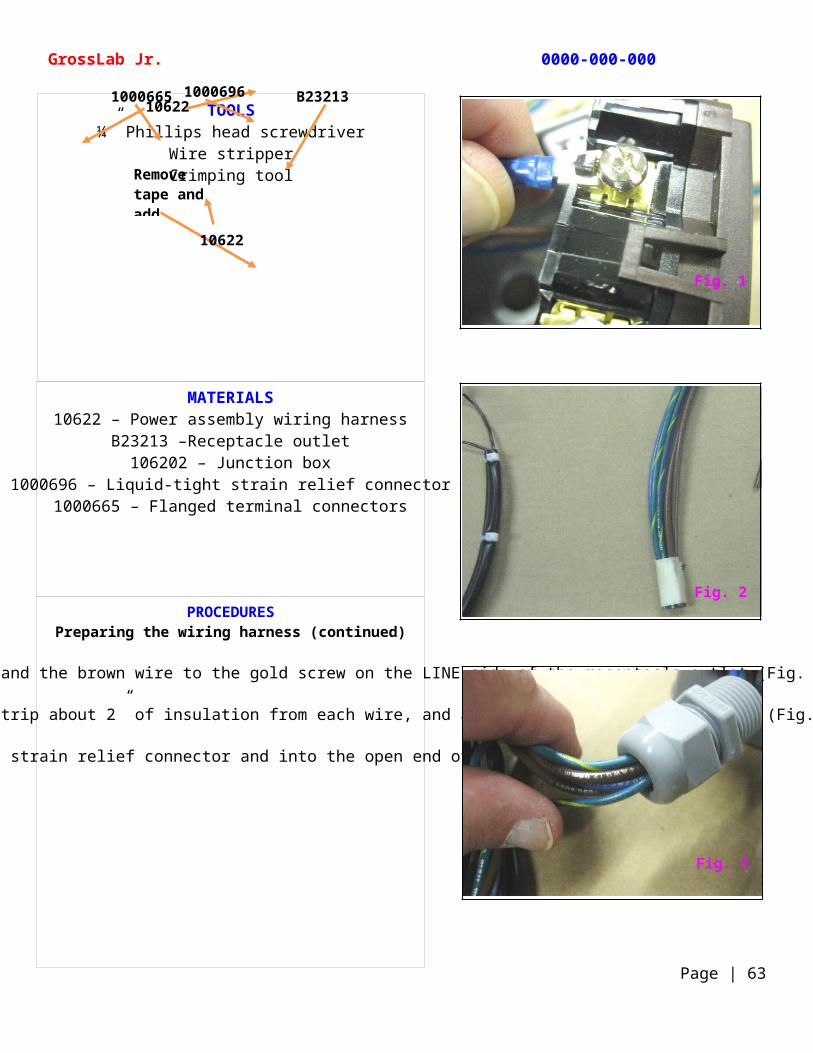
Attach the blue wire to the silver screw and the brown wire to the gold screw on the LINE side of the receptacle outlet (Fig. 1).
Remove the tape from the set of 6 wires, strip about 2” of insulation from each wire, and add flanged terminal connectors (Fig. 2).
Feed the 6 wires through the strain relief connector and into the open end of the junction box (Fig. 3).
TOOLS¼” Phillips head screwdriver
Wire stripperCrimping tool
GrossLab Jr. 0000-000-000
Page | 63
B23213100066510622
Remove tape and add 1000665
1000696
10622
Fig. 1
Fig. 2
Fig. 3
MATERIALS10622 – Power assembly wiring harness
B23213 –Receptacle outlet106202 – Junction box
1000696 – Liquid-tight strain relief connector1000665 – Flanged terminal connectors
B10128 – GFCI receptacle mounting 1001269 – Double-sided tape
PROCEDURESPreparing the wiring harness (continued)
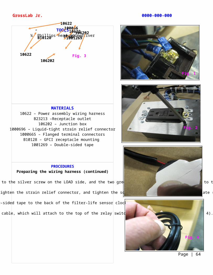
Piggyback the 2 brown wires to the gold screw on the LOAD side, the 2 blue wires to the silver screw on the LOAD side, and the two green and yellow-striped ground wires to the green screw on the LOAD side (Fig. 1).
Fit the receptacle into the junction box, hand tighten the strain relief connector, and tighten the screws on the receptacle mounting plate (Fig. 2).
Apply double-sided tape to the back of the filter-life sensor clock (Fig. 3).
Remove the 2 twist ties from the wound cable, which will attach to the top of the relay switch mounted to the upper shelf (Fig. 4).
TOOLS¼” Phillips head screwdriver
GrossLab Jr. 0000-000-000
Page | 64
Fig. 3
106221000665
106202
106202
10622B10128 100126910622
10622
Fig. 1
Fig. 2
Fig. 4
MATERIALS10655 – Florescent light fixture panel
109269 – Lamp holder
PROCEDURESInstalling the ballast to the florescent light fixture
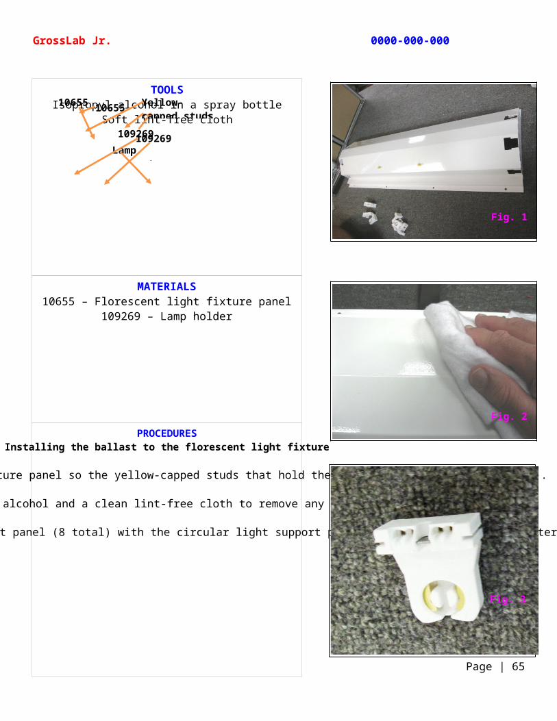
Position the florescent light fixture panel so the yellow-capped studs that hold the ballast are facing you (Fig. 1).
Wipe the light panel down with alcohol and a clean lint-free cloth to remove any dirt or other debris (Fig. 2).
Next, you will install 4 lamp holders into each end of the light panel (8 total) with the circular light support pointing down and toward the center of the light panel (Fig. 3).
TOOLSIsopropyl alcohol in a spray bottle
Soft lint-free cloth
GrossLab Jr. 0000-000-000
Page | 65
Lamp support109269109269
Yellow-capped studs1065510655
Fig. 1
Fig. 2
Fig. 3
MATERIALS10655 – Florescent light fixture panel
109269 – Lamp holder
PROCEDURESInstalling the ballast to the florescent light fixture (continued)
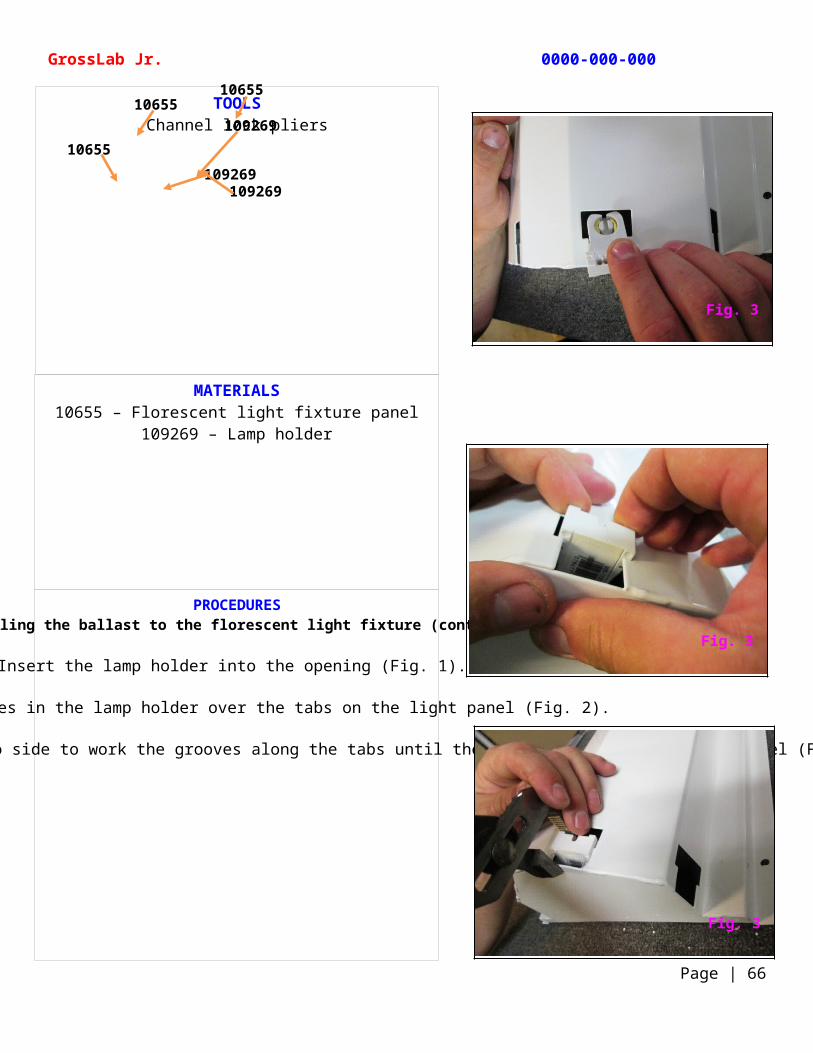
Insert the lamp holder into the opening (Fig. 1).
Slide the grooves in the lamp holder over the tabs on the light panel (Fig. 2).
Using channel lock pliers move from side to side to work the grooves along the tabs until they are flush with the light panel (Fig. 3).
TOOLSChannel lock pliers
GrossLab Jr. 0000-000-000
Page | 66
10926910655
109269109269
10655
10655
Fig. 3
Fig. 3
Fig. 3
MATERIALS10655 – Florescent light fixture panel
1000300 – Advance R-2S40TPM ballast1001144 – M6-1 hex nut
1001145 – M6 lock washer
PROCEDURESInstalling the ballast to the florescent light fixture (continued)
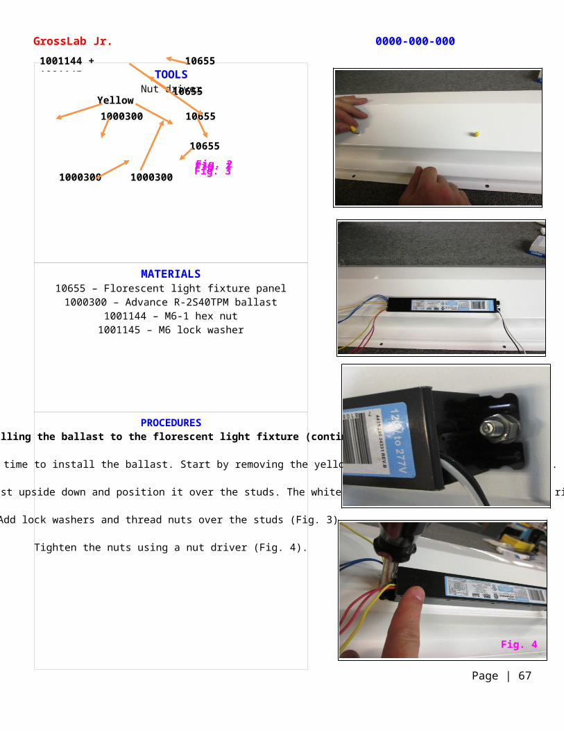
With all 8 lamp holders installed, it is time to install the ballast. Start by removing the yellow plastic caps from the studs (Fig. 1).
Unwrap and separate the wires leading from the ballast and with the studs facing you, turn the ballast upside down and position it over the studs. The white and black wires should be on your right and the blue, yellow, and red wires on your left (Fig. 2).
Add lock washers and thread nuts over the studs (Fig. 3).
Tighten the nuts using a nut driver (Fig. 4).
TOOLSNut driver
GrossLab Jr. 0000-000-000
Page | 67
Fig. 3Fig. 2Fig. 1
Yellow caps
10655
10655
10655
10655
1000300
1000300 1000300
1001144 + 1001145
Fig. 4
MATERIALS10655 – Florescent light fixture panel
1000300 – Advance R-2S40TPM ballast107574 – Tie anchors
PROCEDURESInstalling the ballast to the florescent light fixture (continued)
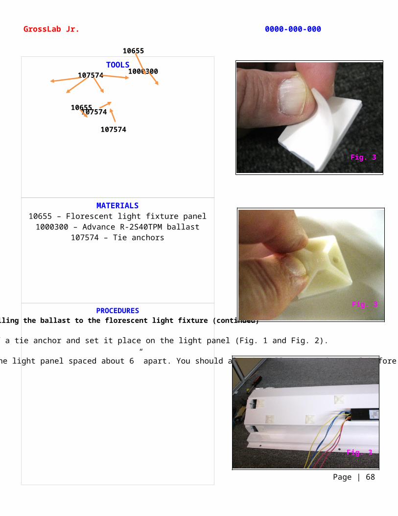
Peel the backing off a tie anchor and set it place on the light panel (Fig. 1 and Fig. 2).
Generally, you should add a tie anchor along the creases in the light panel spaced about 6” apart. You should also install one on the panel before each lamp holder (Fig. 3).
TOOLS
GrossLab Jr. 0000-000-000
Page | 68
107574
10655
107574
107574
10655
1000300
Fig. 3
Fig. 3
Fig. 3
MATERIALS10655 – Florescent light fixture panel
1000300 – Advance R-2S40TPM ballast109269 – Lamp holder107574 – Tie anchors187086 – Cable ties
PROCEDURESInstalling the ballast to the florescent light fixture (continued)
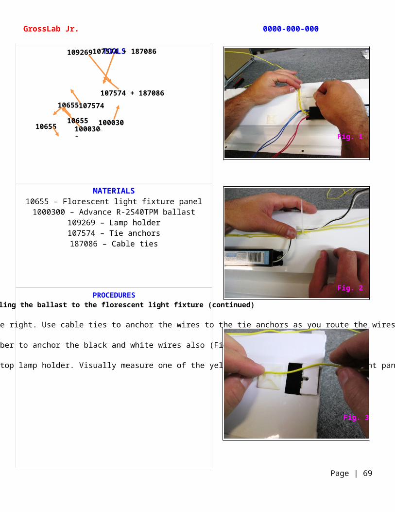
Route the ballast’s 2 yellow wires up and to the right. Use cable ties to anchor the wires to the tie anchors as you route the wires (Fig. 1).
Remember to anchor the black and white wires also (Fig. 2).
Route one yellow wire to the rear top lamp holder and the other to the front top lamp holder. Visually measure one of the yellow wires to the end of the light panel leaving a little extra slack (Fig. 3).
TOOLS
GrossLab Jr. 0000-000-000
Page | 69
10655
1000300
107574 + 187086
107574 + 187086
10655 100030010655
109269
107574
Fig. 1
Fig. 2
Fig. 3
MATERIALS10655 – Florescent light fixture panel
109269 – Lamp holder
PROCEDURESInstalling the ballast to the florescent light fixture (continued)
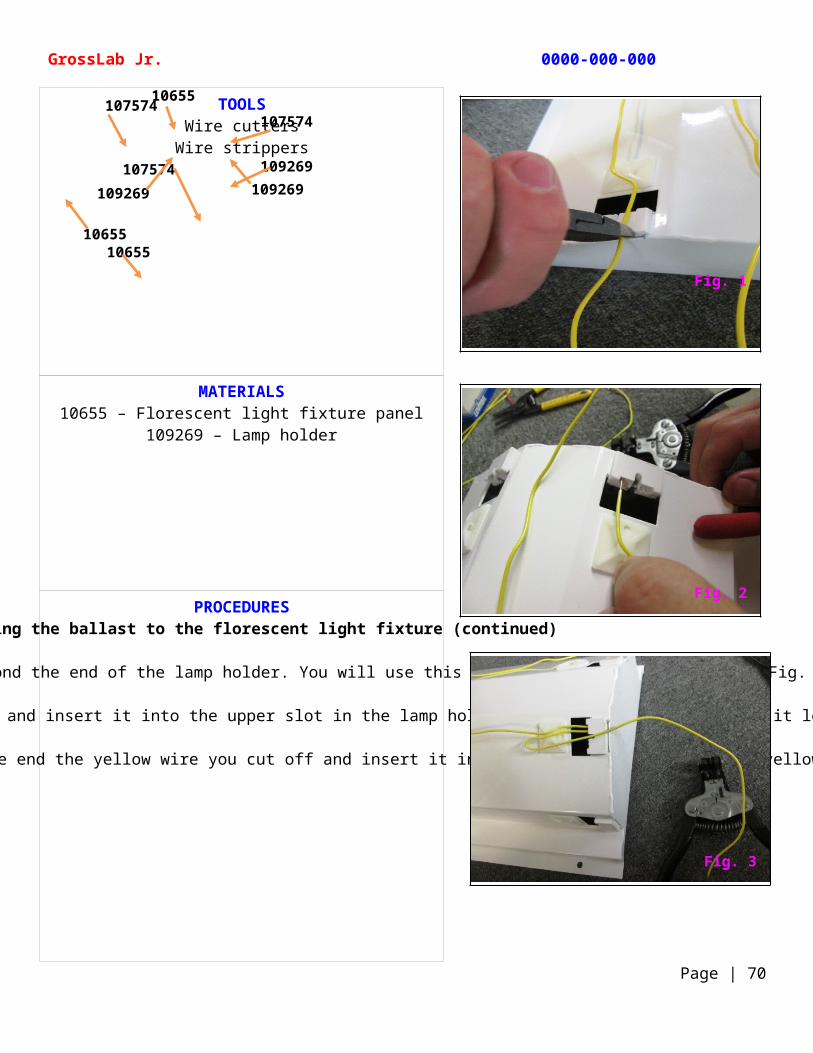
Cut off the excess wire extending beyond the end of the lamp holder. You will use this section to make a jumper wire (Fig. 1).
Strip about ¼” of insulation from the end of the yellow wire and insert it into the upper slot in the lamp holder. Tug the wire to make sure it locked into place (Fig. 2).
To make a jumper wire, strip the insulation off one end the yellow wire you cut off and insert it into the slot next to the first yellow wire (Fig. 3).
TOOLSWire cutters
Wire strippers
GrossLab Jr. 0000-000-000
Page | 70
107574107574
107574 109269109269109269
10655
1065510655
Fig. 1
Fig. 2
Fig. 3
MATERIALS10655 – Florescent light fixture panel
109269 – Lamp holder107574 – Tie anchors
PROCEDURESInstalling the ballast to the florescent light fixture (continued)
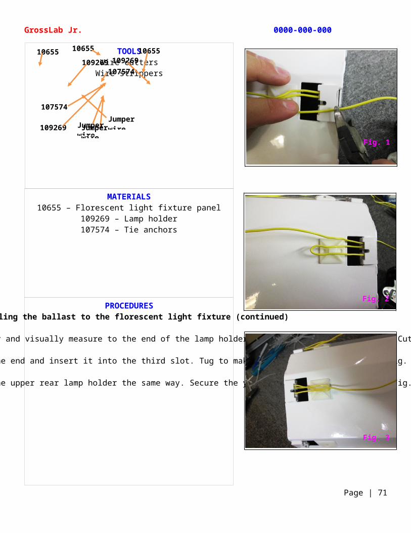
Hold the section of yellow wire slightly beyond the tie anchor and visually measure to the end of the lamp holder leaving a little extra slack. Cut off the excess wire (Fig. 1).
Strip about ¼” of insulation off the end and insert it into the third slot. Tug to make sure it locked into place (Fig. 2).
Install the second yellow wire to the upper rear lamp holder the same way. Secure the yellow wires using cable ties (Fig. 3).
TOOLSWire cutters
Wire strippers
GrossLab Jr. 0000-000-000
Page | 71
Jumper wire
10655
109269
10655 10655109269 109269
Jumper wire
Jumper wire
107574
107574
Fig. 1
Fig. 2
Fig. 3
MATERIALS10655 – Florescent light fixture panel
1000300 – Advance R-2S40TPM ballast109269 – Lamp holder107574 – Tie anchors187086 – Cable ties
PROCEDURESInstalling the ballast to the florescent light fixture (continued)
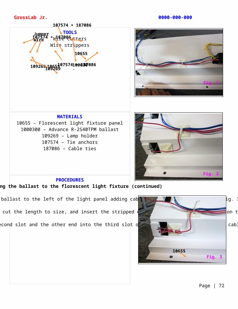
Route the red and blue wires from the ballast to the left of the light panel adding cable ties as you along the way (Fig. 1).
Route one red wire to the bottom left of the lamp holder, measure, cut the length to size, and insert the stripped end into the lowest bottom slot on the bottom lamp holder (Fig. 2).
Use the cut off section to make a jumper and insert one end into the second slot and the other end into the third slot on the bottom lamp holder. Add a cable tie to secure the wires (Fig. 3).
TOOLSWire cutters
Wire strippers
GrossLab Jr. 0000-000-000
Page | 72
107574 + 187086
10655
10655 1000300
107574 + 187086
107574 + 187086
Jumper wire
109269109269
Fig. 1
Fig. 2
Fig. 310655
MATERIALS10655 – Florescent light fixture panel
1000300 – Advance R-2S40TPM ballast109269 – Lamp holder107574 – Tie anchors187086 – Cable ties
PROCEDURESInstalling the ballast to the florescent light fixture (continued)
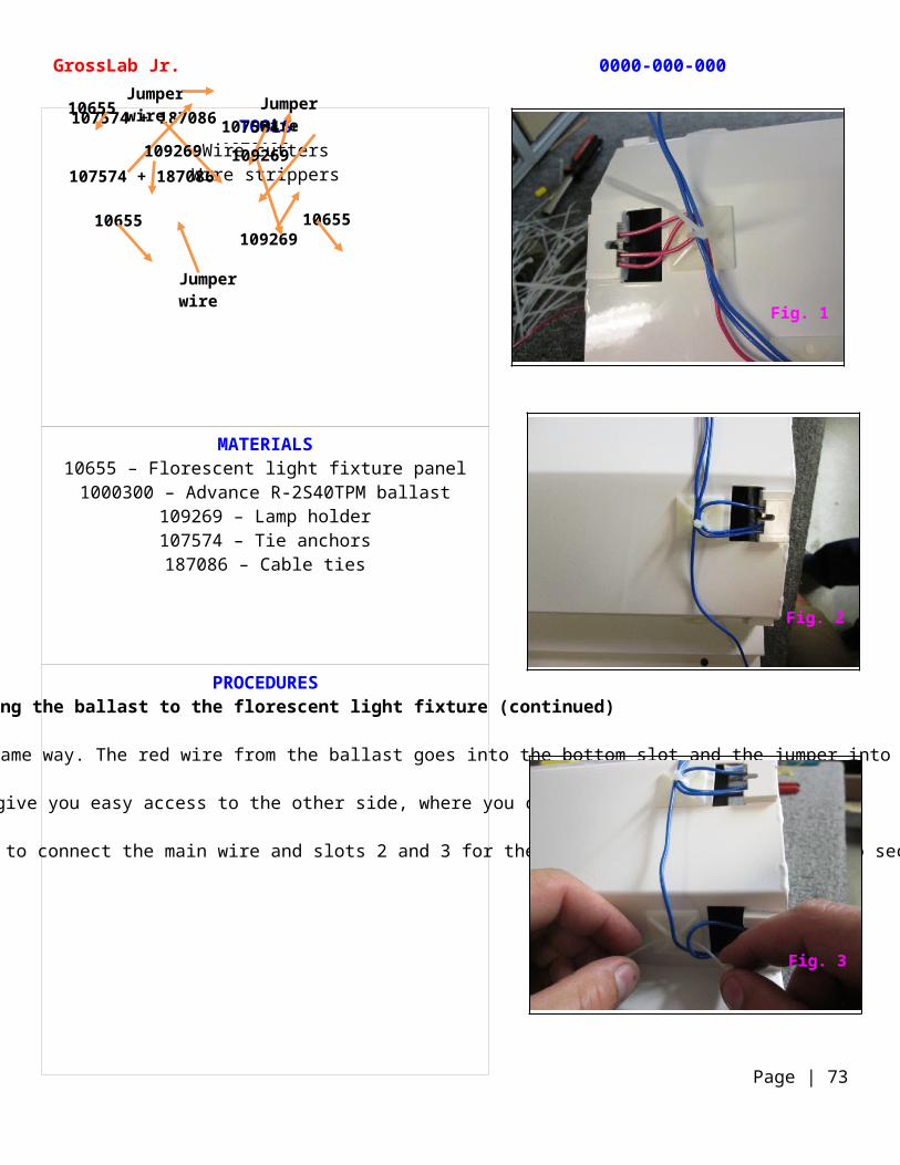
Insert the second red wire into the upper lamp holder the same way. The red wire from the ballast goes into the bottom slot and the jumper into slots 2 and 3 (Fig. 1).
Turn the light panel around to give you easy access to the other side, where you connect the blue wires (Fig. 2).
Connect the blue wires the same way using the bottom slot to connect the main wire and slots 2 and 3 for the jumper wire. Use cable ties to secure the wires (Fig. 3).
TOOLSWire cutters
Wire strippers
GrossLab Jr. 0000-000-000
Page | 73
107574 + 1070195
Jumper wire Jumper
wire
Jumper wire
107574 + 187086
107574 + 187086
1065510655
10655
109269
109269
109269
Fig. 1
Fig. 2
Fig. 3
MATERIALS10655 – Florescent light fixture panel
1000300 – Advance R-2S40TPM ballast109269 – Lamp holder107574 – Tie anchors187086 – Cable ties
PROCEDURESInstalling the ballast to the florescent light fixture (continued)
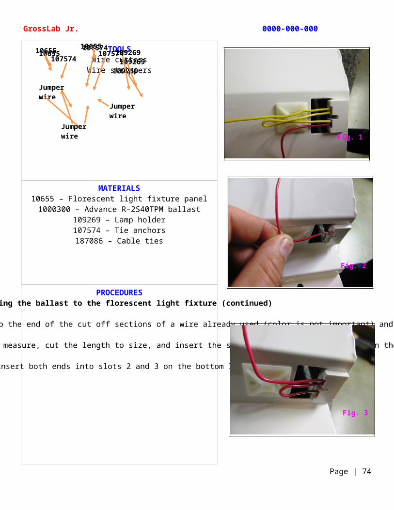
Now on the yellow wire side of the light panel, you will use jumper wires to power the 2 bottom lamp holders. Strip the end of the cut off sections of a wire already used (color is not important) and insert it into the bottom slot on one of the yellow-wired lamp holders (Fig. 1).
Route the other end to the bottom lamp holder on the same side, measure, cut the length to size, and insert the stripped end into the top slot on the bottom lamp holder (Fig. 2).
Make a jumper and insert both ends into slots 2 and 3 on the bottom lamp holder (Fig. 3).
TOOLSWire cutters
Wire strippers
GrossLab Jr. 0000-000-000
Page | 74
10655 107574
109269109269
109269107574107574
10655 10655
Jumper wire
Jumper wire
Jumper wire Fig. 1
Fig. 2
Fig. 3
MATERIALS10655 – Florescent light fixture panel
1000300 – Advance R-2S40TPM ballast1001508 – 36” florescent lamps (4 needed)
109269 – Lamp holder107574 – Tie anchors187086 – Cable ties
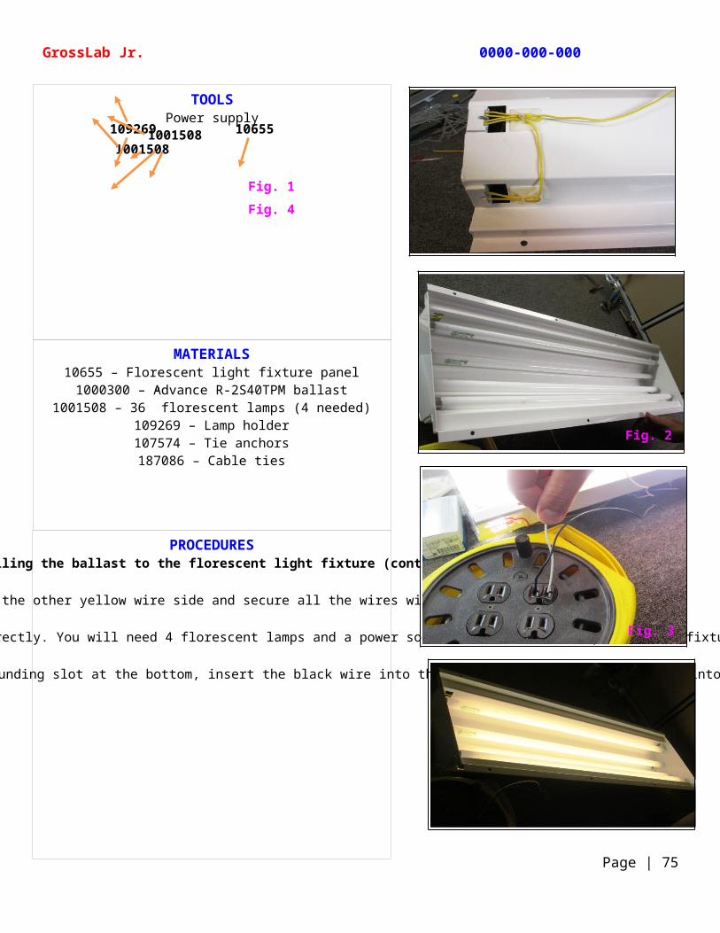
PROCEDURESInstalling the ballast to the florescent light fixture (continued)
Repeat the process for the other yellow wire side and secure all the wires with cable ties (Fig. 1).
Now you want to verify that the wiring is done correctly. You will need 4 florescent lamps and a power source. Insert the 4 lamps into the fixture (Fig. 2).
Insert the stripped ends of the black and white wires from the ballast into power outlet. With the grounding slot at the bottom, insert the black wire into the left socket and the white wire into the right socket. The fixture should light. (Fig. 3 and Fig. 4).
TOOLSPower supply
GrossLab Jr. 0000-000-000
Page | 75
Fig. 1
Fig. 4
109269 106551001508
1001508
Fig. 2
Fig. 3
MATERIALS10622 – Power assembly wiring harness
B8005479-05 – Façade weldment10634 – Upper shelf
106202 – Junction box108355 – #8-32 x 0.375 Phillips pan head screw
236000 – #8-32 hex nut
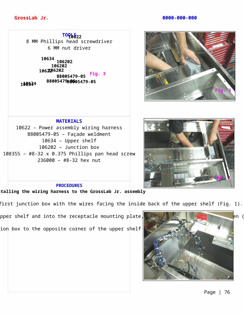
PROCEDURESInstalling the wiring harness to the GrossLab Jr. assembly
To install the harness, position the first junction box with the wires facing the inside back of the upper shelf (Fig. 1).
Feed the screws up through the bottom of the upper shelf and into the receptacle mounting plate, thread on a hex nut, and tighten (Fig. 2).
Install the second junction box to the opposite corner of the upper shelf the same way (Fig. 3).
TOOLS8 MM Phillips head screwdriver
6 MM nut driver
GrossLab Jr. 0000-000-000
Page | 76
Fig. 3106202
10634 B8005479-05B8005479-05
10634 106202
10622
10622
10634 B8005479-05
106202
Fig. 3
Fig. 3
MATERIALS10655 – Florescent light fixture panel
1001508 – 36” florescent lamps (4 needed)1000300 – Advance R-2S40TPM ballast10622 – Power assembly wiring harness
B8005479-05 – Façade weldment10634 – Upper shelf
1001144 – M6-1 hex nut1001145 – M6 lock washer
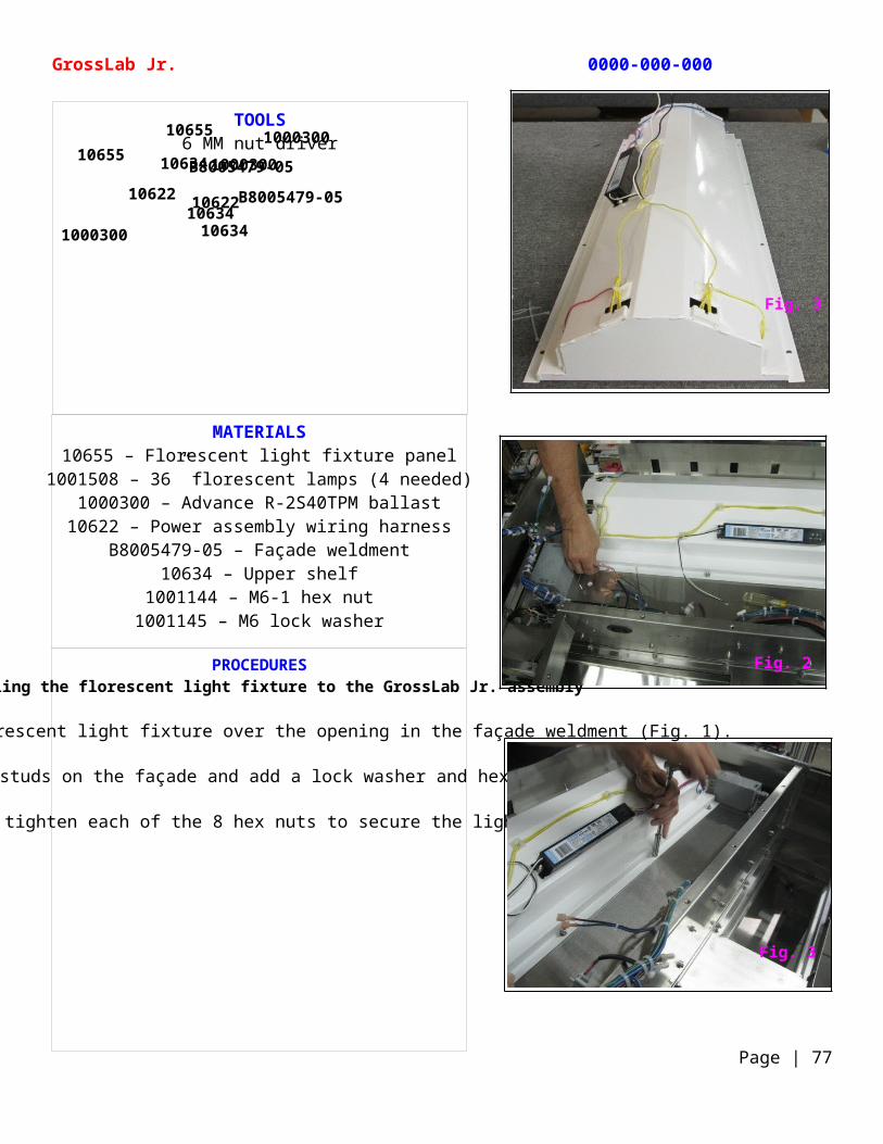
PROCEDURESInstalling the florescent light fixture to the GrossLab Jr. assembly
Next, install the florescent light fixture over the opening in the façade weldment (Fig. 1).
Mount the fixture onto the studs on the façade and add a lock washer and hex nut to each stud (Fig. 2).
Using a nut driver tighten each of the 8 hex nuts to secure the light fixture (Fig. 3).
TOOLS6 MM nut driver
GrossLab Jr. 0000-000-000
Page | 77
10655 100030010634
B8005479-0510622
10655
1000300
B8005479-0510622
1063410634
1000300
Fig. 2
Fig. 3
Fig. 3
MATERIALS10622 – Power assembly wiring harness
B8005479-05 – Façade weldment10634 – Upper shelfUCB control board
1901059 – ¼” nylon spacer (4 needed)236145 – 6-32 nut (4 needed)
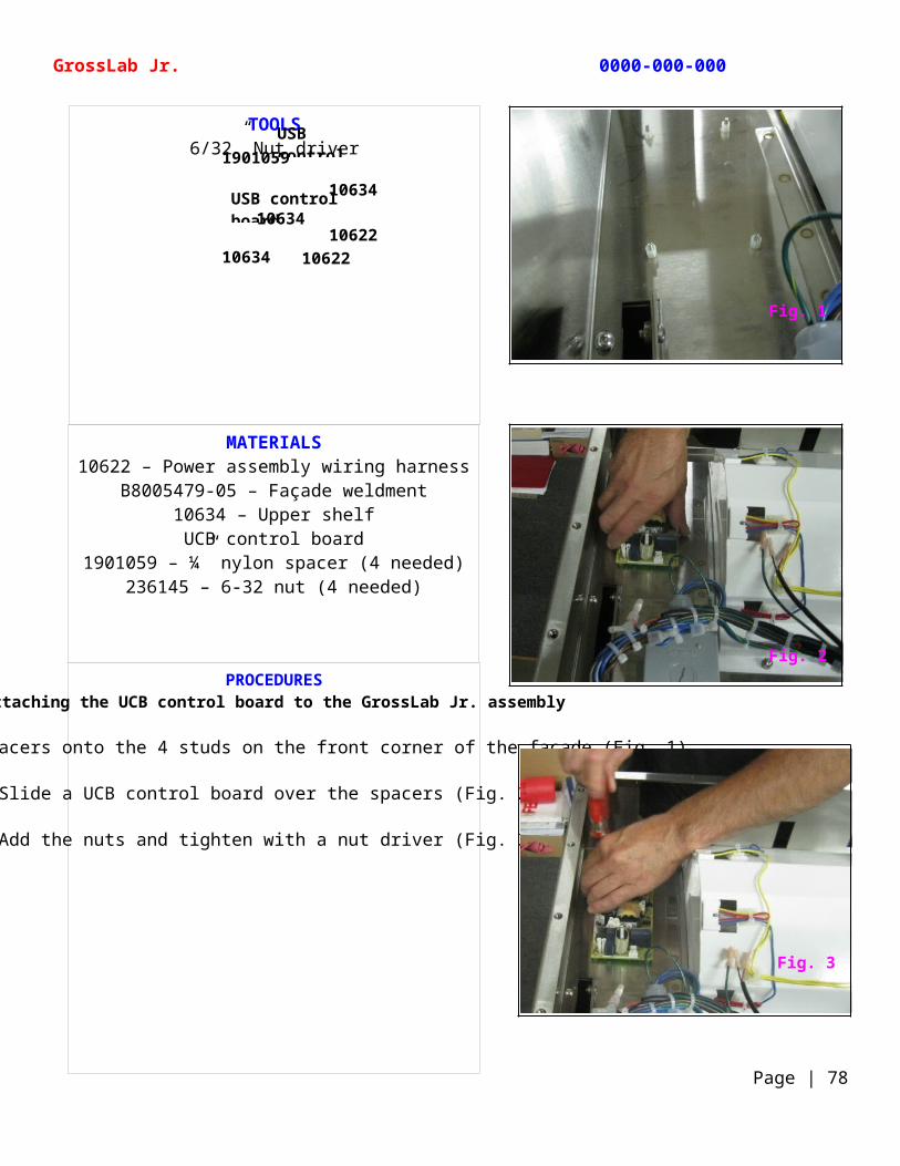
PROCEDURESAttaching the UCB control board to the GrossLab Jr. assembly
Slide the 4 spacers onto the 4 studs on the front corner of the façade (Fig. 1).
Slide a UCB control board over the spacers (Fig. 2).
Add the nuts and tighten with a nut driver (Fig. 3).
TOOLS6/32” Nut driver
GrossLab Jr. 0000-000-000
Page | 78
1901059
10634
USB control board
10622
10634USB control board
10622
10634
Fig. 1
Fig. 2
Fig. 3
MATERIALS10622 – Power assembly wiring harness
1001760 – AC filterB8005479-05 – Façade weldment
10634 – Upper shelf
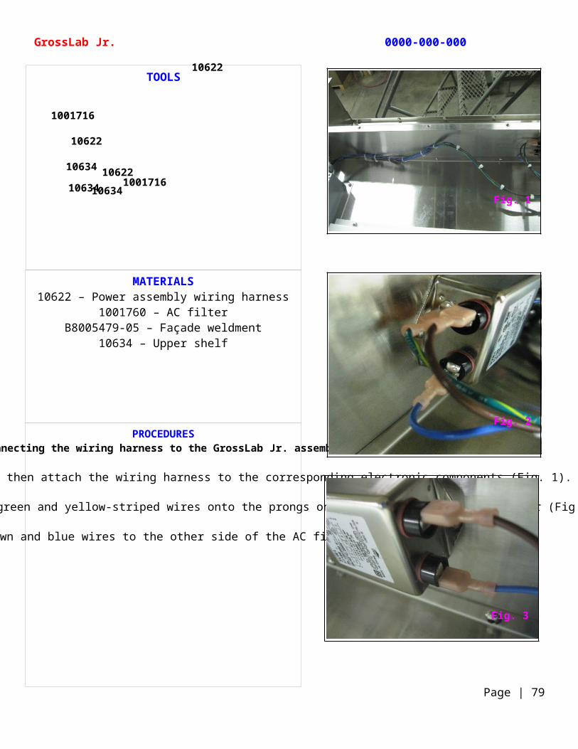
PROCEDURESConnecting the wiring harness to the GrossLab Jr. assembly
Working from left to right, you will then attach the wiring harness to the corresponding electronic components (Fig. 1).
Attach the first set of brown, blue, and green and yellow-striped wires onto the prongs on the left side of the AC filter (Fig. 2).
Attach the brown and blue wires to the other side of the AC filter (Fig. 3).
TOOLS
GrossLab Jr. 0000-000-000
Page | 79
10622
10634
10634
10622
1001716
10634
10622
1001716
Fig. 1
Fig. 2
Fig. 3
MATERIALS10622 – Power assembly wiring harness
B8005479-05 – Façade weldment10634 – Upper shelf
Mounting screwsLocking nuts
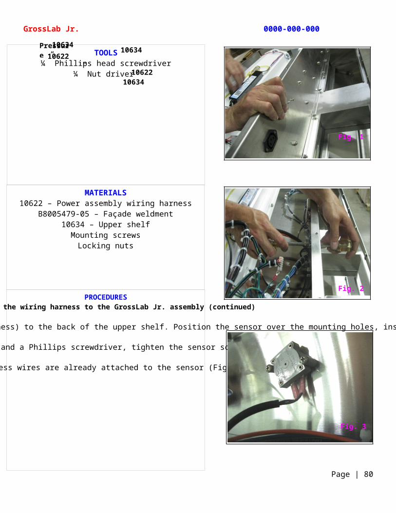
PROCEDURESConnecting the wiring harness to the GrossLab Jr. assembly (continued)
You will now need to attach the gray pressure sensor (which is part of the wiring harness) to the back of the upper shelf. Position the sensor over the mounting holes, insert the screws, and add locking nuts (Fig. 1).
Using a nut driver and a Phillips screwdriver, tighten the sensor screws (Fig. 2).
The harness wires are already attached to the sensor (Fig. 3).
TOOLS¼” Phillips head screwdriver
¼” Nut driver
GrossLab Jr. 0000-000-000
Page | 80
10634
1063410622
10634
10622
Pressure sensor
Fig. 1
Fig. 2
Fig. 3
MATERIALS10622 – Power assembly wiring harness
10634 – Upper shelf1001274 – IEC connector
1901080 – Solid state relay
TOOLS
GrossLab Jr. 0000-000-000
Page | 81
10622
10622 Jumper 10634
1001274
1901080
Jumper 10622
1901080
10634
Fig. 1
Fig. 2
Fig. 3
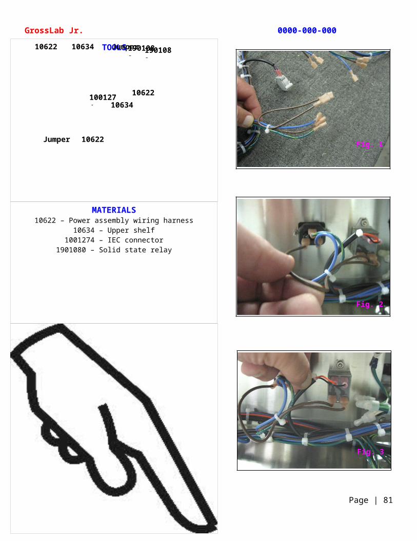
MATERIALS10622 – Power assembly wiring harness
10634 – Upper shelf1001274 – IEC connector104307 – 6-32 Keps nut
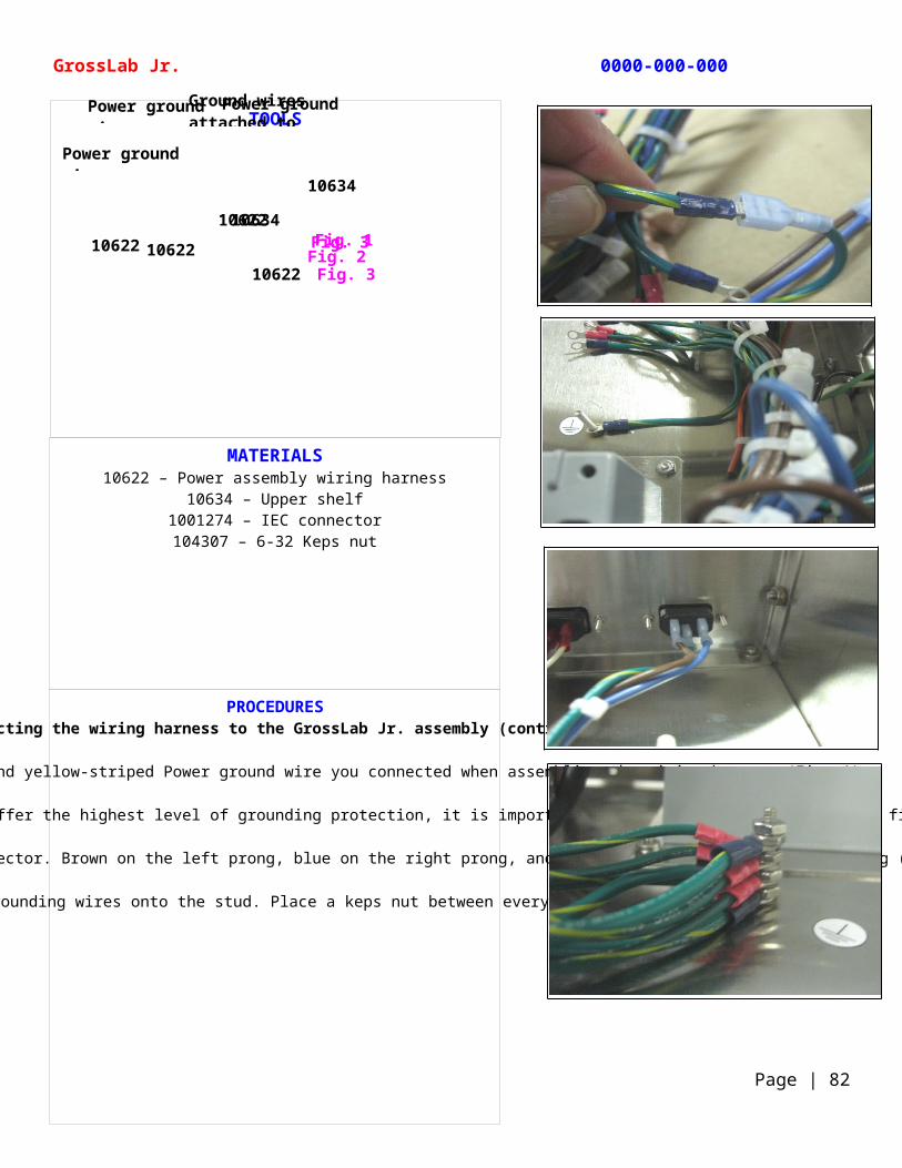
PROCEDURESConnecting the wiring harness to the GrossLab Jr. assembly (continued)
Disconnect the two ends of green and yellow-striped Power ground wire you connected when assembling the wiring harness (Fig. 1).
Attach the now disconnected end of the Power ground wire to the stud on the upper shelf. To maintain UL approval and offer the highest level of grounding protection, it is important to attach the Power ground wire first. The stacking order of the remaining ground wires is not important (Fig. 2).
Plug the 3 Power wires onto the Power IEC connector. Brown on the left prong, blue on the right prong, and the ground wire on the bottom prong (Fig. 3).
Stack the remaining grounding wires onto the stud. Place a keps nut between every second wire (Fig. 4).
TOOLS
GrossLab Jr. 0000-000-000
Page | 82
Fig. 3
Fig. 3Fig. 1Fig. 2
10622
Power ground wire
Power ground wire
10622 10622
10634
Power ground wireGround wires attached to grounding stud
10622
10634
MATERIALS10622 – Power assembly wiring harness
10633 – Florescent light fixture1000300 – Advance R-2S40TPM ballast
10634 – Upper shelf235046 – Closed-end connectors
187086 – Cable ties
PROCEDURESConnecting the wiring harness to the GrossLab Jr. assembly (continued)
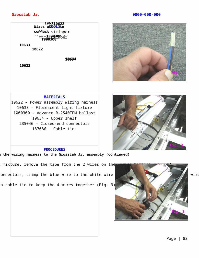
To wire the florescent light fixture, remove the tape from the 2 wires on the wiring harness (Fig. 1).
Strip the ends of the 4 wires. Using closed-end connectors, crimp the blue wire to the white wire and the brown wire to the black wire (Fig. 2).
Add a cable tie to keep the 4 wires together (Fig. 3).
TOOLSWire stripperWire crimper
GrossLab Jr. 0000-000-000
Page | 83
Wires used to connect florescent light fixture
10622
10633
1000300
10622
10634
10622
1000300
10633
10634
Fig. 1
Fig. 2
Fig. 3
MATERIALS235023 – Line cord stock cable
22 AWG orange wire22 AWG blue wire
22 AWG green wireB1005196 – Switch
B8005479-05 – Façade weldment
PROCEDURESInstalling the wiring harness to the GrossLab Jr. assembly
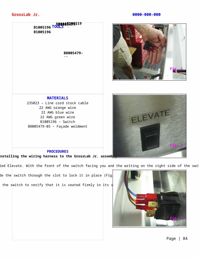
To connect the Elevate and Disposal switches, pull the wires from the separate harness through the corresponding slots in the front of the façade weldment. Pull the blue, orange, and green wires through the first slot labeled Elevate. With the front of the switch facing you and the writing on the right side of the switch, attach the 3 wires to the right side prongs. Connect the blue on top, orange wire second, and the green wire on the bottom. This switch will operate the hydraulic lift (Fig. 1).
Slide the switch through the slot to lock it in place (Fig. 2).
Look down at the switch to verify that it is seated firmly in its slot (Fig. 3).
TOOLS
GrossLab Jr. 0000-000-000
Page | 84
B8005479-05
B1005196B1005196
B8005479-05
B1005196
B8005479-05
Fig. 1
Fig. 2
Fig. 3
MATERIALS235023 – Line cord stock cable
22 AWG orange wire22 AWG blue wire
22 AWG green wireB1005197 – Switch
B8005479-05 – Façade weldment10634 – Upper shelf
PROCEDURESInstalling the wiring harness to the GrossLab Jr. assembly
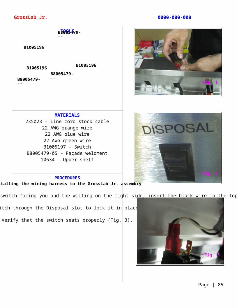
Attach the black wire on the Disposal switch the same way. With the front of the switch facing you and the writing on the right side, insert the black wire in the top slot and white wire at the bottom (Fig. 1).
Push the switch through the Disposal slot to lock it in place (Fig. 2).
Verify that the switch seats properly (Fig. 3).
TOOLS
GrossLab Jr. 0000-000-000
Page | 85
B1005196B8005479-05
B1005196
B1005196
B8005479-05
B8005479-05
Fig. 1
Fig. 2
Fig. 3
MATERIALS10622 – Power assembly wiring harness
B1005197 – SwitchB8005479-05 – Façade weldment
10634 – Upper shelf
PROCEDURESInstalling the wiring harness to the GrossLab Jr. assembly
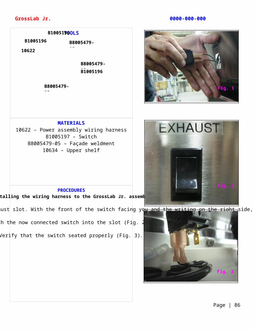
Pull the 2 black wires, which are located near the end of the wiring harness, through the Exhaust slot. With the front of the switch facing you and the writing on the right side, attach the wires to the 2 prongs on your right (Fig. 1).
Push the now connected switch into the slot (Fig. 2).
Verify that the switch seated properly (Fig. 3).
TOOLS
GrossLab Jr. 0000-000-000
Page | 86
B8005479-05
B8005479-05
B8005479-05
B1005196
B1005196
B1005196
10622
Fig. 1
Fig. 2
Fig. 3
MATERIALS10622 – Power assembly wiring harness
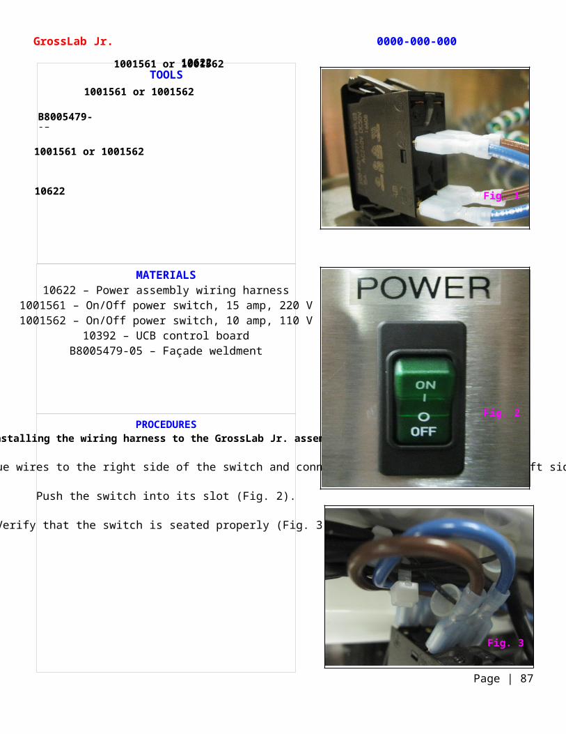
1001561 – On/Off power switch, 15 amp, 220 V1001562 – On/Off power switch, 10 amp, 110 V
10392 – UCB control boardB8005479-05 – Façade weldment
PROCEDURESInstalling the wiring harness to the GrossLab Jr. assembly
With the ON button facing up, connect the 2 blue wires to the right side of the switch and connect the 2 brown wires to the left side (Fig. 1).
Push the switch into its slot (Fig. 2).
Verify that the switch is seated properly (Fig. 3).
TOOLS
GrossLab Jr. 0000-000-000
Page | 87
B8005479-05
10622
106221001561 or 1001562
1001561 or 1001562
1001561 or 1001562
Fig. 1
Fig. 2
Fig. 3
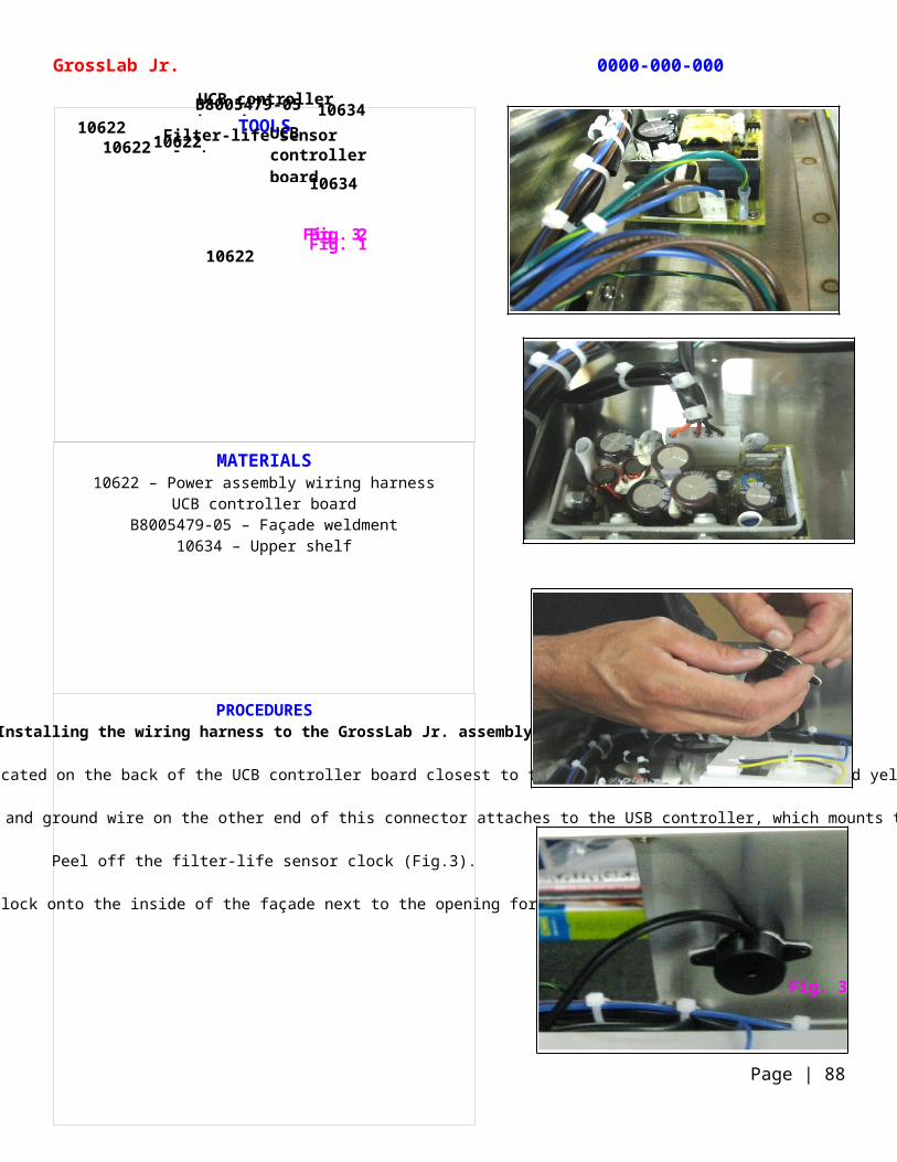
MATERIALS10622 – Power assembly wiring harness
UCB controller boardB8005479-05 – Façade weldment
10634 – Upper shelf
PROCEDURESInstalling the wiring harness to the GrossLab Jr. assembly
Push the small white connector, which contains a blue and brown wire, into its corresponding white male plug, located on the back of the UCB controller board closest to the receptacle. Attach the green and yellow-striped ground wire onto the prong next to this connection (Fig. 1).
Attach the white plug connector to the USB control board. The red, black, and ground wire on the other end of this connector attaches to the USB controller, which mounts to the front of the unit (Fig. 2).
Peel off the filter-life sensor clock (Fig.3).
Stick the filter-life sensor clock onto the inside of the façade next to the opening for the USB controller (Fig. 4).
TOOLS
GrossLab Jr. 0000-000-000
Page | 88
Fig. 3Fig. 1Fig. 2
UCB controller board
10622
10634
10634
10622 UCB controller board
1062210622
B8005479-05
Filter-life sensor clock
Fig. 3
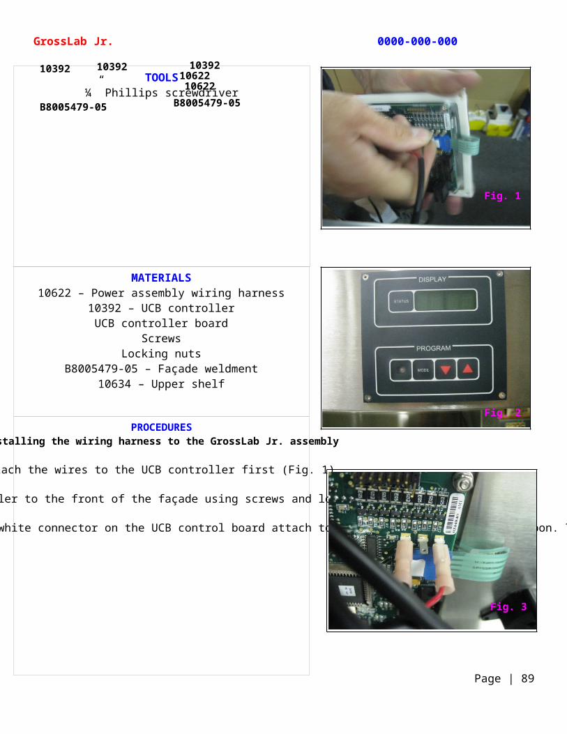
MATERIALS10622 – Power assembly wiring harness
10392 – UCB controllerUCB controller board
ScrewsLocking nuts
B8005479-05 – Façade weldment10634 – Upper shelf
PROCEDURESInstalling the wiring harness to the GrossLab Jr. assembly
Attach the wires to the UCB controller first (Fig. 1).
Mount the UCB controller to the front of the façade using screws and locking nuts (Fig. 2).
Looking inside at the now mounted UCB controller, you will notice that the red and black wires leading from the white connector on the UCB control board attach to the prongs just above the ribbon. The red on the far right prong and the black on the third prong in (Fig. 3).
TOOLS¼” Phillips screwdriver
GrossLab Jr. 0000-000-000
Page | 89
103921062210392 10392
10622
B8005479-05 B8005479-05
Fig. 1
Fig. 2
Fig. 3
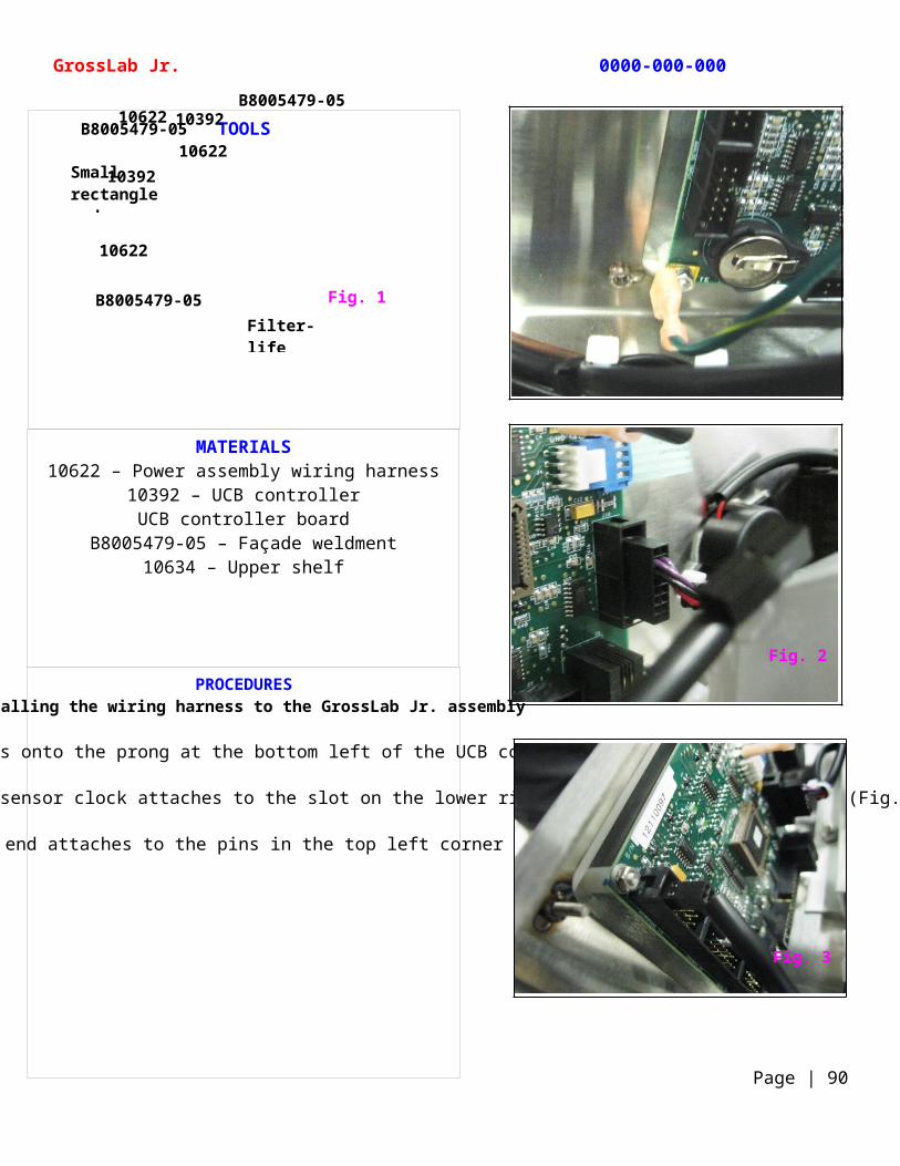
MATERIALS10622 – Power assembly wiring harness
10392 – UCB controllerUCB controller board
B8005479-05 – Façade weldment10634 – Upper shelf
PROCEDURESInstalling the wiring harness to the GrossLab Jr. assembly
The ground wire slides onto the prong at the bottom left of the UCB controller (Fig. 1).
The connector leading from the filter-life sensor clock attaches to the slot on the lower right side of the UCB controller (Fig. 2).
The wire with the small rectangle end attaches to the pins in the top left corner of the UCB controller (Fig. 3).
TOOLS
GrossLab Jr. 0000-000-000
Page | 90
10622
Small rectangle end
B8005479-05
B8005479-05
B8005479-05
10392
Fig. 1
10392
10622
10622
Filter-life sensor lock
Fig. 2
Fig. 3
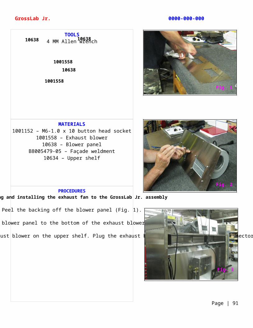
MATERIALS1001152 – M6-1.0 x 10 button head socket
1001558 – Exhaust blower10638 – Blower panel
B8005479-05 – Façade weldment10634 – Upper shelf
PROCEDURESAssembling and installing the exhaust fan to the GrossLab Jr. assembly
Peel the backing off the blower panel (Fig. 1).
Attach the blower panel to the bottom of the exhaust blower (Fig. 2).
At this point you will want to test all electronic components to verify the complete system is operational. Set the exhaust blower on the upper shelf. Plug the exhaust blower into the exhaust IEC connector on the back of the Grosslab Jr. assembly and apply power to the assembly (Fig. 3).
TOOLS4 MM Allen wrench
GrossLab Jr. 0000-000-000
Page | 91
10638
10638
1001558
1001558
10638
Fig. 1
Fig. 2
Fig. 3
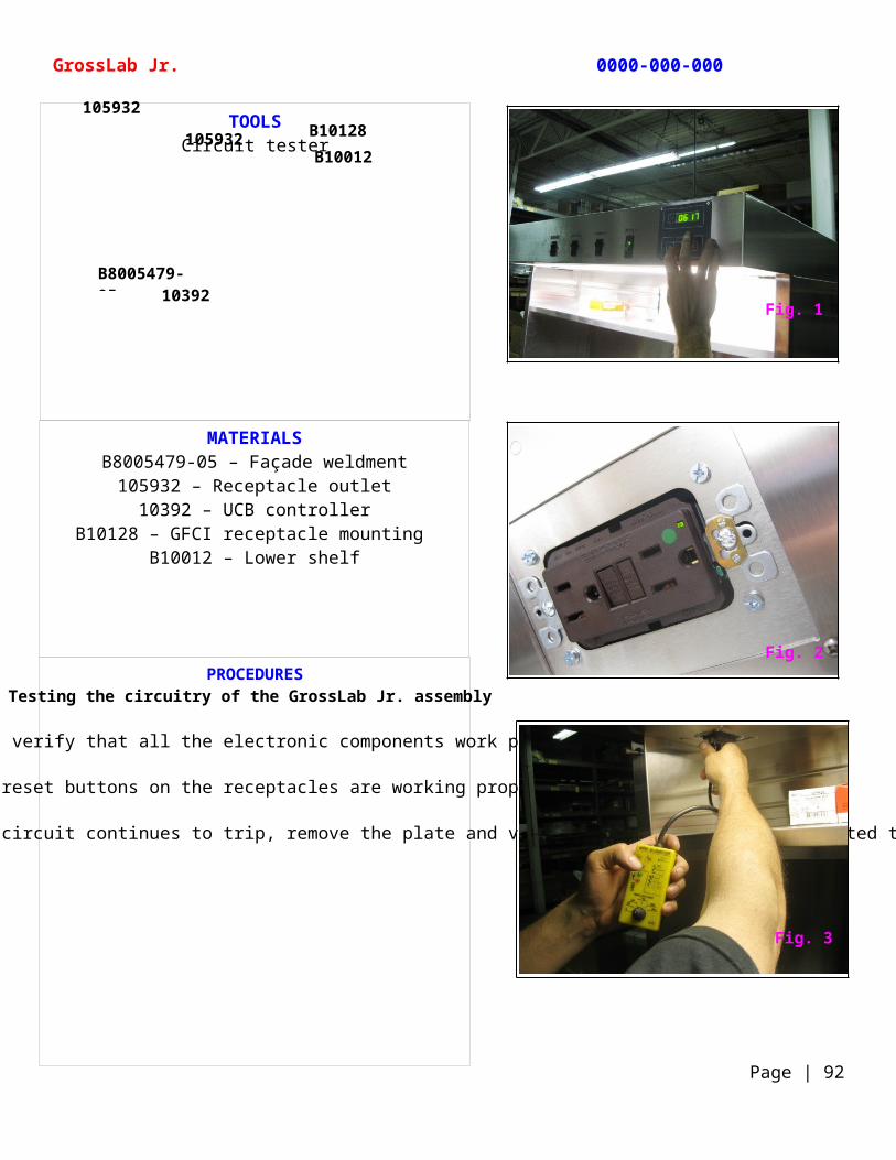
MATERIALSB8005479-05 – Façade weldment
105932 – Receptacle outlet10392 – UCB controller
B10128 – GFCI receptacle mounting B10012 – Lower shelf
PROCEDURESTesting the circuitry of the GrossLab Jr. assembly
With the power on, verify that all the electronic components work properly (Fig. 1).
Check that the reset buttons on the receptacles are working properly (Fig. 2).
Using a circuit tester, verify that both receptacles have power. If the circuit continues to trip, remove the plate and verify that all wires are connected to the receptacle properly (Fig. 3).
TOOLSCircuit tester
GrossLab Jr. 0000-000-000
Page | 92
B8005479-0510392
105932B10128B10012
105932
Fig. 1
Fig. 2
Fig. 3
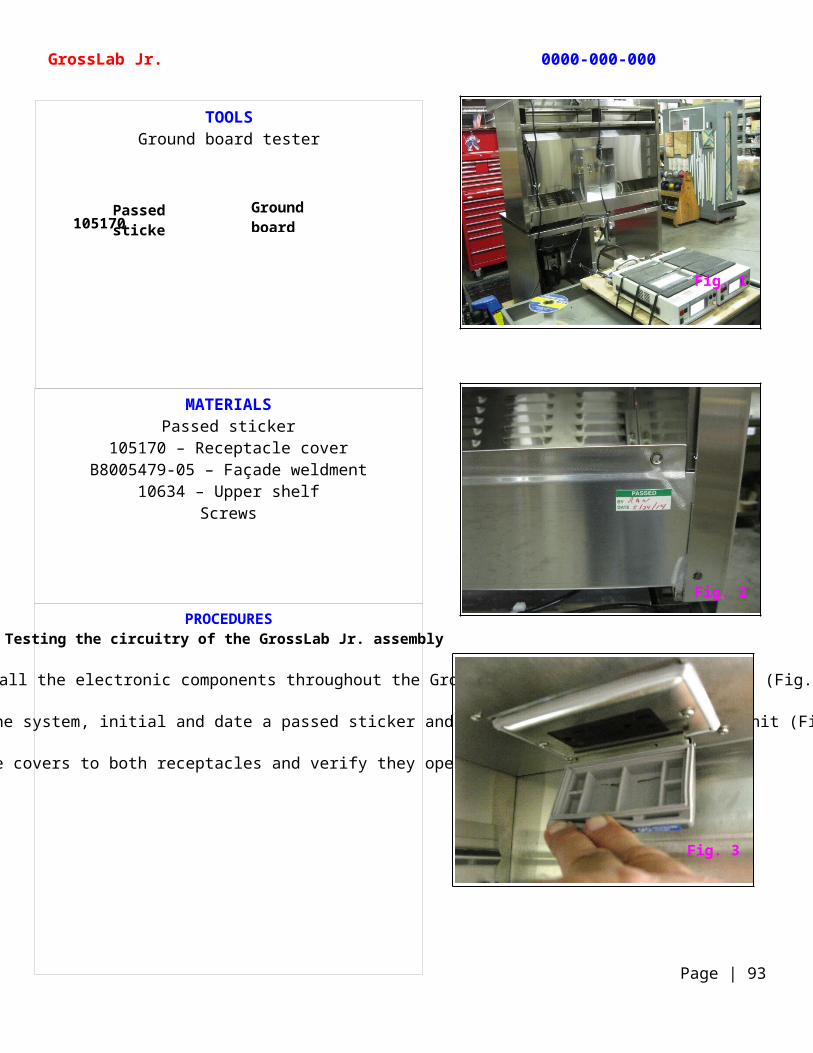
MATERIALSPassed sticker
105170 – Receptacle coverB8005479-05 – Façade weldment
10634 – Upper shelf Screws
PROCEDURESTesting the circuitry of the GrossLab Jr. assembly
Using a ground board tester, verify that all the electronic components throughout the GrossLab Jr. are properly grounded (Fig. 1).
Once you verify the complete operation of the system, initial and date a passed sticker and attach it to the back of the unit (Fig. 2).
Using screws attach receptacle covers to both receptacles and verify they open and close smoothly (Fig. 3).
TOOLSGround board tester
GrossLab Jr. 0000-000-000
Page | 93
Ground board tester
Passed sticker105170
Fig. 1
Fig. 2
Fig. 3
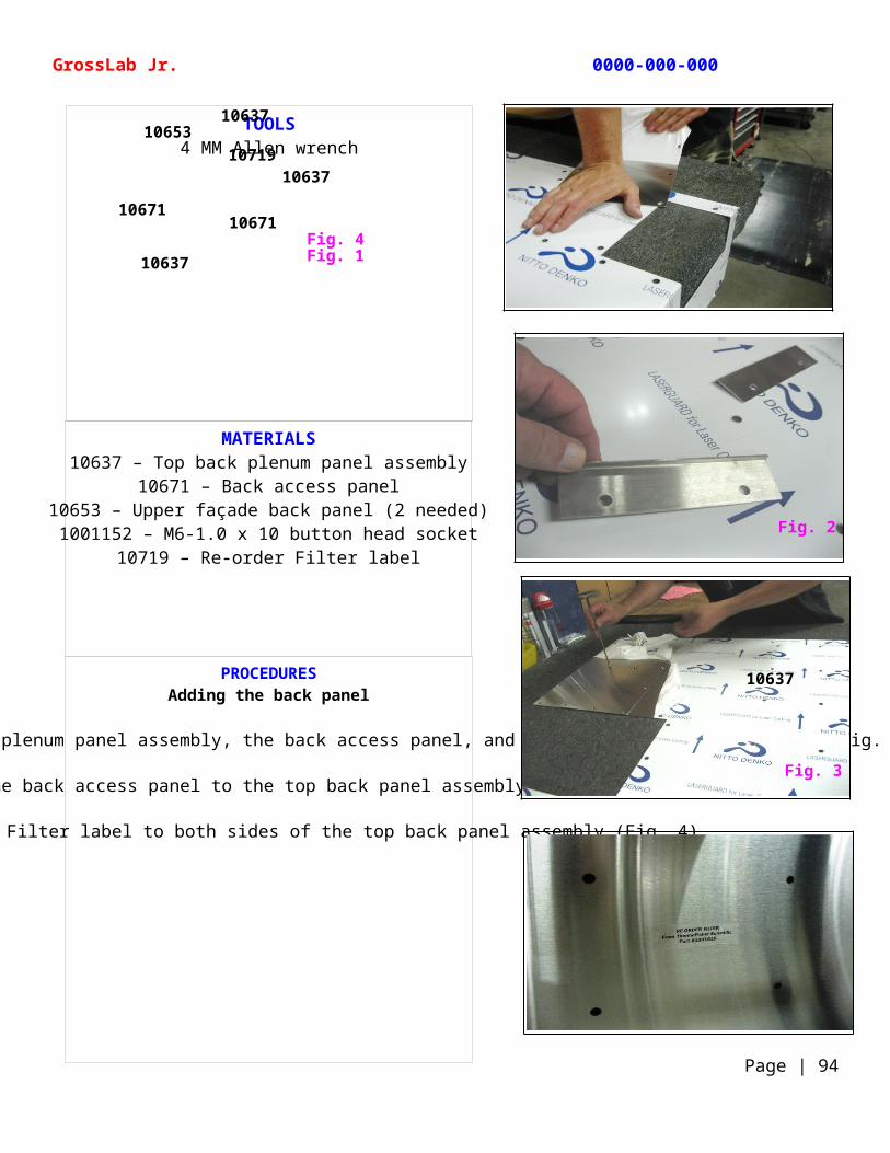
MATERIALS10637 – Top back plenum panel assembly
10671 – Back access panel10653 – Upper façade back panel (2 needed)1001152 – M6-1.0 x 10 button head socket
10719 – Re-order Filter label
PROCEDURESAdding the back panel
Remove the protective backing from the top back plenum panel assembly, the back access panel, and the upper façade back panels (Fig. 1 and Fig. 2).
Attach the back access panel to the top back panel assembly (Fig. 3).
Apply 2 Re-order Filter label to both sides of the top back panel assembly (Fig. 4).
TOOLS4 MM Allen wrench
GrossLab Jr. 0000-000-000
Page | 94
Fig. 4Fig. 110637
10671
10637
10653
10671
10637
10719
Fig. 2
Fig. 3
10637
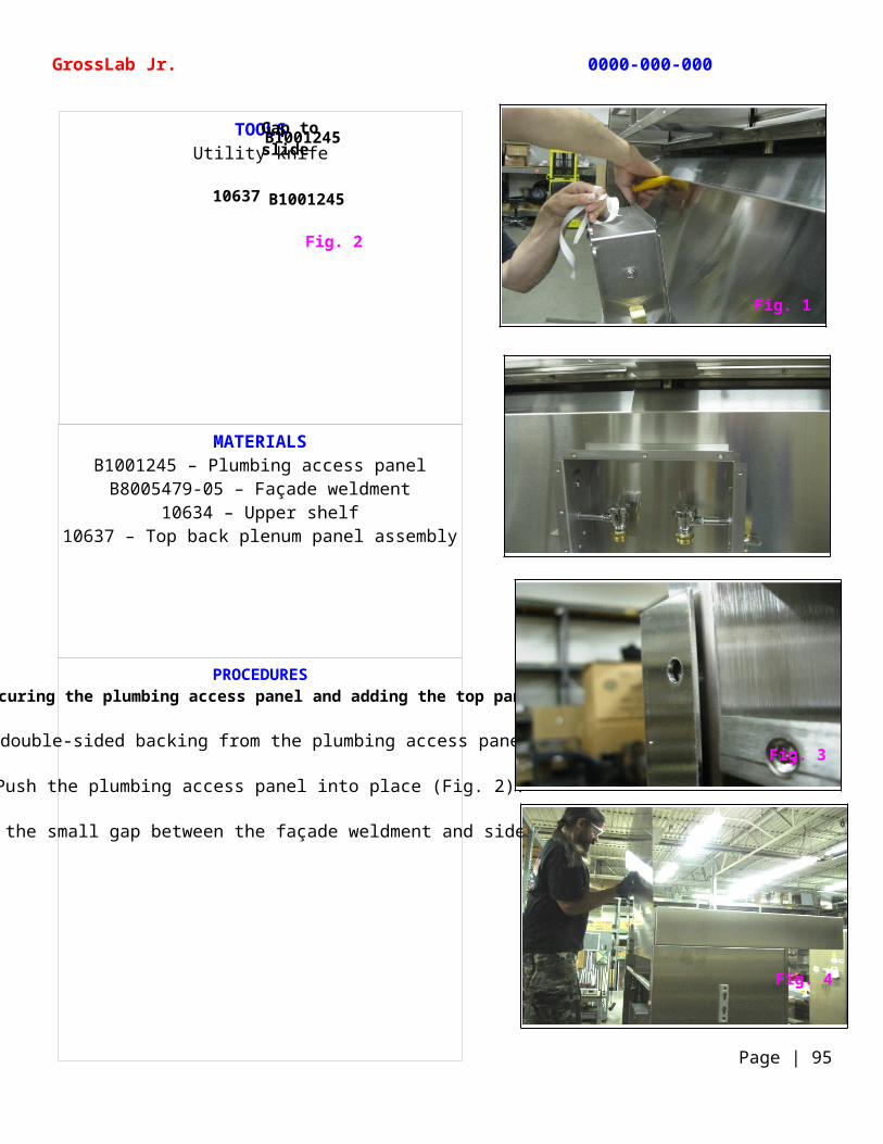
MATERIALSB1001245 – Plumbing access panelB8005479-05 – Façade weldment
10634 – Upper shelf10637 – Top back plenum panel assembly
PROCEDURESSecuring the plumbing access panel and adding the top panel
Remove the double-sided backing from the plumbing access panel (Fig. 1).
Push the plumbing access panel into place (Fig. 2).
Slide the back panel through the small gap between the façade weldment and side panels (Fig. 3 and Fig. 4).
TOOLSUtility knife
GrossLab Jr. 0000-000-000
Page | 95
Fig. 2
B1001245
B1001245Gap to slide 10637
10637
Fig. 1
Fig. 3
Fig. 4
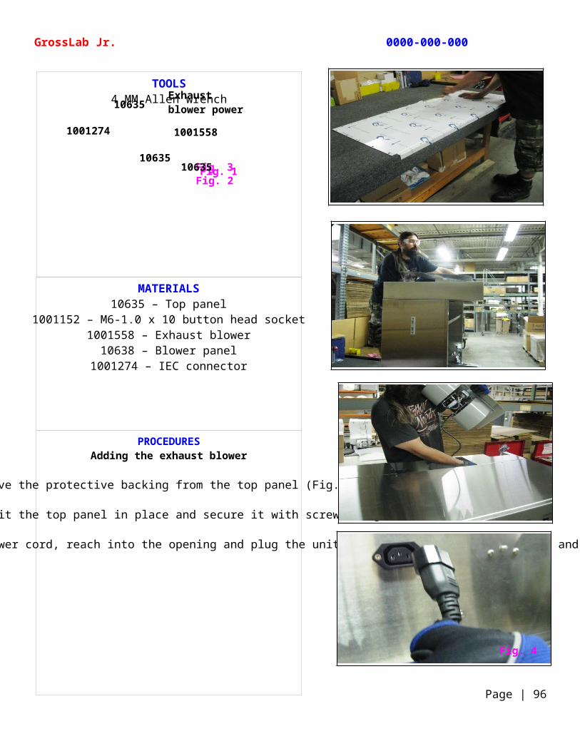
MATERIALS10635 – Top panel
1001152 – M6-1.0 x 10 button head socket1001558 – Exhaust blower
10638 – Blower panel1001274 – IEC connector
PROCEDURESAdding the exhaust blower
Remove the protective backing from the top panel (Fig. 1).
Carefully fit the top panel in place and secure it with screws (Fig. 2).
Grasping the end of the exhaust blower’s power cord, reach into the opening and plug the unit into its IEC connector (Fig. 3 and Fig.4).
TOOLS4 MM Allen wrench
GrossLab Jr. 0000-000-000
Page | 96
Fig. 3Fig. 1Fig. 2
10635
1063510635
Exhaust blower power cord
1001274 1001558
Fig. 4
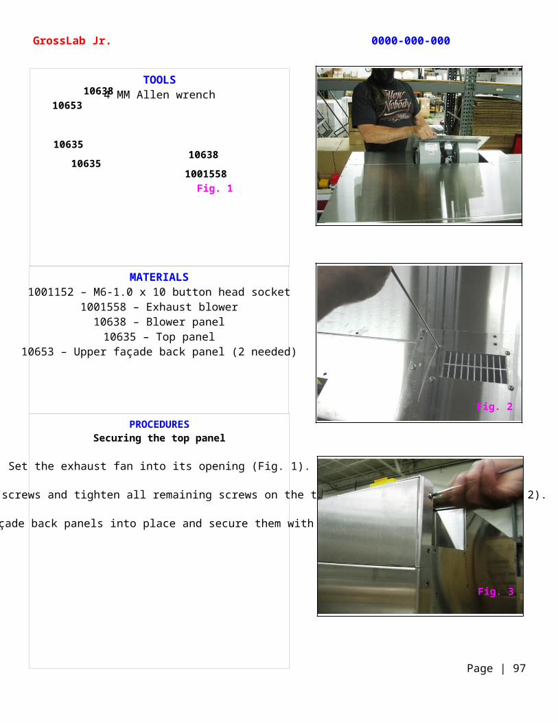
MATERIALS1001152 – M6-1.0 x 10 button head socket
1001558 – Exhaust blower10638 – Blower panel
10635 – Top panel10653 – Upper façade back panel (2 needed)
PROCEDURESSecuring the top panel
Set the exhaust fan into its opening (Fig. 1).
Use an Allen wrench to tighten the screws and tighten all remaining screws on the top, side, and back panels (Fig. 2).
Fit the upper façade back panels into place and secure them with screws (Fig. 3).
TOOLS4 MM Allen wrench
GrossLab Jr. 0000-000-000
Page | 97
Fig. 1
1063510638
1001558
10638
10635
10653
Fig. 2
Fig. 3
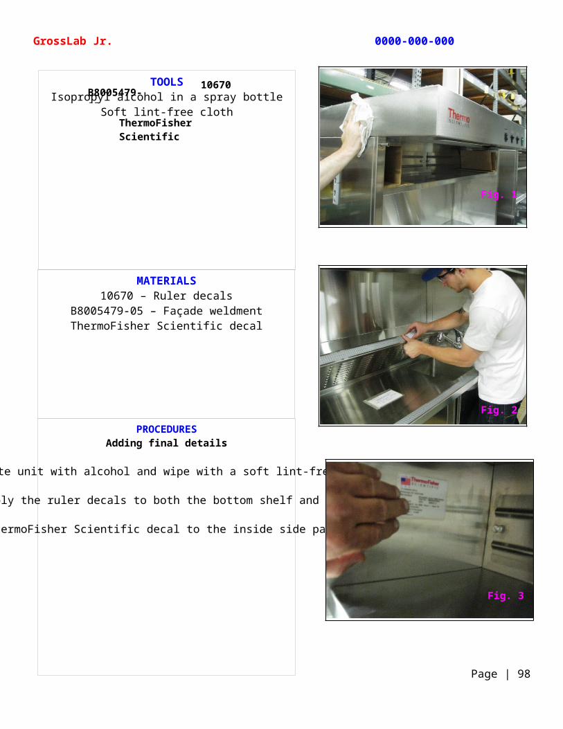
MATERIALS10670 – Ruler decals
B8005479-05 – Façade weldmentThermoFisher Scientific decal
PROCEDURESAdding final details
Spray the complete unit with alcohol and wipe with a soft lint-free cloth (Fig. 1).
Carefully apply the ruler decals to both the bottom shelf and sink (Fig. 2).
Apply the ThermoFisher Scientific decal to the inside side panel (Fig. 3).
TOOLSIsopropyl alcohol in a spray bottle
Soft lint-free cloth
GrossLab Jr. 0000-000-000
Page | 98
B8005479-0510670
ThermoFisher Scientific decal
Fig. 1
Fig. 1
Fig. 2
Fig. 3
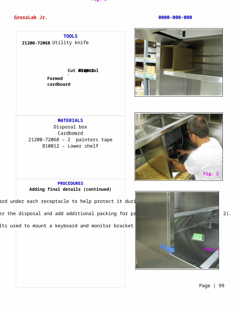
MATERIALSDisposal boxCardboard
21200-72068 – 2” painters tapeB10012 – Lower shelf
PROCEDURESAdding final details (continued)
Place formed cardboard under each receptacle to help protect it during shipping (Fig. 1).
Cut and fit the disposal box under the disposal and add additional packing for protection during shipping (Fig. 2).
Apply tape over the bolts used to mount a keyboard and monitor bracket for future use (Fig. 3).
TOOLSUtility knife
GrossLab Jr. 0000-000-000
Page | 99
Cut disposal box
Formed cardboard
B10012
Fig. 1
21200-72068
Fig. 2
Fig. 3
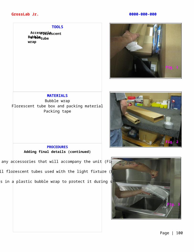
MATERIALSBubble wrap
Florescent tube box and packing materialPacking tape
PROCEDURESAdding final details (continued)
Pack any accessories that will accompany the unit (Fig. 1).
Pack all florescent tubes used with the light fixture (Fig. 2).
Wrap the fixtures in a plastic bubble wrap to protect it during shipping (Fig. 3).
TOOLS
GrossLab Jr. 0000-000-000
Page | 100
Accessories box
Florescent tube packagingBubble
wrap
Fig. 1
Fig. 2
Fig. 3