
Greenpac Soil Excavation IRM Work Plan June 2011 · SOIL EXCAVATION IRM WORK PLAN Former Mill No. 2...
297
Greenpac Mill, LLC Soil Excavation IRM Work Plan Former Mill No. 2 Site - Niagara Falls, New York NYSDEC BCP Site Number C932150 June 2011 Environmental Resources Management 5788 Widewaters Parkway DeWitt, New York 13214 www.erm.com
-
Upload
dinhkhuong -
Category
Documents
-
view
214 -
download
0
Transcript of Greenpac Soil Excavation IRM Work Plan June 2011 · SOIL EXCAVATION IRM WORK PLAN Former Mill No. 2...

Greenpac Mill, LLC
Soil Excavation IRM Work Plan Former Mill No. 2 Site - Niagara Falls, New York NYSDEC BCP Site Number C932150 June 2011 Environmental Resources Management 5788 Widewaters Parkway DeWitt, New York 13214 www.erm.com

SOIL EXCAVATION IRM WORK PLAN Former Mill No. 2 Site - Niagara Falls, New York NYSDEC BCP Site Number C932150 June 2011 ERM Project Number 0128459
Prepared by:
Environmental Resources Management 5788 Widewaters Parkway Dewitt, New York 13214

III
TABLE OF CONTENTS
1.0 INTRODUCTION.............................................................................................................1
1.1 PROJECT BACKGROUND.................................................................................1
1.2 PROJECT OBJECTIVES ......................................................................................3
2.0 ENGINEERING EVALUATION.....................................................................................4
3.0 SCOPE OF WORK ...........................................................................................................6
3.1 OVERVIEW............................................................................................................6
3.2 SITE SECURITY....................................................................................................6
3.3 UNDERGROUND UTILITIES ...........................................................................6
3.4 SOIL EROSION AND SEDIMENT CONTROL...............................................7
3.5 STORM WATER MANAGEMENT ....................................................................7
3.6 HEALTH & SAFETY AND AIR MONITORING .............................................7
3.7 PRE-IRM DELINEATION SAMPLING...........................................................8
3.8 STRUCTURAL EXCAVATION EVALUATION AND CONTROLS.............9
3.9 MOBILIZATION ..................................................................................................9
3.10 EXCAVATION OF IRM SOILS.......................................................................10 3.10.1 Historic Fill................................................................................................10 3.10.2 Native Soil .................................................................................................11
3.11 OFF-SITE SOIL TRANSPORTATION............................................................11 3.11.1 Preparation of Soil Transport Vehicles................................................11 3.11.2 Off-Site Transportation of Hazardous Soil..........................................11
3.12 CONFIRMATION SOIL SAMPLING .............................................................12
3.13 SITE RESTORATION ........................................................................................13
4.0 QUALITY ASSURANCE/QUALITY CONTROL.......................................................14

IV
5.0 IRM CONSTRUCTION COMPLETION REPORT...................................................15
6.0 PROJECT SCHEDULE...................................................................................................16
LIST OF FIGURES 1 Site Location Map 2 Site Layout Map and Area of Excavation 3 Estimated Project Schedule
LIST OF TABLES 1 Soil Management by Categories LIST OF APPENDICES A Health & Safety Plan

ERM 1 Greenpac SOIL EXCAVATION IRM WORK PLAN_16 JUNE.DOC
1.0 INTRODUCTION
1.1 PROJECT BACKGROUND
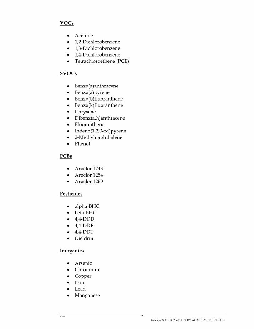
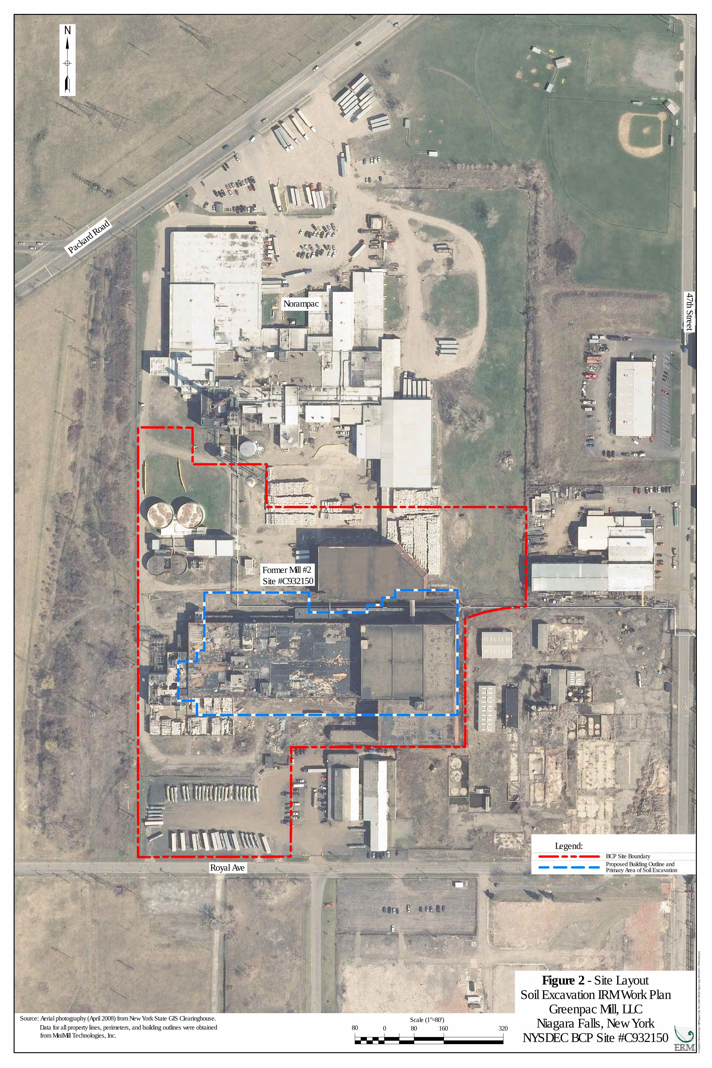
This Soil Excavation Interim Remedial Measure (IRM) Work Plan identifies the activities and tasks associated with the excavation of affected soil within the parcel identified as Brownfield Cleanup Program (BCP) Site Number C932150 located at 4001 Packard Road in the City of Niagara Falls, Niagara County, New York (the Site). Greenpac Mill, LLC (Greenpac) has entered into a Brownfield Cleanup Agreement with the New York State Department of Environmental Conservation (NYSDEC) to facilitate the voluntary redevelopment and reuse of the Site. Project activities will be conducted consistent with the BCP and applicable NYSDEC guidance. Figure 1 shows the location of the Site. Figure 2 shows the layout of the property and selected Site features. The Site is located in an industrial urban area in Niagara Falls, New York. Buildings, facilities, and operations at the Site are associated with the Former Mill No. 2 which historically housed paper manufacturing, finishing, and packaging operations of finished goods. The facility was originally constructed in the 1920s and was expanded several times. Given the age of the structures, common construction and building materials and architectural coatings are likely to contain asbestos, lead, and/or polychlorinated biphenyls (PCBs). Former Mill No. 2 structures are in the process of being demolished to allow construction of a new, state-of-the-art fiberboard recycling facility. Excavation of soil will be required to install foundations for the new facility. Additionally, Remedial Investigation (RI) is ongoing at the Site. Data and information obtained from RI activities completed to date have been reviewed and incorporated as appropriate into this IRM Work Plan. RI site work performed to date has identified isolated areas of affected soil away from the proposed new building at the Site that will also be removed by excavation to the extent practicable. This IRM Work Plan has been developed based upon information that was available at the time of issuance and may be amended if other conditions become evident. To date, the following compounds have been detected in one or more soil samples at the Site at concentrations exceeding one or more 6 NYCRR Part 375 soil cleanup objectives (SCOs). The NYSDEC has determined that SCOs for the Protection of Ecological Resources do not apply to this Site.
ERM 2 Greenpac SOIL EXCAVATION IRM WORK PLAN_16 JUNE.DOC
VOCs
Acetone 1,2-Dichlorobenzene 1,3-Dichlorobenzene 1,4-Dichlorobenzene Tetrachloroethene (PCE)
SVOCs
Benzo(a)anthracene Benzo(a)pyrene Benzo(b)fluoranthene Benzo(k)fluoranthene Chrysene Dibenz(a,h)anthracene Fluoranthene Indeno(1,2,3-cd)pyrene 2-Methylnaphthalene Phenol
PCBs
Aroclor 1248 Aroclor 1254 Aroclor 1260
Pesticides
alpha-BHC beta-BHC 4,4-DDD 4,4-DDE 4,4-DDT Dieldrin
Inorganics
Arsenic Chromium Copper Iron Lead Manganese

ERM 3 Greenpac SOIL EXCAVATION IRM WORK PLAN_16 JUNE.DOC
Mercury Nickel Selenium Zinc
1.2 PROJECT OBJECTIVES Available data indicate that implementation of a Soil Excavation IRM at the Site is appropriate to address anticipated source areas of contaminated soil that will likely be encountered during the construction and installation of foundations for the new recycling facility building and isolated areas of contamination at the Site. Excavation and removal of contaminated soil will facilitate protection of human health and the environment through recovery of contaminant mass and elimination or control of potential exposure. Soil excavation IRM activities will incorporate New York State requirements for soil erosion and sedimentation control. Excavated soil will be screened in the field and segregated for reuse on-site, reuse off-site, or disposal off-site at a permitted soil disposal or recycling facility pending the results of sampling and laboratory analyses in conformance with NYSDEC technical requirements for soil reuse and remedial action implementation compliance as contained in NYSDEC’s Technical Guidance for Site Investigation and Remediation (DER-10). The effectiveness of the IRM will be assessed through collection of confirmation soil samples in conformance with DER-10 technical requirements and comparison of the post-remediation sampling results with pre-remediation sampling results. Work performed, results, and conclusions from the IRM effort will be summarized and presented in an IRM Construction Completion Report that will be submitted to the NYSDEC for review.

ERM 4 Greenpac SOIL EXCAVATION IRM WORK PLAN_16 JUNE.DOC
2.0 ENGINEERING EVALUATION This IRM involves excavation of affected soil containing compounds of potential concern at concentrations above applicable SCOs as defined in 6 NYCRR Part 375-6.8. The SCOs are intended to be applied to the top 15 feet of soil (or to bedrock if less than 15 feet) consistent with NYSDEC’s “Soil Cleanup Guidance” Policy dated 21 October 2011 (CP-51). The current and contemplated use for the Site is industrial. The current, intended, or reasonably anticipated use of an area within the Site may be considered in the determination of applicable SCOs on an area-specific basis. Protection of Human Health and the Environment The remedy will remove affected soil that could represent a potential source of dermal contact exposure, vapor intrusion to on-Site buildings, and/or leaching to ground water. During the excavation, air monitoring for dust and volatile organic compounds (VOCs) will be performed. Therefore, the IRM is protective of human health and the environment. Standards, Criteria, & Guidance (SCG) As discussed above, the remedy will remove soil in excess of applicable SCOs as determined through consideration of the current, intended, or reasonably anticipated use of the Site. Short-term Effectiveness & Impacts During the excavation, air monitoring will be conducted as documented in the Health & Safety Plan (Appendix A) to prevent Site workers and the surrounding area from exposure to dust and VOCs. The excavation will be conducted over a period of several months. During this period, it is anticipated that there will be a slight increase in truck traffic associated with transportation of excavated soil from the Site. It is anticipated that the production rate will be between 20 and 40 trucks per day. Therefore, the short-term impacts associated with this project are acceptable. Long-term Effectiveness & Permanence Excavation will permanently remove affected soil from the Site. Reduction of Toxicity, Mobility, or Volume Soil containing compounds of potential concern above applicable SCOs will be permanently removed from the Site.

ERM 5 Greenpac SOIL EXCAVATION IRM WORK PLAN_16 JUNE.DOC
Implementability No approvals are required from other agencies, and the equipment is readily available to perform the excavation. Therefore, the IRM is readily implementable.

ERM 6 Greenpac SOIL EXCAVATION IRM WORK PLAN_16 JUNE.DOC
3.0 SCOPE OF WORK 3.1 OVERVIEW
Figure 2 shows the extent of the proposed new building for the paperboard recycling facility. It is currently anticipated that most of this area will be excavated to the top of bedrock at an approximate depth of 12-feet below ground surface. This corresponds to approximately 85,000 cubic yards (approximately 127,500 tons). The Majority of the soil in the excavation area is expected to be suitable for re-use in off-site areas pending soil analysis in accordance with part 375 and DER-10 to identify re-use options. It is anticipated that some soil encountered during the foundation excavations will require transportation and disposal off-site at a NYSDEC-approved soil disposal, recycling, or reuse facility. Additional areas of affected soil away from the proposed new building will also be excavated after the RI is completed and the extent of the affected soil in these areas has been more fully evaluated. The volume of soil that will be excavated in areas away from the proposed new building is currently unknown. Details regarding the approach and specific tasks associated with implementation of the Soil Excavation IRM are described below.
3.2 SITE SECURITY
The entry point from Royal Avenue to the project area is guarded by security personnel. The excavation contractor will also erect a suitable fence to prohibit entry into work areas by unauthorized personnel. Also, Norampac has a closed circuit video surveillance system that is capable of viewing the area adjacent to the Former Mill No. 2. The surveillance system is monitored on a regular basis.
3.3 UNDERGROUND UTILITIES
Prior to initiating excavation work, all underground utilities potentially affected by the project will be identified by the excavation contractor. The excavation contractor will file a request with Dig Safely New York to facilitate the identification, location, and marking of subsurface utilities. In addition, private utility clearance using ground penetrating radar (GPR) and/or other appropriate technologies should also be conducted.

ERM 7 Greenpac SOIL EXCAVATION IRM WORK PLAN_16 JUNE.DOC
As appropriate, certain utilities will need to be protected and remain active while others will be shutdown/de-energized, terminated, and/or removed to facilitate excavation activities.
3.4 SOIL EROSION AND SEDIMENT CONTROL
The New York State Standards and Specifications for Soil Erosion and Sediment Controls require an Erosion & Sediment Control Plan (ESCP) for any construction activity that disturbs one or more acres. The excavation contractor shall prepare a ESCP and implement the plan in a manner consistent with the New York State Standards and Specifications for Soil Erosion and Sediment Control. Soil erosion and sedimentation controls will be installed at the Site to minimize the potential for erosion and migration of excavated soil and to control precipitation and storm water runoff in IRM work areas. Anticipated controls may include silt fence and hay bales around excavation, grading, and soil staging areas. A silt fence will be installed along the perimeter of excavation work areas. The silt fence will be anchored a minimum of 6-inches into the ground and staked every 10-feet. Hay bales or equivalent will be used in conjunction with the silt fence in any low-lying areas or areas that may be expected to receive a greater amount of run-off. Inspection and proper maintenance of the controls will be performed by the excavation contractor during IRM activities.
3.5 STORM WATER MANAGEMENT
The area of disturbance of soil excavation activities will exceed 5-acres. Therefore, the excavation contractor shall indentify plan components and prepare a full Storm Water Pollution Prevention Plan (SWPPP) for the project. A Notice of Intent for storm water discharges from construction activities in New York will be filed with the NYSDEC. The SWPPP will be implemented by the excavation contractor in a manner consistent with the New York State Standards and Specifications for Soil Erosion and Sediment Control.
3.6 HEALTH & SAFETY AND AIR MONITORING A Site-specific Health and Safety Plan (HASP) is presented in Appendix A. The procedures set forth in the HASP are designed to minimize the risk of exposure to chemical substances and physical hazards that may be

ERM 8 Greenpac SOIL EXCAVATION IRM WORK PLAN_16 JUNE.DOC
present at the Site. These procedures generally conform to applicable federal, state and local regulations, including Occupational Safety and Health Administration (OSHA) requirements governing activities at hazardous waste sites and the requirements in 29 CFR 1910.120 (Hazardous Waste Operations) and 29 CFR 1926.650 (Excavations and Trenching). Specific practices and procedures, including the level of personal protective equipment (PPE), are based on a review of currently available information for the Site. Every potential safety hazard associated with this IRM may not be predicted. This HASP does not attempt to establish rules to cover every contingency that may arise, but it does provide a basic framework for the safe completion of field activities and plans for reasonable contingencies. ERM will conduct on-Site air monitoring consistent with the requirements of a generic Community Air Monitoring Program (CAMP) as contained in Appendix 1A of DER-10. A Site-specific CAMP is provided in Appendix K of the HASP. In accordance with the CAMP, air monitoring stations equipped with a photoionization detector (PID) for field measurement of VOCs, and an aerosol dust monitor will be established at the downwind perimeter of the work area to monitor for potential particulate emissions (dust) from excavation activities. An upwind dust monitor will also be provided. Readings will be collected approximately every 15 minutes and recorded. In addition, a PID and dust monitor will be used within the work zone to monitor for potential worker exposure and satisfy the requirements of the HASP. A qualified professional will implement the CAMP. Fugitive dust suppression practices will be implemented by the excavation contractor when deemed necessary by the qualified professional or Site Safety Officer to facilitate protection of Site worker safety and the public.
3.7 PRE-IRM DELINEATION SAMPLING Results from previous environmental investigations at the Site and the on-going RI will be used for the pre-remedial delineation of the extent of soil requiring excavation. The pre-remedial sampling will be used to determine disposal or re-use options for excavated soil. The pre-remedial sampling, in combination with the confirmation sampling, will meet the requirements in DER-10 Section 5.4(b)5 for evaluation of the effectiveness of the remedial action. All results will be used as appropriate to modify the extent of the excavation. Data will also be used to identify proper soil handling

ERM 9 Greenpac SOIL EXCAVATION IRM WORK PLAN_16 JUNE.DOC
requirements. If necessary, additional excavation endpoint confirmation samples will be collected as requisite under Section 5.4(b)5 of DER-10.
3.8 STRUCTURAL EXCAVATION EVALUATION AND CONTROLS
Excavation may be required adjacent to the Site buildings. Prior to proceeding with remedial excavations adjacent to buildings or other structural elements that may require protection, the excavation contractor will conduct a thorough review of any available building design drawings and any building design geotechnical data to verify the present understanding of the building foundation and other salient elements. The excavation contractor will propose an excavation approach that can be conducted safely and will facilitate the protection of the structural integrity of buildings. The over excavation requirements needed to achieve safe side slopes were considered when determining the number of samples to be collected.
3.9 MOBILIZATION
The initial mobilization activity will consist of an on-Site meeting with the construction manager, the engineer, the remedial contractor’s construction supervisor, and other relevant personnel to review the details of the project, tour the Site and discuss implementation details, safety concerns, soil staging activities, and other salient considerations. Prior to the start of any excavation or Site clearing work, a subsurface clearance review of the Site will be conducted. Support facilities including an equipment/vehicle decontamination pad and equipment staging areas will be prepared at the Site. Additionally, staging areas for the temporary storage of excavated “clean” soil, or any affected soil that will not be live-loaded for off-site transport and disposal, will be constructed adjacent to excavation areas. Soil staging areas will be constructed with a double layer of 6-mil polyethylene sheeting bermed at the sides with hay bales or equivalent material of similar mass and shape. Staged excavated soil will be covered at the end of each work day and during moderate or heavy precipitation events. These facilities will meet the requirements established in the HASP for the Exclusion Zone, Contamination Reduction Zone, and the Support Zone.

ERM 10 Greenpac SOIL EXCAVATION IRM WORK PLAN_16 JUNE.DOC
3.10 EXCAVATION OF IRM SOILS Excavation work will be performed under the supervision of a competent person and will be performed in compliance with relevant sections of the HASP (Appendix A). It is envisioned that the Soil Excavation IRM can be performed using “Level D” PPE. Community air monitoring will be performed during excavation activities as outlined in the CAMP. Excavation will proceed according to the plan and approach prepared by the excavation contractor. Excavation controls, if necessary, will be installed per the structural engineering design and excavation shall proceed. The excavation contractor will protect (or remove and replace) existing utilities, if necessary, during excavation activities. The excavation contractor will evaluate soil type and slope of excavation walls appropriately in conformance with OSHA Publication 2226 and any applicable federal, state, or local laws, rules, codes, standards, or regulations. Entry of personnel into any excavation area greater than 4-feet in depth will not be permitted unless all applicable provisions of any relevant excavation safety regulations are satisfied. De-watering of excavation areas will be performed if necessary based on Site conditions. Construction de-watering effluent will be managed by the excavation contractor in a manner consistent with applicable regulations. Soil excavation activities have the potential to generate fugitive dust. Standard preventative measures will be employed where applicable including covering of soil piles during precipitation events and at the end of each work day. The primary dust control technique will be application of a fine water spray. Staging areas for the temporary storage of excavated “clean” soil, or any affected soil that will not be live-loaded for off-site transport and disposal, will be constructed adjacent to excavation areas. Temporary excavation staging areas will be constructed with double layer of 6-mil polyethylene sheeting bermed at the sides with hay bales or equivalent material of similar mass and shape. Staged excavated soil will be covered at the end of each work day and during moderate or heavy precipitation events.
3.10.1 Historic Fill Historic fill located less than 1-foot below ground surface will be live loaded for off-site transport and taken to a disposal or recycling facility. Historic fill may also be qualified for reuse on or off-site if it meets the criteria in described in Table 1 for Soil “Deemed” Solid Waste.

ERM 11 Greenpac SOIL EXCAVATION IRM WORK PLAN_16 JUNE.DOC
3.10.2 Native Soil Excavated soil will be examined in the field for visual, olfactory, or PID field screening evidence of potential contamination. The on-site competent person will evaluate soil intended for off-site reuse for consistency with soil conditions observed during the pre-IRM sampling program. “Clean” excavated soil will be temporarily staged for characterization, if necessary, as described in Table 1. It is currently anticipated that affected soil may be live-loaded into vehicles for transport and disposal (or reuse) off site as described in Table 1 presuming approval is previously received from the facility accepting the waste.
3.11 OFF-SITE SOIL TRANSPORTATION
Management practices for clean soil and wastes generated during implementation of the Soil Excavation IRM will be focused on the primary goal of minimizing the volume of waste that requires off-site management and disposal. ERM anticipates that most waste generated during implementation of the IRM will be determined to be non-hazardous waste. Management of all clean soil and wastes generated during the IRM will be performed in conformance with applicable federal, state, and local laws and regulations.
3.11.1 Preparation of Soil Transport Vehicles All off-Site transport vehicles (or roll-off boxes) will be equipped with a weatherproof tarp that will be secured over each shipment leaving the Site or upon placement of waste within the container. The only exception will be made for enclosed transport units. Following tarping, each transport vehicle will be visually inspected and decontaminated if required to ensure that no loose soil or other material is tracked off-Site. Particular attention will be paid to removing materials from tires, undercarriages, and portions of vehicles which may have been in contact with soil materials during loading operations.
3.11.2 Off-Site Transportation of Hazardous Soil
All trucks carrying hazardous soil or other remediation-derived waste for off-Site disposal will be labeled and manifested prior to leaving the Site for the off-Site treatment and disposal facility. Analytical results obtained during previous investigations and the RI will be used for preliminary waste determinations. Additional samples may be required and collected

ERM 12 Greenpac SOIL EXCAVATION IRM WORK PLAN_16 JUNE.DOC
in accordance with the disposal facility permit requirements for waste profiling/manifesting purposes and for determining the necessary placarding of vehicles. The manifests will be consistent with 40 CFR Part 262 “Standards Applicable to Generators of Hazardous Waste,” 40 CFR Part 263 “Standards Applicable to Transporters of Hazardous Waste,” and 6 NYCRR Part 372 “New York Hazardous Waste Manifest System Regulations” as applicable. The United States Environmental Protection Agency (USEPA) hazardous waste generator number for the facility will be used on all manifests. All hazardous waste manifests will be signed by a qualified individual with the required United States Department of Transportation (USDOT) training. All soil leaving the Site will be weighed upon arrival at the disposal/treatment facility. Only transporters which are licensed and permitted by the USEPA, USDOT, and the State of New York will be used for the transport of any hazardous soils. Documentation of the required licenses will be obtained prior to any waste being shipped. Transporters will be in compliance with applicable state and federal hazardous waste transportation requirements (i.e., 40 CFR Part 263 and 6 NYCRR Part 364). If hazardous soils are disposed outside of New York State, transporters will be required to be licensed in the appropriate state(s) or provinces as well as comply with other applicable federal laws, including USDOT requirements.
3.12 CONFIRMATION SOIL SAMPLING
Confirmation soil sampling will be conducted in accordance with Section 5.4(b)5 of DER-10. Pre-IRM and RI soil sampling results may be used to document excavation endpoint conditions, if appropriate, which may result in reduced sampling frequency relative to DER-10. Confirmation samples will be collected from excavation walls and the floor of the excavation (if the floor is soil). Confirmation samples will not be collected if the excavation floor is in bedrock. All samples will be analyzed for parameters of concern for the specific area based on consultation with the NYSDEC. Sample analyses will be expedited to the extent practicable to minimize the duration of the open excavation. If there is an exceedance of an applicable SCO at a location, the exceedance will be discussed with the NYSDEC and if appropriate, the excavation may be expanded and additional samples may be collected until a “clean” endpoint is obtained. Alternatively, if there is any question regarding the safety of enlarging the excavation, or if other remedial

ERM 13 Greenpac SOIL EXCAVATION IRM WORK PLAN_16 JUNE.DOC
options may be less costly, Greenpac reserves the right to consider other approaches in consultation with the NYSDEC.
3.13 SITE RESTORATION
Upon completion of the remedial activities, excavation areas that will not be modified as part of the new facility installation will be graded and restored to their pre-remedial existing conditions, unless modification of condition is appropriate based on the planned redevelopment of the Site. Any remaining wastes will be properly removed from the Site and all equipment will be demobilized.

ERM 14 Greenpac SOIL EXCAVATION IRM WORK PLAN_16 JUNE.DOC
4.0 QUALITY ASSURANCE/QUALITY CONTROL All Site sampling and monitoring activities will be conducted in accordance with the Sampling and Analysis Plan (SAP) contained in the NYSDEC-approved Remedial Investigation Work Plan for the BCP Main Parcel dated April 2010. The procedures described in the SAP are designed to monitor and confirm that data generated are objective and valid. NYSDEC Analytical Services Protocol Category B deliverables will be requested for all confirmation samples collected during the Soil Excavation IRM. Samples and coolers will be handled in conformance with the following standard procedures:
obtain all sample jars from the project laboratory; ensure that sample jar labels are filled out completely; ensure that labels agree with the chain of custody; fill out chain of custody forms thoroughly; protect sample jars from breakage; maintain samples at plus/minus 4C; and place a custody seal on the outside of the cooler.
It is anticipated that all sample coolers will be hand-delivered to the project laboratory. Analytical data generated during the Soil Excavation IRM will be reviewed by a professional experienced in data validation procedures and a Data Usability Summary Report (DUSR) will be prepared consistent with NYSDEC guidelines. The results of the DUSR will be presented in an IRM Construction Completion Report.

ERM 15 Greenpac SOIL EXCAVATION IRM WORK PLAN_16 JUNE.DOC
5.0 IRM CONSTRUCTION COMPLETION REPORT Upon completion of the activities presented in this IRM Work Plan, an IRM Construction Completion Report will be prepared which will include the following:
a synopsis of IRM work performed, the extent of waste removed from the Site, problems encountered, and changes from the original work plan;
results of all sampling and analyses including QA/QC data and chain-of-custody records;
lists of all laboratories, transporters, and disposal or recycling firms used during the IRM;
copies of all manifests and bills of lading generated in connection with the transportation of materials off-Site;
as-built drawings showing final extent of excavation and sampling locations; and
a summary of restoration activities.

ERM 16 Greenpac SOIL EXCAVATION IRM WORK PLAN_16 JUNE.DOC
6.0 PROJECT SCHEDULE An estimated project schedule for the Soil Excavation IRM is presented in Figure 3.

Figures

Prop
osed
Nor
ther
n E
xten
sion
Site
Loc
atio
n M
apB
CP
Sit
e ID
# C
9321
50N
oram
pac
Indu
stri
es40
01 P
acka
rd R
oad
Nia
gara
Fal
ls, N
ew Y
ork
499 Col. Eileen Collins Blvd.Syracuse, New York 13212
Phone: 315-455-2000Fax: 315-455-9667
www.cscos.com
C&S Engineers, Inc.
A
B
C
1 2 3 4
1 2 3 4
A
B
C
06/15/10 - F:\Project\I11-Minimill Technologies\I11.005.001 -RI and DemoWorkplans\GIS\Projects\figure_1_north_extension.mxd
PROJECT NO: I11.006.001DATE: June 15, 2010 SCALE: AS SHOWNDRAWN BY: WNRDESIGNED BY: WNR CHECKED BY: SMV
0 2,000
Feet
Source: Topography Map from USDA Geospatial Data Gateway Figure 1
Site Location
LegendProposed Northern ExtensionBoundary
Soil Excavation IRM Work PlanGreenpac Mill, LLC
Niagara Falls, New YorkNYSDEC BCP Site #C932150
Figure 1 - Site Location Map
BCP Site Boundary
Royal Ave
Packard Road
Former Mill #2Site #C932150
Norampac
47th Street
Legend:
Proposed Building Outline andPrimary Area of Soil ExcavationGrid 100'x100'
Grid 300'x300'BCP Site Boundary
G:\G
raph
ics\C
lients
\Gre
enpa
c Mill\
Niag
ara F
alls,
New
York\
CAD\
Site
Figur
es.dw
g (0
4/14/2
011 -
9:09
am B
oston
)
Source: Aerial photography (April 2008) from New York State GIS Clearinghouse. Scale (1"=80')80 0 80 160 320Data for all property lines, perimeters, and building outlines were obtained
from MiniMill Technologies, Inc.
Figure 2 - Site LayoutSoil Excavation IRM Work Plan
Greenpac Mill, LLCNiagara Falls, New York
NYSDEC BCP Site #C932150

ID Task Name Duration Start Finish
1 Soil Excavation IRM 148 days Fri 4/15/11 Tue 11/8/11
2 Soil Excavation IRM Work Plan 36 days Fri 4/15/11 Fri 6/3/11
3 Submit IRM Work Plan to NYSDEC 1 day Fri 4/15/11 Fri 4/15/11
4 NYSDEC Review and Public Comment Period 34 days Fri 4/15/11 Wed 6/1/11
5 Address NYSDEC Comments and Re-Submit 1 day Thu 6/2/11 Thu 6/2/11
6 Receive Final NYSDEC Approval 1 day Fri 6/3/11 Fri 6/3/11
7 Preparation and Mobilization 2 days Thu 6/2/11 Fri 6/3/11
8 Plan Review and Utility Clearances 1 day Thu 6/2/11 Thu 6/2/11
9 Installation of Soil Erosion and Sedimentation Controls 1 day Fri 6/3/11 Fri 6/3/11
10 Foundation Excavations 69 days Mon 6/6/11 Thu 9/8/11
11 Phase 1 (Paper Machine Center) 5 days Mon 6/6/11 Fri 6/10/11
12 Excavation, Sampling, & Backfill 5 days Mon 6/6/11 Fri 6/10/11
13 Phase 2 (Paper Machine West) 7 days Mon 6/27/11 Tue 7/5/11
14 Excavation, Sampling, & Backfill 7 days Mon 6/27/11 Tue 7/5/11
15 Phase 3 (Paper Machine East) 7 days Mon 7/18/11 Tue 7/26/11
16 Excavation, Sampling, & Backfill 7 days Mon 7/18/11 Tue 7/26/11
17 Phase 4 (OCC) 7 days Mon 8/8/11 Tue 8/16/11
18 Excavation, Sampling, & Backfill 7 days Mon 8/8/11 Tue 8/16/11
19 Phase 5 (Warehouse) 9 days Mon 8/29/11 Thu 9/8/11
20 Excavation, Sampling, & Backfill 9 days Mon 8/29/11 Thu 9/8/11
21 Phase 6 (BH) 6 days Mon 8/29/11 Mon 9/5/11
22 Excavation, Sampling, & Backfill 6 days Mon 8/29/11 Mon 9/5/11
23 Restoration and Demobilization 4 days Tue 9/6/11 Fri 9/9/11
24 Equipment Decontamination 1 day Tue 9/6/11 Tue 9/6/11
25 Site Restoration 2 days Wed 9/7/11 Thu 9/8/11
26 Demobilization 1 day Fri 9/9/11 Fri 9/9/11
27 IRM Construction Completion Report 42 days Mon 9/12/11 Tue 11/8/11
28 Draft Report Preparation and Client Review 20 days Mon 9/12/11 Fri 10/7/11
29 Submit Draft Report to NYSDEC 1 day Mon 10/10/11 Mon 10/10/11
30 NYSDEC Review 10 days Tue 10/11/11 Mon 10/24/11
31 Address NYSDEC Comments, Client Review, and Re-Submit Report 10 days Tue 10/25/11 Mon 11/7/11
32 NYSDEC Approval of Report 1 day Tue 11/8/11 Tue 11/8/11
27 3 10 17 24 1 8 15 22 29 5 12 19 26 3 10 17 24 31 7 14 21 28 4 11 18 25 2 9 16 23 30 6 13 20 27Apr '11 May '11 Jun '11 Jul '11 Aug '11 Sep '11 Oct '11 Nov '11
Task
Progress
Milestone
Summary
Rolled Up Task
Rolled Up Milestone
Rolled Up Progress
External Tasks
Project Summary
Split
Rolled Up Split
External Milestone
Deadline
Figure 3 - Estimated Project ScheduleSoil Excavation IRM - Former Mill No. 2, Niagara Falls, New York
NYSDEC BCP Site #C932150
ENVIRONMENTAL RESOURCES MANAGEMENT Page 1BCP Soil Excavation IRM Schedule April 2011.mpp - Thu 4/14/11
Project: Greenpac BCPDate: Thu 4/14/11

Table

Table 1 - Soil Management.doc
TABLE 1 – SOIL MANAGEMENT BY CATEGORIES SOIL EXCAVATION IRM WORK PLAN FORMER MILL NO. 2 SITE – NIAGARA FALLS, NEW YORK NYSDEC BCP SITE NUMBER C932150
Number
Type
Soil Characterization: Field
Observation Criteria
Sampling/Analysis Example Materials/ Comments
1
Visibly “Clean” Soil or Material
Less than 5 ppm PID and No nuisance (odor, sheen, product,
etc.) characteristics; and No recognizable C&D or other
industrial waste (ash, slag, etc.)
May be reused on-site or off-site if sampled and reused in accordance with DER-10 Table 5.4(e)4
Topsoil Native soil beneath fill Crushed concrete Acceptable borrow materials (i.e., clean
gravels, sand, etc.)
2
Solid Waste (Visibly Contaminated Soil or Exceeds Industrial SCOs)
Over 5 ppm PID and Exhibits nuisance characteristics
Will be disposed at a permitted disposal or recycling facility1
May be sampled for parameters as determined by the disposal facility
Grossly-contaminated soil or materials
3
Soil “Deemed” Solid Waste
Less than 5 ppm PID and No nuisance characteristics, but
typically exceeds SCOs and/or contains recognizable C&D waste or other industrial waste (ash, slag, etc.)
May be reused on site if under a 6 NYCRR Part 360 BUD and located >1-foot below ground surface2; or
May be reused off-site at a NYSDEC-approved location if sampled and reused in accordance with DER-10 Table 5.4(e)4. and all contaminants are below site-specific cleanup goals and deposited >1-foot below ground surface; or
May be disposed at a permitted disposal or recycling facility
Fill An approved location subject to
institutional controls and a 6 NYCRR Part 360 BUD will have to be identified and approved by NYSDEC after details of the location, placement, and use of the soil/waste is defined.
1 Although a 6 NYCRR Part 360 beneficial use determination (BUD; a BUD means the material is not, by definition, a “solid waste”) allows the reuse of contaminated soil on-site if used as fill in the same site if the work is completed under a Department-approved remedial program (Section 360-1.15(b)8)). We do not expect to be utilizing this BUD. 2 Track 4 (restricted use) remedial goals can be achieved for industrial use if the top 1-foot meets Industrial SCOs. Track 1 remedial goals can be achieved for unrestricted use if all soils above bedrock meet Unrestricted Use SCOs (375-3.8(e)(1)). Track 1 may be achievable for this project.
Appendix A
Health & Safety Plan

HEALTH & SAFETY PLAN
Greenpac Mill, LLC
Health & Safety Plan Former Mill No.2 4001 Packard Road Niagara Falls, New York NYSDEC BCP Site No. C932150 January 2011 Revised April 2011 ERM Project Number 0128439
Environmental Resources Management 5788 Widewaters Parkway Dewitt, New York 13214

i
Site-Specific
Health and Safety Plan:
BCP RI Implementation Former Mill # 2 4001 Packard Road Niagara Falls, New York
ERM Project No. 0128439
JOHN KUNN
Partner-in-Charge
JON FOX
Project Manager
ERNEST SWEET
Project Health & Safety Coordinator
Environmental Resources Management, Inc.
5788 Widewaters Parkway
Dewitt, New York 13214
Phone: (315) 445-2554
Fax: (315) 445-2543
ii
www.erm.com
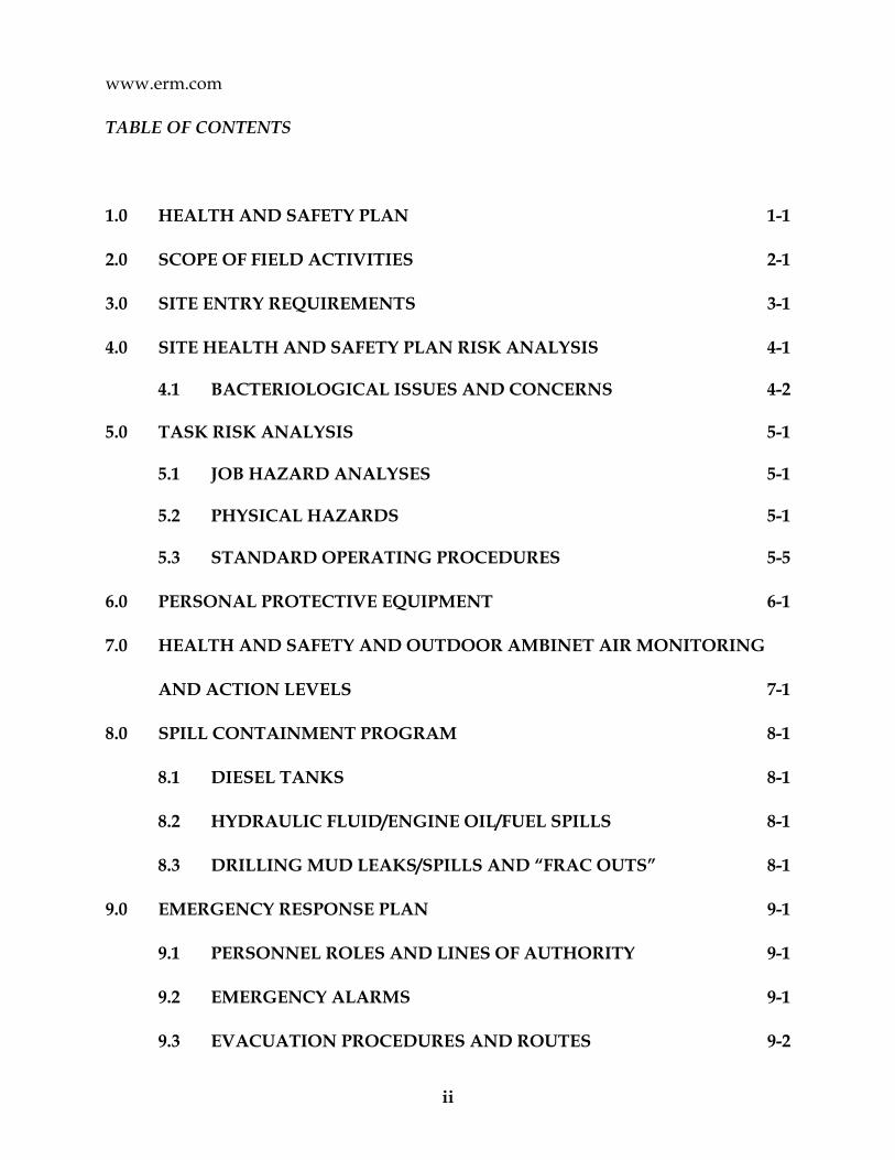
TABLE OF CONTENTS
1.0 HEALTH AND SAFETY PLAN 1-1
2.0 SCOPE OF FIELD ACTIVITIES 2-1
3.0 SITE ENTRY REQUIREMENTS 3-1
4.0 SITE HEALTH AND SAFETY PLAN RISK ANALYSIS 4-1 4.1 BACTERIOLOGICAL ISSUES AND CONCERNS 4-2 5.0 TASK RISK ANALYSIS 5-1 5.1 JOB HAZARD ANALYSES 5-1 5.2 PHYSICAL HAZARDS 5-1 5.3 STANDARD OPERATING PROCEDURES 5-5
6.0 PERSONAL PROTECTIVE EQUIPMENT 6-1
7.0 HEALTH AND SAFETY AND OUTDOOR AMBINET AIR MONITORING
AND ACTION LEVELS 7-1
8.0 SPILL CONTAINMENT PROGRAM 8-1
8.1 DIESEL TANKS 8-1
8.2 HYDRAULIC FLUID/ENGINE OIL/FUEL SPILLS 8-1
8.3 DRILLING MUD LEAKS/SPILLS AND “FRAC OUTS” 8-1
9.0 EMERGENCY RESPONSE PLAN 9-1
9.1 PERSONNEL ROLES AND LINES OF AUTHORITY 9-1
9.2 EMERGENCY ALARMS 9-1
9.3 EVACUATION PROCEDURES AND ROUTES 9-2

iii
9.4 RESPONDING TO EMERGENCIES 9-2
9.5 REPORTING EMERGENCIES 9-3
9.6 RESTARTING WORK FOLLOWING AN EMERGENCY 9-3
9.7 EMERGENCY CONTACTS 9-3
10.0 MANAGEMENT AND INVESTIGATION OF INCIDENTS 10-1
10.1 UNSAFE ACT AND UNSAFE CONDITION REPORTING & INVESTIGATION 10-1
10.2 NEAR MISS REPORTING & INVESTIGATION 10-1
10.3 INCIDENT REPORTING & INVESTIGATION 10-2
10.3.1 Standard Incident Investigation 10-2
11.0 EMERGENCY PHONE NUMBERS 11-1
12.0 ACKNOWLEDGMENT 12-1
ATTACHMENTS
A GREENPAC CONSTRUCTION SAFETY MANUAL
B JOB HAZARD ANALYSES
C JOB HAZARD ANALYSES (BLANK FORM)
D APPLICABLE STANDARD OPERATING PROCEDURES
E EXCAVATION POLICY AND PROCEDURES
F MAP AND DIRECTIONS FOR HOSPITAL
G DAILY SAFETY MEETING FORM
H UNSAFE ACT, AND UNSAFE CONDITION REPORT FORM
I NEAR REPORTING & INVESTIGATION FORM
J INCIDENT REPORTING & INVESTIGATION FORM

iv
K NYS DEC COMMUNITY AIR MONITORING PROGRAM

ERM 1-1 HASP-APRIL 2011
1.0 HEALTH AND SAFETY PLAN Environmental Resources Management (ERM) has prepared this Health and Safety Plan (HASP) for the BCP RI Implementation Plan work being conducted at the Greenpac Mill, Former # 2 Mill facility located at 4001 Packard Road in Niagara Falls, New York (the Site). This HASP is a supporting document to the BCP RI Implementation Plan. This HASP applies to ERM personnel involved with the above mentioned Site investigation activities. This HASP will also be reviewed by ERM’s sub-contractor personnel, who will be required to comply with the health and safety protocols outlined in the document. However, each sub-contractor will be responsible and held accountable for the health and safety and actions of their employees.
Greenpac requires that all Site contractors shall review and confirm that they have read Greenpac Construction Safety policies and procedures and provide signed documentation that they understand and agree to comply with policies and all Federal, State and Local Government safety regulations. Greenpac also requires that all employees receive site specific orientation training that covers facility specific Health and Safety information and procedures. ERM and its subcontractors must complete their review and confirmation of their understanding and conformance to Greenpac Construction Safety Policies before entering the Site.
Greenpac requires that ERM employees and subcontractor employees must pass a drug screening urine test and receive site-specific safety orientation training covering facility specific Health and Safety information and procedures prior to be allowed on site.
A copy of the Greenpac Construction Safety manual is included as Attachment A.
In addition, ERM will conduct an initial project kick-off meeting on the first day of field activities, along with daily tailgate meetings at the beginning of each day of field work, during which health and safety items will be reviewed. These daily tailgate meetings will be attended by ERM personnel, Greenpac personnel, and sub-contractor personnel who will be in the field on that given day. The daily safety meeting will include a discussion of the following health & safety-related topics, among others:
Who is doing what, where, and how; The potential for overlapping site operations;

ERM 1-2 HASP-APRIL 2011
Changes to the HASP or JHAs;
Discussion of recent incidents or safety observations; and
Comments from the project personnel.
The meetings will be documented on the Daily Safety Meeting form found in Attachment G.
The procedures set forth in this HASP are designed to minimize the risk of exposure to chemical substances and physical hazards that may be present at the Site. These procedures generally conform to applicable federal, state and local regulations, including Occupational Safety and Health Administration (OSHA) requirements governing activities at hazardous waste sites and the requirements in 29 CFR 1910.120.
Specific practices and procedures, including the level of personal protective equipment, are based on a review of currently available information for the Site.
ERM has fulfilled the requirements of a Hazardous Communication Program as specified in 29 CFR 1910.120.
Every potential safety hazard associated with this investigation may not be predicted. This HASP does not attempt to establish rules to cover every contingency that may arise, but it does provide a basic framework for the safe completion of field activities and plans for reasonable contingencies. The procedures provided herein are to be used on-Site by ERM employees.

ERM 2-1 HASP-APRIL 2011
2.0 SCOPE OF FIELD ACTIVITIES
ERM will.
Major tasks to be performed by ERM personnel and/or ERM Contractors include the following:
Advancing Borings at specific locations that have been selected by
Greenpac and the NYS DEC; Greenpac has had the site surveyed and used a third party firm to
conduct investigations of subsurface buried utilities and approximate locations of underground tanks, vaults, piping systems, storm water, sanitary waster piping systems, etc;
ERM may have to use another firm NY Leak Detection Services for
additional subsurface investigations and clearance activities and may have to hand clear specific locations to a least 4 ft, based on site conditions and locations of underground utilities and structures;
Environmental media (soil/ground water) sampling;
Collection of soil samples in electrical transformer station will be
conducted during an electrical outage being performed by client. After de-energization has been completed by National Grid and both National Grid and the client s’ electrical subcontractor have placed their lock and tags on the electrical transformer substation lockout locations, ERM will place their locks and tags at the same lockout locations while they are conducting the sampling in the electrical transformer station fenced enclosure;
Excavation of contamination soil from the Site and transport offsite
for treatment and disposal;
Each of the tasks above has a Job Hazard Analysis (JHA) prepared for it. JHAs are further described in Section 5.1, below.
A detailed description of the field activities that will be conducted as part of this investigation is provided in the BCP RI Implementation Plan.

ERM 3-1 HASP-APRIL 2011
3.0 SITE ENTRY REQUIREMENTS
The Field Team Leader (FTL)/Site Safety Officer (SSO) will act in a supervisory capacity over ERM employees who participate in the field activities specified in this work plan. The FTL/SSO is responsible for ensuring that ERM Health and Safety responsibilities are carried out in conjunction with field activities. As part of these responsibilities, the FTL/SSO will distribute the HASP to field team personnel and discuss the HASP prior to the start of field activities. Field personnel will sign the “Acknowledgement” presented as Section 9, verifying that they have read and are familiar with the contents of this HASP. Sub-contractor personnel will also be asked to sign the “Acknowledgement” form indicating that they are familiar with the protocols outlined in the HASP.
NOTE: A personnel sign-in sheet will also be posted at the FTL’s work station onsite, along with a copy of this HASP.
Training
ERM and sub-contractor personnel that will be conducting sub-surface activities (i.e., drilling) at the Site will have completed training requirements for hazardous waste site operations in accordance with OSHA 29 CFR 1910.120 (e)(1)(2)(3) or be certified by their employers as having equivalent training or experience.
ERM personnel and ERM subcontractors will have reviewed the Greenpac Construction Safety Manual, completed the Greenpac acknowledgement and agreement form prior to mobilizing to the Site.
ERM personnel and ERM subcontractors will receive facility and site specific orientation training prior to enter the work areas of the Site.
Medical Surveillance
ERM and sub-contractor personnel that will be conducting sub-surface activities (i.e., drilling) at the Site must have completed appropriate medical surveillance as required by OSHA 29 CFR 1910.120(f).

ERM 3-2 HASP-APRIL 2011
Respirator Fit Test
ERM and sub-contractor personnel that may be required to use a negative pressure air purifying respirator while on-Site must have successfully passed a quantitative fit test in accordance with OSHA 29 CFR 1910.1025 or 1926.58 within the previous 12 months. Employees will be permitted to wear only those brands and models of respirator for which a fit test has been successfully performed.
At this time, it is not anticipated that respirator use will be required.
It is anticipated that general ventilation via outdoor ambient air movement and dilution will be adequate to minimize chemical exposures levels below applicable exposure limits in the event that a potential chemical exposure level approaches the action level of the chemical of concern.

ERM 4-2 HASP-APRIL 2011
4.0 SITE HEALTH AND SAFETY PLAN RISK ANALYSIS
Based on historical processes that have occurred at the Site, the main groups of chemicals that may be encountered during work activities are listed below.
Ground water, surface soil samples and excavation soil may contain detectable concentration levels of various VOCs, SVOCs, metals, and pesticides;
VOCs are the major group of chemicals that may be present in potentially hazardous concentrations in the breathing zone during investigation activities. Since the field activities involve subsurface disturbance for short periods of time and excavation of soil potentially containing various concentration levels of chemicals, metals, or pesticides, excavation activities may potentially generate the release of VOCs in vapor form and airborne dust particles containing various types and concentration levels of various VOCs, SVOCs, metals and pesticides with inhalation being the major pathway of concern. This HASP is primarily designed to protect individuals against exposure to these aforementioned compounds during the field activities. Risk posed by hazards of the on-site chemicals will be controlled by minimizing worker contact with these groups of chemicals.
4.1 BACTERTILOGICAL ISSUES AND CONCERNS Sanitary waste has been transported from the facility through underground sanitary waste piping systems treatment for off-site treatment and disposal. As such, there is a potential that soil samples collected adjacent to these piping systems may have a sanitary waster component and as a result there is a risk of employee exposure to bacteriological agents such as Escherichia coli, Micrococcus, Staphylococcus aureus, Streptococcus, Salmonella, and many others. In addition, there is the concern for viral diseases such as Bacteremia, Pneumonia, skin infections, typhoid fever, dysentery, etc.

ERM 4-2 HASP-APRIL 2011
Therefore, when ERM employees have the potential to have incidental contact with soil samples that may contain sanitary water residual, these employees should be wearing the appropriate PPE, such an inner layer of Nitrile gloves, long sleeve clothing and appropriate face and eye protection. If accidental contact does occur with soil or groundwater that may contain sanitary water, these employees should cease work activities and proceed to remove their PPE, clean and sanitize their hands, arm and face surfaces and then put on clean PPE and proceed with work activities.

ERM 5-1 HASP-APRIL 2011
5.0 TASK RISK ANALYSIS This hazard assessment identifies the general hazards associated with specific Site operations and presents an analysis of documented or potential hazards existing at the Site. Every effort must be made to reduce or eliminate these hazards. Those hazards that cannot be eliminated must be guarded against by use of engineering controls and/or personal protective equipment.
5.1 JOB HAZARD ANALYSES
Prior to initiating any new project activity or when there is a change in site conditions, the SSO will assist project team members in completing a Job Hazard Analysis (JHA). The JHA will list the hazards associated with the project activity as well as associated control strategies.
JHAs for the tasks listed in Section 2.0, are located in Attachment B and a blank copy of the JHA form are located in Attachment C.
5.2 PHYSICAL HAZARDS
Liquid Transfer
Based on field conditions, liquid transfer and/or handling may occur at the site during sampling activities (i.e., discharge of decontamination water or purge water into drums). During liquid handling operations that involve potential contact with skin, appropriate personal protective equipment will be utilized (e.g. gloves, etc.) as applicable.
Drum Handling
Based on field conditions, drum handling may occur at this site (i.e., soil cuttings, temporary storage of decontamination water). If necessary, the movement and opening of drums will be done in accordance with 29 CFR 1910.120(j).
Cold Stress
When the temperature falls below 40° Fahrenheit (F), cold stress protocol shall be followed. Employees must be supplied with adequate clothing to maintain body core temperature. To minimize the potential for hypothermia, a heated area outside the decontamination area will be available to Site workers during breaks.

ERM 5-2 HASP-APRIL 2011
Heat Stress
When the temperature exceeds 80° F, and personnel are wearing protective clothing, a heat stress-monitoring program shall be implemented as appropriate. Employees shall have access to break periods and drinking water as necessary. The signs of heat stress disorders are described below. Heat Cramps
Heat cramps are caused by heavy sweating and inadequate electrolyte replacement. Signs and symptoms include muscle spasms and pain in the hands, feet, and abdomen.
Heat Exhaustion Heat exhaustion occurs from increased stress on various body organs. The signs and symptoms include: Pale, cool, moist skin; Heavy sweating; and, Dizziness, nausea, fainting.
Heat Stroke
Heat stroke is the most serious form of heat stress, and should always be treated as a medical emergency. The body's temperature regulation system fails and the body temperature rapidly rises to critical levels. Immediate action must be taken to cool the body before serious injury or death occurs. Signs and symptoms of heat stroke include: Red, hot, unusually dry skin; Lack of, or reduced, perspiration; Nausea; Dizziness and confusion; Strong, rapid pulse and confusion; and, Coma. Eye Protection Operations involving the potential for eye injury, splash, etc. must have approved eye wash units locally available as per 29 CFR 1910.151(c).

ERM 5-3 HASP-APRIL 2011
Vehicular Traffic Vehicular traffic associated with routine site operations and distribution activities, and excavation and transport of contaminated soil at the Site may pose a significant hazard to project personnel. Powered vehicles inside the facility include forklifts. Powered vehicles outside the facility include tractor-trailers and other motor vehicles. Precaution should be taken when Site activities make it necessary to work in or near active excavation areas and in or near high travel areas. High-visibility vests will be required for personnel will be working in such areas. Sampling Hazards Field activities will consist of collecting soil and ground water samples for analysis and evaluation. The hazards of this operation are primarily associated with the sample collection methods and procedures utilized. Standard methods and procedures that will be utilized for sampling activities are described in the Quality Assurance Project Plan. Of these specific procedures, none present hazards that are unique to sampling.
Overhead and Buried Utility Hazards Utility lines, both above and below ground, may pose a safety hazard for
Site personnel during soil boring or other heavy equipment operations. If overhead utilities have been identified as a hazard, the equipment operator must maintain a safe clearance between the lines and the equipment at all times during work operations. High voltage lines require greater clearance distances. As a safe work practice, equipment operators will maintain at least a 20-foot clearance between equipment and power lines or other energized sources unless the source is greater than 350 KV, in which case 29CFR 1910.180(j) (ii) must be applied. Overhead utility lines are present near the south end of the excavation. It is anticipated that all excavation activity will occur more than 20-feet away from the overhead utility lines. The location of buried utilities lines in and around the excavation area has been assessed by the site. A request for subsurface utility clearance was filed through Dig Safely New York. Greenpac facility personnel assisted ERM by estimating the location of underground utilities in the excavation area. ERM’s sub-contractor, New York Leak Detection (NYLD) will be providing additional screening services for the boring locations as required at the time of actual boring activities using ground penetrating radar or other technologies/equipment as required based on Site conditions.

ERM 5-4 HASP-APRIL 2011
ERM has performed the following tasks as part of the ERM Subsurface Clearance Guidelines:
ERM will complete a Subsurface Clearance Checklist ; ERM will utilize site specific and information provided by Dig
Safely NY to identify underground pipelines, utility lines, and fiber optic cable;
ERM has contracted with New York Leak Detection Services to be on-site and provide additional screening services as required for each specific boring location;
ERM will be contacting site personnel to identify process specific underground piping systems, storm water, sanitary waste water piping systems etc and any other obstructions;
In the event that a subsurface utility is encountered during work activities, evacuate the work area and contact Greenpac Security personnel at the number provided in Section 8.0.
Drill Rig Operation Drill rigs present multiple hazards while in operation. Excessive noise, boom raising, lowering and swing, cable and hook damage and operator error may result in injuries. To minimize potential accidents, the following safety measures should be required for all drilling operations. The drilling subcontractor is responsible for the health and safety of its personnel, equipment, and operations.
Operators (drillers) of equipment used on site will be familiar with the requirement for inspection and operation of such equipment. The drilling subcontractor is responsible for ensuring proficiency in safe operation the equipment;
Drilling shall be performed from a stable ground position. If
unable to locate on level ground, the drill rig shall be appropriately checked, blocked, and braced prior to the derrick being raised;
A competent person employed by the drilling subcontractor
competent in drilling safety shall make daily inspections of the drilling area. The inspector shall note the safety of the drilling area and confirm the location of all utilities;

ERM 5-5 HASP-APRIL 2011
Before drilling, the existence and location of utility lines (electric and gas) will be determined by the Site owner, Dig Safely New York, and New York Leak Detection Services. This will be done, if possible, by contacting the appropriate utility company and/or client representative to mark the location of the lines. If the knowledge is not available, an appropriate device, such as a cable-avoiding tool, will be used to locate the service line(s);
If flammable or combustible materials are encountered, no ignition
sources are permitted if the ambient airborne concentration of flammable vapors exceeds 10 percent of the Lower Explosive Limit (LEL) during drilling activities. A combustible gas indicator supplied by the driller will be used as needed to make this determination in conjunction with constituent-specific LEL percentages;
Operations must be suspended and the area evacuated if the
airborne flammable vapor concentration reaches 10 percent of the LEL in an area of an ignition source, such as an internal combustion engine or an exhaust pipe;
Combustible gas readings of the general work area will be obtained
as required based on the HSO's determination; If drilling equipment is located in the vicinity of overhead power
lines, a distance of 20 feet must be maintained between the lines and any point on the drill rig;
Daily inspection of the drill rig and associate machinery must be
conducted and documented by the driller prior to each day’s operation of the rig. Inspections shall include examination of wire, rope, hydraulic lines, etc;
In the event that repairs to the drilling rig derrick are required, all
personnel climbing the derrick to effect such repairs must wear a restraint system, including parachute harness and lifeline, to prevent an accidental fall.
Excavation of Contaminated Soils
The excavation work at the former No. 2 Mill facility site will be conducted as detailed below, (see Attachment E for additional information):

ERM 5-6 HASP-APRIL 2011
The equipment, materials and supplies necessary to complete the work will be mobilized to the Site;
ERM will conduct on-site outdoor ambient air monitoring consistent with the requirements of the NYSDOH Community Air Monitoring Program (CAMP) located in Attachment K;
All excavated soil will be handled as a potentially hazardous waste and transported as for off-site disposal;
Confined Space Entry
ERM will not be performing any Permit Required Confined Space Entry activities at the Site.
5.3 STANDARD OPERATING PROCEDURES
ERM has Standard Operating Procedures (SOPs) that define the minimum requirements for controlling potential hazards related to the work and surroundings. SOPs are referenced as appropriate on the JHA form.
Copies of the SOPs that have been identified as pertinent to the hazards inherent in the work for this project have been included in Attachment D. These SOPs will be used to guide the development of JHAs by ERM personnel and ERM Contractors.

ERM 6-1 HASP-APRIL 2011
6.0 PERSONAL PROTECTIVE EQUIPMENT
The following is a brief description of the personal protective equipment that may be required during various phases of the project. The USEPA terminology that will be used for protective equipment includes Level D and Level C.
Level D protection shall be used when:
The atmosphere contains no known hazard.
Work functions preclude splashes, immersion, or the potential for unexpected inhalation of, or contact with, hazardous concentrations of any chemicals.
Level D protective equipment at a minimum shall consist of:
• Standard work uniform or coveralls.
• Reflective vest.
• Safety-toe work boots.
• Gloves as needed.
• Safety glasses.
• Hard hat.
Additional safety equipment that may be required for specific tasks includes:
• Chemical-resistant aprons.
• Dust/mist disposable mask (HEPA rated as specified in 1910.1025).
• Goggles.
• Face shields.
• Five-minute escape device.
• Welders goggles or shields.
• Hearing protection.
Level C protection shall be used when:
The types and concentrations of air contaminants are known and an air-purifying respirator (APR) capable of protection is available.
The substance has adequate warning properties and all criteria for the use of an APR are met.

ERM 6-2 HASP-APRIL 2011
Greater than 5 ppm up to 25 ppm of unknown organic vapors above background levels may be encountered.
Level C protection at a minimum shall consist of:
Chemical-resistant coveralls (Tyvek).
Steel-toe and shank work boots with chemical resistant over boots.
Disposable inner and outer gloves (Nitrile).
APR with full-face mask with appropriate canisters or cartridges. Respiratory protective equipment shall be NIOSH-approved, and use of this equipment shall conform to OSHA 29 CFR 1910.134 requirements.
Hard hat.
All joints taped with duct tape.
Activity Specific Levels of Protection
The required level of protection is specific to the activity being conducted. At this Site, the anticipated levels of protection are as follows:
ACTIVITY INITIAL LEVEL OF
PROTECTION SPECIAL REQUIREMENTS
Soil and ground water sampling.
Excavation and loading of trucks for transport
Level D
Level D
Monitor breathing zone for vapor phase VOCs above background levels.
Monitor breathing zone for vapor phase VOCs above background levels.
Safety Equipment
A first aid kit containing first aid items for minor incidents only, a fire extinguisher, and temporary eye wash station are maintained in each ERM vehicle.

ERM 7-1 HASP-APRIL 2011
7.0 HEALTH AND SAFETY AND OUTDOOR AMBIENT AIR MONITORING AND ACTION LEVELS
ERM will conduct on-Site air monitoring consistent with the requirements of the NYSDOH Community Air Monitoring Program (CAMP) provided in Appendix K. In accordance with the CAMP, air monitoring stations equipped with a photoionization detector (PID) for field measurement of VOCs, and a MiniRAE dust monitor will be established at the downwind perimeter of the work area to monitor for particulate emissions (dust) from the excavation activities. An upwind dust monitor will also be provided. Readings will be collected approximately every 15 minutes and recorded.
In addition, a PID and dust monitor will be used within the work zone to monitor for potential worker exposure and satisfy the requirements of the HASP.
According to 29 CFR 1910.120(h), periodic air monitoring shall be used to identify and quantify airborne levels of hazardous substances and health hazards in order to determine the appropriate level of employee protection needed at the Site.
Routine air monitoring at a minimum shall be conducted:
When work begins on a different portion of the Site;
Contaminants other than those previously identified are being handled;
Excavation activities are initiated and on-going;
Employees are handling leaking drums or containers or working in areas with obvious liquid contamination;
Periodic Air monitoring will consist at a minimum of the criteria listed below. Air monitoring instruments will be calibrated and maintained in accordance with the manufacturer's specifications.

ERM 7-2 HASP-APRIL 2011
Instrument Compound Frequency of Monitoring
Action Level Action
PID or FID VOCs Continuous PID reads 5 ppm above the background level sustained in the breathing zone for 15 minutes
Stop work, vent area, and then continue to monitor.*
PID reads above 25 ppm above the background level sustained in the breathing zone for 15 minutes.
Stop work. Contact Project Manager for further instruction.
* If outdoor natural ventilation of area is not sufficient to cause VOC readings to drop below the 5 ppm action level, work in that location shall be stopped, and workers should vacate the area. Additional engineering controls may be employed to mitigate the elevated readings during investigation. If other engineering controls are not adequate to mitigate the elevated VOC readings, the Project Manager and FTL, along with P&GM personnel, will discuss the use of Level C PPE to complete the boring.

ERM 8-1 HASP-APRIL 2011
8.0 SPILL CONTAINMENT PROGRAM The spill contamination program for this project will involve the use of preventative measures in order to reduce the potential for environmental releases. These preventative measures will include the following:
Equipment inspection; Staging equipment on containment pads;
General housekeeping practices;
If project activities involve the use of drums or other containers, the drums or containers will meet the appropriate DOT regulations and will be inspected and their integrity assured prior to being moved. Operations will be organized so as to minimize drum or container movement. Drums or containers that cannot be moved without failure will be over packed into an appropriate container. ERM personnel and subcontractors will comply with the applicable facility specific environmental policies.
8.1 DIESEL TANKS Diesel storage tanks will not be necessary for this project.
8.2 HYDRAULIC FLUID/ENGINE OIL/FUEL SPILLS
In the event of an unexpected release of hydraulic fluid, engine oil, gasoline or diesel fuel, the release material will be absorbed with sorbent pads, which will be placed in a designated drum for disposal. Impacted soil will be excavated and placed on plastic sheeting and covered until characterization and/or disposal can be arranged.
8.3 DRILLING MUD LEAKS/SPILLS AND “FRAC OUTS”
A frac out is defined as a release of drilling fluid that occurs when the fluid migrates to the surface instead of returning through the borehole into the returns box. These types of incidents are not expected to occur during the advancement of borings.
ERM 9-1 HASP-APRIL 2011
9.0 EMERGENCY RESPONSE PLAN This section describes possible contingencies and emergency procedures to be implemented at the site.
9.1 PERSONNEL ROLES AND LINES OF AUTHORITY The SSO has primary responsibility handling emergency situations. This includes taking appropriate measures to ensure the health and safety of site personnel and the public. The SSO will be responsible for evacuating any person and providing decontamination, and arranging for medical treatment or first aid for any person injured or requiring medical attention. Possible actions may involve the evacuation of personnel from the site area and ensuring that corrective measures have been implemented, appropriate authorities notified, and follow-up reports completed. If the SSO is not available, other ERM field staff will assume the SSO’s responsibilities. ERM and subcontractor personnel will assist as directed by the SSO in case of an emergency.
9.2 EMERGENCY ALARMS In the event that an emergency alarm sounds at the facility, ERM personnel and subcontractors will comply with the Greenpac facility specific emergency evacuation procedures as provided in employee orientation training.
9.3 EVACUATION PROCEDURES AND ROUTES
In the event that an emergency alarm sounds at the facility, ERM personnel and subcontractors will comply with the Greenpac facility specific emergency evacuation procedures as provided in employee orientation training. The nearest assembly point for the Former #2 Mill for ERM personnel and subcontractors is the guard building on north site of Site. In the event of an emergency requiring evacuation to an Assembly Point, the SSO will be responsible to account for the presence of all project team members and subcontractors on-site at the time of the emergency. When evacuating, it is important to be aware of the prevailing wind direction and evacuate upwind or crosswind.

ERM 9-2 HASP-APRIL 2011
9.4 RESPONDING TO EMERGENCIES
In the event an actual or suspected incident where personal injury or illness occurs, the SSO should take the following actions sequentially as listed:
Don appropriate PPE; Remove the exposed or injured person(s) from immediate danger;
Decontaminate affected personnel as appropriate;
Contact Greenpac Security to obtain ambulance transport to the
local hospital in the event of any injury or illness deemed to require medical surveillance or treatment; and
Evacuate other personnel until it is safe for work to resume.
9.5 REPORTING EMERGENCIES
At the earliest time practicable following the occurrence of the emergency situation, the SSO will contact the ERM PIC/PM and ERM H&S Coordinator to advise them of the situation. The PM will then be responsible for promptly informing the following parties about the emergency.
Injured/involved personnel’s supervisor; Partner-In-Charge; and
Client Contact;
In the case of an Incident, the SSO, with the cooperation of the ERM H&S Coordinator will promptly begin formal documentation of and investigation into the root cases of the Incident following the occurrence of the incident. This process is defined in Section 10, below.
9.6 RESTARTING WORK FOLLOWING AN EMERGENCY The SSO and Greenpac Security will determine when it is safe to resume work at the site following an emergency. Note that if there is any doubt regarding the safe condition of the area, work will not recommence until all safety issues are resolved. If the emergency was initialized by

ERM 9-3 HASP-APRIL 2011
Greenpac, facility personnel will contact the SSO when it is safe to recommence work activities.
9.7 EMERGENCY CONTACTS Contact information for emergencies is provided in the project personnel list in Section 11.
ERM 10-1 HASP-APRIL 2011
10.0 MANAGEMENT AND INVESTIGATION OF SAFETY EVENTS Safety events are occurrences or conditions that may contribute to or result in an injury, occupational illness or property damage. ERM seeks to learn from the investigation of the following types of safety events:
Unsafe acts and unsafe conditions; Near misses; and
Incidents (actual injury, illness or property damage);
Each type of event and the reporting / investigation required of it is described below. Note: The Greenpac Construction Safety Manual states the following: “Report all unsafe conditions, near misses and injuries – no matter how slight.”
10.1 UNSAFE ACT AND UNSAFE CONDITION REPORTING & INVESTIGATION All ERM and subcontractor personnel at the site should be vigilant to identify and correct Unsafe Acts and Unsafe Conditions that could lead to a Near Miss or an Incident. Not withstanding the Stop Work Authority described elsewhere, ERM and subcontractor personnel at the site should report the observation of an Unsafe Act or Unsafe Condition as soon as practicable to the SSO such that:
Additional correctives action can be taken; and Important lessons learned can be disseminated to the site team.
Documentation of the reported Unsafe Acts and Unsafe Conditions will be made on the form provided in Attachment H. The SSO will note and track all corrective actions to completion.
10.2 NEAR MISS REPORTING & INVESTIGATION
Near Misses have the potential to become Incidents, but for some fortunate reason do not. Even though a worker illness or injury or property damage does not occur, it is important to understand why Near Misses happen and what can be done at the job site to stop their recurrence. Thus, all site personnel should be vigilant to identify Near

ERM 10-2 HASP-APRIL 2011
Misses that could lead to an Incident. Site personnel should report the observation of Near Misses as soon as practicable to the SSO such that:
Appropriate additional corrective actions can be taken; and Important lessons learned can be disseminated to the site team.
Near Misses will be investigated within 24 hours of their occurrence. Documentation of the investigation of Near Misses, Unsafe Acts, and Unsafe Conditions will be made on the form provided in Attachment I. Root cause analysis will be performed to assess the apparent cause and identify corrective measures to be implemented to prevent re-occurrence. Part II of the investigation will be completed within three working days of the occurrence of the report. The SSO will track to completion the corrective measures identified during the investigation. The SSO will initiate verbal communications regarding the occurrence of the Near Miss to the parties listed in Section 11.
10.3 INCIDENT REPORTING & INVESTIGATION Incidents result in worker illness, injury, or property damage. Incidents should be reported as soon as practicable to the SSO. The SSO will initiate verbal communications regarding the occurrence of the Incident to the appropriate parties listed in Section 11.
10.3.1 Standard Incident Investigation For most incidents, the SSO will also begin documentation of the Incident using the ERM Incident Report & Investigation Form found in Attachment J. The form consists of two parts:
Part I, in which the facts of the Incident are gathered and Part II, in which the root causes of the Incident are identified and
actions are assigned to address those root causes; The SSO will complete a draft version of the Part I Investigation and will forward it to the PM and ERM H&S Coordinator within 24 hours of the occurrence of the Incident. The SSO, PM, and ERM H&S Coordinator will schedule Part II of the investigation and include project supervision (ERM, ERM Contractors, and the Client), the injured/involved employee(s). Root cause analysis will be performed to assess the apparent cause and identify corrective measures to be implemented to prevent re-occurrence. Part II of the investigation will be completed within three working days of

ERM 10-3 HASP-APRIL 2011
the occurrence of the Major Incident. The SSO will track to completion the corrective measures identified during the investigation.
10.3.2 Severe Incidents In the case of very severe incidents, such as dismemberment, fatalities or substantial property damage, the project management team should consult with ERM and ERM management to develop an appropriate investigation strategy, in cooperation with any outside entities that may be involved. In such cases, the Incident and root cause analysis will still be documented, though the standard ERM Incident Investigation & Report Form may not be appropriate for such purposes. This determination will be made on a case-by-case basis by the project management team.

ERM 12-1 HASP-APRIL 2011
11.0 EMERGENCY PHONE NUMBERS
Emergency phone numbers are provided below.
AGENCY/ORGANIZATION TELEPHONE
Fire Department 911
Police 911
Emergency Medical Services 911
Hospital 716-298-2249
Security must be notified first of any site emergency to allow emergency services access to the site.
ERM Syracuse Office
Project Director:
Project Manager:
ERM Health and Safety Officer: Ernest Sweet
(315) 445-2554
(315) (cell)
(315) 341 (cell)
(315) 256-5354 (cell)
Ambulance 911
Hospital: Mount St Mary’s Hospital
5300 Military Road Lewiston, NY 14092-1997 (716) 297-4800
Directions to the Hospital from the facility:
1. Head Northeast on Packard road towards Ferry Ave for 0.3 miles.
2. Take 1st right turn onto Niagara Falls Blvd and go 1.1 miles.
3. Turn left to merge onto I-190 N for 5.3 miles.
4. Take Exit 25A for NY-265 towards Lewiston-0.1 mile
5. Turn left at NY-265 N/Military Rd- 0.3 mile
Approximate Total Distance =7.1 miles

ERM 12-2 HASP-APRIL 2011
12.0 ACKNOWLEDGMENT
I have read this Health & Safety Plan, and I understand the material in it. I agree to follow all procedures outlined herein.
Name Company Date Signature

Attachment A Greenpac Contractors Manual
Greenpac Construction Safety Manual
DTP/Attachment A-Greenpac Construction Safety Manual (2) (3) (2)[1].doc • 4/14/11 • 1

TABLE OF CONTENTS
Section 1: SAFETY COMMITMENT POLICY AND GOALS...................... 4 1.1 Goals and Objectives ..............................................................................................4
1.2 Mission and Principles.............................................................................................4
Section 2: PROJECT SAFETY PLAN........................................................ 5 2.1 Management Commitment and Leadership.............................................................5
2.2 Safety Assessment..................................................................................................5
2.3 Training ...................................................................................................................6
2.4 Compliance and Enforcement .................................................................................6
2.5 Medical Case Management .....................................................................................6
2.6 Data Analysis...........................................................................................................7
2.7 Behavior-Based Safety............................................................................................7
Section 3: DRUG TESTING PROTOCOL .................................................. 9
Section 4: PROJECT SAFETY POLICIES and PROCEDURES............. 11 4.1 Contractor Safety Requirements ...........................................................................11
4.2 Education...............................................................................................................12
4.3 New Employee Orientation....................................................................................13
4.4 Safety Team ..........................................................................................................15
4.5 Site Self-Inspection Process/Safety Audits............................................................16
4.6 Work Hour Policy...................................................................................................17
4.7 Job Safety Planning...............................................................................................18 4.8 Toolbox Meetings ..................................................................................................19
4.9 Personal Protective Equipment .............................................................................20
4.10 Housekeeping and Sanitation................................................................................22
4.11 Ergonomics Program.............................................................................................24
4.12 Fall Protection........................................................................................................25
4.13 Steel Erection ........................................................................................................30
4.14 Cranes and Rigging...............................................................................................31
4.15 Personnel Hoisting ................................................................................................33
4.16 Man lift and Elevator Policy ...................................................................................36
4.17 Scaffold Use and Inspection ..................................................................................37
4.18 Ladder Safety ........................................................................................................41
4.19 Material Handling and Storage ..............................................................................42
4.20 Motor Vehicles and Mobile Equipment ..................................................................45
4.21 Excavation, Trenching and Shoring.......................................................................47
4.22 Confined Space Entry............................................................................................48
DTP/Attachment A-Greenpac Construction Safety Manual (2) (3) (2)[1].doc • 4/14/11 • 2

4.23 Electrical ................................................................................................................53
4.24 Electrical Lockout ..................................................................................................56
4.25 Valve Lockout ........................................................................................................57
4.26 Commissioning and Start-up Safety ......................................................................58
4.27 Concrete and Reinforcing Steel (Rebar)................................................................60
4.28 Welding and Cutting ..............................................................................................62
4.29 Burning Permits .....................................................................................................71
4.30 Hazard Communication .........................................................................................72
4.31 Tools and Equipment.............................................................................................74
4.32 Barricades .............................................................................................................78
4.33 Pneumatic Testing Procedure ...............................................................................79
4.34 Emergency Plans ..................................................................................................80
4.35 Fire Protection .......................................................................................................82
4.36 Explosives .............................................................................................................84
4.37 Abrasive Blasting...................................................................................................85
4.38 Tunneling...............................................................................................................87
4.39 Demolition..............................................................................................................88
4.40 Diving ....................................................................................................................89
4.41 Over-Water Work...................................................................................................90
4.42 Helicopter Use .......................................................................................................91
4.43 Office Safety ..........................................................................................................92
4.44 Travel Safety .........................................................................................................94
4.45 Site Security ..........................................................................................................96
4.46 Enforcement and Recognition ...............................................................................97
4.47 Incident Investigation Process ...............................................................................98
4.48 Return-to-Work/Light Duty Program ......................................................................98
Attachments Safety Start-up Checklist for New or Modified Equipment ...........................................100
Earthquake Preparedness Process .............................................................................103
Bomb Threat by Phone Checklist ................................................................................106
DTP/Attachment A-Greenpac Construction Safety Manual (2) (3) (2)[1].doc • 4/14/11 • 3

DTP/Attachment A-Greenpac Construction Safety Manual (2) (3) (2)[1].doc • 4/14/11 • 4
Section 1: SAFETY COMMITMENT POLICY AND GOALS Greenpac Company, particularly Greenpac Construction is committed to the principal that we have a moral and legal obligation to provide and maintain a safe and healthful work environment for all employees working on our projects. Greenpac believes that all incidents causing injury or property damage are preventable, and therefore we have adopted a “ZERO ACCIDENT” philosophy for all projects. All levels of management must be committed to this philosophy and never compromise or jeopardize the safety and health of any employee for any reason, including cost or schedule impact. 1.1 Goals and Objectives The objective of Greenpac is to ensure that all work performed on our projects is
consistent with safe work practices and in accordance with all federal, state, local, and company standards. Management is charged with the task of assuring this policy results in visible accident prevention efforts at every level of operation. Our goal is Zero, but to never exceed the following:
Recordable Incident Rate ............... 2.0DART Rate ..................................... 1.5Lost-Time Incident Rate ................. 0
These rates far exceed the construction industry average but are attainable when each
and every person is continuously instilled with the desire to have an accident-free workplace. All projects should strive to meet or exceed these goals.
1.2 Mission and Principles Our mission is to “drive our projects toward world-class safety performance through
management leadership, standard practices and correct use of data, as well as focus on greatest potential improvement.” These simple principles will guide and assist us in achieving our goals and objectives:
Safety is proactive, not reactive.
All incidents are preventable.
Our commitment to safety is based on a genuine caring for all employees.
Line management is responsible and accountable for the safety of employees under their control.
Every employee is personally accountable for their own safety.
Safety is a condition of employment.
All injuries or near-misses no matter how insignificant they may appear are to be reported in a complete and timely fashion to the Safety Department.

DTP/Attachment A-Greenpac Construction Safety Manual (2) (3) (2)[1].doc • 4/14/11 • 5
Section 2: PROJECT SAFETY PLAN Greenpac Construction will develop, administer and enforce a safety plan that incorporates all federal, state and local regulations as a minimum guideline. Management will be committed to placing the highest priority on the safety of every employee on-site and strictly abides by the rules and regulations contained in the following policy and procedure manual. We, as individuals, may not be able to prevent every incident that may occur on a job site, but by making this commitment to safety, we, as a company, will have done our part to provide a work site where there are no deaths, lost-time accidents, recordable injuries, or property damage. The success of Greenpac projects is contingent on the strict attention and adherence to the following basic elements: 2.1 Management Commitment and Leadership Management, from the top to the bottom, must be totally and thoroughly committed to the
safety of every individual working or visiting a Greenpac project site. This commitment must be evidenced by their knowledge of the safety standards and their ability to enforce these standards while advancing the concept that they genuinely care and are concerned about you as an individual. “Leadership Behaviors at World Class” is the single most important element of the Greenpac Safety Strategy. Active, involved and visible leadership is critical to achieving world-class safety results and reaching our company goals. Leaders provide direction and motivation, and through their direction and support, they will enable others to succeed.
2.2 Safety Assessment Management must be involved in the safety strategy of a project from the conceptual or
proposal stage to the very end. Each project will undergo a stringent hazard and operability study to identify safety issues and facilitate proper planning and preparation for their control. This may actually be classified as the first safety assessment, or pre-assessment. Follow-up safety assessments, as well as other costs associated with the safety process, should be considered during the cost of budget phase of the project. Members of the leadership team, other safety professionals or other project management personnel may conduct the assessment. The safety assessment process is intended to assess the effectiveness of the field safety program for construction projects. It will consider how effectively the recognized safety processes are being used and determine the impact on the workers through one-on-one interviews and field observations. The assessment should result in direct feedback to project management and should include well dons, opportunities for improvement and specific recommendations to improve overall safety effectiveness.
Each project must implement a self-assessment or audit program. The contractors will
conduct daily audits. Craft personnel from each contractor, along with the safety team, will conduct a weekly job site audit. The results of this audit will be distributed in writing to management and staff at the weekly staff meeting and will be made available to all employees.

DTP/Attachment A-Greenpac Construction Safety Manual (2) (3) (2)[1].doc • 4/14/11 • 6
2.3 Training Just as engineering technique and production philosophies change and require
continuous training, so do safety requirements. One of OSHA’s primary functions is to develop new training criteria to facilitate the development of an accident-free workplace. Greenpac Construction will require that their employees receive the latest and most up-to-date training available. We will require that contractors involved with our projects provide trained and competent employees. Continuous training in all aspects of the safety process is essential to providing a safe work environment.
Greenpac Construction Safety Manager will develop and administer a site-specific safety
orientation for the project. Every employee must complete this orientation prior to beginning work. Following the orientation, all employees should be knowledgeable of the safety process of the project and clear as to what is expected from them in order for this process to work. The project safety rules and regulations will be discussed in detail. All orientations and other training must be documented, and a verification of knowledge quiz must be completed.
Greenpac Construction Safety Manager may also develop other site-specific training that
may be required for the project (lockout, confined space, equipment, etc.). Contractors must comply with all OSHA-required training.
2.4 Compliance and Enforcement It is mandatory that all federal, state, local, and Greenpac standards are complied with by
all contractors and employees on Greenpac projects. The purpose of these standards and policies is to facilitate a safe work environment and to prevent incidents from occurring. Contractor management must commit to enforcing compliance, and everyone must understand that failure to comply will result in disciplinary action that may involve termination.
Cooperation with all government agencies is mandatory. Employees will assist with
investigations and provide legally requested information. Federal and state OSHA programs provide a consultation service. It is suggested that project management become familiar and involved in this process. It tends to establish rapport with our project and the local OSHA staff, and once they have visited our site, they will realize our wholehearted effort and commitment to the safety of our employees and become an invaluable asset to our safety process.
2.5 Medical Case Management The Greenpac Construction Safety Manager should conduct a diligent search in the
community to locate a physician that is familiar with all aspects of occupational injuries and is knowledgeable in the OSHA record keeping requirements. This doctor may serve as the project physician and the Medical Review Officer. All contractor safety managers should also introduce themselves and provide the doctor with information pertaining to their company. The physician will be made aware of our light duty and return-to-work programs. State Worker’s Compensation laws must be complied with when choosing or sending an employee to the doctor.

DTP/Attachment A-Greenpac Construction Safety Manual (2) (3) (2)[1].doc • 4/14/11 • 7
First-aid facilities and some medical equipment must be provided on site. All contractor
safety managers or contractor supervision must possess some ability to diagnose and treat minor injuries. Supervision must be CPR and first-aid certified. All contractor safety managers must be knowledgeable in case management and manage all injuries with the intent to return injured personnel to work as quickly as medically possible.
Greenpac management and all contractors will support the light duty or return-to-work
program. The essence of this program is that all personnel will be returned to meaningful jobs that comply with the treating physician’s directions. All parties should be clear on the return-to-work program details.
2.6 Data Analysis The accurate recording of incidents and compilation of data is essential to identify needs,
focus positive action and monitor progress to achieve our safety vision. This data enables us to project future problem areas and to adopt a proactive approach to our safety process. All near-miss incidents, injury-causing incidents and property-damage incidents must be investigated thoroughly. A system of reporting near-miss incidents that assures that management is made aware of these incidents must be established. The focus of these investigations should be to determine the cause and the corrective action required rather than to find someone to blame. All the information gathered during the scope of the investigation is entered into a Greenpac database for review and compilation. The information compiled by the investigation is made available to management and will assist in making sound decisions and assuring that our projects are closer to being accident free.
2.7 Behavior-Based Safety (BBS) If you ask ten safety professionals the definition of behavior-based safety, you will, no
doubt, receive ten different answers. It has been defined as “the application of principles and methods derived from the field of applied behavior analysis safety.” Simply put, it is a change in behavior created by self-analysis, rewarding feedback and positive reinforcement. Behavior-based safety programs should be employee driven and contain a continuous improvement process. The perception is that we can affect beneficial change in others by focusing on their behavior, asking them to focus on their own behavior and rewarding positive behavior.
Each of our sites will implement a customized BBS program. Since each facility is unique,
a site assessment that identifies strengths, deficiencies and cultural values must be conducted. This is accomplished by talking to employees and observing their behavior to determine their perception of safety. It is difficult to outline or provide specific guidelines to a behavior-based program, but they should contain these basic elements:
Worker-based or employee-driven
Trained observers
Observation criteria developed by workers
Data analysis

DTP/Attachment A-Greenpac Construction Safety Manual (2) (3) (2)[1].doc • 4/14/11 • 8
Positive reinforcement and rewards for positive behavior Employees will be introduced to the BBS theory during their initial orientation. All of the
policies, standards, rules, and regulations are for naught if we are unable to convince an employee to “buy into our safety program” and that a change in their behavior benefits them.

DTP/Attachment A-Greenpac Construction Safety Manual (2) (3) (2)[1].doc • 4/14/11 • 9
Section 3: DRUG TESTING PROTOCOL This protocol applies to all Greenpac projects to the extent that the law allows. As part of its safety responsibility, Greenpac will contractually demand that all contractor employees submit to a pre-employment drug test prior to beginning work, random drug testing (dates and times to be selected by Greenpac project management), post-accident or incident drug and alcohol test, and “for-cause” test (requested when there is reasonable suspicion that an employee may be under the influence of drugs or alcohol). Refusal to submit to a drug test when requested will result in immediate discharge. Greenpac projects will conduct on-site drug testing. The Greenpac Construction Safety Manager will contract with a certified laboratory to furnish all drug testing supplies and to conduct confirmation testing of all positive results. The on-site drug test will consist of a five panel drug screen for THC (marijuana), cocaine, methamphetamine, PCP, and morphine (synthetic opiates). The threshold or confirmation level for each of these is as follows:
Marijuana ............................... 15 Ng/mLCocaine.................................. 150
Ng/mLPCP ....................................... 25 Ng/mLMethamphetamine ................. 500
Ng/mLMorphine................................ 2000
Ng/mL Lab tests that confirm these levels will be reported as a positive result. The contractor safety manager or representative and the Greenpac Construction Safety Manager or designee will monitor the collection of specimens. All employees involved in the collection of specimens must be trained in the proper procedures. All federal, state, local, and laboratory collection procedures must be followed. Chain of custody forms and consent forms must be filled out and signed by the employee and the person collecting the specimen. Facilities must provide privacy for the individual submitting the specimen. It must be noted that specific gravity, pH and temperature requirements, as set forth by the laboratory, are required in order for a specimen to be valid. Specimens may also be tested for adulterants. If an employee is requested to submit a second specimen because of any problem with the first, this second specimen will be a witnessed specimen. If an on-site drug test indicates positive for any banned substance, the collector will explain (in privacy) to the employee the indications and advise him/her that they must leave the job site until the test results are confirmed by the certified laboratory. The specimen will then be sent to the lab immediately for confirmation. If the positive test is confirmed, the employee is forbidden to enter any Greenpac project sites or property for a minimum of six months. Some sites may also require a confirmation from the company medical review officer. If the test result is not confirmed or is reported by the laboratory to be negative, the employee will be notified immediately and will be allowed to return to the job.

DTP/Attachment A-Greenpac Construction Safety Manual (2) (3) (2)[1].doc • 4/14/11 • 10
If after the six-month period a contractor wishes to bring this individual onto Greenpac property or projects, the contractor must certify that the individual has two recent negative tests. One of these tests must have been within the last two days. The individual will also be subject to the pre-employment, on-site drug test. The contractor must also inform Greenpac of their plan to ensure that this individual will remain drug/alcohol free while working on Greenpac projects through random or some equally effective testing measures. A second positive drug test will result in the individual being forbidden to enter any Greenpac property or Greenpac project for a period of two years. A refusal to submit to a drug test when requested or an adulterated diluted or other invalid sample will result in the same consequences as a positive drug test. Any individual, who after being advised of the drug testing procedures, leaves the site for any reason will be considered to have refused the drug test. Any individual testing positive for a prescription drug must produce a valid prescription for that drug. The prescription must be specific to the individual and must not be out of date. The medical review officer (MRO) must review all positive tests for prescription drugs. Project management must implement a process for randomly selecting individuals for drug testing. This procedure should result in approximately ten percent of the workforce being selected for random testing once a month. Results of the test must be sent to the project safety manager via confidential means and must be treated with the utmost confidentiality. A designated representative of the contractor (human resources or project manager) will be notified of the results and the consequence.

DTP/Attachment A-Greenpac Construction Safety Manual (2) (3) (2)[1].doc • 4/14/11 • 11
Section 4: PROJECT SAFETY POLICIES AND PROCEDURES 4.1 Contractor Safety Requirements Purpose To ensure that all contractors employed with or for Greenpac abide by all safety rules and
place the highest priority on the safety of their employees. Scope The scope applies to all contractors, subcontractors and lower-tiered contractors
throughout the construction process. Expectations Contractors will develop, administer and enforce a safety plan that incorporates all
Greenpac, federal, state, and local regulations as the minimum guideline to provide a work site where there are no deaths, lost-time or recordable incidents.
Guidelines Contractors applying for work with Greenpac must have a companywide recordable
incident rate that does not exceed 4.0. Exceptions to this must be approved by the director of construction.
Contractors on site must:
Supply trained competent employees to perform their intended work activities and provide documentation to support the required training of employees (forklift, cranes, rigging, etc.).
Comply with all Greenpac safety policies and federal, state and local regulations; acknowledge, in writing, the receipt and understanding of the Greenpac project safety manual.
Supply to project safety manager a daily manpower report that includes the number of employees, absentees and any first-aid or doctor cases.
Provide the names and social security numbers of all intended new hires at least one day prior to hire date.
Provide brass numbers and name tags to be placed on the front of hard hats of all employees.
Report all incidents immediately to project safety manager and provide a written report within 24 hours of incident.
Participate in all project safety audits.
Ensure that all subcontractors and lower-tiered contractors meet all Greenpac contractor requirements.
Contractors with:
1 to 45 employees must have a safety representative or a supervisor that is also a safety representative on site
Over 45 employees must have a full-time safety professional on site

DTP/Attachment A-Greenpac Construction Safety Manual (2) (3) (2)[1].doc • 4/14/11 • 12
4.2 Education Purpose To ensure that all Greenpac project personnel and all contractor personnel are properly
trained in the safety regulations and procedures affecting their project and specific operations.
Scope The requirement to be knowledgeable in the safety regulations and procedures, which
affect the site and its personnel, apply to all projects and Greenpac project team members and contractor/ subcontractor personnel.
Expectations Greenpac project team members, site safety personnel and contractor/subcontractor
management personnel will be knowledgeable in the appropriate safety precautions to be taken during the anticipated work and the regulatory requirements applying to their specific operations.
Further, the aforementioned knowledge will be shared with all affected site personnel
through special meetings or toolbox meetings.
It is recommended that contractor supervision be trained and certified in CPR and first-aid.
Guidelines
Greenpac project staff must be knowledgeable in the safety procedures and regulations appropriate to their project.
Contractors and subcontractors must be knowledgeable in the safety procedures and regulatory requirements applicable to the project or the portions of the job for which they are responsible.
Foremen must be trained in the safety procedures in order to properly enforce and support the program. In addition to first-aid/CPR, the foremen must be trained in accident investigation, behavioral safety techniques and competent persons sessions (if they are to act as competent persons on the job).
Contractors must be attuned to OSHA training requirements, such as worker right-to-know, personal protective equipment, confined space entry, lockout/tag out, and more. There may also be job-specific exposures, which will require specialized training.
Contractors will be expected to educate their hourly employees as to the upcoming tasks on the project. This can typically be done through the toolbox meetings, but special meetings or training sessions may sometimes be necessary.

DTP/Attachment A-Greenpac Construction Safety Manual (2) (3) (2)[1].doc • 4/14/11 • 13
4.3 New Employee Orientation Purpose To provide a site-specific safety orientation for every new employee prior to beginning
work on any Greenpac project. Scope The orientation will be carried out at every project under Greenpac management. Expectations The project safety manager will establish a new employee safety orientation program.
This program will be site-specific and will include the Safety Processes and Procedures found in this manual. Every employee on the project will complete the orientation before beginning work on the site. The orientation will be completed in such a manner that all subjects are covered in an easily understood way (allowing for language differences as needed), and the orientation will be documented (including signatures of both the new employee and the person conducting the orientation). For extended projects, a refresher orientation will be required annually.
Orientation Topics All new employees must receive an orientation that provides information about the safety
program. Topics include: Personal Safety
Back injury prevention
Blood borne pathogen procedures
Drug and alcohol policy
Equipment issues
Fire prevention
Hazardous communications
Hearing conservation
Housekeeping expectations
Job hazard analysis
List of key contacts
Process safety management (PSM)
Personal protective equipment
Respiratory program
Sign-in procedure
Traffic, parking, pickup stations, and laydown areas General Safety Policies

DTP/Attachment A-Greenpac Construction Safety Manual (2) (3) (2)[1].doc • 4/14/11 • 14
Drug testing protocol
Electrical safety enforcement
Emergency preparedness/emergency numbers
Emergency weather and natural disaster procedures
Environmental procedures
Jewelry and dress policy
Lockout/tag out policy
Near miss/accident investigation procedures
Project safety rules
Radio and electronic equipment use
Safety meetings
Safety watches
Greenpac facility safety precautions Safety around Equipment
Articulating/suspended boom safety
Barricades
Demolition safety
Excavation and trenching
Fall protection
Floor, roof, wall, and platform opening hazards
Hand, air and electric tool use
Ladder safety
Mobile equipment safety
Radiography
Roofing work
Scaffolding and platforms
Signs and tags
Welding, cutting and burning safety

DTP/Attachment A-Greenpac Construction Safety Manual (2) (3) (2)[1].doc • 4/14/11 • 15
4.4 Safety Team Purpose To assemble a group of safety professionals that are able to work together in a proactive
manner to ensure the safety of every employee on the project. Scope All contractor safety managers assigned to the project. Expectations All safety managers will work together as a team under the direction of a designated
project safety director. They will share office space, when possible, and interact daily with meetings and discussions.
Guidelines
The Project Construction Manager will designate a Project Construction Safety Manager to administer the daily operations of the safety department and direct the safety team. The project safety director will administratively report to the Project Construction Safety Manager.
The Project Safety Manager will functionally report to the Project Manager and will be responsible for daily and monthly reports, establishing first-aid facilities and supplies, scheduling other safety managers, training, drug testing, office needs for safety managers, and the overall safety program for the project.
All Contractor Safety Managers will share office space, when possible, and work together as a safety team.
All Safety Managers will share responsibilities (training, orientation, drug testing, etc.).
Contractor Safety Managers will be responsible for investigating incidents involving their contractor personnel and furnishing the results of the investigation to the Project Construction Safety Manager. All Safety Managers on site may assist with investigations.
Safety managers must manage cases involving injuries to their employees, provide the care required, and provide as positive a result as possible.
Contractor safety managers are responsible for their company OSHA logs and reporting.
Safety Professionals must be willing to work together, regardless of their individual agendas, to ensure the success of the safety team and the safety of every employee on the project.

DTP/Attachment A-Greenpac Construction Safety Manual (2) (3) (2)[1].doc • 4/14/11 • 16
4.5 Site Self-Inspection Process/Safety Audits Purpose The purpose is to implement a safety self-inspection process for each project and thereby
identify and control potential safety hazards. Scope All Greenpac projects will develop and implement a safety self-inspection process
involving the contractors on the site. Expectations Project management will develop and implement a safety self-inspection or audit process
for operations on the site. This process will involve the craft employed on site. The system will also include development of controls for the identified issues and a documentation protocol to record the issues, their controls and corrective action taken.
Guidelines Guidelines are as follows:
Safety management will implement this procedure in a proactive manner.
All contractors will conduct daily audits of their work areas.
All contractors will be involved in a weekly job site audit.
The weekly audit will be led by a member of the safety team.
Both supervision and craft will be involved.
Both physical hazards and unsafe work practices will be sought out.
Inspection teams may need to involve affected personnel in the solutions to ensure “buy-in” and effectiveness.
Inspections are also an opportunity to recognize safe work habits! The results of this audit will be documented and made available to management and all
contractors and a copy sent to the Greenpac safety director.

DTP/Attachment A-Greenpac Construction Safety Manual (2) (3) (2)[1].doc • 4/14/11 • 17
4.6 Work Hour Policy Purpose The purpose is to prevent incidents resulting from work fatigue. Scope This policy applies to all Greenpac projects and all contractor and subcontractor
personnel on these sites. It will also apply to all shutdowns throughout the Greenpac system.
Expectations Greenpac project management teams are expected to enforce the described limits on
overtime work hours on all Greenpac projects and on all Greenpac shutdowns. All hourly employees are expected to abide by the restrictions applied herein. Guidelines
Project managers must schedule work hours so as to alleviate any employee from working too many hours and prevent employee fatigue.
This policy will apply to all shutdowns as well.
The maximum scheduled shift length will be twelve (12) hours. Exceptions by circumstance require project management approval.
No employee will be allowed to work in excess of sixteen (16) continuous hours without approval from the project manager.
All federal, state and local labor laws will be followed.
All work should be preplanned and proceed according to schedule, whenever possible.
The impact of this policy can be reduced by rotating craft or shutting down a job for a day in accordance with this work hour policy.
Greenpac project management must approve all overtime or extra work hours.
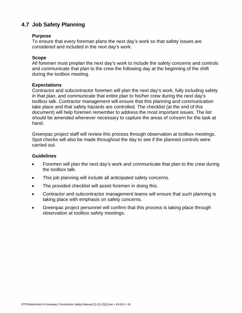
DTP/Attachment A-Greenpac Construction Safety Manual (2) (3) (2)[1].doc • 4/14/11 • 18
4.7 Job Safety Planning Purpose To ensure that every foreman plans the next day’s work so that safety issues are
considered and included in the next day’s work. Scope All foremen must preplan the next day’s work to include the safety concerns and controls
and communicate that plan to the crew the following day at the beginning of the shift during the toolbox meeting.
Expectations Contractor and subcontractor foremen will plan the next day’s work, fully including safety
in that plan, and communicate that entire plan to his/her crew during the next day’s toolbox talk. Contractor management will ensure that this planning and communication take place and that safety hazards are controlled. The checklist (at the end of this document) will help foremen remember to address the most important issues. The list should be amended whenever necessary to capture the areas of concern for the task at hand.
Greenpac project staff will review this process through observation at toolbox meetings.
Spot checks will also be made throughout the day to see if the planned controls were carried out.
Guidelines
Foremen will plan the next day’s work and communicate that plan to the crew during the toolbox talk.
This job planning will include all anticipated safety concerns.
The provided checklist will assist foremen in doing this.
Contractor and subcontractor management teams will ensure that such planning is taking place with emphasis on safety concerns.
Greenpac project personnel will confirm that this process is taking place through observation at toolbox safety meetings.

DTP/Attachment A-Greenpac Construction Safety Manual (2) (3) (2)[1].doc • 4/14/11 • 19
4.8 Toolbox Meetings Purpose To provide safety information and training to all project personnel. Scope This safety toolbox meeting requirement will apply to all contractor and subcontractor
personnel on each site. Expectations All contractors and subcontractors will hold toolbox safety meetings for all site personnel.
Safety and the daily work plan will be discussed for each craft or crew, and each meeting will be documented.
Guidelines
All contractors and subcontractors must hold a toolbox meeting.
Such meetings will be held daily at the beginning of each shift.
Toolbox meetings will include the crew or craftwork plan for the day, including safety. Safety should be the first subject on the list.
Primary safety subject material will be provided by contractor safety personnel.
Employees will be allowed to ask questions, make suggestions and voice complaints.
The project safety manager will select a weekly toolbox safety topic to be used by all contractors on site.
General operational content will be provided by the superintendent or foreman conducting the meeting. Supervision may have specific safety issues to add to the discussion.
All meetings will be documented on a form depicting the date, company or craft, superintendent’s name, primary topics, and the signature of all attendees.

DTP/Attachment A-Greenpac Construction Safety Manual (2) (3) (2)[1].doc • 4/14/11 • 20
4.9 Personal Protective Equipment (PPE) Purpose These guidelines provide minimum PPE requirements for all employees while working on a project. Scope These guidelines cover PPE requirements for all workers on a project. Expectations Each worker is responsible for knowing what is required and for wearing and maintaining
the proper safety equipment while working on the project. Project supervision has the responsibility to enforce the use and proper care of PPE by all
employees during the execution of the work, including termination for refusal to wear required PPE.
Guidelines
Pants must be full length. Shirts must have full or half sleeves (at least 6 inches). Sleeves must remain at this length, not rolled up. Clothing must not be torn, have holes worn in them or hang loose to the point that they may be caught in moving machinery. Dangling necklaces are not to be worn. Only stud-type earrings shall be worn — NO loop- or hoop-type earrings allowed. Employees having hair of shoulder length or longer must keep it secured such that it does not serve as a hazard.
Gloves will be worn as a minimum protection from hand injuries.
Each employee will be required to wear sturdy, high top, leather, hard-toed work boots meeting the protective requirement of ANSI Z41.1-196. Steel-toed tennis shoes, low-quarter shoes, or shoes or boots made of canvas material are not allowed.
All employees and visitors will wear hard hats meeting ANSI Z89.1-1969. Hard hats will be worn with the bill to the front (no hard hats to be worn backwards), unless performing welding operations. Hard hats are to be worn according to manufacturer specifications and should fit properly to allow the protection intended. No baseball-type caps to be worn under hard hats.
All employees and visitors must wear safety glasses with rigid side shields meeting the requirements of ANSI Z87.1-1968. When required by site conditions or while performing certain tasks (grinding, chipping, burning, etc.), employees will be required to wear full-face shields or goggles, in addition to safety glasses.
Hearing protection, consisting of earplugs or earmuffs acceptable to OSHA, will be worn by all potentially exposed personnel. The project manager and project safety manager will determine where and when hearing protection is required. This determination will be made in accordance with the mill policy and OSHA standard 1926.52.
Where required, employees will be issued escape respirators, which will be worn on the employee at all times.

DTP/Attachment A-Greenpac Construction Safety Manual (2) (3) (2)[1].doc • 4/14/11 • 21
Fall protection, consisting of a full body harness and double shock-absorbing lanyards, will be worn by all employees exposed to a fall of 6 feet or more.
When working in areas of high vehicular or equipment travel, employees will be required to wear a high-visibility vest.
There may be other safety or PPE requirements as a result of unique conditions on the project. The safety manager will identify any additional requirements as the need arises.
DTP/Attachment A-Greenpac Construction Safety Manual (2) (3) (2)[1].doc • 4/14/11 • 22
4.10 Housekeeping and Sanitation Purpose To maintain an orderly work site in an effort to reduce incidents involving fire, slips and
falls, puncture injuries, and ergonomic exposures. The purpose is to provide and maintain a sanitary work environment.
Scope A high standard of housekeeping will be maintained by all personnel and contractors
across the site. Expectations Material process waste will be controlled as produced. Materials will be properly stored in
lay down areas. Combustibles and flammables will be properly stored to prevent/control potential fire or container failure. Stairs and walkways will remain free of debris, materials and equipment.
Guidelines Housekeeping
Poor housekeeping is not acceptable on Greenpac Company projects. A clean project will be a daily priority. The construction manager will be responsible for developing and implementing adequate housekeeping for a project using these guidelines.
Supervisors will be responsible for keeping work areas clean. Clean-up will occur as the work is being done and will be part of daily task planning. On larger projects, a clean-up crew should be assigned to continuously clean up. (Having a clean-up crew does not alleviate any supervisor from keeping their work area clean.)
Dumpsters, trash skips and trash cans will be of adequate number and location to facilitate daily waste removal. All containers shall be marked as to their content.
Reusable scrap material shall be removed from the work area and stacked in neat piles. Nails and other sharp fastening devices shall be removed from lumber as it’s being dismantled.
Combustible waste, such as oily rags, shall be stored in a closed metal container and disposed of as hazardous waste.
Areas used by personnel for smoking, breaks and lunch shall be cleaned on a regular basis.
An area, such as electrical panels, safety disconnects, fire extinguishers, and emergency exits, shall be kept free of excess materials and debris.
Cords, leads and hoses shall be elevated a minimum of 8 feet whenever possible. When it is not possible to elevate, they shall be kept out of walkways, stairways, etc.
Sanitation

DTP/Attachment A-Greenpac Construction Safety Manual (2) (3) (2)[1].doc • 4/14/11 • 23
Where adequate permanent toilet facilities are not available, temporary toilets shall be supplied and maintained in accordance with local, state and federal regulations. Portable toilets shall not be kept inside buildings. Any employee involved in the destruction or damage of toilet facilities (including writing on walls) will be subject to immediate termination from the project.
An adequate supply of potable water shall be made available to employees on the job site. When permanent drinking water dispensers are not available, portable drinking water containers shall be made available. These containers shall be clearly marked “DRINKING WATER” and not used for any other purpose. They must have a tightly closed lid and be equipped with a spigot. The lid must be taped and dated to prevent tampering. Disposable cups and trash receptacle will be provided by each container. The use of pails, dippers, common cups, or drinking from spigot is prohibited. Water containers will be sanitized on a regular basis. Only clear, reinforced hoses, suitable for transferring potable water, may be used to clean and fill containers. Other water sources not suitable for drinking purposes shall be clearly marked “NON-POTABLE WATER.”
Care must be taken to ensure the cleanliness of ice machines and ice.
An adequate supply of hand-washing facilities must be available.

DTP/Attachment A-Greenpac Construction Safety Manual (2) (3) (2)[1].doc • 4/14/11 • 24
4.11 Ergonomics Program Purpose To minimize muscle strains, repetitive motion injuries and related ergonomic injuries. Scope All contractors and subcontractors on all projects will work to support ergonomic efforts. Expectations All contractors and subcontractors will support and enforce ergonomic procedures
wherever possible in an effort to reduce soft tissue injuries. Employees will follow ergonomic practices whenever possible.
Contractors will provide basic employee training through toolbox safety talks. Guidelines Guidelines are as follows:
All contractors and subcontractors will support ergonomic procedures whenever possible on all jobs.
Basic ergonomic training will be provided to all employees via toolbox talks.
Ergonomic areas to watch include the following: proper lifting procedures; using mechanical aids to lift materials; getting a coworker to assist with the lift; in storage areas, placing the most often used material at approximately waist height; using powered screwdrivers, nail guns, etc.; providing vibratory tools (e.g., concrete vibrators, chain saws, jack hammers), which are fitted with vibration-reducing equipment; providing vibration-absorbing gloves; using rebar jigs, which hold rebar “nests” at waist height; and placing raw material close to the point of insertion in the process.

DTP/Attachment A-Greenpac Construction Safety Manual (2) (3) (2)[1].doc • 4/14/11 • 25
4.12 Fall Protection Purpose To prevent falls on every project. Scope This protocol applies to all projects and will be site-specific to address all fall potentials at
each project. Expectations Every site will develop a site-specific fall prevention plan that will require 100 percent tie-
off at 6 feet and higher above the immediate working surface and/or other acceptable means of fall protection.
Guidelines The following guidelines will be administered on every Greenpac project:
Any employee in an elevated work area whose work places them outside any secured areas or where their work is to be performed on scaffolds, from boatswain chairs, structural steel, aerial lifts, or on any other working surface where they may be subject to a fall greater than 6 feet shall wear and use a full body harness, with two lanyards, and be tied off 100 percent of the time.
It will be the supervisor’s responsibility to ensure the safety of employees working above the 6-foot limit by using fall protection as needed.
At the time of hire and during safety meetings, each employee shall be made aware of their obligation to wear and use full body harnesses and associated equipment when the work task dictates. This policy will be adhered to strictly. Contractors must strictly enforce this policy, through discipline, if necessary. Any employee observed not using a full body harness as required will be subject to disciplinary action by their contractor employer.
Policy statements to this fact shall be posted throughout the job site and will be given to each employee to sign in his/her handwriting at the time of hire and will be placed in their personnel file for record.
Safety belts will not be used on Greenpac Company projects for fall protection. A Class III full body harness will be required.
Lifelines, full body harnesses and lanyards shall be used only for employees’ safeguarding. When any of these are actually subjected to in-service loading (as distinguished from static load testing), they shall be immediately removed from service and shall not be used again for employee safeguarding.
Lifelines shall be secured above the point of operating to an anchorage or structural member capable of supporting a minimum dead weight of 5400 pounds.
Lifelines used in areas where the lifeline may be subjected to cutting or abrasion shall be a minimum of 7/8-inch wire core manila rope or its equivalent. For all other lifeline applications, a minimum of 5400 pounds tensile strength shall be used. Wire rope of equivalent strengths may be substituted, but in no case shall standard wire

DTP/Attachment A-Greenpac Construction Safety Manual (2) (3) (2)[1].doc • 4/14/11 • 26
rope of less than 1/2-inch diameter be used. 3/8-inch airline cable that develops a tensile strength of 5400 pounds may be used.
Safety lanyards shall be a minimum of 1/2-inch nylon or equivalent with maximum length for a fall of no greater than 6 feet. The lanyard shall have a breaking strength of 5400 pounds. All lanyards shall have double-locking safety snaps.
All full body harness and lanyard hardware shall be drop-forged or pressed steel, cadmium-plated. Surfaces shall be smooth and free of sharp edges.
All full body harness and lanyard hardware, except rivets, shall be capable of withstanding a tensile loading of 5000 pounds without cracking, breaking or taking a permanent deformation. “Quick-release” lanyards shall not be used.
Exceptions
The provisions of this section do not apply at points of access, such as stairways, ladders, ramps, or when employees are on the roof only to inspect, investigate or estimate roof level conditions. Roof edge materials handling areas and materials storage areas shall be guarded as provided in this section.
Employees engaged in built-up roofing on low-pitched roofs less than 50 feet wide may elect to utilize a safety system without warning lines where the use of hot tar poses an additional hazard to workers.
Warning Line System for Roof Worker
Warning lines shall be erected around all sides of the work area.
When mechanical equipment is not being used, the warning line shall be erected not less than 6 feet from the edge of the roof.
When mechanical equipment is being used, the warning line shall be erected not less than 6 feet from the roof edge, which is parallel to the direction of mechanical equipment operation and not less than 10 feet from the roof edge, which is perpendicular to the direction of mechanical equipment operation.
The warning line shall consist of a rope, wire, or chain and supporting stanchions erected as follows:
The rope, wire or chain shall be flagged at not more than 6-foot intervals with high-visibility material.
The rope, wire or chain shall be rigged and supported in such a way that its lowest point (including sag) is no less than 39 inches from the roof surface and its highest point is not more than 45 inches from the roof surface.
After being erected, with the rope, wire or chain attached, stanchions shall be capable of resisting, without tipping over a force of at least 16 pounds applied horizontally against the stanchion, 30 inches above the roof surface, perpendicular to the warning line and in the direction of the roof edge.
The rope, wire or chain shall have a minimum tensile strength of 500 pounds and, after being attached to the stanchions, shall be capable of supporting, without breaking, the loads applied to the stanchions.

DTP/Attachment A-Greenpac Construction Safety Manual (2) (3) (2)[1].doc • 4/14/11 • 27
The line shall be attached at each stanchion in such a way that pulling on one section of the line between stanchions will not result in slack being taken up in adjacent sections before the stanchion tips over.
Access paths shall be erected as follows:
Points of access, materials handling areas and storage areas shall be connected to the work area by a clear access path formed by two warning lines.
When the path to a point of access is not in use, a rope, wire or chain, equal in strength and height to the warning line, shall be placed across the path at the point where the path intersects the warning line erected around the work area.
Material Storage and Handling
Employees working in a roof edge materials handling or materials storage area location on a low-pitched roof with ground-to-eaves height greater than 6 feet shall be protected from falling along all unprotected roof sides and edges of the area.
When guardrails are used at hoisting area, a minimum of 4 feet of guardrail shall be erected on each side of the access point through which materials are hoisted.
A chain or gate shall be placed across the opening between the guardrail sections when hoisting operations are not taking place.
When guardrails are used at bitumen pipe outlets, a minimum of 4 feet of guardrail shall be erected on each side of the pipe.
When safety harness systems are used, they shall not be attached to the hoist.
When fall restraint systems are used, they shall be rigged to allow the movement of employees only as far as the edge of the roof edge.
Materials shall not be stored within 6 feet of the roof edge unless guardrails are erected at the roof edge.
Leading Edge Control Zone
When performing leading edge work, project management shall ensure that a control zone be established according to the following requirements:
The control zone shall begin a minimum of 6 feet back from the leading edge to prevent exposure by employees who are not protected by fall restraint or fall arrest systems.
The control zone shall be separated from other areas of the low-pitched roof or walking/working surface by the erection of a warning line system.
The warning line system shall consist of wire, rope or chain supported on stanchions or a method which provides equivalent protection.
The spacing of the stanchions and support of the line shall be such that the lowest point of the line (including sag) is not less than 39 inches from the walking/working surface and its highest point is not more than 45 inches from the working/walking surface.
Each line shall have a minimum tensile strength of 500 pounds.

DTP/Attachment A-Greenpac Construction Safety Manual (2) (3) (2)[1].doc • 4/14/11 • 28
Each line shall be flagged or clearly marked with high visibility materials at intervals not to exceed 6 feet.
When positive means of fall protection, as described in OSHA, are not utilized, a safety monitor system, as described in OSHA 1926.500 (g) (iii), shall be implemented to protect employees working between the forward edge of the warning line and the leading edge.
Safety Monitor System
A safety monitor system may be used in conjunction with a warning line system as a method of guarding against falls during work on low-pitched roofs and leading edge work only.
When selected, the employer shall ensure that the safety monitor system shall be addressed in the fall protection work plan, including the name of the safety monitor(s) and the extent of their training in both the safety monitor and warning line systems, and shall ensure that the following requirements are met:
The safety monitor system shall not be used when adverse weather conditions create additional hazards.
A person acting in the capacity of safety monitor shall be trained in the function of both the safety monitor and warning line systems and shall: Be a competent person as defined in OSHA 1926.32(f). Have a control authority over the work as it relates to fall protection. Be instantly distinguishable over members of the work crew. Engage in no other duties while acting as safety monitor. Be positioned in relation to the workers under his/her protection so as to
have a clear, unobstructed view and be able to maintain normal voice communication.
Control zone workers shall be distinguished from other members of the crew by wearing a high-visibility vest only while in the control zone.
Inspection of Equipment
All lifelines, full body harnesses, lanyards, and associated hardware shall be inspected on arrival at the job site by a competent person. Employees will inspect equipment before and after each use for wear and possible damage due to use. Additionally, monthly inspections of full body harnesses, lanyards and associated hardware shall be done by a designated, competent person to ensure they have not been subject to damage and/or deterioration due to storage conditions and other factors that may reduce their strength characteristics. If any harness or lanyard, at any time, has a stress load placed on it, then it must be removed from service. An inspection report form shall be maintained on all full body harnesses, lifelines and lanyards, and will show the date inspected, the condition of the equipment, and the serial number for each full body harness. These reports shall be copied to the Greenpac Company safety manager. Proper color codes for the month shall be attached to harness and lanyards.

DTP/Attachment A-Greenpac Construction Safety Manual (2) (3) (2)[1].doc • 4/14/11 • 29
Color Code System Jan/Jun....................... Green Feb/Aug...................... Brown Mar/Sep...................... Gray Apr/Oct ....................... Yellow May/Nov ..................... Blue Jul/Dec ....................... Red

DTP/Attachment A-Greenpac Construction Safety Manual (2) (3) (2)[1].doc • 4/14/11 • 30
4.13 Steel Erection Purpose To ensure that all steel erection standards and guidelines are followed so that injuries
associated with steel erection will be prevented. Scope All contractors on Greenpac projects that may be involved in the erection of steel as
defined in OSHA subpart R steel erection standards. Guidelines
Prior to steel arriving on site, contractor supervision must provide Greenpac project management with a detailed work plan that includes staging, erection procedures and safety plan.
All employees involved in steel erection activities must utilize adequate fall protection if the work requires them to be at a level of 6 feet above a working surface. Absolutely no exception to the 6-foot fall protection rule.
Controlled decking zones will not be recognized. This work must be preplanned to allow for adequate personal fall arrest systems and/or fall restraint systems.
Steel laydown areas must be firm, properly graded, drained, and readily accessible to the work with adequate space for the safe storage of materials and the safe operation of the erectors’ equipment.
Climbing or sliding columns will not be allowed. Access and egress will be established as close to the work area as possible to reduce the travel required on “open” steel.
All safety equipment, aerial work platforms, static lines, temporary flooring, perimeter guarding, ladders, scaffolding, stairways, and falling debris protection must be on site and ready for use prior to the beginning of work.
OSHA subpart R steel erection standards effective in January 2002 will be strictly adhered to and enforced.

DTP/Attachment A-Greenpac Construction Safety Manual (2) (3) (2)[1].doc • 4/14/11 • 31
4.14 Cranes and Rigging Purpose To ensure safe use of cranes, rigging and related lifting equipment on each project. Scope All contractors and sites using cranes and rigging materials to complete construction will
abide by this protocol. Expectations All contractors using cranes and rigging equipment will work to ensure that all cranes and
lifting equipment are certified, properly inspected and maintained, and used safely throughout the course of the project. Detailed lift planning will be conducted to ensure that rigging and cranes are suitable to the conditions of the lift.
Guidelines Guidelines are as follows:
All cranes will be certified before being put into service on the site. Such certification will be documented.
All cranes must be inspected daily, monthly and annually. These inspections must be documented.
Contractors must provide documentation to Greenpac Site Manager and/or Safety Manager attesting to the competency and training of all crane operators and riggers. Training credentials must be up to date and valid.
All critical lifts (lifts that exceed 75 percent of the rated capacity of the crane, any lift that requires the use of more than one crane, lifts to be made in close proximity to electrical lines or other hazards, and/or any unusual lifts) will be thoroughly planned and documented in advance and coordinated with Greenpac project staff and all affected site personnel. Soil conditions will also be included in the critical lift plan (soil tests and soil enhancement may be necessary prior to completing a large lift). Critical Lift Plan must be thorough and complete and must be signed by equipment coordinator, operator, rigging supervisor, safety, and Greenpac management.
Smaller, more routine lifts will also be planned to ensure they are completed safely.
Cranes must be equipped with anti-two blocking device.
Outriggers must be placed on outrigger pads.
Where cloth slings are necessary and appropriate, protective cushions will be used on all sharp edges to prevent severing slings. Softeners will be used on all rigging where damage may be possible.
No more than one eye to a hook; shackles shall be used.
Rigging will be inspected prior to each use, especially at the first usage on the shift. Damaged slings or other lifting equipment will be removed from service immediately. All rigging will be inspected monthly by a competent person and the appropriate monthly color code attached.

DTP/Attachment A-Greenpac Construction Safety Manual (2) (3) (2)[1].doc • 4/14/11 • 32
Rigging will be stored on racks, protected from precipitation and dirt, and properly lubricated. Cloth slings will also be protected from direct sunlight to prevent deterioration resulting from ultraviolet radiation exposure.
Cranes will be properly maintained and inspected. Any potential misuse or damage (e.g., a load swinging into the boom, shock loading) will be cause for immediately stopping crane use and thoroughly inspecting it. Any deficiencies will be corrected immediately, regardless of production impact.
Proper communications (hand signals or radios) will be used at all times. Only one person, wearing an orange vest for identification, will give lift directions to the crane operator, but anyone can give the “stop” signal.
Loads will not be passed over personnel. No one is to work or pass under a suspended load.
Tag lines must be attached to every load being lifted.
Multiple lifts will only be permitted under the guidelines and conditions of the new steel erection standard; OSHA subpart R of January 2002.

DTP/Attachment A-Greenpac Construction Safety Manual (2) (3) (2)[1].doc • 4/14/11 • 33
4.15 Personnel Hoisting Purpose The purpose is to ensure that the use of personnel hoisting equipment is absolutely
necessary and conducted in a safe manner. Scope All contractors involved in the use of man-baskets or other personnel hoisting equipment. Expectations
Employee safety, not convenience or practicality, must be the basis for personnel hoisting.
Guidelines
The Construction Manager and the Project Safety Manager shall determine that there is not a safe alternative way to perform the needed work.
A personnel or suspended basket permit must be filled out in its entirety and signed by all involved.
Prior to lifting any personnel, the hoisting device shall be inspected in accordance with the requirements set aside for that particular piece of equipment (crawler, locomotive, truck, crane, hydraulic crane, or derrick).
A pre-lift plan, which shows boom angle and maximum intended load, should be prepared for each lift or group of lifts.
A firm footing, uniformly level within 1 percent (1 foot in 100 feet) shall be provided for cranes. Crane outriggers shall be utilized when hoisting employees.
A full-cycle operational test lift will be conducted prior to lifting of employees. The platform shall carry the intended load during the test lift. The stability of the crane footing must be verified during the full-cycle operational test.
A meeting attended by the operator of the hoisting equipment, signal person, person(s) to be lifted, and the project safety manager shall be responsible for planning and reviewing procedures to be followed, including procedures for entering and leaving the man lift, including exit locations, etc.
The live load of the man lift platform, including the basket, personnel and tools/material, shall not exceed 25 percent of the rated capacity of the crane at the radius at which the lift will occur.
Voice communication between the operator, signal person and person(s) being lifted shall be maintained whenever voice communication equipment is available. If voice communication equipment is not available, a qualified signal person must be used.
The hoisting machine must be equipped with a working anti-two block device. The hoisting equipment, boom and load line shall be operated so that the downward motion will be power controlled lowering. That is, the hoisting equipment shall be power-operated in both up and down directions.

DTP/Attachment A-Greenpac Construction Safety Manual (2) (3) (2)[1].doc • 4/14/11 • 34
When welding is done by an employee on the platform, welding rod holders shall be protected from contact with metal components of the platform.
Employees on the platform shall wear full body harness with lanyards attached to the platform.
The operator shall remain at the controls while the platform is suspended.
When lifting or lowering platforms, the speed shall not exceed 100 feet per minute.
A signal person shall be used. If direct visual contact cannot be maintained, radio/telephone communication is required. The employees being lifted, moved and/or positioned shall remain in continuous sight of and in contact with the operator or signal person.
A platform, which is designed and constructed in accordance with the following, shall be used:
The platform shall be designed by a competent and qualified person.
The number of personnel occupying the platform shall be limited to the work being performed and the platform design limitations. In any situation, the number shall never exceed four (4).
The platform shall have a minimum design safety factor of 5.
The platform shall have a plate specifying the weight of the empty platform and the maximum number of persons and weight for which the platform is rated.
The platform shall have standard railing as defined in 20 CFR 1910.28(a) and 20 CFR 1926.451(a) OSHA standards. “Grabbers” or handholds internal to the railings shall be provided to prevent holding on to the basket railing and thereby being exposed to “pinch points.”
The sides of the platform shall be enclosed from the floor to railing.
If access doors are installed, they shall open only to the interior to the platform. Access doors shall be equipped with a device to restrain the door from inadvertently opening.
The platform shall have overhead protection when there is an overhead hazard.
The platform shall be identifiable by high visibility color or marking.
Wedge and socket shall not be used to secure the load line to the platform unless the free end (dead end) of the load line either has a clip attached to it or is looped back and secured to itself by a clip.
An independent steel cable shall be attached between the work platform harness and above the block of the load line. This cable shall be of sufficient enough strength to support the work platform and its rated capacity with a safety factor of 5 in the event of hook failure. The platform shall not be used during high winds, electrical storms, snow, or other adverse weather conditions that could endanger employees on the platform.
Employees using the platform shall be considered as weighing 250 pounds each.
All lifts shall be made in accordance with the manufacturer’s lifting recommendations.

DTP/Attachment A-Greenpac Construction Safety Manual (2) (3) (2)[1].doc • 4/14/11 • 35
The employer must retain at the job site, and produce when requested, documentation, such as lift capacity information verifying that the requirements in OSHA guidelines for work platforms suspended from cranes have been met.
Platform Requirements
The platform and its components must be capable of supporting, without failure, at least four times the maximum intended load. The platform shall be enclosed with a guardrail system, including a top guardrail of approximately 42 inches, a mid-rail and a toe-board. The guardrail system shall withstand a load of at least 200 pounds applied in any direction.
Lifting Bridle Requirements
Lifting bridles on working platforms suspended from cranes shall consist of four legs so attached that the stability of the platform in ensured. The lifting bridle on working platforms suspended from cranes shall be secured by a shackle or attached by a closed hook, which cannot open due to load position in the hook.
Crane Requirements
For the proper design, inspection, construction, testing, maintenance, and operation of crawler, locomotive and truck cranes, refer to the applicable standards (27 CFR 1926.-550 and ANSI B30.5-1968).
Communication Requirements
The standard hand signals to the operator shall be in accordance with 29 CFR 1926.550 (a) (4) unless voice communication equipment (telephone, radio or equivalent) is utilized. Signals shall be visible or audible to the operator at all times.

DTP/Attachment A-Greenpac Construction Safety Manual (2) (3) (2)[1].doc • 4/14/11 • 36
4.16 Man lift and Elevator Policy Purpose To prevent man lift and elevator accidents by establishing safety protocols. Scope This protocol applies to all projects and all contractors. Expectations Man lifts (vertical, continuous belts used to elevate personnel from one level to another)
will not be used by Greenpac construction personnel. Elevators will be used when feasible for moving personnel and materials.
Guidelines Guidelines are as follows:
Man lifts are forbidden on any project.
Elevators may be used when feasible.
Elevators will meet ANSI and OSHA (or the respective state code) regulations, be inspected by the operator on each shift and each week by trained elevator personnel, and be well-maintained (all inspections and maintenance will be documented).
All elevators will have a full-time operator.
Operator will have authority to deny service or to adjust loads as deemed appropriate.
DTP/Attachment A-Greenpac Construction Safety Manual (2) (3) (2)[1].doc • 4/14/11 • 37
4.17 Scaffold Use and Inspection Purpose The purpose is to prevent injuries resulting from the use of scaffolds. Scope This applies to all projects that will use scaffolds during the life of the project. Expectations All contractors will ensure that a competent person has reviewed all scaffold installations
prior to use and that such installations are inspected each shift to ensure that conditions have not changed.
Guidelines Guidelines are as follows:
Only qualified scaffold erectors will erect or modify scaffolds.
All scaffolding must meet or exceed OSHA requirements found in 29 CFR 1926.451.
All scaffolds and their components must be capable of supporting at least four times the intended load.
All scaffolds must be tagged with the appropriate tag:
Green Tag — this scaffold meets or exceeds all OSHA standards and it complete and safe to work from.
Yellow Tag — this scaffold may have missing handrail(s), holes in deck(s), etc., and will require 100 percent tie-off.
Red Tag — this scaffold is either being erected or dismantled or is otherwise unsafe. DO NOT USE.
A competent person, as defined in OSHA 1926, will be on site and will inspect and tag all scaffolding prior to use each shift. All defects will be corrected prior to commencing work from the scaffolding.
Any components of a scaffold damaged or weakened from any cause shall be immediately repaired or replaced.
Mud sills and base plates will be used and will be in good condition.
All scaffolding will be level and will be secured to the structure when required by OSHA, site conditions or WES project personnel.
Scaffolding will be designed for the imposed loads.
All scaffolds will have top rails, mid-rails and toe boards on all open sides.
100 percent tie-off on all scaffolds unless exception made by project construction manager and project safety manager.
Areas beneath scaffolding will be barricaded.
Adjoining planking sections will be set in such a manner as to prevent plank failure, movement or unprotected openings.

DTP/Attachment A-Greenpac Construction Safety Manual (2) (3) (2)[1].doc • 4/14/11 • 38
All scaffolds must be at least two planks wide.
All scaffold planks must be secured to prevent movement.
Scaffold boards should not be painted.
An access ladder shall be provided on all scaffolds.
Overhead protection must be provided for employees that may be exposed to overhead hazards while working on a scaffold.
The use of shore or lean-to scaffolds is prohibited.
All scaffolds exceeding 100 feet in height must be designed by a licensed professional engineer.
Rolling Scaffolds
Casters will be properly designed for strength and dimension to support four times the maximum intended load. All casters will be provided with a positive locking device to hold the scaffold in position. All casters will be locked prior to employees ascending to the work platform. Rolling scaffolds must be erected on level surfaces before work can be performed off of them.
The force necessary to move the mobile scaffold will be applied near or as close to the base as practical and provisions will be made to stabilize the tower during movement from one location to another. Scaffolds will only be moved on level floors free of obstructions and openings.
Employees shall not ride on manually propelled scaffolds.
All tools and materials must be secured or removed from the platform before the mobile scaffold is moved.
The height of rolling scaffolds must not exceed four times the minimum base dimension, including the attached outriggers.
Outrigger Scaffolding
Outrigger beams will extend not more than 6 feet beyond the face of the building. The inboard end or outrigger beams, measured from the fulcrum point to the extreme point of support, will not be less than one-half times the outboard end in length. The beams will rest on edge, the sides will be plumb and the edges will be horizontal. The fulcrum point of the beam will rest on a secure bearing at least 6 inches in each horizontal dimension. The beam will be secured in place against movement and will be securely braced at the fulcrum point against tipping.
The inboard ends of outrigger beams will be securely supported either by means of struts bearing against sills in contact with the overhead beams or ceiling, by means of tension members secured to the floor joists underfoot, or by both, if necessary. The inboard ends of outrigger beams will be secured against tipping, and the entire supporting structure will be securely braced in both directions to prevent any horizontal movement.

DTP/Attachment A-Greenpac Construction Safety Manual (2) (3) (2)[1].doc • 4/14/11 • 39
Outrigger scaffolds and scaffold components shall be designed by a registered professional engineer and shall be constructed and loaded in accordance with such design.
Suspended Scaffolds
Suspended scaffolds will not be less than 20 inches or more than 36 inches wide.
Wire ropes used to suspend such scaffolds must have a safety factor six times the maximum intended load (6:1).
Nonconductive insulating material must be placed over the suspension cables of each scaffold for protection when the chance of contact with an electric arc exists.
Only engineered, manufactured suspended scaffolding will be used on Greenpac construction projects.
No employee will be permitted on the suspended scaffolding until it has been checked for integrity of assembly and found to be in accordance with the manufacturer’s assembly plans and procedures. A copy of the procedure will be signed and certified by a competent person attesting to the integrity of the suspended scaffolding.
When working from any suspended scaffold, employees are required to wear a safety harness and to be tied off to the structure or an independent lifeline.
Needle Beam Scaffolds
All needle beam scaffolds must be constructed to support the intended load with a safety factor of 4 (4:1).
All employees working from needle beam scaffolds must use safety harnesses and lifelines.
Needle beams must be at least 4 inches by 6 inches, and the span must not exceed 10 feet.
Rope supports must be at least 1-inch manila or larger. Attach with a scaffold hitch or eye splice properly secured to prevent the beam from rolling or being displaced.
Rope that has been exposed to acid must be replaced and destroyed.
Needle beams suspended by wire rope must be secured with 3 wire-rope clamps, properly attached.
A 1-inch by 2-inch edging must be placed on all sides of the platform to prevent tools from rolling off. Supporting ropes must be placed on all sides of the platform to prevent tools from rolling off. Supporting ropes must be 1-inch manila or equivalent in “as new” condition and must be fastened so that the platform cannot slip or shift.
Boatswain’s Chair
The chair will not be less than 12 inches by 24 inches, with a 1-inch thickness. The seat will be reinforced on the underside by cleats securely fastened to prevent the board from splitting.

DTP/Attachment A-Greenpac Construction Safety Manual (2) (3) (2)[1].doc • 4/14/11 • 40
The two fiber rope seat slings will be of 5/8-inch diameter reeved through the four seat holes so as to cross each other on the underside of the seat.
Seat slings will be of at least 3/8-inch wire rope when an employee is conducting a heat-producing process, such as gas or arc welding.
The employee will be protected by a safety harness and lifeline. The attachment point of the lifeline to the structure will be appropriately changed as the work progresses.
The tackle will consist of correct size ball bearing or bushed blocks and properly spliced 5/8-inch first grade manila rope or equivalent.
The roof irons, hooks or object to which the tackle is anchored will be securely installed. Tiebacks, when used, will be installed at right angles to the face of the building and securely fastened.

DTP/Attachment A-Greenpac Construction Safety Manual (2) (3) (2)[1].doc • 4/14/11 • 41
4.18 Ladder Safety Purpose The purpose is to ensure the safe use of appropriate ladders. Scope
The scope includes all employees on Greenpac projects, which are required to work from ladders.
Guidelines Guidelines are as follows:
No aluminum or wooden ladders allowed on this project.
Inspect ladders daily for defects. All defective ladders must be tagged and removed from service immediately. All ladders must be inspected by a competent person monthly and tagged with the appropriate monthly color code.
Extension ladders must have nonskid feet and be set on a solid, level surface.
Extension ladders must be set at a proper angle of 4:1.
Step ladders must be set on a solid, level surface, fully opened with spreaders locked in place. Do not use step ladders in a folded position.
Do not use the top two steps or rungs of a step ladder.
All ladders must be secured by tying off or other acceptable means.
Ladders shall be extended 36 inches above landing.
Do not carry tools, materials, etc., while climbing ladders. Both hands must remain free to assist in climbing.
Always face ladder while climbing ladder and/or working from ladder.
Job-built ladders must be constructed to meet all OSHA requirements.
Job-built ladders must be secured in place and have side rails that extend 42 inches above the landing surface. Workers must be able to walk through the side rails.
DTP/Attachment A-Greenpac Construction Safety Manual (2) (3) (2)[1].doc • 4/14/11 • 42
4.19 Material Handling and Storage Purpose To prevent injuries caused by the improper handling and storage of materials. Scope The scope includes all projects and areas where materials are stored and/or handled. Expectations All employees will follow guidelines to ensure the safe handling and storage of materials
(lumber, flammables, etc.). Guidelines Guidelines are as follows: General Storage
Storage areas shall be kept neat and orderly. There must be unobstructed access to fire suppression equipment, electrical power panels and access to emergency exits. Aisle ways shall be kept clear and be large enough to facilitate proper access of equipment and personnel.
Materials shall be segregated by kind, size and length, and shall be stacked in neat, orderly piles.
Inside storage areas require these additional precautions:
Material shall not be stacked within 24 inches of overhead sprinkler systems.
Material shall not be stacked or stored in aisle ways or within 10 feet of a hoist way or 3 feet of a fuse box.
Racks, elevated floors and platforms shall be labeled with the maximum allowable weight per square foot.
Storage of materials in the immediate work area shall be limited to that which will be used and/or installed in the near future. Excess materials and debris shall be immediately removed from the work area.
Lumber Storage
Lumber shall be stored on a solid, level surface. Lumber shall be placed on cribbing (dunnage) and repeated every 4 feet in height. Lumber shall not be stacked more than 10 feet in height.
Nails/staples shall be removed from all material that will be reused prior to final stacking. Nails/staples shall be bent over (clinched) in lumber that will be disposed of.
Steel Storage
Structural steel shall be stored in the sequence it will be used and will be stacked to prevent tipping or rolling. Large beams and trusses shall be braced to prevent falling.
Reinforced steel shall be stored in separate piles, according to size and length.

DTP/Attachment A-Greenpac Construction Safety Manual (2) (3) (2)[1].doc • 4/14/11 • 43
Sheet metal shall be stacked in flat piles and banded/lashed to prevent being picked up by the wind.
Pipe Storage
Pipe shall be stored on designed sills or racks and shall be blocked to prevent rolling.
When removing pipe from stacks, workers shall stay to the end of the stacks whenever possible.
Flammable and Combustible Liquid Storage
All storage and transfer areas will meet requirements found in 29 CFR 1926.152.
Only approved containers and portable tanks shall be used for the storage and handling of flammable and combustible liquids.
Approved metal safety cans with self-closing, self-venting lids shall be used for transferring flammable liquids in quantities of 10 gallons or less. For containers larger than 10 gallons, a pump shall be used to transfer flammable or combustible liquids. Storage of 1 gallon or less of flammable liquids shall be in the original container or an approved safety can.
All containers of flammable and combustible liquids must be labeled with the HMIS label and appropriate warning labels.
At least one portable fire extinguisher rated not less than 20 B shall be located not less than 20 feet and not more than 75 feet from an outside storage or transfer area.
When transferring flammable liquids from one container to another, the containers shall be bonded.
Liquefied Petroleum Gas Storage
All storage and transferring areas used for liquefied petroleum gas shall meet 29 CFR 1926.153.
Compressed Gas Cylinder Storage
Cylinders shall be stored outside in a well-ventilated, well-protected, dry location shielded from the sun and other sources of heat, at least 20 feet from highly combustible materials, such as oil or excelsior. Cylinders should be sorted into assigned storage spaces located and secured where cylinders will not be knocked over or damaged by passing or falling objects or subject to tampering by unauthorized persons. Cylinders shall not be kept in unventilated enclosures, such as lockers and cupboards.
Empty cylinders shall have their valves closed, removed from the work area, and be stored separated from fully-charged cylinders.
Valve protection caps, where cylinder is designed to accept a cap, shall always be in place and hand-tight, except when cylinders are in use or connected for use.

DTP/Attachment A-Greenpac Construction Safety Manual (2) (3) (2)[1].doc • 4/14/11 • 44
Compressed gas cylinders shall be secured in appropriate racks in an upright position at all times, including when being hoisted or transported. Do not transport in rear of pickup trucks unless equipped with specifically designed racks.
A fire extinguisher of appropriate rated capacity and type shall be placed no closer than 25 feet but not farther than 75 feet from compressed fuel gas storage places.
Retention chains will be provided on storage racks so that compressed gas cylinders will be secured against falling. Storage racks shall be identified as to compressed gas cylinder content.
Warning signs shall be conspicuously placed at fuel gas storage and read, “Danger: No Smoking or Open Flames,” or other equivalent wording.
Acetylene cylinders shall be stored and transported valve end up.
Oxygen cylinders in storage shall be separated from fuel-gas cylinders or combustible materials (especially oil or grease) a minimum of 25 feet or by a noncombustible barrier at least 5 feet high having a fire-resistant rating of at least a half hour.
Gas cylinders that require a special wrench for opening or closing the valves are required to have the wrench in place on the cylinder while the cylinder is in use.

DTP/Attachment A-Greenpac Construction Safety Manual (2) (3) (2)[1].doc • 4/14/11 • 45
4.20 Motor Vehicles and Mobile Equipment Purpose
The purpose is to prevent injuries and equipment damage resulting from motor vehicles and equipment accidents.
Scope All projects involving motor vehicles and mobile equipment will include their safe
operation in their overall site safety plan. Expectations All motor vehicles and equipment will be properly maintained and operated by qualified
personnel. Appropriate attention will be devoted to traffic control and speeds. Special idiosyncrasies (e.g., driver’s range of vision in large vehicles) must also be addressed.
Guidelines Guidelines are as follows:
All equipment must be maintained and inspected daily.
All vehicle and equipment operators must be properly trained and hold a current, valid operator’s permit or license.
Qualified operators will be briefed on any unusual conditions present at this site prior to beginning work.
Special attention will be given to speed and overall traffic controls on the site.
Site protocols and employee training must include special conditions, such as a driver’s inability to see all around the vehicle when especially large vehicles are used.
All equipment will be fitted with backup alarms, rollover protection, and seat belts. Cars and pickup trucks may be exempt from backup alarms (to be determined by project manager and safety manager).
Inoperative backup alarms will be repaired immediately. Equipment is to be removed from service until alarm is operable.
Seatbelt use is mandatory.
Equipment shall be shut off, brakes set, and buckets, blades, forks, etc., lowered to the ground prior to operator exiting for any reason.
All motor vehicles and equipment must be equipped with a horn or other audible warning device.
All vehicles and equipment shall have operable brake lights regardless of light conditions.
When visibility conditions warrant, all vehicles will be equipped with two head lights and two tail lights.
Vehicles designed and manufactured with fenders must have fenders in place.

DTP/Attachment A-Greenpac Construction Safety Manual (2) (3) (2)[1].doc • 4/14/11 • 46
Vehicles and equipment shall have operable braking systems capable of stopping and holding when fully loaded.
All glass windows and windshields must be of safety glass and free of visibility obstructions. Broken and cracked glass should be repaired immediately.
All vehicles and equipment on site must be equipped with readily accessible adequate fire extinguisher.
Only the appropriate number of passengers will be allowed to ride in a vehicle and all must wear seatbelts.
No one is allowed to ride in the rear or bed of trucks.
Smoking is prohibited in any vehicles leased or owned by Greenpac.
Smoking is prohibited in or on any equipment (forklifts, cranes, etc.).

DTP/Attachment A-Greenpac Construction Safety Manual (2) (3) (2)[1].doc • 4/14/11 • 47
4.21 Excavation, Trenching and Shoring Purpose The purpose is to prevent trenching and excavation accidents by establishing primary
safety parameters to be followed. Scope These basic trenching guidelines apply to all contractors performing or working around
trenching and excavation. Expectations All contractors and subcontractors will follow project guidelines and regulatory
requirements for excavating, trenching and shoring. All superintendents and foremen will enforce these guidelines. No employee will work in a trench or excavation without proper protection.
Guidelines Guidelines are as follows:
An excavation permit that is designed to ensure that all safety requirements are met and identifies all underground utilities must be completed and signed by the proper personnel.
Soil classification must be made by a soil engineer prior to beginning any excavation. All soils without an engineer classification will be considered as Class C and will be treated accordingly.
An exit from the excavation must be within 25 feet of every worker if the excavation if 4 feet deep or greater.
All excavations 5 feet or greater in depth must be shored, sloped, benched, or shielded in accordance to OSHA regulations.
A competent person, as defined by OSHA 1926, will be on-site, will analyze the soil, will inspect shoring and related equipment, and will inspect the general site conditions (e.g., working near a building, increased traffic vibration, etc.) prior to the crew beginning work in the trench or excavation daily.
Spoil piles must be placed a minimum of 2 feet from the edge of the excavation. Maintain all spoil piles.
Excavations will be marked and barricaded.
DTP/Attachment A-Greenpac Construction Safety Manual (2) (3) (2)[1].doc • 4/14/11 • 48
4.22 Confined Space Entry Purpose
The purpose is to prevent a death or injury resulting from improper entry into a confined space.
Scope This protocol applies to all contractors and subcontractors on all projects involved with the
entry into any confined or enclosed space. Expectations Greenpac project team members will enforce proper confined space entry procedures
throughout the life of the project. All contractors and subcontractors will enforce the confined space rules in all facets of the project and will provide affected personnel with appropriate training prior to making an entry.
Guidelines Guidelines are as follows: Training
Employees required to enter into confined or enclosed space shall be trained, oriented and instructed as to:
The nature of the potential hazards
The necessary precautions to be taken
The use of protective and emergency equipment required
The site-specific permit requirements Environmental Testing
Before entry into any confined or enclosed space, an adequate forced-air ventilation system will be installed. Appropriate testing of the atmosphere shall be made by the Greenpac Project Safety Manager or qualified person in charge to assure that explosive or toxic limits are not exceeded or the oxygen concentration is not below 19.5 percent or above 23 percent.
Any confined or enclosed space found to have or suspected of having oxygen deficiency or exceeding toxic or flammable limits shall be:
Promptly reported to the Greenpac Company Safety Department
Posted with appropriate warning signs (e.g., KEEP OUT, FLAMMABLE, TOXIC, etc.)
Ventilated/exhausted
Rechecked by approved methods prior to entry in accordance with Item No.1
During inert gas welding in confined spaces, portable and/or fixed oxygen analyzers with visual/audible alarms shall be provided in areas where oxygen-deficient atmosphere may occur. In addition, continuous oxygen monitoring devices equipped with appropriate warning alarms shall be provided in areas designated by the Greenpac Construction Safety Manager.

DTP/Attachment A-Greenpac Construction Safety Manual (2) (3) (2)[1].doc • 4/14/11 • 49
All monitoring and air sampling equipment will be maintained and calibrated in accordance with the manufacturer’s specifications and shall be coordinated by the Greenpac Construction Safety Manager.
Personal Protective Equipment
Suitable and necessary work/rescue equipment, including lifelines, harnesses, stretchers, hoists, etc., shall be immediately available at all times. This equipment shall be selected with the potential hazards or possible contingencies anticipated during the work operations.
Appropriate clothing, eye, face, and ear protection shall be worn by all employees. Respirator Protection
Where air sampling has determined that flammable or toxic limits have been exceeded or an oxygen deficiency exists and accepted engineering control measures, such as general and local ventilation, are not feasible, respiratory protection (cartridge masks, air line respirators, etc.) shall be worn, which are applicable and suitable for the identified air contaminants and as stipulated in the “Safe Work Permit.”
Selection of respiratory equipment will comply with applicable standards and regulations and as stipulated in the “Safe Work Permit.”
Person must be clean shaven and fit tested before being allowed to use a facial respirator.
Ventilation and Exhaust Systems:
When ventilation is used as an air engineering control method in maintaining acceptable concentration of flammable and toxic contaminates (such as dust, fumes, mists, vapors, and gases), this section will be used as a guide in the installation and operation of ventilation systems.
Ventilation and exhaust systems must be designed, constructed, maintained, and operated as to ensure the required protection by maintaining a volume and velocity of exhaust air sufficient to gather dusts, fumes, vapors, or gases from the confined or enclosed space and to convey them to suitable points of safe disposal, thereby preventing their dispersion in harmful concentrations into other atmospheres where employees may be working during ventilation operations.
Periodic air sampling, as required by the “Safe Work Permit,” for flammable and toxic materials and oxygen deficiencies shall be done before, during and after employee work assignments in the confined or enclosed space to ensure toxic limits are not exceeded and safe environment is maintained.
The Greenpac Construction Safety Manager or a qualified person in charge is responsible for making appropriate tests and advising the employees doing the confined space work when the breathing air meets requirements.
Mechanical heaters used to heat an enclosed or confined space must be approved for this purpose. Heaters are not allowed to be located within the confined space. If

DTP/Attachment A-Greenpac Construction Safety Manual (2) (3) (2)[1].doc • 4/14/11 • 50
heating of an enclosed space is required where the potential of flammable vapors is present, heating must be by ducted forced air.
Electrical Lighting
Lighting will be provided in areas where sufficient natural light does not meet requirements.
Any work area that may contain concentrations, which could exceed explosive limits of flammable materials, appropriate lighting systems, such as explosion-proof fixtures, or equipment otherwise designed for explosive atmospheres shall be used.
Emergency lighting shall be provided at all points of access and egress. When this is not practical, explosion-proof flashlights shall be provided to persons required to enter confined or enclosed spaces, which are subject to blackout.
In areas where moisture exists, portable electric lighting shall be operated at a maximum of 12 volts and as defined within the OSHA regulations.
In enclosed or confined spaces where explosive limit concentrations are exceeded, all electrical equipment shall conform to Article 500 of the National Electric Code.
No AC current will be allowed for lighting inside a confined space. Unless approved through the Greenpac Construction Safety Manager, lighting must be 12-volt DC or on GFCI.
Communications
Communications, as stipulated by the “Safe Work Permit,” shall be maintained with all personnel in enclosed or confined spaces by a trained hole watch person outside those areas. This shall be accomplished by utilizing one and/or more of the following methods:
Visual
Voice
Telephone
Two-way radio NOTE: Proper selection shall be dictated as to whether an explosive
atmosphere exists in areas of intended use. Fire Protection The following conditions shall be assured in confined or enclosed spaces at all times:
Access and egress will be maintained at all times while work is being performed in a confined or enclosed space. Access ladders, floors and components that are constructed out of combustible materials shall be protected, covered, or wrapped with a flame-retardant material.
Flammable liquids (e.g., acetone, alcohol, etc.) must be stored in approved (UL or FM) flammable liquid containers or dispensers. The amount of such flammable liquids shall not be in excess of the amount necessary to perform the work each shift.

DTP/Attachment A-Greenpac Construction Safety Manual (2) (3) (2)[1].doc • 4/14/11 • 51
Properly rated fire extinguishers shall be immediately available. In instances where extreme fire potential exists, a charged fire hose shall be readily available for immediate use. Cylinders containing oxygen, acetylene or other fuel gases shall not be taken into contained or enclosed spaces.
All rags, brushes, wipes, gloves, etc., shall be stored in metal containers with lids.
A trained fire watch shall be present at all times during welding, burning and heating operations to monitor for fires and will ensure there are no fire conditions present for a thirty-minute period after work has ceased.
All flammable gas equipment, hoses, torches, etc., shall be free of defects and inspected by the crew foreman and the user prior to such operations.
For the elimination of possible fire in enclosed spaces as a result of gas escaping through leaking or improperly closed torch valves, the gas supply to the torch shall be positively shut off whenever the torch is left unattended for long periods of time, such as during lunch breaks. At the end of a work shift, the torch and hose shall be removed from the confined or enclosed space. Fuel gas and oxygen hoses shall be immediately removed from enclosed spaces when they are disconnected from the torch or other gas-consuming device or are not in use.
All fire prevention precautions stipulated on the “Safe Work Permit” are to be implemented prior to and during the hot work activities.
Lockout and Tagging
All lines, pipes or other conveyance of flammable and/or toxic materials shall be positively blinded, locked out and tagged in accordance with the Lockout and Tagging procedure.
Permits and Records
A confined space work permit is to be completed by the supervisor and approved by the Greenpac Construction Safety Manager after visual inspection and before entrance is made into a confined space or any work is performed within a confined space as defined in this procedure. On questionable items, contact the Greenpac Company Safety Manager to obtain his interpretation as whether construction has reached the stage such that the element should be considered as a confined space.
If the scope of work should change after work has been commenced, the Greenpac Construction safety Manager shall be notified immediately by the supervisor or employees performing the work.
A confined space work permit must be issued on a daily basis. If work is not completed after the workday is over, a new permit must be issued before work is commenced again on the next day. This also applies to situations where work is commenced and then suspended for an extended period of time during the same workday.
A confined space tag must be affixed to the confined space in addition to the confined space permit. The tag can be developed according to site-specific needs. The tag serves as a log of specific information about the confined space and also a log of monitoring activities. Prior to each entry into a confined space, air quality
DTP/Attachment A-Greenpac Construction Safety Manual (2) (3) (2)[1].doc • 4/14/11 • 52
readings of the confined space entry tag must be taken and logged. Air quality readings must be taken as often as stipulated on the permit, but in any case, no less than four times per shift.
A log of sampling results will be kept for each confined or enclosed area and will be maintained by the Greenpac Construction Safety Manager. Confined space entry permits and confined space tags must be returned to the Greenpac Construction Safety Manager for filing when the confined space work activity is complete.
Employee training records will be maintained by the contractor.
A hot work permit may be required in addition to the confined space work permit. Rescue
Whenever work is going to be performed in a confined or enclosed space, emergency rescue must be anticipated. In the event of an emergency, the contractor will coordinate and work with emergency medical and rescue personnel. Rescue plans and training shall be conducted and maintained by the Greenpac Construction Safety Manager and will encompass all foreseeable contingencies that might occur during work in confined or enclosed spaces. An observer will be present at all times at the opening of the confined space whenever work is being performed within the confinement of the space, and he/she will carry a radio to notify if help is needed. Respirators must be located outside vessel during work inside.
It is the contractor’s responsibility to make sure his employees know of, understand and comply with policies and procedures.
NOTE: The hole watch attendant is a critical person in confined space entry
projects. This person shall be trained in compliance with OSHA standards. If you have any questions about the training, consult the Greenpac Project Safety Manager.

DTP/Attachment A-Greenpac Construction Safety Manual (2) (3) (2)[1].doc • 4/14/11 • 53
4.23 Electrical Purpose To ensure the proper installation, maintenance, inspection, and testing of equipment
grounding conductors on construction sites in order to minimize injuries due to electrical ground faults.
Scope This procedure has direct application at all field locations. Competent persons, as
designated in 1926.32 (f), will be designated to implement this program at projects. Expectations All high-, medium- and low-voltage electrical work or testing will be done in accordance
with the National Electric Code, OSHA regulations, local regulations, ANSI, ASTM, NFPA, and Greenpac electrical safety policies and procedures.
Guidelines Only trained and qualified employees will be permitted to perform electrical work.
All site-specific lockout/tag out, PPE and permit requirements must be followed.
All electrical installations will be made in a professional manner and will be so designed, constructed, installed, and maintained to be free from recognized hazards that would be likely to cause death or serious injury to employees.
All tools and equipment must be operated in accordance with manufacturer’s intended use and guidelines.
No employee is permitted to work on any part of an electrical power circuit unless the employee is protected against electrical shock by de-energizing the circuit or guarding it with effective insulation.
All electrical work must be in accordance with provisions of the current NFPA-70E standard.
Electrical cords must be protected against accidental damage caused by traffic, sharp corners, projections, and pinching.
Cords will not be permitted to lay on floors, stairs or walkways. Cords must be routed overhead when possible.
Splicing of cords is prohibited. Installation
All 120-volt, single phase, and 15- and 20-ampere receptacles shall be of a grounding type, and their grounding contacts shall be grounded by connection to the equipment.
All 120-volt flexible cord sets (extension cords) shall have an equipment grounding conductor, which shall be connected to the grounding contact of the connector(s) on each end of the cord.
DTP/Attachment A-Greenpac Construction Safety Manual (2) (3) (2)[1].doc • 4/14/11 • 54
The exposed noncurrent-carrying metal parts of 120-volt cord and plug-connected tools and equipment that are likely to become energized shall be grounded in accordance with the applicable requirements of Sections 250-45 and 250-59 of the National Electric Code.
Ground Fault Circuit Interrupters
This uniform ground fault protection policy is a mandatory requirement for all construction contractors, subcontractors, suppliers, and vendors providing services at Greenpac facilities. Ground fault circuit interrupter devices (GFCIs) are required on all 15- and 20-amperes 120-volt (alternating current) receptacles and outlets for single phase circuits on all temporary wiring situations. Temporary wiring is defined as the extension of electrical power from a permanent source of outlet by means of extension cords and temporary wiring devices (other than power cord) supplied as part of an electrical tool. NOTE: This policy requirement is in addition to any other requirements for equipment grounding conductors established by the Occupational Safety and Health Act or State Industrial Safety and Health Acts.
The use of ground fault protection devices does not relieve the user or employer from the responsibility of providing proper inspection of all temporary electrical cords, connections and portable electric tools. Repair and replacement of such electrical equipment will be performed in accordance with safety requirements referenced in this section.
Assured Grounding Program
The employees shall be instructed that each cord set and any equipment connected by cord and plug, except cord sets and receptacles that are fixed and not exposed to damage, shall be visually inspected by the user before each day’s use for external defects, such as deformed or missing pins, insulation damage and indication of possible internal damage. Equipment found to be damaged or defective may not be used until repaired.
All 120-volt, single phase, 15- and 20-ampere receptacles, 120-volt flexible cord sets, and 120-volt equipment connected by cord and plug that are not a part of the permanent wiring of the building or structures shall be tested to assure that electrical continuity is maintained through all required equipment grounding conductors and their connectors. These tests shall be conducted as follows:
All equipment grounding conductors shall be tested for continuity.
Receptacles of cord sets shall be tested for correct attachment of the equipment grounding conductor. The equipment grounding conductor shall be connected to its proper terminal.
A test log will be maintained on all equipment tested.
All required tests shall be performed: Before the first use Before equipment is returned to service following any repairs Before equipment is used after any incident that can be reasonably
suspected to have caused damage (e.g., when a cord set is run over)

DTP/Attachment A-Greenpac Construction Safety Manual (2) (3) (2)[1].doc • 4/14/11 • 55
At intervals not to exceed once per month, except cord sets and receptacles that are fixed and not exposed to damage, which shall be tested at intervals not exceeding three months
All receptacles, attachment caps and plug, and receptacle of cord sets shall be tested in the following manner: While in service with receptacle circuit tester When not in service with a continuity tester
NOTE: All equipment connected by cord and plug shall be tested for ground wire continuity with a volt-ohm meter or a continuity tester.
Tests shall be documented by means of color coding. The following color coding system is suggested to verify that testing is current and that all receptacles, portable cords and tools have been inspected and tested, as required:
Color Code System
Jan/Jun....................... Green Feb/Aug...................... Brown
Mar/Sep...................... Gray Apr/Oct ....................... Yellow May/Nov ..................... Blue Jul/Dec ....................... Red
All receptacles, cords and tools shall be marked with the tape used to designate the period for which the inspections and tests were conducted. The tape will be placed on the receptacle cover of any electrical equipment installed as a permanent fixture in a temporary electrical system. The tape will be placed within 4 inches of the male end of any electrical cord set or electrical tool cord.

DTP/Attachment A-Greenpac Construction Safety Manual (2) (3) (2)[1].doc • 4/14/11 • 56
4.24 Electrical Lockout Purpose The purpose is to prevent electrocution through a systematic energy control process. Scope This protocol applies to all employees on all projects, especially to those who work with
electrically energized equipment. Expectations Greenpac project team members and all contractor management teams will enforce the
electrical lockout program across each project without exception. Further, contractors will train all affected personnel in the electrical lockout program.
All affected personnel will abide by the electrical lockout program. Guidelines Guidelines are as follows:
All site-specific lockout/tag out procedures will be adhered to.
This program will be rigidly enforced by Greenpac project team members and contractor management.
Contractors will train all affected personnel in the electrical lockout program and, thereafter, all personnel will abide by the program.
Each involved person must have a unique lock/key set and apply that lock whenever working on electrically energized equipment (if power is not needed to complete the required work).
Once locks are applied, a system must be in place to ensure that the equipment is truly de-energized (including power stored in capacitors).
When work is complete, a system must be in place to ensure that all personnel, tools and equipment are out of the machinery prior to re-energizing.
Each person must remove his/her own lock.
There must be a written protocol for lock removal in the event an employee leaves the site without removing his/her lock.
Machine-specific de-energizing and start-up procedures must be in place.
DTP/Attachment A-Greenpac Construction Safety Manual (2) (3) (2)[1].doc • 4/14/11 • 57
4.25 Valve Lockout Purpose The purpose is to prevent injury during start-up or maintenance work resulting from
exposure to chemicals delivered through an open valve and piping. Scope This protocol applies to all employees working for all contractors at all sites. Expectations Greenpac project team members and contractor management teams will rigidly enforce
this requirement for the life of the project. Guidelines Guidelines are as follows:
All site-specific lockout/tag out procedures will be adhered to.
This rule will be rigidly enforced by Greenpac project team members and all contractor management teams.
All valves affecting the area of start-up, clearance or maintenance will be locked out while the work is carried out. Valves will also be tagged so that personnel know what is taking place.
Blinds will also be inserted as necessary to prevent chemicals from reaching a work area.
A written program will be in place to ensure that all valves and piping affecting the work area are effectively blinded and locked out as appropriate to prevent any chemical contact; that each person uses his/her own unique lock and key; that each person removes his/her own lock; that all personnel, tools and equipment are clear of the machine or piping prior to unlocking any valves or removing any blinds or flanges; and that there is a protocol for removing a lock left in place by an employee leaving the shift or site without removing his/her lock.
All affected personnel will be trained in the valve lockout program, and this process will be documented.
DTP/Attachment A-Greenpac Construction Safety Manual (2) (3) (2)[1].doc • 4/14/11 • 58
4.26 Commissioning and Start-up Safety Purpose To ensure that start-up processes proceed without employee injury and are completed in
accordance with set protocols; to ensure that all hazards are identified and eliminated. Scope This protocol applies to all new equipment installations, as well as significant equipment
modifications. Expectations Greenpac project team members, Greenpac mill/plant management, and all contractors
will enforce these safety protocols during commissioning and start-up activities. Guidelines Guidelines are as follows:
Commissioning and start-up safety protocols will be enforced by Greenpac project teams, mill/plant management and contractor management.
Equipment shall not be started for production prior to inspection by a start-up inspection team.
The inspection team will be chosen by the corporate commissioning director or his designee, the project manager and the mill manager.
It is recommended, as a minimum, that the start-up inspection team consist of the project coordinator, two production people and a designated safety person.
Ideally, start-up inspection teams should be involved in the planning and installation phase of the projects. This involvement will result in the elimination of many hazards before projects reach completion.
The inspection team should complete the safety start-up checklist (see Safety Start-up Checklist for New or Modified Equipment at the end of this document).
All OSHA and project process safety management (PSM) procedures must be followed.
Confirm that the construction safety rules are coordinated with the mill safety rules.
Develop and implement special safety training for contractor, owner and supplier personnel involved in start-up.
Safety awareness will be heightened in toolbox talks during commissioning and start-up work.
General Items
All construction and checkout personnel shall follow accepted Greenpac electrical safety procedures without exception while working on a Greenpac project. All personnel shall also follow applicable federal and/or state safety standards whether legislative (i.e., OSHA) or consensus (i.e., NFPA 70E) in nature.

DTP/Attachment A-Greenpac Construction Safety Manual (2) (3) (2)[1].doc • 4/14/11 • 59
Whenever possible, no electrical circuits shall be terminated, de-terminated or handled without de-energizing the power source. When live circuit work is required, proper personal protective equipment as defined by Greenpac and NFPA 70E shall be followed (i.e., flash suits, nonconductive face shields, nonconductive mats, line gloves, hot sticks, etc.) and all permit procedures shall be followed.
Motor Starters
Under no conditions shall motor starters be energized while the starter door is open and unlocked. The door locking mechanism shall always be used. The circuit breaker interlock mechanism shall never be used in lieu of the door locking mechanism. The main circuit breaker shall be in the OFF position at all times while the door is open. Exceptions to this shall be when motor starter troubleshooting is required and, in this case, the motor leads to the motor shall be disconnected, if possible. In cases when cable sizes prevent easy disconnection for troubleshooting, the starter main circuit breaker will remain in the OFF position while the power compartment of the motor starter is open. The starter shall then be diagnosed in the de-energized state.
Motor starters shall always be energized using one of the following procedures:
Executing a "START ORDER" from the DCS keyboard.
Forcing the digital output from the DCS keyboard.
Using a jumper wire to short circuit across the digital output terminals, inside the DCS connection cabinet only.
Temporarily connecting with a cable pigtail a momentary pushbutton at the magnetic coil terminals in the starter and routing the pigtail wiring through the adjacent MCC vertical wire way to facilitate closing the motor starter door.
Using the start/stop pushbutton station that is intended to be the primary means of control.
Using the start/stop pushbutton located on the motor starter door.
A motor starter circuit breaker shall not be turned from the ON position to the OFF position if the motor starter is energized and the motor is connected unless an emergency situation requires immediate disconnection of power.
The main circuit breaker shall not be turned to the ON position until the control signal that energizes the motor starter is verified as being in the OFF state.
Motor phase current measurements using a clamp-on ammeter shall only be taken when the ammeter is capable of being used with the door to the starter in the closed and locked position. In these cases, the vertical MCC wire way can be used to access the motor leads. For medium voltage motors, the CT secondary wiring should always be used to measure the motor phase currents.
Motor starter overload relays shall be reset only when the starter door is closed and locked.
Motors shall not be started until a megohmmeter check has been made and recorded for the motor. The motor resistance shall not be below 1000 ohms/volt plus 1 megohm.

DTP/Attachment A-Greenpac Construction Safety Manual (2) (3) (2)[1].doc • 4/14/11 • 60
4.27 Concrete and Reinforcing Steel (Rebar) Purpose To prevent injuries resulting from the forming, placement and finishing of concrete and
reinforcing steel (rebar). Scope
This protocol applies to all projects that will use concrete in any facet of the construction activity.
Expectations Wherever concrete is to be placed, provisions will be taken to ensure that personnel who
are forming or placing the concrete and/or rebar are safely positioned, provided necessary PPE and protected from impalement hazards and placement equipment failures. All finishers will also be protected by PPE to protect knees and prevent contact with wet concrete.
Guidelines Guidelines are as follows:
Precautions will be taken to ensure protection against pumping equipment failure.
All who can contact fresh concrete will be provided gloves, protective eyewear and other protection to prevent skin burns and eye injury.
Kneepads will be provided for finishers and vibration-absorbing gloves for those operating powered finishing equipment.
Those not directly involved in pumping operations should stay away from the unit to avoid potential electric shock or other hazards.
Sufficient numbers of employees will be provided on the concrete hoses to prevent muscle strains.
Mechanical aids, such as cranes, will be used to set and strip formwork.
All vertically protruding rebar must be protected to eliminate impalement hazards.
Horizontal rebar must be protected to eliminate hazards.
Safe walking surfaces (planking) must be provided on reinforcing or rebar mats to ensure safe footing.
Employees working more than 4 feet above the ground or other working surface placing or tying rebar will wear a full body harness with lanyards attached to proper anchorage in addition to placement hooks (wall chain). Placement hooks are not to be used as fall protection.
Gloves must be worn when placing or tying rebar.
A two-part sling must be used when moving bundles of rebar over 20 feet in length. Bundles will be secured at each end to prevent recoil.

DTP/Attachment A-Greenpac Construction Safety Manual (2) (3) (2)[1].doc • 4/14/11 • 61
All necessary precautions shall be taken to ensure the prevention of injuries resulting from the handling (lifting, carrying, etc.) of rebar. Utilize adequate personnel and/or equipment.

DTP/Attachment A-Greenpac Construction Safety Manual (2) (3) (2)[1].doc • 4/14/11 • 62
4.28 Welding and Cutting Purpose To prevent injuries caused by the hazards associated with welding and cutting operations. Scope All projects where welding and cutting operations are to be performed. Expectations Only trained, competent employees that are thoroughly knowledgeable in the elimination
of hazards will be allowed to perform welding and/or cutting operations. Guidelines
Proper PPE must be worn at all times during the performance of welding and/or cutting operations. Soft-cap welding may be allowed in special circumstances only with the approval of the project safety director.
Long sleeve shirts must be worn.
The following table shall be used in determining the proper eye protection against radiant energy:
Table 1
Filter Lens Shade Numbers for Protection Against Radiant Energy Welding Operation Shade
No. Shielded metal arc welding, 1/16-, 3/32-, 1/8-, 5/32-inch diameter electrodes
10
Gas-shielded arc welding (nonferrous), 1/16-, 3/32-, 1/8-, 5/32-inch diameter electrodes
11
Gas-shielded arc welding (ferrous), 1/16-, 3/32-, 1/8-, 5/32-inch diameter electrodes
12
Shielded metal arc welding, 3/16-, 7/32-, 1/4-inch diameter electrodes
12
Shielded metal arc welding, 5/16-, 3/8-inch diameter electrodes 14 Atomic hydrogen welding 10–14 Carbon arc welding 14 Soldering 2 Torch brazing 3 or 4 Light cutting, up to 1 inch 3 or 4 Medium cutting, up to 6 inches 4 or 5 Heaving cutting, over 6 inches 4 or 5 Gas welding (light), up to 1/8 inch 4 or 5 Gas welding (medium), 1/8 inch to 2 inches 5 or 6 Gas welding (heavy), over 2 inches 6–8
Site-specific burn permits must be obtained and completed prior to beginning any welding or cutting.

DTP/Attachment A-Greenpac Construction Safety Manual (2) (3) (2)[1].doc • 4/14/11 • 63
Inside buildings, cylinders shall be stored in a well-protected, well-ventilated, dry location at least 20 feet from highly combustible materials, such as oil or excelsior. Cylinders should be stored in definitely assigned places away from elevators, stairs or gangways. Assigned storage places shall be located where cylinders will not be knocked over or damaged by passing or falling objects or subject to tampering.
The handling, storage and utilization of all compressed gases in cylinders, portable tanks, rail tank cars, or motor vehicle cargo tanks shall be in accordance with Compressed Gas Association Pamphlet P-1-1965.
A 10-pound ABC fire extinguisher shall be located within 25 feet of storage and used areas.
“No smoking” signs will be located in the area.
Cylinders shall not be stored within 40 feet of an occupied dwelling (e.g., office trailer).
Placing Cylinders
Cylinders shall be kept far enough away from the actual welding or cutting operation so that sparks, hot slag or flame will not reach them. When this is impractical, fire-resistant shields shall be provided.
Cylinders shall be placed where they cannot become part of an electrical circuit. Electrodes shall not be struck against a cylinder to strike an arc.
Fuel gas cylinders shall be placed with valve end up whenever they are in use. They shall not be placed in a location where they would be subject to open flame, hot metal or other sources of artificial heat.
Treatment of Cylinders
Cylinders, whether full or empty, shall not be used as rollers or supports.
No person, other than the gas supplier, shall attempt to mix gases in a cylinder. No one, except the owner of the cylinder or person authorized by them, shall refill a cylinder. No one shall use a cylinder’s contents for purposes other than those intended by the supplier. All cylinders used shall meet the Department of Transportation’s requirements, published in 49 CFR Part 178 Subpart C Specification for Cylinders.
No damaged or defective cylinder shall be used. Use of Fuel Gas
The employer shall thoroughly instruct employees in the safe use of fuel gas as follows:
A. Fuel gas shall not be used from cylinders through torches or other devices, which are equipped with shutoff valves, without reducing the pressure through a suitable regulator attached to the cylinder valve or manifold.
B. The system must be tested for leaks before lighting the torch. Leak test the system by performing the following steps:

DTP/Attachment A-Greenpac Construction Safety Manual (2) (3) (2)[1].doc • 4/14/11 • 64
1. With the oxygen cylinder valve open, adjust the oxygen regulator to deliver 20 PSIG.
2. With the fuel cylinder valve open, adjust the fuel regulator to deliver 10 PSIG.
3. Be sure that both the oxygen and fuel control valves on the torch handle are closed.
4. Close both the oxygen and fuel cylinder valves.
5. Turn the adjusting screws counterclockwise one turn.
6. Observe the gauges on both regulators for five minutes. If the gauge readings do not change, the system is leak tight. If there is a leak, use an approved leak detection solution to locate it. If the HP gauge reading decreases there is a leak at the cylinder valve or inlet connection. Tighten the inlet connection after the pressure has been released from the regulator. If the inlet connection still leaks, take the regulator to a qualified repair technician. Never tighten a cylinder valve. If the cylinder valve is leaking, remove the regulator from the cylinder and place the cylinder outdoors. Notify your gas supplier immediately. If the LP gauge reading decreases, there is a leak at the regulator outlet connection within the hose at the torch inlet connections or at the control valves on the torch handle. Tighten the regulator outlet connection and the torch handle inlet connections after the pressure has been released from the system. If these connections are still leaking, take the regulator or torch handle to a qualified repair technician. If the hoses are leaking, replace them.
7. After leak testing the system, open the cylinder valves and proceed.
C. Before a regulator is connected to a cylinder valve, the valve shall be opened slightly and closed immediately. This action is generally termed “cracking” and is intended to clear the valve of dust or dirt that might otherwise enter the regulator. The person cracking the valve shall stand to one side of the outlet, not in front of it. The valve of a fuel gas cylinder shall not be cracked where the gas would reach welding work, sparks, flame, or other possible sources of ignition.
D. The cylinder valve shall always be opened slowly to prevent damage to the regulator. For quick closing, valves of fuel gas cylinders shall not be opened more than one and a half turns. When a special wrench is required, it shall be left in position on the stem of the valve while the cylinder is in use so that the fuel gas flow can be shut off quickly in case of an emergency. In the case of manifold or coupled cylinders, at least one such wrench shall always be available for immediate use. Nothing shall be placed on top of a fuel gas cylinder when in use because damage may occur to the safety device or interfere with the quick closing of the valve.
E. Flashback arrestors (check valves) shall be used with oxygen, fuel gas welding, heating, cutting, and allied processes. They are to be installed in the system between the outlet of the regulator and the inlet of the hose leading to the torch.
F. Before a regulator is removed from a cylinder valve, the cylinder valve shall always be closed and the gas released from the regulator.

DTP/Attachment A-Greenpac Construction Safety Manual (2) (3) (2)[1].doc • 4/14/11 • 65
G. If, when the valve on a fuel gas cylinder is opened, there is found to be a leak around the valve stem, the valve shall be closed and the gland nut tightened. If this action does not stop the leak, the use of the cylinder shall be discontinued, and it shall be properly tagged and removed from the work area. In the event that fuel gas should leak from the cylinder valve rather than from the valve stem, and the gas can not be shut off, the cylinder shall be properly tagged and removed from the work area. If a regulator attached to a cylinder valve will effectively stop a leak through the valve seat, the cylinder does not need to be removed from the work area.
H. If a leak should develop at a fuse plug or other safety device, the cylinder shall be removed from the work area.
I. Acetylene shall not be used at pressures above 15 pounds PSI. Hose
Fuel gas and oxygen hose shall be easily distinguishable from each other. The contrast may be made by different colors or by surface characteristics readily distinguishable by the sense of touch. Oxygen and fuel gas hoses shall not be interchangeable. A single hose having more than one gas passage shall not be used.
When parallel sections of oxygen and fuel gas hose are taped together, not more than 4 inches out of 12 inches shall be covered by tape.
All hose in use carrying acetylene, oxygen, natural or manufactured fuel gas, or any gas or substance that may ignite, enter into combustion, or be in anyway harmful to employees shall be inspected at the beginning of each working shift. Defective hose shall be removed from service.
Hose that has been subjected to flashback or shows evidence of severe wear or damage, defective hose, or hose in doubtful condition shall not be used.
Hose couplings shall be of the type that cannot be unlocked or disconnected by means of a straight pull without rotary motion.
Boxes used for the storage of gas hose shall be ventilated.
Hoses, cables and other equipment shall be kept clear of passageways, ladders and stairs.
Oxygen/acetylene hoses are not to be crimped or tied prior to removing torch. Bottles must be turned off before disconnecting torch.
Torches
Clogged torch tip openings shall be cleaned with suitable cleaning wires, drills or other devices designed for such purpose.
Torches in use shall be inspected at the beginning of each working shift for leaking shutoff valves, hose couplings and tip connections. Defective torches shall not be used. All torches shall be equipped with “Back Flash” valves.
Torches shall be lighted by friction lighters or other approved devices and not by matches or from hot work.

DTP/Attachment A-Greenpac Construction Safety Manual (2) (3) (2)[1].doc • 4/14/11 • 66
Regulators and Gauges
Oxygen and fuel gas pressure regulators, including their related gauges, shall be in proper working order while in use.
Oil and Grease Hazards
Oxygen cylinders and fittings shall be kept away from oil or grease. Cylinders, cylinder caps and valves, couplings, regulators, hose, and apparatus shall be kept free from oil or greasy substances and shall not be handled with oily hands or gloves.
Manual Electrode Holders
Only manual electrode holders that are specifically designed for arc welding and cutting and are of a capacity of safely handling the maximum rated current required by the electrodes shall be used.
Any current-carrying parts or grips must be fully insulated against the maximum voltage encountered to ground.
Welding Cables and Connectors
All arc welding and cutting cables shall be completely insulated, flexible and capable of handling the maximum current requirements of the work in progress, taking into account the duty cycle under which the arc welder or cutter is working.
Only cable free from repair or splices, for a minimum distance of 10 feet from the cable end to which the electrode holder is connected, shall be used.
Cables in need of repair shall not be used. When cable, other than the cable lead referred to above, becomes worn to the extent of exposing bare conductors, the portion exposed shall be protected by means of rubber, friction tape or equivalent insulation that is equal to or greater than the existing insulation.
When it becomes necessary to connect or splice lengths of cable one to another, substantial insulated connectors of a capacity at least equivalent to that of the cable shall be used. If connections are made by means of cable lugs, they shall be securely fastened together to give a good electrical contact and the exposed metal parts of the lugs shall be completely insulated.
Ground Returns and Machine Grounding
A ground return cable shall have a safe current-carrying capacity equal to or exceeding the specified maximum output capacity of the arc welding or cutting unit that it services. When a single ground return cable services more than one unit, its safe current-carrying capacity shall exceed the total specified maximum output capacities of those of all the units that it services.
Pipelines containing gases or flammable liquids or conduits containing electrical circuits shall not be used as a ground return.
When a structure or pipeline is employed as a ground return circuit, it shall be determined that the required electrical contact exists at all joints. The generation of

DTP/Attachment A-Greenpac Construction Safety Manual (2) (3) (2)[1].doc • 4/14/11 • 67
an arc, sparks or heat at any point shall cause rejection of the structures as a ground circuit.
When a structure or pipeline is continuously employed as a ground return circuit, all joints shall be bonded and periodic inspections shall be conducted to ensure that no condition of electrolysis or fire hazard exists by virtue of such use.
The frames of all arc welding and cutting machines shall be grounded either through a third wire in the cable containing the circuit or a separate wire that is grounded at the source of the current. Grounding circuits other than by means of the structure shall be checked to ensure that the circuit between the ground and the grounded power conductor has resistance low enough to permit sufficient current to flow to cause the fuse or circuit breaker to interrupt the current. All ground connections shall be inspected to ensure that they are mechanically strong and electrically adequate for the required current.
Operating Instructions
Supervisors shall instruct employees in the safe means of arc welding and cutting as follows:
Permits, when required, should be satisfied prior to the start of work.
When electrode holders are to be left unattended, the electrodes shall be removed and the holders shall be so placed or protected that they cannot make electrical contact with employees or conducting objects. Rod stubs shall be placed in a nonflammable container and never be allowed to fall to ground or other working surface.
Hot electrode holders shall not be dipped in water; to do so may expose the arc welder or cutter to electric shock.
When the arc welder or cutter has occasion to leave his work or to stop work for any appreciable length of time or when the arc welding or cutting machine is to be moved, the power supply switch to the equipment shall be opened.
Any faulty or defective equipment shall be reported to the supervisor. Shielding
Whenever practical, all arc welding and cutting operations shall be shielded by noncombustible or flameproof screen, which will protect employees and other persons working in the vicinity from the direct rays of the arc.
Fire Prevention
When practical, objects to be welded, cut or heated shall be moved to a designated safe location. If these objects cannot be readily moved, all movable fire hazards in the vicinity shall be taken to a safe place or otherwise protected. If these objects cannot be moved and if all the fire hazards cannot be removed, positive means shall be taken to confine the heat, sparks and slag.
No welding, cutting or heating shall be done where the application of flammable paints or the presence of other flammable compounds or heavy concentrations create a hazard.

DTP/Attachment A-Greenpac Construction Safety Manual (2) (3) (2)[1].doc • 4/14/11 • 68
Suitable fire extinguishing equipment shall be immediately available in the work area and shall be maintained in a state of readiness for instant use.
When the welding, cutting or heating operation is such that normal fire prevention precautions are not sufficient, additional personnel shall be assigned to guard against fire while the actual welding, cutting or heating operation is being performed and for a sufficient period of time after completion of the work to ensure that no possibility of fire exists. Such personnel shall be instructed as to the specific anticipated fire hazards and how the fire-fighting equipment provided is to be used.
When welding, cutting or heating is performed on walls, floors and ceilings, the same precautions that are taken on the side that the work is being performed shall be taken on the opposite side since direct penetration of sparks or heat transfer may introduce a fire hazard to an adjacent area.
For the elimination of possible fire in enclosed spaces as a result of gas escaping through leaking or improperly closed torch valves, the gas supply to the torch shall be positively shut off at some point outside the enclosed space whenever the torch is not to be used or whenever the torch is left unattended for a substantial period of time, such as during lunch. Overnight and at the change of shifts, the torch and hose shall be removed from the confined space. Open end fuel gas and oxygen hoses shall be immediately removed from enclosed spaces when they are disconnected from the torch or other gas-consuming device.
Except when the contents are being removed or transferred, drums, pails and other containers that contain or have contained flammable liquids shall be kept closed. Empty containers shall be removed to a safe area apart from hot work operations or open flames.
Drums, containers or hollow structures that have contained toxic or flammable substances shall either be filled with water, or thoroughly cleaned, and ventilated before welding, cutting or heating is undertaken on them.
Before heat is applied to a drum, container or hollow structure, a vent or opening shall be provided for the release of any built-up pressure during the application of heat.
Mechanical Ventilation
Mechanical ventilation shall consist of either general mechanical ventilation systems or local exhaust systems.
Ventilation shall be deemed adequate if it is of sufficient capacity and so arranged as to remove fumes and smoke at the source and keep their concentration in the breathing zone within safe limits as defined in Subpart D of Part 1926 Occupational Health and Environmental Controls.
Contaminated air exhausted from a working space shall be discharged clear of the source of air intake.
All air replacing that withdrawn shall be clean and restorable.
Oxygen shall not be used for ventilation purposes, blowing dust from clothing, or cleaning the work area.

DTP/Attachment A-Greenpac Construction Safety Manual (2) (3) (2)[1].doc • 4/14/11 • 69
Welding, Cutting or Heating of Metals of Toxic Significance
Welding, cutting or heating in any enclosed spaces involving the following metals shall be performed with adequate mechanical ventilation as described above:
Zinc-bearing base or filler metals coated with zinc-bearing materials
Lead-base metals
Cadmium-bearing filler materials
Chromium-bearing metals or metals coated with chromium-bearing materials
Welding, cutting or heating in any enclosed spaces involving the following metals shall be performed with adequate local exhaust ventilation as described above or employees shall be protected by air line respirators in accordance with the requirements of Subpart E: CFR 1926.353:
Metals containing lead, other than as an impurity, or metals coated with lead-bearing materials
Cadmium-bearing or cadmium-coated base metals
Metal coated with mercury-bearing metals
Beryllium-containing base or filler metals; because of its high toxicity, work involving beryllium shall be done with both local exhaust ventilation and air line respirators
Employees performing such operations in the open air shall be protected by filter-type respirators in accordance with the requirements of Subpart E, except that employees performing such operations on beryllium-containing base or filler metals shall be protected by air line respirators in accordance with the requirements of Subpart E.
Other employees exposed to the same atmosphere as the welders or burners shall be protected in the same manner as the welder or burner.
Inert-Gas Metal-Arc Welding
Since the inert-gas metal-arc welding process involves the production of ultraviolet radiation of intensities of 5–30 times of that produced during shielded metal-arc welding, the decomposition of chlorinated solvents by ultraviolet rays, and the liberation of toxic fumes and gases, employees shall not be permitted to engage in or be exposed to the process until the following special precautions have been taken:
The use of chlorinated solvents shall be kept at least 200 feet from the exposed arc (unless shielded), and surfaces prepared with chlorinated solvents shall be thoroughly dry before welding is permitted on such surfaces.
Employees in the area not protected from the arc by screening shall be protected by filter lenses meeting the requirements of Subpart E. When two or more welders are exposed to each other’s arc, filter lens goggles or a suitable type, meeting the requirements of Subpart E, should be worn under welding helmets. Hand shields to protect the welder against flashes and radiant energy shall be used when either the helmet is lifted or the shield is removed.
Welders and other employees exposed to radiation shall be suitably protected so that the skin is covered completely to prevent burns and other damage by

DTP/Attachment A-Greenpac Construction Safety Manual (2) (3) (2)[1].doc • 4/14/11 • 70
ultraviolet rays. Welding helmets and hand shields shall be free of leaks and openings.
When inert-gas metal-arc welding is being performed on stainless steel, adequate local exhaust ventilation as described above or air line respirators in accordance with the requirements of Subpart E shall be used to protect against dangerous concentrations of nitrogen dioxide.
General Welding, Cutting and Heating
Welding, cutting or heating, not involving conditions or toxic materials described above, may normally be done without mechanical ventilation or respiratory protective equipment. However, these protections shall be provided where an unsafe accumulation of contaminants exists because of unusual physical or atmospheric conditions.
Employees performing any type of welding, cutting or heating shall be protected by suitable eye protective equipment in accordance with the requirements of Subpart E.
Welding, Cutting and Heating in Way of Preservative Coatings
Before welding, cutting or heating is commenced on any surface covered by a preservative coating whose flammability is not known, a test shall be made by a competent person to determine its flammability. Preservative coatings shall be considered to be highly flammable when scrapings burn with extreme rapidity.
When coatings are determined to be highly flammable, they shall be stripped from the area to be heated to prevent ignition.
Protection against toxic preservative coatings:
In enclosed spaces, all surfaces covered with toxic preservatives shall be stripped of all toxic coatings for a distance of at least 4 inches from the area of heat application or the employees shall be protected by air line respirators meeting the requirements of Subpart E.
In the open air, employees shall be protected by a respirator in accordance with the requirements of Subpart E.
The preservative coatings shall be moved a sufficient distance from the area to be heated to ensure that the temperature of the unstripped metal will not be appreciably raised. Artificial cooling of the metal surrounding the heating area may be used to limit the size of the area required to be cleaned.

DTP/Attachment A-Greenpac Construction Safety Manual (2) (3) (2)[1].doc • 4/14/11 • 71
4.29 Burning Permits Purpose
The purpose is to prevent starting fires within the construction project, the adjacent mill or plant.
Scope This protocol will apply to all personnel working at all sites. Expectations Greenpac project team members and contractor/subcontractor management teams will
rigidly enforce this hot work permit rule throughout the life of the project. All employees will be trained in the program and will be expected to abide by it.
Guidelines Guidelines are as follows:
This rule will be strictly enforced throughout the life of the project.
Greenpac’s hot work permit system will be followed.
In all areas where hot work is to be carried out, a hot work or burn permit must be completed and signed by the contractor superintendent or designee, safety representative, person performing the hot work, and the fire watch.
The permit must identify the type of work to be performed, the location of the work, a list of all hazards, the location of fire suppression equipment, and the date of the work.
Appropriate fire suppression equipment must be readily available (within 20 feet of hot work).
Hot work areas will be clear of all flammable and combustible materials. Where materials cannot be removed, they must be protected with fire-resistant material.
An employee, wearing an orange vest for identification, must be designated to act as fire watch. The fire watch must remain in the work area at all times the hot work is being performed and at least 30 minutes after the work is complete.
Employees involved in hot work must be trained in the use of fire protection equipment.
The project manager or project safety manager must approve hot work inside any confined space. Confined space permit and hot work permit must be completed and signed.

DTP/Attachment A-Greenpac Construction Safety Manual (2) (3) (2)[1].doc • 4/14/11 • 72
4.30 Hazard Communication Purpose
The purpose is to prevent injuries resulting from exposure to chemicals and hazardous materials.
Scope All contractors will participate in and enforce the project program as part of the total site
safety program. Expectations All contractors will participate in and enforce the site hazard communication program,
which will include: An ongoing list of hazardous materials; a discussion of material safety data sheets; proper control mechanisms; employee training; container labeling; and special task controls will all be completed to ensure that this rule is carefully followed. All potentially exposed personnel will be trained in this program, and all such training will be documented.
Guidelines Guidelines are as follows:
Site and contractor supervision will enforce the hazard communication program throughout the life of the project.
All chemicals must be approved by Greenpac management prior to being brought on site.
All site-specific mill and/or plant hazard communication policies must be followed.
All employees potentially exposed to hazardous chemicals must be trained in the potential exposures and how to protect themselves.
All training must be documented. Initial hazard communication training must be completed during the new hire orientation.
Material safety data sheets (MSDSs) must be maintained in a central location and available to all personnel on site.
The project safety manager will be responsible for collecting, cataloging and maintaining MSDSs. Request for MSDSs must accompany all purchase orders for materials purchased for the project.
Hazardous materials will be brought onto the site through normal distribution chains rather than employee retail acquisition so that inventories and MSDSs can be kept current.
All containers of hazardous materials (even if decanted to smaller containers) must be labeled with the name of the contents, the hazard warning, and the name and address of the manufacturer.
Chemical work permits must be utilized on projects that may involve extremely hazardous materials to ensure the proper control of the work in and around these chemicals.

DTP/Attachment A-Greenpac Construction Safety Manual (2) (3) (2)[1].doc • 4/14/11 • 73
Asbestos
Intact and undisturbed asbestos materials do not pose a health risk. When asbestos containing material is properly managed, release of asbestos fibers into the air is prevented or minimized. Do not disturb any material that could possibly contain asbestos (insulation, floor coverings, ceiling tile, etc.) unless you are properly trained and qualified.
If the insulation or other material is not marked or identified, you must treat it as if contains asbestos until it is determined by a qualified person that it is asbestos free.
Once a material has been identified as containing asbestos, it should be labeled immediately.
Positive identification of asbestos requires laboratory analysis.
The bottom line is; if you suspect that a material could possibly contain asbestos, stay away until it has been properly abated by qualified personnel.
Lead Paint
Never grind, cut, or weld on any structure that could possibly contain lead paint.
Paint will be tested by a qualified person, prior to beginning work, to determine the existence of lead. If it is shown to contain lead, it must be properly abated by trained and qualified personnel.

DTP/Attachment A-Greenpac Construction Safety Manual (2) (3) (2)[1].doc • 4/14/11 • 74
4.31 Tools and Equipment Purpose To promote safety by ensuring that the proper tool is used for the job and that all tools
and equipment are properly maintained and used in the proper manner. Scope The scope includes all employees on the job site. Expectations All employees shall choose the proper tool for the job, use them in the proper manner,
and be responsible for the care and maintenance of tools and equipment. Guidelines Hand Tools (General)
Use hand tools only for the purpose for which they were intended.
Use tools that are in good condition. Tools that are worn or broken must be replaced or repaired. Take damaged tools to tool room.
Ensure the use of proper personal protective equipment recommended by the manufacturer.
When tools are not in use, they will be stored in proper storage, such as tool boxes, tool cribs, tool racks, or gang boxes.
Do not leave tools in elevated areas where they may become dislodged and/or fall. Hand Tools (Specific)
Tools with wooden handles shall be kept in good repair. Handles that are cracked, split or broken shall be replaced.
Tools, such as chisels and punches, must be kept sharp and in good condition.
When chisels, punches or beaters become mushroomed, they must be ground down to keep from spalling.
All hand tools, such as wrenches, pliers, screwdrivers, and the like, shall be kept in good repair and replaced when sprung, worn or damaged. The use of “cheaters” to increase leverage is prohibited.
Tools, such as hand saws and hack saws, shall be kept sharp or have the blades replaced when damaged or worn out.
Store sharp tools in proper storage locations and containers to prevent possible damage, cuts and punctures.
Power Tools (General)
Follow all manufacturers’ instructions for the safe storage, operation and maintenance.

DTP/Attachment A-Greenpac Construction Safety Manual (2) (3) (2)[1].doc • 4/14/11 • 75
Do not use power tools unless you have been trained to use them safely.
Never remove or deactivate tool guards.
Disconnect, lock and tag out hard-wired power tools before doing repair work.
Never leave power tools running when not attended.
Power tools must be double-insulated or have a three-prong cord. Power Tools (Specific)
Power saws
Do not use power saws with dull blades.
Do not jam or force saws into the work.
Portable saws must have a spring-loaded switch.
Do not alter guards or operate saws with damaged or missing guards.
Disconnect saws before changing blades or making repairs.
Wear hearing protection when combined tool noise and background noise exceed 85 dBA.
Grinders
Standing and bench grinders must have all guards in place, and the tool rest must be no more than 1/8 inch from the wheel. Keep stones in good repair.
Grinders shall be so located as to protect other workers from airborne debris and away from combustible and flammable materials.
Employees must wear face shields and safety glasses when using grinders.
Side grinders must have guards in place before use.
Hearing protection is required while operating grinders. Powder-Actuated Tools
General precautions (applicable to all types of powder-actuated tools)
The explosive powder-actuated tool and ammunition must be kept in a locked box at all times, other than when being used, to prevent unauthorized use.
Storage of the tool, ammunition and studs shall be controlled to the point that only AUTHORIZED, TRAINED* personnel can withdraw them for use.
Manufacturer’s recommendations shall be followed as to inspection, maintenance, replacement parts, and ammunition.
The tools shall not be used where the stud is to be driven into surface-hardened steel, cast iron, glazed brick or tile, marble, granite, live rock, or similar brittle materials.
Tools must not be used in any location where explosives, flammable gases, vapors, or dusts are present.
Existing and applicable local laws governing the use of explosive tools shall be followed.
The tool operator and any nearby workers must wear appropriate eye protection when the tool is being used.

DTP/Attachment A-Greenpac Construction Safety Manual (2) (3) (2)[1].doc • 4/14/11 • 76
Hearing protection is required for tool users and other workers in close proximity exposed to noise levels above 85 dBA. NOTE: Care must be exercised to ensure that ammunition (studs, nails, etc.) are of the proper specification. The tool operator shall be protected against ricochet.
High-velocity guns
Only the “captive stud” type gun should be used. Guns capable of firing a stud into free flight at high velocity are prohibited.
No stud is to be driven closer than 3 inches to the edge of brick, concrete or masonry surfaces because of their tendency to split or crack. Exceptions to this rule may be made where steel safety shields are placed on the sides of the surfaces, as in the case of concrete curbs, to prevent flying spalls.
In case of misfire, the tool shall be kept in operating position for one full minute and then placed in vertical position with the muzzle down while the charge is removed.
The tools shall never be pointed at anyone. The line of fire, whether up, down or across, must be cleared of personnel.
Studs shall never be driven through predrilled or pre-punched holes in fixtures or material without a special guard designed for this type of operation.
Low-velocity high-inertia guns (stud or fastener velocity not to exceed 300 FPS at 6.5 feet from muzzle)*
This type gun employs the principle of a powder-actuated captive piston (high mass) driving a free stud at low velocity. Stud-driving energy is derived from piston inertia. Once free from the piston, stud alone has insufficient inertia to produce free flight, ricochets, penetration, etc. This type gun is recommended from both safety and productivity standpoints. Adherence to all above will afford adequate protection.
Manufacturer of the type stud gun to be used should train, qualify and license site employees in use and maintenance of the gun. A current certification card for the powder-actuated tool being used must be in the operator’s possession while tool is in use.
*See “Powder-Actuated Tool Manufacturers Institute, Inc.” code. Air Pressure Regulatory Device
General precautions
All pneumatic power tools utilizing air hoses exceeding 1/2 inch inside diameter shall have a safety device at the source of supply or branch line to reduce pressure in case of hose failure.
Fuel-Powered Equipment
General precautions
DTP/Attachment A-Greenpac Construction Safety Manual (2) (3) (2)[1].doc • 4/14/11 • 77
All fuel-powered equipment, such as generators, compressors, welders, compactors, chainsaws, etc, shall be inspected by a qualified person for defects or damage upon its arrival on site.
Fuel-powered equipment will be shut off while being fueled, maintained, or adjusted.
Fire extinguishers must be located on or in the immediate area (within 25 feet) of fuel-powered equipment.
Fuel-powered equipment shall not be located in enclosed areas/buildings without venting exhaust to the outside.
Fuel-powered equipment will not be located around fuel storage or combustible material storage.
Chainsaws
Employees operating chainsaws must use protective chaps, hearing protection, safety glasses, and a face shield.
Most chainsaws are made of materials that require special fire extinguishers. Check the manufacturer’s recommendations and supply the appropriate extinguisher (usually Class D).

DTP/Attachment A-Greenpac Construction Safety Manual (2) (3) (2)[1].doc • 4/14/11 • 78
4.32 Barricades Purpose The purpose is to warn employees of abnormal situations or temporary hazards; to
prevent employees from entering into a dangerous area. Scope All employees on Greenpac projects must be knowledgeable in the identification of
hazards that may require barricades and be familiar with the barricade system. Expectations Workers will assess all jobs and determine the appropriate barricade to be used, then
erect, tag and maintain the barricade as long as the hazard exists. Barricades will be removed as soon as hazard is eliminated.
Guidelines
Barricades may include, but are not limited to, the following items: chains, ropes, signs, flashing lights, screens, and barricade tape.
Erect barricades to protect workers from falling objects, hot or corrosive liquids, radiation, excavations, floor openings, overhead work, equipment, etc.
After assessing the job, the appropriate barricade must be used.
The barricade must be erected properly (entire hazard area isolated), and the barricade is to be maintained.
All barricades must be labeled identifying the person who placed it, the contractor, the date, and the reason for the barricade.
Red barricade tape indicates “DANGER – DO NOT ENTER.”
Do not cross a red barricade unless authorized by the individual whose name appears on the tag. Violation of this is grounds for termination.
Yellow barricade tape indicates “CAUTION.” When special conditions, abnormal situations or temporary hazards exist, employees must be made aware of them by means of the tag identifying “open manhole,” “acid leak,” etc. Workers may proceed through the area with caution.
At no time will an employee walk away from a hazard without taking action to correct the problem or taking measures to guard it properly. Remove barricades as soon as possible.

DTP/Attachment A-Greenpac Construction Safety Manual (2) (3) (2)[1].doc • 4/14/11 • 79
4.33 Pneumatic Testing Procedure Purpose The purpose is to conduct a safe and efficient pneumatic test in the shop or in the field
while assuring maximum protection to personnel and property. Scope The scope includes all contractors and employees that are involved in any capacity in
pneumatic testing; applies to testing of piping or pressure vessels, either singularly or as a common system.
Expectations These guidelines are intended to provide advice on precautions that may be necessary
during pneumatic testing. The wide range of conditions that may arise may not be covered. Special attention shall always be given to the test system volume, test pressure, type of components, test temperature, and materials of construction. There will be no accidents caused by unexpected release of energy.
Guidelines
Under no circumstances or conditions shall a pneumatic test be conducted without prior approval of the project safety manager and/or project management.
Pneumatic pressure testing may be carried out by using dry, oil-free air or dry nitrogen. At pressures most frequently encountered on our projects, the amount of energy contained in air is more than 1000 times the energy contained in water at the same pressure and volume. For this reason, hydraulic pressure testing is by far the safer method and should be used whenever practical. Pneumatic pressure testing is potentially dangerous and should only be carried out in circumstances where the use of this method is unavoidable.
Where practical, steps should be taken to reduce to a minimum the internal volume of the system to be tested. This has the effect of reducing the energy stored in the system while under pressure, thereby reducing the consequences in the event of component failure. This can often be achieved by breaking a large system down into smaller systems and by placing metal or dense hardwood cores inside the test units. Care should be taken to ensure that openings in the test unit or system are adequately secured and sealed before starting a test.
All PPE must be available and utilized.
Approval for pneumatic testing by the Greenpac Construction Safety Manager will be based on a review of the submitted test documents to determine the dangers involved in each test. In most cases, the Greenpac Construction Safety Manager will need to examine the proposed test installation before approving a pneumatic test.
The Greenpac Construction Safety Manager may stipulate additional safety requirements, which are not covered by this procedure, for a test.
DTP/Attachment A-Greenpac Construction Safety Manual (2) (3) (2)[1].doc • 4/14/11 • 80
4.34 Emergency Plans Purpose To ensure that effective control or protection plans are in place prior to a potential
emergency; the potential for serious impact is greatly reduced through this preparedness. Scope This requirement applies to all Greenpac projects, all contractors and all subcontractors.
Preparedness plans will be in place for all reasonably anticipated occurrences for the site in question.
Expectations Greenpac project staff is expected to ensure that the site has coordinated emergency
plans for all anticipated emergencies. All contractors/subcontractors on the site will be expected to fully participate in all
emergency preparedness activities. “Implementation” means that all Greenpac staff, contractors and subcontractors have read and understand the plans, have written copies at the site for easy access and initiation, and have explained these plans to their crews during toolbox safety talks.
Guidelines Guidelines are as follows:
All projects will have written emergency plans in place to cover all anticipated emergencies for that site.
All project management and contractors must be familiar with any emergency plans at an existing facility.
All contractors or subcontractors are expected to participate fully in all emergency preparedness activities on the site. This would at least include being knowledgeable in all program facets, keeping a copy of the program readily available so it can be initiated if necessary, and training all employees in the requirements of the plan prior to an emergency through toolbox safety talks.
Emergency plans should at least include the following topics: Fire; tornado; hurricane; earthquake; bomb threat; strikes; noxious gas releases; terrorist activity; high winds; medical emergencies; crane, excavation or structure collapse; and lightning storms. Projects located in Oregon, Washington and California may want to consider volcanic eruption as well.
Plans should include designated meeting sites for all crews, a crisis management team, and a search and rescue process. Meeting sites (with an alternative) should include probable wind direction, type of threat and probable warning times.
Shutdown procedures will be activated whenever a tornado, a hurricane, high winds, or lightning storms are imminent. The plan will incorporate reactive measures for other potentials.
The earthquake guidelines will be included in the plan (see Earthquake Preparedness Process at the end of this document).

DTP/Attachment A-Greenpac Construction Safety Manual (2) (3) (2)[1].doc • 4/14/11 • 81
In the case of a bomb threat (see Bomb Threat by Phone Checklist at the end of this document), the aforementioned checklist will be used whenever possible about the threat and the caller. Project management and contractors will have the option to review the information and, along with law enforcement assistance, determine if the site should be evacuated. Personnel will be made aware of the exposure and given the option to evacuate. If the threat is deemed credible, the area in question will be evacuated, and a search will be carried out with any found explosive removed ONLY by law enforcement authorities. Security personnel will be trained in handling bomb threat calls and how to respond to potential explosives found on site during regular rounds.
A specific procedure will be developed and communicated to all personnel for the announcement of such emergencies to site personnel in the future.
Security personnel will be trained in strike control procedures.
Site personnel will work with the local plant or mill to develop proper response protocols for a potential noxious gas release.
Local emergency response authorities should be summoned whenever there is a serious medical emergency, fire, bomb threat, or terrorist activity.
Project and contractor management will determine shutdown protocols for inclement weather, such as severe snow and ice storms that materialize while crews are working.

DTP/Attachment A-Greenpac Construction Safety Manual (2) (3) (2)[1].doc • 4/14/11 • 82
4.35 Fire Protection Purpose To provide fire protection/fire suppression procedures and equipment that adequately
protects the work in progress and the property on site. Scope The scope applies to all Greenpac projects. Expectations All sites will provide adequate fire protection and fire suppression equipment to prevent
any accident or property damage due to fires. Guidelines
Greenpac shall provide adequate fire protection/fire suppression procedures and equipment to adequately protect the work in progress and the property on site. This includes trailers, offices, equipment tools, and construction materials furnished by Greenpac Company or by the owner. The project safety manager is responsible to audit compliance and shall be the approving authority with input from the owner for the type of extinguisher to be provided.
When possible, a project alarm system will be established to provide notification of an emergency to all employees. The alarm system should include lights, horns, sirens, etc., as needed to adequately notify employees.
To prevent electrical ignition hazards, all electrical wiring and equipment will be installed in accordance with the National Electric Code and the National Fire Protection Association code 70.
Some projects (production areas) will be nonsmoking, except in designated areas. The construction manager will be responsible for designating smoking areas with emphasis on fire protection and second-hand smoke. Smoking areas will be defined, well-marked and provided with an ash can and fire extinguisher. Smoking areas shall be cleaned on a regular basis.
A fire extinguisher rated not less than 2A will be provided for each 3000 square feet of building area and storage area. Travel distance from any point of the protected area to the nearest fire extinguisher shall not exceed 100 feet. One or more fire extinguishers rated not less than 2A shall be located on each floor of a multi-storied building. At least one 2A rated extinguisher will be located adjacent to a stairway in a multi-storied building.
A fire extinguisher rated not less than 10B will be provided between 25 feet and 75 feet of any area in which more than 5 gallons of flammable liquids, combustible liquids or flammable gases are stored.
All mobile equipment that uses hydrocarbon fuels must be equipped with a BC rated fire extinguisher. (Minimum size: 5 pounds.)
All site-specific hot work permit requirements must be followed. Failure to follow the Hot Work Permit Procedure should result in disciplinary action, up to and including discharge, with a minimum of a written warning.

DTP/Attachment A-Greenpac Construction Safety Manual (2) (3) (2)[1].doc • 4/14/11 • 83
Fire Extinguisher (General)
A fire extinguisher shall be conspicuously located where they will be readily accessible and immediately available in the event of a fire. The location of the extinguisher shall be well-marked, and the extinguisher shall not be obstructed or obscured from view.
All extinguishers shall be on the hangers or in the brackets provided. Discharged extinguishers must be replaced or refilled.
The following extinguisher will be used where applicable:
Dry Powder: Use on either A, B or C Class fires (more effective on Class B or C)
CO2: Use on A, B or C Class fires (most effective on Class B or C)
Water Extinguisher: Use on Class A fires only (not for use on Class B or C) Classes of Fires
Class A: Ordinary combustion materials, such as wood, cloth, paper, and rubber.
Class B: Flammable liquids, gases and greases.
Class C: Energized electrical equipment where the electrical conductivity of the extinguishing material is of importance.
Procedure for Reporting Fires
Call site-specific telephone number, give required information, and ask if you should stay on the line. The required information may include your name, the exact location of the fire, your telephone extension, and directions to the location of the fire.
If help is available, have someone meet the fire truck at a specified point to direct trucks to the fire. Get the proper extinguisher and try to contain the fire until the fire department arrives.

DTP/Attachment A-Greenpac Construction Safety Manual (2) (3) (2)[1].doc • 4/14/11 • 84
4.36 Explosives Purpose The purpose is to prevent injury due to improper use of explosives. Scope Any project that must use explosives to complete the work will develop, implement and
enforce a program of explosives handling, transportation and storage in order to prevent employee injury or equipment damage resulting from improper practices.
Expectations Every project and involved contractor will establish an explosives handling, transportation
and storage protocol. This will address vendor responsibilities, magazines, inventory, handling procedures, blasting signals and controls, and misfires. Explosives will be handled and stored using Occupational Safety and Health Administration (OSHA); United States Department of Transportation (USDOT); Alcohol, Tobacco, and Firearms (ATF U.S. Treasury Department); and United States (U.S. Treasury Department) Explosives Manufacturers’ guidelines and regulations.
Guidelines Guidelines are as follows:
Contractor management will ensure that an explosives management program is in place and enforced.
Wherever possible, only the amount of explosives needed for the day’s work will be brought on site by the vendor and kept in a day box. The vendor will remove any unused explosives at the end of the day.
When explosives must be stored in greater quantities than one day’s use or for longer periods of time than a single day, explosives will be stored in approved, secured magazines.
Explosives will be set and detonated only by licensed blasters.
Proper warning signals and site clearance procedures will be developed and enforced. Whenever possible, explosives will be detonated before the normal shift, during lunch or at some other time when personnel are not on the main site.
A procedure will be established and enforced whereby the blast site is inspected for misfires and all such misfires properly addressed prior to sounding the “all clear.”
Inventory will be rotated on a regular basis and will be used on the basis of oldest first.
Blasting caps and general explosives will be stored and transported separately.
Where necessary, precautions will be taken to control both the energy and the fly rock generated by the blast.

DTP/Attachment A-Greenpac Construction Safety Manual (2) (3) (2)[1].doc • 4/14/11 • 85
4.37 Abrasive Blasting Purpose To provide guidance for the protection of personnel engaged in shot, sand or other
abrasive blasting operations. Scope All contractors and employees performing blasting operations that involve air
contaminated with high concentrations of rapidly moving abrasive particles. Expectations All abrasive blasting operations are conducted with the proper amount of preparation to
ensure the safety of all involved Guidelines
All abrasive blasting operations must be covered or shielded to prevent airborne contaminants or particles from contacting other employees or equipment. All blasting materials must be contained.
Protective Equipment
All job site required PPE must be worn along with the following PPE required for blasting operations:
An air line respirator of the continuous-flow type in a protective hood to cover the head (protective helmet), neck, shoulders, and chest
An air purifier and filter for removal of oil, water, and any other organic matter contaminant that might be discharged from the compressor
A pressure regulator with an attached gauge if the pressure in the compressor exceeds 25 psi
Hood-view ports made of impact-resistant safety glass or plastic covered by a metal screen
Gauntlet-type leather gloves
Regular leather shoes or laced boots (safety toes required)
Clothing made of strong fiber material to resist flying abrasive material, wear or damage
An alarm system that is part of the system, which will automatically signal both the audio and visual alarms should the carbon monoxide (CO) level become dangerous
The sand-blasting system shall have an automatic shut-off device under the control of the operator
Inspection and Care of Protective Equipment
Interior masks should be cleaned daily. If masks are worn by other than one person, the masks will be sterilized. All valves and regulators must be checked before each use. The “petcock” valve at the bottom of the purifier should be opened daily to remove excess water.

DTP/Attachment A-Greenpac Construction Safety Manual (2) (3) (2)[1].doc • 4/14/11 • 86
The air supply head will be cleaned and stored, as required for other respirators, on a daily basis.
The “dead man” switch shall be functional and checked daily. The use of silica containing blast media is discouraged.
DTP/Attachment A-Greenpac Construction Safety Manual (2) (3) (2)[1].doc • 4/14/11 • 87
4.38 Tunneling Purpose The purpose is to prevent injuries resulting from tunneling accidents. Scope All projects involving tunneling will adhere to these guidelines. Expectations Projects and contractors involved in tunneling operation will use maximum precautions to
prevent accidents throughout the life of the tunneling process. Special attention will be devoted to structural controls and potential gas exposures (e.g., hydrogen sulfide, methane).
Guidelines Guidelines are as follows:
A written ventilation plan will be developed for the tunneling work to be done. It will consider potential gas exposures, such as hydrogen sulfide and methane. Diesel vapors will also be addressed.
Constant monitoring will take place for hydrogen sulfide and methane gas. Alarms will be set to 10 percent of the lower explosive limit and will sound to alert all to evacuate.
Means will be developed to remove excessive water buildup if it should occur.
Proper lighting will be provided throughout the tunnel.
If explosives are to be used, procedures outlined under “Explosives” will be followed.
Excessive dust will be controlled.
The tunnel constructed to date will be inspected daily at the beginning of the shift to ensure that structural controls are operating properly. Any needed remedies will be applied before further tunneling work continues.
A means for recording who is in the tunnel at any one time will be developed, implemented and enforced.
If a vertical shaft is needed for entry, a personnel hoist will be provided, inspected and maintained.
DTP/Attachment A-Greenpac Construction Safety Manual (2) (3) (2)[1].doc • 4/14/11 • 88
4.39 Demolition Purpose To prevent accidents resulting from demolition work associated with a project. Scope All projects involving demolition work will develop a demolition plan to include all potential
hazards involved in the process. Expectations Project management will work closely with involved contractors to develop a site-specific
demolition plan. This plan will include employee safety issues, environmental protection, surrounding property protection, and any exposures to non-project personnel and property.
Guidelines Guidelines are as follows:
All electrical power and utilities must be shut off unless necessary to decommission the building. If some must remain on, they must be clearly marked with all personnel being made aware of their presence.
Purge existing lines and tanks to avoid personnel contamination.
Identify any environmental hazards and remove them with specialty contractors licensed and trained to perform such work.
Provide all potentially exposed personnel the necessary PPE to include at least gloves, eye protection and respirators (if needed).
Contractors must understand the building system so that the building can be dismantled without providing added exposure to personnel.
Track hoes and other heavy equipment will be used where feasible to minimize employee exposure.
Appropriate dust control methods will be implemented as long as demolition work continues.
DTP/Attachment A-Greenpac Construction Safety Manual (2) (3) (2)[1].doc • 4/14/11 • 89
4.40 Diving Purpose The purpose is to prevent injuries resulting from diving accidents. Scope All projects involving diving activities will develop a diving safety plan. Expectations Project management will ensure that the involved contractor will conduct a crew briefing
prior to each dive, that the proper diving and work equipment is on site, that certified divers are used, that breathing systems are properly arranged and maintained, and that the proper retrieval and first-aid equipment is provided.
Guidelines Guidelines are as follows:
Specialty diving contractors will be used for such assignments.
The contractor will hold a crew briefing before each dive to ensure all involved know what their roles are and exactly what the routine will be.
Only certified divers will be used.
Diving equipment will be in excellent condition and properly inspected and maintained before each dive.
Breathing systems must be properly arranged and tested prior to each dive.
Proper retrieval and first-aid equipment will be on site and ready to be activated, if needed.

DTP/Attachment A-Greenpac Construction Safety Manual (2) (3) (2)[1].doc • 4/14/11 • 90
4.41 Over-Water Work Purpose The purpose is to prevent drowning incidents as the result of accidents over water. Scope All projects involving over-water work will develop protocols for safe activities. Expectations Over-water work will be preplanned to ensure that the proper PPE, floating work surfaces
and material controls are in place prior to starting work. All personnel will be trained in the use of PPE and personnel recovery methods.
Guidelines Guidelines are as follows:
Contractors are expected to plan over-water operations carefully to ensure optimum employee safety and environmental protection.
Floating work platforms will be serviceable and equipped with approved fire extinguishers.
All personnel working on or over water will wear a life preserver designed to provide head support if the wearer were to fall into the water.
Lifelines and harnesses will be provided and used if work is to take place at elevation or on water where a current or undertow is involved.
All personnel will be trained in personnel recovery methods should an employee fall into the water.
If powered vessels are to be used, they will meet U.S. Coast Guard certification requirements. “Man overboard drills” will be run to ensure crews know how to address such a situation.

DTP/Attachment A-Greenpac Construction Safety Manual (2) (3) (2)[1].doc • 4/14/11 • 91
4.42 Helicopter Use Purpose To prevent accidents involving helicopters used for a project. Scope This protocol applies to all projects using helicopters. Expectations Only licensed helicopter pilots and contractors will be used. An extensive maintenance
program will be provided for all helicopters. A proper landing site will be developed, and personnel will be trained in the precautions associated with helicopter usage and in proper helicopter loading.
Guidelines Guidelines are as follows:
Only licensed helicopter pilots will be used. All aircraft will meet all FAA regulations.
An approved landing site will be built before helicopter traffic begins.
Ground crew training will be conducted to address such issues as working around a helicopter, housekeeping near the heli-pad, fuel and fire protection, ground crew assistance to the pilot, and proper loading techniques.
The helicopter pilot will always have the final decision-making power with respect to load size and configuration, and weather conditions.
For consistent traffic beyond medical flights, radio contact between helicopter and ground crew will be developed.

DTP/Attachment A-Greenpac Construction Safety Manual (2) (3) (2)[1].doc • 4/14/11 • 92
4.43 Office Safety Purpose The office safety rules are designed to ensure a safe and healthy work environment for all
employees. Scope These rules apply to Greenpac and contractor offices. Expectations It is expected that all residents of this facility will obey these rules and that managers will
enforce them. This applies to:
Full-time/part-time/temporary Greenpac employees
Outside temporary employees
Contractors
Visitors Guidelines
Unsafe behaviors that may lead to personal injury or injury to others (including horseplay and running in the building) will not be tolerated.
All warning signs and barriers, including traffic signs, pavement markings and posted speed limits, will be obeyed.
All emergencies (including fires, chemical spills and medical) will be reported immediately.
Office and work station layout should be established by following the guidelines for efficiency, convenience and safety as listed below:
Office machines:
Machines should not be placed near the edge of tables or desks.
Machines that creep or vibrate during operation should be secured in a manner to prevent movement.
Heavy equipment/files:
Equipment or files should be placed against walls or columns.
File cabinets should be bolted together or fastened to the floor or wall.
All floor finishes and/or carpets should be selected for anti-slip qualities. Well-maintained floors/carpets will provide protection against slips and falls. Defective tile or carpet should be repaired immediately.
A minimum width of 36 inches should be established for aisles. Obstructions, such as waste baskets, telephone and electrical outlets, low tables, and office equipment, must be kept where they do not present tripping hazards. Stairways should be protected with anti-slip material. Doors should not open into the path of employee travel.

DTP/Attachment A-Greenpac Construction Safety Manual (2) (3) (2)[1].doc • 4/14/11 • 93
Electrically operated machines and extension cords require that outlets and extension cords be arranged to avoid tripping hazards. If extension cords are required, they must be secured and covered to eliminate tripping hazards.
Materials should be stored so that normal office traffic does not have to be crossed when gaining access to these materials. Materials should be stored neatly so that they will not fall or cause a tripping hazard.
Adequate lighting and ventilation must be provided in accordance with applicable standards.
Ladders and stools used for reaching high storage should have either non-skid safety feet attached or be equipped with brakes that automatically lock when weight is applied.
Good housekeeping is essential in preventing fires. Portable fire extinguishers must be conspicuously located and kept in fully operable condition. A fire emergency procedure and a basic emergency plan must be developed for each office complex. Emergency phone numbers for fire, police or medical emergencies must be posted on each telephone.

DTP/Attachment A-Greenpac Construction Safety Manual (2) (3) (2)[1].doc • 4/14/11 • 94
4.44 Travel Safety Purpose To establish general safety guidelines for Greenpac staff members traveling in the course of their work. Scope This section applies to all Greenpac staff members who travel. Guidelines address travel
concerns encountered in planes, rental cars, hotels, and other offices. Expectations It is expected that all traveling staff members will adhere to the described emergency
guidelines (see the “Supporting Safety Process and Procedures” section) for hotels, transportation, mills and other offices, and the safety precautions for rental cars.
Guidelines Guidelines are as follows:
Leave plenty of time to reach the airport or train station safely.
When boarding the plane or train, be sure to locate the two nearest exits and determine how to get to them.
When renting a car, make sure critical items are operational prior to leaving the rental company’s lot. Adjust mirrors, seats and steering wheel before leaving.
Be sure all rental car occupants are belted in prior to moving the vehicle.
Use cell phones only when your vehicle is parked and you can devote full attention to the call.
Use the following guidelines if involved in a road rage incident:
Do not establish or maintain eye contact with the other driver.
Do not attempt to engage the other driver or retaliate in any way.
Do not honk you horn or flash your lights.
As soon as possible, leave the highway and proceed to a police station or area where people are present. Notify police immediately.
If it is not possible to leave the highway or street, stop your vehicle, lock all doors and contact law enforcement via cell phone.
The following guidelines apply when staying in a hotel or motel:
Determine two means of exit from your room area. Do not use elevators during fire emergencies. Do this as soon as you settle into your room the first time.
Determine the telephone numbers for contacting the front desk and to reach an outside emergency operator (usually 0 and 9-911, respectively). The numbers can vary with hotel, so it is good to determine this while all is calm.
Locate the nearest fire extinguisher to your room.
When retiring for the night, place keys, valuables and some exterior clothing that can be slipped on quickly in an easily accessible spot in case an alarm is sounded during the night.

DTP/Attachment A-Greenpac Construction Safety Manual (2) (3) (2)[1].doc • 4/14/11 • 95
If an alarm should sound, quickly pull on the exterior clothing, pick up the keys and check the door for temperature.
If it is not warm and there is no smoke coming under the door, carefully open the door a crack to check conditions in the hall. If the hall is not engulfed in smoke or flames, proceed toward a predetermined exit.
If the door is hot and/or smoke is coming from under it, do not open the door or enter the hall. Notify the front desk and hang a towel or sheet in the window to signal rescue personnel. Place damp towels at the base of the door to prevent smoke from entering the room.
Each time you enter your room (especially when retiring for the night), secure the deadbolt on the door and push the button in the center of the doorknob or apply the restraining chain. Do not admit anyone without viewing them through the door “peephole” and requesting verbal identification while the door is still locked.
Greenpac staff must familiarize themselves with building exits, smoking policies and general building conditions while visiting office of contractors, architects and other involved in Greenpac projects.

DTP/Attachment A-Greenpac Construction Safety Manual (2) (3) (2)[1].doc • 4/14/11 • 96
4.45 Site Security Purpose To ensure that access to the site is properly controlled; this will further control safety,
theft, equipment and structure damage, and plant or mill access. Scope This requirement applies to all projects and personnel/companies operating on them. Expectations Project management will establish a security force for the entire project. This force will
control all entries and exits and will be versed in the emergency plan, safety requirements for visitors, etc. Greenpac project staff will confirm that such a force is installed at the outset of the project and that proper security is maintained.
These activities will be coordinated with the plant or mill to ensure continuity in providers
and security effectiveness. Guidelines Guidelines are as follows:
The site will be properly secured through installation of a sturdy, 6-foot high fence and the enlistment of a security force.
Security force must be trained and knowledgeable in the field of site security.
The security force will be capable of providing security controls at all entrances and exits to the site. They will also assist with visitor safety requirements, emergency plan implementation and employee/visitor badge assignment.
Security forces will be unarmed.
Security will be provided on a 24-7 basis and will be under the direction of the project manager and/or project safety manager.

DTP/Attachment A-Greenpac Construction Safety Manual (2) (3) (2)[1].doc • 4/14/11 • 97
4.46 Enforcement and Recognition Purpose The purpose is to establish consequences for noncompliance with project safety rules
and to acknowledge safe work performance. Scope This enforcement and recognition policy applies to all contractor and subcontractor
personnel on all projects. Expectations Greenpac project staff will enforce the safety program throughout the life of the project.
When other means fail to result in compliance with the project safety program, enforcement standards and disciplinary action will be invoked. All individuals and/or contractors will be recognized and rewarded for safe job performance.
Guidelines Guidelines are as follows:
All contractors will enforce the safety program and establish appropriate disciplinary procedures for failure to comply.
Contractors and safety professionals should always be fair, impartial and consistent with enforcement and discipline.
Greenpac management may deny access to the work site to any individual that fails to comply with established safety rules.
All employees will be advised during “new hire” orientation of the disciplinary action available (verbal reprimand, written reprimand, suspension, or termination).
All disciplinary action must be reported to the project safety director and to project management.
Project and contractor management shall implement procedures to acknowledge safe work performance and recognize and reward those involved.
The “site performance safety recognition program” should be implemented in such a way as to provide incentive for safe performance to all employees on the project.
DTP/Attachment A-Greenpac Construction Safety Manual (2) (3) (2)[1].doc • 4/14/11 • 98
4.47 Incident Investigation Process Purpose The purpose is to establish a reporting, investigation and follow-up system for all
incidents, accidents and near-misses on every Greenpac project. Scope All accidents, incidents and near-misses will be reported, investigated and followed-up, as
necessary, on every project. Expectations All project management teams and their contractors will work together to develop a
consistent system of reporting, investigation and follow-up for every incident, accident and near miss. Every accident reportable under the laws of the respective state or province will be reported on the chosen form of that governmental entity. OSHA recordable accidents will be recorded on the OSHA log. All incidents, near-misses and accidents will be investigated with a sincere effort made to determine causes and appropriate control measures. As appropriate, each situation will be followed up through return-to-work programs, employee training or other corrective action to assist in preventing such an occurrence in the future. All investigations and corrective action will be documented.
Guidelines The following incident investigation guidelines will be followed:
ALL incidents involving employee injury, property damage or any form of near-miss incident will be reported and investigated. Greenpac project director will be notified on any recordable or lost-time injury IMMEDIATELY.
All reportable accidents will be documented on the appropriate state or province form and on the OSHA log.
All incident investigations will be documented using the Greenpac Safety Incident Investigation Report.
In every case, a genuine effort will be made to identify the causes of the incident and to prevent the incident from occurring again. Such corrective action will be tracked to ensure that it takes place.

DTP/Attachment A-Greenpac Construction Safety Manual (2) (3) (2)[1].doc • 4/14/11 • 99
Purpose To provide a program that allows employees injured on the job to return to light duty work
as soon as medically possible. Scope All contractors involved in work on Greenpac projects. Expectations All contractors will manage work-related injury cases so as to minimize lost-time days by
providing light duty work to employees that have been released by a licensed health care professional to perform light or restricted duty.
Guidelines
All contractors will participate in the light duty/return-to-work program
Contractors must provide light duty work that meets the requirements and conditions imposed by a licensed health care provider.
The light duty program applies only to employees that have sustained work-related injuries.
Employees are required to return to work and only perform work that meets the conditions imposed by the licensed health care provider.

DTP/Attachment A-Greenpac Construction Safety Manual (2) (3) (2)[1].doc • 4/14/11 • 100
Safety Start-up Checklist forNew or Modified Equipment
Date
:
Start-up Inspection Team Members:
Check each item as completed. Complete the checklist prior to production start-up.
1. All drives, sprockets, pulleys, and gears are guarded with either permanent or temporary guards.
2. Shielding has been provided to protect against flying or falling materials.
3. Adequate, safe access is provided for routine maintenance work on all motors, bearings, drives, photocells, and areas that require regular cleaning.
4. Structures are able to support 300 pounds body weight.
5. All overhead obstacles are guarded, padded or appropriate marked.
6. The area has been inspected for sharp objects and could cut or bruise if bumped.
7. Equipment and personnel are guarded from main rolling stock aisles and roadways with permanent or temporary barriers.
8. Traffic areas are free of obstacles.
9. All in-running nips are guarded, barricaded and/or labeled.
10. All automatic machinery is guarded, barricaded and/or labeled.
11. All hoists, cranes and lifting devices have been properly testing and labeled for capacity.
12. All piping has been properly insulated, barricaded and/or labeled.
13. All lockout energy controls, disconnects and blocking/pinning devices are installed, tested and labeled. This includes all [] electrical, [] hydraulic, [] pneumatic, and [] mechanical energy sources. These devices are located for maximum ease and will accept padlocks to facilitate lockout compliance.
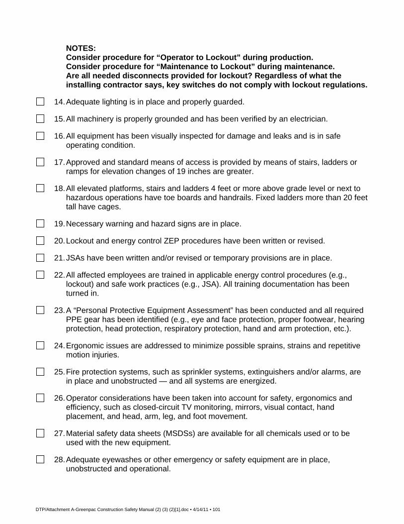
DTP/Attachment A-Greenpac Construction Safety Manual (2) (3) (2)[1].doc • 4/14/11 • 101
NOTES: Consider procedure for “Operator to Lockout” during production. Consider procedure for “Maintenance to Lockout” during maintenance. Are all needed disconnects provided for lockout? Regardless of what the installing contractor says, key switches do not comply with lockout regulations.
14. Adequate lighting is in place and properly guarded.
15. All machinery is properly grounded and has been verified by an electrician.
16. All equipment has been visually inspected for damage and leaks and is in safe operating condition.
17. Approved and standard means of access is provided by means of stairs, ladders or ramps for elevation changes of 19 inches are greater.
18. All elevated platforms, stairs and ladders 4 feet or more above grade level or next to hazardous operations have toe boards and handrails. Fixed ladders more than 20 feet tall have cages.
19. Necessary warning and hazard signs are in place.
20. Lockout and energy control ZEP procedures have been written or revised.
21. JSAs have been written and/or revised or temporary provisions are in place.
22. All affected employees are trained in applicable energy control procedures (e.g., lockout) and safe work practices (e.g., JSA). All training documentation has been turned in.
23. A “Personal Protective Equipment Assessment” has been conducted and all required PPE gear has been identified (e.g., eye and face protection, proper footwear, hearing protection, head protection, respiratory protection, hand and arm protection, etc.).
24. Ergonomic issues are addressed to minimize possible sprains, strains and repetitive motion injuries.
25. Fire protection systems, such as sprinkler systems, extinguishers and/or alarms, are in place and unobstructed — and all systems are energized.
26. Operator considerations have been taken into account for safety, ergonomics and efficiency, such as closed-circuit TV monitoring, mirrors, visual contact, hand placement, and head, arm, leg, and foot movement.
27. Material safety data sheets (MSDSs) are available for all chemicals used or to be used with the new equipment.
28. Adequate eyewashes or other emergency or safety equipment are in place, unobstructed and operational.

DTP/Attachment A-Greenpac Construction Safety Manual (2) (3) (2)[1].doc • 4/14/11 • 102
All hazards identified by the start-up inspection team shall be listed and attached to the checklist report, and all recognized hazards shall be addressed prior to start-up. Project Team Leader Signature: Date:
Comments:

DTP/Attachment A-Greenpac Construction Safety Manual (2) (3) (2)[1].doc • 4/14/11 • 103
Greenpac Earthquake Preparedness Process Process Please see the following table for stages in this process. Prior to the earthquake
Stage
Description Who
1 Secure filing cabinets, bookshelves, hot water heaters, and other free-standing equipment.
2 Ensure shelves have a vertical border on the front edge to prevent materials from falling off.
3 Store enough food and equipment to sustain all employees for 72 hours. This list should include at least the following (or an equivalent version): Canned meats, vegetables and fruits that can be eaten
without heating Energy bars, bottled/canned fruit juices and
crackers/cookies Bottled water, coffee, tea Manual can opener, small pan to boil water and
cooking/eating utensils Portable radio and flashlights with batteries Blankets Personal hygiene items (toilet paper, toothpaste, etc.) Small Sterno stove (or equivalent) and fuel First-aid kit and fire extinguishers Small camera and film/batteries (or disk for digital
camera) to facilitate documentation of any damage that may occur
Encourage all on prescription medication to keep a current supply of their medicines on site
4 Provide brief instructions about what to do during and immediately after an earthquake (see next two sections) in a regular crew or department safety meeting.
5 Hold a practice drill five minutes before lunch to give personnel a feel for the process. Holding it just before lunch causes minimal production interruption.
6 Select a company location outside your immediate operating area to use as a telephone contact point. It is often easier to contact an out-of-state number than a local one. This second facility can be used as a contact point for corporate and others. As an example, Tukwila operations might select one of the Montana or Alaska locations as their point of contact.
During an earthquake

DTP/Attachment A-Greenpac Construction Safety Manual (2) (3) (2)[1].doc • 4/14/11 • 104
Stage
Description Who
1 DO NOT PANIC. Most earthquakes are not severe. 2 If you are indoors, remain indoors. Do not go outside unless
fire or building damage forces you to do so.
3 Take cover under a table, desk, workbench, or other object that will offer protection from flying glass and falling objects. Stay away from windows, outside doors, bookshelves, mobile tool chests, etc. If substantial cover is not available, cover your head with a coat, blanket or newspapers to shield against flying glass or debris.
4 DO NOT USE OPEN FLAMES of any kind and extinguish all smoking materials. Disconnect electrical equipment if there is no danger in doing so. Shut off operating equipment if this can be done safely.
5 If you are outdoors, stay outdoors and move away from structures that could fall, including buildings and overhead power lines. Because of the danger of falling debris is greatest near doorways and outer walls, do not attempt to enter a building immediately after a quake.
6 Give fallen electrical lines a wide berth. DO NOT CONTACT such lines and always assume that they are energized and very dangerous.
7 If you are driving when an earthquake occurs, stop as quickly as safety permits in the best available space away from buildings, overhead power lines, trees, or cliffs where material may fall on your vehicle. Don’t park on a bridge or overpass because they are more likely to fail. STAY in the vehicle; it is usually a safe haven from debris and will insulate you from any fallen power lines.
After the earthquake
Stage
Description Who
1 Remain calm and expect potential aftershocks. 2 Perform a headcount; perform a search for any that are
missing.
3 Provide first-aid for any that are injured. Summon paramedics (9-1-1) or the appropriate emergency response number only for those who are severely injured and need additional assistance. Emergency agencies are going to be busy, so they should be called only when necessary. Be sure those on medication are taking their medicine as necessary.
4 Use caution if you must enter a building. Stay away from severely damaged structures.

DTP/Attachment A-Greenpac Construction Safety Manual (2) (3) (2)[1].doc • 4/14/11 • 105
5 Check for damaged utilities, especially gas leaks and downed power lines. Shut off gas and water sources, if possible. Extinguish any fires if you can do so safely. Summon the fire department for those that you cannot control.
6 Use telephones sparingly. Telephone systems (landlines and cellular telephones) will be burdened with traffic.
7 Begin to survey the damage WITHOUT exposing personnel to unsafe conditions. Make personnel as comfortable as possible if they must stay at a damaged facility and are unable to carry on operations as usual.
8 Take photos of any damage before beginning cleanup and repair operations.
9 When safe to do so and after the damage has been documented, begin salvage operations. IF there is structural damage, the building must be inspected by a licensed structural engineer prior to re-entry.
10 Report the damage to the corporate office when conditions allow.

DTP/Attachment A-Greenpac Construction Safety Manual (2) (3) (2)[1].doc • 4/14/11 • 106
Bomb Threat by Phone Checklist
Remain clam. Do not antagonize the caller. Time Call Received Time Ended
Exact Words of Caller (ask caller to repeat)
Time Bomb is Set to Explode Where Located Building: Floor/Area:
What Kind of Bomb?
Description of Bomb
Reason for Bombing (remind caller that innocent people could be killed or injured)
Demands (if any)
Information about Caller Sex Age Speech (accent, impediment)
Any Mannerisms (calm, nervous, frightened, threatening)
Recognize Voice?
Background Noise (type)
What Line Did Call Come In On?
Additional Information
Notify

DTP/Attachment A-Greenpac Construction Safety Manual (2) (3) (2)[1].doc • 4/14/11 • 107
Greenpac This document must be signed and returned to the Safety or Purchasing Department before any work commences.
I HAVE RECEIVED AND READ A COPY OF THE GREENPAC CONSTRUCTION
SAFETY POLICIES AND PROCEDURES. I UNDERSTAND AND AGREE TO
COMPLY WITH THESE POLICIES AND ALL FEDERAL, STATE AND LOCAL
GOVERNMENT SAFETY REGULATIONS. ________________________________ COMPANY NAME ________________________________ AUTHORIZED SIGNATURE ________________________________ DATE

Attachment B Job Hazard Analyses

North America Job Hazard Analysis ERM Actions During Subsurface Clearance and Drilling
Project Name: Former No.2 Mill facility Project Number: 0128439 Job / Task Name: Excavation of soil JHA No.: 6
ERM North America 1 Form Rev.: 05-08
Document Routing FSO Project Manager
Retain copy in site health & safety file, amend to HASP as necessary. Retain copy in the office health & safety file, amend to HASP as necessary.
Instructions: This JHA has been developed and approved by the North America Safety Team. Prior to conducting fieldwork.
site-specific hazards related to this task must be incorporated by the project team. Once completed, the JHA should be reviewed regularly with site personnel who will be performing this task.
Task Description: General guidelines for working safely when performing any ground penetrating activities (excluding surface soil sampling) and ERM personnel activities during overseeing drilling. Hazard Analysis:
Task Step Hazard Control Measures Identify a Client Contact Person
Client contacts that are not familiar with the site layout could cause critical information to be missed during safety planning.
Determine degree of knowledge of our client contact by evaluating their current job duties at the site, length of time they have worked at the site, and time in their current job. If the ERM team does not feel comfortable with the level of experience of our client contact, take additional measures to ensure all pertinent subsurface utilities and services information is gathered.
Engage Subcontractors Subcontractors who have not been evaluated against ERM minimum safety standards or who do not meet minimum safety standards may pose more risk.
Use only ERM subcontractors who are identified as having met our minimum safety standards. In cases where using an already-qualified subcontractor is not possible, ensure extra precautions are taken to provide safety oversight to the work.
Appoint an ERM Subsurface Clearance “Experienced Person” to the project
ERM employees who are not experienced with SSC issues may not recognize critical zones or clues to other site utilities/services.
Ensure a “SSC Experienced Person” is assigned to the project to provide oversight of ground penetrations and to mentor less experienced ERM employees.

North America Job Hazard Analysis ERM Actions During Subsurface Clearance and Drilling
Project Name: Former No.2 Mill facility Project Number: 0128439 Job / Task Name: Excavation of soil JHA No.: 6
ERM North America 2 Form Rev.: 05-08
Task Step Hazard Control Measures Gather site-specific subsurface information
Incomplete or inaccurate site utility/service drawings may lead the ERM project team to incorrect conclusions regarding what utilities/services are onsite.
Obtain the most recent “as-built” drawings and additional site information such as easements, rights-of-way, historical plot plans, etc. to assist making decisions about other actions that will be required at the site.
Develop the HASP Using incorrect documents in safety planning may lead to not considering all pertinent information.
A Level 2 WARN HASP for Intrusive Work (minimum) must be used when performing any ground penetrations, with the exception of surface soil sampling. The Level 2 HASP contains a “Site Services Model” that ERM uses to evaluate SSC hazards.
Develop the Site Services Model
Critical zones and a whole-site view of utilities and services at the site are more difficult to do if not put into the Site Services Model.
Use the Site Services Model to identify gaps in knowledge from all drawings and other verbal information from our client contact. Identify locations of key isolation and shutoffs closest to the work area for each type of utility/service.
Make Preliminary Determinations
Not recognizing or identifying critical zones poses great hazard to ERM employees in the field from contact with electricity or other utilities.
Establish critical zones and excavation buffers (if needed) for the work. Initial critical zone determinations may change in the field but are a good starting point in hazard identification.
Identify Preliminary Ground Disturbance Locations
Planning ground disturbance locations inside critical zones poses great hazard to ERM employees in the field from contact with electricity or other utilities.
Ensure critical zones have been identified using the Site Services Model and then identify locations outside those critical zones up-front, if possible. If a ground disturbance inside a critical zone is absolutely necessary, notify the site PIC and obtain guidance from him/her before proceeding.
Public and/or Private Utility Markout
Not having utilities marked may lead to a subsurface clearance strike.
Contact public and private utility markout services giving them enough time to respond. A minimum of 24-hour notification to utility locators is required in most states, and may vary higher in some states.
Conduct the Site Walk Inexperienced people conducting the site walk may miss pertinent information regarding utilities and/or services.
The “SSC Experienced Person” must lead the site walk and should be accompanied by our client contact. Each ground disturbance location should be approved by our client contact (written approval preferred, verbal approval acceptable).

North America Job Hazard Analysis ERM Actions During Subsurface Clearance and Drilling
Project Name: Former No.2 Mill facility Project Number: 0128439 Job / Task Name: Excavation of soil JHA No.: 6
ERM North America 3 Form Rev.: 05-08
Task Step Hazard Control Measures Inspect Each Ground Disturbance Location
Inexperienced people conducting inspection may miss pertinent information regarding utilities and/or services.
The “SSC Experienced Person” must lead inspection of each Ground Disturbance Location. Any visual clues of subsurface obstruction/utilities should be documented. Critical zones may have to be reassessed at this point. Use the SSC Checklist to document this inspection for each point inside a critical zone, at a minimum.
Finalize Critical Zone Determinations
Not performing this verification step in the field may lead to a SSC strike.
Use information gathered during pre-planning, utility markout, and site walk/inspection to verify critical zones that have been previously established. Revise critical zones as necessary. Use the SSC Checklist to document points inside critical zones. If points are confirmed inside critical zones, either step out and relocate the ground disturbance location, or contact the PIC for additional guidance.
Oversee setup of drilling equipment
Overhead electrical/other lines may come in contact with drill rigs. Materials stored in the vicinity of drill rigs may pose various hazards to employees.
Ensure drill rigs are set up in areas where they will not contact overhead lines when being positioned. The minimum distance for drill rig clearance is 25 feet unless special permission is granted by the utility company. When a drill rig must be maneuvered in tight quarters, the presence of a second person is required to ensure adequate clearance. If backing-up is required, two ground guides will be used: one in the direction the rig is moving and the other in the operator’s normal field of vision. Move tools, materials, cords, hoses, and debris to prevent trip hazards and contact with moving drill rig parts. Secure tools and equipment subject to displacement or falling. Store any flammable materials away from ignition sources and in approved containers.
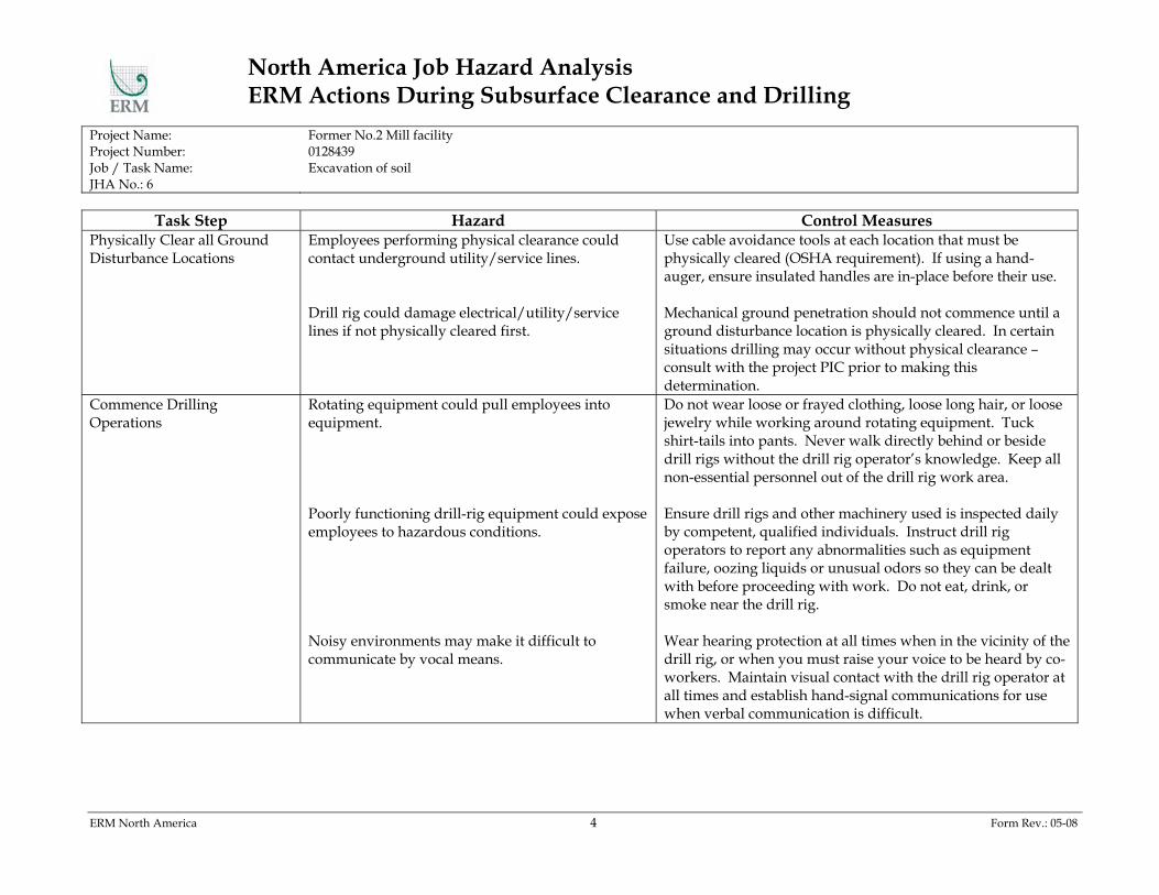
North America Job Hazard Analysis ERM Actions During Subsurface Clearance and Drilling
Project Name: Former No.2 Mill facility Project Number: 0128439 Job / Task Name: Excavation of soil JHA No.: 6
ERM North America 4 Form Rev.: 05-08
Task Step Hazard Control Measures Physically Clear all Ground Disturbance Locations
Employees performing physical clearance could contact underground utility/service lines. Drill rig could damage electrical/utility/service lines if not physically cleared first.
Use cable avoidance tools at each location that must be physically cleared (OSHA requirement). If using a hand-auger, ensure insulated handles are in-place before their use. Mechanical ground penetration should not commence until a ground disturbance location is physically cleared. In certain situations drilling may occur without physical clearance – consult with the project PIC prior to making this determination.
Commence Drilling Operations
Rotating equipment could pull employees into equipment. Poorly functioning drill-rig equipment could expose employees to hazardous conditions. Noisy environments may make it difficult to communicate by vocal means.
Do not wear loose or frayed clothing, loose long hair, or loose jewelry while working around rotating equipment. Tuck shirt-tails into pants. Never walk directly behind or beside drill rigs without the drill rig operator’s knowledge. Keep all non-essential personnel out of the drill rig work area. Ensure drill rigs and other machinery used is inspected daily by competent, qualified individuals. Instruct drill rig operators to report any abnormalities such as equipment failure, oozing liquids or unusual odors so they can be dealt with before proceeding with work. Do not eat, drink, or smoke near the drill rig. Wear hearing protection at all times when in the vicinity of the drill rig, or when you must raise your voice to be heard by co-workers. Maintain visual contact with the drill rig operator at all times and establish hand-signal communications for use when verbal communication is difficult.

North America Job Hazard Analysis ERM Actions During Subsurface Clearance and Drilling
Project Name: Former No.2 Mill facility Project Number: 0128439 Job / Task Name: Excavation of soil JHA No.: 6
ERM North America 5 Form Rev.: 05-08
Task Step Hazard Control Measures Complete Drilling Operations Equipment allowed to remain running poses pinch-
point and potential explosion hazards to employees. Shut down drill rigs before repairing or lubricating parts (except those that must be in motion for lubrication). Shut down mechanical equipment prior to and during fueling operations. When refueling or transferring fuel, containers and equipment must be bonded to prevent the buildup of static electricity.
Personal Protective Equipment Required for this Task:
Type Description Insulated hand-augers Hand-augers fitted with rubber handles, or other non-conductive material. Training Required for this Task:
Type Description SSC Classroom Training SSC Experienced Person
Initial classroom training detailing the ERM subsurface clearance process, tools, and forms. At least one must be present on all sites involving SSC. The Experienced Person will both give SSC expertise in project execution and mentor less experienced employees.
Forms Associated with this Task:
Type Description SSC Checklist SSC Mentorship Card Daily Drill Rig Inspection Form
Checklist detailing the ERM SSC process, and providing tools to ensure critical zones and excavation buffers are properly identified and validated in the field. The SSC Mentorship Card provides Experienced Persons with topics to be covered with less experienced employees on SSC sites, and also documents mentoring of the less experienced employees. Form required to be used by ERM subcontractors to document daily inspection of drill rigs. This form should be provided by the drill rig operating company. Completed forms should be kept with the

North America Job Hazard Analysis ERM Actions During Subsurface Clearance and Drilling
Project Name: Former No.2 Mill facility Project Number: 0128439 Job / Task Name: Excavation of soil JHA No.: 6
ERM North America 6 Form Rev.: 05-08
HASP and filed in project files.
Site-Specific Job Hazard Analysis Completed by:
Name Date

North America Job Hazard Analysis ERM Actions During Subsurface Clearance and Excavations
Project Name: Former No. 2 Mill Facility Project Number: 0128439 Job / Task Name: Soil Excavation JHA No.: 7
ERM North America 1 Form Rev.: 05-08
Document Routing FSO Project Manager
Retain copy in site health & safety file, amend to HASP as necessary. Retain copy in the office health & safety file, amend to HASP as necessary.
Instructions: This JHA has been developed and approved by the North America Safety Team. Prior to conducting fieldwork.
site-specific hazards related to this task must be incorporated by the project team. Once completed, the JHA should be reviewed regularly with site personnel who will be performing this task.
Task Description: General guidelines for working safely when performing any ground penetrating activities (excluding surface soil sampling) and ERM personnel activities during overseeing excavations. Hazard Analysis:
Task Step Hazard Control Measures Identify a Client Contact Person
Client contacts that are not familiar with the site layout could cause critical information to be missed during safety planning.
Determine degree of knowledge of our client contact by evaluating their current job duties at the site, length of time they have worked at the site, and time in their current job. If the ERM team does not feel comfortable with the level of experience of our client contact, take additional measures to ensure all pertinent subsurface utilities and services information is gathered.
Engage Subcontractors Subcontractors who have not been evaluated against ERM minimum safety standards or who do not meet minimum safety standards may pose more risk.
Use only ERM subcontractors who are identified as having met our minimum safety standards. In cases where using an already-qualified subcontractor is not possible, ensure extra precautions are taken to provide safety oversight to the work.
Appoint an ERM Subsurface Clearance “Experienced Person” to the project
ERM employees who are not experienced with SSC issues may not recognize critical zones or clues to other site utilities/services.
Ensure a “SSC Experienced Person” is assigned to the project to provide oversight of ground penetrations and to mentor less experienced ERM employees.

North America Job Hazard Analysis ERM Actions During Subsurface Clearance and Excavations
Project Name: Former No. 2 Mill Facility Project Number: 0128439 Job / Task Name: Soil Excavation JHA No.: 7
ERM North America 2 Form Rev.: 05-08
Task Step Hazard Control Measures Gather site-specific subsurface information
Incomplete or inaccurate site utility/service drawings may lead the ERM project team to incorrect conclusions regarding what utilities/services are onsite.
Obtain the most recent “as-built” drawings and additional site information such as easements, rights-of-way, historical plot plans, etc. to assist making decisions about other actions that will be required at the site.
Develop the HASP Using incorrect documents in safety planning may lead to not considering all pertinent information.
A Level 2 WARN HASP for Intrusive Work (minimum) must be used when performing any ground penetrations, with the exception of surface soil sampling. The Level 2 HASP contains a “Site Services Model” that ERM uses to evaluate SSC hazards.
Develop the Site Services Model
Critical zones and a whole-site view of utilities and services at the site are more difficult to do if not put into the Site Services Model.
Use the Site Services Model to identify gaps in knowledge from all drawings and other verbal information from our client contact. Identify locations of key isolation and shutoffs closest to the work area for each type of utility/service.
Make Preliminary Determinations
Not recognizing or identifying critical zones poses great hazard to ERM employees in the field from contact with electricity or other utilities.
Establish critical zones and excavation buffers for the work. Initial critical zone determinations may change in the field but are a good starting point in hazard identification.
Identify Preliminary Ground Disturbance Locations
Planning ground disturbance locations inside critical zones poses great hazard to ERM employees in the field from contact with electricity or other utilities.
Ensure excavation buffers have been identified using the Site Services Model and then identify locations outside those critical zones up-front, if possible. If a ground disturbance inside a critical zone is absolutely necessary, notify the site PIC and obtain guidance from him/her before proceeding.
Public and/or Private Utility Markout
Not having utilities marked may lead to a subsurface clearance strike.
Contact public and private utility markout services giving them enough time to respond. A minimum of 24-hour notification to utility locators is required in most states, and may vary higher in some states.
Conduct the Site Walk Inexperienced people conducting the site walk may miss pertinent information regarding utilities and/or services.
The “SSC Experienced Person” must lead the site walk and should be accompanied by our client contact. Each ground disturbance location should be approved by our client contact (written approval preferred, verbal approval acceptable).

North America Job Hazard Analysis ERM Actions During Subsurface Clearance and Excavations
Project Name: Former No. 2 Mill Facility Project Number: 0128439 Job / Task Name: Soil Excavation JHA No.: 7
ERM North America 3 Form Rev.: 05-08
Task Step Hazard Control Measures Inspect Each Ground Disturbance Location
Inexperienced people conducting inspection may miss pertinent information regarding utilities and/or services.
The “SSC Experienced Person” must lead inspection of each Ground Disturbance Location. Any visual clues of subsurface obstruction/utilities should be documented. Critical zones may have to be reassessed at this point. Use the SSC Checklist to document this inspection for each point inside a critical zone, at a minimum.
Finalize Critical Zone Determinations
Not performing this verification step in the field may lead to a SSC strike.
Use information gathered during pre-planning, utility markout, and site walk/inspection to verify critical zones that have been previously established. Revise critical zones as necessary. Use the SSC Checklist to document points inside critical zones. If points are confirmed inside critical zones, either step out and relocate the ground disturbance location, or contact the PIC for additional guidance.
Establish Excavation Buffers Mechanical digging near subsurface structures not already designated for removal can expose employees to electrical or other serious hazards.
For at least 2 feet in all directions from an identified subsurface structure, use non-conductive tools and physically remove soil.
Notify Equipment Operators where Excavation Buffers are Located
Mechanical digging near subsurface structures not already designated for removal can expose employees to electrical or other serious hazards.
If physically clearing is performed, use cable avoidance tools at each location that must be physically cleared (OSHA requirement). If using a hand-auger, ensure insulated handles are in-place before their use. DO NOT DIG INSIDE AN EXCAVATION BUFFER WITH MECHANICAL EQUIPMENT.
Personal Protective Equipment Required for this Task:
Type Description Insulated hand-augers Hand-augers fitted with rubber handles, or other non-conductive material.
North America Job Hazard Analysis ERM Actions During Subsurface Clearance and Excavations
Project Name: Former No. 2 Mill Facility Project Number: 0128439 Job / Task Name: Soil Excavation JHA No.: 7
ERM North America 4 Form Rev.: 05-08
Training Required for this Task: Type Description
SSC Classroom Training SSC Experienced Person
Initial classroom training detailing the ERM subsurface clearance process, tools, and forms. At least one must be present on all sites involving SSC. The Experienced Person will both give SSC expertise in project execution and mentor less experienced employees.
Forms Associated with this Task:
Type Description SSC Checklist SSC Mentorship Card Daily Excavation Inspection Form
Checklist detailing the ERM SSC process, and providing tools to ensure critical zones and excavation buffers are properly identified and validated in the field. The SSC Mentorship Card provides Experienced Persons with topics to be covered with less experienced employees on SSC sites, and also documents mentoring of the less experienced employees. Form required to be used by ERM subcontractors to document daily inspection of excavations. Completed forms should be kept with the HASP and filed in project files.
Site-Specific Job Hazard Analysis Completed by:
Name Date

North America Job Hazard Analysis Work in High Noise Environments
Project Name: Former No. Mill Facility Project Number: 0128439 Job / Task Name: Soil Excavation JHA No.: 8
ERM North America 1 Form Rev.: 05-08
Document Routing FSO Project Manager
Retain copy in site health & safety file, amend to HASP as necessary. Retain copy in the office health & safety file, amend to HASP as necessary.
Instructions: This JHA has been developed and approved by the North America Safety Team. Prior to conducting fieldwork.
site-specific hazards related to this task must be incorporated by the project team. Once completed, the JHA should be reviewed regularly with site personnel who will be performing this task.
Task Description: Guidelines for safe work in any environment with elevated noise levels. Hazard Analysis:
Task Step Hazard Control Measures Prepare for Work Not having hearing protection or noise monitoring
equipment could expose employees to unknown levels of elevated noise.
For work environments known or suspected to present elevated noise hazards, ensure hearing protection is procured and available at the jobsite. For any employee working on the site who has not attended hearing conservation training within the past year, review this JHA with them and document their training. Determine whether noise monitoring has been done on other projects with similar scopes of work by contacting your Safety Team representative. If work on the project will last 30 days or more, procure a noise dosimeter and perform personnel monitoring at the site to document noise levels.
Conduct the Work Damage to hearing from sustained elevated noise or intermittent impact noise.
If noise dosimetry is not being conducted at the project, use the following rule of thumb to determine whether hearing protection is required: If you are standing within 3 feet of another person and have to raise your voice to be understood by them when talking, hearing protection must be worn.

North America Job Hazard Analysis Work in High Noise Environments
Project Name: Former No. Mill Facility Project Number: 0128439 Job / Task Name: Soil Excavation JHA No.: 8
ERM North America 2 Form Rev.: 05-08
Task Step Hazard Control Measures Report Dosimetry Monitoring Results
Lack of consolidated noise dosimetry monitoring results can result in other employees on different projects not being aware of typical noise levels.
OSHA allows noise dosimetry monitoring results collected when working with specific equipment to be used on any other project site where the same equipment is in-use. Report dosimetry monitoring results to your Safety Team representative so they can be included in a North America-wide listing of typical noise levels.
Personal Protective Equipment Required for this Task:
Type Description Hearing Protection Training Required for this Task:
Type Description Hearing Conservation Forms Associated with this Task:
Type Description None
Site-Specific Job Hazard Analysis Completed by:
Name Date

North America Job Hazard Analysis Engaging and Managing Subcontractors
Project Name: Former No. 2 Mill Facility Project Number: 0128439 Job / Task Name: Soil Excavation JHA No.: 9
ERM North America 1 Form Rev.: 05-08
Document Routing FSO Project Manager
Retain copy in site health & safety file, amend to HASP as necessary. Retain copy in the office health & safety file, amend to HASP as necessary.
Instructions: This JHA has been developed and approved by the North America Safety Team. Prior to conducting fieldwork.
site-specific hazards related to this task must be incorporated by the project team. Once completed, the JHA should be reviewed regularly with site personnel who will be performing this task.
Task Description: Guidelines for managing safety of ERM-hired subcontractors to ensure they work safely and ERM liability is minimized. Hazard Analysis:
Task Step Hazard Control Measures Choose Subcontractor to Perform Work
Lack of executed contractual documentation may increase ERM liability. Insurance documents collected during the safety prequalification process may not be sufficient to meet specific client contractual requirements. Selecting subcontractors that do not meet ERM minimum safety criteria can result in poor safety performance on ERM projects.
The project PIC and/or PM must ensure a signed, executed contract is in-place prior to subcontractors performing work on the jobsite for ERM. The project PIC and/or PM must ensure that insurance certificates on-file for subcontractors meet or exceed contractual insurance requirements mandated by ERM clients. If the insurance certificate on-file is out-of-date or does not represent sufficient coverage, the project PIC and/or PM must obtain an updated insurance certificate from the subcontractor prior to the subcontractor performing work on the jobsite for ERM. Consult the North America “Subcontractor Information” page and select a subcontractor that meets ERM minimum safety criteria. If selection of an already-prequalified subcontractor is not possible due to business considerations or client wishes, provide enhanced subcontractor oversight on the jobsite.

North America Job Hazard Analysis Engaging and Managing Subcontractors
Project Name: Former No. 2 Mill Facility Project Number: 0128439 Job / Task Name: Soil Excavation JHA No.: 9
ERM North America 2 Form Rev.: 05-08
Task Step Hazard Control Measures Prepare Site HASP Documents Not informing ERM-hired subcontractors of ERM
safety requirements for their work may expose employees to hazardous conditions and cause unnecessary project delays. Not obtaining authorized subcontractor signatures on ERM HASPs may expose ERM to additional liability. The lack of a specific scope of work for an ERM subcontractor opens the possibility of whether ERM or the subcontractor is responsible for certain aspects of jobsite work. Any ERM attempt to author safety documents for use during completion of tasks on jobsites by subcontractors may not be sufficient to fully control site safety hazards posed by subcontractor work.
The project PIC and/or PM must ensure the subcontractor has received a copy of the ERM HASP and supporting documentation prior to mobilization to the jobsite. The subcontractor must be made aware that their personnel must follow provisions in the ERM HASP at a minimum, but that they may not rely on ERM documents for their employee’s health and safety protection. Prior to any jobsite work proceeding, obtain the signature of an authorized representative for the subcontractor on the ERM HASP. Also, have the subcontractor’s authorized representative designate one of their employees, by name, to serve as the jobsite contact for ERM safety concerns. List the jobsite safety contact in the ERM HASP. Specify both the ERM and the subcontractor’s scope of work in the ERM HASP document. Ensure that any subcontractor personnel on-site has reviewed and signed the site HASP. In all cases, require the ERM subcontractor to either develop their own site-specific HASP, or develop Job Hazard Analyses (JHA) for the specific tasks they will perform. Attach these documents to the ERM HASP as appendices.

North America Job Hazard Analysis Engaging and Managing Subcontractors
Project Name: Former No. 2 Mill Facility Project Number: 0128439 Job / Task Name: Soil Excavation JHA No.: 9
ERM North America 3 Form Rev.: 05-08
Task Step Hazard Control Measures Conduct the Work On jobsites where ERM uses subcontracted services,
additional liability arising from the OSHA “Multi-Employer Worksite Rule” may be present.
Ensure subcontractor work is overseen by ERM personnel at all times. Whenever subcontractor personnel are present on a jobsite performing work, an ERM employee should be present and engaged in the work being performed. Always include subcontractor personnel in daily jobsite tailgate safety meetings and have them indicate their presence and understanding of the information presented by signing the ERM form documenting the meeting. ERM personnel at the jobsite should perform regular safety inspections of the site, including subcontractor activities. Any deficiencies noted during inspections should be forwarded to the subcontractor’s jobsite safety contact for resolution and report-back to ERM. For imminent danger situations (those that may cause loss of life or limb), the ERM inspector should stop the subcontractor’s work and ensure all on site retreat until the imminent danger hazard is abated. Do not supply subcontractor personnel with personal protective equipment (PPE). If PPE must be provided to subcontractors, ERM personnel must inspect the PPE and document the inspection prior to providing it to subcontractor personnel. If ERM is performing air monitoring for the subcontractor, ensure calibration of air monitoring equipment is done before and after each use. At a minimum, air monitoring equipment must be calibrated at least once per day. Document equipment calibration and file with the site HASP.

North America Job Hazard Analysis Engaging and Managing Subcontractors
Project Name: Former No. 2 Mill Facility Project Number: 0128439 Job / Task Name: Soil Excavation JHA No.: 9
ERM North America 4 Form Rev.: 05-08
Task Step Hazard Control Measures After Job Completion, Forward Comments to ERM North America Safety Team
Obtaining services from subcontractors who have met ERM minimum safety criteria but have performed poorly on jobsites poses risk to ERM employees on future jobsites.
Submit any comments about the subcontractor’s safety performance while working on the ERM jobsite to the ERM North America Safety Team. These comments will be stored in our database and provided to ERM PICs and/or PMs seeking quality subcontractors for future work.
Personal Protective Equipment Required for this Task:
Type Description None Training Required for this Task:
Type Description None Forms Associated with this Task:
Type Description Subcontractor Safety Prequalification Checklist Subcontractor Insurance Certificate
ERM form given to subcontractors that collects information necessary to determine whether the subcontractor meets ERM’s minimum safety criteria. Subcontractor-supplied form issued by the subcontractor’s insurance carrier or broker evidencing current insurance coverage.
Site-Specific Job Hazard Analysis Completed by:
Name Date

North America Job Hazard Analysis Engaging and Managing Subcontractors
Project Name: Former No. 2 Mill Facility Project Number: 0128439 Job / Task Name: Soil Excavation JHA No.: 9
ERM North America 5 Form Rev.: 05-08

North America Job Hazard Analysis Hazard Communication
Project Name: Former No. 2 Mill Facility Project Number: 0128439 Job / Task Name: Soil Excavation JHA No.: 10
ERM North America 1 Form Rev.: 05-08
Document Routing FSO Project Manager
Retain copy in site health & safety file, amend to HASP as necessary. Retain copy in the office health & safety file, amend to HASP as necessary.
Instructions: This JHA has been developed and approved by the North America Safety Team. Prior to conducting fieldwork.
site-specific hazards related to this task must be incorporated by the project team. Once completed, the JHA should be reviewed regularly with site personnel who will be performing this task.
Task Description: Guidelines for communicating hazards posed by the storage and/or use of chemicals. Hazard Analysis:
Task Step Hazard Control Measures Storing Chemicals in the Office Setting
Chemicals stored in ERM offices or Field Project Offices may lead to employee chemical exposure, chemical spills, or fires from flammable materials.
If at all possible, do not store chemicals in the office environment. For each chemical product used by ERM employees or stored in an ERM field or office location, a MSDS sheet must be obtained and kept on-file. A chemical inventory list must be prepared and updated as new or different chemicals are procured. Chemical containers must be labeled in accordance with OSHA regulations. Train all employees who will use or be present in the general vicinity of chemicals annually about hazard communication. If new or updated chemicals are procured, hazard communication training must be given to affected employees prior to using or storing the chemical.

North America Job Hazard Analysis Hazard Communication
Project Name: Former No. 2 Mill Facility Project Number: 0128439 Job / Task Name: Soil Excavation JHA No.: 10
ERM North America 2 Form Rev.: 05-08
Task Step Hazard Control Measures Using Chemicals Employees may be exposed to chemical hazards via
skin contact, ingestion, inhalation, or punctures in the skin.
Before using any chemical, make sure a jobsite WARN Health and Safety Plan (HASP) has been prepared and taken the chemical being used into account. Wear protective equipment as specified in the HASP. If chemicals are being used by subcontractors, ensure all employees on the jobsite have been told about the chemical in-use and are protected. If chemical exposure occurs, even if medical symptoms are not present, inform the Field Safety Office or Office H&S Contact.
Large Chemical Spills Large chemicals spills may expose employees to significant health hazards.
For large chemical spills (generally anything larger than 1 gallon in size), HAZWOPER training is required to perform any action other than retreating from the area and contacting appropriately-trained personnel to mitigate the spill. Do not attempt to stop or clean-up a spill without current HAZWOPER training, current medical clearance, current respirator training, and a current respirator fit-test.
Personal Protective Equipment Required for this Task:
Type Description None Training Required for this Task:
Type Description Hazard Communication An annually-required training discussing general chemical hazards, MSDS sheets, and how to respond
to general chemical emergency situations.

North America Job Hazard Analysis Hazard Communication
Project Name: Former No. 2 Mill Facility Project Number: 0128439 Job / Task Name: Soil Excavation JHA No.: 10
ERM North America 3 Form Rev.: 05-08
Forms Associated with this Task: Type Description
Material Safety Data Sheet (MSDS) International Chemical Safety Card
An informational document containing information about chemical composition, hazardous properties, and steps to take in emergency situations involving chemicals. A chemical-specific document developed by the National Institute of Occupational Safety and Health providing abbreviated information similar to a MSDS.
Site-Specific Job Hazard Analysis Completed by:
Name Date

North America Job Hazard Analysis Airborne Contaminants and Reproductive Hazards
Project Name: Former No. 2 Mill Facility Project Number: 0128439 Job / Task Name: Soil Excavation JHA No.: 11
ERM North America 1 Form Rev.: 05-08
Document Routing FSO Project Manager
Retain copy in site health & safety file, amend to HASP as necessary. Retain copy in the office health & safety file, amend to HASP as necessary.
Instructions: This JHA has been developed and approved by the North America Safety Team. Prior to conducting fieldwork.
site-specific hazards related to this task must be incorporated by the project team. Once completed, the JHA should be reviewed regularly with site personnel who will be performing this task.
Task Description: Description of specific chemical air contaminants requiring additional regulatory actions. Hazard Analysis:
Task Step Hazard Control Measures

North America Job Hazard Analysis Airborne Contaminants and Reproductive Hazards
Project Name: Former No. 2 Mill Facility Project Number: 0128439 Job / Task Name: Soil Excavation JHA No.: 11
ERM North America 2 Form Rev.: 05-08
Task Step Hazard Control Measures Exposure to specific OSHA-regulated chemical hazards during work
Certain chemicals have been found to present more significant long-term health hazards to employees when they are exposed to them, including sensitization, development of certain cancers, and others.
If the following chemicals are being used on a jobsite, and work will occur for more than 30 consecutive days, OSHA regulations generally require a plan to mitigate exposures, additional training, and medical monitoring in some cases.
13 carcinogens (see 29 CFR 1910. Asbestos Vinyl chloride Inorganic arsenic Lead Hexavalent chromium Cadmium Benzene Coke oven emissions 1,2-dibromo-3-chloropropane Acrylonitrile Ethylene oxide Formaldehyde Methylenedianiline 1,3-butadiene Methylene chloride
Exposure to reproductive chemical hazards during work
Certain chemicals have been found to affect the reproductive systems in males and females and require additional personnel protection if used.
Chemicals posing reproductive hazards will be specified in site-specific HASPs. Follow all provisions of the HASP to minimize or eliminate exposure to reproductive hazards.
Personal Protective Equipment Required for this Task:
Type Description Varies PPE varies depending on the specific chemical being used. Consult the HASP for jobsite-specific
guidance.

North America Job Hazard Analysis Airborne Contaminants and Reproductive Hazards
Project Name: Former No. 2 Mill Facility Project Number: 0128439 Job / Task Name: Soil Excavation JHA No.: 11
ERM North America 3 Form Rev.: 05-08
Training Required for this Task: Type Description
Varies Training that must be given to employees varies on the specific chemical being used. Consult the HASP for jobsite-specific guidance.
Forms Associated with this Task:
Type Description None
Site-Specific Job Hazard Analysis Completed by:
Name Date

North America Job Hazard Analysis Heavy Equipment Operations
Project Name: Former No. 2 Mill Facility Project Number: 0128439 Job / Task Name: Soil Excavation JHA No.: 19
ERM North America 1 Form Rev.: 05-08
Document Routing FSO Project Manager
Retain copy in site health & safety file, amend to HASP as necessary. Retain copy in the office health & safety file, amend to HASP as necessary.
Instructions: This JHA has been developed and approved by the North America Safety Team. Prior to conducting fieldwork.
site-specific hazards related to this task must be incorporated by the project team. Once completed, the JHA should be reviewed regularly with site personnel who will be performing this task.
Task Description: Guidelines for working around heavy equipment. Hazard Analysis:
Task Step Hazard Control Measures Offsite Preparation Untrained workers operating heavy equipment
pose potential life-threatening hazards to employees.
ERM policy and practice is that our employees do not operate heavy equipment except in unusual circumstances. If ERM personnel are to operate heavy equipment, this must be stated in the health and safety plan for the project. Only employees with training and/or demonstrated experience operating heavy equipment may do so. Subcontractor personnel operating heavy equipment must be trained and/or have demonstrated experience operating such equipment. ERM must be in possession of evidence of training and/or experience prior to Subcontractor personnel operating such equipment. All heavy equipment must meet applicable design standards (ANSI, etc.). A copy of the operating manual must be carried on all heavy equipment, including a load-rating chart and any special operating considerations.
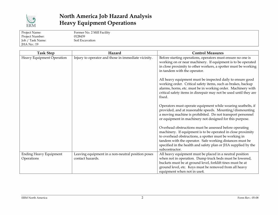
North America Job Hazard Analysis Heavy Equipment Operations
Project Name: Former No. 2 Mill Facility Project Number: 0128439 Job / Task Name: Soil Excavation JHA No.: 19
ERM North America 2 Form Rev.: 05-08
Task Step Hazard Control Measures Heavy Equipment Operation Injury to operator and those in immediate vicinity. Before starting operations, operators must ensure no one is
working on or near machinery. If equipment is to be operated in close proximity to other workers, a spotter must be working in tandem with the operator. All heavy equipment must be inspected daily to ensure good working order. Critical safety items, such as brakes, backup alarms, horns, etc. must be in working order. Machinery with critical safety items in disrepair may not be used until they are fixed. Operators must operate equipment while wearing seatbelts, if provided, and at reasonable speeds. Mounting/dismounting a moving machine is prohibited. Do not transport personnel or equipment in machinery not designed for this purpose. Overhead obstructions must be assessed before operating machinery. If equipment is to be operated in close proximity to overhead obstructions, a spotter must be working in tandem with the operator. Safe working distances must be specified in the health and safety plan or JHA supplied by the subcontractor.
Ending Heavy Equipment Operations
Leaving equipment in a non-neutral position poses contact hazards.
All heavy equipment must be placed in a neutral position when not in operation. Dump truck beds must be lowered, buckets must be at ground level, forklift tines must be at ground level, etc. Keys must be removed from all heavy equipment when not in use4.

North America Job Hazard Analysis Heavy Equipment Operations
Project Name: Former No. 2 Mill Facility Project Number: 0128439 Job / Task Name: Soil Excavation JHA No.: 19
ERM North America 3 Form Rev.: 05-08
Personal Protective Equipment Required for this Task: Type Description
High-visibility safety vest Vest worn by equipment operators and those working in the area impacted by moving machinery Training Required for this Task:
Type Description Heavy Equipment Operation Operators must be trained and/or have demonstrated experience for each type of heavy equipment
they will operate. Forms Associated with this Task:
Type Description Heavy Equipment Inspection form
Form for documenting daily heavy equipment inspections
Site-Specific Job Hazard Analysis Completed by:
Name Date

North America Job Hazard Analysis Energized Equipment and Lockout-Tagout
Project Name: Former No. Mill Facility Project Number: 0128439 Job / Task Name: Soil Excavation JHA No.: 22
ERM North America 1 Form Rev.: 05-08
Document Routing FSO Project Manager
Retain copy in site health & safety file, amend to HASP as necessary. Retain copy in the office health & safety file, amend to HASP as necessary.
Instructions: This JHA has been developed and approved by the North America Safety Team. Prior to conducting fieldwork.
site-specific hazards related to this task must be incorporated by the project team. Once completed, the JHA should be reviewed regularly with site personnel who will be performing this task.
Task Description: Guidelines for working on or around electrically energized equipment. Hazard Analysis:
Task Step Hazard Control Measures Offsite Preparation Locks, tags, and trained personnel may not be
present at the jobsite when needed. The health and safety plan for projects involving work on or oversight of work on electrical equipment must include provisions for lockout. Locks and tags must be on-hand at the at the location where lockout is being pertformed. Personnel performing lockout operations must have received documented lockout training. Staff these projects with personnel who have attended this training. Collect training certificates from subcontractors who will perform this work.

North America Job Hazard Analysis Energized Equipment and Lockout-Tagout
Project Name: Former No. Mill Facility Project Number: 0128439 Job / Task Name: Soil Excavation JHA No.: 22
ERM North America 2 Form Rev.: 05-08
Task Step Hazard Control Measures Work on Energized Equipment Electrocution may occur if lockout is not performed
correctly. Before working on electrically-energized equipment, it should be brought to a “zero-energy state”. This may involve turning the equipment’s power source off, or turning specific electrical breakers to the off position. “Zero-energy” is not attained until the individual working on the machinery attempts to turn the machine on and is unsuccessful. The individual(s) performing lockout-tagout must inform other personnel in the area that work on equipment is about to occur, and to not attempt to turn equipment on for any reason. Locks AND tags must be placed on equipment power sources by each individual performing work on the equipment using personally-identifiable locks. Tags must read “DANGER – DO NOT OPERATE” and be resistant to wear and tear by the environment they are being used in. In certain situations, the use of locks may not be possible (machinery must be kept energized to perform required work). In these cases the Project Manager and Field Safety Officer must be directly involved when tagout is taking place.
Remove locks and tags Removing locks and/or tags prematurely may lead to electrocution.
Do not allow anyone other than the individual who placed a lock/tag in-place to remove it. If the individual who placed the lock/tag is not immediately available to remove it, work must be suspended until he/she becomes available. If the individual who placed the lock/tag has left the jobsite, use the contact information located in the health and safety plan to attempt to contact them. If they are unable to be contacted, their lock/tag may only be removed through a joint decision from the PM, FSO, and Subcontractor supervisor.

North America Job Hazard Analysis Energized Equipment and Lockout-Tagout
Project Name: Former No. Mill Facility Project Number: 0128439 Job / Task Name: Soil Excavation JHA No.: 22
ERM North America 3 Form Rev.: 05-08
Task Step Hazard Control Measures Lockout Tagout Process Inspection on Sites Longer than 1 Year
Changes to electrically-energized equipment may cause lockout procedures to become obsolete.
For all sites where work extends beyond 1 year, a lockout process inspection must occur. The inspection will verify, for each piece of electrically-energized equipment normally worked on, that lockout procedures in-place are still valid. These process inspections must be documented.
Personal Protective Equipment Required for this Task:
Type Description None Training Required for this Task:
Type Description Lockout Lockout training describes the process of de-energizing electrical equipment prior to performing work
or maintenance on the equipment, and the safeguards that must be used to ensure electrical hazards to employees are controlled.
Forms Associated with this Task:
Type Description None
Site-Specific Job Hazard Analysis Completed by:
Name Date

North America Job Hazard Analysis Hazardous Waste Operations and Emergency Response
Project Name: Former No. 2 Mill facility Project Number: 0128439 Job / Task Name: Soil Excavation JHA No.: 27
ERM North America 1 Form Rev.: 05-08
Document Routing FSO Project Manager
Retain copy in site health & safety file, amend to HASP as necessary. Retain copy in the office health & safety file, amend to HASP as necessary.
Instructions: This JHA has been developed and approved by the North America Safety Team. Prior to conducting fieldwork.
site-specific hazards related to this task must be incorporated by the project team. Once completed, the JHA should be reviewed regularly with site personnel who will be performing this task.
Task Description: Guidelines for working on jobsites requiring compliance with the OSHA Hazardous Waste Operations and Emergency Response (HAZWOPER) standard. Hazard Analysis:
Task Step Hazard Control Measures Personal Protective Equipment Required for this Task:
Type Description Training Required for this Task:
Type Description None Forms Associated with this Task:

North America Job Hazard Analysis Hazardous Waste Operations and Emergency Response
Project Name: Former No. 2 Mill facility Project Number: 0128439 Job / Task Name: Soil Excavation JHA No.: 27
ERM North America 2 Form Rev.: 05-08
Type Description None
Site-Specific Job Hazard Analysis Completed by:
Name Date
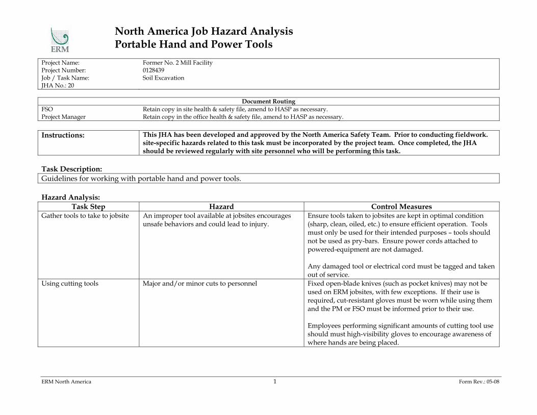
North America Job Hazard Analysis Portable Hand and Power Tools
Project Name: Former No. 2 Mill Facility Project Number: 0128439 Job / Task Name: Soil Excavation JHA No.: 20
ERM North America 1 Form Rev.: 05-08
Document Routing FSO Project Manager
Retain copy in site health & safety file, amend to HASP as necessary. Retain copy in the office health & safety file, amend to HASP as necessary.
Instructions: This JHA has been developed and approved by the North America Safety Team. Prior to conducting fieldwork.
site-specific hazards related to this task must be incorporated by the project team. Once completed, the JHA should be reviewed regularly with site personnel who will be performing this task.
Task Description: Guidelines for working with portable hand and power tools. Hazard Analysis:
Task Step Hazard Control Measures Gather tools to take to jobsite An improper tool available at jobsites encourages
unsafe behaviors and could lead to injury. Ensure tools taken to jobsites are kept in optimal condition (sharp, clean, oiled, etc.) to ensure efficient operation. Tools must only be used for their intended purposes – tools should not be used as pry-bars. Ensure power cords attached to powered-equipment are not damaged. Any damaged tool or electrical cord must be tagged and taken out of service.
Using cutting tools Major and/or minor cuts to personnel Fixed open-blade knives (such as pocket knives) may not be used on ERM jobsites, with few exceptions. If their use is required, cut-resistant gloves must be worn while using them and the PM or FSO must be informed prior to their use. Employees performing significant amounts of cutting tool use should must high-visibility gloves to encourage awareness of where hands are being placed.

North America Job Hazard Analysis Portable Hand and Power Tools
Project Name: Former No. 2 Mill Facility Project Number: 0128439 Job / Task Name: Soil Excavation JHA No.: 20
ERM North America 2 Form Rev.: 05-08
Task Step Hazard Control Measures Using screwdrivers Puncture injuries Do not hold objects in the palm of your hand and press a
screwdriver into it – these objects should be placed on a flat surface. Do not use screwdrivers as hammers, or use screwdrivers with broken handles. Use insulated screwdrivers for work on electrical equipment.
Using hammers Creation of sparks Particles may lodge in employee’s eyes Loose handles may create a projectile hazard
Use brass hammers in areas where creating sparks would pose ignition hazards. Always use safety glasses when striking any object with a hammer. If hammer-head shows signs of mushrooming, replace it immediately. Replace any hammer with a loose handle so the hammer-head does not detach and cause injuries.
Personal Protective Equipment Required for this Task:
Type Description High-visibility glove Cut-resistant glove
Gloves typically in fluorescent green, orange, or yellow. Limited protection is afforded by leather gloves from cuts. Kevlar gloves provide more protection when significant cut/puncture hazards exist.
Training Required for this Task:
Type Description None

North America Job Hazard Analysis Portable Hand and Power Tools
Project Name: Former No. 2 Mill Facility Project Number: 0128439 Job / Task Name: Soil Excavation JHA No.: 20
ERM North America 3 Form Rev.: 05-08
Forms Associated with this Task: Type Description
None
Site-Specific Job Hazard Analysis Completed by:
Name Date

Attachment C Job Analyses Form

Job Hazard Analysis Form (Note: One Form per Job / Task)
Project Name: BCP RI Implementation Project Number: 0128439 Job / Task Name: Project JHA No.:
ERM Remediation & Construction Management 1 Form Rev.: 05-08
Document Routing SSO Project Manager
Retain copy in site health & safety file, amend to HASP as necessary. Retain copy in the office health & safety file, amend to HASP as necessary.
1. Job / Task Description: 2. Hazard Analysis
Hazard Reference SOPs Mitigation Measures
Job Hazard Analysis Completed by:
Name Company
Date:

Attachment D Applicable Standard Operating Procedures

4.0 DRILL RIG SAFETY 4.1 Potential Hazards 4.1.1 Noise
Always wear hearing protection when near a drill rig. 4.1.2 Fire
Methane in well holes can and do ignite. Lanchester landfill is one
example. Another example is a Site in New Jersey where the methane was under so much pressure that the drill rig operators helmet blew. In that case, the crew had to quickly shut down and resume operations the next day. The explosimeter pegged to the right.
Casings are welded together. If there is a flammable atmosphere, there will be a fire. This is how the Lanchester landfill flamed up.
Use threaded casing if this is an appropriate option. Threaded casings are more expensive then welding non-threaded casings.
4.1.3 Electricity
A typical air-rotary rig is approximately 35-feet high when raised
and 13.5-feet when lowered. The most frequent cause of job-related death in the water well drilling industry is electrocution caused by contacting overhead power lines while raising a portable drilling rig’s derrick. The problem of working near power lines is an old one. There is a pattern to the types of accidents which occur with power lines, and the following usually are true:
almost everyone on the drill Site knew the power lines were there;
almost everyone involved in the accident admitted they recognized the consequences of contacting the power lines;
there were laws governing the clearance distance to remain away from these power lines, and in effect, this distance was violated;
the rig derricks were 40 to 60-feet tall;
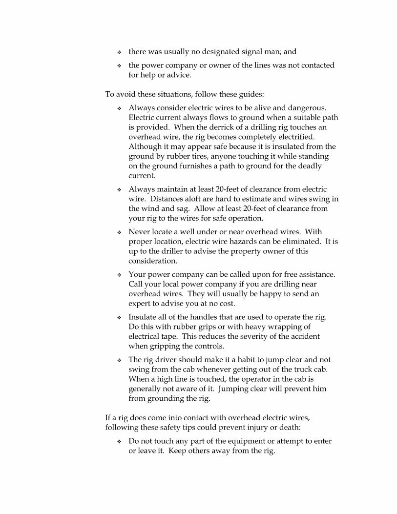
there was usually no designated signal man; and
the power company or owner of the lines was not contacted for help or advice.
To avoid these situations, follow these guides:
Always consider electric wires to be alive and dangerous. Electric current always flows to ground when a suitable path is provided. When the derrick of a drilling rig touches an overhead wire, the rig becomes completely electrified. Although it may appear safe because it is insulated from the ground by rubber tires, anyone touching it while standing on the ground furnishes a path to ground for the deadly current.
Always maintain at least 20-feet of clearance from electric wire. Distances aloft are hard to estimate and wires swing in the wind and sag. Allow at least 20-feet of clearance from your rig to the wires for safe operation.
Never locate a well under or near overhead wires. With proper location, electric wire hazards can be eliminated. It is up to the driller to advise the property owner of this consideration.
Your power company can be called upon for free assistance. Call your local power company if you are drilling near overhead wires. They will usually be happy to send an expert to advise you at no cost.
Insulate all of the handles that are used to operate the rig. Do this with rubber grips or with heavy wrapping of electrical tape. This reduces the severity of the accident when gripping the controls.
The rig driver should make it a habit to jump clear and not swing from the cab whenever getting out of the truck cab. When a high line is touched, the operator in the cab is generally not aware of it. Jumping clear will prevent him from grounding the rig.
If a rig does come into contact with overhead electric wires, following these safety tips could prevent injury or death:
Do not touch any part of the equipment or attempt to enter or leave it. Keep others away from the rig.

Have someone call the local power company and local fire rescue squad immediately for their assistance.
Do not touch any person who may be in contact with the electrical current.
Only when life is at stake should a rescue be attempted. If a rescue is attempted, use a dry, clean rope or a dry, unpainted wood pole to remove the victim. Keep as far away as possible. Do not touch the victim until he is fully removed.
4.1.4 Hydraulic Lines
Hydraulic lines may have between 2800 and 3000-pounds per
square inch (psi) of pressure when pressurized. If a line ruptures, high velocity hydraulic oil could blow on a worker, causing injury to the eyes. A ruptured line could also whip wildly during pressure release, causing severe injury and even decapitation. If there is no reason to be around a rig, don’t be there!
4.1.5 Inhalation Hazards
When drill crews grout, much dust is generated. Portland cement
is one ingredient of grout. Read the warning labels of the Portland cement. Use respirators.
4.1.6 Ergonomics
Backs/lifting techniques; nice to help but be selective. 4.1.7 Miscellaneous
Steep slopes are especially hazardous; cribbing must be level and solid. Ensure proper jacking and leveling techniques.
Chain could break on air rotary; chain whips straight out the back.
Drill rods can fall out of carousel on air rotary rig if rod is riding high and the small diameter section of rod is in line with the holding mechanism.
Wire rope can fail, causing the rope to snap and cause serious injury.

There are many pinch points on a drill rig; serious injury to fingers and hands can result.
Wet rope grips tight on cat head.
Check valve on hydraulic line to jacks fail, causing rig to fall on that side.
Weight of rig, combined with unstable soil/rock may cause cave in and rig to fall in hole.
Loose clothing, such as draw strings on jackets and hood can get caught in machinery.
Drugs.
Prescription drugs, over-the-counter drugs, illegal drugs, and
alcohol have an effect on our bodies. They can effect our motor coordination, concentration, and temper. It is extremely important to avoid using any type of drug while engaged in such a dangerous operation as drilling. Any safety officer or supervisor should not permit anyone to work on a Site when someone is under the influence of drugs.
Other under ground utilities
o Propane
o Sewer
o Telephone
o Cable
o Gas 4.1.8 Carelessness
Mondays, Fridays, late Site departures, schedule short falls, drill
crew/consultant/client animosity, when there is a new helper, and inclement weather are all times when safe drilling is most likely to be compromised. Be aware of these danger times and make a conscious and concerted effort to have a safe Site.
4.2 PREVENTATIVE AND CORRECTIVE ACTIONS 4.2.1 Rig Emergency Shut Down

On all rigs you will find at least one emergency shut down switch, commonly referred to as a “kill switch”. The drill rig crew should test this switch at the beginning of each day. All personnel should know at least where this switch is and how to use it. Do not ever touch levers except in emergencies; use the “kill switch” when an injury has occurred.
4.2.2 Tailgate Meetings 4.2.2.1 Proper monitoring techniques
How long on this particular rig?
Awareness of rig exhaust; shut down rig if needed.
Helper – BZ is low to the ground.
Ensure Operator sees you.
Type of Site and weather - work environment. 4.2.2.2 Expectations and Standards
Their health and safety equipment.
They are responsible to inform you of their observances. 4.2.2.3 Coordination of Cooperation
Teamwork concept.
Decrease confusion and chance of an accident by establishing a perimeter and zones. Use caution tape, stakes, and cones to delineate these perimeters and zones.
STANDARD OPERATING PROCEDURE SOP #: 5 Title: Heat Stress Last Rev.: 12/31/07
Page: 1 of 4 SCOPE This procedure provides work practices to minimize the impact of heat stress caused by exposure to hot environments or working conditions. DEFINITIONS
• Acclimatization – The ability to adjust to hot working conditions. This adjustment to heat, under normal circumstances, usually takes about 5 to 7 days, during which time the body will undergo a series of changes that will make continued exposure to heat more endurable.
• Heat Index – An accurate measure of how hot it really feels when relative humidity
(RH) is added to the actual air temperature. PROCEDURE A. The Site Safety Officer will implement techniques for preventing heat stress-related
health issues. Prevention techniques include: 1. Provide shaded areas with cross-ventilation, if possible, for lunch and breaks. 2. Schedule physically demanding and strenuous tasks, or tasks requiring full-body
chemical protection, for early in the day, if possible. 3. Drink at least 6-8 ounces of cool water every 60 minutes. 4. Use the buddy system and look for signs of heat stress. Any employee with
signs of heat stress must immediately proceed to the break area. Signs and symptoms for various heat stress disorders and recommended first aid are listed in the following table.

STANDARD OPERATING PROCEDURE SOP #: 5 Title: Heat Stress Last Rev.: 12/31/07
Page: 2 of 4
Disorder Symptoms Cause Prevention/First Aid Heat Rash or Prickly Heat
♦ Rash ♦ Itching
♦ Hot, humid conditions ♦ Sweat doesn’t
evaporate easily ♦ Sweat ducts become
clogged
♦ Ointments ♦ Keep skin clean and dry ♦ Good daily personal hygiene
Heat Cramps
♦ Sudden onset of muscle cramps usually in legs or arms
♦ Hot, moist skin ♦ Normal pulse ♦ Normal or slightly elevated
temperature
♦ Loss of water (sweating)
♦ Loss of electrolytes ♦ Replacing water but
not electrolytes
♦ Move into shade ♦ Loosen clothing ♦ Drink tepid electrolyte drinks
or water ♦ Seek medical assistance if
conditions persist
Heat Exhaustion
♦ Pale, clammy skin ♦ Profuse perspiration ♦ Thirst from dehydration ♦ Weakness ♦ Headache ♦ Nausea ♦ Loss of coordination
♦ Overexertion ♦ Excessive loss of water
and electrolytes
♦ Move into shade ♦ Remove PPE ♦ Loosen street clothing ♦ Cool by applying damp cool
compresses or ice packs ♦ Drink tepid electrolyte drinks
or water ♦ Summon medical assistance
Heat Stroke ♦ Elevated temperature (>103F)
♦ Flushed, hot, dry skin ♦ Absence of sweating ♦ Delirious ♦ Rapid pulse ♦ Nausea ♦ Headache ♦ Dizziness ♦ Unconsciousness
♦ Failure of body’s cooling (sweating) mechanism
♦ Summon medical assistance ♦ Move to shade ♦ Remove PPE ♦ Loosen street clothing ♦ Cool by fanning or applying
damp compress or ice packs
5. The Site Safety Officer must verify that a work-rest cycle based on the heat index
is implemented for site workers as applicable. Refer to the following three tables. To use the chart, read the temperature at the left and humidity across the top, the heat index is where the two intersect. For example, with a temperature of 96 and a humidity of 50%, the Heat Index is 108. Determine what the associated risk level is, based on the heat index. Use the risk level and heat index to determine the appropriate work-rest cycle.

STANDARD OPERATING PROCEDURE SOP #: 5 Title: Heat Stress Last Rev.: 12/31/07
Page: 3 of 4 Heat Index Chart
Relative Humidity (%) 40 45 50 55 60 65 70 75 80 85 90 95 100 110 136 108 130 137 106 124 130 137 104 119 124 131 137 102 114 119 124 130 137 100 109 114 118 124 129 136 98 105 109 113 117 123 128 134 96 101 104 108 112 116 121 126 132 94 97 100 102 106 110 114 119 124 129 136 92 94 96 99 101 105 108 112 116 121 126 131 90 91 93 95 97 100 103 106 109 113 117 122 127 132 88 88 89 91 93 95 98 100 103 106 110 113 117 121 86 85 87 88 89 91 93 95 97 100 102 106 108 112 84 83 84 85 86 88 89 90 92 94 96 98 100 103 82 81 82 83 84 84 85 86 88 89 90 91 93 95
Tem
per
atu
re (F
)
80 80 80 81 81 82 82 83 84 84 85 86 86 87 Heat Index Risk Level and Associated Health Effects
Heat Index Associated Risk >130 Extreme Danger
Heat stroke highly likely with continued exposure 105-130 Danger
Heat exhaustion and heat cramps likely and heat stroke possible with prolonged exposure and/or physical activity
90-105 Extreme Caution Heat cramps and heat exhaustion possible with prolonged exposure and/or physical activity
80-90 Caution Fatigue possible with prolonged exposure and/or physical activity
NOTES:
• Heat Index values were devised for shady, light wind conditions. Exposure to full sun may increase these values by up to 15º.
• Heat Index values were devised for the general public wearing typical lightweight summer clothing. Acclimatized workers may be able to work under conditions with a slightly higher Heat Index.
• The use of personal protective equipment, including clothing increases the heat stress load on the body.

STANDARD OPERATING PROCEDURE SOP #: 5 Title: Heat Stress Last Rev.: 12/31/07
Page: 4 of 4 The work-rest cycle outlined below should be implemented based on the professional judgment of the Site Safety Officer and/or the Project Health and Safety Consultant. Workers must drink 8 ounces of cool water at each break.
Heat Index Risk Level Work-Rest Cycle > 130 Extreme Danger 15 minute break every 30 minutes 105-130 Danger 15 minute break every 60 minutes 90-105 Extreme Caution 15 minute break every 90 minutes 80-90 Caution 15 minute break every 120 minutes
B. The Site Safety Officer and the Construction Manager will observe workers to verify
compliance with and effectiveness of prevention techniques. C. The Site Safety Officer should provide first aid treatment for heat stress related health
issues. D. In the event a heat stress related incident occurs, the Site Safety Officer will report the
incident following guidelines in the HASP. REFERENCES Regulatory References None Technical References
• NOAA – National Weather Service, Heat Index, Measure of How Hot it Feels Procedural References None REVISION LOG
DATE REV. # APV’D COMMENTS 12/31/07 0 ELG Issued for use
STANDARD OPERATING PROCEDURE SOP #: 7 Title: Natural Hazards Last Rev.: 12/31/07
Page: 1 of 20
SCOPE This procedure provides guidance for determining appropriate means for handling natural hazards that may be encountered while conducting fieldwork. DEFINITIONS None. PROCEDURE Potential exposure natural hazards during performance of this project is believed to be minimal. However since the work is performed outside some precautions should be taken to guard against the following hazards. Keep in mind that the hazards may vary depending on the time of year or geographical region. Infrequent hard freezes may allow insects and snakes to be active all year round in some parts of the United States. Refer to Attachments 1 through 3 for photos and more thorough descriptions of the more common natural hazards, which might be encountered. A. Identify type of natural hazard present. B. When a natural hazard (such as poisonous plants, feral animals, insects and snakes) is
encountered, back away and evaluate the situation. C. Develop a plan which may include any of the following:
1. Remove the natural hazard if it can be done safely.
2. Avoid the natural hazard if it cannot be removed. Additionally, use appropriate PPE or outer clothing for protection from the hazard. Refer to SOP – 8, Personal Protective Equipment.
3. Get assistance in removing or working around the natural hazard. In some instances, this may require professional help from animal control or an insect expert.
D. In the event there is contact with the natural hazard, if it appears to be a life threatening
situation, such as anaphylactic shock or a snake bite, seek medical attention immediately.
- OR -

STANDARD OPERATING PROCEDURE SOP #: 7 Title: Natural Hazards Last Rev.: 12/31/07
Page: 2 of 20
A. POISONOUS PLANTS
1. Poison ivy is in the form of a vine, while oak and sumac are bush-like.
2. All produce a delayed allergic hypersensitivity.
3. The plant tissues have an oleoresin, which is active in live, dead, and dried parts and may be carried through dust, contaminated articles, and the hair of animals.
4. Symptoms usually occur 24 to 48 hours after exposure resulting in burning or stinging, and weeping and/or crusted blisters.
5. The best antidote for poisonous plants is recognition and avoidance.
6. Should exposure to any of these plants occur, notify the Site Safety Officer and wash the affected area with a mild soap and water, but do not scrub the area.
B. TICKS
1. Ticks attach to their host's skin and intravenously feed on its blood creating an opportunity for disease transmission.
2. Covering exposed areas of the body and the use of tick repellent are two ways to prevent tick bites.
3. Periodically during the workday employees should inspect themselves for the presence of ticks.
4. Notify the Site Safety Officer of any tick bites as soon as possible, medical attention may be required.
C. SPIDERS
1. Black Widow
a. The black widow is a common venomous spider found in vacant rodent burrows, under stones, logs and long grass, and in hollow stumps and brush piles.
b. If disturbed, they typically will retreat to a corner of their web but can be induced to bite only if pressed against the skin.
c. Notify the Site Safety Officer if bitten, because neurotoxins are injected, it is important to seek immediate medical attention.
2. Brown Recluse
a. The brown recluse or Fiddle Back Spider is another common venomous spider.

STANDARD OPERATING PROCEDURE SOP #: 7 Title: Natural Hazards Last Rev.: 12/31/07
Page: 3 of 20
b. It hides in dark niches and corners, where it may spin a poorly organized,
irregular web.
c. It is shy and will try to run from a threatening situation but will bite if cornered.
d. Check boots and protective clothing for spiders prior to putting them.
e. The bite of the brown recluse is usually painless until 3 to 8 hours later when it may become red, swollen, and tender. Notify the Site Safety Officer if bitten.
f. Prompt medical attention can reduce the extent of ulceration and alleviate other complications that may develop.
D. FIRE ANTS
1. One sure sign of the presence of fire ants is their conical mounds, which are a result of the digging of their chambers.
2. The sting of a fire ant results in localized reddening of the bite area, accompanied by sharp burning sensations.
3. The first ant sting releases a chemical substance that triggers other ants of the colony to sting.
4. Anyone seeing fire ant mounds present at the work site should notify the Site Safety Officer, who will then notify the rest of the crew so the mounds may be avoided if possible.
E. CHIGGERS
1. Chiggers, also known as “red-bugs” or “harvest mites”, are the immature stages of a tiny red mite.
2. They inhabit areas of tall grass, associated with low, wet spots, ponds and stream banks, wild berry patches, and forest underbrush.
3. The larvae attach themselves to the clothing of people or to the fur of passing animals.
4. Wear loose-fitting clothing (if possible) when working outdoors. Apply a repellent containing DEET (N,N-diethyl-meta-toluamide), to shoes, socks, and trousers before entering chigger-infested areas. Caution: some individuals may be sensitive to DEET – always read and follow label directions
5. Vehicles should be frequently vacuumed to reduce the number of chiggers that may have been deposited.

STANDARD OPERATING PROCEDURE SOP #: 7 Title: Natural Hazards Last Rev.: 12/31/07
Page: 4 of 20
6. Flowers of sulfur is another repellant of chiggers. Sulfur may be more benign to
use than DEET on some body parts. Avoid breathing dust during application.
F. FLYING INSECTS
1. Flying insects such as mosquitoes, wasps, hornets, and bees may be encountered while site activities occur.
2. Wear long-sleeved clothes and long pants treated with repellent. Do not treat unexposed skin. Use the repellent according to the manufacturer’s recommendations provided on the container.
3. Personnel should report flu-like symptoms to the Site Safety Officer, medical attention may be needed.
G. SNAKES
1. The most effective way to prevent snakebites is to avoid snakes.
2. Personnel should avoid walking in high grass and underbrush.
3. Visual inspection of work areas should be performed prior to activities taking place.
4. The use of leather boots and long pants will be required, since more than half of all bites are on the lower part of the leg.
5. No attempts at killing snakes should be made; many people are bitten in such an attempt.
6. If a snake bites someone, Notify the Site Safety Officer and seek medical services.
H. ALLIGATORS
1. Never approach an alligator. Always stay at least 30 yards away. Never wade or swim in areas that could contain large alligators.
2. Do not dump food or scraps into or near the water. This can attract alligators.
3. Always be aware of your surroundings and use caution and common sense.
4. If at any time personnel observe alligators at the site they will immediately inform the Site Safety Officer or Construction Manager, who will then notify the rest of the employees and local wildlife personnel.

STANDARD OPERATING PROCEDURE SOP #: 7 Title: Natural Hazards Last Rev.: 12/31/07
Page: 5 of 20
I. FERAL ANIMALS
1. Feral animals such as rats or other wildlife may be encountered during
fieldwork.
2. If an animal is diseased, injured or tending a nest, they may become aggressive.
3. Notify the Site Safety Officer or Construction Manager if feral animals are at the site, who will then notify the rest of the employees and local wildlife personnel.
ATTACHMENTS Attachment 1, Poisonous Plants Attachment 2, Insects Attachment 3, Snakes Attachment 4, Other Natural Hazards REFERENCES Regulatory References None Technical References None Procedural References SOP – 8, Personal Protective Equipment REVISION LOG
DATE REV. # APV’D COMMENTS 12/31/07 0 ELG Issued for use

STANDARD OPERATING PROCEDURE SOP #: 7 Title: Natural Hazards Last Rev.: 12/31/07
Page: 6 of 20
Attachment 1
Poisonous Plants Most species of poison ivy, oak, and sumac have three leaflets; hence, the saying, "Leaves of three, let it be." These plants vary significantly in appearance in different regions of the country, but in most species the flower and fruit structures arise in the angle between the leaf and the twig, the flowers are greenish in spring, and the plant's mature fruit is off-white or pale yellow-green. Several varieties, including two species each of poison ivy, poison oak, and poison sumac and six subspecies of poison ivy (Toxicodendron radicans), are found in the United States. Poison ivy (see figure A below) generally grows east of the Rocky Mountains and poison oak in the West. Both poison ivy and poison sumac are found along the Gulf Coast. Poison oak prefers swampy areas in the Southeast.

STANDARD OPERATING PROCEDURE SOP #: 7 Title: Natural Hazards Last Rev.: 12/31/07
Page: 7 of 20
A climbing vine with three serrated-edge, pointed leaves grows in the East, Midwest and South. In the northern and western states, poison ivy grows as a non-climbing shrub. The appearance of these plants is variable. Leaves are alternate and normally consist of three leaflets with the stalk of the central leaflet being longer than those of the other two are but can be found with five or even seven leaflets. The leaflets are two to four inches long, dull or glossy green with pointed tips. The middle leaflet is generally larger than the two laterals. The edges of the leaflets may be toothed, lobed, or smooth. Virginia Creeper (Parthenocissus quinquefolia) is non-poisonous vine with five leaflets that is often mistaken for poison ivy. Poison ivy can be a shrub or a woody vine. Yellowish-green flowers occur in compact clusters in leaf axils, in June or July followed by waxy, gray-white berries about three-sixteenths of an inch in diameter in late summer.

STANDARD OPERATING PROCEDURE SOP #: 7 Title: Natural Hazards Last Rev.: 12/31/07
Page: 8 of 20

STANDARD OPERATING PROCEDURE SOP #: 7 Title: Natural Hazards Last Rev.: 12/31/07
Page: 9 of 20
Poison oak also has three leaves. It grows in the sandy soil of the Southeast as a small shrub. In the western United States poison oak is a very large plant that grows as a standing shrub or climbing vine. Eastern poison oak has the most "oak-looking" leaves of any of the species. It usually has multi-lobed leaves, no aerial roots on the stems, and fuzzy fruits and leaves. It loves sandy soils. Western poison oak is found only along the Pacific coast and into the mountains and it usually has aerial roots extending from the main stem.

STANDARD OPERATING PROCEDURE SOP #: 7 Title: Natural Hazards Last Rev.: 12/31/07
Page: 10 of 20
A shrub or bush with two rows of 7-13 leaflets, most common in the peat bogs of the Northern United States and in swampy Southern regions of the country. A water loving swamp shrub (dendritic) or bush with two rows of 7-13 leaflets; growing from 6 to 20 feet in height, the Poison Sumac is found in the east from Quebec to Florida and westward along the coast to far west Texas between Shelby and Hardin counties.
Listed below are recommended actions to take to reduce the potential exposure to poisonous plant: • Determine what types of poisonous plants may be present at the specific site.
• Use repellant sprays and coatings.
• Use netting or long sleeves with cuffs and long pants.
• Regularly inspect skin.
• Maintain a first aid kit on hand.

STANDARD OPERATING PROCEDURE SOP #: 7 Title: Natural Hazards Last Rev.: [x]
Page: 11 of 20
Attachment 2
Insects Chiggers
Chiggers, also known as “red-bugs” or “harvest mites”, are the immature stages of a tiny red mite. They inhabit areas of tall grass, associated with low, wet spots, ponds and stream banks, wild berry patches, and forest underbrush. The larvae attach themselves to the clothing of people or to the fur of passing animals. Before settling down to feed, chiggers move to a constriction, such as sock tops, waistbands, or armpits. Feeding chiggers inject a salivary fluid, which dissolves the host’s cells, and then they suck up the liquefied tissue. Within a few hours, small, reddish, intensely itching welts appear. These bites may continue to itch for several days up to two weeks after the chigger is dislodged. Following are suggestions that should provide some protection from chiggers:
• Stay out of areas where chiggers are likely to be present including wood lots, pastures, roadside ditches, or other areas with tall grasses and weeds. Chiggers are especially common in moist low-lying areas.
• Wear loose-fitting clothing (if possible) when working outdoors. Vehicles should be frequently vacuumed to reduce the number of chiggers that may have been deposited.
• Apply a repellent containing DEET to shoes, socks, and trousers before entering chigger-infested areas. Caution: some individuals may be sensitive to DEET – always read and follow label directions.
• Another repellant of chiggers is flowers of sulfur. Flowers of sulfur is powdered elemental sulfur available at a drug store or pharmacy as an over-the-counter preparation. It has a slight, rotten egg smell. Areas on the body that have tight clothing up against them such as socks, waistbands, etc. may be dusted with sulfur powder. Surveyors and other field personnel state that they fill a sock with sulfur and are able to dust these areas efficiently.

STANDARD OPERATING PROCEDURE SOP #: 7 Title: Natural Hazards Last Rev.: [x]
Page: 12 of 20
Sulfur may be more benign to use than DEET on some body parts. Avoid breathing dust during application.
• Immediately after possible exposure to chiggers, take a bath, thoroughly scrubbing the body with hot soapy water. This will kill or dislodge many of the chiggers. The clothes that were worn when the bite(s) occurred should be placed in a plastic bag for temporary storage until they can be laundered.
• When bites begin to itch, one course of treatment is to apply rubbing alcohol, followed by one of the nonprescription local anesthetics. A baking soda paste, calamine lotion, or product such as “After-Bite” also will help reduce discomfort. Avoid scratching bites since this only increases irritation and may lead to a secondary infection of the bite.
Ticks Ticks are vectors of many different diseases including Rocky Mountain spotted fever, Q fever, tularemia, Colorado tick fever, and Lyme disease. They attach to their host's skin and intravenously feed on its blood creating an opportunity for disease transmission. Covering exposed areas of the body and the use of tick repellent are two ways to prevent tick bites. Periodically during the workday employees will inspect themselves for the presence of ticks. If a tick is discovered, the following procedure should be used to remove it:
• Do not try to detach a tick with your bare fingers; bacteria from a crushed tick may be able to penetrate even unbroken skin. Fine-tipped tweezers should be used.
• Grip the tick as close to your skin as possible and gently pull it straight away from you until it releases its hold.
• Do not twist the tick as you pull and do not squeeze its bloated body. That may actually inject bacteria into your skin.
• Thoroughly wash your hands and the bite area with soap and water. Then apply an antiseptic to the bite area.
• Save the tick in a small container with the date, the body location of the bite, and where you think the tick came from.
• Notify the SSO of any tick bites as soon as possible.
Recently, Lyme disease has been the most prevalent type of disease transmitted by ticks in the United States.

STANDARD OPERATING PROCEDURE SOP #: 7 Title: Natural Hazards Last Rev.: [x]
Page: 13 of 20
Spiders
A common venomous spider is the Black Widow. The adult female is glossy black with short, almost microscopic hairs and a crimson hourglass marking on the underside of the abdomen. They are found in dark corners of barns, stables, garages and piles of boxes and crates. They have also been known to reside in vacant rodent burrows, under stones, logs and long grass, and in hollow stumps and brush piles. Generally, Black Widows are not aggressive and usually can be induced to bite only if pressed against the skin. If disturbed, they typically will retreat to a corner of their web. However, these spiders are more aggressive if they are protecting an egg sac. After a bite, a dull numbing pain in the affected extremity occurs. In addition, pain and some muscular rigidity in the abdomen or the shoulder, back, and chest may occur. The bite may also produce headache, dizziness, skin rash, nausea, vomiting, anxiety and weakness, and increased skin temperature over the affected area may be observed. Ice may be placed over the bite to reduce the pain. Bites are rarely fatal to adults, but because the black widow spider injects neurotoxins, it is important to seek immediate medical attention.
Another venomous spider common in the southern United States is the Brown Recluse or Fiddle Back Spider. The Brown Recluse is about 1/4 to 1/2 inches in body length (most adults are about the size of a United States dime to a US quarter with legs extended). Coloration ranges from tan to dark brown, with the abdomen often darker than the rest of the body. The feature that most distinguishes the brown recluse from many other harmless spiders is a
STANDARD OPERATING PROCEDURE SOP #: 7 Title: Natural Hazards Last Rev.: [x]
Page: 14 of 20
somewhat darker violin-shaped marking on top of the leg-bearing section of the body. The neck of the violin "silhouette" points towards the rear (abdomen) of the spider. The brown recluse roams at night seeking its prey. During the day, it hides in dark niches and corners, where it may spin a poorly organized, irregular web. Eggs are deposited in 1/2 inch long off-white silken egg sacs, often appearing flattened beneath and convex above. It is shy and will try to run from a threatening situation but will bite if cornered. People are sometimes bitten while they are asleep because they roll onto a brown recluse spider while it is hunting in the bed. More often the victim is bitten while putting on a shoe or piece of clothing that a spider has selected for its daytime hiding place. The bite of the brown recluse is usually painless until 3 to 8 hours later when it may become red, swollen, and tender. Later the area around the bite site may develop into an ulcerous sore from 1/2 to 10 inches in diameter. Healing often requires a month or longer, and the victim may be left with a deep scar. Prompt medical attention can reduce the extent of ulceration and alleviate other complications that may develop. It should be noted that not all brown recluse bites result in ulcerations or scarring.1 Fire Ants Fire ants are approximately 1/4-inch long and live in underground chambers that typically contain over 1,000 ants. One sure sign of the presence of fire ants is their conical mounds, which are a result of the digging of their chambers. The sting of a fire ant results in localized reddening of the bite area, accompanied by sharp burning sensations. The first ant sting releases a chemical substance that triggers other ants of the colony to sting. Anyone seeing fire ant mounds present at the work site should notify the SSHO, who will then notify the rest of the crew so the mounds may be avoided if possible. Flying Insects Flying insects such as mosquitoes, wasps, hornets, and bees may be encountered while site activities occur. Section 3.4.4 discusses problems associated with them. Mosquitoes can be the vectors for diseases such as the West Nile Virus and Saint Louis Encephalitis, reports of which appear in the media periodically. Avoiding mosquito bites is the best way to avoid potential exposure to mosquito-borne disease. Apply insect repellant containing DEET (N,N-diethyl-meta-toluamide), wear long-sleeved clothes and long pants treated with repellent and stay indoors during peak mosquito feeding hours (dusk until dawn) to further reduce your risk. There is currently no vaccine to protect humans against Saint Louis Encephalitis or West Nile Virus. Individuals at project sites can reduce their risk from being infected with West Nile Virus by taking the following actions to protect against mosquito bites: • Review the hazards of West Nile Virus periodically in morning safety meetings.
• Increase protective measures when working at dawn, dusk, and in the early evening.
• Reduce the area of exposed skin when working outdoors. Long-sleeved shirts with sleeves rolled down are recommended. Understand that mosquitoes may bite through thin clothing, so personnel should evaluate the actual Level D clothing worn, for example, heavy, long
STANDARD OPERATING PROCEDURE SOP #: 7 Title: Natural Hazards Last Rev.: [x]
Page: 15 of 20
sleeve work shirts and heavy dungarees/jeans may be indicated. Activity at projects where disposable coverall use (i.e., Tyvek®) is specified, further reduces the risk of mosquito bites.
• For activities where only Level D PPE is specified, consider using disposable coveralls when working in wooded, highly vegetated, or swampy areas.
• Use an insect repellent containing approximately 30 percent DEET. In concentrations greater than 35 percent, DEET provides no additional protection. Use the repellent according to the manufacturer’s directions provided on the container. Use just enough repellent to cover exposed skin and clothing. Do not treat unexposed skin. Frequent reapplication or saturation is unnecessary for effectiveness. Avoid prolonged and excessive use of DEET.
• When additional protection against mosquitoes is necessary, commercially prepared “clothing and gear” insect repellants containing 0.5 percent permethrin may be used. These repellants, such as Repel Permanone™ are available in the sporting goods departments at major retailers. Clothing and gear insect repellants are not for use on skin. Use the repellent according to the manufacturer’s recommendations provided on the container.
• After returning from outdoor field activities, wash treated skin with soap and water.
• Personnel should report flu-like symptoms to the SSO.
West Nile Virus The Centers for Disease Control and Prevention report that human illness from West Nile virus is rare, even in areas where the virus has been reported. The chance that any one person is going to become ill from a mosquito bite is low. West Nile virus is spread by the bite of an infected mosquito, and can infect people, horses, many types of birds, and some other animals. Most people who become infected with West Nile virus will have either no symptoms or only mild ones. On rare occasions, West Nile virus infection can result in a severe and sometimes fatal illness known as West Nile encephalitis (an inflammation of the brain). The risk of severe disease is higher for persons 50 years of age and older. There is no evidence to suggest that West Nile virus can be spread from person to person or from animal to person. Saint Louis Encephalitis The Centers for Disease Control and Prevention report mild infections occur without apparent symptoms other than fever with headache. More severe infection is marked by headache, high fever, neck stiffness, stupor, disorientation, coma, tremors, occasional convulsions (especially in infants) and spastic paralysis. There is no evidence to suggest that Saint Louis encephalitis can be spread from person to person or from animal to person.

STANDARD OPERATING PROCEDURE SOP #: 7 Title: Natural Hazards Last Rev.: [x]
Page: 16 of 20
Table 1
Flying Insect Information
Organism Description Habitat Problem Severity Protection
Hornet One inch long with some body hair. Abdomen is mostly black.
Round, paper like nest hanging from trees, shrubs, or under eaves of buildings.
One nest may contain up to 100,000 hornets that will attack in force at the slightest provocation.
Severe pain, allergic reactions similar to bees.
Do not come near or disturb nest. If a hornet investigates you, do not move.
Mosquito Small, dark, fragile body with transparent wings. From 1/8 to 1/4 inch long.
Where water is available for breeding.
Bites and sucks blood. Itching and swelling result.
Can transmit encephalitis and other diseases. Scratching causes secondary infections.
Use plenty of insect repellant and wear gloves. Stay in windy areas.
Wasp Very thin waist. Color can be black, yellow or orange with stripes.
Underground nest. Paper-like honeycomb nest in abandoned buildings hollow trees, etc.
Stings. Some species will attack if you get too close to the nest.
Severe pain, allergic reactions similar to bees. Can be fatal.
Avoid Nest. Do not swat at them.
Bee Generally have yellow and black stripes and two pair of wings.
Hollow logs, underground nest, old buildings,
Stings when annoyed. Leaves venom sac in victim.
If person is allergic, nausea, shock, constriction of the airway can result. Death may result.
Be careful and watch where you walk. Cover exposed skin. Avoid areas where bees are swarming. Avoid wearing sweet fragrances and bright clothing. Move slowly or stand still when bees are swarming about you.

STANDARD OPERATING PROCEDURE SOP #: 7 Title: Natural Hazards Last Rev.: 12/31/07
Page: 17 of 20
Attachment 3
Snakes Copperhead
Coral
Cottonmouth
Diamondback Rattlesnake
Water Moccasin The most effective way to prevent snakebites is to avoid snakes in the first place. Personnel should avoid walking at night or in high grass and underbrush. Visual inspection of work areas should be performed prior to activities taking place. The use of leather boots and long pants will be required, since more than half of all bites are on the lower part of the leg. No attempts at killing snakes should be made; many people are bitten in such an attempt.
If a snake bites someone, the following treatment should be initiated:
• Keep patient calm

STANDARD OPERATING PROCEDURE SOP #: 7 Title: Natural Hazards Last Rev.: 12/31/07
Page: 18 of 20
• Notify emergency medical services
• Wash the wound and keep the affected body part still
• Apply direct pressure to site of bite if bleeding is extreme
• Keep the affected area lower than the heart
• Carry a victim who must be transported, or have him/her walk slowly
• Transport to closest medical facility

STANDARD OPERATING PROCEDURE SOP #: 7 Title: Natural Hazards Last Rev.: [x]
Page: 19 of 20
Attachment 4
Other Natural Hazards Alligators Alligators live in nearly all Louisiana parishes but are most common in the major river drainage basins and large lakes in the southern portion of the state. Most attacks involve animals over six feet long. Alligators become more active in the beginning of March, peaking in May, which is their mating season. Females will nest in June - July, and the eggs will hatch in August and September. Even a small amount of impounded water may contain a large alligator. Twilight and night are prime times for alligator attacks. Never approach an alligator. Always stay at least 30 yards away. Never wade or swim in areas that could contain large alligators. Do not dump food or scraps into or near the water. This can attract alligators. Always be aware of your surroundings and use caution and common sense. If at any time personnel observe alligators at the site they will immediately inform the SSO, who will then notify the rest of the crew and local wildlife personnel. Feral Animals Feral animals such as rats or other wildlife may be encountered during fieldwork. Typically, feral animals are as afraid or more afraid of humans and when encountered will run away from human contact. However, if an animal is diseased, injured or tending a nest, they may become aggressive. The most common disease encountered with feral animals is rabies. Signs of a rabies-infected animal include: • Changes in an animal’s behavior;
• General sickness;
• Difficulty swallowing;
• An increase in drool or saliva;
• Wild animals that appear abnormally tame or sick;
• Animals that may bite at everything if excited;
• Difficulty moving or paralysis; and
• Death.
Animals in the early stage of rabies may not have any signs, although they can still infect you if
they bite you. The incubation period is the time from the animal bite to when signs appear. In rabies, it is usually 1-3 months. However, it can last as long as several years. Once the virus reaches the brain or spinal cord, signs of the disease appear. In the event

STANDARD OPERATING PROCEDURE SOP #: 7 Title: Natural Hazards Last Rev.: [x]
Page: 20 of 20
an animal is encountered on the site, do not approach it. If it exhibits one or more of the signs listed above, call local wildlife personnel to get as

STANDARD OPERATING PROCEDURE SOP #: 8 Title: Personal Protective Equipment Last Rev.: 12/31/07
Page: 1 of 3 SCOPE This procedure provides guidance for determining appropriate Personal Protective Equipment (PPE) to be worn at the job site, based on new tasks and chemical or physical agents identified in the field. The initial determination for proper PPE is completed as part of development of the HASP. DEFINITIONS None. PROCEDURE A. The Site Safety Officer will complete a hazard assessment of the tasks involved and
identify the appropriate PPE based on the task and the chemical or physical agents involved. The written hazard assessment certification must be documented in the HASP.
B. The Site Safety Officer will communicate to employees the PPE requirements for the
tasks involved. C. The Site Safety Officer will provide PPE that properly fits the employee(s). D. The site Safety Officer will conduct daily site walks to verify appropriate use of PPE. E. RCM Health & Safety Coordinator or the Site Safety Officer will provide training to the
employees which includes at least the following:
1. When PPE is necessary; 2. What PPE is necessary; 3. How to properly don, doff, adjust and wear PPE; 4. The limitations of the PPE; and 5. The proper care, maintenance, useful life and disposal of the PPE.
F. Re-training by the Site Safety Officer may be required if:
1. Changes at the job site make previous training obsolete. 2. Changes in the types of PPE make previous training obsolete. 3. Inadequacies in an affected employee’s knowledge or use of PPE indicate the
employee requires additional training. G. Types of PPE include the following:
1. Eye and Face Protection

STANDARD OPERATING PROCEDURE SOP #: 8 Title: Personal Protective Equipment Last Rev.: 12/31/07
Page: 2 of 3
a. All eye and face protection must comply with ANSI Z87.1-1989. b. Safety glasses
• Side shields must be worn when there is a hazard of flying objects. • Prescription glasses must meet the ANSI Z87.1-1989 requirements or
must have eye protection over them meeting the ANSI standard requirements.
c. Chemical goggles d. Face shield
2. Head Protection a. All head protection (hard hats) must comply with ANSI Z89.1-1989.
3. Foot Protection All foot protection must comply with ANSI Z41-1991. a. Safety-toed shoes b. Rubber boots or rubber safety-toed boots
4. Hand Protection Hand protection must be selected based on the performance characteristics of the hand protection relative to the task(s) to be performed, conditions present, duration of use and the hazards and potential hazards identified. The RCM Health and Safety Coordinator must verify and document selection of appropriate chemical resistant gloves.
a. Work gloves, such as leather or cotton b. Chemical gloves, such as nitrile, neoprene, Viton, butyl rubber c. Cut-resistant gloves, such as Kevlar
5. Hearing Protection a. Ear plugs b. Ear muffs
6. Respiratory Protection (Refer to SOP – 9)
7. Other PPE a. Disposable Coveralls b. Fire Resistant Clothing
REFERENCES Regulatory References
• 29 CFR 1910.132, Personal Protective Equipment, General Requirements • 29 CFR 1910.133, Eye and Face Protection • 29 CFR 1910.135, Head Protection

STANDARD OPERATING PROCEDURE SOP #: 8 Title: Personal Protective Equipment Last Rev.: 12/31/07
Page: 3 of 3
• 29 CFR 1910.136, Foot Protection • 29 CFR 1910.138, Hand Protection
Technical References • ANSI Z87.1-1989, American National Standard Practice for Occupational and
Educational Eye and Face Protection • ANSI Z89.1-1989, American National Standard for Personal Protection – Protective
headwear for Industrial Workers – Requirements • ANSI Z41-1991, American National Standard for Personal Protection – Protective
Footwear
Procedural References • SOP – 9, Respiratory Protection
REVISION LOG
DATE REV. # APV’D COMMENTS 12/31/07 0 ELG Issued for use

STANDARD OPERATING PROCEDURE SOP #: 9 Title: Respiratory Protection Last Rev.: 12/31/07
Page: 1 of 4 SCOPE This procedure identifies the work practices and regulatory requirements with regard to respiratory protection. DEFINITIONS
• Escape Respirators – Respiratory devices providing protection only during escape from hazardous atmospheres.
• Hazardous Atmosphere - (1) Any atmosphere containing a toxic or disease-producing
gas, vapor, dust, fume, or mist, either immediately or not immediately dangerous to life or health; or (2) Any oxygen-deficient atmosphere.
• Immediately Dangerous to Life or Health (IDLH) – A condition that poses a threat of
exposure to airborne contaminants when that exposure is likely to cause death or immediate, or delayed, permanent adverse healths effects, or prevent escape from such an environment.
• Oxygen Deficient Atmosphere – An atmosphere containing less than 19.5 percent
oxygen by volume. PROCEDURE A. The Site Safety Officer must verify that all employees required to wear respiratory
protection at the jobsite are qualified (i.e., have completed a medical evaluation, been fit-tested and are trained.)
B. The RCM Health and Safety Coordinator will select respiratory protection based on the
hazards at the jobsite. Selection of respiratory protection will be completed as part of the hazard assessment when completing the HASP. If unanticipated conditions are encountered at the jobsite requiring a change in respiratory protection, follow the respiratory protection upgrade process defined Section 5 of in the site specific HASP. Additionally , the Site Safety Officer should contact the RCM Health and Safety Coordinator to re-evaluate PPE requirements
C. Inspection
1. All workers must inspect all non-emergency respirators before each use and during cleaning.
2. The Site Safety Officer must inspect respirators used for emergency use, at least monthly and in accordance with the manufacturer’s recommendations, and must check for proper function before and after each use. See Section G of this SOP for situations requiring emergency use respirators.

STANDARD OPERATING PROCEDURE SOP #: 9 Title: Respiratory Protection Last Rev.: 12/31/07
Page: 2 of 4
3. Respirator inspection shall include: • Check for tightness of connections. • Check condition of inlet coverings, head harness, valves, connecting tubes,
harness assembly, hoses, filter, cartridges, canisters, end-of-service-life indicator, electrical components, and shelf-life date(s).
• Check all rubber and elastomeric parts. • Check all air cylinders for proper charge. • For respirators maintained for emergency use, the inspection must be
documented with the date of the inspection, the name of the inspector, the findings, remedial action taken, and a serial number or other means if identifying the respirator. A tag or label must be affixed to the storage compartment and replaced with a subsequent inspection tag/label.
4. Any respirator that does not pass inspection shall be immediately removed from service to be repaired or replaced.
D. Use
1. No facial hair is allowed which could come between the sealing surface of the face piece and the face, or interfere with the valve function.
2. Eye protection must be worn such that it does not interfere with the face piece seal.
3. Conduct a seal-check (positive and negative pressure) every time the respirator is donned.
4. The Site Safety Officer must evaluate continuing respirator effectiveness • Maintain surveillance of work area to assess jobsite conditions and respirator
wearer(s) exposure or stress levels have not changed; • Direct respirator wearers to leave the work area:
− to wash their faces and face pieces to prevent eye or face irritation associated with respirator use;
− if a respirator wearer detects vapor or gas breakthrough, changes in breathing resistance or leakage of the face piece;
− to replace the respirator filter, cartridge or canister elements. • If a respirator wearer detects breakthrough, changes in breathing resistance
or leakage, they must replace or repair the respirator before returning to the work area. Change schedules for substances other than particulates will be addressed in the HASP or Job Hazard Analysis.
E. Maintenance
1. Clean and sanitize respirator after each use. 2. If respirators are not assigned, each respirator must be cleaned and sanitized
before being used by a different employee.

STANDARD OPERATING PROCEDURE SOP #: 9 Title: Respiratory Protection Last Rev.: 12/31/07
Page: 3 of 4
3. Respirators being used for emergency use shall be cleaned after being used. These respirators must contain a tag or label on them telling the last date they were inspected and who inspected them.
4. Each respirator shall be cleaned in warm water (not exceeding 1100F or 430C) with sanitizers that effectively clean the respirator and contain an antibacterial agent. For additional cleaning procedures, refer to 29 CFR 1910.134, Appendix B-2, Respirator Cleaning Procedures (Mandatory).
5. Replacement of parts or repairs may be done only by persons trained in proper respirator maintenance and assembly.
6. Replacement parts used shall be only those designated specifically for the respirator being repaired.
7. Any respiratory equipment not repairable, must be destroyed and discarded. F. Site workers must store respirators to protect them from:
1. physical damage including face piece or valve deformation; 2. contamination; 3. dust; 4. sunlight; 5. extreme temperatures; 6. excessive moisture; and 7. damaging chemicals.
G. Special Circumstances (including but not limited to Immediately Dangerous to Life and
Health (IDLH) or unknown concentrations)
If the Site Safety Officer or Construction Manager encounters special circumstances in the field which were not anticipated in the HASP, such as an IDLH atmosphere or an atmosphere with unknown concentrations or unknown constituents, contact your RCM Health and Safety Coordinator for assistance. Conditions requiring Self-Contained Breathing Apparatus (SCBA) or airline respiratory protection may require additional medical evaluation, fit-test of a different face piece and additional training. Additionally, when using supplied air, additional criteria apply regarding breathing air quality, quantity and flow. For additional information, refer to 29 CFR 1910.134(i).
REFERENCES Regulatory References
• 29 CFR 1910.134, Respiratory Protection Technical References None
STANDARD OPERATING PROCEDURE SOP #: 9 Title: Respiratory Protection Last Rev.: 12/31/07
Page: 4 of 4 Procedural References
• RCM Health and Safety Program, Appendix B, Section 1 REVISION LOG DATE REV. # APV’D COMMENTS 12/31/07 0 ELG Issued for use

STANDARD OPERATING PROCEDURE SOP #: 11 Title: Drum Handling Last Rev.: 12/31/07
Page: 1 of 2 SCOPE This procedure identifies the work practices and regulatory requirements regarding drum handling at the jobsite. DEFINITIONS None. PROCEDURE A. When handling drums, follow the general drum handling requirements listed below:
1. Hazardous substances and contaminated, liquids and other residues must be handled, transported, labeled, and disposed of in accordance with 29 CFR 1910.120(j).
2. When practical, drums and containers must be inspected and their integrity must be assured prior to being moved.
3. Unlabeled drums and containers must be considered to contain hazardous substances and handled accordingly until the contents are positively identified and labeled.
4. Drums must be handled only if necessary. Prior to handling, all personnel should be warned about the hazards of handling and instructed to minimize handling as much as possible.
5. Drums and containers that cannot be moved without rupture, leakage, or spillage must be emptied into a sound container using a device classified for the material being transferred.
6. A ground-penetrating system or other type of detection system or device will be used to estimate the location and depth of buried drums or containers.
7. Soil or covering material must be removed with caution to prevent drum or container rupture.
8. Fire extinguishing equipment meeting the requirements of 29 CFR Part 1910, Subpart L, must be on hand and ready for use to control incipient fires.
B. When opening drums and containers, such as for sampling or waste characterization
purposes, handling shock sensitive wastes, radioactive wastes, or when shipping drums, the RCM Health and Safety Coordinator must develop a site specific drum handling plan to be included in the HASP
REFERENCES Regulatory References
• 29 CFR 1910.120(j), Handling Drums and Containers

STANDARD OPERATING PROCEDURE SOP #: 11 Title: Drum Handling Last Rev.: 12/31/07
Page: 2 of 2
• 29 CFR 1926.65(j), Handling Drums and Containers Technical References None Procedural References
• ERM Corporate Health and Safety Program, Drum/Container/Cylinder Handling Procedures
REVISION LOG DATE REV. # APV’D COMMENTS 12/31/07 0 ELG Issued for use

19.0 PROCEDURES FOR THE COLLECTION OF ENVIRONMENTAL SAMPLES
The following discussion of procedures for the collection of environmental samples is divided into seven subsections. The first subsection discusses discrete and composite samples. The other subsection includes procedures for the sample collection of the following media: ground water, surface water, soils, sediment, biological and non-routine media.
19.1.1 TWO TYPES OF ENVIRONMENTAL SAMPLES
There are two general types of samples that can be collected: discrete (grab samples and composite samples. These types apply to all different sampling media. Discrete samples are collected at a single point in time, from a single location or over a discrete depth interval. Composite samples are taken from several different locations and depths, at several different times, or over a certain amount of water flow.
19.1.1 Discrete (Grab) Samples
Discrete samples must be collected under the same conditions for all constituents. All the water volume needed for a discrete monitoring well sample must be collected from the same depth in a well.
If more than one bailer full of water is necessary to fill the appropriate sample containers, then care must be exercised that the bailer is lowered to the same level in the well each time.
Discrete soil samples must, likewise, be collected from the same depth and location at each sampling point.
Discrete surface water samples must be collected from the same location and at one depth, to fill all the necessary sample containers.
19.1.2 Composite Samples
Samples can be composited based on sample volume, sample depth, sample weight, flow rates or time. Regardless of the criteria

determining the frequency of sample collection and the media being sampled, basic rules apply to all composite samples.
Samples to be analyzed for volatile organic compounds (VOCs) cannot be composited. Because compositing involves combining of the individual sub sample and this usually involves extra exposure to the air. Volatile organic constituents are lost in the compositing process.
Regardless of the media, equal parcels of sub-sample must be combined to form the composite. This may mean equal volumes of water from each sub-sample or equal weights of soil or sediment. For composites based on time or flow rates, equal volumes must be collected over constant intervals between sub samples.
Care must be exercised to insure that any sample implements used in the compositing process are thoroughly decontaminated, so that the representatives of each sub-sample are maintained.
The above guidelines can be applied to the collection of any of the six types of samples that are described in the following sections.
19.2 GROUND WATER SAMPLING
There are three types of wells from which ground water samples may be obtained; temporary wells, monitoring wells or residential wells, and municipal wells. Sampling from each of these will require the collection of different types of pre-sampling information and sampling equipment, as well as different sampling procedures. The sampling of monitoring wells is further divided into three subsections: (1) preparation for sampling; (2) well evacuation (purging); and (3) sample collection.
19.3 MONITORING WELLS 19.3.1 Preparation of Sampling
Prior to going to a Site, it is important to know the specifics of well construction, including:
well construction logs (if available);
inside diameter of the well casting;

total depth of well;
depth to the screened portion of the well;
screen length; and
the material used in the construction of the well and well screen.
Prior to sampling, it is imperative to locate all the wells on a Site map and determine the order in which each well will be sampled. If water quality information is available, the sampling order should proceed from the least contaminated to most contaminated well. Direction of anticipated or known ground water flow can be used to determine sampling order where no water quality information is available. Wells up-gradient of the source area should be sampled first, then proceed from the wells farthest down-gradient and work towards the source area.
The following is a list of equipment which may be needed when evacuating and sampling monitoring wells:
Sampling and Health & Safety Plans, and other Site specific documentation and information.
Appropriate sample containers.
Coolers and ice for sample preservation.
Meters, probes and standards for field measurements.
Pumps and/or bailers and associated tubing. The type of pump should be selected based on type of groundwater sampling (standard or low-flow sampling).
Water quality meter with flow cell and separate turbidity meter (for low flow-sampling only).
Proper PPE.
Appropriate quality control blanks. The type and number of blanks should be established with the project manager.
Chain-of-Custody labels, tags, and traffic report forms.
Decontamination solutions/water. These will be used for decontaminating all equipment that comes into contact with the monitoring well and samples.

Keys. Many monitoring wells will have locking caps and keys will be necessary to gain access. In addition, some Sites may be secured or may have a guard on duty, in which case keys and/or permission may be necessary.
Tools to assist in well access. These may include a turkey baster, screw drivers, hammers, chisels, pipe wrenches, bolt cutters, or possibly a propane torch. These may be necessary for removing standing water within the well protective casing or removing steel security caps on wells which have not been recently opened.
Tape measure graduated in tenths and hundredths of feet. A tape measure may be useful for measuring the diameter of the well casing and the elevation of the well casing above ground level.
Electronic water level indicator/graduated depth sounder and/or Interface Probe. These may be necessary for determining the static water level, thickness of floating product and the total depth of the well, if it is unknown.
Pocket calculator. This may be used for determining the volume of water within the well which, in turn, will be used for calculating the volume of water to be evacuated.
Five gallon buckets for purge water containment.
Log book and permanent ink marker. This is for recording information pertinent to the sampling procedures used and observations on the environmental conditions at the time of sampling.
Appropriate Groundwater Sampling Forms.
Thermally insulated cooler meters, photo-ionization detector (PID), etc.
Thermally insulated cooler. 19.3.2 Well Evacuation (Purging)
For standard groundwater sampling, it will be necessary to determine the volume of water being held in the well casing, prior to evacuating the well. The calculation of the well volume should be conducted as follows:
Measure well casing inside diameter.

Determine the static water level. This should be measured to the nearest one-hundredth of a foot below the measuring point evaluation. The top of the casing should be used as the measuring point and marked to standardize its location. (Note: The water level indicator must be cleaned before use in each well).
Determine the total depth of the well from the measuring point.
Calculate the number of linear feet of static water (total depth of the well minus the static water level.)
Calculate the static volume in gallons (πxr²xhx7.48 gal/ft³).
Where: π = 3.14 r = radius of well in feet h = number of linear feet in static water
Refer to Groundwater Sampling Record form for well volume conversion.
It is ERM’s policy that three well volumes be evacuated prior to sample collection or the stabilizing of low flow parameters. In most cases, removal of three well volumes should ensure the collection of a representative sample not influenced by stagnant water remaining in the well casing, and yet not result in over-pumping of the well. The latter can cause diluted or more concentrated ground water from another area within the aquifer to be pulled into the well. If the well goes dry during evacuation, allow it to recover and re-evacuate, if possible, until at least one and one-half volume’s are purged. For low flow sampling, the following parameters should be recorded on the Groundwater Sampling Record at 5-minute intervals from within the flow cell during the purging process:
depth to static water;
flow rate;
temperature;
pH;
specific conductivity;
dissolved oxygen (DO);

oxidation reduction potential (ORP); and
turbidity (measured with a separate turbidity meter).
During the purging process, the flow rate should be adjusted as to not lower the static water level (between 100 and 500 ml/minute). The groundwater sample can be collected when the following conditions are met over three consecutive measurements:
the static water is stable (drawdown is less than 0.10-meters or 0.30-feet);
pH (+ 0.1 standard units);
specific conductivity (+ 3% μs/second);
DO (+ 10% mg/l);
ORP (+ 10 mv); and
turbidity (+ 10% NTU). 19.3.3 Sample Acquisition
The following procedure is recommended for obtaining ground water samples from monitoring wells:
If a pump has been used to purge the well, the tubing and pump must be removed from the well and decontaminated and/or stored in an appropriately labeled container if each is to be dedicated to the particular well. The pump used for evacuation must be dismantled and cleaned, if necessary.
If a bailer has been used to purge the well, a previously cleaned or new second bailer must be used to obtain the sample.
Whenever possible, before any samples are collected, the well must be allowed to recover so that there is enough water in it to collect all the necessary sample volume. It is extremely important that whatever instrument is used to check the depth to water be thoroughly decontaminated before being used in the well between purging and sampling.
The bailer used for collecting the sample should be lowered into the well, retrieved, and emptied once to ensure that the bailer has been rinsed of any decontamination fluids.

When collecting the ground water needed for filling the sample bottles, the bailer should be gently lowered sufficiently into the water column to collect a sample unaffected by equilibration with the atmosphere (approximately ten feet, if possible), jerked gently to insure the ball valve is closed, and retrieved at a steady rate to the surface.
When transferring the water from the bailer to the sample containers, care must be taken to avoid agitation to the sample which will promote the loss of volatile constituents, and promote chemical oxidation. Sample bottles for volatile constituents should be collected first.
If a Teflon® or Stainless Steel bailer is not dedicated to a specific well, it must be thoroughly decontaminated between wells. Again, all equipment and materials coming into the contact with the inside casing of the wells or the ground water must be decontaminated between use. PVC bailers should not be used to sample more than one well, regardless of the decontamination procedure.
The geochemistry of ground water is such that exposure of ground water samples to atmospheric conditions can results in substantial loss of sample integrity. Therefore, it is necessary that upon collection, the samples are prepared, preserved, and stored in such a manner as to prevent any changes in sample chemistry.
19.4 SURFACE WATER SAMPLING
Surface water sampling may include the sampling of streams, rivers, ponds or lakes. Prior to sampling, the surface water drainage in and around the area to be studied should be characterized using all available background information, including topographic maps and aerial photographs. As with all sampling procedures, an initial survey of the Site should be conducted to verify sampling locations. This Site survey will help to identify any special equipment, personnel safety or other factors specific to the Site. Needed background information includes the depth of the surface water body, flow rate, and overall position of the sampling point and/or stream or tributary in the stream basin. Also, it is recommended that stream characteristics, such as stagnation zones or mixing zones which might affect the distribution or volatilization of constituents in the water, be noted.

The following is a recommended list of surface water sampling equipment and accessories:
Sampling and HASP, and other Site specific documentation and information.
Appropriate sample containers.
Log book and permanent ink marker.
Meters, probes, and standards for in situ measurements.
Appropriate quality control blanks. The type and number of blanks should be established with the project manager
Chain-of-Custody labels, tags, and traffic report forms.
Flow and velocity estimation devices.
Proper sampling devices.
Decontamination solutions/water. These will be used for decontaminating all equipment that comes into contact with the sample.
Buckets, plastic wash basins, scrub brushes, and sponges for cleaning.
Camera, for use in documenting sampling procedure and sample location.
Surface water sampling form.
Proper PPE (boots, hip boots, waders, gloves, etc.).
Thermally insulated cooler.
Surface water sampling involves immersing the sample container into the body of water. The following suggestions are made to help ensure that the samples obtained are representative of the body of water being sampled.
Generally, the most representative samples of streams or rivers are obtained at mid-channel, and one-half of the stream depth.
Stagnated areas in streams or rivers might contain zones of contaminant concentration, depending upon the physical/chemical properties of the contaminants and the position of these stagnated waters relative to the source of contamination.

When sampling a stream, proceed from downstream to upstream stations to avoid releasing contaminants into the water from bottom sediments.
For unpreserved sample containers, rinse them three times with water to be sampled before the sample is taken. Fill preserved sample containers using one which was not preserved. Do not collect surface water samples directly into preserved containers.
Sampling must begin at the suspected zones of lowest contamination and proceed towards to the zones of highest contamination (except in streams).
When sampling a pond or other large standing body of water, the surface area may be divided into grids. A series of samples may be taken from each grid and combined into one sample (a composite) or separate samples may be obtained from several grid locations at random.
A composite sampler may be used to collect a composite sample at a specific location over time or proportional to flow.
Sample bottles for volatile constituents should be collected first. Care should be taken to avoid excessive agitation of the water which can result in the loss of volatile constituents.
Do not take a surface water sample at the surface/water interface unless sampling specifically for a know constituent which is immiscible with water. Instead, the sample collection device should be inverted, lowered to one-half the water depth, and held at a 45-degree angle with the mouth of the bottle facing upstream.
19.5 SEDIMENT SAMPLING
Caution must be taken to obtain samples which will be representative of the contaminants of interest versus the sediment materials present. A review of background information may give an indication of the type of constituents present in the sediments and the type of sediments to be collected. It is important to consider the following:
Constituents which may have affinities for particular sediment types.

Hydrogeological information which may help establish a relationship between the contaminant source and the contaminants in the sediment.
Several sediment samples should be obtained from the area nearest the suspected contaminant point source. The samples should also be collected from various types of materials near the source to determine the relationship of the contaminants to the sediment material.
Samples should be collected progressing from downstream to upstream to prevent the release of potentially contaminated sediments from one sampling station to another further downstream.
When developing a sampling plan for the collection of sediments from small streams or surface drainage ways. It is important to address possible effects of runoff which my have occurred many years prior to the time of sampling. Consequently, it is often insufficient to test only the surface sediments because erosion and deposition of additional stream bed sediments in the intervening years could have formed a cover of uncontaminated surface sediments over potentially contaminated sediments.
The following procedures are recommended for the collection of sediment samples from small streams:
Assess which side of the stream received contaminated sediments from overland flow and collect samples on that side of the stream from mid-stream to the stream bank.
Using a shovel, trowel, core or bucket sampler, collect a surface grab or composite sample of the top six inches of sediment.
At these same locations, collect another grab or composite sample at an approximate depth of 6 to 12-inches.
When collecting composite samples, the number of samples collected at each location should be proportionate to the stream width (i.e., three samples from a six-foot wide stream should be sufficient to characterize sediment quality).
When sampling from large rivers, ponds or lakes, it may be necessary to lay out a visual or surveyed grid, if possible, and collect grab, composite samples or collect grab samples from either random or regular locations within the grid.
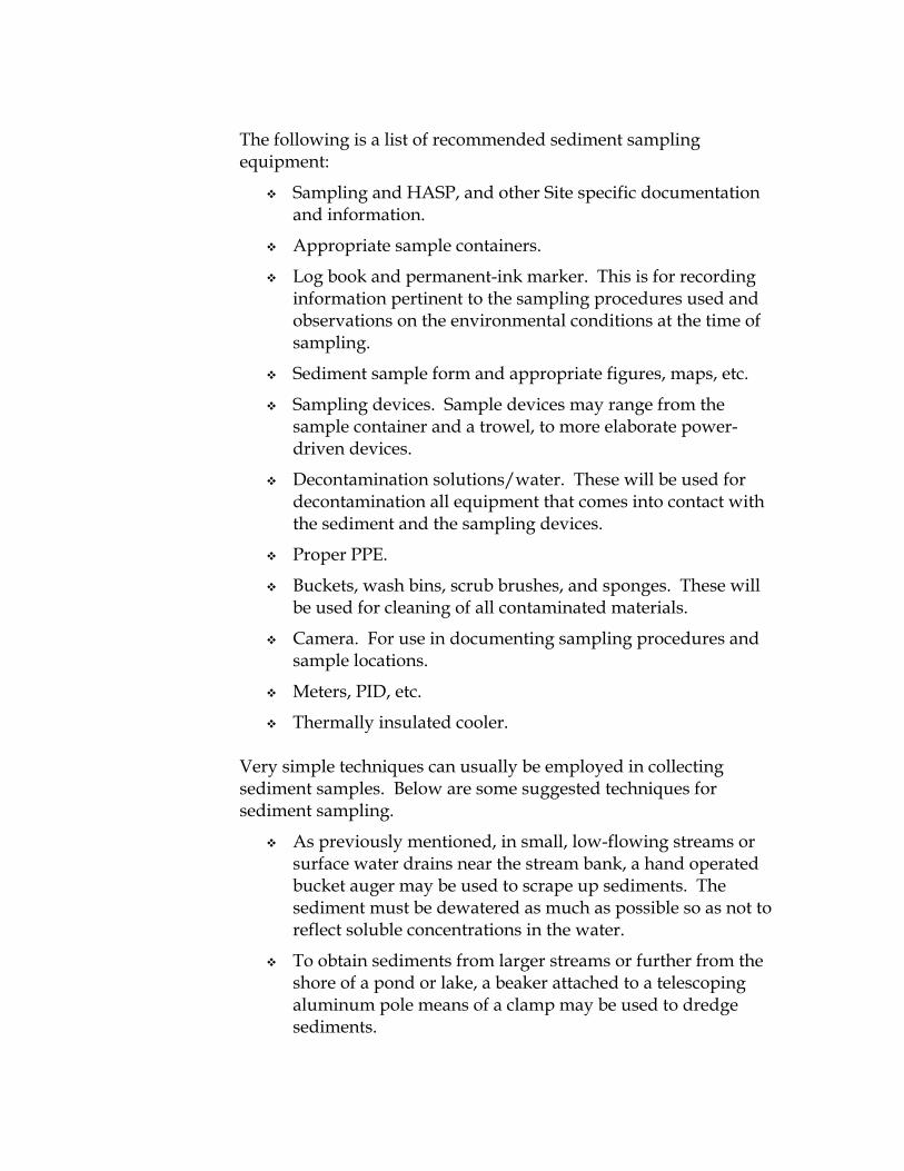
The following is a list of recommended sediment sampling equipment:
Sampling and HASP, and other Site specific documentation and information.
Appropriate sample containers.
Log book and permanent-ink marker. This is for recording information pertinent to the sampling procedures used and observations on the environmental conditions at the time of sampling.
Sediment sample form and appropriate figures, maps, etc.
Sampling devices. Sample devices may range from the sample container and a trowel, to more elaborate power-driven devices.
Decontamination solutions/water. These will be used for decontamination all equipment that comes into contact with the sediment and the sampling devices.
Proper PPE.
Buckets, wash bins, scrub brushes, and sponges. These will be used for cleaning of all contaminated materials.
Camera. For use in documenting sampling procedures and sample locations.
Meters, PID, etc.
Thermally insulated cooler.
Very simple techniques can usually be employed in collecting sediment samples. Below are some suggested techniques for sediment sampling.
As previously mentioned, in small, low-flowing streams or surface water drains near the stream bank, a hand operated bucket auger may be used to scrape up sediments. The sediment must be dewatered as much as possible so as not to reflect soluble concentrations in the water.
To obtain sediments from larger streams or further from the shore of a pond or lake, a beaker attached to a telescoping aluminum pole means of a clamp may be used to dredge sediments.

To obtain sediments from rivers or in deeper lakes and ponds, a spring-loaded sediment dredge or benthic sampler may be used. Several types of sediment core samplers exist for specialized sampling of sediments.
All of the equipment used should be decontaminated between the sampling stations using the procedures described in the following section.
19.6 SOIL SAMPLING
There are two types of soil samples; surface and subsurface. In most cases, both types will be collected as grab samples. In some cases composite sampling may be useful for obtaining data about contamination over a wide area. This provides a rough estimate of the overall extent and magnitude of contamination, while reducing the analytical costs. However, when composite sampling, it is important that extreme care be taken in documenting the location and depth of the composites. Samples for VOC analysis cannot be composited, they must be collected as grab samples.
19.6.1 Surface Soil
There are three possible scenarios for the collection of surface soil samples over a large area:
The total area may be divided by a grid system to identify specific sampling locations.
If the area is large and if complete characterization is required, a random sampling approach may be used to reduce the number of samples. In this instance the area is laid out in a grid and sample locations determined randomly.
An extremely large study area can also be divided by grids with soil samples being compostied from several locations within the grid.
The list of equipment necessary for the collection of surface soil samples may be minimal, depending upon the analytical parameters to be determined. The sampling devices may be constructed of PVC or linear polyethylene, Teflon, or stainless steel, depending upon the parameters of interest. The following is a list of equipment necessary for the collection of surface soil samples:
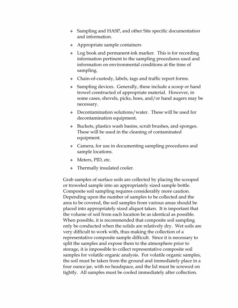
Sampling and HASP, and other Site specific documentation and information.
Appropriate sample containers
Log book and permanent-ink marker. This is for recording information pertinent to the sampling procedures used and information on environmental conditions at the time of sampling.
Chain-of-custody, labels, tags and traffic report forms.
Sampling devices. Generally, these include a scoop or hand trowel constructed of appropriate material. However, in some cases, shovels, picks, hoes, and/or hand augers may be necessary.
Decontamination solutions/water. These will be used for decontamination equipment.
Buckets, plastics wash basins, scrub brushes, and sponges. These will be used in the cleaning of contaminated equipment.
Camera, for use in documenting sampling procedures and sample locations.
Meters, PID, etc.
Thermally insulated cooler.
Grab samples of surface soils are collected by placing the scooped or troweled sample into an appropriately sized sample bottle. Composite soil sampling requires considerably more caution. Depending upon the number of samples to be collected and the area to be covered, the soil samples from various areas should be placed into appropriately sized aliquot taken. It is important that the volume of soil from each location be as identical as possible. When possible, it is recommended that composite soil sampling only be conducted when the solids are relatively dry. Wet soils are very difficult to work with, thus making the collection of a representative composite sample difficult. Since it is necessary to split the samples and expose them to the atmosphere prior to storage, it is impossible to collect representative composite soil samples for volatile organic analysis. For volatile organic samples, the soil must be taken from the ground and immediately place in a four ounce jar, with no headspace, and the lid must be screwed on tightly. All samples must be cooled immediately after collection.

19.6.2 Subsurface Soil
Subsurface soils can be collected either as grab or composite samples. The same precautions for composite sampling of surface soils apply to the compositing of subsurface soils. Although this document does not generally discuss safety factors involved in the collection of samples, it is important at this point to note that the collection of subsurface soil samples can constitute a substantial safety hazard. The most important safety factor involved is the avoidance of buried containers, pockets of highly contaminated material, and underground utilities such as electric lines, gas pipelines, water mains, etc. A thorough background information search should be completed before obtaining subsurface samples including implementing ERM’s subsurface utility policy. Utilities must be also cleared through DigSafe or an equivalent agency.
Generally, the problems encountered in the collection of subsurface soil samples are similar to those encountered in the collection of surface soil samples. Additionally, subsurface sampling must also address the depths from which the samples will be obtained. The overall approach is similar to that discussed previously for surface sampling, considering the aspects of grid systems and random versus specific sampling locations. The depths at which samples are to be taken will depend upon the suspected contaminants, their general mobility’s, and the method by which they have entered the subsurface environment. Generally, subsurface samples by hand-operated equipment and deep subsurface samples by use of a drilling rig or backhoe.
The following is a list of recommended equipment for sampling subsurface soils:
sampling health and safety plans, and other Site specific documentation and information;
appropriate sample containers;
chain-of-custody labels, tags, and traffic report forms;
log book and indelible ink marker - this is for recording observations on the environmental conditions at the time of sampling and the location;
soil sample record, boring logs, etc.;

sampling devices (depending upon the sampling methods);
decontamination solutions/water - these will be used for decontamination all equipment that comes into contact with the solids and the inside of the casing or auger flights;
buckets, wash basins, scrub brushes, and sponges - these will be used for equipment decontamination;
steam cleaner – this should be used when attempting to decontamination large pieces of equipment such as auger flights;
camera - this will be used for use in documenting sampling procedures and sample locations;
proper PPE;
meters, (PID, etc.); and
thermally insulated cooler.
Depending upon the depth and type of samples to be collected, a variety of methods are available for sampling subsurface soils. These include:
A shovel which may be used to depths of several inches or several feet, depending on soil types.
A hand auger may be used to collect subsurface samples at depths up to 4 to 5-feet; however, it mixes and thus destroys the cohesive structure and stratigraphic character of the solid preventing detailed soil description. A hand-driven soil probe (ESP) provides a means to obtain somewhat undistributed core samples. The depth will again be limited by the soil type.
Drill rig-operated sampling devices. These may be placed into two categories; hollow stem augers or Geoprobe. With hollow stem augers, either split spoon or Shelby tube can be used for sample collection. With a Geoprobe, a macro core sample can be obtained within a disposable acetate liner.
Soil samples may be collected from a backhoe trench or excavation. To collect samples from the pit, a long handled bucket auger or the backhoe bucket may be used to collect the soil from the desired depth interval. Although it should be avoided whenever possible for safety reasons, samples could also be collected by hand, with a trowel, directly from the sides of the pit.

Proper decontamination procedures should be used in cleaning all the soil sampling equipment.
19.7 Biological Sampling 19.7.1 Sample Collection
The collection of biological specimens from aquatic and terrestrial habitats may require local, state or federal licenses and/or permit. The presence of any rare, threatened, endangered species or species of special concern may also impose sampling restrictions as to types of organisms which may be harvested; the methods used to collect the samples; the area where the sampling can be conducted; and the time of the year sampling can be conducted. At the minimum, the appropriate state and/or federal agencies should be contacted to determine if any permits or licenses are required as well as to determine any restrictions which may apply.
The collection of biological samples may range from hand collection of specimens to synoptic deep sea surveys. Caution must be taken in many cases in transit to the sampling Site or in harvesting the organism in that dangerous organisms may be encountered en-route or be contained in the sample. Some types of animals (such as snapping turtles, snakes, and stingrays) can react in an unpleasant manner when threatened or trapped.
Collection in deep aquatic habitats requires appropriate personal safety equipment and adherence to the practice of safe seamanship. The use of untended equipment such as gill nets and trap nets may require the use of marking buoys to prevent boating mishaps. The use of untended equipment may require permission from the Coast Guard or marine police, especially in high traffic areas or where the deployed equipment may restrict passage. The local waterway authority should be made aware of the use of any fixed, untended sampling equipment.
A review of the Site background information may give an indication of the types of conditions which will be encountered. This will be incorporated into the sampling plan. A reconnaissance survey prior to the completion of the sampling plan generally has merit by more clearly defining Site specific restrictions, unique habitats, or habitats of special concern, accessibility, and other

features which could be considered in formulating the sampling plan.
Sampling station locations have to be determined. In terrestrial situations and in some aquatic situations, it may be necessary to lay out a visual or surveyed tract of grid. Open ocean or large lake sampling may require the use of electronic navigation equipment. For repeat sampling at the same location(s), the use of unobtrusive markers will facilitate station locations. All markers are to be removed upon completion of the final round of sampling.
After determining the objectives of the biological sampling program, Site conditions, types of organisms to be collected, specimen use, statistical considerations and access to sampling locations, a sampling plan can be prepared. In tidal aquatic systems, tidal stage may be an important component of the sampling plan. The following is a generic list of recommended biological sampling equipment. In some cases, collection in a contaminated environment will require decontamination of the equipment.
sampling health and safety plans, and other Site specific documentation and information;
appropriate sample containers;
chain-of-custody labels, tags, and traffic report forms;
waterproof labels;
log book and permanent ink marker - this is for recording information pertinent to the sampling procedures used and observation on the environmental conditions at the time of sampling;
sampling forms;
topographic sheet or map of the study area to locate stations;
sampling devices - may range from the sample container and a clean pair of forceps, to more elaborate devices;
decontamination solutions/water - these will be used for decontaminating all equipment that comes in contact with contaminated soils, sediment or water;
buckets, wash basins, scrub brushes, and sponges - these will be used for cleaning of all contaminated materials;

camera - for use in documenting sampling procedures and sample locations; and
proper PPE. The sampling techniques that are employed depend on the type of material to be collected. Following are some suggested techniques:
Terrestrial plants – For annual plants, the entire aerial portion may be harvested using shears or a knife. Larger plants may require, in addition to shears and knife, a saw or increment borer. Collection of fruits and nuts generally will be done by hand.
Terrestrial animals – For small animals several types of traps can be used including live traps and museum traps. Larger animals may require the use of a gun for capture.
Aquatic plants – Rooted aquatic plants generally are found in shallow water where they can be harvested by hand. Phytoplankton may be concentrated from water column samples by sedimentation, centrifugation or filtration.
Benthos – In shallow aquatic environments, the benthos may be sampled by using a Surber sampler, excavation and screening of a measured area of bottom, or by hand in rocky bottoms where the individual stones can be picked up slowly and the attached organisms dislodged with a stream of water. Deeper water sampling is generally done using various types of dredges such as an Ekman dredge, or with small biological trawl (SBT) which is towed by a vessel.
After a dredge sample has been secured, the sediments sample should be inspected carefully before accepted. The following acceptability criteria should be satisfied.
Sediment is not extruded from the upper surface of the sampler such that organisms may have been lost.
Overlying water is present indicating minimal leakage.
The sediment surface is relatively flat, indicating minimal disturbance on winnowing.
The entire surface of the sample is included in the sampler.
The following penetration depths are achieved:
o 4 to 5-centimeters (cm) for medium-coarse sand; o 6 to 7-cm for fine sand; and

o less than 10-cm for muddy sediment.
Nekton – Fish can be captured using a number of gear types ranging from rod and reel towed trawls. Active sampling techniques are generally less selective and more efficient, but usually require more equipment and man power. Active sampling techniques include the use of seines, trawls, electro fishing, chemical fishing and rod and reel. Passive sampling techniques are generally less labor intensive and generally more selective in the size and types of organisms captured and as such may not obtain a representative sample of the total population. Passive techniques include entanglement nets (gill and trammel nets) and entrapment devices (hoop nets, fyke nets and various types of traps). The appropriate gear type(s), and collection/development protocols will be determined by the fisheries biologist.
Zooplankton – Zooplankton are generally collects by filtering water through and appropriately sized plankton net. The net may by towed through the water or water pumped through the net. The use of a metered pump provides a more accurate estimation of the population. While towing generally provides a semi-quantitative estimate in that the volume of water passing through the net is not as well quantified. Several towing methods can be used. The speed of the craft should be adjusted and held constant so that a constant wire angle is maintained. The sample depth equals the amount of wire extended times the cosine of the wire angle. Oblique tows (more than one depth during a single tow) provide a composite of the zooplankton population in the water column. Horizontal tows sample the zooplankton in a particular water column. Horizontal tows sample the zooplankton in a particular layer of the water column. At the minimum, duplicate samples should be collected.
Net size(s) will be selected by the fisheries biologist. The following sizes are routinely used:
No. 6 (0.239-millimeters (mm)) adult copepods, ichthyoplankton;
No. 10 (0.158-mm) copepodites, microcrustanceans; and
No. 20 (0.076-mm) rotifers, nauplii. 19.7.2 Biologic Sample Preservation

Special considerations must be used in the preservation of biologic samples. Generally, ten percent buffered (sodium tetra borate) formalin is the most commonly used chemical preservative. To prepare a ten percent buffered formalin solution, add 4-ounces (oz) of borax to each gallon of one-hundred percent formalin (i.e., a fourty-percent solution of formaldehyde in water). Allow the borax to settle and use the clear supernatant (one-hundred percent formalin) to make the nine (water): one (one-hundred percent formalin) dilution. Formalin solutions should not be exposed to freezing temperature because the formalin will degrade into paraformaldehyde and will have to be discarded.
Larger specimens may require injection of perfusion (opening of the abdominal cavity to allow for quick preservative penetration of deep organs and tissues). The fisheries biologist or wildlife biologist will indicate a minimum size of specimen where special preservative methods will be required.
Certain types of samples such as phytoplankton may require alternate preservation techniques. In some cases, the specimen(s) may have to be narcotized or relaxed prior to fixation to facilitate taxonomic identification by reducing the tendency of organisms to distort their shape or automize when exposed to the preservative. The appropriate safety precautions are to be followed during the use of any preservative, relaxant or narcotic.
Any specimen/sample to be subject to chemical analysis should only come in contact with analytically clean surfaces and instruments during all stages of handling, transport, and sample preparation (such as removal of target tissue or organ). Any surface used in analytical sample preparation or storage should be pre-cleaned with pesticide grade acetone or other appropriate solvents and air dried prior to coming in contact with the sample.
19.8 DRUM SAMPLING
Drum sampling involves the sampling of a wide variety of sampling media including water, solids, oil and sludge. The method of sample collection should be adjusted as appropriate. Sampling is usually associated with waste characterization. There are two types of drum samples; grab and composite. In most cases, samples will be grab samples. In some cases, composite sampling may be useful for obtaining data about contamination for the entire

contents of the drum. However, when composite sampling, it is important that extreme care be taken in documenting the location and depth of the composites. Samples for VOC analysis cannot be composited, they must be collected as grab samples.
19.8.1 Water If the drum contains water, the procedures for sampling a surface water body should be followed; however, the use of a drum sampler is recommended.
19.8.2 Solids If the drum contains solid material, the procedures for sampling surficial soil should be followed.
19.8.3 Oil If the drum contains oil, the procedures for sampling a surface water body should be followed; however, the use of a drum sampler is recommended.
19.8.4 Sludge If the drum contains sludge, the procedures for sampling a surface water body should be followed. The following is a list of recommended equipment for sampling drums:
Sampling Health and safety plans, and other Site specific documentation and information.
Appropriate sample containers.
Chain-of-custody, labels, tags and traffic report forms.
Log book and permanent ink marker. This is for recording observations on the environmental conditions at the time of the sampling and the location.
Drum sample record.
Sampling devices (depending upon the sampling methods).

Decontamination solutions/water. These will be used for decontamination of all equipment that comes into contact with the solids and the inside of the casing or auger flights.
Buckets, wash basins, scrub brushes and sponges. These will be used for equipment decontamination.
Steam cleaner. A steam clean should be used when attempting to decontaminate large pieces of equipment such as auger flights.

Attachment E Excavation Policy and Procedures

EXCAVATION, TRENCHING, SHORING AND PERMIT-REQUIRED CONFINED SPACE ENTRY
The main concerns of trenching and excavation are ground control and
fall prevention. Before an excavation is made, a thorough effort shall be
made to determine whether underground utilities (such as sewer,
telephone, gas, fuel, water or electrical conductors) or aboveground
hazards may be encountered. Underground utility lines shall be properly
supported during excavation. Where appropriate, the respective utility
companies shall be informed of the proposed Site Work and consulted to
receive any additional advice based on their experience. Natural hazards,
such as boulders and trees, shall be removed or controlled before
excavation begins if there is a potential hazard to workers.
Very specific guidelines exist to protect employees from uncontrolled
ground movement during excavation. The guidelines are based on
ground type and excavation depth. The walls and faces of all excavations
to which employees are exposed shall be guarded by a shoring system or
sloping of the ground. All slopes shall be excavated to the degree
required in Table P-1, which is based on soil type and the ground's unique
ability to slide (see Table P-1).
TABLE P-1 Maximum Allowable Sloping Requirements* Type Maximum Allowable Slope Stable Rock Vertical (90°) Type A 3/4:1 (53°) Type B 1:1 (45°) Type C 1-1/2:1 (34°)
* Sloping for excavations greater than twenty feet in depth shall be designed by a New York State registered professional engineer.

Soil types are based on cohesiveness (exhibiting cohesion). A cohesive soil
is one which is hard to break up when dry and exhibits significant
cohesion when submerged. Soil types may be defined as:
Stable Rock - natural solid mineral matter that can be excavated with vertical sides and remain intact while exposed.
Type A soil - Soil which has an unconfined compressive strength of 1.5
tons per square foot (tsf). This includes cohesive soils such as clay, silty clay, sandy clay and clay loam. No cohesive soil is Type A if:
soil is fissured; subject to vibration; has been previously disturbed; part of a sloped, layered system which dips into the excavation on a
slope of four horizontal to one vertical; and other factors require it to be classified otherwise.
3. Type B Soil - Soil which is a cohesive soil with an unconfined
compressive strength greater than 0.5 tsf but less than 1.5 tsf. This includes all soils classified as silt, angular gravel, silt loam, sand loam and all type A soils previously disturbed. Dry rock that is not stable will be considered type B soil. Soil as well as material that is part of a layered system where the layers dip into the excavation on a slope less than four horizontal to one vertical, but only if material is classified as type B.
4. Type C Soil - Soil which has an unconfined compressive strength of 0.5 tsf or less.
Type C soil includes:
Granular soils including gravel, sand or loamy sand. Submerged soil or soil from which water is freely seeping. Submerged rock, which is not stable.

Material in a sloped, layered system where the layers dip into the excavation on a slope of four horizontal to one vertical or steeper.
Each soil and rock deposit shall be classified by a competent person as stable rock or one of the soil types described above. The Contractor shall ensure that a competent person is assigned to the Site during all excavating activities, i.e., sloping, shoring or working within excavations. A competent person is defined as one who is capable of identifying existing and predictable hazards, or working conditions which are unsanitary, hazardous or dangerous to employees and has authorization to take prompt corrective measures to eliminate them. The Contractor shall identify the competent person and submit the competent person's qualifications to the Engineer. A competent person shall perform daily inspection of excavations and adjacent areas. Inspections shall be concerned with possible cave in, failure of protective systems, hazardous atmospheres or other hazardous conditions. Where a competent person finds evidence of such hazards, Contractor employees shall be evacuated from the excavation until the unsafe condition is corrected. A vibration from nearby railroad, highway traffic or heavy equipment requires the side of the excavation to be braced to resist the additional force from such loads. A warning system shall be in place when movable equipment is operated next to an edge of an excavation and the operator does not have clear or direct view of the edge. Warning systems may be barricades, hand or mechanical signals or stop logs. No entry into an excavation in which there is accumulated water will be allowed unless adequate precautions are taken. Safety harness with attached line shall be worn at all times in excavations over four feet. Precautions include the removal of water by pumps and the diversion of any surface water by berms, dikes, ditches or plastic sheeting. If excavations are to be performed near a wall or building and may compromise its stability, a registered professional engineer shall evaluate the wall or building and ensure its stability accordingly. Stability may be achieved by designing a bracing system if necessary. If bracing is not necessary, the registered professional engineer shall indicate in writing a bracing system is not required. Excavated material shall be kept at least two feet from the edges of all excavations.

Excavations less than 20 feet in depth occurring in type C soil may be sloped at an angle no greater than 34 degrees measured from the horizontal plane. Excavations less than 20 feet in depth occurring in type B soil may be sloped 45 degrees measured from the horizontal plane. A registered professional engineer must approve sloping of excavations greater than 20 feet in depth. The Contractor may use tabulated data for slope design. The tabulated data must be in written form and shall include identification of the parameters, limits of use, and identify the New York State-registered professional engineer (PE) who approved the data. A copy of the tabulated data identifying the New York State registered PE will remain on-Site during construction activities. A sloping system designed and approved by a New York State registered PE may be utilized. The written design must illustrate the magnitude of the slope considered safe based on the project. A copy of the approved written design must remain on the job Site until final completion. Shoring systems, support systems, shield systems and other proactive systems may be used providing such systems are approved by the manufacturer, or by a New York State registered PE using the manufacturer's tabulated data. Deviations from those specifications outlined by the manufacturer or New York State registered PE shall only be made following specific written approval. If initiated, shoring systems shall be utilized for type B soils at a depth of 5 feet or greater and immediately for type C soils. Shoring systems shall be designed by a manufacturer, New York State-registered PE or be consistent with Attachment 1 of this Appendix (OSHA Minimum Timber Shoring Requirements). All shoring systems used at a depth of 20 feet or greater require approval from a New York State-registered PE. In excavations greater than 4 feet in depth, ladders must be located every 25 feet and extend three feet over the surface. Any excavation activities below the ground water table shall be examined and approved in writing by a New York State registered PE.

Attachment F Map and Directions for Hospital


Attachment G
Daily Safety Meeting Form

Daily Safety Meeting Documentation Form
Project Name: Former No. 2 Mill Facility Soil Excavation Project Number:0128439 0128439 Meeting Date & Time:
ERM Remediation & Construction Management 1 Form Rev.: 05-08
Document Routing SSO Retain copy in site health & safety file.
1. Who lead the meeting today? 2. What work will be conducted on site today by whom? Work Task Conducted By 3. What overlapping operations will occur today? 4. Any follow-up from previous Major Incidents, Near Misses, Unsafe Acts or Unsafe
Conditions discussed today? 5. What additional safety topics were covered? 6. Are there any new / short-service personnel on site today?

Daily Safety Meeting Documentation Form
Project Name: Former No. 2 Mill Facility Soil Excavation Project Number:0128439 0128439 Meeting Date & Time:
ERM Remediation & Construction Management 2 Form Rev.: 05-08
7. Who attended the safety meeting today? Name Company Signature
Meeting documented by…
Name: Signature:

Attachment H Unsafe Act, and Unsafe Condition Report Form

Unsafe Act / Unsafe Condtion Report Form
Report Type (Check One): Unsafe Act Unsafe Condition Project Name: Project Number: Report Number:
ERM Remediation & Construction Management 1 Form Rev.: 05-08
Document Routing SSO To PM and RCM Coordinator 24 hours after observance / follow-up. Retain
copy in site health & safety file. PM After completion to office health & safety file
Name of person who observed event: Observer’s employer:
1. When did the observation occur? Date:
Time of Day:
2. What was observed? 3. Which event categories apply? Traffic-related
Travel-related Falls from height Slips or trips
Bodily Reaction and Exertion
Equipment-operation related
Aggressive and Violent Acts
Fires or Explosions
Impact or contact with objects or equipment
Exposure to the release of chemicals, substances or environments
Vandalism, theft or site control breach
Electrocution
Other (specify):
4. Event Principal(s) ERM or RCM Subcontractor Third Party 5. What were the corrective actions taken, by whom, and when were they completed?
Corrective Action Assigned to… Completion Date

Unsafe Act / Unsafe Condtion Report Form
Report Type (Check One): Unsafe Act Unsafe Condition Project Name: Project Number: Report Number:
ERM Remediation & Construction Management 2 Form Rev.: 05-08
Report Completed by…
Name:
Signature: Project Role:
Date:

Attachment I Near Reporting and Investigation Form

Near Miss Observation Report Form
Project Name: Project Number: Report Number:
ERM Remediation & Construction Management 1 Form Rev.: 05-08
Document Routing SSO To PM and RCM Coordinator 24 hours after observance / follow-up. Retain
copy in site health & safety file. PM After completion to office health & safety file
Name of person preparing Part I:
Name of person who observed event:
Date Part I was prepared:
PART I: ABOUT THE NEAR MISS 1. When did the observation occur? Date:
Time of Day:
2. What were the weather conditions at the time?
Light Conditions at Incident Location
If Outdoor: Sunny Cloudy Night / Artificial Light Dawn / Dusk
If Indoor: Low Light Normal Light
None Drizzle Rain Precipitation
Sleet Snow Temperature (F)
Relative Humidity (%)
Wind Speed (mph)
3. What was observed?

Near Miss Observation Report Form
Project Name: Project Number: Report Number:
ERM Remediation & Construction Management 2 Form Rev.: 05-08
4. Which event categories apply? Traffic-related
Travel-related Falls from height Slips or trips
Bodily Reaction and Exertion
Equipment-operation related
Aggressive and Violent Acts
Fires or Explosions
Impact or contact with objects or equipment
Exposure to the release of chemicals, substances or environments
Vandalism, theft or site control breach
Electrocution
Other (specify):
5. Where was the observation made? PART II: FOLLOW-UP 6. Actions leading to Observation. Check all that apply and explain. Failure to observe warning Failure to use PPE Failure to warn Delayed discovery Procedure not followed Abuse / misuse of equip. Lack of site awareness Other: Explanation: 7. Conditions leading to Observation. Check all that apply and explain. Temperature / weather Inadequate maintenance Nature (animals, plants) Time pressure / constraints Improper design / engin. Construction deficiencies Other: Explanation:

Near Miss Observation Report Form
Project Name: Project Number: Report Number:
ERM Remediation & Construction Management 3 Form Rev.: 05-08
8. Job factors leading to Observation. Check all that apply and explain. Leadership / supervision Lack of / inadequate PPE Inadequate inspections Inadequate communication Inadequate training Inadequate work procedures / practices
Improper / defective tools / equip.
Other: Explanation: 9. Personnel factors leading to Observation. Check all that apply and explain. Physical capability Physical stress / fatigue Mental stress Knowledge of task Employee skills Attention to details Other: Explanation: 10. Event Principal(s) ERM or RCM Subcontractor Third Party 11. What were the corrective actions taken, by whom, and when were they completed?
Corrective Action Assigned to… Completion Date Follow-up Completed by…
Name: Signature:
Project Role: Date:

Attachment J Incident Reporting and Investigation Form

Incident Report & Investigation Form FOR ERM INTERNAL USE ONLY CONFIDENTIAL - WITHOUT PREJUDICE REPORT
Project Name:GreenPac Former #2 Mill facility Project Number:0128439 Report Number:
ERM 1 Form Rev. 05-08
Document Routing SSO After completion to site health & safety file Project Manager After completion to office health & safety file
PART I: INCIDENT DATA AND SUMMARY Instructions: SSO to complete Part I of this form within 24 hours after the occurrence
of the Incident or per OpCo instruction in the case of very severe Incidents. SSO to verbally notify Project Manager and ERM Coordinator as soon as practicable following occurrence of the Incident. Project Manager and ERM Coordinator to continue verbal communication per ERM Health & Safety Management System guidance or per applicable client requirements. If a piece of information does not apply, put N/A in the block.
1. Where did the Incident occur? Site Name:
Site Address:
Location Within the Site:
2. When did the Incident occur? Date:
Time of Day:
3. What were the weather conditions at the time?
Light Conditions at Incident Location
If Outdoor: Sunny Cloudy Night / Artificial Light Dawn / Dusk
If Indoor: Low Light Normal Light
None Drizzle Rain Precipitation
Sleet Snow Temperature (F)
Relative Humidity (%)
Wind Speed (mph)
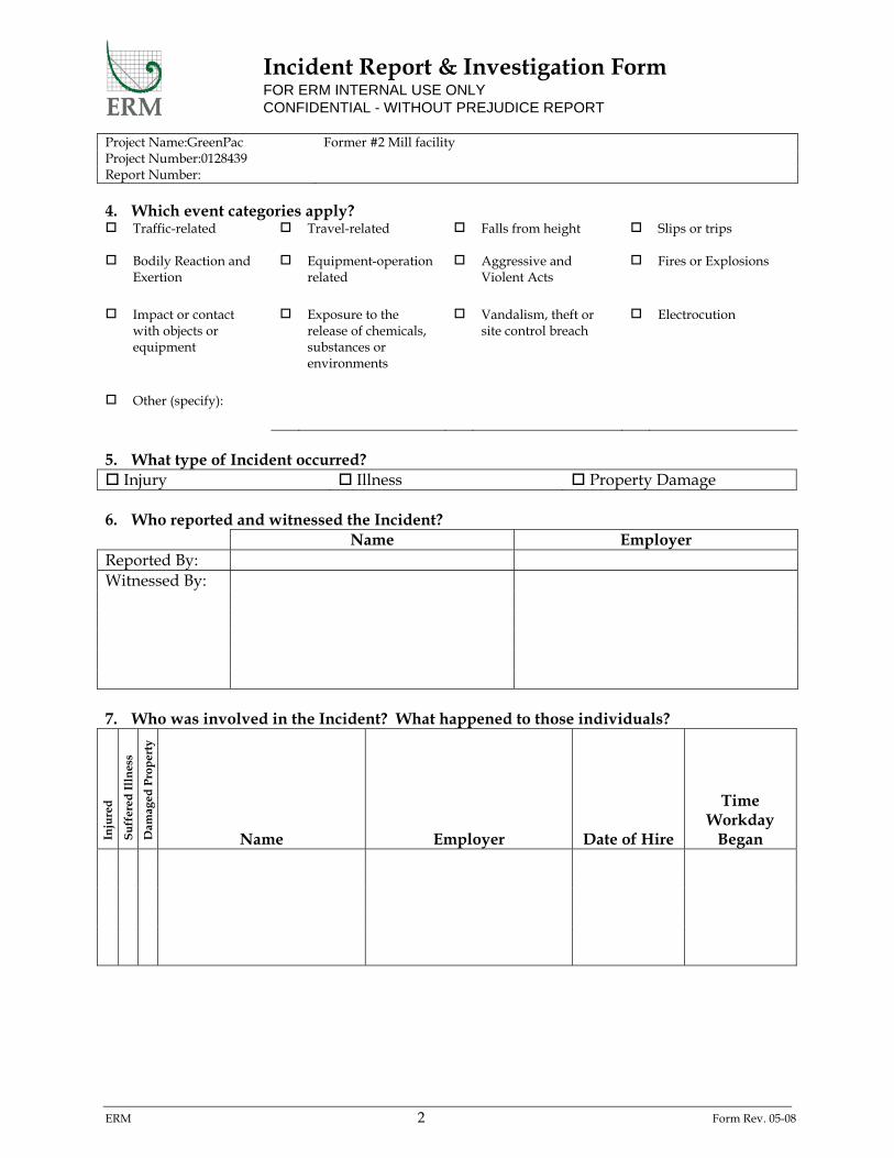
Incident Report & Investigation Form FOR ERM INTERNAL USE ONLY CONFIDENTIAL - WITHOUT PREJUDICE REPORT
Project Name:GreenPac Former #2 Mill facility Project Number:0128439 Report Number:
ERM 2 Form Rev. 05-08
4. Which event categories apply? Traffic-related
Travel-related Falls from height Slips or trips
Bodily Reaction and Exertion
Equipment-operation related
Aggressive and Violent Acts
Fires or Explosions
Impact or contact with objects or equipment
Exposure to the release of chemicals, substances or environments
Vandalism, theft or site control breach
Electrocution
Other (specify):
5. What type of Incident occurred? Injury Illness Property Damage 6. Who reported and witnessed the Incident? Name Employer Reported By: Witnessed By: 7. Who was involved in the Incident? What happened to those individuals?
Inju
red
Su
ffer
ed I
lln
ess
Dam
aged
Pro
per
ty
Name Employer Date of Hire
Time Workday
Began

Incident Report & Investigation Form FOR ERM INTERNAL USE ONLY CONFIDENTIAL - WITHOUT PREJUDICE REPORT
Project Name:GreenPac Former #2 Mill facility Project Number:0128439 Report Number:
ERM 3 Form Rev. 05-08
8. What activity/task was taking place just prior to the Incident? (Describe the activity/task
as well as tools, equipment and material involved that set the stage for the incident. What was the worker doing?)
9. What changed about the situation or task to cause the Incident? How did the incident
happen? 10. What was the outcome of the Incident? (e.g., “Injury: 2 cm long cut to left ring finger”,
“Property Damage: Snapped overhead telephone cable”) 11. What object or substance directly harmed the employee? (e.g., Concrete floor, chlorine,
H2S, manhole cover. If this question does not apply to the incident, write N/A.) 12. What immediate actions were taken by whom in response to the Incident?
Action Taken By… Employer

Incident Report & Investigation Form FOR ERM INTERNAL USE ONLY CONFIDENTIAL - WITHOUT PREJUDICE REPORT
Project Name:GreenPac Former #2 Mill facility Project Number:0128439 Report Number:
ERM 4 Form Rev. 05-08
13. If medical treatment was given away from worksite, state name and mailing address of
both the facility and treating health care professional. Facility Professional Name: Address:
14. If outside medical treatment was received, provide the following details:
Name Employer Rec
eive
d p
resc
rip
tion
for
m
edic
atio
n?
Tre
ated
in a
n e
mer
gen
cy
room
?
Was
em
plo
yee
hos
pit
aliz
ed o
vern
igh
t as
an in
-pat
ien
t?
15. If there were fatalities resulting from this Incident, provide names and the date of death.

Incident Report & Investigation Form FOR ERM INTERNAL USE ONLY CONFIDENTIAL - WITHOUT PREJUDICE REPORT
Project Name:GreenPac Former #2 Mill facility Project Number:0128439 Report Number:
ERM 5 Form Rev. 05-08
16. Attach the report of any external investigations conducted into this Incident. Also attach
any photographs or sketches that help to describe the Incident. Describe attachments below.
Part I Completed by…
Name: Signature:
Project Role: Date:

Incident Report & Investigation Form FOR ERM INTERNAL USE ONLY CONFIDENTIAL - WITHOUT PREJUDICE REPORT
Project Name:GreenPac Former #2 Mill facility Project Number:0128439 Report Number:
ERM 6 Form Rev. 05-08
PART II: CAUSES AND PLANS TO PREVENT RECURRENCE Instructions: ERM Health & Safety Coordinator to lead effort to complete Part
II of this form with cooperation of Site Safety Officer, Project Manager, and appropriate site personnel
17. Actions leading to Incident. Check all that apply and explain. Failure to observe warning Failure to use PPE Failure to warn Delayed discovery Procedure not followed Abuse / misuse of equip. Lack of site awareness Other: Explanation: 18. Conditions leading to Incident. Check all that apply and explain. Temperature / weather Inadequate maintenance Nature (animals, plants) Time pressure / constraints Improper design / engin. Construction deficiencies Other: Explanation: 19. Job factors leading to Incident. Check all that apply and explain. Leadership / supervision Lack of / inadequate PPE Inadequate inspections Inadequate communication Inadequate training Inadequate work procedures / practices
Improper / defective tools / equip.
Other: Explanation:

Incident Report & Investigation Form FOR ERM INTERNAL USE ONLY CONFIDENTIAL - WITHOUT PREJUDICE REPORT
Project Name:GreenPac Former #2 Mill facility Project Number:0128439 Report Number:
ERM 7 Form Rev. 05-08
20. Personnel factors leading to Incident. Check all that apply and explain. Physical capability Physical stress / fatigue Mental stress Knowledge of task Employee skills Attention to details Other: Explanation: 21. Event Principal(s) ERM or ERM Subcontractor Third Party 22. What were the corrective actions taken, by whom, and when were they completed?
Corrective Action Assigned to… Completion Date 23. Was this Incident recordable/reportable under any governmental requirement? Yes
Determined By:
No
Project Role:
Part II Completed by…
Name:
Signature:
Project Role:
Date:

Attachment K NYSDEC Community Air Monitoring Program

COMMUNITY AIR MONITORING PLAN FORMER No.2 MILL FACILITY SITE – NIAGARA FALLS, NEW YORK A Community Air Monitoring Plan (CAMP) involves real-time monitoring for volatile organic compounds (VOCs) and particulate matter (i.e., dust) at the downwind perimeter of each designated work area when intrusive activities are in progress. Intrusive activities include soil or waste excavation, staging, or handling; test pitting or trenching; and/or the installation of soil borings or ground water wells. The CAMP provides a measure of protection for on-Site workers and the downwind community (i.e., off-Site receptors including residences, parks, businesses, etc.) not directly involved with the subject work activities. Routine monitoring is required to evaluate concentrations and corrective action and/or work stoppage may be required to abate emissions detected at concentrations above specified action levels. Routine data collected during implementation of the CAMP may also help document that work activities did not spread compounds of potential concern off-Site through the air. Reliance on the procedures and action levels described in this CAMP should not preclude simple, common sense measures to keep VOCs, dust, and odors at a minimum around work areas. COMMUNITY AIR MONITORING PLAN Compounds of potential concern include several VOCs and particulate matter (i.e., dust). VOC concentrations in air will be measured using a calibrated photoionization detector (PID). Particulate matter concentrations will be measured using a calibrated electronic aerosol monitor. Relevant weather conditions including wind direction, speed, humidity, temperature, and precipitation will be measured and recorded prior to the initiation of subsurface intrusive activities. Background readings of VOCs and particulate matter will be collected at a minimum of five locations on Site prior to the initiation of field work on each day that subsurface intrusive work will be performed. Additional background measurements may be collected if weather conditions change significantly. Continuous monitoring for VOCs and particulate matter will be performed downwind of the work area during subsurface intrusive activities. Periodic monitoring for VOCs will be performed during non-intrusive activities if requested by an NYSDEC and/or NYSDOH on-Site representative. Non-intrusive activities include any work activity that does not disturb the subsurface or staged soil piles, including routine Site visits, collection of ground water samples from Site wells, installation of remedial equipment, operations and maintenance, surveying, etc. Periodic monitoring will consist of collecting one reading downwind of the work area at the following intervals:

upon arrival at a sample location or other work activity location; during performance of the relevant work activity; during the opening of a well cap (if applicable); during well baling or purging procedures (if applicable); and prior to leaving a sample location or other work activity location. VOC RESPONSE LEVELS AND CORRECTIVE ACTIONS VOCs will be monitored at the downwind perimeter of the immediate work area on a continuous basis during intrusive activities. Upwind concentrations will be measured at the start of each workday, during the work activity, and at the end of each work day to establish background conditions. Monitoring equipment that does not require factory calibration will be calibrated at least once a day. Calibration may be performed more frequently if Site conditions or instrument operating conditions are highly variable. The monitoring equipment should be capable of calculating 15-minute running average concentrations, which will be compared to the levels specified below. If the ambient air concentration of total VOCs at the downwind perimeter of the
work area exceeds 5-parts per million (ppm) above background for the 15-minute average, work activities will be temporarily halted and monitoring continued. If the total VOC concentration readily decreases (per instantaneous readings) below 5-ppm over background, work activities can resume with continued monitoring.
If total VOC concentrations at the downwind perimeter of the work area persists at
concentrations greater than 5-ppm over background but less than 25-ppm, work activities will be halted, the source of the VOCs identified, corrective action will be taken to abate emissions (if the source is related to Site remedial activities), and monitoring will be continued. After these steps, work activities will resume provided that the total VOC concentration 200-feet downwind of the work area, or half the distance to the nearest potential receptor, whichever is less (but in no case less than 20-feet), is below 5-ppm above background for the 15-minute average.
If the total VOC concentration is greater than 25-ppm above background at the
perimeter of the work area, intrusive work activities will be halted and the source of the VOCs will be identified. Work will resume when additional continuous monitoring demonstrates that VOC concentrations have dropped below 25-ppm for a minimum of one-half hour, and the total VOC concentration 200-feet downwind of the work area, or half the distance to the nearest potential receptor, whichever is less (but in no case less than 20-feet), is below five ppm above background for the 15-minute average.

All 15-minute readings will be recorded and will be available for review by NYSDEC and/or NYSDOH personnel. Instantaneous VOC readings (if any) used for decision purposes will also be recorded. PARTICULATE MATTER RESPONSE LEVELS AND CORRECTIVE ACTIONS Fugitive dust migration from the work area will be visually assessed during intrusive activities. Particulate concentrations will be monitored continuously at the downwind perimeter of the work area during intrusive activities. Particulate monitoring will be performed using real-time electronic aerosol monitoring equipment capable of measuring particulate matter less than 10-micrometers in size (PM-10) and capable of integrating over a period of 15 minutes for comparison to the airborne particulate action levels referenced below. The monitoring equipment will be equipped with an audible alarm to indicate an exceedance of a specified action level. If the downwind PM-10 concentration is 100-micrograms per cubic meter (g/m3) greater than background for the 15-minute period, or if airborne dust is observed leaving the work area, dust suppression techniques will be employed. Work may continue with dust suppression techniques provided that downwind PM-10 concentration does not exceed 150-g/m3 above background and provided that significant visible dust is not migrating from the work area. If downwind PM-10 concentrations are greater than 150-g/m3 above background, intrusive activities will be stopped and a re-evaluation of the intrusive activities will be initiated. Work can resume provided that dust suppression measures and/or other engineering controls are successful in reducing the downwind PM-10 concentration to within 150-mcg/m3 of background and in preventing significant visible dust migration. All 15-minute readings will be recorded and will be available for review by NYSDEC and/or NYSDOH personnel. Instantaneous readings (if any) used for decision purposes will also be recorded.